US8322510B2 - System for automatically identifying, conveying and addressing biological material specimens - Google Patents
System for automatically identifying, conveying and addressing biological material specimensDownload PDFInfo
- Publication number
- US8322510B2 US8322510B2US12/745,525US74552508AUS8322510B2US 8322510 B2US8322510 B2US 8322510B2US 74552508 AUS74552508 AUS 74552508AUS 8322510 B2US8322510 B2US 8322510B2
- Authority
- US
- United States
- Prior art keywords
- conveying
- test tube
- lane
- main lane
- lanes
- Prior art date
- Legal status (The legal status is an assumption and is not a legal conclusion. Google has not performed a legal analysis and makes no representation as to the accuracy of the status listed.)
- Active, expires
Links
Images


Classifications
- G—PHYSICS
- G01—MEASURING; TESTING
- G01N—INVESTIGATING OR ANALYSING MATERIALS BY DETERMINING THEIR CHEMICAL OR PHYSICAL PROPERTIES
- G01N35/00—Automatic analysis not limited to methods or materials provided for in any single one of groups G01N1/00 - G01N33/00; Handling materials therefor
- G01N35/00584—Control arrangements for automatic analysers
- G01N35/00722—Communications; Identification
- G01N35/00732—Identification of carriers, materials or components in automatic analysers
- G—PHYSICS
- G01—MEASURING; TESTING
- G01N—INVESTIGATING OR ANALYSING MATERIALS BY DETERMINING THEIR CHEMICAL OR PHYSICAL PROPERTIES
- G01N35/00—Automatic analysis not limited to methods or materials provided for in any single one of groups G01N1/00 - G01N33/00; Handling materials therefor
- G01N35/02—Automatic analysis not limited to methods or materials provided for in any single one of groups G01N1/00 - G01N33/00; Handling materials therefor using a plurality of sample containers moved by a conveyor system past one or more treatment or analysis stations
- G01N35/04—Details of the conveyor system
- G—PHYSICS
- G01—MEASURING; TESTING
- G01N—INVESTIGATING OR ANALYSING MATERIALS BY DETERMINING THEIR CHEMICAL OR PHYSICAL PROPERTIES
- G01N35/00—Automatic analysis not limited to methods or materials provided for in any single one of groups G01N1/00 - G01N33/00; Handling materials therefor
- G01N35/00584—Control arrangements for automatic analysers
- G01N35/00722—Communications; Identification
- G01N35/00732—Identification of carriers, materials or components in automatic analysers
- G01N2035/00792—Type of components bearing the codes, other than sample carriers
- G01N2035/00801—Holders for sample carriers, e.g. trays, caroussel, racks
- G—PHYSICS
- G01—MEASURING; TESTING
- G01N—INVESTIGATING OR ANALYSING MATERIALS BY DETERMINING THEIR CHEMICAL OR PHYSICAL PROPERTIES
- G01N35/00—Automatic analysis not limited to methods or materials provided for in any single one of groups G01N1/00 - G01N33/00; Handling materials therefor
- G01N35/02—Automatic analysis not limited to methods or materials provided for in any single one of groups G01N1/00 - G01N33/00; Handling materials therefor using a plurality of sample containers moved by a conveyor system past one or more treatment or analysis stations
- G01N35/04—Details of the conveyor system
- G01N2035/046—General conveyor features
- G01N2035/0467—Switching points ("aiguillages")
Definitions
- the present inventionrelates to a system for automatically identifying, conveying and addressing biological material specimens.
- the biological material specimensAfter having been collected in specific containers, such as, in the case of blood, plastic or glass test tubes, the biological material specimens reach the test laboratory and are subjected to a series of steps aimed at their preparation, testing and subsequent preservation.
- the first action to be performed on a biological material specimenis to identify it, i.e. to gather all the information needed for correct specimen testing and reporting.
- Such an informationmay be, for example, identification data of the person who supplied the biological material (this ensures the univocal identification thereof, an essential requirement for correct result reporting at the end of the tests), biological material type (blood, urine, saliva, etc.), type of test to be performed on the specimen (this information is needed to define the type of treatment to be performed on the biological material specimen during the step of pre-testing).
- Step of pre-testingThe step of biological material specimen pre-testing includes all the actions which must be performed on the specimen in order to prepare it for the step of testing. If the biological material to be treated is blood, these actions consists in centrifuging the sample contained in test tubes and subsequently removing the cap from the same, in order to facilitate the extraction of the biological material from the test tubes during the step of testing.
- a step of test tube aliquotingis included, in which “daughter” test tubes are created from the main test tube, named “mother” test tube, in which the biological material contained in the mother test tube is distributed.
- the step of testingincludes the extraction of the biological material specimen from the corresponding container and the actual chemical testing of the specimen.
- the amount of extracted specimen and the number of tests which are performeddepend on the number of tests which must be carried out on the biological specimen.
- Step of post-testingThe step of post-testing consists of two main activities: reporting the test results performed during the step of testing on the biological material specimen and preserving the same.
- the residual biological material specimen contained in the corresponding containeris preserved in refrigerated environments in order to ensure integrity in case of further tests.
- the containeris closed by applying either the original cap or possibly other type of sealing.
- a systemis therefore needed in order to automate the entire working cycle performed on a biological material specimen to be tested, from the first step of identifying the specimen to the collection of the results.
- EP-1106542A1discloses an automated laboratory system comprising a rotational diverting device.
- the objectis reached by an automated laboratory system as disclosed in claim 1 .
- a barcodeis a string of characters suitable to be read by a barcode reader.
- the control unitmay be an application software installed on a personal computer, provided with a memory containing all the informations needed for performing the correct activities on the test tubes and adapted to store their lifecycle during the process.
- the test tube informationsincludes, for example, personal data of the person from whom the biological material was taken, the tests to be performed on such a biological material, and, in some cases, the level of urgency required for processing the test tube.
- the application software installed on the control unithas the capacity of managing urgencies by assigning given priorities to the conveying devices containing the test tubes deemed urgent during the process on the conveying system. Such priorities are made possible also by using appropriate priority and overtaking lanes present in the conveying system.
- the devices mounted on the systemare connected to the control unit so as to communicate therewith and receive commands in real time.
- the stations or modules dedicated to the steps of pre-testing, testing and post-testingphysically interface in given positions of the system. Such positions are reachable by the test tubes contained in the conveying devices or carriers and represent the points in which the test tube is processed by the modules.
- the modules connected to the systemmay communicate with the system control unit by means of different communication protocols (serial, TCP/IP. etc.).
- Such a communicationconsists in sending information concerning the state of the modules (from the modules to the control unit), and in sending possible executive commands (from the control unit to the modules).
- the conveying device or carrierconsists in a container, adapted to contain the test tube in vertical, stable position. It moves along the system and may reach all the interfacing positions with the modules.
- the systememploys stop and diverting devices, adapted to stop and divert the conveying devices close to diversions and priority lanes.
- the test tube conveying deviceis identified and checked by transmission of an identification code by a chip contained in the conveying device to a network of antennas arranged along the conveying system.
- test tubeis detected by a test tube detecting system which, in addition to detecting its actual presence, also identifies some physical features useful during the subsequent steps of the process. Consequently to confirming the presence of the test tube in the conveying device, the control unit activates the barcode reader which identifies and sends the univocal identification code of the test tube to the control unit.
- the association of the test tube and the corresponding conveying deviceis performed by the control unit after identifying the test tube. This allows to track and check the position of the test tube during all the steps of the process on the system by knowing the identification code of the conveying device which contains it.
- FIG. 1is a top plan view of the system according to the present invention.
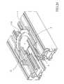
- FIG. 2is a perspective view of a portion of the system
- FIG. 3is a section view taken along the line in FIG. 1 ;
- FIG. 4is a top plan view of the carrier detecting device
- FIG. 5is a perspective view of a portion of the system with the detecting and identifying point of the test tube in the carrier on a conveyor belt;
- FIG. 6is a top plan view of the portion in FIG. 5 ;
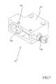
- FIG. 7is a perspective view of a stop gate used to stop the carriers moving on the conveyor belt
- FIG. 8is a front view of the stop gate
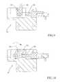
- FIG. 9is a section view taken along line IX-IX in FIG. 8 ;
- FIG. 10is a section view similar to that in FIG. 9 with the gate in resting position;
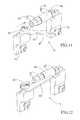
- FIG. 11is a perspective view of a diverting device used to divert the carriers moving on the conveyor belt;
- FIG. 12is a view similar to that of FIG. 11 with the diverter in resting position;
- FIG. 13is a perspective top view of a portion of the system comprising an overtaking lane
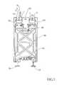
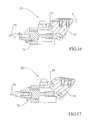
- FIG. 14is a front view of a portion of the system comprising a belt lifting device
- FIG. 15is a perspective view of the belt lifting device
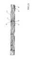
- FIG. 16shows a longitudinal section view of the lifting device in FIG. 15 in resting position
- FIG. 17is a section view similar to that in FIG. 16 with the lifting device in working position;
- FIG. 18is a perspective view of a portion of the system with a test tube U-turn device
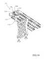
- FIG. 19is a perspective bottom view of the device in FIG. 18 ;
- FIG. 20is a perspective view of an angled portion of the system
- FIG. 21is a top plan view of a portion of the system with an empty carrier lane for urgent test tubes
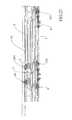
- FIG. 22is a top plan view of a portion of the system with urgent test tubes close to the testers;
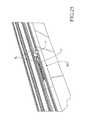
- FIG. 23shows a top plan view of a T-shaped portion of the system
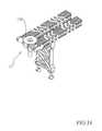
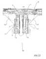
- FIG. 24is a perspective view of a portion of the system comprising a module adapted to adjust the flow of carriers;
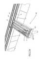
- FIG. 25is a perspective view of a portion of the system including a lane for manually loading urgent test tubes into carriers;
- FIG. 26is a perspective view of a portion of the system comprising a further test tube U-turn device
- FIG. 27shows a perspective view of a system portion comprising a device for blocking the test tube in a sampling position, in resting position;
- FIG. 28shows a perspective view of a system portion comprising a device for blocking the test tube in a sampling position, in blocking position.
- FIG. 1shows a system according to the present invention comprising main conveying lanes 1 having the function of:
- the reciprocally parallel main 1 and secondary 2 lanesaccommodate motorized conveyor belts 62 having the purpose of conveying the carriers 3 ( FIGS. 2 and 3 ).
- a couple of belts 62which run in one direction, and a couple of belts 62 , which run in the opposite direction ( FIGS. 2 and 3 ) are provided for each straight segment of the system (angular and T-shaped connections, as described below).
- the conveying systemconsists of modules 51 ( FIG. 2 ) which are mutually assembled in a variable number according to different configurations for complying with the various needs of test laboratories using the present invention.
- Each module 51in addition to the two couples of lanes 1 - 2 , comprises a sliding structure 63 of the belt 62 , on which an upper guard 64 is mounted ( FIG. 3 ) and which rests on a lower profile 65 by means of an upright 66 .
- the lower profile 65rests on feet 29 which are adjustable in height.
- a cable holder structure 68( FIG. 3 ) is fixed under the two pairs of lanes 1 - 2 .
- the belt 62consists of reticular polyurethane coated with impregnated fabric which ensures a low friction coefficient with the resting surface of the carrier 3 during the movement.
- the conveying belt 62 endsare fused by means of an appropriate fusing tool during the installation of the system after the assembly of the conveying modules 51 .
- This type of fusingensures a homogenous seam between the two ends of the belt forming the conveyor and prevents oscillations of the test tube 4 contained in the carrier 3 when the carrier encounters the belt seam as it travels in the system.
- Some pre-testing 19 - 20 and post-testing 21 modulesexert a downward, vertical pressure on the test tube 4 during a step of the process.
- the decapper module 20responsible for removing the cap from the test tube during the step of pre-testing.
- a vertical downward compressing actionon the test tube 4 contained in the carrier 3 .
- Such a compressionis transmitted by the carrier 3 to the belt 62 underneath.
- the transmitted pressureSince the carrier 3 is stationary during the step of decapping of the test tube 4 , in the operating point of the decapper module 20 , the transmitted pressure generates a pinching of the belt 62 between the carrier 3 and the lower part of the structure 63 (which is the sliding surface of the belt). Such a pinching causes the belt 62 to slow down and causes wearing of the supporting base of the carrier 3 on the belt 62 by effect of the rubbing generated by the movement of the belt 62 .
- the systemis provided with a belt lifting device 10 ( FIG. 14-17 ) in order to overcome such a problem.
- Said belt lifting device 10has the function of lifting the belt 62 by approximately 1.5 mm close to the action points of the modules which have the described problem, in order to generate a suspension of the belt 62 in said points. Such a suspension prevents the contact of the belt 62 against the structure 63 ( FIG. 14 ).
- Said lifting device 10consists of an external body 71 containing a pneumatic cylinder 72 fed by means of a flow governor 73 .
- the movement of such a cylindergenerates the rotation of a runner 74 about a pin 75 .
- the runner 74In absence of carrier 3 (resting conditions), the runner 74 is in the lowered position ( FIG. 17 ) and the belt is not raised.
- the pneumatic cylinder 72moves in the direction of the runner, generating a clockwise rotation. Following such a rotation, the runner 74 is arranged in the position shown in FIG. 16 generating the lifting of the belt 62 .
- the presence of a spring (not shown) inside the beltallows the return to horizontal position.
- a U-turn device 11( FIGS. 18-19 ), having the function of transferring the carrier 3 from the couple of belts 62 running in one direction to the couple of belts 62 running in the opposite direction, is found at the end of the conveying system in order to allow the carrier 3 to reverse the direction of motion.
- Said U-turn device 11comprises a thin plastic plate 110 mounted on a vertical shaft 112 turned by a motor 113 .
- Said motor 113is present on each end of the conveying system and in addition to generating the rotation of the plate 110 also has the function of moving one of the two couple of belts 62 .
- Motionis transmitted by means of a belt 114 and an angle transmission 116 to a pulley 115 which, by turning, generates the motion of the couple of belts 62 ( FIG. 19 ).
- Said U-turn device 11may be present also in an intermediate segment of the conveying system ( FIG. 26 ), in order, when needed, to allow U-turns of empty carriers 3 or carriers containing test tubes which must not be processed by the modules connected to the conveying system subsequent to the point in which the U-turn is present.
- the presence of U-turnsis particularly useful in large-sized conveying systems.
- a carrier 3 the direction of which must be invertedproceeds on the main lane 1 and is channeled into the U-turn device 11 ; if instead the carrier needs to proceed in rectilinear direction along the conveying system it is conveyed onto the secondary lane 2 to overcome the U-turn.
- the conveying systemis a modular structure consisting of a varying number of conveying modules 51 . These features allows to adapt the conveying system to the various test laboratories in which it is installed, thus complying with the logistic features of such laboratories. This objective is reached also in virtue of the use of the following two modules:
- the corner module 12is used to obtain an angular path of the conveying system.
- Said angled modulemay be made according to different angles, e.g. the embodiment herein described is a 90° angle module which confers an L-shape to the conveying system.
- FIG. 20is a perspective view of such a module 12 , consisting of the perpendicular intersection of two conveying modules 51 .
- Two direction changing devices 111entirely similar to the U-turn devices 11 described above, allow the carrier 3 to travel from one conveying module 51 to the other arranged in a perpendicular position.
- the plate 110 in internal positionguarantees the passage of the carrier 3 from the main conveying unit 1 to the one in perpendicular direction, while the external plate 110 guarantees the passage of the carrier from the secondary conveying unit 2 to the one in perpendicular direction.
- the T-shaped turning module( FIG. 23 ) comprises two rectilinear segments 16 - 17 having a “T”-shaped configuration.
- the segment 16is joined by the ends to further rectilinear segments of the type shown in FIG. 4 and comprises a main lane 1 , in which runs the carrier 3 , which is diverted onto the secondary lane 2 of the segment 16 , being routed onto the secondary lane 2 of the segment 17 by means of a plate 110 .
- the shape of an upper guard 79forces the travelling carrier 3 to pass into the main lane 1 of the segment 17 ( FIG. 25 ).
- the return of the carrier 3 onto the segment 16 of the T-shaped module 15is equivalent: the carrier 3 is forced by the shape of the upper guard 79 to travel onto the secondary lane 2 of the segment 17 , to then be diverted onto the secondary lane 2 of the segment 16 by means of a further plate 110 .
- a carrier detecting apparatusIn order to track the path and check the right addressing of the conveying system, the position of the moving carrier 3 is recorded by a carrier detecting apparatus.
- a carrier detecting apparatusis capable of identifying the presence and the identity of the carrier 3 in real time as the carrier 3 travels in the conveying system. It is based on radio-frequency identification technology (RFID), and consisting of a network of antennas 23 distributed under the conveying system belt 62 ( FIG. 4 ), which are capable of receiving the data transmitted by a transponder 90 contained in the body of the carrier 3 at the passage of the carrier 3 .
- RFIDradio-frequency identification technology
- Such a transponder 90is a device provided with an internal memory capable of storing and transmitting data; it does not require electric power because it is powered by the magnetic field generated by the network of antennas 23 .
- the electromagnetic field generated by the antennafeeds the transponder, which by modulating such an electromagnetic field, transmits the data stored in its internal memory to such an antenna 23 .
- the identification codewhich allows to recognize the carrier itself is stored in the memory of a carrier transponder. It is a univocal code, which means that a single, personal identification code is associated to each conveying system carrier 3 .
- the identification code information received by the antennais sent to the control unit 100 , which associates the position of the carrier 3 on the conveying belt, on the basis of the position of the antenna 23 which sent the information.
- the antennas 23 positioned under the belt 62are strategically distributed along the conveying system: an antenna 23 is present in each point in which the identity of a carrier 3 must be checked or known, to decide the path and store the lifecycle (e.g. in the diverting points between the main conveying unit 1 and the secondary conveying unit 2 , or in the points in which the test tubes 4 are processed by the modules).
- the identification of a carrier 3 by n antenna 23is made possible by the presence of a stop gate 8 located close to each antenna 23 ( FIG. 7-10 ).
- the stop gate 8stops the carrier 3 in the exact point in which the antenna 23 is positioned under the belt 62 , allowing the antenna 23 to receive the identification code sent by the transponder 90 .
- Said stop gate 8consists of an external body 91 fixed to the structure 63 of the supporting module by means of a support 97 ( FIGS. 7 and 13 ).
- Said external body 91encloses a selector 93 , fixed to the external body by means of a screw inserted in a hole 95 .
- the selector 93is normally in turned configuration, named “open” position ( FIG. 10 ).
- the selector 93turns anticlockwise going to the “closed” position ( FIG. 9 ): in such a position, the selector protrudes and blocks the path of the carrier on the conveying system.
- a spring located inside the selector 93allows to restore the “open” position.
- the ID information of the carrier 3 identified by the antenna 23is communicated to the control unit, which routes the carrier towards the pre-testing 19 and 20 , testing 17 and post-testing 21 modules, diverting, if needed, its path from a main lane 1 to a secondary lane 2 , or to a sampling lane 13 .
- Such a diverteris obtained by means of a carrier diverting device 9 ( FIGS. 11-12 ), installed close to a diversion of the main lane 1 in a position exactly subsequent to that of a stop gate 8 ( FIG. 13 ).
- Said diverting device 9consists of a front support 41 and a rear support 42 , which allow to fix the carrier diverter device 9 onto the internal side wall of the structure 63 of the main lane 1 .
- Two flow governors 43adjust the movement of a cylinder 44 , responsible for the rotation of a lever 45 about a pin 46 .
- the lever 45is normally in so-called “open” position: it turns anticlockwise, as shown in FIG. 12 , in order to allow the carriers 3 to proceed along the path of the main lane 1 .
- the lever 45When a carrier 3 needs to be diverted from the main lane 1 to the secondary lane 2 , the lever 45 is turned clockwise ( FIG. 11 ). In such a position, named “closed” position, the lever 45 protrudes onto the conveying module, forcing to divert the path of the carrier 3 from the main lane 1 to the secondary lane 2 ( FIG. 13 ).
- the secondary lane 2may have different functions according to how a given module interfaces with the rest of the conveying system.
- the secondary lane 2For modules interfaced with the secondary lane 2 (i.e. in the external position), it has the function of addressing lane of the carriers 3 containing the test tubes 4 to such modules.
- the position of the diverting device 9 which precedes the diversionis “open”, i.e. the carriers 3 are forced to proceed onto the main lane 1 .
- Such a devicepasses to the “closed” position if the control unit 100 decides to route a carrier 3 in the secondary lane 2 .
- the secondary lane 2has the function of overtaking lane of such modules ( FIG. 5 ).
- the diverting device 9 which precedes the diversionis in a “closed” position, i.e. in a position so as to force the carriers to enter the secondary lane 2 , considered in this case as the main or overtaking lane ( FIG. 13 ).
- the diverting device 9passes to the “open” position if the carrier must be routed to the module.
- the return to the main lane 1 of the carriers 3 diverted onto the overtake laneis ensured by the presence of a presence sensor 32 positioned inside a window 33 on the side wall of the structure 63 , internally facing the overtake lane 2 ( FIG. 13 ). If such a sensor detects the passage of a carrier 3 on the overtake lane 2 , the stop gate 8 on the main lane 1 in position adjacent to the sensor 32 remains closed, blocking the passage of a possible carrier 3 and allows to return the carrier 3 from the overtake lane to the main lane 1 . Such a procedure ensures a “carrier return” management avoiding potential collisions between carriers on the overtake lane 2 and carried on the main lane 1 .
- a further use of the secondary lane 2consists in making an empty carrier lane 14 ( FIG. 21 ), located upstream of the loading/unloading module 18 .
- Said empty carrier lane 14has the function of ensuring the availability of carriers for loading the test tubes 4 .
- the control unit 100may activate the stop gate 8 and release an empty carrier 14 to be loaded with a test tube 4 onto the secondary lane 2 .
- a manual loading empty carrier lane 80may located downstream of the loading/unloading module 18 ( FIG. 25 ) in order to ensure the availability of empty carriers in case of urgent test tubes to be loaded in the system.
- Said lanehas a given number of queued empty carriers, as shown in FIG. 25 , at the stop gate 8 in the “closed” position. The operator can access such an area present in the system and manually load the queued carriers 3 with urgent test tubes 4 .
- a test tube detecting device 5by detecting the presence of the test tube, activates the stop gate, taking it to the “open” position allowing the carrier 3 loaded with the test tube 4 to reach the subsequent stop point in which a barcode reader 7 is located.
- Said barcode readerallows to identify the test tube and to associate it to the corresponding carrier, identified by the antenna 23 positioned under the belt.
- the need to guarantee the sampling priority of test tubes deemed urgentis ensured by means of an urgent test tube buffer 16 ( FIG. 22 ) located close to the testers, consisting of a priority diversion 17 located on the main lane 1 .
- the carriers containing urgent test tubes reaching the stop gate 201 , to the far right in FIG. 22are not diverted, but proceed on the main lane 1 .
- the carrier containing an urgent test tubeis diverted by means of the diverting device 17 onto the secondary lane 2 , towards the sampling point 99 .
- a stop gate 203 located on the secondary conveyor unit 2controls the travel of carriers 3 containing non-urgent test tubes 4 previously diverted onto the secondary lane 2 , thus stopping the travel if a carrier 3 containing an urgent test tube was diverted from the stop gate 202 .
- a test tube detecting device 5positioned in the detecting point 22 ( FIG. 5 ) on the secondary lane 2 close to the test tube loading/unloading module 18 ( FIG. 1 ), allows to detect the presence of the test tube 4 and of some of its physical features, such as, for example, in the case of a camera detecting system, the height, diameter and color of the cap. This information may be used by the various modules during the subsequent steps of the process (e.g. diameter information is used by some testers to establish the amount of liquid to be picked from the test tube during the step of testing). The type of physical identified features depends on the type of device used for detecting the test tube.
- presence and height detecting devices 5consisting of two photoelectric presence sensors: the presence sensor 301 and the height sensor 302 .
- Said sensors 301 and 302are activated by the control unit 100 when the antenna 23 positioned under the belt close to the detecting point 22 detect the identification code of the carrier 3 , which is maintained stopped in the position by the stop gate 8 .
- the presence sensor 301is activated to check the presence of the test tube 4 in the carrier 3
- the height sensor 302is activated to check the height of the test tube.
- Said sensor 302is positioned so as to detect the test tube only if this has a height contained in a given range of heights.
- the sensor 302does not detect its presence and the test tube is considered “low” if it has a height such as to be included in the scanning window of the sensor 302 it is considered “high”.
- the two sensors 301 and 302are installed on a support 303 fixed to the upper guard 304 of the system.
- a bar code reader 7( FIG. 5 ) is activated to identify the bar code present on the label applied to the side wall of the test tube 4 .
- a test tube rotation device 6ensures a rotation of the test tube on its axis during the laser scanning time of said barcode 7 , as described in international patent application n. PCT/EP2006/069275.
- a barcode readeris a laser device capable of scanning the barcode.
- the barcode of the test tube 4once decoded into an identification code, is communicated to the control unit 100 .
- the control unitguarantees the univocal association of the identification code of the test tube 4 to the identification code of the carrier 3 identified by the antenna 23 in the detecting point 22 . In this manner, it is possible to identify the test tube 4 by means of the corresponding carrier 3 along the process on the conveying system.
- the carrier 3 containing the test tube 4may start travelling in the system.
- the carriers 3 containing test tubes 4 which must reach a tester 17 and allow test tube sampling,are derived onto the secondary lane 2 , to then by diverted a second time onto a sampling lane 13 .
- Different sampling lane configurationsmay be made (plate, straight, L-shaped) in accordance with the different types of existing testers 17 .
- the test tube contained in the carrier 3is stopped at the working point of said module, where the biological material may be picked.
- a pickingmay be performed from closed test tubes and from open test tubes, on the basis of the tester type, and is generally performed by means of either needles, if the test tube is closed, or pipettes, if the test tube is open, actuated by mechanical arms having the task of aspirating the biological material from the test tube and conveying it into the tester.
- test tubemust not be torn before reaching in the tester, because the needle is inserted into the test tube through the rubber present on the upper surface of the cap.
- test tubemust reach the working point of the tester without cap to allow the pipette to be inserted inside the body of the test tube and to aspirate the specimen.
- this second aspiration proceduredoes not have particular problems, because in the first case it may not be possible to extract the needle, once it is inserted inside the test tube, thus remaining jammed into the rubber of the cap. Such an error represents a major cause of risk because the test tube could be extracted from the carrier 3 which contains it and lifted by the robotic arm to which the needle is connected and thus carried into the tester, causing damage which is easily imaginable.
- a test tube blocking device 121may be present, adapted to block the test tube contained in the carrier 3 during the step of sampling, as shown in FIG. 28 .
- Said blocking device 121is mounted on the upper guard 64 of the conveying system and comprises a blocking ring 122 adapted to perform a vertical movement with respect to the surface from the top downwards, and vice versa.
- Such a ring 122controlled by a pneumatic piston, or alternatively, by an electric motor is vertically movable between a high rest position (FIG. 27 ) and a lower blocked position, when the test tube is stopped in the working point, before sampling, so that the ring 122 applies a minor pressure about the cap of the test tube.
- the needleis inserted in the test tube penetrating the rubber of the plug and then exiting after having performed the aspiration.
- the test tubeIn virtue of the presence of the ring 123 , the test tube, despite being stressed in the vertical direction, remains blocked in the carrier without moving, thus allowing the mechanical arm of the tester to extract the needle from the rubber of the cap. At the end of the process, the block 122 returns to high position allowing the test tube to proceed in its path.
- a carrier flow adjusting module 81( FIG. 24 ), having the function of conveying carriers 3 loaded with test tubes 4 to parking lanes waiting for the excessive traffic to be processed by the system, may be present.
- control unit 100may decide to divert the carriers loaded into said flow adjusting module 81 .
- a choiceis determined on the basis of the load of the pre-testing and testing modules: if a test tube 4 in a carrier 3 must be processed by a given module at that time working for processing other test tubes, it is put on hold in the flow adjusting module 81 .
- Said flow adjusting module 81consists of five parking lanes 82 adapted to accommodate test tubes 4 in the carriers 3 .
- Such test tubesare released onto the main conveying lane 1 by means of the releasing lane 83 .
- the conveying and releasing flow of the carriers 3 in the flow adjusting module 81is adjusted by the presence of the carrier diverting devices 9 and stop gates 8 located on the secondary lane 2 , as shown in FIG. 24 .
Landscapes
- Physics & Mathematics (AREA)
- Health & Medical Sciences (AREA)
- Life Sciences & Earth Sciences (AREA)
- Chemical & Material Sciences (AREA)
- Analytical Chemistry (AREA)
- Biochemistry (AREA)
- General Health & Medical Sciences (AREA)
- General Physics & Mathematics (AREA)
- Immunology (AREA)
- Pathology (AREA)
- Automatic Analysis And Handling Materials Therefor (AREA)
- Sampling And Sample Adjustment (AREA)
- Measuring Or Testing Involving Enzymes Or Micro-Organisms (AREA)
- Investigating Or Analysing Biological Materials (AREA)
Abstract
Description
- minimising human errors during the biological material specimen test process
- decreasing the biological risk to which laboratory operators are exposed when handling potentially hazardous biological material specimens (e.g. blood)
- speeding up the process, above all considering that thousands of samples are tested everyday in a modern, medium-sized test laboratory.
- conveying carriers3 (i.e. devices adapted for conveying test tubes, as described in international patent application n. PCT/EP2006/067294) containing
test tubes 4 orempty carriers 3 to be filled withtest tubes 4; - addressing said
carriers 3 to secondary conveyinglanes 2, parallel to themain lanes 1 and positioned externally thereto, which allow saidcarriers 3 to reach or overtake pre-testing modules orstations stations 21.Such modules 17,19-21, not being the object of the present invention will not be described but only quoted to provide a clearer explanation of the conveying system.
- conveying carriers3 (i.e. devices adapted for conveying test tubes, as described in international patent application n. PCT/EP2006/067294) containing
- corner module12 (
FIG. 20 ); - a T-shaped turning module (
FIG. 23 ).
- corner module12 (
Claims (11)
Applications Claiming Priority (4)
| Application Number | Priority Date | Filing Date | Title |
|---|---|---|---|
| ITMI2007A2254 | 2007-11-30 | ||
| ITMI2007A002254 | 2007-11-30 | ||
| IT002254AITMI20072254A1 (en) | 2007-11-30 | 2007-11-30 | "PLANT FOR IDENTIFICATION, TRANSPORT AND AUTOMATIC ADDRESSING OF SAMPLES OF BIOLOGICAL MATERIAL" |
| PCT/EP2008/066220WO2009068555A1 (en) | 2007-11-30 | 2008-11-26 | System for automatically identifying, conveying and addressing biological material specimens |
Publications (2)
| Publication Number | Publication Date |
|---|---|
| US20100300831A1 US20100300831A1 (en) | 2010-12-02 |
| US8322510B2true US8322510B2 (en) | 2012-12-04 |
Family
ID=40314779
Family Applications (1)
| Application Number | Title | Priority Date | Filing Date |
|---|---|---|---|
| US12/745,525Active2029-07-23US8322510B2 (en) | 2007-11-30 | 2008-11-26 | System for automatically identifying, conveying and addressing biological material specimens |
Country Status (8)
| Country | Link |
|---|---|
| US (1) | US8322510B2 (en) |
| EP (1) | EP2225567B1 (en) |
| CN (1) | CN101918848B (en) |
| AT (1) | ATE507478T1 (en) |
| DE (1) | DE602008006603D1 (en) |
| ES (1) | ES2368119T3 (en) |
| IT (1) | ITMI20072254A1 (en) |
| WO (1) | WO2009068555A1 (en) |
Cited By (7)
| Publication number | Priority date | Publication date | Assignee | Title |
|---|---|---|---|---|
| US20100300217A1 (en)* | 2009-05-29 | 2010-12-02 | Toru Mizumoto | Specimen processing device and specimen processing method |
| US20140202829A1 (en)* | 2011-05-13 | 2014-07-24 | Beckman Coulter, Inc. | System and method including laboratory product transport element |
| JP2015129659A (en)* | 2014-01-07 | 2015-07-16 | 株式会社日立ハイテクノロジーズ | Automatic analyzer |
| US20150336702A1 (en)* | 2014-05-22 | 2015-11-26 | Milad A. Hanna | Test Tube Labeling Assembly |
| US9272850B2 (en)* | 2014-03-26 | 2016-03-01 | The Procter & Gamble Company | Diversion apparatus |
| US9459273B2 (en) | 2011-05-13 | 2016-10-04 | Beckman Coulter, Inc. | Laboratory product transport element and path arrangement |
| US9884725B2 (en)* | 2013-12-19 | 2018-02-06 | Hitachi High-Technologies Corporation | Specimen transport device, specimen pretreatment system, analysis system, and specimen testing automation system |
Families Citing this family (106)
| Publication number | Priority date | Publication date | Assignee | Title |
|---|---|---|---|---|
| US8703492B2 (en) | 2007-04-06 | 2014-04-22 | Qiagen Gaithersburg, Inc. | Open platform hybrid manual-automated sample processing system |
| US8459462B2 (en) | 2008-10-10 | 2013-06-11 | Quest Diagnostics Investments Incorporated | System and method for sorting specimen |
| KR101550247B1 (en)* | 2009-06-24 | 2015-09-04 | 가부시키가이샤 에이에프씨 | Blood collection tube stocker and device for preparing blood collection tubes |
| JP2011013086A (en)* | 2009-07-01 | 2011-01-20 | Aoi Seiki Kk | Specimen processing device |
| WO2011063139A1 (en) | 2009-11-18 | 2011-05-26 | Qiagen | Laboratory central control unit method and system |
| DE102010028769A1 (en) | 2010-05-07 | 2011-11-10 | Pvt Probenverteiltechnik Gmbh | System for transporting containers between different stations and container carriers |
| CN103675303B (en) | 2010-07-23 | 2016-02-03 | 贝克曼考尔特公司 | Sensing system |
| DE102011003682A1 (en)* | 2011-02-07 | 2012-08-09 | Robert Bosch Gmbh | Transport device with recognition function |
| JP6097297B2 (en) | 2011-09-09 | 2017-03-15 | ジェン−プローブ・インコーポレーテッド | Automatic sample manipulation instrument, system, process, and method |
| EP2574933A1 (en) | 2011-09-29 | 2013-04-03 | F. Hoffmann-La Roche AG | Handling of sample tubes comprising geometric tube data |
| EP2589966A1 (en) | 2011-11-04 | 2013-05-08 | Roche Diagnostics GmbH | Laboratory sample distribution system and corresponding method of operation |
| EP2589968A1 (en) | 2011-11-04 | 2013-05-08 | Roche Diagnostics GmbH | Laboratory sample distribution system, laboratory system and method of operating |
| EP2589967A1 (en) | 2011-11-04 | 2013-05-08 | Roche Diagnostics GmbH | Laboratory sample distribution system and corresponding method of operation |
| KR20140091032A (en) | 2011-11-07 | 2014-07-18 | 베크만 컬터, 인코포레이티드 | Magnetic damping for specimen transport system |
| CN104040357B (en) | 2011-11-07 | 2016-11-23 | 贝克曼考尔特公司 | Halver system and workflow |
| BR112014010955A2 (en) | 2011-11-07 | 2017-06-06 | Beckman Coulter Inc | system and method for processing samples |
| WO2013070754A1 (en) | 2011-11-07 | 2013-05-16 | Beckman Coulter, Inc. | Robotic arm |
| CN104105969B (en) | 2011-11-07 | 2016-10-12 | 贝克曼考尔特公司 | Centrifuge system and workflow |
| BR112014011043A2 (en) | 2011-11-07 | 2017-06-13 | Beckman Coulter Inc | specimen container detection |
| US9381524B2 (en) | 2011-11-08 | 2016-07-05 | Becton, Dickinson And Company | System and method for automated sample preparation |
| ITMI20112082A1 (en)* | 2011-11-16 | 2013-05-17 | Inpeco Ip Ltd | PROCESS STATION OF TRANSPORT DEVICES FOR BIOLOGICAL CONTAINERS. |
| EP2830772B1 (en)* | 2012-03-29 | 2022-11-09 | Siemens Healthcare Diagnostics Inc. | Module transport system that can be combined into an automation system |
| ITMI20120901A1 (en)* | 2012-05-24 | 2013-11-25 | Inpeco Ip Ltd | LABORATORY AUTOMATION PLANT WITH COATING TAPE INTERPOSED BETWEEN AN AUTOMATIC CONVEYOR BELT AND A SLIDING PROFILE, AND METHOD OF APPLICATION OF SUCH COVERING TAPE. |
| ITMI20120975A1 (en)* | 2012-06-05 | 2013-12-06 | Inpeco Ip Ltd | INTERFACE SYSTEM BETWEEN A LABORATORY AUTOMATION PLANT AND A PLATFORM FOR THE HANDLING OF CONSUMABLES AND LIQUIDS IN MOLECULAR BIOLOGY. |
| ITMI20121293A1 (en)* | 2012-07-25 | 2014-01-26 | Inpeco Ip Ltd | AUTOMATION MODULE FOR MANUAL INTRODUCTION AND WITHDRAWAL OF BIOLOGICAL SAMPLES TO INTERFACE URGENTLY TO AN ANALYSIS MODULE FOR LABORATORY DIAGNOSTICS. |
| JP5861008B2 (en) | 2012-09-14 | 2016-02-16 | ベックマン コールター, インコーポレイテッド | Analysis system with capillary transporter |
| BR112015010349A2 (en)* | 2012-11-07 | 2017-07-11 | Beckman Coulter Inc | automated sample processing system |
| ITMI20130181A1 (en)* | 2013-02-08 | 2014-08-09 | Inpeco Holding Ltd | TRANSPORT UNIT OF BIOLOGICAL SAMPLES CONTAINERS IN LABORATORY AUTOMATION EQUIPMENT WITH PERIPHERAL UNITS WITH AT LEAST ONE RAMP TRAFFICKING. |
| US9513303B2 (en) | 2013-03-15 | 2016-12-06 | Abbott Laboratories | Light-blocking system for a diagnostic analyzer |
| US9993820B2 (en) | 2013-03-15 | 2018-06-12 | Abbott Laboratories | Automated reagent manager of a diagnostic analyzer system |
| US9632103B2 (en) | 2013-03-15 | 2017-04-25 | Abbott Laboraties | Linear track diagnostic analyzer |
| ITMI20130595A1 (en)* | 2013-04-12 | 2014-10-13 | Inpeco Holding Ltd | CORNER MODULE OF A LABORATORY AUTOMATION SYSTEM WITH SECONDARY TRACKS. |
| DE102014005549A1 (en) | 2013-04-18 | 2014-10-23 | Julius-Maximilians-Universität Würzburg | A system for non-contact monitoring of reaction vessels with electronic storage support, manufacture of suitable vessels and monitoring technology |
| ITMI20131145A1 (en) | 2013-07-08 | 2015-01-09 | Inpeco Holding Ltd | LABORATORY AUTOMATION PLANT WITH DOUBLE MOTOR TRACTION DEVICE OF CONVEYOR BELTS. |
| CN104569461B (en)* | 2013-10-15 | 2016-08-10 | 深圳迈瑞生物医疗电子股份有限公司 | Sample rack vehicle and streamline and Transfer method |
| JP6306340B2 (en)* | 2013-12-20 | 2018-04-04 | 株式会社日立ハイテクノロジーズ | Sample transport device |
| CN103760372B (en)* | 2013-12-26 | 2015-08-12 | 杭州中翰盛泰生物技术有限公司 | A kind of full-automatic real-time test instrument |
| EP2927695B1 (en) | 2014-03-31 | 2018-08-22 | Roche Diagniostics GmbH | Sample distribution system and laboratory automation system |
| EP2927163B1 (en) | 2014-03-31 | 2018-02-28 | Roche Diagnostics GmbH | Vertical conveyor, sample distribution system and laboratory automation system |
| EP2927625A1 (en) | 2014-03-31 | 2015-10-07 | Roche Diagniostics GmbH | Sample distribution system and laboratory automation system |
| EP2927167B1 (en) | 2014-03-31 | 2018-04-18 | F. Hoffmann-La Roche AG | Dispatch device, sample distribution system and laboratory automation system |
| EP2927168A1 (en) | 2014-03-31 | 2015-10-07 | Roche Diagniostics GmbH | Transport device, sample distribution system and laboratory automation system |
| EP2977766A1 (en) | 2014-07-24 | 2016-01-27 | Roche Diagniostics GmbH | Laboratory sample distribution system and laboratory automation system |
| EP2995580A1 (en) | 2014-09-09 | 2016-03-16 | Roche Diagniostics GmbH | Laboratory sample distribution system and laboratory automation system |
| EP2995960B1 (en) | 2014-09-09 | 2020-07-15 | Roche Diagniostics GmbH | Laboratory sample distribution system and method for calibrating magnetic sensors |
| US9952242B2 (en) | 2014-09-12 | 2018-04-24 | Roche Diagnostics Operations, Inc. | Laboratory sample distribution system and laboratory automation system |
| EP2995958A1 (en) | 2014-09-15 | 2016-03-16 | Roche Diagniostics GmbH | Method of operating a laboratory sample distribution system, laboratory sample distribution system and laboratory automation system |
| EP3006943B1 (en) | 2014-10-07 | 2020-04-22 | Roche Diagniostics GmbH | Module for a laboratory sample distribution system, laboratory sample distribution system and laboratory automation system |
| EP3016116A1 (en) | 2014-11-03 | 2016-05-04 | Roche Diagniostics GmbH | Printed circuit board arrangement, coil for a laboratory sample distribution system, laboratory sample distribution system and laboratory automation system |
| CN107912058B (en)* | 2015-02-06 | 2021-06-29 | Bd科斯特公司 | Vessel rotation driven directly by the conveyor belt |
| EP3070479B1 (en) | 2015-03-16 | 2019-07-03 | Roche Diagniostics GmbH | Transport carrier, laboratory cargo distribution system and laboratory automation system |
| EP3073270B1 (en) | 2015-03-23 | 2019-05-29 | Roche Diagniostics GmbH | Laboratory sample distribution system and laboratory automation system |
| EP3095739A1 (en) | 2015-05-22 | 2016-11-23 | Roche Diagniostics GmbH | Method of operating a laboratory sample distribution system, laboratory sample distribution system and laboratory automation system |
| EP3096145B1 (en) | 2015-05-22 | 2019-09-04 | Roche Diagniostics GmbH | Method of operating a laboratory automation system and laboratory automation system |
| EP3096146A1 (en) | 2015-05-22 | 2016-11-23 | Roche Diagniostics GmbH | Method of operating a laboratory sample distribution system, laboratory sample distribution system and laboratory automation system |
| EP3112874A1 (en) | 2015-07-02 | 2017-01-04 | Roche Diagnostics GmbH | Storage module, method of operating a laboratory automation system and laboratory automation system |
| EP3121603A1 (en) | 2015-07-22 | 2017-01-25 | Roche Diagnostics GmbH | Sample container carrier, laboratory sample distribution system and laboratory automation system |
| EP3139175B1 (en) | 2015-09-01 | 2021-12-15 | Roche Diagnostics GmbH | Laboratory cargo distribution system, laboratory automation system and method of operating a laboratory cargo distribution system |
| EP3153866A1 (en) | 2015-10-06 | 2017-04-12 | Roche Diagnostics GmbH | Method of determining a handover position and laboratory automation system |
| EP3153867B1 (en) | 2015-10-06 | 2018-11-14 | Roche Diagniostics GmbH | Method of configuring a laboratory automation system, laboratory sample distribution system and laboratory automation system |
| EP3156352B1 (en) | 2015-10-13 | 2019-02-27 | Roche Diagniostics GmbH | Laboratory sample distribution system and laboratory automation system |
| EP3156353B1 (en) | 2015-10-14 | 2019-04-03 | Roche Diagniostics GmbH | Method of rotating a sample container carrier, laboratory sample distribution system and laboratory automation system |
| EP3211428A1 (en) | 2016-02-26 | 2017-08-30 | Roche Diagnostics GmbH | Transport device unit for a laboratory sample distribution system |
| EP3211429A1 (en) | 2016-02-26 | 2017-08-30 | Roche Diagnostics GmbH | Transport device having a tiled driving surface |
| EP3211430A1 (en) | 2016-02-26 | 2017-08-30 | Roche Diagnostics GmbH | Transport device with base plate modules |
| EP3214451A1 (en)* | 2016-03-03 | 2017-09-06 | Roche Diagnostics GmbH | Sample carrier handling device |
| CN105929187B (en)* | 2016-04-15 | 2018-01-02 | 迈克医疗电子有限公司 | Specimen conveying system, pattern detection instrument, sample conveyance control method and device |
| CN109196363A (en) | 2016-06-03 | 2019-01-11 | 豪夫迈·罗氏有限公司 | Laboratory sample distribution system and laboratory automation system |
| EP3255519B1 (en) | 2016-06-09 | 2019-02-20 | Roche Diagniostics GmbH | Laboratory sample distribution system and method of operating a laboratory sample distribution system |
| EP3260867A1 (en) | 2016-06-21 | 2017-12-27 | Roche Diagnostics GmbH | Method of setting a handover position and laboratory automation system |
| USD870309S1 (en)* | 2016-07-12 | 2019-12-17 | Siemens Healthcare Diagnostics Inc. | Track for a diagnostic system |
| JP6901209B2 (en) | 2016-07-21 | 2021-07-14 | シーメンス・ヘルスケア・ダイアグノスティックス・インコーポレーテッドSiemens Healthcare Diagnostics Inc. | Managing sample exposure to air on an automated system that performs laboratory in vitro diagnostics |
| JP6752350B2 (en) | 2016-08-04 | 2020-09-09 | エフ.ホフマン−ラ ロシュ アーゲーF. Hoffmann−La Roche Aktiengesellschaft | Laboratory sample distribution system and laboratory automation system |
| EP3330717B1 (en) | 2016-12-01 | 2022-04-06 | Roche Diagnostics GmbH | Laboratory sample distribution system and laboratory automation system |
| EP3343232B1 (en) | 2016-12-29 | 2021-09-15 | Roche Diagnostics GmbH | Laboratory sample distribution system and laboratory automation system |
| EP3355065B1 (en) | 2017-01-31 | 2021-08-18 | Roche Diagnostics GmbH | Laboratory sample distribution system and laboratory automation system |
| EP3357842B1 (en) | 2017-02-03 | 2022-03-23 | Roche Diagnostics GmbH | Laboratory automation system |
| EP3376233B1 (en)* | 2017-03-16 | 2021-04-21 | Beckman Coulter Inc. | Conveyance system for conveying object carriers |
| IT201700038201A1 (en)* | 2017-04-06 | 2018-10-06 | Inpeco Holding Ltd | Laboratory automation system for the movement of test tubes. |
| FR3066275B1 (en)* | 2017-05-10 | 2020-09-18 | Stago Diagnostica | AUTOMATE FOR THE AUTOMATED CONDUCT OF ANALYSIS, ESPECIALLY MEDICAL |
| EP3410123B1 (en) | 2017-06-02 | 2023-09-20 | Roche Diagnostics GmbH | Method of operating a laboratory sample distribution system, laboratory sample distribution system and laboratory automation system |
| EP3412603B1 (en) | 2017-06-08 | 2021-07-28 | Roche Diagnostics GmbH | Switch for a conveying line for transporting a laboratory diagnostic vessel carrier |
| EP3428653B1 (en) | 2017-07-13 | 2021-09-15 | Roche Diagnostics GmbH | Method of operating a laboratory sample distribution system, laboratory sample distribution system and laboratory automation system |
| EP3457144B1 (en) | 2017-09-13 | 2021-10-20 | Roche Diagnostics GmbH | Sample container carrier, laboratory sample distribution system and laboratory automation system |
| EP3456415B1 (en) | 2017-09-13 | 2021-10-20 | Roche Diagnostics GmbH | Sample container carrier, laboratory sample distribution system and laboratory automation system |
| JP6956617B2 (en)* | 2017-12-12 | 2021-11-02 | 株式会社日立製作所 | Holder transfer device |
| JP7104069B2 (en)* | 2017-12-25 | 2022-07-20 | 株式会社日立ハイテク | Specimen processing system |
| CN111683753B (en)* | 2018-01-23 | 2022-08-05 | 豪夫迈·罗氏有限公司 | A secondary test tube tray, secondary test tube handling module and method for handling secondary test tubes |
| CN108212810A (en)* | 2018-02-12 | 2018-06-29 | 杭州世诺科技有限公司 | The conveying in real time of blood analysis sample and on-line sorting system |
| EP3537159B1 (en) | 2018-03-07 | 2022-08-31 | Roche Diagnostics GmbH | Method of operating a laboratory sample distribution system, laboratory sample distribution system and laboratory automation system |
| EP3540443B1 (en) | 2018-03-16 | 2023-08-30 | Roche Diagnostics GmbH | Laboratory system, laboratory sample distribution system and laboratory automation system |
| CN111366738A (en)* | 2018-12-26 | 2020-07-03 | 北京普利生仪器有限公司 | In-vitro diagnosis device, sample introduction method and adapter |
| CN109784747B (en)* | 2019-01-25 | 2023-04-07 | 苏州卡海尔思信息技术有限公司 | Blood detection capability assessment method, quality control product inspection terminal and system |
| CN110605153B (en)* | 2019-09-24 | 2024-04-19 | 广州景禾医疗科技有限公司 | Test tube monitoring method, test tube bracket and device of biological sample detection system |
| CN111250191B (en)* | 2020-03-25 | 2021-11-16 | 青岛大学附属医院 | Automatic categorised strorage device of test tube after inspection is accomplished |
| CN111289760B (en)* | 2020-04-09 | 2024-09-24 | 北京众驰伟业科技发展有限公司 | Test device and test method for detecting reagent strips |
| EP3925911B1 (en) | 2020-06-19 | 2023-05-24 | Roche Diagnostics GmbH | Laboratory sample distribution system and corresponding method of operation |
| EP3940388B1 (en) | 2020-07-15 | 2024-04-10 | Roche Diagnostics GmbH | Laboratory sample distribution system and method for operating the same |
| EP4001923B1 (en) | 2020-11-23 | 2024-06-05 | Roche Diagnostics GmbH | Laboratory sample distribution system and laboratory automation system |
| US11747356B2 (en) | 2020-12-21 | 2023-09-05 | Roche Diagnostics Operations, Inc. | Support element for a modular transport plane, modular transport plane, and laboratory distribution system |
| EP4080222A1 (en)* | 2021-04-19 | 2022-10-26 | Inpeco SA | System for handling biological tissue samples |
| CN114132709A (en)* | 2021-12-29 | 2022-03-04 | 安图实验仪器(郑州)有限公司 | a transport track |
| EP4519695A4 (en)* | 2022-05-05 | 2025-08-13 | Siemens Healthcare Diagnostics Inc | MULTI-LAYER SOFTWARE ARCHITECTURE FOR OPERATION OF DIAGNOSTIC LABORATORY SYSTEMS |
| CN115402758B (en)* | 2022-10-31 | 2023-01-24 | 常州科顺检测技术服务有限公司 | Transfer device for cell energy feedback charge-discharge test platform |
| CN116674975A (en)* | 2023-06-20 | 2023-09-01 | 苏州长光华医生物医学工程有限公司 | Sample frame circulation device |
| CN117163585A (en)* | 2023-10-10 | 2023-12-05 | 宁德三化智能科技有限公司 | Test tube conveying method |
Citations (20)
| Publication number | Priority date | Publication date | Assignee | Title |
|---|---|---|---|---|
| US5351801A (en) | 1993-06-07 | 1994-10-04 | Board Of Regents - Univ. Of Nebraska | Automated laboratory conveyor system |
| WO1996025712A1 (en) | 1995-02-16 | 1996-08-22 | Smithkline Beecham Corporation | Apparatus and process |
| DE19621179A1 (en) | 1996-05-25 | 1997-11-27 | Nonnenmacher Klaus | System for identification, handling and recording of medical samples |
| US5884746A (en)* | 1995-02-10 | 1999-03-23 | Robert Bosch Gmbh | Modular assembly line system |
| US5941366A (en) | 1996-09-19 | 1999-08-24 | Labotix Automation, Inc. | Transport system for biospecimens |
| US6056106A (en) | 1997-11-14 | 2000-05-02 | Bayer Corporation | Conveyor system for clinical test apparatus |
| EP1106542A1 (en) | 1999-11-15 | 2001-06-13 | Labsystems Clincal Laboratory | Arrangement and method for handling test tubes in a laboratory |
| US6343690B1 (en) | 1999-10-18 | 2002-02-05 | Coulter International Corp. | Specimen carrier for automated transport system and method and apparatus for identifying same |
| US6458324B1 (en)* | 1998-11-17 | 2002-10-01 | Tecan Trading Ag | Receiving device and receiving means, transfer device, and workstation and method for their operation |
| US20040136869A1 (en)* | 2002-12-26 | 2004-07-15 | Teruaki Itoh | Specimen conveyance holder moving system |
| EP1505535A1 (en) | 2002-08-09 | 2005-02-09 | Hitachi, Ltd. | Radio frequency identification device and reader therefor |
| US20050036907A1 (en) | 2003-07-10 | 2005-02-17 | Jeol Ltd. | Inspection system |
| US7112303B2 (en)* | 2003-01-31 | 2006-09-26 | Teruaki Itoh | Specimen centrifuge apparatus |
| US20060286619A1 (en) | 2003-10-28 | 2006-12-21 | Antonio Ricci | Device for performing analyses on biological fluids and related method |
| US20070254277A1 (en) | 2006-04-17 | 2007-11-01 | Scrabeck Larry D | Automated systems for handling specimens for laboratory diagnostics and associating relevant information |
| US7662339B2 (en)* | 2004-10-22 | 2010-02-16 | Beckman Coulter, Inc. | Apparatus having improved gantry assembly suitable for use in a laboratory environment |
| US7678331B2 (en)* | 2007-12-20 | 2010-03-16 | Abbott Laboratories Inc. | Automatic loading of sample tubes for clinical analyzer |
| US7763467B2 (en)* | 2006-02-13 | 2010-07-27 | Gen-Probe Incorporated | Drip shield |
| US7858032B2 (en)* | 2004-03-16 | 2010-12-28 | Horiba Abx Sas | Device for supplying blood tubes to a whole blood analyser |
| US7939020B2 (en)* | 2002-05-29 | 2011-05-10 | Hitachi High-Technologies Corporation | Automatic analyzing apparatus |
Family Cites Families (2)
| Publication number | Priority date | Publication date | Assignee | Title |
|---|---|---|---|---|
| ITFI20030273A1 (en)* | 2003-10-28 | 2005-04-29 | Diesse Diagnostica Senese S P A | METHOD AND DEVICE TO PERFORM ANALYSIS OF SPEED |
| US7219567B2 (en)* | 2005-01-05 | 2007-05-22 | Bio-Magnetics Ltd. | Combinatorial pipettor device |
- 2007
- 2007-11-30ITIT002254Apatent/ITMI20072254A1/enunknown
- 2008
- 2008-11-26WOPCT/EP2008/066220patent/WO2009068555A1/enactiveApplication Filing
- 2008-11-26EPEP08853635Apatent/EP2225567B1/enactiveActive
- 2008-11-26USUS12/745,525patent/US8322510B2/enactiveActive
- 2008-11-26DEDE602008006603Tpatent/DE602008006603D1/enactiveActive
- 2008-11-26ESES08853635Tpatent/ES2368119T3/enactiveActive
- 2008-11-26CNCN200880118318.2Apatent/CN101918848B/enactiveActive
- 2008-11-26ATAT08853635Tpatent/ATE507478T1/ennot_activeIP Right Cessation
Patent Citations (20)
| Publication number | Priority date | Publication date | Assignee | Title |
|---|---|---|---|---|
| US5351801A (en) | 1993-06-07 | 1994-10-04 | Board Of Regents - Univ. Of Nebraska | Automated laboratory conveyor system |
| US5884746A (en)* | 1995-02-10 | 1999-03-23 | Robert Bosch Gmbh | Modular assembly line system |
| WO1996025712A1 (en) | 1995-02-16 | 1996-08-22 | Smithkline Beecham Corporation | Apparatus and process |
| DE19621179A1 (en) | 1996-05-25 | 1997-11-27 | Nonnenmacher Klaus | System for identification, handling and recording of medical samples |
| US5941366A (en) | 1996-09-19 | 1999-08-24 | Labotix Automation, Inc. | Transport system for biospecimens |
| US6056106A (en) | 1997-11-14 | 2000-05-02 | Bayer Corporation | Conveyor system for clinical test apparatus |
| US6458324B1 (en)* | 1998-11-17 | 2002-10-01 | Tecan Trading Ag | Receiving device and receiving means, transfer device, and workstation and method for their operation |
| US6343690B1 (en) | 1999-10-18 | 2002-02-05 | Coulter International Corp. | Specimen carrier for automated transport system and method and apparatus for identifying same |
| EP1106542A1 (en) | 1999-11-15 | 2001-06-13 | Labsystems Clincal Laboratory | Arrangement and method for handling test tubes in a laboratory |
| US7939020B2 (en)* | 2002-05-29 | 2011-05-10 | Hitachi High-Technologies Corporation | Automatic analyzing apparatus |
| EP1505535A1 (en) | 2002-08-09 | 2005-02-09 | Hitachi, Ltd. | Radio frequency identification device and reader therefor |
| US20040136869A1 (en)* | 2002-12-26 | 2004-07-15 | Teruaki Itoh | Specimen conveyance holder moving system |
| US7112303B2 (en)* | 2003-01-31 | 2006-09-26 | Teruaki Itoh | Specimen centrifuge apparatus |
| US20050036907A1 (en) | 2003-07-10 | 2005-02-17 | Jeol Ltd. | Inspection system |
| US20060286619A1 (en) | 2003-10-28 | 2006-12-21 | Antonio Ricci | Device for performing analyses on biological fluids and related method |
| US7858032B2 (en)* | 2004-03-16 | 2010-12-28 | Horiba Abx Sas | Device for supplying blood tubes to a whole blood analyser |
| US7662339B2 (en)* | 2004-10-22 | 2010-02-16 | Beckman Coulter, Inc. | Apparatus having improved gantry assembly suitable for use in a laboratory environment |
| US7763467B2 (en)* | 2006-02-13 | 2010-07-27 | Gen-Probe Incorporated | Drip shield |
| US20070254277A1 (en) | 2006-04-17 | 2007-11-01 | Scrabeck Larry D | Automated systems for handling specimens for laboratory diagnostics and associating relevant information |
| US7678331B2 (en)* | 2007-12-20 | 2010-03-16 | Abbott Laboratories Inc. | Automatic loading of sample tubes for clinical analyzer |
Cited By (12)
| Publication number | Priority date | Publication date | Assignee | Title |
|---|---|---|---|---|
| US20100300217A1 (en)* | 2009-05-29 | 2010-12-02 | Toru Mizumoto | Specimen processing device and specimen processing method |
| US8894930B2 (en)* | 2009-05-29 | 2014-11-25 | Sysmex Corporation | Specimen processing device and specimen processing method |
| US20140202829A1 (en)* | 2011-05-13 | 2014-07-24 | Beckman Coulter, Inc. | System and method including laboratory product transport element |
| US9248982B2 (en)* | 2011-05-13 | 2016-02-02 | Beckman Coulter, Inc. | System and method including laboratory product transport element |
| US9459273B2 (en) | 2011-05-13 | 2016-10-04 | Beckman Coulter, Inc. | Laboratory product transport element and path arrangement |
| US9658239B2 (en) | 2011-05-13 | 2017-05-23 | Beckman Coulter, Inc. | Laboratory product transport element and path arrangement |
| US10473676B2 (en) | 2011-05-13 | 2019-11-12 | Beckman Coulter, Inc. | Laboratory product transport element and path arrangement |
| US9884725B2 (en)* | 2013-12-19 | 2018-02-06 | Hitachi High-Technologies Corporation | Specimen transport device, specimen pretreatment system, analysis system, and specimen testing automation system |
| JP2015129659A (en)* | 2014-01-07 | 2015-07-16 | 株式会社日立ハイテクノロジーズ | Automatic analyzer |
| US9272850B2 (en)* | 2014-03-26 | 2016-03-01 | The Procter & Gamble Company | Diversion apparatus |
| US20150336702A1 (en)* | 2014-05-22 | 2015-11-26 | Milad A. Hanna | Test Tube Labeling Assembly |
| US9315286B2 (en)* | 2014-05-22 | 2016-04-19 | Milad A. Hanna | Test tube labeling assembly |
Also Published As
| Publication number | Publication date |
|---|---|
| CN101918848B (en) | 2014-03-19 |
| ITMI20072254A1 (en) | 2009-06-01 |
| EP2225567A1 (en) | 2010-09-08 |
| ATE507478T1 (en) | 2011-05-15 |
| CN101918848A (en) | 2010-12-15 |
| ES2368119T3 (en) | 2011-11-14 |
| DE602008006603D1 (en) | 2011-06-09 |
| EP2225567B1 (en) | 2011-04-27 |
| WO2009068555A1 (en) | 2009-06-04 |
| US20100300831A1 (en) | 2010-12-02 |
Similar Documents
| Publication | Publication Date | Title |
|---|---|---|
| US8322510B2 (en) | System for automatically identifying, conveying and addressing biological material specimens | |
| JP6743204B2 (en) | Storage and supply of container holders | |
| EP3101428B1 (en) | Automatic analytical apparatus | |
| US9855556B2 (en) | Handling of sample tubes comprising geometric tube data | |
| ES2988248T3 (en) | Automated diagnostic analyzers having rear-accessible track systems and related methods | |
| US9063103B2 (en) | Conveyor of specimen containers with spur units in laboratory automation systems | |
| US20020169518A1 (en) | Sample handling system | |
| HU223869B1 (en) | Automated apparatus for submitting samples to one or more selected test procedures at test stations | |
| EP1034418A1 (en) | A sample distribution apparatus/system | |
| EP2728362A1 (en) | Automatic analysis system | |
| US11307210B2 (en) | Conveying device | |
| US8397473B2 (en) | Apparatus for closing biological material containers | |
| EP3330713A1 (en) | Laboratory handling system and laboratory automation system | |
| EP3842768B1 (en) | Liquid level detection device | |
| AU768222B2 (en) | A sample distribution apparatus/system | |
| AU2004200814B2 (en) | A sample distribution apparatus/system | |
| EP3489694A1 (en) | Sample vessel and cap transportation | |
| HK1178484B (en) | Handling of sample tubes comprising geometric tube data |
Legal Events
| Date | Code | Title | Description |
|---|---|---|---|
| AS | Assignment | Owner name:INPECO IP LTD., MALTA Free format text:ASSIGNMENT OF ASSIGNORS INTEREST;ASSIGNOR:PEDRAZZINI, GIANANDREA;REEL/FRAME:024497/0133 Effective date:20100510 | |
| STCF | Information on status: patent grant | Free format text:PATENTED CASE | |
| AS | Assignment | Owner name:INPECO HOLDING LTD., MALTA Free format text:CHANGE OF NAME;ASSIGNOR:INPECO IP LTD.;REEL/FRAME:030397/0742 Effective date:20130104 | |
| FPAY | Fee payment | Year of fee payment:4 | |
| FEPP | Fee payment procedure | Free format text:ENTITY STATUS SET TO UNDISCOUNTED (ORIGINAL EVENT CODE: BIG.); ENTITY STATUS OF PATENT OWNER: LARGE ENTITY | |
| MAFP | Maintenance fee payment | Free format text:PAYMENT OF MAINTENANCE FEE, 8TH YEAR, LARGE ENTITY (ORIGINAL EVENT CODE: M1552); ENTITY STATUS OF PATENT OWNER: LARGE ENTITY Year of fee payment:8 | |
| AS | Assignment | Owner name:INPECO SA, SWITZERLAND Free format text:ASSIGNMENT OF ASSIGNORS INTEREST;ASSIGNOR:INPECO HOLDING LTD;REEL/FRAME:063575/0726 Effective date:20220906 | |
| MAFP | Maintenance fee payment | Free format text:PAYMENT OF MAINTENANCE FEE, 12TH YEAR, LARGE ENTITY (ORIGINAL EVENT CODE: M1553); ENTITY STATUS OF PATENT OWNER: LARGE ENTITY Year of fee payment:12 |