US8322436B2 - Split assembly attachment device - Google Patents
Split assembly attachment deviceDownload PDFInfo
- Publication number
- US8322436B2 US8322436B2US12/494,037US49403709AUS8322436B2US 8322436 B2US8322436 B2US 8322436B2US 49403709 AUS49403709 AUS 49403709AUS 8322436 B2US8322436 B2US 8322436B2
- Authority
- US
- United States
- Prior art keywords
- preload
- plates
- segments
- segment
- adjacent
- Prior art date
- Legal status (The legal status is an assumption and is not a legal conclusion. Google has not performed a legal analysis and makes no representation as to the accuracy of the status listed.)
- Active, expires
Links
- 230000036316preloadEffects0.000claimsabstractdescription47
- 238000000034methodMethods0.000claimsdescription9
- 241000239290AraneaeSpecies0.000abstractdescription39
- 238000005553drillingMethods0.000abstractdescription7
- 241000282472Canis lupus familiarisSpecies0.000description9
- 230000000712assemblyEffects0.000description4
- 238000000429assemblyMethods0.000description4
- 230000006835compressionEffects0.000description4
- 238000007906compressionMethods0.000description4
- 230000007246mechanismEffects0.000description2
- 125000006850spacer groupChemical group0.000description2
- 210000001145finger jointAnatomy0.000description1
- 238000009434installationMethods0.000description1
- 238000005303weighingMethods0.000description1
- 238000003466weldingMethods0.000description1
Images


Classifications
- E—FIXED CONSTRUCTIONS
- E21—EARTH OR ROCK DRILLING; MINING
- E21B—EARTH OR ROCK DRILLING; OBTAINING OIL, GAS, WATER, SOLUBLE OR MELTABLE MATERIALS OR A SLURRY OF MINERALS FROM WELLS
- E21B19/00—Handling rods, casings, tubes or the like outside the borehole, e.g. in the derrick; Apparatus for feeding the rods or cables
- E21B19/10—Slips; Spiders ; Catching devices
- E—FIXED CONSTRUCTIONS
- E21—EARTH OR ROCK DRILLING; MINING
- E21B—EARTH OR ROCK DRILLING; OBTAINING OIL, GAS, WATER, SOLUBLE OR MELTABLE MATERIALS OR A SLURRY OF MINERALS FROM WELLS
- E21B19/00—Handling rods, casings, tubes or the like outside the borehole, e.g. in the derrick; Apparatus for feeding the rods or cables
- E21B19/002—Handling rods, casings, tubes or the like outside the borehole, e.g. in the derrick; Apparatus for feeding the rods or cables specially adapted for underwater drilling
- E—FIXED CONSTRUCTIONS
- E21—EARTH OR ROCK DRILLING; MINING
- E21B—EARTH OR ROCK DRILLING; OBTAINING OIL, GAS, WATER, SOLUBLE OR MELTABLE MATERIALS OR A SLURRY OF MINERALS FROM WELLS
- E21B19/00—Handling rods, casings, tubes or the like outside the borehole, e.g. in the derrick; Apparatus for feeding the rods or cables
- E21B19/24—Guiding or centralising devices for drilling rods or pipes
Definitions
- the present inventionrelates in general to a method and apparatus to support wellbore tubulars above a wellbore, and in particular to a sectional “spider” riser support table that may be assembled with clamping blocks that create a preload force between sections.
- a spider assemblyis a support structure placed on a drilling platform for supporting casing as sections of casing are made up and lowered below the platform.
- a string of riser pipefor example, may be supported by a spider assembly as additional sections of riser pipe are added to the string and lowered from the drilling rig table to the subsea wellhead.
- a riseris a type of casing that runs from an offshore drilling platform down to a subsea wellhead housing.
- Spider assemblieshave a cylindrical shape and may have a relatively large outer diameter. For example, some spider assemblies have an outer diameter of 196′′.
- Casingis lowered through a bore in the center of the spider assembly as subsequent sections of casing are assembled, or “made up,” to the casing string.
- Support fixturessuch as casing support dogs, are mounted to the spider assembly to hold sections of casing in a vertical position during the running process.
- the 196′′ diameter spidermay too large to transport by some trucks on certain roads.
- An emergency conditionmay occur if a riser section is protruding through the bore of the spider assembly and the drilling rig must be moved to avoid a storm. It may be quicker to separate the spider and leave the riser in place rather than try to run the riser down or raise it up enough to disassemble it.
- the joints that allow for assembly and disassembly of the spidermay allow the spider to flex when a load, such as a heavy string of riser pipe, is suspended from the spider.
- Typical sectional spidersmay have joints comprising a pin and finger-joints. These spiders have an axial deflection that could be greater than 1 ⁇ 2′′. The deflection may be too great for some other tools located on the spider. Hydraulic actuators on the spider, for example, may need to line up precisely with the riser pipe or with other hydraulic actuators to make the joint between each subsequent section of casing. Thus deflection in the spider assembly may prevent the actuator from functioning properly.
- An assembled spider support assemblycomprises two circular plates, each plate having a bore.
- the circular platesare axially aligned, one above the other. Spacers between the plates create an axial gap.
- the spacersmay be housings for hydraulic “dogs” used to support the riser pipe as it is suspended from the bore of the support assembly.
- the assembled circular platesmay be separated into two semi-circular, c-shaped halves, such that each half has half of an upper and a lower plate. The upper half-plate remains attached to the lower half-plate by way of the support dog housings.
- the c-shaped halves of the circular platesmay be attached to each other by a clamping block.
- Each clamping blockhas an upper and a lower lip that fits into corresponding grooves near the end of each upper and lower c-shaped half plate.
- the face of each clamping blockis slightly recessed from the end of the leg of the c-shaped half.
- the distance from the end of the c-shape leg to the face of the clamping blockmay be 0.015′′ to 0.030′′.
- the ends of a c-shaped halfare placed in contact with the ends of the other c-shaped half to form on o-shaped circular plate.
- the gap between the faces of the clamping platesis 0.030′′ to 0.060′′, because each block is recessed from the end of the c-shaped leg.
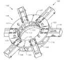
- FIG. 1is an orthogonal view of an exemplary embodiment of the preload sectional spider assembly.
- FIG. 2is a top view of the plates of the preload spider assembly of FIG. 1 .
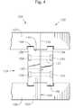
- FIG. 3is a side view of a joint of the preload spider assembly, taken along the 3 - 3 line.
- FIG. 4is a side view of a joint of the preload spider assembly of FIG. 1 , showing the gap between the clamping plates prior to apply a preload.
- spider support assembly 100is an assembly used to make up, or join, sections of riser pipe (not shown). Spider 100 is suspended over an opening on a drilling rig table (not shown) and dogs 102 located on spider 100 are used to support the weight of a first riser section (not shown) as a second riser section is stabbed into the first. A string of riser sections may be suspended below the first riser section.
- spider 100is 196′′ in diameter and weighs 45,000 pounds. Spider may be larger or smaller and may weigh more or less.
- spider support assembly 100comprises a first half ring 104 and a second half ring 105 .
- the half rings 104 , 105are joined together at seam 106 .
- Each half ring 104 , 105comprises an upper plate 107 and a lower plate 108 .
- Each plate 107 , 108is generally a flat plate having an inner diameter surface 112 .
- the round boremay be axially aligned with a wellbore (not shown).
- the outermost edge 116 of plates 107 , 108may have a generally round shape, or may have other shapes.
- Upper plate 107 and lower plate 108each rotated about the same axis, are stacked on top of each other to form each half ring 104 , 105 of support assembly 100 .
- Frame memberssuch as the support housings 118 of riser support dogs 102 , may be located between upper plate 107 and lower plate 108 to create a gap 110 (best seen in FIG. 4 ) between upper plate 107 and lower plate 108 .
- six support housings 118are located between upper plate 107 and lower plate 108 .
- Bolts 120may pass through upper plate 107 , through support housing 118 , and through lower plate 108 . Nuts (not shown) are then tightened onto bolts.
- threadsare tapped into support housing 118 and bolts 120 pass through upper plate 107 or lower plate 108 and are then tightened into support housing 118 .
- Some embodiments of the support assembly 100may have more than two plates 107 , 108 .
- a bolt-on gimbal support ring 122may be attached to the lower plate 108 for interfacing with the drilling rig platform (not shown).
- Various assembliesmay be attached between the plates 107 , 108 , such as dogs 102 used to support casing.
- various assembliesmay be attached above the top plate 107 including, for example, hydraulic actuators for joining sections of casing, grating for operators to stand on while operating the spider, and handrails.
- spider support assembly 100may be split into two or more sections 104 , 105 to facilitate transportation or to rapidly remove spider support assembly 100 while casing (not shown) is protruding through the bore of spider, such as under emergency conditions.
- Some embodimentsmay have plates that separate into more than two sections.
- Seam 106( FIG. 1 ) is generally located at a point where it will not interfere with hydraulic mechanisms or dogs 102 .
- each half ring 104 , 105has a c-shape. The edge surface 132 located at the end of each “c” butts against the edge surface 132 of an adjacent c-shaped half-plate to form a whole plate 104 , 105 having an o-shape.
- each seam 106 between first half ring 104 and second half ring 105comprises an edge surface 132 and a groove 134 .
- Groove 134is a slot in the upper face of lower plate 108 and in the lower face of upper plate 107 .
- Edge surface 132is the end piece that will press against an edge surface of the adjoining plate 107 , 108 .
- clamping assembly 136comprises two clamping plates 138 .
- Each clamping plate 138has a body having a front face 140 , a back face 142 , an upper surface 144 , a lower surface 146 , and one or more lips 148 .
- Lip 148is a flange protruding from upper surface 144 or lower surface 146 . Lip 148 protrudes a distance roughly equal to the depth of groove 134 , or may be slightly taller or slightly shorter than the depth of groove 134 .
- the width of lip 148may be slightly smaller or slightly larger than the width of groove 134 .
- lip 148fits in groove 134 , or in some embodiments may be force fit into groove 134 .
- each clamping plate 138 between the inside edge of lip 148 and front face 140is slightly smaller than the length between the inside edge of groove 134 and edge surface 132 .
- the distance from the inside edge of lip 148 to front face 140is approximately 0.015 to 0.030 inches less than the distance from the inside edge of groove 134 to edge surface 132 .
- clamping plate 138is attached to upper and lower plates by other means, such as by welding (not shown) or with bolts (not shown).
- clamping plateis attached such that a gap exists between front face 140 and a plane defined by edge face of plate, and the gap is drawn together when preload stress is applied to clamps, thus causing compressive forces against edge surfaces 132 .
- clamping platesmay be attached to the top surface of upper plate 107 or to the bottom surface of lower plate 108 .
- Clamping plate 138has smooth cylindrical holes 152 for receiving bolts 154 for attaching clamping plate 138 to an adjacent clamping plate 138 .
- the holes 152pass through the clamping plate 138 from the back face 142 to the front face 140 .
- the diameter of the smooth cylindrical holes 152is slightly larger than the diameter of the bolts 154 .
- Bolt holes 152may have a counter bore 160 for receiving bolt heads so that bolt heads do not protrude from clamping plate 138 when the bolts 154 are installed.
- Boltsare passed through the first clamping plate 138 , from the back face 142 to the front face 140 , such that the bolt threads (not shown) protrude from the front face 140 of the first clamping plate 138 and pass into the front face 140 of the second clamping plate 132 .
- Nuts 156may be attached to the threads of the bolts 154 to secure bolts and apply a load between the plates.
- counterbores 160are located on the back face 142 of the second clamping plate 132 so that nuts may be countersunk and thus not protrude from back face 142 of the second clamping plate.
- threadsare tapped into the second clamping plate 138 (not shown) and thus the bolts 154 directly engage threads of second clamping plate 138 rather than requiring nuts.
- compression between the platesis not generated by bolts.
- a compression devicesuch as a c-clamp (not shown) or a cam (not shown) may be used to press clamping plates toward each other.
- a compression devicesuch as a hydraulic actuator (not shown) may press the clamping plates and hold them in close proximity to each other while a rigid retainer (not shown) is installed to maintain the compression.
- a pin 162may pass through upper plate 107 or lower plate 108 into clamping plate 138 to prevent clamping plate 138 from falling out of position during transportation or installation. Pin 162 is generally not needed after the bolts 154 are tightened because compressive force exerted by clamping plate 138 on plates 107 and 108 prevent clamping plate 138 from falling out of position.
- each half ring 104 , 105 of spider assembly 100is assembled by placing support housings 118 between upper plate 107 and lower plate 108 .
- Clamping plate 138is installed by sliding lip 148 into grooves 134 .
- Two pins 162are inserted, one each through upper plate 107 and lower plate 108 into clamping plate 138 .
- Half ring 104has two clamping plates 138 —one at each end of the c-shape.
- the half rings 104 , 105 of spider assembly 100are joined by aligning end surfaces 132 .
- end surface 132 of first half ring 104is in contact with end surface 132 of second half ring 105 , but not under preload tension, there is a gap 164 between interior faces 140 of approximately 0.030 to 0.060 inches.
- Bolts 154are passed through bolt holes 152 of clamping plates 138 , and then tightened such as with nuts 156 . Torque is applied to bolts 154 until the gap 164 between interior faces 140 is reduced or eliminated. Torque could be, for example, 1000 foot pounds. In some embodiments, torque is applied until interior faces 140 contact each other. Thus edge surfaces 132 are thus preloaded against adjacent edge surfaces 132 .
- support assembly 100may support a string of casing weighing 500,000 pounds and have a deflection in the axial direction, at seam 106 , of less than 1 ⁇ 2′′. In some embodiments, deflection may 3/16′′ or less.
Landscapes
- Engineering & Computer Science (AREA)
- Life Sciences & Earth Sciences (AREA)
- Geology (AREA)
- Mining & Mineral Resources (AREA)
- Mechanical Engineering (AREA)
- Physics & Mathematics (AREA)
- Environmental & Geological Engineering (AREA)
- Fluid Mechanics (AREA)
- General Life Sciences & Earth Sciences (AREA)
- Geochemistry & Mineralogy (AREA)
- Earth Drilling (AREA)
Abstract
Description
Claims (20)
Priority Applications (5)
| Application Number | Priority Date | Filing Date | Title |
|---|---|---|---|
| US12/494,037US8322436B2 (en) | 2009-06-29 | 2009-06-29 | Split assembly attachment device |
| MYPI2010002937AMY149769A (en) | 2009-06-29 | 2010-06-21 | Split assembly attachment device |
| BRPI1001843-3ABRPI1001843A2 (en) | 2009-06-29 | 2010-06-22 | Riser Implant |
| EP10166737.6AEP2281997A3 (en) | 2009-06-29 | 2010-06-22 | Split tubular support device |
| AU2010202677AAU2010202677B2 (en) | 2009-06-29 | 2010-06-25 | Split assembly attachment device |
Applications Claiming Priority (1)
| Application Number | Priority Date | Filing Date | Title |
|---|---|---|---|
| US12/494,037US8322436B2 (en) | 2009-06-29 | 2009-06-29 | Split assembly attachment device |
Publications (2)
| Publication Number | Publication Date |
|---|---|
| US20100326666A1 US20100326666A1 (en) | 2010-12-30 |
| US8322436B2true US8322436B2 (en) | 2012-12-04 |
Family
ID=42671891
Family Applications (1)
| Application Number | Title | Priority Date | Filing Date |
|---|---|---|---|
| US12/494,037Active2031-03-26US8322436B2 (en) | 2009-06-29 | 2009-06-29 | Split assembly attachment device |
Country Status (5)
| Country | Link |
|---|---|
| US (1) | US8322436B2 (en) |
| EP (1) | EP2281997A3 (en) |
| AU (1) | AU2010202677B2 (en) |
| BR (1) | BRPI1001843A2 (en) |
| MY (1) | MY149769A (en) |
Cited By (12)
| Publication number | Priority date | Publication date | Assignee | Title |
|---|---|---|---|---|
| US20150167404A1 (en)* | 2013-12-18 | 2015-06-18 | Cameron International Corporation | Hang-Off Gimbal Assembly |
| WO2016061444A1 (en) | 2014-10-17 | 2016-04-21 | Hydril USA Distribution LLC | High pressure subsea blowout preventer system |
| US20160319622A1 (en)* | 2015-05-01 | 2016-11-03 | Hydril Usa Distribution, Llc | Hydraulic Re-configurable and Subsea Repairable Control System for Deepwater Blow-out Preventers |
| US9528340B2 (en) | 2014-12-17 | 2016-12-27 | Hydrill USA Distribution LLC | Solenoid valve housings for blowout preventer |
| US20170175456A1 (en)* | 2015-12-21 | 2017-06-22 | Integral Oilfield Solutions | Universal injection head system and method |
| US9759018B2 (en) | 2014-12-12 | 2017-09-12 | Hydril USA Distribution LLC | System and method of alignment for hydraulic coupling |
| US9803448B2 (en) | 2014-09-30 | 2017-10-31 | Hydril Usa Distribution, Llc | SIL rated system for blowout preventer control |
| US9989975B2 (en) | 2014-11-11 | 2018-06-05 | Hydril Usa Distribution, Llc | Flow isolation for blowout preventer hydraulic control systems |
| US10196871B2 (en) | 2014-09-30 | 2019-02-05 | Hydril USA Distribution LLC | Sil rated system for blowout preventer control |
| US10202839B2 (en) | 2014-12-17 | 2019-02-12 | Hydril USA Distribution LLC | Power and communications hub for interface between control pod, auxiliary subsea systems, and surface controls |
| US10876369B2 (en) | 2014-09-30 | 2020-12-29 | Hydril USA Distribution LLC | High pressure blowout preventer system |
| US12180789B2 (en) | 2020-03-24 | 2024-12-31 | Weatherford Technology Holdings, Llc | Spiders capable of handling well components of multiple sizes |
Families Citing this family (1)
| Publication number | Priority date | Publication date | Assignee | Title |
|---|---|---|---|---|
| US11156038B1 (en)* | 2020-08-12 | 2021-10-26 | Forum Us, Inc. | Split bowl wear bushing |
Citations (31)
| Publication number | Priority date | Publication date | Assignee | Title |
|---|---|---|---|---|
| US2591763A (en)* | 1952-04-08 | safety clamp fob dkill collars | ||
| US2721581A (en)* | 1951-10-19 | 1955-10-25 | Dresser Ind | Pipe repair sleeve |
| US3029095A (en)* | 1955-08-18 | 1962-04-10 | Garrett Corp | Flange connecting clamp |
| US3414950A (en)* | 1967-04-03 | 1968-12-10 | Leon F. Phariss | Eccentric pipe welding clamp |
| US3512229A (en)* | 1968-08-16 | 1970-05-19 | Leon F Phariss | Outside pipe lineup clamp |
| US3675278A (en)* | 1970-07-30 | 1972-07-11 | Thurman O Powell | Combination elevator and spider |
| US3920232A (en)* | 1974-07-16 | 1975-11-18 | Julius Clark | Apparatus for aligning pipe ends |
| US3934318A (en)* | 1973-10-02 | 1976-01-27 | Hubert Joseph Mertens | Pipe clip |
| US4120520A (en)* | 1977-05-04 | 1978-10-17 | Vetco, Inc. | Lockable rigid connector for pipe and method of making the same |
| US4168853A (en)* | 1977-06-08 | 1979-09-25 | Vetco, Inc. | Shiftable ring gasket retainer for flanged connectors |
| US4209066A (en)* | 1978-11-17 | 1980-06-24 | Watson Barry R | Method and apparatus for running tubular goods into and out of a borehole |
| US4381584A (en)* | 1980-12-15 | 1983-05-03 | Bilco Tools, Inc. | Dual string spider |
| US4491346A (en)* | 1982-11-01 | 1985-01-01 | Dril-Quip, Inc. | Apparatus for releasably connecting tubular members in end-to-end relation |
| US6045296A (en)* | 1996-07-09 | 2000-04-04 | Abb Vetco Gray Inc. | Tension ring for riser |
| US6227587B1 (en)* | 2000-02-07 | 2001-05-08 | Emma Dee Gray | Combined well casing spider and elevator |
| US6321843B2 (en)* | 1998-07-23 | 2001-11-27 | Cooper Cameron Corporation | Preloading type connector |
| US6330918B1 (en)* | 1999-02-27 | 2001-12-18 | Abb Vetco Gray, Inc. | Automated dog-type riser make-up device and method of use |
| US6394201B1 (en)* | 1999-10-04 | 2002-05-28 | Universe Machine Corporation | Tubing spider |
| US6494273B1 (en)* | 1998-05-12 | 2002-12-17 | Richard Martin | Elevator for supporting an elongate member such as a drill pipe |
| US6695356B2 (en)* | 2001-11-19 | 2004-02-24 | Cooper Cameron | Connector for securing conduits |
| US6892835B2 (en)* | 2002-07-29 | 2005-05-17 | Weatherford/Lamb, Inc. | Flush mounted spider |
| US7044216B2 (en)* | 2003-11-05 | 2006-05-16 | Grant Prideco, L.P. | Large diameter flush-joint pipe handling system |
| US7055609B2 (en)* | 2002-06-03 | 2006-06-06 | Schlumberger Technology Corporation | Handling and assembly equipment and method |
| US20070125541A1 (en)* | 2005-12-02 | 2007-06-07 | Halliburton Energy Services, Inc. | Threaded connector for well servicing applications |
| US20070267197A1 (en)* | 2006-05-19 | 2007-11-22 | Vetco Gray Inc. | Rapid Makeup Drilling Riser |
| US7331395B2 (en)* | 2005-08-23 | 2008-02-19 | Vetco Gray Inc. | Riser make-up tool |
| US7360603B2 (en)* | 2004-11-30 | 2008-04-22 | Varco I/P, Inc. | Methods and apparatuses for wellbore operations |
| US7370707B2 (en)* | 2003-04-04 | 2008-05-13 | Weatherford/Lamb, Inc. | Method and apparatus for handling wellbore tubulars |
| US7614453B2 (en)* | 2006-06-01 | 2009-11-10 | Cameron International Corporation | Stress distributing wellhead connector |
| US20110158748A1 (en)* | 2008-06-04 | 2011-06-30 | Subsea 7 Ltd | Apparatus and method for use in laying pipe on the sea floor |
| US8020626B2 (en)* | 2008-05-02 | 2011-09-20 | Dale Francis | Torque wrench system having multiple torque stations |
Family Cites Families (1)
| Publication number | Priority date | Publication date | Assignee | Title |
|---|---|---|---|---|
| US4199847A (en)* | 1979-01-29 | 1980-04-29 | Armco Inc. | Well riser support having elastomeric bearings |
- 2009
- 2009-06-29USUS12/494,037patent/US8322436B2/enactiveActive
- 2010
- 2010-06-21MYMYPI2010002937Apatent/MY149769A/enunknown
- 2010-06-22EPEP10166737.6Apatent/EP2281997A3/ennot_activeWithdrawn
- 2010-06-22BRBRPI1001843-3Apatent/BRPI1001843A2/enactiveSearch and Examination
- 2010-06-25AUAU2010202677Apatent/AU2010202677B2/ennot_activeCeased
Patent Citations (36)
| Publication number | Priority date | Publication date | Assignee | Title |
|---|---|---|---|---|
| US2591763A (en)* | 1952-04-08 | safety clamp fob dkill collars | ||
| US2721581A (en)* | 1951-10-19 | 1955-10-25 | Dresser Ind | Pipe repair sleeve |
| US3029095A (en)* | 1955-08-18 | 1962-04-10 | Garrett Corp | Flange connecting clamp |
| US3414950A (en)* | 1967-04-03 | 1968-12-10 | Leon F. Phariss | Eccentric pipe welding clamp |
| US3512229A (en)* | 1968-08-16 | 1970-05-19 | Leon F Phariss | Outside pipe lineup clamp |
| US3675278A (en)* | 1970-07-30 | 1972-07-11 | Thurman O Powell | Combination elevator and spider |
| US3934318A (en)* | 1973-10-02 | 1976-01-27 | Hubert Joseph Mertens | Pipe clip |
| US3920232A (en)* | 1974-07-16 | 1975-11-18 | Julius Clark | Apparatus for aligning pipe ends |
| US4120520A (en)* | 1977-05-04 | 1978-10-17 | Vetco, Inc. | Lockable rigid connector for pipe and method of making the same |
| US4168853A (en)* | 1977-06-08 | 1979-09-25 | Vetco, Inc. | Shiftable ring gasket retainer for flanged connectors |
| US4209066A (en)* | 1978-11-17 | 1980-06-24 | Watson Barry R | Method and apparatus for running tubular goods into and out of a borehole |
| US4381584A (en)* | 1980-12-15 | 1983-05-03 | Bilco Tools, Inc. | Dual string spider |
| US4491346A (en)* | 1982-11-01 | 1985-01-01 | Dril-Quip, Inc. | Apparatus for releasably connecting tubular members in end-to-end relation |
| US6045296A (en)* | 1996-07-09 | 2000-04-04 | Abb Vetco Gray Inc. | Tension ring for riser |
| US6494273B1 (en)* | 1998-05-12 | 2002-12-17 | Richard Martin | Elevator for supporting an elongate member such as a drill pipe |
| US6321843B2 (en)* | 1998-07-23 | 2001-11-27 | Cooper Cameron Corporation | Preloading type connector |
| US6330918B1 (en)* | 1999-02-27 | 2001-12-18 | Abb Vetco Gray, Inc. | Automated dog-type riser make-up device and method of use |
| US6394201B1 (en)* | 1999-10-04 | 2002-05-28 | Universe Machine Corporation | Tubing spider |
| US6227587B1 (en)* | 2000-02-07 | 2001-05-08 | Emma Dee Gray | Combined well casing spider and elevator |
| US6905148B2 (en)* | 2001-11-19 | 2005-06-14 | Cooper Cameron Corporation | Connector for securing conduits |
| US6695356B2 (en)* | 2001-11-19 | 2004-02-24 | Cooper Cameron | Connector for securing conduits |
| US7055609B2 (en)* | 2002-06-03 | 2006-06-06 | Schlumberger Technology Corporation | Handling and assembly equipment and method |
| US6892835B2 (en)* | 2002-07-29 | 2005-05-17 | Weatherford/Lamb, Inc. | Flush mounted spider |
| US7370707B2 (en)* | 2003-04-04 | 2008-05-13 | Weatherford/Lamb, Inc. | Method and apparatus for handling wellbore tubulars |
| US7044216B2 (en)* | 2003-11-05 | 2006-05-16 | Grant Prideco, L.P. | Large diameter flush-joint pipe handling system |
| US7360603B2 (en)* | 2004-11-30 | 2008-04-22 | Varco I/P, Inc. | Methods and apparatuses for wellbore operations |
| US7963336B2 (en)* | 2005-08-23 | 2011-06-21 | Vetco Gray Inc. | Preloaded riser coupling system |
| US7331395B2 (en)* | 2005-08-23 | 2008-02-19 | Vetco Gray Inc. | Riser make-up tool |
| US7337848B2 (en)* | 2005-08-23 | 2008-03-04 | Vetco Gray Inc. | Preloaded riser coupling system |
| US7975768B2 (en)* | 2005-08-23 | 2011-07-12 | Vetco Gray Inc. | Riser joint coupling |
| US20070125541A1 (en)* | 2005-12-02 | 2007-06-07 | Halliburton Energy Services, Inc. | Threaded connector for well servicing applications |
| US20070267197A1 (en)* | 2006-05-19 | 2007-11-22 | Vetco Gray Inc. | Rapid Makeup Drilling Riser |
| US7686087B2 (en)* | 2006-05-19 | 2010-03-30 | Vetco Gray Inc. | Rapid makeup drilling riser |
| US7614453B2 (en)* | 2006-06-01 | 2009-11-10 | Cameron International Corporation | Stress distributing wellhead connector |
| US8020626B2 (en)* | 2008-05-02 | 2011-09-20 | Dale Francis | Torque wrench system having multiple torque stations |
| US20110158748A1 (en)* | 2008-06-04 | 2011-06-30 | Subsea 7 Ltd | Apparatus and method for use in laying pipe on the sea floor |
Cited By (16)
| Publication number | Priority date | Publication date | Assignee | Title |
|---|---|---|---|---|
| US9284796B2 (en)* | 2013-12-18 | 2016-03-15 | Cameron International Corporation | Hang-off gimbal assembly |
| US20150167404A1 (en)* | 2013-12-18 | 2015-06-18 | Cameron International Corporation | Hang-Off Gimbal Assembly |
| US10876369B2 (en) | 2014-09-30 | 2020-12-29 | Hydril USA Distribution LLC | High pressure blowout preventer system |
| US10196871B2 (en) | 2014-09-30 | 2019-02-05 | Hydril USA Distribution LLC | Sil rated system for blowout preventer control |
| US9803448B2 (en) | 2014-09-30 | 2017-10-31 | Hydril Usa Distribution, Llc | SIL rated system for blowout preventer control |
| WO2016061444A1 (en) | 2014-10-17 | 2016-04-21 | Hydril USA Distribution LLC | High pressure subsea blowout preventer system |
| US10048673B2 (en) | 2014-10-17 | 2018-08-14 | Hydril Usa Distribution, Llc | High pressure blowout preventer system |
| US9989975B2 (en) | 2014-11-11 | 2018-06-05 | Hydril Usa Distribution, Llc | Flow isolation for blowout preventer hydraulic control systems |
| US9759018B2 (en) | 2014-12-12 | 2017-09-12 | Hydril USA Distribution LLC | System and method of alignment for hydraulic coupling |
| US10202839B2 (en) | 2014-12-17 | 2019-02-12 | Hydril USA Distribution LLC | Power and communications hub for interface between control pod, auxiliary subsea systems, and surface controls |
| US9528340B2 (en) | 2014-12-17 | 2016-12-27 | Hydrill USA Distribution LLC | Solenoid valve housings for blowout preventer |
| US9828824B2 (en)* | 2015-05-01 | 2017-11-28 | Hydril Usa Distribution, Llc | Hydraulic re-configurable and subsea repairable control system for deepwater blow-out preventers |
| US20160319622A1 (en)* | 2015-05-01 | 2016-11-03 | Hydril Usa Distribution, Llc | Hydraulic Re-configurable and Subsea Repairable Control System for Deepwater Blow-out Preventers |
| US20170175456A1 (en)* | 2015-12-21 | 2017-06-22 | Integral Oilfield Solutions | Universal injection head system and method |
| US10428605B2 (en)* | 2015-12-21 | 2019-10-01 | Integral Oilfield Solutions, Llc | Universal injection head system and method |
| US12180789B2 (en) | 2020-03-24 | 2024-12-31 | Weatherford Technology Holdings, Llc | Spiders capable of handling well components of multiple sizes |
Also Published As
| Publication number | Publication date |
|---|---|
| AU2010202677B2 (en) | 2013-07-25 |
| EP2281997A3 (en) | 2017-04-12 |
| EP2281997A2 (en) | 2011-02-09 |
| AU2010202677A1 (en) | 2011-01-20 |
| BRPI1001843A2 (en) | 2015-07-14 |
| MY149769A (en) | 2013-10-14 |
| US20100326666A1 (en) | 2010-12-30 |
Similar Documents
| Publication | Publication Date | Title |
|---|---|---|
| US8322436B2 (en) | Split assembly attachment device | |
| US8096540B2 (en) | Tension ring lifting assembly | |
| AU2012200881B2 (en) | Pipe Sealing | |
| US5951066A (en) | Connecting system for wellhead components | |
| GB2515418B (en) | Seal sub system | |
| US20070114039A1 (en) | Rotatable flange adapter | |
| US7850213B2 (en) | Coupling with crossable means for couplings to connect endportions of pipes and valves | |
| EP2573315B1 (en) | Centralizer | |
| GB2453567A (en) | Clamp having pre-stressed spring elements between outer clamp shell and inner clamp member | |
| US20090321066A1 (en) | Packer Insert for Sealing on Multiple Items Used in a Wellbore | |
| US9068403B2 (en) | Riser tensioner frame assembly | |
| EP2831478B1 (en) | Apparatus for improving flanged connections | |
| US11867001B2 (en) | System and method for connecting a termination body to a portion of a riser | |
| JP5522460B2 (en) | Fasteners used in main column replacement equipment for steel pipe towers | |
| GB2494993A (en) | Deployment collar for a centralizer |
Legal Events
| Date | Code | Title | Description |
|---|---|---|---|
| AS | Assignment | Owner name:VETCO GRAY INC., TEXAS Free format text:ASSIGNMENT OF ASSIGNORS INTEREST;ASSIGNOR:MAA, TSORNG-JONG;REEL/FRAME:022889/0273 Effective date:20090626 | |
| STCF | Information on status: patent grant | Free format text:PATENTED CASE | |
| FPAY | Fee payment | Year of fee payment:4 | |
| MAFP | Maintenance fee payment | Free format text:PAYMENT OF MAINTENANCE FEE, 8TH YEAR, LARGE ENTITY (ORIGINAL EVENT CODE: M1552); ENTITY STATUS OF PATENT OWNER: LARGE ENTITY Year of fee payment:8 | |
| AS | Assignment | Owner name:VETCO GRAY, LLC, DELAWARE Free format text:CHANGE OF NAME;ASSIGNOR:VETCO GRAY INC.;REEL/FRAME:057616/0655 Effective date:20170516 | |
| AS | Assignment | Owner name:HYDRIL USA DISTRIBUTION LLC, TEXAS Free format text:ASSIGNMENT OF ASSIGNORS INTEREST;ASSIGNOR:VETCO GRAY, LLC;REEL/FRAME:057630/0690 Effective date:20210901 | |
| MAFP | Maintenance fee payment | Free format text:PAYMENT OF MAINTENANCE FEE, 12TH YEAR, LARGE ENTITY (ORIGINAL EVENT CODE: M1553); ENTITY STATUS OF PATENT OWNER: LARGE ENTITY Year of fee payment:12 |