US8322342B2 - Operative arm support - Google Patents
Operative arm supportDownload PDFInfo
- Publication number
- US8322342B2 US8322342B2US12/508,389US50838909AUS8322342B2US 8322342 B2US8322342 B2US 8322342B2US 50838909 AUS50838909 AUS 50838909AUS 8322342 B2US8322342 B2US 8322342B2
- Authority
- US
- United States
- Prior art keywords
- limb
- positioner
- axis
- arm
- support
- Prior art date
- Legal status (The legal status is an assumption and is not a legal conclusion. Google has not performed a legal analysis and makes no representation as to the accuracy of the status listed.)
- Expired - Fee Related, expires
Links
- 230000007246mechanismEffects0.000claimsabstractdescription24
- 210000003414extremityAnatomy0.000claimsdescription202
- 210000000245forearmAnatomy0.000claimsdescription25
- 239000004744fabricSubstances0.000claimsdescription8
- 125000006850spacer groupChemical group0.000claimsdescription6
- 239000006260foamSubstances0.000claimsdescription2
- 210000003141lower extremityAnatomy0.000claims1
- 210000001503jointAnatomy0.000description14
- 238000000034methodMethods0.000description10
- 238000001356surgical procedureMethods0.000description7
- 230000008859changeEffects0.000description3
- IDLFZVILOHSSID-OVLDLUHVSA-NcorticotropinChemical compoundC([C@@H](C(=O)N[C@@H](CO)C(=O)N[C@@H](CCSC)C(=O)N[C@@H](CCC(O)=O)C(=O)N[C@@H](CC=1NC=NC=1)C(=O)N[C@@H](CC=1C=CC=CC=1)C(=O)N[C@@H](CCCNC(N)=N)C(=O)N[C@@H](CC=1C2=CC=CC=C2NC=1)C(=O)NCC(=O)N[C@@H](CCCCN)C(=O)N1[C@@H](CCC1)C(=O)N[C@@H](C(C)C)C(=O)NCC(=O)N[C@@H](CCCCN)C(=O)N[C@@H](CCCCN)C(=O)N[C@@H](CCCNC(N)=N)C(=O)N[C@@H](CCCNC(N)=N)C(=O)N1[C@@H](CCC1)C(=O)N[C@@H](C(C)C)C(=O)N[C@@H](CCCCN)C(=O)N[C@@H](C(C)C)C(=O)N[C@@H](CC=1C=CC(O)=CC=1)C(=O)N1[C@@H](CCC1)C(=O)N[C@@H](CC(N)=O)C(=O)NCC(=O)N[C@@H](C)C(=O)N[C@@H](CCC(O)=O)C(=O)N[C@@H](CC(O)=O)C(=O)N[C@@H](CCC(O)=O)C(=O)N[C@@H](CO)C(=O)N[C@@H](C)C(=O)N[C@@H](CCC(O)=O)C(=O)N[C@@H](C)C(=O)N[C@@H](CC=1C=CC=CC=1)C(=O)N1[C@@H](CCC1)C(=O)N[C@@H](CC(C)C)C(=O)N[C@@H](CCC(O)=O)C(=O)N[C@@H](CC=1C=CC=CC=1)C(O)=O)NC(=O)[C@@H](N)CO)C1=CC=C(O)C=C1IDLFZVILOHSSID-OVLDLUHVSA-N0.000description3
- 230000008569processEffects0.000description3
- 230000008439repair processEffects0.000description3
- 238000010276constructionMethods0.000description2
- 230000036512infertilityEffects0.000description2
- 210000000707wristAnatomy0.000description2
- 230000006978adaptationEffects0.000description1
- 238000013459approachMethods0.000description1
- 230000008901benefitEffects0.000description1
- 230000000994depressogenic effectEffects0.000description1
- 230000003902lesionEffects0.000description1
- 230000004048modificationEffects0.000description1
- 238000012986modificationMethods0.000description1
- 230000009467reductionEffects0.000description1
- 230000000284resting effectEffects0.000description1
- 210000000513rotator cuffAnatomy0.000description1
- 210000000323shoulder jointAnatomy0.000description1
- 239000000126substanceSubstances0.000description1
Images


Classifications
- A—HUMAN NECESSITIES
- A61—MEDICAL OR VETERINARY SCIENCE; HYGIENE
- A61G—TRANSPORT, PERSONAL CONVEYANCES, OR ACCOMMODATION SPECIALLY ADAPTED FOR PATIENTS OR DISABLED PERSONS; OPERATING TABLES OR CHAIRS; CHAIRS FOR DENTISTRY; FUNERAL DEVICES
- A61G13/00—Operating tables; Auxiliary appliances therefor
- A61G13/10—Parts, details or accessories
- A61G13/12—Rests specially adapted therefor; Arrangements of patient-supporting surfaces
- A—HUMAN NECESSITIES
- A61—MEDICAL OR VETERINARY SCIENCE; HYGIENE
- A61G—TRANSPORT, PERSONAL CONVEYANCES, OR ACCOMMODATION SPECIALLY ADAPTED FOR PATIENTS OR DISABLED PERSONS; OPERATING TABLES OR CHAIRS; CHAIRS FOR DENTISTRY; FUNERAL DEVICES
- A61G13/00—Operating tables; Auxiliary appliances therefor
- A61G13/0036—Orthopaedic operating tables
- A61G13/0072—Orthopaedic operating tables specially adapted for shoulder surgeries
- A—HUMAN NECESSITIES
- A61—MEDICAL OR VETERINARY SCIENCE; HYGIENE
- A61G—TRANSPORT, PERSONAL CONVEYANCES, OR ACCOMMODATION SPECIALLY ADAPTED FOR PATIENTS OR DISABLED PERSONS; OPERATING TABLES OR CHAIRS; CHAIRS FOR DENTISTRY; FUNERAL DEVICES
- A61G13/00—Operating tables; Auxiliary appliances therefor
- A61G13/10—Parts, details or accessories
- A61G13/12—Rests specially adapted therefor; Arrangements of patient-supporting surfaces
- A61G13/1205—Rests specially adapted therefor; Arrangements of patient-supporting surfaces for specific parts of the body
- A61G13/1235—Arms
- A—HUMAN NECESSITIES
- A61—MEDICAL OR VETERINARY SCIENCE; HYGIENE
- A61G—TRANSPORT, PERSONAL CONVEYANCES, OR ACCOMMODATION SPECIALLY ADAPTED FOR PATIENTS OR DISABLED PERSONS; OPERATING TABLES OR CHAIRS; CHAIRS FOR DENTISTRY; FUNERAL DEVICES
- A61G13/00—Operating tables; Auxiliary appliances therefor
- A61G13/10—Parts, details or accessories
- A61G13/12—Rests specially adapted therefor; Arrangements of patient-supporting surfaces
- A61G13/1205—Rests specially adapted therefor; Arrangements of patient-supporting surfaces for specific parts of the body
- A61G13/1245—Knees, upper or lower legs
- A—HUMAN NECESSITIES
- A61—MEDICAL OR VETERINARY SCIENCE; HYGIENE
- A61G—TRANSPORT, PERSONAL CONVEYANCES, OR ACCOMMODATION SPECIALLY ADAPTED FOR PATIENTS OR DISABLED PERSONS; OPERATING TABLES OR CHAIRS; CHAIRS FOR DENTISTRY; FUNERAL DEVICES
- A61G13/00—Operating tables; Auxiliary appliances therefor
- A61G13/10—Parts, details or accessories
- A61G13/12—Rests specially adapted therefor; Arrangements of patient-supporting surfaces
- A61G13/1205—Rests specially adapted therefor; Arrangements of patient-supporting surfaces for specific parts of the body
- A61G13/1255—Shoulders
- A—HUMAN NECESSITIES
- A61—MEDICAL OR VETERINARY SCIENCE; HYGIENE
- A61G—TRANSPORT, PERSONAL CONVEYANCES, OR ACCOMMODATION SPECIALLY ADAPTED FOR PATIENTS OR DISABLED PERSONS; OPERATING TABLES OR CHAIRS; CHAIRS FOR DENTISTRY; FUNERAL DEVICES
- A61G13/00—Operating tables; Auxiliary appliances therefor
- A61G13/10—Parts, details or accessories
- A61G13/12—Rests specially adapted therefor; Arrangements of patient-supporting surfaces
- A61G13/128—Rests specially adapted therefor; Arrangements of patient-supporting surfaces with mechanical surface adaptations
- A61G13/1295—Rests specially adapted therefor; Arrangements of patient-supporting surfaces with mechanical surface adaptations having alignment devices for the patient's body
- A—HUMAN NECESSITIES
- A61—MEDICAL OR VETERINARY SCIENCE; HYGIENE
- A61G—TRANSPORT, PERSONAL CONVEYANCES, OR ACCOMMODATION SPECIALLY ADAPTED FOR PATIENTS OR DISABLED PERSONS; OPERATING TABLES OR CHAIRS; CHAIRS FOR DENTISTRY; FUNERAL DEVICES
- A61G2200/00—Information related to the kind of patient or his position
- A61G2200/30—Specific positions of the patient
- A61G2200/32—Specific positions of the patient lying
- A61G2200/322—Specific positions of the patient lying lateral
- A—HUMAN NECESSITIES
- A61—MEDICAL OR VETERINARY SCIENCE; HYGIENE
- A61G—TRANSPORT, PERSONAL CONVEYANCES, OR ACCOMMODATION SPECIALLY ADAPTED FOR PATIENTS OR DISABLED PERSONS; OPERATING TABLES OR CHAIRS; CHAIRS FOR DENTISTRY; FUNERAL DEVICES
- A61G2200/00—Information related to the kind of patient or his position
- A61G2200/30—Specific positions of the patient
- A61G2200/34—Specific positions of the patient sitting
Definitions
- the present disclosureis related to a limb support for surgical applications. More specifically, the present disclosure is related to an operative arm support suitable for supporting an arm during surgical operations on the shoulder of an individual.
- Surgical limb holdersare used to support a patient's extremities to allow a surgeon to have access to surgical sites.
- the limbis often repositioned multiple times during the surgical process to allow the surgeon varying access to the joint supporting the limb. Because the surgical process requires access to the joint from multiple directions to allow the surgeon complete access to the joint, limb must be repositioned to change the angle from which the surgeon approaches the joint during the surgery.
- a surgeonmust have both anterior and posterior access to the shoulder joint while the arm remains supported.
- a positioning device that is adjusted during surgerypresents issues related to sterility during the process.
- the controls for adjustmentare positioned outside the sterile field and require a surgery technician to assist the surgeon in positioning. This sometimes results in time consuming repositioning or a less than optimal position. This also discourages the repositioning of the limb, thereby reducing the ability of the surgeon to have optimal access to the joint.
- the adjustment mechanismis within the sterile field, then provisions must be made for maintaining sterility during the procedure. Also, the device must be capable of being sterilized by steam or chemicals, for example.
- a limb positionercomprises a multi-axis positioner, a lock supporting the multi-axis positioner, and a limb support.
- the multi-axis positionerincludes a variable resistance locking mechanism adjustable to vary the resistance of each axis to movement, the multi-axis positioner including a first pivot pivotable about a first axis.
- the lockis movable between a first position wherein the multi-axis positioner is movable relative to the lock and a second position wherein the multi-axis positioner is fixed relative to the lock.
- the limb supportis supported by the multi-axis positioner and includes a frame configured to support a limb such that a joint of the limb is indexed to the first pivot for movement of the limb about the joint.
- variable resistance locking mechanismis adjustable to a position wherein movement about each axis of the multi-axis positioner is resisted at a rate that prevents a limb supported on the limb positioner from movement under the weight of the limb while permitting a user to adjust the position of the limb by applying sufficient manual force to overcome the resistance.
- the locking mechanismmay also be adjusted to lock the limb positioner such that the limb positioner is not manually adjustable.
- the multi-axis positionercomprises first and second spherical joints, first and second arms coupled to each of the respective first and second spherical joints, and a hub interposed between the first and second arms, the first arm pivotable relative to the second arm.
- the multi-axis positionermay include a handle positioned on the hub and actuable by user, the handle operable to vary the resistance to movement of the first and second spherical joints and the hub.
- pivoting of the limb support about the first axis of the first pivotpermits an extremity of the limb to move about the joint without causing movement of an axis of the joint.
- the limb supportedis an arm and the joint is an elbow and movement of the forearm about the elbow does not cause movement of the patient's upper arm connected to the elbow.
- the limb positionerfurther comprises a disposable dressing secured to the limb support.
- the disposable dressingmay include means for securing the forearm of the patient to the limb support.
- the means for securing the forearm of the patient to the limb supportincludes a plurality of straps and fasteners, the straps positionable to overlie the forearm and the fasteners securing the straps to maintain the forearm positioned on the limb support.
- the disposable dressingis secured to the limb support and includes a plurality of straps, each strap including a first fastener, each of the first fasteners engageable with a second fastener of the disposable dressing such that the straps are positioned to secure the limb of a patient to the limb support.
- the first fastenercomprises a first portion of a hook-and-loop fabric fastener and the second fastener comprises a second portion of the hook-and-loop fabric fastener.
- the limb supportmay comprise a frame including a mount, a cross-bar, a first extension, and a second extension.
- the mountmay have a longitudinal length defining a longitudinal axis.
- the cross-barmay be coupled to the mount with the cross-bar having a longitudinal length defining a longitudinal axis.
- the first extensionmay have a longitudinal length defining a longitudinal axis and may be coupled to the cross-bar at a position spaced apart from the mount.
- the first extensionextends from the cross-bar in a cantilevered configuration such that the longitudinal axis of the first extension may be generally perpendicular to both the longitudinal axis of the cross-bar and the longitudinal axis of a the mount.
- the second extensionmay have a longitudinal length defining a longitudinal axis and may be coupled to the cross-bar at a position spaced apart from the mount and opposite the first extension.
- the second extensionextends from the cross-bar in a cantilevered configuration such that the longitudinal axis of the second extension may be generally perpendicular to both the longitudinal axis of the cross-bar and the longitudinal axis of a the mount.
- the longitudinal axis of the second extensionmay be generally parallel to the longitudinal axis of the first extension, a space being formed between the first extension and the second extension.
- the mounthas a cavity sized to be received on a supporting structure for the mount.
- the limb supportmay further comprise a spacer between the cross-bar and each of the first and second extensions.
- the longitudinal axes of the first and second extensionsare spaced apart from the longitudinal axis of the cross-bar such that the longitudinal axes of the first and second extensions do not intersect the longitudinal axis of the cross-bar.
- the limb supportmay be sterilizable.
- the disposable dressingmay be positioned on the first and second extensions, the disposable dressing including a plurality of flexible restraints for securing the limb of a patient to the limb support.
- the disposable dressingmay include a flexible base having a bottom surface and a top surface, an envelope having an open end, the envelope sized to enclose the first and second extensions, a fastener securing the disposable dressing to the frame, a flap coupled to the flexible base, the flap positionable to overlie a limb supported on the flexible base, and a plurality of straps to secure the flap over the limb and secure the limb to the limb support.
- the strapsare secured by a hook-and-loop fastener.
- the disposable dressingcomprises foam.
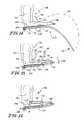
- FIG. 1is a front view of an embodiment of an limb positioner
- FIG. 2is a side view of the limb positioner of FIG. 1 ;
- FIG. 3is a side view of a portion of another embodiment of a limb positioner, FIG. 3 showing an alternative embodiment of a socket of a ball joint;
- FIG. 4is a front view of a ball joint including the socket of FIG. 3 ;
- FIG. 5is a side view of the ball joint of FIG. 4 with the ball rotated 90 degrees from the position shown in FIG. 4 ;
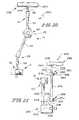
- FIG. 6is a side view of another embodiment of a limb positioner
- FIG. 7is a side view of yet another embodiment of a limb positioner
- FIG. 8is a side view of yet still another embodiment of a limb positioner
- FIG. 9is a side view of another embodiment of a limb positioner
- FIG. 10is a front view of the embodiment of FIG. 1 being manually moved to adjust the position of a limb support of the limp positioner;
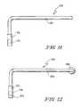
- FIG. 11is a side view of an embodiment of a limb support
- FIG. 12is a side view of yet another embodiment of a limb support
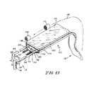
- FIG. 13is a perspective view of a limb support of the embodiment of FIG. 1 , the limb support engaged with a disposable dressing;
- FIGS. 14-16are side views of the limb support and dressing of FIG. 13 during various steps of engagement with the forearm of a patient, the limb support and dressing securing the forearm of the patient;
- FIG. 17is a perspective view of another embodiment of a limb support
- FIG. 18is a perspective view of yet another embodiment of a limb support
- FIG. 19is a perspective view of still yet another embodiment of a limb support
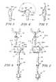
- FIG. 20is a front view of yet another embodiment of a limb positioner
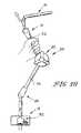
- FIG. 21is a side view of still yet another embodiment of a limb positioner.
- FIGS. 22-28are side views of various embodiments of limb positioners engaged with patient support apparatuses and supporting the forearm of patient.
- FIGS. 1 and 2An embodiment of a limb positioner 10 , illustratively embodied as an operative arm support is shown in FIGS. 1 and 2 .
- a commercial embodiment of the illustrative embodimentis a part numb A-92000 positioner available from Allen Medical Systems, Acton, Mass.
- the limb positioner 10includes a rail clamp 12 , a multi-axis positioner 14 , and a limb support 16 that is adjustable relative to the multi-axis positioner 14 through a ball joint 18 .
- the limb positioner 10includes a release mechanism 20 that is actuable by a user to release a plurality of joints 18 , 22 , and 24 to allow the limb positioner 10 to be re-positioned.
- the illustrative limb positioner 10may be used to position a limb for any of a number of procedures.
- the illustrative embodimentis especially effective for rotator cuff repair, SLAP lesion repair, Bankart repair, and capsulear release.
- the rail clamp 12has a body 26 that forms a t-slot 28 .
- the rail clamp 12further includes a lock 30 having a threaded axle 32 received into the body 26 .
- the threaded axle 32is coupled to a grip 34 movable by a user to rotate the threaded axle 32 into and out of the body 26 .
- the rail clamp 12is received onto a rail of a surgical table with the rail of the surgical to be engaged by the t-slot 28 of the rail clamp 12 .
- the threaded axle 32extends through the body 26 to engage the rail of the surgical table to lock the rail to 12 to the rail of the surgical table.
- the t-slot 28is sized such that the rail clamp 12 may be connected a rail of a surgical table over a drape so that the limb positioner 10 may be completely positioned within the sterile field.
- the multi-axis positioner 14includes a support 36 having a stem 38 received into the rail clamp 12 .
- the stem 38is coupled to a ball 40 received in a 42 to form ball joint 24 .
- An arm 43is coupled to the socket 42 at one end and a hub 46 of release mechanism 20 at the opposite end.
- Release mechanism 20further includes a second hub 48 pivotably coupled to hub 46 so that hub 46 and hub 48 move relative to each other with rotation about an axis 50 common to both hubs 46 and 48 .
- Release mechanism 20further includes a handle 44 having a plurality of grips 76 which may be gripped by a user to rotate handle 44 about axis 50 .
- a socket 54 of ball joint 18is coupled to arm 52 and receives a ball 56 .
- a mounting stem 58is coupled to ball 56 and extends there from to support a limb support 16 having a mount 74 received on mounting stem 58 .
- Both ball joint 18 and ball joint 24are configured to have multiple degrees of freedom.
- ball joint 18is movable as indicated by arrow 86 about an imaginary axis 88 as shown in FIG. 1 .
- ball 56is also rotatable about an axis 90 as indicated by arrow 82 .
- Ball 56is also rotatable about an axis 84 as shown in FIG. 2 .
- the ball joint 24operates in a manner similar to ball joint 18 having similar degrees of freedom. It should also be understood that arm 52 rotates about axis 50 such that arm 52 moves relative to arm 43 as indicated by an arrow 78 shown in FIG. 1 to change the angle between arm 52 and arm 43 .
- the ball joints 18 and 24are of the type that allow generally spherical movement of the stem relative to the socket.
- the limb support 16further includes a cross-bar 72 coupled to the mount 74 and two arms 60 and 62 extending away from cross-bar 72 .
- the first arm 60comprises a spacer 68 and an extension 64 .
- the second arm 62includes a spacer 70 coupled to cross-bar 72 and extending upwardly and forwardly therefrom.
- a second extension 66is coupled to spacer 70 and extends there from such that extension 64 and extension 66 are generally parallel and spaced apart and provide a support structure that is cantilevered from the mount 74 .
- the limb support 16may be used with any of a number of configurations of disposable dressings for securing the limb of a patient.
- An embodiment of a disposable dressing 100shown in FIG. 13 , is configured for use with the limb support 16 to secure a patient's limb to the limb support 16 during surgical procedures.
- the disposable dressing 100is an all fabric construction and is configured to secure a patient's limb with minimal set-up.
- a commercial embodiment of the disposable dressingis a part number A-92001 available from Allen Medical Systems of Acton, Mass.
- the disposable dressing 100includes a layer 106 having a thickness and construction sufficient to provide a cushion between the limb of the patient and the extensions 64 and 66 of the limb support 16 .
- the layer 106is secured to a layer 104 which is configured to form an envelope space 128 that receives the extensions 64 and 66 to secure disposable dressing 100 from lateral movement relative to the limb support 16 .
- Another layer 102is secured to the layer 104 with layer 102 forming a flap 132 at the end of the disposable dressing 100 nearest the mount 74 of the limb support 16 when the disposable dressing 100 is positioned on the limb support 16 .
- a second flap 118extends from the end of the disposable dressing 100 opposite the mount 74 .
- the disposable dressing 100also includes two fasteners 112 and 114 which are secured to the flap 132 .
- the fasteners 112 and 114secure the disposable dressing 100 to the limb support 16 by engaging the cross-bar 72 .
- fasteners 112 and 114comprise hook-and-loop fastener surfaces on opposite sides.
- the hooks on an upper surface of fasteners 112 and 114are folded over to engage and upper surface 116 of layer 106 securing the disposable dressing 100 to the limb support 16 .
- the disposable dressing 100further includes two straps 108 and 110 which are used to secure the limb 134 of a patient 136 (seen in FIGS. 14-16 ) to the disposable dressing 100 and, thereby, the limb support 16 .
- the disposable dressing 100is used to secure the forearm 134 of the patient 136 with the hand 138 extending outwardly to allow some movement of the wrist of the patient 136 .
- the flap 118 of disposable dressing 100is folded over the hand 138 and forearm 134 of the patient 136 as indicated by arrow 120 .
- the straps 108 and 110include fasteners 140 and 142 respectively, which are illustratively embodied as hooks of a hook-and-loop fabric fastening assembly.
- the straps 108 and 110are wrapped over the top of the forearm 134 of the patient 136 and fasteners 140 and 142 are secured to a lower surface 144 of the layer 102 to secure the forearm 134 to the assembly of the disposable dressing 100 and the limb support 16 as shown in FIG. 16 .
- FIGS. 14-16are shown with the hand of the patient extending in a cantilevered fashion from the support of the extensions 64 and 66 of the limb support 16 , it should be understood that in other embodiments, the length of the extensions 64 and 66 can be varied to support the entire limb or any portion thereof, depending on the requirements of the procedure being performed.
- the hand 138may be supported in some embodiments. In other embodiments, the entire arm may be supported.
- the illustrative embodimentutilizes hook-and-loop fabric fasteners, in other embodiments the various portions of the disposable dressing 100 may be secured by buttons, pins, tape, or other similar fasteners.
- additional strapsmay be added to vary the location and strength of the securement of the limb 134 of the patient 136 .
- the mount 74is shown positioned in relation to the pivot point 146 of the elbow 148 of the patient 136 such that rotation of the mount about the center of the ball 56 (seen in FIG. 1 ) permits the elbow 148 to be flexed to change the angle 150 between the forearm 134 and the upper arm 152 of the patient 136 .
- the illustrative configuration indexing movement of the limb support 16 to the elbow 148permits a surgeon to move the patient's arm 154 through natural motion to reposition the arm 154 as necessary during surgery. For example, rotation of the patient's forearm 134 downwardly as indicated by arrow 156 in FIG. 15 results in movement of the forearm 134 relative to the pivot point 146 without causing any reaction in the upper arm 152 .
- the release mechanism 20 of multi-axis positioner 14acts to release all each of the joints 18 , 22 , and 24 to allow the multi-axis positioner 14 to be moved by hand as shown in FIG. 10 .
- a usermay release the joints 18 , 22 , and 24 and manually move the limb positioner 10 as necessary with the limb supported on limb support 16 .
- the release mechanism 20 of the illustrative embodimentvaries the friction in each of the joints 18 , 22 , and 24 so that there is sufficient resistance to movement that the limb positioner 10 will not fall under the weight of the patient's limb, but force applied by a user permits the arms 52 and 43 as well as limb support 16 to be moved to a new position.
- the release mechanism 20may then be actuated by a user to secure the limb positioner 10 in the new position without risk of inadvertent movement during the remainder of the procedure. Because the entire limb positioner 10 as well as the disposable dressing 100 is sterile, a surgeon is free to re-position the limb positioner 10 during a procedure.
- the socket 42is configured with an annular upper surface 158 which provides a stop surface against which the mounting stem 58 rests.
- the socket 42is similarly configured.
- the socket 54 and the socket 42may each be selectively omitted and replaced with another embodiment of a socket.
- a socket 160 shown in FIGS. 3-5is formed to include a pair of notches 162 and 164 .
- the notches 162 and 164are positioned in alignment to allow the stem 159 to move through an angle ⁇ of 180 degrees in a single plane as shown in FIG. 4 .
- the movement of the stem 58 out of the planeis limited to an angle of less than 180 degrees because the stem 58 contacts the socket 160 .
- the ranged of motion of the limb support 16is limited to be maintained generally along a plane of motion coincident with the plane of motion of the axis 84 of the arm 52 .
- the reduction in the range of movement out of this planereduces the opportunity for misalignment of the joint supported by the limb support 16 from the joint from which it depends. For example, the movement of the elbow of a patient is maintained in general planar alignment with the shoulder of the patient during re-positioning.
- the release mechanism 20 of the illustrative embodiment of FIGS. 1 and 2includes a handle 44 having grips 76 . Rotation of the handle 44 about axis 50 releases and activates the release mechanism 20 with all of the joints 18 , 22 , and 24 being simultaneously locked and released.
- a limb positioner 210shown in FIG.
- a release mechanism 244includes a handle 244 which acts in a manner similar to handle 44 of the illustrative limb positioner 10 , and further includes a quick release button 168 which may be actuated to provide complete release of the joints 18 , 22 and 24 to over-ride the frictional resistance of the joints 18 , 22 , and 24 and permit quick re-positioning of the limb positioner 210 . Releasing the quick release button 168 results in re-engagement of the frictional resistance within the joints 18 , 22 , and 24 . Thus, if a surgeon needs to make a gross adjustment to the position of the limb supported on the limb positioner 210 , the quick release button 168 is depressed while the adjustment is made and released once the new position is achieved.
- a limb positioner 310includes a release mechanism 320 that includes a handle 344 which operates in a manner similar to the handle 44 of the limb positioner 10 .
- the limb positioner 310also includes a lever 170 that is actuable about axis 50 to release joints 18 , 22 , and 24 .
- the lever 170provides increased leverage for a user to lock the joints 18 , 22 , and 24 frictionally to prevent movement of the limb positioner 310 .
- a limb positioner 410includes a release mechanism 422 which is actuated by a handle 444 by pulling handle 444 in the direction of arrows 172 , 172 .
- a limb positioner 510includes a release mechanism 522 which is actuable from two sides by either a handle 544 or a handle 644 to provide access to the release mechanism 522 from multiple locations.
- limb support 216is shown to include a unitary support 184 which extends from a stem 176 and which is configured to provide universal mount for support platforms to be mounted for specific procedures.
- a patient's limbmay be strapped to the unitary support 184 and positioned relative to the mount 176 to vary the point on the limb to which the mount is indexed.
- the mount 176includes a cavity 174 which is sized to receive the mounting stem 58 .
- the cavity 174is sized to engage the stem 58 frictionally to secure the limb support 216 relative to the stem 58 .
- a limb support 316includes a grip 188 mounted to a unitary support 186 with the grip 188 being positioned to allow patient to wrap their hand around the grip 188 during a procedure.
- limb support 316includes a mount 180 having a cavity 178 similar to cavity 174 of mount 176 .
- Mount 180also includes a through-hole 182 through which a fastener (not shown) can be inserted to secure the mount 180 to the stem 58 .
- a stem 58may be modified such that the stem is formed to include a through-hole so that a roll pin may be inserted to secure the limb support 316 to the stem 58 .
- the through-hole 182may be threaded in some embodiments so that a fastener (not shown) can be threaded into the through-hole 182 and clamp the limb support 316 to the stem 58 .
- mount 74may be omitted and replaced with other embodiments of mounts, such as mounts 176 or 180 , for example.
- a disposable dressing 190is supported on a limb support 16 with the disposable dressing 190 including a relatively rigid fabric covered base 192 and two straps 194 and 196 configured to overlie a patient's limb supported on the base 192 .
- Each strap 194 and 196includes a fastener 198 which is illustratively embodied as a hook portion of a hook-and-loop fastener system.
- the disposable dressing 190further includes a pair of fasteners 200 which include loops of a hook-and-loop fastener system with the fasteners 198 engaging the fasteners 200 to secure the patient's arm to the base.
- a base 204is secured to a mount 206 and includes a rigid base 208 formed to support and restrain a forearm of a patient.
- the base 208is forms a concave channel 212 in which the forearm is positioned with the fingers of the patient resting on a grip 210 so that the wrist is flexed with the hand upward.
- Two straps 214 and 216each include a fastener 198 which engages a fastener strip 218 to secure the forearm.
- the fastener strip 218is illustratively comprises loops of a hook-and-loop fastening system.
- the limb supportcomprises a planar rigid base 224 coupled to a mount 226 .
- the base 224forms a support surface 228 on which a limb is positioned.
- a disposable dressing 230is secured to the base 224 by hook-and-loop fasteners (not shown).
- a pair of straps 232 , 234is positioned on the surface 228 and is secured to the disposable dressing 230 by hooks (not shown) that grip the dressing 230 and are secured to loop fasteners 236 , positioned on the base 224 .
- the straps 232 , 234 and disposable dressing 230are wrapped over the limb positioned on the surface 228 .
- the straps 232 , 234are secured to the loop fasteners 236 and wrap around the base 224 to secure to the disposable dressing 230 to secure the dressing 230 to the base 224 .
- the straps 232 , 234 and dressing 230are disposable and the base 224 is sterilizable.
- a limb positioner 240includes a multi-axis positioner 14 and a limb support 242 .
- the limb support 242includes a body 244 and a mount 246 supported on the stem 58 of the multi-axis positioner 14 .
- the mount 246is positioned mid-way along the length of the body 244 so that rotation of the limb support 242 about the center of ball 56 is indexed to the center of the body 244 .
- a limb positioner 250includes a lock 30 secured to a rod 252 which supports a locking ball joint 254 .
- Locking ball joint 254comprises a body 256 supporting a ball 258 in a socket 260 formed in the body 256 .
- the ball 258is lockable by a cam lock 262 including a handle 264 which is movable between a first position where the ball 258 is free to move in the socket 260 and a second position where the ball 258 is locked.
- a stem 266 coupled to the ball 258supports a clamp 268 including a body 274 , a handle 270 and a threaded member 272 .
- the threaded member 272is movable in the body 274 when a user actuates the handle 270 to clamp a rod 276 .
- the rod 276supports a socket 278 of a ball joint 280 .
- the ball joint 280includes a lock 282 having a threaded member 284 and a handle 286 , the threaded member 284 movable relative to the socket 278 to lock and unlock a ball 288 of the ball joint 280 when the handle 286 is actuated.
- a stem 290supports a mount 292 which is configured to receive a shaft 294 of a limb support 296 .
- the limb support 296also includes a body 298 on which a limb is positioned to be supported by the limb positioner 250 .
- a mount 292could be added to the stem 58 of multi-axis positioner 14 and the mount 74 of limb support 16 could be omitted and replaced by a shaft similar to shaft 294 such that the multi-axis positioner has the male member and the limb support 16 has the female member of the connection.
- the stem 38 of multi-axis positioner 14could be positioned in clamp 268 of the limb positioner 250 so make use of the additional adjustment available for a limb positioner so configured.
- FIGS. 22-28The variations in embodiments disclosed herein will be understood by those of skill in the art to permit a user to configure a limb positioner in a number of ways.
- the configuration of the limb supportmay be adjusted to accommodate a number of positions of a patient's limb as illustrated in FIGS. 22-28 .
- the embodiments of FIGS. 22-28are meant to be illustrative of but just a few of the adaptations of the disclosed limb positioner components.
- the patient 136 in FIGS. 22-26is supported on surgical table 602 with an add-on support device. Such a support device is referred to as a “beach chair.” Beach chairs are available separate from a surgical table.
- Representative units consistent with this disclosureare available from Allen Medical System of Acton, Mass. For example part numbers A-91000 or A-90000 from Allen Medical Systems are representative commercial embodiments.
- a limb positioner 600is mounted to the rail of a surgical table 602 with the limb positioner 600 supporting the forearm 134 of a patient 136 .
- the limb positioner 600is similar to the limb positioner 10 , with the stem 38 of limb positioner 10 omitted and replaced by a stem 604 which has a leg 606 and an arm 608 which extends at an approximately 90 degree angle from the leg 606 to such that the limb positioner 600 is mounted to a rail 610 of the surgical table 602 at a position spaced apart from an articulated joint 612 between a main portion 614 and head portion 616 of the surgical table 602 .
- FIG. 24shows the limb positioner 600 mounted to a rail 618 positioned on the head portion 616 of the surgical table 602 .
- a limb positioner 620is similar to limb positioner 10 , with stem 38 being omitted and replaced with a stem 622 having a leg 624 and an arm 626 coupled to the leg 624 to form an angle of about 45 degrees with the leg 624 .
- the limb support 16 of limb positioner 620is positioned to support the forearm 134 of the patient 136 from above, permitting access to an exterior surface of the patient's elbow.
- a limb positioner 10is positioned directly on a frame member 626 of a beach chair 628 .
- a limb positioner 630is similar to limb positioner 600 , with the 604 replaced by a stem 632 having a leg 634 and an arm 636 .
- the arm 636 of stem 632is longer than the leg 634 and permits the rail clamp 12 to be positioned near a foot end 638 of the rail 610 .
- FIG. 27is illustrative of the use of the limb positioner 10 in use when a patient 136 is in a side-lying position on the surgical table 602 .
- a limb positioner 640is similar to limb positioner 610 .
- a stem 642 of limb positioner 640replaces the stem 38 of limb positioner 10 .
- the stem 642has a leg 644 and an arm 646 which extends from the leg 644 at an obtuse angle.
- the limb support 16is omitted and replaced with a sterile armtrap 648 .
- a commercial embodiment of the armtrap 648is part number A-21200 available from Allen Medical Systems.
Landscapes
- Health & Medical Sciences (AREA)
- Engineering & Computer Science (AREA)
- Biomedical Technology (AREA)
- Life Sciences & Earth Sciences (AREA)
- Animal Behavior & Ethology (AREA)
- General Health & Medical Sciences (AREA)
- Public Health (AREA)
- Veterinary Medicine (AREA)
- Orthopedic Medicine & Surgery (AREA)
- Accommodation For Nursing Or Treatment Tables (AREA)
- Forklifts And Lifting Vehicles (AREA)
Abstract
Description
Claims (19)
Priority Applications (1)
| Application Number | Priority Date | Filing Date | Title |
|---|---|---|---|
| US12/508,389US8322342B2 (en) | 2008-07-25 | 2009-07-23 | Operative arm support |
Applications Claiming Priority (2)
| Application Number | Priority Date | Filing Date | Title |
|---|---|---|---|
| US8360908P | 2008-07-25 | 2008-07-25 | |
| US12/508,389US8322342B2 (en) | 2008-07-25 | 2009-07-23 | Operative arm support |
Publications (2)
| Publication Number | Publication Date |
|---|---|
| US20100018537A1 US20100018537A1 (en) | 2010-01-28 |
| US8322342B2true US8322342B2 (en) | 2012-12-04 |
Family
ID=41258384
Family Applications (1)
| Application Number | Title | Priority Date | Filing Date |
|---|---|---|---|
| US12/508,389Expired - Fee RelatedUS8322342B2 (en) | 2008-07-25 | 2009-07-23 | Operative arm support |
Country Status (2)
| Country | Link |
|---|---|
| US (1) | US8322342B2 (en) |
| EP (1) | EP2147667A3 (en) |
Cited By (33)
| Publication number | Priority date | Publication date | Assignee | Title |
|---|---|---|---|---|
| US20110170671A1 (en)* | 2009-11-06 | 2011-07-14 | New York Society For The Ruptured And Crippled Maintaining The Hospital For Special Surgery | System, method, and apparatus for patient positioning table |
| US20120084922A1 (en)* | 2010-10-08 | 2012-04-12 | Turner Jonathan D | Patient support apparatus with storable egress handles |
| US20120138065A1 (en)* | 2010-10-03 | 2012-06-07 | Michael Campagna | Method and Apparatus for Radiolucent Anatomic Positioning |
| US8621688B2 (en) | 2010-12-13 | 2014-01-07 | Hill-Rom Services, Inc. | Siderail assembly for patient support apparatus |
| US8656536B1 (en)* | 2011-04-13 | 2014-02-25 | Amanda Gail Sorg | Breast lift |
| US8713727B2 (en) | 2010-07-30 | 2014-05-06 | Hill-Rom Services, Inc. | Siderail assembly for patient support apparatus |
| US8745786B2 (en) | 2010-11-10 | 2014-06-10 | Hill-Rom Services, Inc. | Siderail assembly for patient support apparatus |
| US8875329B2 (en)* | 2013-03-11 | 2014-11-04 | David Julian Gomez | Arm tucking device for use with an operating room table |
| US20150048229A1 (en)* | 2012-02-07 | 2015-02-19 | MAQUET GmbH | Device for manually unlocking a holding mechanism to which a load can be applied |
| USD728800S1 (en)* | 2014-08-27 | 2015-05-05 | Emory University | Surgical arm support |
| USD745171S1 (en)* | 2013-09-05 | 2015-12-08 | David Julian Gomez | Arm tucking device |
| US20170196749A1 (en)* | 2016-01-08 | 2017-07-13 | Robert S. Hatch | Pivotal Edge Hand Table |
| US9951904B2 (en) | 2015-03-24 | 2018-04-24 | Stryker Corporation | Rotatable seat clamps for rail clamp |
| US10004655B2 (en) | 2015-04-17 | 2018-06-26 | Neurobotics Llc | Robotic sports performance enhancement and rehabilitation apparatus |
| US10188573B2 (en) | 2014-11-05 | 2019-01-29 | Allen Medical Systems, Inc. | Boot stirrup |
| US10478364B2 (en) | 2014-03-10 | 2019-11-19 | Stryker Corporation | Limb positioning system |
| US20200037752A1 (en)* | 2018-08-02 | 2020-02-06 | Ghroov LLC | Devices for supporting a patient's extremities |
| USD878836S1 (en) | 2017-08-17 | 2020-03-24 | Stryker Corp. | Table extender |
| US10646369B2 (en) | 2015-08-14 | 2020-05-12 | Marie Pavini | Medical protective and exercise restraint systems and methods |
| US10828218B2 (en) | 2015-06-05 | 2020-11-10 | Stryker Corporation | Surgical table and accessories to facilitate hip arthroscopy |
| US10835440B2 (en) | 2016-04-01 | 2020-11-17 | Allen Medical Systems, Inc. | Boot carriage for repositioning a surgical boot along a support rod |
| US10869801B1 (en)* | 2017-12-14 | 2020-12-22 | Kyra Medical, Inc | Limb holder apparatus and related methods |
| US10952914B1 (en)* | 2017-02-17 | 2021-03-23 | Kyra Medical, Inc | Clamp apparatus for attaching a surgical accessory to a mounting rail |
| US11234885B2 (en)* | 2018-02-20 | 2022-02-01 | Allen Medical Systems, Inc. | Adjustable lithotomy positioning apparatus with a limb rest |
| US20220047352A1 (en)* | 2019-01-23 | 2022-02-17 | Magassist, Inc. | Support arm apparatus for supporting medical instrument |
| US20220304879A1 (en)* | 2021-03-25 | 2022-09-29 | Ganymed Robotics | Limb positioning system |
| US11510805B2 (en) | 2017-02-06 | 2022-11-29 | Stryker Corp. | Anatomical gripping system for gripping the leg and foot of a patient when effecting hip distraction and/or when effecting leg positioning |
| US11559455B2 (en) | 2017-02-06 | 2023-01-24 | Stryker Corp. | Distraction frame for effecting hip distraction |
| US11564855B2 (en) | 2020-09-28 | 2023-01-31 | Stryker Corporation | Systems and methods for supporting and stabilizing a patient during hip distraction |
| US11684532B2 (en) | 2017-02-06 | 2023-06-27 | Stryker Corp. | Method and apparatus for supporting and stabilizing a patient during hip distraction |
| US11865028B2 (en) | 2013-05-15 | 2024-01-09 | Encore Medical, Lp | Surgical arm positioner with sterile disposable support |
| US20240148468A1 (en)* | 2022-11-07 | 2024-05-09 | Frederick H. Sklar | Surgical Armrest |
| US12280000B2 (en) | 2016-09-19 | 2025-04-22 | Kyra Medical, Inc | Limb holder allowing distal actuation along non-linear paths of actuation |
Families Citing this family (22)
| Publication number | Priority date | Publication date | Assignee | Title |
|---|---|---|---|---|
| CN1984628B (en)* | 2004-05-12 | 2013-04-03 | 瑟治帕得私人有限公司 | Lateral support for an operating table |
| US20100242176A1 (en)* | 2009-03-31 | 2010-09-30 | Newkirk David C | Maternity Grip |
| CA2820373C (en)* | 2010-12-07 | 2018-09-25 | Socpra Sciences Et Genie S.E.C. | Positioning apparatus for biomedical use |
| US10893995B2 (en) | 2011-02-16 | 2021-01-19 | Innovative Medical Products, Inc. | Lift for extremity surgical positioning device |
| US9693923B2 (en)* | 2011-02-16 | 2017-07-04 | Emad S. Aboujaoude | Extremity surgical positioning device |
| EP2734168B1 (en)* | 2011-07-22 | 2015-09-16 | Stryker Corporation | Multi-position limb holder |
| WO2013096542A1 (en)* | 2011-12-20 | 2013-06-27 | Pro Med Technologies, Inc. | Limb support device and system and methods of using the same |
| WO2015031623A1 (en)* | 2013-08-28 | 2015-03-05 | Contour Fabricators, Inc. | Surgical table arm support assembly and surgica table therewith |
| US20150282735A1 (en)* | 2014-04-04 | 2015-10-08 | Izi Medical Products,Llc | Reference device for surgical navigation system |
| US20160317371A1 (en)* | 2015-05-02 | 2016-11-03 | The Board Of Regents, The University Of Texas System | Apparatus and Method for Supporting a Patient's Arm During a Medical Procedure |
| US10492972B2 (en)* | 2015-10-21 | 2019-12-03 | Serge Varoujan Baltayan | Articulating chin rest assembly |
| US10555862B2 (en)* | 2016-12-22 | 2020-02-11 | General Electric Company | Table armboard adjustment assembly |
| US20190133862A1 (en)* | 2017-11-06 | 2019-05-09 | Brent Lane Norris | Upper extremity surgical platform |
| US11806286B2 (en)* | 2018-05-09 | 2023-11-07 | Conmed Corporation | Anterior boot for hip distraction |
| US11813206B2 (en) | 2018-06-05 | 2023-11-14 | Rush University Medical Center | Positioning device and method of use thereof |
| US11213445B2 (en)* | 2018-08-14 | 2022-01-04 | Rex Allen Grindstaff | Patient positioning device |
| CN109350241B (en)* | 2018-10-18 | 2024-05-10 | 北京罗森博特科技有限公司 | Manual operation navigation positioning system |
| CN109316240B (en)* | 2018-10-18 | 2024-05-03 | 北京罗森博特科技有限公司 | Surgical passive arm |
| US11452658B2 (en)* | 2018-10-18 | 2022-09-27 | Brad Senska | Limb positioning system and method of manufacture |
| KR102319960B1 (en)* | 2019-11-01 | 2021-11-01 | 인제대학교 산학협력단 | Elbow Posture Maintenance Device for Arthroscopy |
| KR102443847B1 (en)* | 2022-03-11 | 2022-09-16 | 주식회사 메딕프로헬스케어 | medical leg rest |
| KR102408110B1 (en)* | 2022-05-24 | 2022-06-15 | 주식회사 메딕프로헬스케어 | Medical Leg Supports |
Citations (80)
| Publication number | Priority date | Publication date | Assignee | Title |
|---|---|---|---|---|
| US3046072A (en) | 1960-01-21 | 1962-07-24 | Shampaine Ind Inc | Accessory supports for surgical operating tables and the like |
| US4431329A (en) | 1980-02-15 | 1984-02-14 | Baitella Carlo | Articulated support stand |
| US4464780A (en) | 1982-08-19 | 1984-08-07 | Ruiz Gilbert G | Pediatric restraint for X-ray photography |
| US4579324A (en) | 1981-05-27 | 1986-04-01 | Mcconnell Bernard E | Universal extremity positioner |
| US4772002A (en) | 1987-04-06 | 1988-09-20 | Mcconnell Bernard E | Prep and operating stand |
| US4807618A (en) | 1987-01-23 | 1989-02-28 | Andronic Devices, Ltd. | Patient limb positioning apparatus |
| US4807864A (en) | 1984-09-17 | 1989-02-28 | Australian Biomedical Corporation Limited | Hand surgery table |
| US4809687A (en) | 1987-12-30 | 1989-03-07 | Edgewater Medical Systems | Medical stirrup |
| US4858903A (en) | 1980-11-28 | 1989-08-22 | Metripond Merleggyar | Hand surgery operating table |
| US4863133A (en) | 1987-05-26 | 1989-09-05 | Leonard Medical | Arm device for adjustable positioning of a medical instrument or the like |
| WO1989010103A1 (en) | 1988-04-19 | 1989-11-02 | Arthronix Corporation | Limb supporting device for arthroscopic surgery |
| US4909264A (en) | 1989-01-17 | 1990-03-20 | Convo Corporation | Pad for arthoscopic surgery stand |
| US4940218A (en) | 1987-10-05 | 1990-07-10 | Societe Anonyme Dite: Etablissements Tasserit | Orthopedic operating table for limbs, and in particular for the lower limbs |
| US4941464A (en) | 1989-07-10 | 1990-07-17 | Scott James W | Shoulder arthroscopy abduction apparatus |
| US4958816A (en) | 1989-11-20 | 1990-09-25 | Midmark Corporation | Stirrup assembly for examination table |
| US4961610A (en) | 1989-08-21 | 1990-10-09 | Midmark Corporation | Clam shell armrest |
| US4966167A (en) | 1989-01-13 | 1990-10-30 | Baxter International Inc. | Surgical drape for applying traction |
| US4971037A (en) | 1988-09-19 | 1990-11-20 | Pilling Co. | Surgical retractor support |
| US5003967A (en)* | 1988-03-25 | 1991-04-02 | Mcconnell Bernard E | Hand traction wrap |
| US5012539A (en) | 1990-02-13 | 1991-05-07 | Grigg Ellen S | Inflatable multi-purpose medical support pillow |
| US5042508A (en) | 1989-10-23 | 1991-08-27 | Richard Patricia A | Fractured limb stabilizing device |
| US5074291A (en) | 1990-09-17 | 1991-12-24 | Carter Peter R | Hand traction surgical table |
| US5135210A (en) | 1989-05-01 | 1992-08-04 | Michelson Gary K | Surgical armboard attachment device |
| US5140998A (en) | 1990-07-11 | 1992-08-25 | Vickers David W | Surgical hand restrainer |
| US5156168A (en) | 1991-03-04 | 1992-10-20 | Canterna A C | Support for arthroscopy |
| US5191903A (en) | 1991-06-06 | 1993-03-09 | Donohue Patrick T | Digital traction system |
| US5291903A (en) | 1991-06-07 | 1994-03-08 | Production Products, Inc. | Disposable sterile cover and restraint for surgical arm support |
| US5318509A (en) | 1993-04-07 | 1994-06-07 | Codman & Shurtleff, Inc. | Head clamp safety locking pin |
| US5372145A (en) | 1992-09-16 | 1994-12-13 | Berger; J. Lee | Surgical hand support apparatus |
| US5467782A (en) | 1992-09-14 | 1995-11-21 | R-Made, Inc. | Patient support device |
| US5509160A (en) | 1992-01-21 | 1996-04-23 | Kinetic Concepts, Inc. | Patient positioners for use on air support surfaces |
| US5547463A (en) | 1994-10-07 | 1996-08-20 | United States Surgical Corporation | Surgical hand support apparatus |
| US5549121A (en) | 1995-07-25 | 1996-08-27 | Vinci; Vincent A. | Surgical arm support |
| US5560577A (en) | 1994-06-24 | 1996-10-01 | Allen Medical Systems | Adjustable limb support system |
| US5560728A (en) | 1995-03-16 | 1996-10-01 | Mcfadden; Joseph T. | Positioning device adapted for use with operating tables |
| US5566681A (en) | 1995-05-02 | 1996-10-22 | Manwaring; Kim H. | Apparatus and method for stabilizing a body part |
| US5582379A (en) | 1994-06-24 | 1996-12-10 | Allen Medical Systems | Adjustable limb support system |
| US5645079A (en) | 1994-12-02 | 1997-07-08 | Zahiri; Hormoz | Apparatus for mechanically holding, maneuvering and maintaining a body part of a patient during orthopedic surgery |
| US5658315A (en) | 1994-02-23 | 1997-08-19 | Orthopedic Systems, Inc. | Apparatus and method for lower limb traction |
| US5718671A (en) | 1995-08-17 | 1998-02-17 | Orthosis Corrective Systems Corp. | Shoulder, elbow, wrist and hand orthosis |
| US5730152A (en) | 1996-11-18 | 1998-03-24 | Esser; Theodor | Surgical limb support and positioning structure |
| US5735806A (en) | 1996-02-23 | 1998-04-07 | Leibovic; Stephen J. | Wrist traction apparatus |
| US5738675A (en) | 1996-11-08 | 1998-04-14 | Botimer; Gary D. | Limb clamp for surgery |
| US5742963A (en) | 1997-01-06 | 1998-04-28 | Trevino; John | Patient support apparatus |
| US5742962A (en) | 1995-01-19 | 1998-04-28 | Kabushiki Kaisha Toshiba | Armrest |
| US5775334A (en) | 1996-03-15 | 1998-07-07 | Orthopedic Systems, Inc. | Limb positioning apparatus for surgery |
| US5839136A (en) | 1997-05-23 | 1998-11-24 | Ferno-Washington, Inc. | Cot mountable arm rest and cot incorporating same |
| US5864902A (en) | 1996-02-26 | 1999-02-02 | Rogers; Walter L. | Foldable stretcher arm support |
| US5881730A (en) | 1992-09-16 | 1999-03-16 | Burger; J. Lee | Surgical hand support apparatus |
| US5888190A (en) | 1996-06-27 | 1999-03-30 | Richard Wolf Gmbh | Holding arm system |
| US5899425A (en) | 1997-05-02 | 1999-05-04 | Medtronic, Inc. | Adjustable supporting bracket having plural ball and socket joints |
| US5918330A (en) | 1996-08-14 | 1999-07-06 | Allen Medical Systems, Inc. | Ratchet mechanism for booted surgical stirrup |
| US5957135A (en) | 1997-01-31 | 1999-09-28 | Regents Of The U. Of Minnesota | Arm holder for transillary first rib resection |
| US5961512A (en) | 1997-06-27 | 1999-10-05 | Purnell; Michael B. | Apparatus and method for positioning a human arm for shoulder surgery |
| US5961085A (en) | 1997-04-04 | 1999-10-05 | Amatech Corporation | Locking-cylinder supported surgical boot |
| US5997494A (en) | 1998-01-05 | 1999-12-07 | Watkins; Connie S. | Orthopedic appliance to assist reduction of anterior dislocation of shoulder |
| US6000402A (en) | 1998-07-30 | 1999-12-14 | Able; Heather Michelle | Protective arm and leg restraint |
| US6003175A (en) | 1998-08-13 | 1999-12-21 | Couch; Denver | Lateral decubitus positioning device with a detachable limb support |
| US6042604A (en) | 1998-01-30 | 2000-03-28 | Gennetti; Debra | Extremity support apparatus and method |
| US6055987A (en) | 1997-12-31 | 2000-05-02 | Kimberly-Clark Wordwide, Inc. | Surgical drape and surgical drape kit |
| US6083182A (en) | 1996-11-15 | 2000-07-04 | Fries; Horst | Support arrangement for supporting the arm of a patient in a bent position |
| US6154902A (en) | 1998-10-26 | 2000-12-05 | Critical Concepts, Inc. | Apparatus and method for supporting a patient on a surface and stabilizing the patient's arm |
| US20010039680A1 (en) | 2000-03-15 | 2001-11-15 | Michael Boucher | Armboard assembly |
| US6438777B1 (en) | 2000-01-27 | 2002-08-27 | Tri-Medics, Inc. | Surgical supporting device |
| US20020128577A1 (en) | 2001-03-06 | 2002-09-12 | Smart Kenneth Thomas | Limb-positioning and traction device |
| US6467487B1 (en) | 2001-05-14 | 2002-10-22 | Alberto Angel Rios | Holding device for wrist/shoulder arthroscopy and surgery |
| US6488621B1 (en) | 1998-12-31 | 2002-12-03 | Rultract, Inc. | Surgical support apparatus with splined coupling, cross bar support and head-to-toe extension for surgical retractor apparatus |
| US6502261B1 (en) | 1996-05-15 | 2003-01-07 | Elekta Ab | Patient support |
| US6533744B1 (en) | 2001-02-15 | 2003-03-18 | Walt Stanish | Portable apparatus for applying traction forces to a human or animal body |
| US6553995B1 (en) | 2000-10-10 | 2003-04-29 | Peter Alexander Cole | Kit for support and stabilization of surgical patient extremities |
| US6568010B1 (en) | 1999-09-24 | 2003-05-27 | Elliot L. Ames | Universal hand surgery table |
| US6575653B1 (en) | 1999-11-12 | 2003-06-10 | Geomed Medizen-Technik Gmbh & Co. | Jointed support structure |
| US6616604B1 (en) | 2002-04-05 | 2003-09-09 | Allegiance Corporation | Surgical retractor securing apparatus |
| US6704959B2 (en) | 2001-08-13 | 2004-03-16 | Peter Schuerch | Adjustable position limb support for surgical tables |
| US6718581B2 (en) | 2001-06-06 | 2004-04-13 | Oakworks, Inc. | Support device |
| US6725481B1 (en) | 2002-11-15 | 2004-04-27 | Mabel E. Marshall | Body positioner |
| US6811541B2 (en) | 2002-05-23 | 2004-11-02 | Dennis Michael Lambert | Traction device |
| US6826794B2 (en) | 2003-01-14 | 2004-12-07 | Surgical Devices, Inc. | Apparatus and method for positioning a patient during surgery |
| US7234180B2 (en) | 2004-12-10 | 2007-06-26 | Warsaw Orthopedic, Inc. | Dynamic surgical table system |
| US7836890B2 (en)* | 2003-10-17 | 2010-11-23 | Diacor, Inc. | Systems for immobilization of a patient for diagnosis and treatment of breast tissue |
- 2009
- 2009-07-23USUS12/508,389patent/US8322342B2/ennot_activeExpired - Fee Related
- 2009-07-24EPEP09251868Apatent/EP2147667A3/ennot_activeWithdrawn
Patent Citations (85)
| Publication number | Priority date | Publication date | Assignee | Title |
|---|---|---|---|---|
| US3046072A (en) | 1960-01-21 | 1962-07-24 | Shampaine Ind Inc | Accessory supports for surgical operating tables and the like |
| US4431329A (en) | 1980-02-15 | 1984-02-14 | Baitella Carlo | Articulated support stand |
| US4858903A (en) | 1980-11-28 | 1989-08-22 | Metripond Merleggyar | Hand surgery operating table |
| US4579324A (en) | 1981-05-27 | 1986-04-01 | Mcconnell Bernard E | Universal extremity positioner |
| US4702465A (en) | 1981-05-27 | 1987-10-27 | Mcconnell Bernard E | Universal extremity positioner |
| US4464780A (en) | 1982-08-19 | 1984-08-07 | Ruiz Gilbert G | Pediatric restraint for X-ray photography |
| US4807864A (en) | 1984-09-17 | 1989-02-28 | Australian Biomedical Corporation Limited | Hand surgery table |
| US5104103A (en) | 1987-01-23 | 1992-04-14 | Andronic Devices, Ltd. | Apparatus for patient limb positioning |
| US4807618A (en) | 1987-01-23 | 1989-02-28 | Andronic Devices, Ltd. | Patient limb positioning apparatus |
| US4772002A (en) | 1987-04-06 | 1988-09-20 | Mcconnell Bernard E | Prep and operating stand |
| US4863133A (en) | 1987-05-26 | 1989-09-05 | Leonard Medical | Arm device for adjustable positioning of a medical instrument or the like |
| US4940218A (en) | 1987-10-05 | 1990-07-10 | Societe Anonyme Dite: Etablissements Tasserit | Orthopedic operating table for limbs, and in particular for the lower limbs |
| US4809687A (en) | 1987-12-30 | 1989-03-07 | Edgewater Medical Systems | Medical stirrup |
| US5003967A (en)* | 1988-03-25 | 1991-04-02 | Mcconnell Bernard E | Hand traction wrap |
| WO1989010103A1 (en) | 1988-04-19 | 1989-11-02 | Arthronix Corporation | Limb supporting device for arthroscopic surgery |
| US5027799A (en)* | 1988-04-19 | 1991-07-02 | Lincoln Mills, Inc. | Limb supporting device for arthroscopic surgery |
| US4971037A (en) | 1988-09-19 | 1990-11-20 | Pilling Co. | Surgical retractor support |
| US4966167A (en) | 1989-01-13 | 1990-10-30 | Baxter International Inc. | Surgical drape for applying traction |
| US4909264A (en) | 1989-01-17 | 1990-03-20 | Convo Corporation | Pad for arthoscopic surgery stand |
| US5135210A (en) | 1989-05-01 | 1992-08-04 | Michelson Gary K | Surgical armboard attachment device |
| US4941464A (en) | 1989-07-10 | 1990-07-17 | Scott James W | Shoulder arthroscopy abduction apparatus |
| US4961610A (en) | 1989-08-21 | 1990-10-09 | Midmark Corporation | Clam shell armrest |
| US5042508A (en) | 1989-10-23 | 1991-08-27 | Richard Patricia A | Fractured limb stabilizing device |
| US4958816A (en) | 1989-11-20 | 1990-09-25 | Midmark Corporation | Stirrup assembly for examination table |
| US5012539A (en) | 1990-02-13 | 1991-05-07 | Grigg Ellen S | Inflatable multi-purpose medical support pillow |
| US5140998A (en) | 1990-07-11 | 1992-08-25 | Vickers David W | Surgical hand restrainer |
| US5074291A (en) | 1990-09-17 | 1991-12-24 | Carter Peter R | Hand traction surgical table |
| US5156168A (en) | 1991-03-04 | 1992-10-20 | Canterna A C | Support for arthroscopy |
| US5191903A (en) | 1991-06-06 | 1993-03-09 | Donohue Patrick T | Digital traction system |
| US5291903A (en) | 1991-06-07 | 1994-03-08 | Production Products, Inc. | Disposable sterile cover and restraint for surgical arm support |
| US5509160A (en) | 1992-01-21 | 1996-04-23 | Kinetic Concepts, Inc. | Patient positioners for use on air support surfaces |
| US5467782A (en) | 1992-09-14 | 1995-11-21 | R-Made, Inc. | Patient support device |
| US5372145A (en) | 1992-09-16 | 1994-12-13 | Berger; J. Lee | Surgical hand support apparatus |
| US5881730A (en) | 1992-09-16 | 1999-03-16 | Burger; J. Lee | Surgical hand support apparatus |
| US5318509A (en) | 1993-04-07 | 1994-06-07 | Codman & Shurtleff, Inc. | Head clamp safety locking pin |
| US5658315A (en) | 1994-02-23 | 1997-08-19 | Orthopedic Systems, Inc. | Apparatus and method for lower limb traction |
| US5560577A (en) | 1994-06-24 | 1996-10-01 | Allen Medical Systems | Adjustable limb support system |
| US5582379A (en) | 1994-06-24 | 1996-12-10 | Allen Medical Systems | Adjustable limb support system |
| US5547463A (en) | 1994-10-07 | 1996-08-20 | United States Surgical Corporation | Surgical hand support apparatus |
| US5813977A (en) | 1994-10-07 | 1998-09-29 | United States Surgical Corporation | Surgical hand support apparatus |
| US5645079A (en) | 1994-12-02 | 1997-07-08 | Zahiri; Hormoz | Apparatus for mechanically holding, maneuvering and maintaining a body part of a patient during orthopedic surgery |
| US5742962A (en) | 1995-01-19 | 1998-04-28 | Kabushiki Kaisha Toshiba | Armrest |
| US5560728A (en) | 1995-03-16 | 1996-10-01 | Mcfadden; Joseph T. | Positioning device adapted for use with operating tables |
| US5566681A (en) | 1995-05-02 | 1996-10-22 | Manwaring; Kim H. | Apparatus and method for stabilizing a body part |
| US5549121A (en) | 1995-07-25 | 1996-08-27 | Vinci; Vincent A. | Surgical arm support |
| US5718671A (en) | 1995-08-17 | 1998-02-17 | Orthosis Corrective Systems Corp. | Shoulder, elbow, wrist and hand orthosis |
| US5735806A (en) | 1996-02-23 | 1998-04-07 | Leibovic; Stephen J. | Wrist traction apparatus |
| US5864902A (en) | 1996-02-26 | 1999-02-02 | Rogers; Walter L. | Foldable stretcher arm support |
| US5775334A (en) | 1996-03-15 | 1998-07-07 | Orthopedic Systems, Inc. | Limb positioning apparatus for surgery |
| US6502261B1 (en) | 1996-05-15 | 2003-01-07 | Elekta Ab | Patient support |
| US5888190A (en) | 1996-06-27 | 1999-03-30 | Richard Wolf Gmbh | Holding arm system |
| US5918330A (en) | 1996-08-14 | 1999-07-06 | Allen Medical Systems, Inc. | Ratchet mechanism for booted surgical stirrup |
| US5738675A (en) | 1996-11-08 | 1998-04-14 | Botimer; Gary D. | Limb clamp for surgery |
| US6083182A (en) | 1996-11-15 | 2000-07-04 | Fries; Horst | Support arrangement for supporting the arm of a patient in a bent position |
| US5730152A (en) | 1996-11-18 | 1998-03-24 | Esser; Theodor | Surgical limb support and positioning structure |
| US5742963A (en) | 1997-01-06 | 1998-04-28 | Trevino; John | Patient support apparatus |
| US5957135A (en) | 1997-01-31 | 1999-09-28 | Regents Of The U. Of Minnesota | Arm holder for transillary first rib resection |
| US5961085A (en) | 1997-04-04 | 1999-10-05 | Amatech Corporation | Locking-cylinder supported surgical boot |
| US5899425A (en) | 1997-05-02 | 1999-05-04 | Medtronic, Inc. | Adjustable supporting bracket having plural ball and socket joints |
| US5839136A (en) | 1997-05-23 | 1998-11-24 | Ferno-Washington, Inc. | Cot mountable arm rest and cot incorporating same |
| US5961512A (en) | 1997-06-27 | 1999-10-05 | Purnell; Michael B. | Apparatus and method for positioning a human arm for shoulder surgery |
| US6055987A (en) | 1997-12-31 | 2000-05-02 | Kimberly-Clark Wordwide, Inc. | Surgical drape and surgical drape kit |
| US5997494A (en) | 1998-01-05 | 1999-12-07 | Watkins; Connie S. | Orthopedic appliance to assist reduction of anterior dislocation of shoulder |
| US6042604A (en) | 1998-01-30 | 2000-03-28 | Gennetti; Debra | Extremity support apparatus and method |
| US6000402A (en) | 1998-07-30 | 1999-12-14 | Able; Heather Michelle | Protective arm and leg restraint |
| US6003175A (en) | 1998-08-13 | 1999-12-21 | Couch; Denver | Lateral decubitus positioning device with a detachable limb support |
| US6154902A (en) | 1998-10-26 | 2000-12-05 | Critical Concepts, Inc. | Apparatus and method for supporting a patient on a surface and stabilizing the patient's arm |
| US6488621B1 (en) | 1998-12-31 | 2002-12-03 | Rultract, Inc. | Surgical support apparatus with splined coupling, cross bar support and head-to-toe extension for surgical retractor apparatus |
| US6568010B1 (en) | 1999-09-24 | 2003-05-27 | Elliot L. Ames | Universal hand surgery table |
| US6575653B1 (en) | 1999-11-12 | 2003-06-10 | Geomed Medizen-Technik Gmbh & Co. | Jointed support structure |
| US6438777B1 (en) | 2000-01-27 | 2002-08-27 | Tri-Medics, Inc. | Surgical supporting device |
| US20010039680A1 (en) | 2000-03-15 | 2001-11-15 | Michael Boucher | Armboard assembly |
| US6553995B1 (en) | 2000-10-10 | 2003-04-29 | Peter Alexander Cole | Kit for support and stabilization of surgical patient extremities |
| US6533744B1 (en) | 2001-02-15 | 2003-03-18 | Walt Stanish | Portable apparatus for applying traction forces to a human or animal body |
| US6629944B2 (en)* | 2001-03-06 | 2003-10-07 | Kenneth Thomas Smart | Limb-positioning and traction device |
| US20020128577A1 (en) | 2001-03-06 | 2002-09-12 | Smart Kenneth Thomas | Limb-positioning and traction device |
| US6467487B1 (en) | 2001-05-14 | 2002-10-22 | Alberto Angel Rios | Holding device for wrist/shoulder arthroscopy and surgery |
| US6718581B2 (en) | 2001-06-06 | 2004-04-13 | Oakworks, Inc. | Support device |
| US6704959B2 (en) | 2001-08-13 | 2004-03-16 | Peter Schuerch | Adjustable position limb support for surgical tables |
| US6616604B1 (en) | 2002-04-05 | 2003-09-09 | Allegiance Corporation | Surgical retractor securing apparatus |
| US6811541B2 (en) | 2002-05-23 | 2004-11-02 | Dennis Michael Lambert | Traction device |
| US6725481B1 (en) | 2002-11-15 | 2004-04-27 | Mabel E. Marshall | Body positioner |
| US6826794B2 (en) | 2003-01-14 | 2004-12-07 | Surgical Devices, Inc. | Apparatus and method for positioning a patient during surgery |
| US7836890B2 (en)* | 2003-10-17 | 2010-11-23 | Diacor, Inc. | Systems for immobilization of a patient for diagnosis and treatment of breast tissue |
| US7234180B2 (en) | 2004-12-10 | 2007-06-26 | Warsaw Orthopedic, Inc. | Dynamic surgical table system |
Non-Patent Citations (1)
| Title |
|---|
| Partial Search Report for EP 09 25 1868 dated Aug. 4, 2010, (3 pages). |
Cited By (52)
| Publication number | Priority date | Publication date | Assignee | Title |
|---|---|---|---|---|
| US8782832B2 (en)* | 2009-11-06 | 2014-07-22 | New York Society For The Ruptured And Crippled Maintaining The Hospital For Special Surgery | System, method, and apparatus for patient positioning table |
| US20110170671A1 (en)* | 2009-11-06 | 2011-07-14 | New York Society For The Ruptured And Crippled Maintaining The Hospital For Special Surgery | System, method, and apparatus for patient positioning table |
| US8713727B2 (en) | 2010-07-30 | 2014-05-06 | Hill-Rom Services, Inc. | Siderail assembly for patient support apparatus |
| US20120138065A1 (en)* | 2010-10-03 | 2012-06-07 | Michael Campagna | Method and Apparatus for Radiolucent Anatomic Positioning |
| US11076817B2 (en)* | 2010-10-03 | 2021-08-03 | Michael Campagna | Method and apparatus for substantially artifact-free anatomic positioning |
| US20120084922A1 (en)* | 2010-10-08 | 2012-04-12 | Turner Jonathan D | Patient support apparatus with storable egress handles |
| US8677535B2 (en)* | 2010-10-08 | 2014-03-25 | Hill-Rom Services, Inc. | Patient support apparatus with storable egress handles |
| US9756954B2 (en) | 2010-11-10 | 2017-09-12 | Hill-Rom Services, Inc. | Siderail assembly for patient support appartatus |
| US8745786B2 (en) | 2010-11-10 | 2014-06-10 | Hill-Rom Services, Inc. | Siderail assembly for patient support apparatus |
| US9173797B2 (en) | 2010-12-13 | 2015-11-03 | Hill-Rom Services, Inc. | Siderail assembly for patient support apparatus |
| US8621688B2 (en) | 2010-12-13 | 2014-01-07 | Hill-Rom Services, Inc. | Siderail assembly for patient support apparatus |
| US8656536B1 (en)* | 2011-04-13 | 2014-02-25 | Amanda Gail Sorg | Breast lift |
| US20150048229A1 (en)* | 2012-02-07 | 2015-02-19 | MAQUET GmbH | Device for manually unlocking a holding mechanism to which a load can be applied |
| US10918551B2 (en) | 2012-02-07 | 2021-02-16 | MAQUET GmbH | Device for manually unlocking a holding mechanism to which a load can be applied |
| US8875329B2 (en)* | 2013-03-11 | 2014-11-04 | David Julian Gomez | Arm tucking device for use with an operating room table |
| US11865028B2 (en) | 2013-05-15 | 2024-01-09 | Encore Medical, Lp | Surgical arm positioner with sterile disposable support |
| US12290465B2 (en) | 2013-05-15 | 2025-05-06 | Encore Medical, Lp | Surgical arm positioner with sterile disposable support |
| USD745171S1 (en)* | 2013-09-05 | 2015-12-08 | David Julian Gomez | Arm tucking device |
| US10478364B2 (en) | 2014-03-10 | 2019-11-19 | Stryker Corporation | Limb positioning system |
| USD728800S1 (en)* | 2014-08-27 | 2015-05-05 | Emory University | Surgical arm support |
| US10188573B2 (en) | 2014-11-05 | 2019-01-29 | Allen Medical Systems, Inc. | Boot stirrup |
| US11147730B2 (en) | 2014-11-05 | 2021-10-19 | Allen Medical Systems, Inc. | Boot stirrup having adjustable length boot |
| US12102571B2 (en) | 2014-11-05 | 2024-10-01 | Allen Medical Systems, Inc. | Releasable spar for surgical boot |
| US9951904B2 (en) | 2015-03-24 | 2018-04-24 | Stryker Corporation | Rotatable seat clamps for rail clamp |
| US10004655B2 (en) | 2015-04-17 | 2018-06-26 | Neurobotics Llc | Robotic sports performance enhancement and rehabilitation apparatus |
| US10828218B2 (en) | 2015-06-05 | 2020-11-10 | Stryker Corporation | Surgical table and accessories to facilitate hip arthroscopy |
| US12097151B2 (en) | 2015-06-05 | 2024-09-24 | Stryker Corporation | Surgical table and accessories to facilitate hip arthroscopy |
| US11382816B2 (en) | 2015-06-05 | 2022-07-12 | Stryker Corporation | Surgical table and accessories to facilitate hip arthroscopy |
| US10646369B2 (en) | 2015-08-14 | 2020-05-12 | Marie Pavini | Medical protective and exercise restraint systems and methods |
| US11439529B2 (en) | 2015-08-14 | 2022-09-13 | Marie Pavini | Medical protective and exercise restraint methods |
| US20170196749A1 (en)* | 2016-01-08 | 2017-07-13 | Robert S. Hatch | Pivotal Edge Hand Table |
| US10835440B2 (en) | 2016-04-01 | 2020-11-17 | Allen Medical Systems, Inc. | Boot carriage for repositioning a surgical boot along a support rod |
| US11826289B2 (en) | 2016-04-01 | 2023-11-28 | Allen Medical Systems, Inc. | Surgical boot with splined support rod |
| US12280000B2 (en) | 2016-09-19 | 2025-04-22 | Kyra Medical, Inc | Limb holder allowing distal actuation along non-linear paths of actuation |
| US11684532B2 (en) | 2017-02-06 | 2023-06-27 | Stryker Corp. | Method and apparatus for supporting and stabilizing a patient during hip distraction |
| US11510805B2 (en) | 2017-02-06 | 2022-11-29 | Stryker Corp. | Anatomical gripping system for gripping the leg and foot of a patient when effecting hip distraction and/or when effecting leg positioning |
| US11559455B2 (en) | 2017-02-06 | 2023-01-24 | Stryker Corp. | Distraction frame for effecting hip distraction |
| US12303435B2 (en) | 2017-02-06 | 2025-05-20 | Stryker Corp. | Distraction frame for effecting hip distraction |
| US10952914B1 (en)* | 2017-02-17 | 2021-03-23 | Kyra Medical, Inc | Clamp apparatus for attaching a surgical accessory to a mounting rail |
| USD878836S1 (en) | 2017-08-17 | 2020-03-24 | Stryker Corp. | Table extender |
| US10869801B1 (en)* | 2017-12-14 | 2020-12-22 | Kyra Medical, Inc | Limb holder apparatus and related methods |
| US12115107B2 (en)* | 2018-02-20 | 2024-10-15 | Allen Medical Systems, Inc. | Adjustable restraint strap for a limb rest |
| US11234885B2 (en)* | 2018-02-20 | 2022-02-01 | Allen Medical Systems, Inc. | Adjustable lithotomy positioning apparatus with a limb rest |
| US20220151855A1 (en)* | 2018-02-20 | 2022-05-19 | Allen Medical Systems, Inc. | Adjustable restraint strap for a limb rest |
| US11839296B2 (en)* | 2018-08-02 | 2023-12-12 | Ghroov LLC | Devices for supporting a patient's extremities |
| US20200037752A1 (en)* | 2018-08-02 | 2020-02-06 | Ghroov LLC | Devices for supporting a patient's extremities |
| US20220047352A1 (en)* | 2019-01-23 | 2022-02-17 | Magassist, Inc. | Support arm apparatus for supporting medical instrument |
| US12127893B2 (en)* | 2019-01-23 | 2024-10-29 | Magassist, Inc. | Support arm apparatus for supporting medical instrument |
| US11564855B2 (en) | 2020-09-28 | 2023-01-31 | Stryker Corporation | Systems and methods for supporting and stabilizing a patient during hip distraction |
| US20220304879A1 (en)* | 2021-03-25 | 2022-09-29 | Ganymed Robotics | Limb positioning system |
| US20240148468A1 (en)* | 2022-11-07 | 2024-05-09 | Frederick H. Sklar | Surgical Armrest |
| US12082981B2 (en)* | 2022-11-07 | 2024-09-10 | Frederick H. Sklar | Surgical armrest |
Also Published As
| Publication number | Publication date |
|---|---|
| EP2147667A3 (en) | 2011-02-09 |
| US20100018537A1 (en) | 2010-01-28 |
| EP2147667A2 (en) | 2010-01-27 |
Similar Documents
| Publication | Publication Date | Title |
|---|---|---|
| US8322342B2 (en) | Operative arm support | |
| US12102571B2 (en) | Releasable spar for surgical boot | |
| US5177823A (en) | Adjustable headrest | |
| US11638670B1 (en) | Systems and methods for maintaining patient position | |
| US6629944B2 (en) | Limb-positioning and traction device | |
| US10045901B2 (en) | Carriage for a surgical boot of a hip distractor | |
| US20110023893A1 (en) | Modular device for positioning and immobilisation of a patient's body for surgical operations and corresponding operating table | |
| US20250017801A1 (en) | Surgical leg support apparatus | |
| US8028702B2 (en) | Arm positioning and suspension assembly | |
| US10893995B2 (en) | Lift for extremity surgical positioning device | |
| US20100295357A1 (en) | Chest support | |
| US20130263863A1 (en) | Wound care apparatus and methods for using the same | |
| JP2023533652A (en) | Head stabilization system and method | |
| US20100229874A1 (en) | Method and Apparatus for Multidirectional Positioning of a Shoulder | |
| US8347889B2 (en) | Airway positioning device | |
| US6959962B2 (en) | Support apparatus for seated patient | |
| US5010900A (en) | Lower limb positioning apparatus and surgical drape | |
| US20100192302A1 (en) | Extremity support apparatus | |
| WO2013181277A1 (en) | Wound care apparatus and methods for using the same | |
| CN111529294A (en) | Bed-following type multi-angle omnibearing operation support arm frame | |
| CN212631171U (en) | Bed-following type multi-angle omnibearing operation support arm frame | |
| US20140174453A1 (en) | Lateral limb support device and system and method of using the same | |
| US10940071B1 (en) | Lateral positioner for elbow surgery | |
| US20100192301A1 (en) | Extremity support apparatus for an emergency cot | |
| CN218129133U (en) | Hand placing frame |
Legal Events
| Date | Code | Title | Description |
|---|---|---|---|
| AS | Assignment | Owner name:ALLEN MEDICAL SYSTEMS, INC., INDIANA Free format text:ASSIGNMENT OF ASSIGNORS INTEREST;ASSIGNORS:SOTO, ORLANDO;LIBBY, DUSTIN T.;SKRIPPS, THOMAS K.;REEL/FRAME:023106/0242 Effective date:20090813 | |
| ZAAA | Notice of allowance and fees due | Free format text:ORIGINAL CODE: NOA | |
| ZAAB | Notice of allowance mailed | Free format text:ORIGINAL CODE: MN/=. | |
| STCF | Information on status: patent grant | Free format text:PATENTED CASE | |
| AS | Assignment | Owner name:JPMORGAN CHASE BANK, N.A., AS COLLATERAL AGENT, ILLINOIS Free format text:SECURITY INTEREST;ASSIGNORS:ALLEN MEDICAL SYSTEMS, INC.;HILL-ROM SERVICES, INC.;ASPEN SURGICAL PRODUCTS, INC.;AND OTHERS;REEL/FRAME:036582/0123 Effective date:20150908 Owner name:JPMORGAN CHASE BANK, N.A., AS COLLATERAL AGENT, IL Free format text:SECURITY INTEREST;ASSIGNORS:ALLEN MEDICAL SYSTEMS, INC.;HILL-ROM SERVICES, INC.;ASPEN SURGICAL PRODUCTS, INC.;AND OTHERS;REEL/FRAME:036582/0123 Effective date:20150908 | |
| FPAY | Fee payment | Year of fee payment:4 | |
| AS | Assignment | Owner name:JPMORGAN CHASE BANK, N.A., AS COLLATERAL AGENT, ILLINOIS Free format text:SECURITY AGREEMENT;ASSIGNORS:HILL-ROM SERVICES, INC.;ASPEN SURGICAL PRODUCTS, INC.;ALLEN MEDICAL SYSTEMS, INC.;AND OTHERS;REEL/FRAME:040145/0445 Effective date:20160921 Owner name:JPMORGAN CHASE BANK, N.A., AS COLLATERAL AGENT, IL Free format text:SECURITY AGREEMENT;ASSIGNORS:HILL-ROM SERVICES, INC.;ASPEN SURGICAL PRODUCTS, INC.;ALLEN MEDICAL SYSTEMS, INC.;AND OTHERS;REEL/FRAME:040145/0445 Effective date:20160921 | |
| AS | Assignment | Owner name:VOALTE, INC., FLORIDA Free format text:RELEASE BY SECURED PARTY;ASSIGNOR:JPMORGAN CHASE BANK, N.A.;REEL/FRAME:050254/0513 Effective date:20190830 Owner name:ALLEN MEDICAL SYSTEMS, INC., ILLINOIS Free format text:RELEASE BY SECURED PARTY;ASSIGNOR:JPMORGAN CHASE BANK, N.A.;REEL/FRAME:050254/0513 Effective date:20190830 Owner name:WELCH ALLYN, INC., NEW YORK Free format text:RELEASE BY SECURED PARTY;ASSIGNOR:JPMORGAN CHASE BANK, N.A.;REEL/FRAME:050254/0513 Effective date:20190830 Owner name:MORTARA INSTRUMENT SERVICES, INC., WISCONSIN Free format text:RELEASE BY SECURED PARTY;ASSIGNOR:JPMORGAN CHASE BANK, N.A.;REEL/FRAME:050254/0513 Effective date:20190830 Owner name:HILL-ROM COMPANY, INC., ILLINOIS Free format text:RELEASE BY SECURED PARTY;ASSIGNOR:JPMORGAN CHASE BANK, N.A.;REEL/FRAME:050254/0513 Effective date:20190830 Owner name:HILL-ROM SERVICES, INC., ILLINOIS Free format text:RELEASE BY SECURED PARTY;ASSIGNOR:JPMORGAN CHASE BANK, N.A.;REEL/FRAME:050254/0513 Effective date:20190830 Owner name:ANODYNE MEDICAL DEVICE, INC., FLORIDA Free format text:RELEASE BY SECURED PARTY;ASSIGNOR:JPMORGAN CHASE BANK, N.A.;REEL/FRAME:050254/0513 Effective date:20190830 Owner name:HILL-ROM, INC., ILLINOIS Free format text:RELEASE BY SECURED PARTY;ASSIGNOR:JPMORGAN CHASE BANK, N.A.;REEL/FRAME:050254/0513 Effective date:20190830 Owner name:MORTARA INSTRUMENT, INC., WISCONSIN Free format text:RELEASE BY SECURED PARTY;ASSIGNOR:JPMORGAN CHASE BANK, N.A.;REEL/FRAME:050254/0513 Effective date:20190830 | |
| AS | Assignment | Owner name:JPMORGAN CHASE BANK, N.A., ILLINOIS Free format text:SECURITY AGREEMENT;ASSIGNORS:HILL-ROM HOLDINGS, INC.;HILL-ROM, INC.;HILL-ROM SERVICES, INC.;AND OTHERS;REEL/FRAME:050260/0644 Effective date:20190830 | |
| MAFP | Maintenance fee payment | Free format text:PAYMENT OF MAINTENANCE FEE, 8TH YEAR, LARGE ENTITY (ORIGINAL EVENT CODE: M1552); ENTITY STATUS OF PATENT OWNER: LARGE ENTITY Year of fee payment:8 | |
| AS | Assignment | Owner name:HILL-ROM HOLDINGS, INC., ILLINOIS Free format text:RELEASE OF SECURITY INTEREST AT REEL/FRAME 050260/0644;ASSIGNOR:JPMORGAN CHASE BANK, N.A.;REEL/FRAME:058517/0001 Effective date:20211213 Owner name:BARDY DIAGNOSTICS, INC., ILLINOIS Free format text:RELEASE OF SECURITY INTEREST AT REEL/FRAME 050260/0644;ASSIGNOR:JPMORGAN CHASE BANK, N.A.;REEL/FRAME:058517/0001 Effective date:20211213 Owner name:VOALTE, INC., FLORIDA Free format text:RELEASE OF SECURITY INTEREST AT REEL/FRAME 050260/0644;ASSIGNOR:JPMORGAN CHASE BANK, N.A.;REEL/FRAME:058517/0001 Effective date:20211213 Owner name:HILL-ROM, INC., ILLINOIS Free format text:RELEASE OF SECURITY INTEREST AT REEL/FRAME 050260/0644;ASSIGNOR:JPMORGAN CHASE BANK, N.A.;REEL/FRAME:058517/0001 Effective date:20211213 Owner name:WELCH ALLYN, INC., NEW YORK Free format text:RELEASE OF SECURITY INTEREST AT REEL/FRAME 050260/0644;ASSIGNOR:JPMORGAN CHASE BANK, N.A.;REEL/FRAME:058517/0001 Effective date:20211213 Owner name:ALLEN MEDICAL SYSTEMS, INC., ILLINOIS Free format text:RELEASE OF SECURITY INTEREST AT REEL/FRAME 050260/0644;ASSIGNOR:JPMORGAN CHASE BANK, N.A.;REEL/FRAME:058517/0001 Effective date:20211213 Owner name:HILL-ROM SERVICES, INC., ILLINOIS Free format text:RELEASE OF SECURITY INTEREST AT REEL/FRAME 050260/0644;ASSIGNOR:JPMORGAN CHASE BANK, N.A.;REEL/FRAME:058517/0001 Effective date:20211213 Owner name:BREATHE TECHNOLOGIES, INC., CALIFORNIA Free format text:RELEASE OF SECURITY INTEREST AT REEL/FRAME 050260/0644;ASSIGNOR:JPMORGAN CHASE BANK, N.A.;REEL/FRAME:058517/0001 Effective date:20211213 | |
| FEPP | Fee payment procedure | Free format text:MAINTENANCE FEE REMINDER MAILED (ORIGINAL EVENT CODE: REM.); ENTITY STATUS OF PATENT OWNER: LARGE ENTITY | |
| LAPS | Lapse for failure to pay maintenance fees | Free format text:PATENT EXPIRED FOR FAILURE TO PAY MAINTENANCE FEES (ORIGINAL EVENT CODE: EXP.); ENTITY STATUS OF PATENT OWNER: LARGE ENTITY | |
| STCH | Information on status: patent discontinuation | Free format text:PATENT EXPIRED DUE TO NONPAYMENT OF MAINTENANCE FEES UNDER 37 CFR 1.362 | |
| FP | Lapsed due to failure to pay maintenance fee | Effective date:20241204 |