US8322256B2 - System for forming a tendon-bone graft - Google Patents
System for forming a tendon-bone graftDownload PDFInfo
- Publication number
- US8322256B2 US8322256B2US12/436,361US43636109AUS8322256B2US 8322256 B2US8322256 B2US 8322256B2US 43636109 AUS43636109 AUS 43636109AUS 8322256 B2US8322256 B2US 8322256B2
- Authority
- US
- United States
- Prior art keywords
- clamp
- bone graft
- bone
- support member
- blade
- Prior art date
- Legal status (The legal status is an assumption and is not a legal conclusion. Google has not performed a legal analysis and makes no representation as to the accuracy of the status listed.)
- Expired - Fee Related, expires
Links
- 238000007493shaping processMethods0.000claimsabstractdescription61
- 210000000988bone and boneAnatomy0.000claimsdescription165
- 210000001519tissueAnatomy0.000claimsdescription7
- 230000036346tooth eruptionEffects0.000claimsdescription6
- 210000002435tendonAnatomy0.000claimsdescription3
- 238000000034methodMethods0.000description10
- 238000002271resectionMethods0.000description10
- 210000003041ligamentAnatomy0.000description6
- 210000004417patellaAnatomy0.000description6
- 239000000463materialSubstances0.000description5
- 229910052751metalInorganic materials0.000description5
- 239000002184metalSubstances0.000description5
- 230000000087stabilizing effectEffects0.000description5
- 210000003484anatomyAnatomy0.000description4
- 239000007943implantSubstances0.000description4
- 229910001092metal group alloyInorganic materials0.000description4
- 210000002303tibiaAnatomy0.000description3
- 210000001264anterior cruciate ligamentAnatomy0.000description2
- 238000003780insertionMethods0.000description2
- 230000037431insertionEffects0.000description2
- 230000000399orthopedic effectEffects0.000description2
- 210000000426patellar ligamentAnatomy0.000description2
- 206010010356Congenital anomalyDiseases0.000description1
- 210000001361achilles tendonAnatomy0.000description1
- -1but not limited toInorganic materials0.000description1
- 210000000459calcaneusAnatomy0.000description1
- 210000000845cartilageAnatomy0.000description1
- 239000000919ceramicSubstances0.000description1
- 239000002131composite materialSubstances0.000description1
- 230000007850degenerationEffects0.000description1
- 230000035876healingEffects0.000description1
- 238000002513implantationMethods0.000description1
- 238000007373indentationMethods0.000description1
- 208000014674injuryDiseases0.000description1
- 150000002739metalsChemical class0.000description1
- 238000012986modificationMethods0.000description1
- 230000004048modificationEffects0.000description1
- 210000003205muscleAnatomy0.000description1
- 210000002346musculoskeletal systemAnatomy0.000description1
- 230000001575pathological effectEffects0.000description1
- 230000035515penetrationEffects0.000description1
- 229920000642polymerPolymers0.000description1
- 238000010079rubber tappingMethods0.000description1
- 239000010935stainless steelSubstances0.000description1
- 229910001220stainless steelInorganic materials0.000description1
- 230000001954sterilising effectEffects0.000description1
- 238000004659sterilization and disinfectionMethods0.000description1
- 238000011477surgical interventionMethods0.000description1
- 238000001356surgical procedureMethods0.000description1
- 230000000451tissue damageEffects0.000description1
- 231100000827tissue damageToxicity0.000description1
- 230000008733traumaEffects0.000description1
- 210000000689upper legAnatomy0.000description1
- 238000012800visualizationMethods0.000description1
Images


Classifications
- A—HUMAN NECESSITIES
- A61—MEDICAL OR VETERINARY SCIENCE; HYGIENE
- A61F—FILTERS IMPLANTABLE INTO BLOOD VESSELS; PROSTHESES; DEVICES PROVIDING PATENCY TO, OR PREVENTING COLLAPSING OF, TUBULAR STRUCTURES OF THE BODY, e.g. STENTS; ORTHOPAEDIC, NURSING OR CONTRACEPTIVE DEVICES; FOMENTATION; TREATMENT OR PROTECTION OF EYES OR EARS; BANDAGES, DRESSINGS OR ABSORBENT PADS; FIRST-AID KITS
- A61F2/00—Filters implantable into blood vessels; Prostheses, i.e. artificial substitutes or replacements for parts of the body; Appliances for connecting them with the body; Devices providing patency to, or preventing collapsing of, tubular structures of the body, e.g. stents
- A61F2/02—Prostheses implantable into the body
- A61F2/30—Joints
- A61F2/46—Special tools for implanting artificial joints
- A61F2/4644—Preparation of bone graft, bone plugs or bone dowels, e.g. grinding or milling bone material
- A—HUMAN NECESSITIES
- A61—MEDICAL OR VETERINARY SCIENCE; HYGIENE
- A61F—FILTERS IMPLANTABLE INTO BLOOD VESSELS; PROSTHESES; DEVICES PROVIDING PATENCY TO, OR PREVENTING COLLAPSING OF, TUBULAR STRUCTURES OF THE BODY, e.g. STENTS; ORTHOPAEDIC, NURSING OR CONTRACEPTIVE DEVICES; FOMENTATION; TREATMENT OR PROTECTION OF EYES OR EARS; BANDAGES, DRESSINGS OR ABSORBENT PADS; FIRST-AID KITS
- A61F2/00—Filters implantable into blood vessels; Prostheses, i.e. artificial substitutes or replacements for parts of the body; Appliances for connecting them with the body; Devices providing patency to, or preventing collapsing of, tubular structures of the body, e.g. stents
- A61F2/02—Prostheses implantable into the body
- A61F2/08—Muscles; Tendons; Ligaments
- Y—GENERAL TAGGING OF NEW TECHNOLOGICAL DEVELOPMENTS; GENERAL TAGGING OF CROSS-SECTIONAL TECHNOLOGIES SPANNING OVER SEVERAL SECTIONS OF THE IPC; TECHNICAL SUBJECTS COVERED BY FORMER USPC CROSS-REFERENCE ART COLLECTIONS [XRACs] AND DIGESTS
- Y10—TECHNICAL SUBJECTS COVERED BY FORMER USPC
- Y10T—TECHNICAL SUBJECTS COVERED BY FORMER US CLASSIFICATION
- Y10T82/00—Turning
- Y10T82/16—Severing or cut-off
- Y10T82/16426—Infeed means
- Y10T82/16967—Infeed means with means to support and/or rotate work
- Y—GENERAL TAGGING OF NEW TECHNOLOGICAL DEVELOPMENTS; GENERAL TAGGING OF CROSS-SECTIONAL TECHNOLOGIES SPANNING OVER SEVERAL SECTIONS OF THE IPC; TECHNICAL SUBJECTS COVERED BY FORMER USPC CROSS-REFERENCE ART COLLECTIONS [XRACs] AND DIGESTS
- Y10—TECHNICAL SUBJECTS COVERED BY FORMER USPC
- Y10T—TECHNICAL SUBJECTS COVERED BY FORMER US CLASSIFICATION
- Y10T82/00—Turning
- Y10T82/20—Lathe for screw cutting
Definitions
- the present disclosurerelates generally to ligament reconstruction surgery, and more specifically, to systems and methods for forming a tendon-bone graft.
- the human musculoskeletal systemis composed of a variety of tissues including bone, ligaments, cartilage, muscle, and tendons. Tissue damage or deformity stemming from trauma, pathological degeneration, or congenital conditions often necessitates surgical intervention to restore function. During these procedures, surgeons can use orthopedic implants to restore function to the site and facilitate the natural healing process.
- ACLanterior cruciate ligament
- surgeonscan implant a tendon-bone graft.
- the tendon-bone graftcan be recovered from the Achilles tendon/calcaneus or from the patella/patellar ligament/tibia portions of donor tissue.
- the donor bonemay be formed into a cylindrical shape so that it can be inserted into a drilled tunnel in the anatomy.
- surgeoncarves the bone block into the cylindrical shape, as the presence of the ligament on one side of the bone block makes clamping and conventional cutting techniques impractical.
- a system for forming a bone graftsuch as a tendon-bone graft
- the systemcan include a support member that is adapted to support the tendon-bone graft.
- the systemcan further include a first clamp that is adapted to engage the support member and the tendon-bone graft to orient and hold the tendon-bone graft on the support member in a first direction, and a second clamp that is adapted to engage the tendon-bone graft to clamp the tendon-bone graft to the support member in a second direction.
- the systemcan also include a shaping member that is operable to resect the tendon-bone graft. The shaping member can be moveable relative to at least one of the first clamp and the second clamp to resect the tendon-bone graft.
- a method for forming a tendon-bone graftcan include placing a tendon-bone graft on a support and applying a first clamping force in a first direction against the tendon-bone graft to orient and hold the tendon-bone graft on the support.
- a second clamping forcecan be applied in a second direction different than the first direction to clamp the tendon-bone graft on the support.
- the methodcan also include moving a shaping member substantially perpendicular to the first and second clamping forces to resect a first portion of the tendon-bone graft.
- the methodcan further include positioning the shaping member over the first resected portion of the tendon-bone graft and securing the shaping member to a first clamp.
- a second portion of the tendon-bone graftcan then be resected using the secured shaping member as a guide for the resection of the second portion.
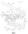
- FIG. 1is a perspective schematic view of a system for forming a tendon-bone graft according to the principles of the present disclosure
- FIG. 2is an exploded view of FIG. 1 according to the principles of the present disclosure
- FIG. 3is an exploded perspective view of the system for forming a tendon-bone graft according to the principles of the present disclosure
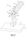
- FIG. 4is a perspective view of the system for forming a tendon-bone graft according to the principles of the present disclosure
- FIG. 5is a perspective view of a shaping member of the system for forming a tendon-bone graft according to the principles of the present disclosure
- FIG. 6is a partial front view of the system for forming a tendon-bone graft according to the principles of the present disclosure
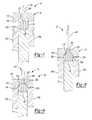
- FIG. 7is a simplified partial sectional view taken along line 4 - 4 of FIG. 4 illustrating a procedure for forming a tendon-bone graft using the system according to the principles of the present disclosure
- FIG. 8is a simplified partial sectional view taken along line 4 - 4 of FIG. 4 illustrating a procedure for forming a tendon-bone graft using the system according to the principles of the present disclosure
- FIG. 9is a simplified partial sectional view taken along line 4 - 4 of FIG. 4 illustrating a procedure for forming a tendon-bone graft using the system according to the principles of the present disclosure
- FIG. 10is a partial view of the system for forming a tendon-bone graft according to the principles of the present disclosure
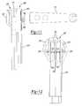
- FIG. 11is a side view of a guide of the system for forming a tendon-bone graft according to the principles of the present disclosure.
- FIG. 12is a front view of the guide of FIG. 11 according to the principles of the present disclosure.
- the graft forming system 10can include a base 12 , at least one support 14 , a first clamping system 16 , a second clamping system 18 , and a shaping member 20 .
- the system 10can be composed of any suitable sterilizable material, such as a metal or metal alloy including, but not limited to, stainless steel.
- the system 10can enable a user to form a tendon-bone graft 24 including at least one bone block 26 and a tendon 28 .
- a bone-tendon-bone graft or a bone blockcan also be formed.
- the system 10can be used to form the bone block 26 into a desired shape, such as a cylindrical or substantially cylindrical shape 26 b , prior to insertion of the tendon-bone graft into an anatomy.
- the base 12can include any suitable member or surface to which the support 14 and the second clamping system 18 can be coupled.
- Base 12can include a rectangular shape having a surface 32 and two threaded bores 34 positioned on a side face 36 of base 12 for optionally receiving stabilizing rods 38 .
- Support 14 and second clamping system 18can be operatively coupled to surface 32 of base 12 .
- the stabilizing rods 38can be used to provide increased stability of forming system 10 when base 12 is operated in a state where base 12 is not secured to another structure. By using stabilizing rods 38 for additional stability, base 12 can have a smaller footprint thereby being lighter and easier to transport.
- base 12is shown as having a rectangular shape and receiving stabilizing rods 38 , it should be appreciated that base 12 and/or stabilizing rods 38 can be optional, and the support 14 and second clamping system 18 can be operatively coupled to another structure such as an operating table or a tray in an operating room or other facility.
- the support 14can include a distal end 42 and a proximal end 44 and can be formed of any suitable sterilizable material, such as a metal or metal alloy.
- the distal end 42can be coupled to base 12 in any suitable manner, such as by fasteners, and the proximal end 44 can support the bone block 26 .
- the proximal end 44can include a bone holding surface 46 having a curved surface 48 to assist in retaining the bone block 26 during resection of bone block 26 by shaping member 20 , as will be discussed. While the bone holding surface 46 is shown as having the curved surface 48 , it should be appreciated that the bone holding surface 46 can have any appropriate contour, such as flat, convex, concave, etc. to assist in orientating and retaining bone block 26 during resection.
- the clamping system 16can include a first clamping plate 50 a and a second clamping plate 50 b arranged to selectively engage support 14 and bone block 26 to orient and hold bone block 26 centrally in place on bone holding surface 46 during resection.
- the first plate 50 acan be substantially identical to the second plate 50 b , and thus the same reference numerals will be used to refer to features of both the first plate 50 a and the second plate 50 b .
- Both the first and second plates 50 a , 50 bcan include a proximal end 52 , a distal end 54 , a support side 56 and an outer side 58 opposite the support side 56 .
- the first and second plates 50 a , 50 bcan each further include a pair of tabs or projections 60 disposed on support side 56 , and a channel 62 extending from a front side 64 to a rear side 66 on outer side 58 .
- first and second clamping plates 50 a , 50 bcan be positioned on support 14 such that the support side 56 can be contiguous to support 14 and projections 60 can be received in corresponding bores 68 that can be included in support 14 .
- a pair of fasteners or bolts 70can be received through an aperture 72 in the first and second plates 50 a , 50 b and threadably received in a corresponding bore 74 in support 14 to secure plates 50 a , 50 b to support 14 and retain bone block 26 as best shown in FIGS. 1 and 2 .
- a proximal portion of support side 56can contact bone block 26 to assist in holding bone block 26 in place during resection of bone block 26 .
- the plates 50 a , 50 bcan form a first clamping structure that provides a first clamping force in a first direction perpendicular to support 14 .
- Second clamping system 18can include a clamp support member 80 , a clamping blade 82 and a lever arm 84 .
- Clamp support member 80can include a body member 86 having a first member 88 at a distal end 90 and a second member 92 at a proximal end 94 , where each of the members can be integrally formed in a C-shaped structure as shown, for example, in FIGS. 1 and 2 . While clamp support member 80 has been shown as an integrally formed C-shaped structure, it should be appreciated that clamp support member 80 can be formed from various structures that may not be integrally formed, such as three separately formed portions assembled together.
- First member 88can serve as a base for clamp support member 80 and can include two longitudinally extending support members 96 spaced apart and arranged to be positioned adjacent to each side 98 of support 14 and on base surface 32 .
- Support 14can further include two longitudinally extending projections 100 protruding from sides 98 and arranged to engage a top surface 102 of support members 96 so as to retain clamp support member 80 in place during operation of second clamping system 18 , as will be discussed.
- Second member 92 of clamp support member 80can extend substantially perpendicular to body member 86 and over support 14 as shown, for example, in FIG. 1 .
- Second member 92can include a captured through slot 110 , a pair of longitudinally extending channels 112 and a biasing member 114 arranged to cooperate with slot 110 .
- Slot 110can be sized to slidably receive clamping blade 82 therethrough as shown, for example, in FIG. 1 .
- the inner dimensions of slot 110can be configured to substantially match corresponding outer dimensions of clamping blade 82 such that blade 82 can be received in sliding engagement with slot 110 with minimal clearance between blade 82 and slot 110 .
- Biasing member 114can include any suitable biasing member, such as a conventional spring loaded ball plunger assembly 114 arranged to cooperate with slot 110 and engage clamping blade 82 when positioned in slot 110 as shown in FIG. 2 .
- Ball plunger 114can be arranged to maintain a vertical position of clamping blade 82 relative to second member 92 when blade 82 is not being acted upon by lever arm 84 or engaged with bone block 26 , as will be discussed.
- the longitudinal extending channels 112can be positioned on each side 116 of second member 92 as shown, for example, in FIGS. 2 and 3 .
- Channels 112can include an open end 118 and a captured end 120 at an opposite end.
- the lever arm 84can include a handle portion 130 and a body portion 132 that can include two extending members 134 spaced apart a distance from each other as shown, for example, in FIGS. 2 and 3 .
- Lever arm 84can be made from any suitable sterilizable material such as metal or a metal alloy.
- Extending members 134can each include a pin 136 projecting from an inner face 138 of each extending member 134 .
- the lever arm 84can be engaged to second member 92 by sliding pins 136 into channel 112 through open end 118 until pins 136 are positioned at captured end 120 .
- Clamping blade 82can include a substantially rectangular shape having a proximal end 140 and a distal end 144 .
- the proximal end 140can include at least one bone engagement member 146 protruding from a bottom surface 148 .
- the bone engagement members 146can include any suitable mechanism for engaging the bone block 26 to hold the bone block in place during resection, such as at least one spike, tooth, cleat, etc.
- the distal end 144can extend beyond second member 92 when inserted through slot 110 and placed into contact with bone block 26 so as to enable a user to manipulate the clamping blade 82 by grasping the distal end 144 , as well as enable the lever arm 84 to engage the clamping blade 82 , as will be discussed. While clamping blade 82 is shown as having a rectangular shape, it should be appreciated that clamping blade 82 can be configured in other shapes suitable for insertion in slot 110 and engagement with bone block 26 .
- clamping blade 82With the bone block 26 positioned on bone support surface 46 and captured by clamping plates 50 a , 50 b as shown in FIG. 1 , clamping blade 82 can then be inserted through slot 110 and brought into a first engaged position contacting bone block 26 .
- Lever arm 84can then be brought into pivotal engagement with second member 92 as described above and pivoted about pins 136 so as to engage distal end 144 of clamping blade 82 .
- a second clamping force perpendicular to the first clamping forcecan then be imparted on clamping blade 82 by lever arm 84 to clamp bone block 26 to bone support surface 46 .
- the second clamping forcecan drive bone engagement members 146 into bone block 26 and clamping blade 82 to a second engaged position such that bottom surface 148 can contact bone block 26 .
- bone engagement members 146can be driven into bone block 26 to various points of engagement between the first and second engaged positions to clamp bone block 26 to support 14 .
- a pair of fasteners 150such as set screws, can be threaded through apertures 152 in second member 92 to secure clamping blade 82 in the second engaged position as shown, for example, in FIGS. 3 and 4 .
- Lever arm 84can then optionally be removed from second member 92 by sliding pins 136 along channel 112 to open end 118 while still retaining the second clamping force.
- Shaping member 20can be operable to resect the bone block 26 and can include a body portion 170 and a handle portion 172 .
- Body portion 170can include a proximal end 174 , a distal end 176 , a plurality of teeth 178 , and a longitudinally extending slot 180 .
- the plurality of teeth 178can extend from the proximal end 174 to the distal end 176 and can include an arcuate semi-circular shape separated by longitudinally extending slot 180 as shown, for example, in FIG. 5 .
- Teeth 178can have the same size from proximal end 174 to distal end 176 , and can shape or resect bone block 26 when moving shaping member 20 in a first direction and a second opposite direction relative to bone block 26 . Teeth 178 can extend outwardly from longitudinally extending slot 180 on bottom sliding surfaces 184 to permit the removal of any extraneous bone from bone block 26 . Longitudinally extending slot 180 can include an open end 182 at proximal end 174 for receiving clamping blade 82 into slot 180 as will be discussed. Body portion 170 can further include an aperture 186 through each sliding surface 184 and a handle support member 188 extending from distal end 176 .
- Handle portion 172can be made of any suitable sterilizable material such as plastic, metal or a metal alloy and can be affixed to handle support member 188 so as to abut distal end 176 as shown, for example, in FIG. 4 . While handle portion 172 has been shown as being separately formed and affixed to body portion 170 , it should be appreciated that handle portion can be integrally formed with body portion 170 .
- shaping member 20can be advanced over clamping blade 82 such that slot 180 can receive clamping blade 82 in sliding engagement.
- the extent to which a portion of the top surface 30 is resectedalso determines the amount of bone to be removed by shaping member 20 , and preferably is chosen based on the depth of penetration of bone engagement members 146 to minimize such resected amount.
- a guide 200can be provided to facilitate shaping and resecting of the top surface 30 of bone block 26 .
- guide 200can include two side members 202 having proximal ends 204 , distal ends 206 , and a support member 208 connecting side members 202 at their distal ends 206 to form a general U-shape configuration as shown in FIG. 3 .
- Side members 202can include a longitudinally extending rib 210 , and a channel 212 arranged to receive a wedge member 214 .
- Guide 200can be advanced over first and second plates 50 a , 50 b such that each rib 210 can engage the corresponding channel 62 in plates 50 a , 50 b to position guide 200 relative to bone block 26 as best shown in FIG. 6 .
- Guide 200can further include a top surface 216 and a threaded aperture 218 arranged to receive a fastener or bolt 220 .
- fastener 220can be inserted through aperture 218 and threadably received in threaded bore 222 of first plate 50 a to secure guide 200 in place.
- Wedge members 214can be inserted into channels 212 of guide 200 and each engage a side of bone block 26 to hold bone block 26 in place during any resection of top surface 30 .
- Wedge members 214can generate a parallel clamping force to the first clamping force generated by plates 50 a , 50 b on bone block 26 .
- a reciprocating bone saw or other suitable cutting devicecan be used for the resection.
- Clamping blade 82may need to be disengaged and raised from bone block 26 prior to resecting top surface 30 if bone engagement members 146 extend below top surface 216 of guide 200 .
- Clamping blade 82is re-engaged to bone block 26 and secured into the newly-resected top surface of bone block 26 .
- wedge members 214can be removed and then guide 200 can be removed from plates 50 a , 50 b after removing fastener 220 .
- Shaping member 20can then be advanced over clamping blade 82 such that slot 180 can receive clamping blade 82 in sliding engagement as generally shown in FIG. 4 .
- Shaping member 20can then be advanced in a first direction and a second opposite direction about clamping blade 82 in a direction perpendicular to the clamping force exerted by clamping blade 82 on bone block 26 .
- clamping blade 82can be engaged with bone block 26 to clamp bone block 26 to bone holding surface 46 , and the clamp force can be generated generally vertically, parallel to support 14 , and shaping member 20 can be advanced and retracted perpendicular to the clamp force, and thus, perpendicular to support 14 and clamping blade 82 .
- Clamping blade 82can also serve as a guide for advancing and retracting shaping member 20 to resect bone block 26 .
- Advancing shaping member 20 over bone block 26 as described abovecan resect the bone block 26 shown in FIG. 7 to a partially cylindrical shape 26 a ′ shown in FIG. 8 .
- a pressurecan be exerted on shaping member 20 in the direction of the clamping force exerted by clamping blade 82 to assist in resecting bone block 26 .
- Shaping member 20can be advanced and retracted to resect bone block 26 until sliding surface 184 of shaping member 20 contacts a top surface 230 of first and second plates 50 a , 50 b thereby forming a partially cylindrical surface 26 a ′ as shown in FIG. 8 .
- a protruding surface 26 a ′′can remain due to slot 180 in shaping member 20 as also shown in FIG. 8 .
- the protruding surface 26 a ′′can be resected to form the substantially cylindrical shape 26 b and to remove any indentations caused by engagement of the bone engagement members 146 with bone block 26 , as shown in FIG. 9 .
- shaping member 20can be secured to first and second plates 50 a , 50 b with fasteners 232 such that surfaces 184 of shaping member 20 engage top surfaces 230 of plates 50 a , 50 b .
- Fasteners 232can be inserted through apertures 186 in shaping member 20 and can be threadably received in corresponding bores 234 of clamping plates 50 a , 50 b as generally shown in FIG. 10 .
- protruding portion 26 a ′′can be resected with a cutting member 240 as shown in FIG. 9 .
- Cutting member 240can include a cutting surface 242 , and a depth guide 244 , and can include any suitable cutting member such as a carbide end mill.
- Cutting member 240can be coupled to any appropriate tool to facilitate moving or rotating cutting member 240 to resect protruding surface 26 a ′′.
- Cutting surface 242can be arranged to contact and resect protrusion 26 a ′′ until depth guide 244 contacts a top surface 246 of shaping member 20 to form the substantially cylindrical shape 26 b , as shown in FIG. 9 .
- shaping member 20 and cutting member 240may not necessarily be employed to resect protrusion 26 a ′′. Rather, any suitable cutting member could be employed such as a broach with centralized cutting teeth, a bone saw, etc. It should also be understood that bone block 26 can be formed into alternative shapes in additional to the substantially cylindrical shape 26 b , including but not limited to, substantially square or rectangular shapes, and the teeth 178 of shaping member 20 would conform to such alternative shapes.
- shaping member 20 and first and second plates 50 a , 50 bcan be removed to release bone block 26 from support 14 .
- system 10can be used to resect a second bone block 26 of a bone-tendon-bone graft.
- the prepared tendon-bone graft 24can be inserted into a prepared anatomy (not shown) and bone graft forming system 10 can be optionally disassembled for sterilization.
- Guide 250can be attached to the patella/patellar ligament/tibia portions 252 of donor tissue to recover the tendon-bone or bone-tendon-bone graft 24 that can be placed on support 14 as described above.
- Guide 250can include a body portion 254 that can be handled by a user and a fixture portion 256 that can receive and guide a saw blade or suitable cutting device.
- Fixture portion 256can be affixed to a ligament side of the donor tissue and secured in place with fasteners 258 .
- Fasteners 258can be any suitable fastener, such as a self tapping fastener, that can engage patella 260 to secure guide 250 to the patella.
- the fixture portioncan include at least three cutting slots 262 , 264 , 266 spaced apart by at least two visualization areas 268 .
- the cutting guidecan be affixed to the donor tissue such that the slots 262 - 266 are oriented parallel to a direction of ligament 270 .
- the cutting slots 262 - 266can receive a cutting blade 272 to cut the patella/ligament into two tendon-bone grafts 24 .
- cutting guide 250can have a varying number of cutting clots, such as two slots to form one graft or four slots to form three grafts, depending on, for example, the size of the donor patella.
- the cutting slotscan be positioned relative to each other such that a distance 274 between the slots corresponds to a predetermined dimension, such as a diameter, of the resected and formed bone block 26 with substantially cylindrical shape 26 b.
Landscapes
- Health & Medical Sciences (AREA)
- Transplantation (AREA)
- Orthopedic Medicine & Surgery (AREA)
- Heart & Thoracic Surgery (AREA)
- Cardiology (AREA)
- Oral & Maxillofacial Surgery (AREA)
- Engineering & Computer Science (AREA)
- Biomedical Technology (AREA)
- Physical Education & Sports Medicine (AREA)
- Vascular Medicine (AREA)
- Life Sciences & Earth Sciences (AREA)
- Animal Behavior & Ethology (AREA)
- General Health & Medical Sciences (AREA)
- Public Health (AREA)
- Veterinary Medicine (AREA)
- Surgical Instruments (AREA)
Abstract
Description
Claims (24)
Priority Applications (1)
| Application Number | Priority Date | Filing Date | Title |
|---|---|---|---|
| US12/436,361US8322256B2 (en) | 2007-10-05 | 2009-05-06 | System for forming a tendon-bone graft |
Applications Claiming Priority (2)
| Application Number | Priority Date | Filing Date | Title |
|---|---|---|---|
| US11/867,928US8303592B2 (en) | 2007-10-05 | 2007-10-05 | System for forming a tendon-bone graft |
| US12/436,361US8322256B2 (en) | 2007-10-05 | 2009-05-06 | System for forming a tendon-bone graft |
Related Parent Applications (1)
| Application Number | Title | Priority Date | Filing Date |
|---|---|---|---|
| US11/867,928Continuation-In-PartUS8303592B2 (en) | 2007-10-05 | 2007-10-05 | System for forming a tendon-bone graft |
Publications (2)
| Publication Number | Publication Date |
|---|---|
| US20090222052A1 US20090222052A1 (en) | 2009-09-03 |
| US8322256B2true US8322256B2 (en) | 2012-12-04 |
Family
ID=41013749
Family Applications (1)
| Application Number | Title | Priority Date | Filing Date |
|---|---|---|---|
| US12/436,361Expired - Fee RelatedUS8322256B2 (en) | 2007-10-05 | 2009-05-06 | System for forming a tendon-bone graft |
Country Status (1)
| Country | Link |
|---|---|
| US (1) | US8322256B2 (en) |
Cited By (1)
| Publication number | Priority date | Publication date | Assignee | Title |
|---|---|---|---|---|
| US11213406B2 (en)* | 2019-07-10 | 2022-01-04 | Arthrex, Inc. | Graft preparation station for repairing bone defects |
Families Citing this family (5)
| Publication number | Priority date | Publication date | Assignee | Title |
|---|---|---|---|---|
| US8303592B2 (en)* | 2007-10-05 | 2012-11-06 | Biomet Manufacturing Corp. | System for forming a tendon-bone graft |
| US9314330B2 (en) | 2010-01-15 | 2016-04-19 | Vivex Biomedical, Inc. | Fan folded fascia lata for cruciate ligament substitution and method and apparatus for making the same |
| CN104684507B (en)* | 2012-05-07 | 2017-04-19 | 史密夫和内修有限公司 | Compaction pliers having removable cutting inserts |
| CN102973310A (en)* | 2012-11-24 | 2013-03-20 | 宫大伟 | Implanted bone trimmer for traumatology department |
| DE102013221060B4 (en)* | 2013-10-17 | 2016-12-22 | Martin Geisinger | Bone chip processing station |
Citations (97)
| Publication number | Priority date | Publication date | Assignee | Title |
|---|---|---|---|---|
| US43909A (en) | 1864-08-23 | Hog-snout cutter | ||
| US493730A (en) | 1893-03-21 | Trephine | ||
| US1911873A (en) | 1931-07-21 | 1933-05-30 | Joseph Shapiro | Wafer cutting machine |
| US2573462A (en) | 1947-09-02 | 1951-10-30 | Lindsey Earle | Tubular rotary cutter |
| US2591516A (en) | 1950-05-08 | 1952-04-01 | Victor L Darnell | Dispensing device |
| US3835849A (en) | 1973-01-26 | 1974-09-17 | Guire G Mc | Bone clamp and adjustable drill guide |
| US3848601A (en) | 1972-06-14 | 1974-11-19 | G Ma | Method for interbody fusion of the spine |
| US4007732A (en) | 1975-09-02 | 1977-02-15 | Robert Carl Kvavle | Method for location and removal of soft tissue in human biopsy operations |
| US4010737A (en) | 1971-06-14 | 1977-03-08 | Vilaghy Miklos I | Bone biopsy instrument kit |
| US4059115A (en) | 1976-06-14 | 1977-11-22 | Georgy Stepanovich Jumashev | Surgical instrument for operation of anterior fenestrated spondylodessis in vertebral osteochondrosis |
| US4177797A (en) | 1977-03-04 | 1979-12-11 | Shelby M. Baylis | Rotary biopsy device and method of using same |
| US4416278A (en) | 1979-07-26 | 1983-11-22 | Miller Joseph E | Bone plug cutter |
| US4565192A (en) | 1984-04-12 | 1986-01-21 | Shapiro James A | Device for cutting a patella and method therefor |
| US4627853A (en) | 1985-05-29 | 1986-12-09 | American Hospital Supply Corporation | Method of producing prostheses for replacement of articular cartilage and prostheses so produced |
| US4649918A (en) | 1980-09-03 | 1987-03-17 | Custom Medical Devices, Inc. | Bone core removing tool |
| US4741651A (en) | 1986-04-25 | 1988-05-03 | Despres Roger J | Hole saw |
| US4782833A (en) | 1987-02-19 | 1988-11-08 | Thomas A. Einhorn | Bone boring instrument |
| US4904259A (en) | 1988-04-29 | 1990-02-27 | Samuel Itay | Compositions and methods for repair of cartilage and bone |
| US4913143A (en) | 1986-05-28 | 1990-04-03 | The United States Of America As Represented By The Secretary Of The Air Force | Trephine assembly |
| US4936313A (en) | 1987-11-18 | 1990-06-26 | Institut Strauman AG | Power tool for excising a bone or cartilage biopsy |
| US5041117A (en) | 1989-08-31 | 1991-08-20 | Boehringer Mannheim Corporation | Elbow arthroplasty instrumentation and surgical procedure |
| US5053050A (en) | 1988-04-29 | 1991-10-01 | Samuel Itay | Compositions for repair of cartilage and bone |
| US5139520A (en) | 1990-01-31 | 1992-08-18 | American Cyanamid Company | Method for acl reconstruction |
| US5152763A (en) | 1991-04-02 | 1992-10-06 | Johnson Lanny L | Method for grafting bone |
| US5197967A (en) | 1991-04-02 | 1993-03-30 | Synthes (U.S.A.) | Trephine instrument and method for cutting annular holes |
| US5211647A (en) | 1992-02-19 | 1993-05-18 | Arthrex Inc. | Interference screw and cannulated sheath for endosteal fixation of ligaments |
| US5269786A (en) | 1992-02-20 | 1993-12-14 | Arthrex Inc. | PCL oriented placement tibial guide method |
| US5320626A (en) | 1992-02-19 | 1994-06-14 | Arthrex Inc. | Endoscopic drill guide |
| US5320115A (en) | 1991-01-16 | 1994-06-14 | Applied Biological Concepts | Method and apparatus for arthroscopic knee surgery |
| US5341816A (en) | 1989-11-06 | 1994-08-30 | Allen William C | Biopsy device |
| US5397357A (en) | 1993-02-18 | 1995-03-14 | Arthrex, Inc. | Method for preparing a bone-tendon-bone core graft |
| US5415651A (en) | 1993-02-18 | 1995-05-16 | Arthrex, Inc. | Work station for preparing a bone-tendon-bone core graft |
| US5423823A (en) | 1993-02-18 | 1995-06-13 | Arthrex Inc. | Coring reamer |
| US5496326A (en) | 1991-06-27 | 1996-03-05 | Johnson; Lanny L. | Fixation screw and method for ligament reconstruction |
| DE19503504A1 (en) | 1994-09-16 | 1996-03-21 | Metrimed Orvosi Mueszergyarto | Instrument set for osteochondral transplant |
| US5513662A (en) | 1991-12-31 | 1996-05-07 | Osteotech, Inc. | Preparation of bone for transplantation |
| US5540692A (en)* | 1994-07-13 | 1996-07-30 | Midas Rex Pneumatic Tools, Inc. | Replicator for resecting bone to match a pattern |
| US5562669A (en) | 1994-01-13 | 1996-10-08 | Mcguire; David A. | Cruciate ligament reconstruction with tibial drill guide |
| US5603716A (en) | 1995-02-16 | 1997-02-18 | Arthrex Inc. | Method of ligament reconstruction using double socket graft placement and fixation |
| US5655546A (en) | 1995-06-07 | 1997-08-12 | Halpern; Alan A. | Method for cartilage repair |
| US5733289A (en) | 1992-10-27 | 1998-03-31 | Neoligaments Limited | Ligament graft harvesting |
| US5782835A (en) | 1995-03-07 | 1998-07-21 | Innovasive Devices, Inc. | Apparatus and methods for articular cartilage defect repair |
| US5817098A (en) | 1995-05-17 | 1998-10-06 | Astra Aktiebolag | Drill guide instrument |
| US5827288A (en) | 1997-04-10 | 1998-10-27 | Midas Rex, L.P. | Circular hole forming apparatus |
| US5865834A (en) | 1991-12-13 | 1999-02-02 | Mcguire; David A. | Coring reamer |
| US5885293A (en) | 1997-03-03 | 1999-03-23 | Innovasive Devices, Inc. | Apparatus and method for cutting a surface at a repeatable angle |
| US5895390A (en) | 1996-09-19 | 1999-04-20 | Biomet, Inc. | Pin placement guide used in making a bone entry hole for implantation of an intramedullary nail |
| US5904717A (en) | 1986-01-28 | 1999-05-18 | Thm Biomedical, Inc. | Method and device for reconstruction of articular cartilage |
| US5918604A (en) | 1997-02-12 | 1999-07-06 | Arthrex, Inc. | Method of loading tendons into the knee |
| US5919196A (en) | 1995-02-16 | 1999-07-06 | Arthrex, Inc. | Method and apparatus for osteochondral autograft transplantation |
| US6007496A (en) | 1996-12-30 | 1999-12-28 | Brannon; James K. | Syringe assembly for harvesting bone |
| US6110178A (en) | 1997-04-25 | 2000-08-29 | Sulzer Orthopadie Ag | Apparatus for the production of endochondral or osteochondral bores |
| US6146385A (en) | 1997-02-11 | 2000-11-14 | Smith & Nephew, Inc. | Repairing cartilage |
| US6179839B1 (en) | 1999-09-20 | 2001-01-30 | Kinetikos Medical Incorporated | Bone fusion apparatus and method |
| US6187329B1 (en) | 1997-12-23 | 2001-02-13 | Board Of Regents Of The University Of Texas System | Variable permeability bone implants, methods for their preparation and use |
| US6231577B1 (en)* | 1999-08-12 | 2001-05-15 | James T. Canedy | Device for creating cylindrical bone plugs for patella-patellar tendon-tibia grafts |
| US6242247B1 (en) | 1996-06-04 | 2001-06-05 | Sulzer Orthopedics Ltd. | Method for making cartilage and implants |
| US6280447B1 (en) | 1998-12-23 | 2001-08-28 | Nuvasive, Inc. | Bony tissue resector |
| US20010027322A1 (en) | 1999-07-23 | 2001-10-04 | Bowman Steven M. | Instrument for inserting graft fixation device |
| US20010039455A1 (en) | 2000-03-14 | 2001-11-08 | Timothy Simon | Cartilage repair plug |
| US20020022847A1 (en) | 1998-04-09 | 2002-02-21 | Ray Eddie F. | Methods and instrumentation for vertebral interbody fusion |
| US6375658B1 (en) | 2000-04-28 | 2002-04-23 | Smith & Nephew, Inc. | Cartilage grafting |
| US6395011B1 (en) | 1998-07-17 | 2002-05-28 | Johnson & Johnson | Method and apparatus for harvesting and implanting bone plugs |
| US20020082704A1 (en) | 2000-05-15 | 2002-06-27 | Cryolife, Inc. | Osteochondral transplant techniques |
| US20020095214A1 (en) | 2001-01-16 | 2002-07-18 | Hyde Edward R. | Transosseous core approach and instrumentation for joint replacement and repair |
| US6442814B1 (en)* | 1999-04-23 | 2002-09-03 | Spinal Concepts, Inc. | Apparatus for manufacturing a bone dowel |
| US6458144B1 (en)* | 1999-12-30 | 2002-10-01 | Osteotech, Inc. | Methods for manufacturing skeletal implants |
| US20030009218A1 (en) | 1997-07-23 | 2003-01-09 | Boucher James A. | Apparatus and method for tibial fixation of soft tissue |
| US6528052B1 (en) | 2000-09-29 | 2003-03-04 | The Board Of Trustees Of The Leland Stanford Junior University | Method for in vivo ex vivo and in vitro repair and regeneration of cartilage and collagen and bone remodeling |
| US6530928B1 (en) | 1999-03-23 | 2003-03-11 | Sulzer Orthopedics Ltd. | Instrument, instrument set and a method for the introduction of an osteochondral transplant |
| US6557226B1 (en)* | 1999-04-23 | 2003-05-06 | Michael E. Landry | Apparatus for manufacturing a bone dowel |
| US20030130662A1 (en) | 1998-06-09 | 2003-07-10 | Michelson Gary K. | Device and method for preparing a space between adjacent vertebrae to receive an insert |
| US6591581B2 (en) | 2000-03-08 | 2003-07-15 | Arthrex, Inc. | Method for preparing and inserting round, size specific osteochondral cores in the knee |
| US6592588B1 (en) | 1995-02-16 | 2003-07-15 | Arthrex, Inc. | Apparatus for osteochondral autograft transplantation |
| US6607534B2 (en) | 1990-06-28 | 2003-08-19 | Peter M. Bonutti | Tissue engagement method |
| US6613054B2 (en) | 1998-08-14 | 2003-09-02 | Kyphon Inc. | Systems and methods for placing materials into bone |
| US20030212435A1 (en) | 2002-03-26 | 2003-11-13 | Adam Gold | Handleless clamping device |
| US6685709B2 (en) | 1996-06-04 | 2004-02-03 | Joseph H. Sklar | Apparatus and method for reconstructing ligaments |
| US6696073B2 (en) | 1999-02-23 | 2004-02-24 | Osteotech, Inc. | Shaped load-bearing osteoimplant and methods of making same |
| US6727224B1 (en) | 1999-02-01 | 2004-04-27 | Genetics Institute, Llc. | Methods and compositions for healing and repair of articular cartilage |
| US6740484B1 (en) | 1999-04-13 | 2004-05-25 | Organ Recovery Systems, Inc. | Method of cryopreservation of tissues by vitrification |
| US20040106928A1 (en) | 2002-12-03 | 2004-06-03 | Steven Ek | Tibial resurfacing system |
| US20040162622A1 (en) | 2000-03-14 | 2004-08-19 | Chondosite, Llc | Cartilage repair plug |
| US6796977B2 (en) | 2001-09-28 | 2004-09-28 | Depuy Mitek, Inc. | Variable graft tensioner |
| US20040210227A1 (en) | 2003-02-03 | 2004-10-21 | Kinetikos Medical, Inc. | Compression screw apparatuses, systems and methods |
| US20040230303A1 (en) | 2003-05-16 | 2004-11-18 | Gomes Katherine A. | Cartilage allograft plug |
| US6835377B2 (en) | 1998-05-13 | 2004-12-28 | Osiris Therapeutics, Inc. | Osteoarthritis cartilage regeneration |
| US20050064042A1 (en) | 2003-04-29 | 2005-03-24 | Musculoskeletal Transplant Foundation | Cartilage implant plug with fibrin glue and method for implantation |
| US20050222576A1 (en) | 2004-03-18 | 2005-10-06 | Kick George F | Expandable medical access device |
| US6962592B2 (en)* | 2002-09-11 | 2005-11-08 | Cortek, Inc. | Allograft implant cutting machine |
| US20060142775A1 (en) | 2004-12-29 | 2006-06-29 | Depuy Mitek, Inc. | Surgical tool with cannulated rotary tip |
| US20070093896A1 (en) | 2005-10-26 | 2007-04-26 | Malinin Theodore I | Method and instrumentation for the preparation and transplantation of osteochondral allografts |
| US7231815B2 (en) | 2004-12-02 | 2007-06-19 | Construction Technology Laboratories, Inc. | Relative humidity probe for concrete |
| US7241316B2 (en) | 2002-06-13 | 2007-07-10 | Douglas G Evans | Devices and methods for treating defects in the tissue of a living being |
| US20070276506A1 (en) | 2006-05-25 | 2007-11-29 | Biomet Manufacturing Corp. | Demineralized osteochondral plug |
| US7347130B2 (en)* | 2003-12-16 | 2008-03-25 | Stryker Spine | Apparatus and method for cutting spinal implants |
| US20090093853A1 (en) | 2007-10-05 | 2009-04-09 | Biomet Manufacturing Corp. | System For Forming A Tendon-Bone Graft |
Family Cites Families (1)
| Publication number | Priority date | Publication date | Assignee | Title |
|---|---|---|---|---|
| US5728161A (en)* | 1995-06-08 | 1998-03-17 | Depuy Orthopedics, Inc. | Large taper modular shoulder prosthesis |
- 2009
- 2009-05-06USUS12/436,361patent/US8322256B2/ennot_activeExpired - Fee Related
Patent Citations (108)
| Publication number | Priority date | Publication date | Assignee | Title |
|---|---|---|---|---|
| US43909A (en) | 1864-08-23 | Hog-snout cutter | ||
| US493730A (en) | 1893-03-21 | Trephine | ||
| US1911873A (en) | 1931-07-21 | 1933-05-30 | Joseph Shapiro | Wafer cutting machine |
| US2573462A (en) | 1947-09-02 | 1951-10-30 | Lindsey Earle | Tubular rotary cutter |
| US2591516A (en) | 1950-05-08 | 1952-04-01 | Victor L Darnell | Dispensing device |
| US4010737A (en) | 1971-06-14 | 1977-03-08 | Vilaghy Miklos I | Bone biopsy instrument kit |
| US3848601A (en) | 1972-06-14 | 1974-11-19 | G Ma | Method for interbody fusion of the spine |
| US3835849A (en) | 1973-01-26 | 1974-09-17 | Guire G Mc | Bone clamp and adjustable drill guide |
| US4007732A (en) | 1975-09-02 | 1977-02-15 | Robert Carl Kvavle | Method for location and removal of soft tissue in human biopsy operations |
| US4059115A (en) | 1976-06-14 | 1977-11-22 | Georgy Stepanovich Jumashev | Surgical instrument for operation of anterior fenestrated spondylodessis in vertebral osteochondrosis |
| US4177797A (en) | 1977-03-04 | 1979-12-11 | Shelby M. Baylis | Rotary biopsy device and method of using same |
| US4416278A (en) | 1979-07-26 | 1983-11-22 | Miller Joseph E | Bone plug cutter |
| US4649918A (en) | 1980-09-03 | 1987-03-17 | Custom Medical Devices, Inc. | Bone core removing tool |
| US4565192A (en) | 1984-04-12 | 1986-01-21 | Shapiro James A | Device for cutting a patella and method therefor |
| US4627853A (en) | 1985-05-29 | 1986-12-09 | American Hospital Supply Corporation | Method of producing prostheses for replacement of articular cartilage and prostheses so produced |
| US5904717A (en) | 1986-01-28 | 1999-05-18 | Thm Biomedical, Inc. | Method and device for reconstruction of articular cartilage |
| US4741651A (en) | 1986-04-25 | 1988-05-03 | Despres Roger J | Hole saw |
| US4913143A (en) | 1986-05-28 | 1990-04-03 | The United States Of America As Represented By The Secretary Of The Air Force | Trephine assembly |
| US4782833A (en) | 1987-02-19 | 1988-11-08 | Thomas A. Einhorn | Bone boring instrument |
| US4936313A (en) | 1987-11-18 | 1990-06-26 | Institut Strauman AG | Power tool for excising a bone or cartilage biopsy |
| US5053050A (en) | 1988-04-29 | 1991-10-01 | Samuel Itay | Compositions for repair of cartilage and bone |
| US4904259A (en) | 1988-04-29 | 1990-02-27 | Samuel Itay | Compositions and methods for repair of cartilage and bone |
| US5041117A (en) | 1989-08-31 | 1991-08-20 | Boehringer Mannheim Corporation | Elbow arthroplasty instrumentation and surgical procedure |
| US5341816A (en) | 1989-11-06 | 1994-08-30 | Allen William C | Biopsy device |
| US5139520A (en) | 1990-01-31 | 1992-08-18 | American Cyanamid Company | Method for acl reconstruction |
| US6607534B2 (en) | 1990-06-28 | 2003-08-19 | Peter M. Bonutti | Tissue engagement method |
| US5320115A (en) | 1991-01-16 | 1994-06-14 | Applied Biological Concepts | Method and apparatus for arthroscopic knee surgery |
| US5197967A (en) | 1991-04-02 | 1993-03-30 | Synthes (U.S.A.) | Trephine instrument and method for cutting annular holes |
| US5152763A (en) | 1991-04-02 | 1992-10-06 | Johnson Lanny L | Method for grafting bone |
| US5496326A (en) | 1991-06-27 | 1996-03-05 | Johnson; Lanny L. | Fixation screw and method for ligament reconstruction |
| US5865834A (en) | 1991-12-13 | 1999-02-02 | Mcguire; David A. | Coring reamer |
| US5513662A (en) | 1991-12-31 | 1996-05-07 | Osteotech, Inc. | Preparation of bone for transplantation |
| US5320626A (en) | 1992-02-19 | 1994-06-14 | Arthrex Inc. | Endoscopic drill guide |
| US5211647A (en) | 1992-02-19 | 1993-05-18 | Arthrex Inc. | Interference screw and cannulated sheath for endosteal fixation of ligaments |
| US5269786A (en) | 1992-02-20 | 1993-12-14 | Arthrex Inc. | PCL oriented placement tibial guide method |
| US5733289A (en) | 1992-10-27 | 1998-03-31 | Neoligaments Limited | Ligament graft harvesting |
| US5397357A (en) | 1993-02-18 | 1995-03-14 | Arthrex, Inc. | Method for preparing a bone-tendon-bone core graft |
| US5423823A (en) | 1993-02-18 | 1995-06-13 | Arthrex Inc. | Coring reamer |
| US5415651A (en) | 1993-02-18 | 1995-05-16 | Arthrex, Inc. | Work station for preparing a bone-tendon-bone core graft |
| US5562669A (en) | 1994-01-13 | 1996-10-08 | Mcguire; David A. | Cruciate ligament reconstruction with tibial drill guide |
| US5540692A (en)* | 1994-07-13 | 1996-07-30 | Midas Rex Pneumatic Tools, Inc. | Replicator for resecting bone to match a pattern |
| DE19503504A1 (en) | 1994-09-16 | 1996-03-21 | Metrimed Orvosi Mueszergyarto | Instrument set for osteochondral transplant |
| US5603716A (en) | 1995-02-16 | 1997-02-18 | Arthrex Inc. | Method of ligament reconstruction using double socket graft placement and fixation |
| US5919196A (en) | 1995-02-16 | 1999-07-06 | Arthrex, Inc. | Method and apparatus for osteochondral autograft transplantation |
| US5785714A (en) | 1995-02-16 | 1998-07-28 | Arthrex, Inc. | Method of ACL reconstruction using double socket graft placement and fixation |
| US6592588B1 (en) | 1995-02-16 | 2003-07-15 | Arthrex, Inc. | Apparatus for osteochondral autograft transplantation |
| US5782835A (en) | 1995-03-07 | 1998-07-21 | Innovasive Devices, Inc. | Apparatus and methods for articular cartilage defect repair |
| US6017348A (en) | 1995-03-07 | 2000-01-25 | Innovasive Devices, Inc. | Apparatus and methods for articular cartilage defect repair |
| US5817098A (en) | 1995-05-17 | 1998-10-06 | Astra Aktiebolag | Drill guide instrument |
| US6179871B1 (en) | 1995-06-07 | 2001-01-30 | Alan A. Halpern | Means for cartilage repair |
| US5655546A (en) | 1995-06-07 | 1997-08-12 | Halpern; Alan A. | Method for cartilage repair |
| US6685709B2 (en) | 1996-06-04 | 2004-02-03 | Joseph H. Sklar | Apparatus and method for reconstructing ligaments |
| US6242247B1 (en) | 1996-06-04 | 2001-06-05 | Sulzer Orthopedics Ltd. | Method for making cartilage and implants |
| US6387693B2 (en) | 1996-06-04 | 2002-05-14 | Sulzer Orthopedics Ltd. | Method for producing cartilage tissue and implants for repairing enchondral and osteochondral defects as well as arrangement for carrying out the method |
| US5895390A (en) | 1996-09-19 | 1999-04-20 | Biomet, Inc. | Pin placement guide used in making a bone entry hole for implantation of an intramedullary nail |
| US6007496A (en) | 1996-12-30 | 1999-12-28 | Brannon; James K. | Syringe assembly for harvesting bone |
| US6146385A (en) | 1997-02-11 | 2000-11-14 | Smith & Nephew, Inc. | Repairing cartilage |
| US6358253B1 (en) | 1997-02-11 | 2002-03-19 | Smith & Newhew Inc | Repairing cartilage |
| US5918604A (en) | 1997-02-12 | 1999-07-06 | Arthrex, Inc. | Method of loading tendons into the knee |
| US5885293A (en) | 1997-03-03 | 1999-03-23 | Innovasive Devices, Inc. | Apparatus and method for cutting a surface at a repeatable angle |
| US5827288A (en) | 1997-04-10 | 1998-10-27 | Midas Rex, L.P. | Circular hole forming apparatus |
| US6110178A (en) | 1997-04-25 | 2000-08-29 | Sulzer Orthopadie Ag | Apparatus for the production of endochondral or osteochondral bores |
| US20030009218A1 (en) | 1997-07-23 | 2003-01-09 | Boucher James A. | Apparatus and method for tibial fixation of soft tissue |
| US6187329B1 (en) | 1997-12-23 | 2001-02-13 | Board Of Regents Of The University Of Texas System | Variable permeability bone implants, methods for their preparation and use |
| US20020022847A1 (en) | 1998-04-09 | 2002-02-21 | Ray Eddie F. | Methods and instrumentation for vertebral interbody fusion |
| US6835377B2 (en) | 1998-05-13 | 2004-12-28 | Osiris Therapeutics, Inc. | Osteoarthritis cartilage regeneration |
| US20030130662A1 (en) | 1998-06-09 | 2003-07-10 | Michelson Gary K. | Device and method for preparing a space between adjacent vertebrae to receive an insert |
| US6395011B1 (en) | 1998-07-17 | 2002-05-28 | Johnson & Johnson | Method and apparatus for harvesting and implanting bone plugs |
| US6613054B2 (en) | 1998-08-14 | 2003-09-02 | Kyphon Inc. | Systems and methods for placing materials into bone |
| US6280447B1 (en) | 1998-12-23 | 2001-08-28 | Nuvasive, Inc. | Bony tissue resector |
| US6727224B1 (en) | 1999-02-01 | 2004-04-27 | Genetics Institute, Llc. | Methods and compositions for healing and repair of articular cartilage |
| US6696073B2 (en) | 1999-02-23 | 2004-02-24 | Osteotech, Inc. | Shaped load-bearing osteoimplant and methods of making same |
| US6530928B1 (en) | 1999-03-23 | 2003-03-11 | Sulzer Orthopedics Ltd. | Instrument, instrument set and a method for the introduction of an osteochondral transplant |
| US6740484B1 (en) | 1999-04-13 | 2004-05-25 | Organ Recovery Systems, Inc. | Method of cryopreservation of tissues by vitrification |
| US6557226B1 (en)* | 1999-04-23 | 2003-05-06 | Michael E. Landry | Apparatus for manufacturing a bone dowel |
| US6442814B1 (en)* | 1999-04-23 | 2002-09-03 | Spinal Concepts, Inc. | Apparatus for manufacturing a bone dowel |
| US20010027322A1 (en) | 1999-07-23 | 2001-10-04 | Bowman Steven M. | Instrument for inserting graft fixation device |
| US6231577B1 (en)* | 1999-08-12 | 2001-05-15 | James T. Canedy | Device for creating cylindrical bone plugs for patella-patellar tendon-tibia grafts |
| US6179839B1 (en) | 1999-09-20 | 2001-01-30 | Kinetikos Medical Incorporated | Bone fusion apparatus and method |
| US6458144B1 (en)* | 1999-12-30 | 2002-10-01 | Osteotech, Inc. | Methods for manufacturing skeletal implants |
| US6591581B2 (en) | 2000-03-08 | 2003-07-15 | Arthrex, Inc. | Method for preparing and inserting round, size specific osteochondral cores in the knee |
| US20010039455A1 (en) | 2000-03-14 | 2001-11-08 | Timothy Simon | Cartilage repair plug |
| US20040162622A1 (en) | 2000-03-14 | 2004-08-19 | Chondosite, Llc | Cartilage repair plug |
| US6375658B1 (en) | 2000-04-28 | 2002-04-23 | Smith & Nephew, Inc. | Cartilage grafting |
| US6852114B2 (en) | 2000-05-15 | 2005-02-08 | Cryolife, Inc. | Osteochondral transplant techniques |
| US20020082704A1 (en) | 2000-05-15 | 2002-06-27 | Cryolife, Inc. | Osteochondral transplant techniques |
| US6488033B1 (en) | 2000-05-15 | 2002-12-03 | Cryolife, Inc. | Osteochondral transplant techniques |
| US6528052B1 (en) | 2000-09-29 | 2003-03-04 | The Board Of Trustees Of The Leland Stanford Junior University | Method for in vivo ex vivo and in vitro repair and regeneration of cartilage and collagen and bone remodeling |
| US20020095214A1 (en) | 2001-01-16 | 2002-07-18 | Hyde Edward R. | Transosseous core approach and instrumentation for joint replacement and repair |
| US6796977B2 (en) | 2001-09-28 | 2004-09-28 | Depuy Mitek, Inc. | Variable graft tensioner |
| US20030212435A1 (en) | 2002-03-26 | 2003-11-13 | Adam Gold | Handleless clamping device |
| US7241316B2 (en) | 2002-06-13 | 2007-07-10 | Douglas G Evans | Devices and methods for treating defects in the tissue of a living being |
| US6962592B2 (en)* | 2002-09-11 | 2005-11-08 | Cortek, Inc. | Allograft implant cutting machine |
| US20040106928A1 (en) | 2002-12-03 | 2004-06-03 | Steven Ek | Tibial resurfacing system |
| US20040210227A1 (en) | 2003-02-03 | 2004-10-21 | Kinetikos Medical, Inc. | Compression screw apparatuses, systems and methods |
| US20050064042A1 (en) | 2003-04-29 | 2005-03-24 | Musculoskeletal Transplant Foundation | Cartilage implant plug with fibrin glue and method for implantation |
| WO2004103224A1 (en) | 2003-05-16 | 2004-12-02 | Musculoskeletal Transplant Foundation | Cartilage allograft plug |
| US20040230303A1 (en) | 2003-05-16 | 2004-11-18 | Gomes Katherine A. | Cartilage allograft plug |
| US7347130B2 (en)* | 2003-12-16 | 2008-03-25 | Stryker Spine | Apparatus and method for cutting spinal implants |
| US20050222576A1 (en) | 2004-03-18 | 2005-10-06 | Kick George F | Expandable medical access device |
| US7231815B2 (en) | 2004-12-02 | 2007-06-19 | Construction Technology Laboratories, Inc. | Relative humidity probe for concrete |
| US20060142775A1 (en) | 2004-12-29 | 2006-06-29 | Depuy Mitek, Inc. | Surgical tool with cannulated rotary tip |
| US20070135918A1 (en) | 2005-10-26 | 2007-06-14 | Malinin Theodore I | Instrumentation for the preparation and transplantation of osteochondral allografts |
| US20070135917A1 (en) | 2005-10-26 | 2007-06-14 | Malinin Theodore I | Instrumentation for the preparation and transplantation of osteochondral allografts |
| US20070135928A1 (en) | 2005-10-26 | 2007-06-14 | Malinin Theodore I | Osteochondral allografts |
| US20070093896A1 (en) | 2005-10-26 | 2007-04-26 | Malinin Theodore I | Method and instrumentation for the preparation and transplantation of osteochondral allografts |
| US20070276506A1 (en) | 2006-05-25 | 2007-11-29 | Biomet Manufacturing Corp. | Demineralized osteochondral plug |
| US20090093853A1 (en) | 2007-10-05 | 2009-04-09 | Biomet Manufacturing Corp. | System For Forming A Tendon-Bone Graft |
Non-Patent Citations (30)
| Title |
|---|
| "Matrices for Cartilage Repair," Coutes, et al., published in Clinical Orthopaedics & Related Research, No. 391S pp. S271-S279, copyright 2001 Lippincott Williams & Wilkins, Inc. |
| "Techniques for ACL Reconstruction with Multi-Trac(TM) Drill Guide," available by 2000. |
| "Techniques for ACL Reconstruction with Multi-Trac™ Drill Guide," available by 2000. |
| Acufex Microsurgical, Inc., "Endoscopic Technique for ACL Reconstruction with Pro-Trac Tibial Guide: Endobutton Fixation," available by 2000. |
| Arthrex, "Osteochondral Autograft Transfer System (OATS), Key Words: Chondral defects, osteochondral cylinder transplants, arthroscopic technique, chronic ACL deficiency" © Arthrex Inc.,1996 (1 page). |
| Arthrex, Osteochondral Autograft Transfer System (OATS)(TM), "Surgical Technique," 1996 (pp. 1-24). |
| Arthrex, Osteochondral Autograft Transfer System (OATS), "Surgical Technique," [undated] (pp. 1-21). |
| Arthrex, Osteochondral Autograft Transfer System (OATS)™, "Surgical Technique," 1996 (pp. 1-24). |
| Arthrotek® OCD System, Osteochondral Defect Surgical Technique, brochure, © 1999 (4 pages). |
| Christel, P., et al., "Osteochondral Grafting Using Mosaicplasty Technique," www.maitrise-orthop.com/corpusmaitri/orthopaedic/mo76-mosaicplasty/index.shtml (23 pages). |
| Chu et al., Articular Cartilage Transplantation-Clinical Results in the Knee, clinical Orthopaedics and Related Research, No. 360, pp. 159-168 Lippincott, Williams 8 Wilkins, (Mar. 1999). |
| Convery et al., "Long-Term Survival of Chondrocytes in an Osteochondral Articular Cartilage Allograft," Journal of Bone and Joint Surgery, vol. 78-A, No. 7, pp. 1082-1088 (Jul. 1996). |
| Gross, M.D., Allan, "Cartilage Resurfacing Filling Defects," The Journal of Arthroplasty vol. 18 No. 3 Suppl. 1 (2003) pp. 14-17. |
| Hangody et al., Autologous Osteochondral Mosaicplasty for the Treatment of Full-Thickness Defects of Weight-Bearing Joints, Journal of Bone and Joint Surgery, vol. 85-a, Supp. 2, pp. 25-32 (2003). |
| Hangody, et al., "Arthroscopic autogenous osteochondral mosaicplasty for the treatment of femoral condylar articular defects, A preliminary report," Knee, Surg, Sports Traumatol, Arthrosc (1997) © Springer-Verlag 1997 5:262-267. |
| Hangody, M.D., et al., "MosaicPlasty(TM) Osteochondral Grafting Technique Guide", Smith & Nephew Endoscopy, © 1996. |
| Hangody, M.D., et al., "MosaicPlasty™ Osteochondral Grafting Technique Guide", Smith & Nephew Endoscopy, © 1996. |
| Innovasive Cor(TM) System, © 1997 Innovasive Devices, Inc. (2 pages). |
| Innovasive Cor™ System, © 1997 Innovasive Devices, Inc. (2 pages). |
| Instrument Makar, Inc., "Bone Grafters Surgical Technique," Dec. 1995. |
| Instrument Makar, Inc.,"New Directions in Arthroscopic Innovation," 1991 Catalogue. |
| Jakob, M.D., Roland, et al., "Autologous Osteochondral grafting in the Knee: Indication, Results, and Reflections," Clinical Orthopaedics and Related Research No. 401, (2002) pp. 170-184. |
| Levitt, M.D., et al., Articular Cartilage Resurfacing with Fresh Pre-Cut Osteochondral Core Allografts, Power Point Presentation, University of Miami, Department of Orthopaedics and Rehabilitation [undated]. |
| Malinin et al., "Articular Cartilage Nutrition is Mediated by Subchondral Bone: a Long-Term Autograft Study in Baboons," Osteoarthritis and Cartilage, vol. 8, pp. 483-491, OsteoArthritis Research Society Intl. (2000). |
| Malinin et al., Hypothermic Storage and Cryopreservation of Cartilage, Clinical Orthopedics and Related Research, No. 197, pp. 1526 (Jul.-Aug. 1985). |
| Malinin, T., M.D., Human Cadaver Femoral Head Homografts for Anterior Cervical Spine Fusions, Reprinted from Surgical Neurology, vol. 7, No. 4, apr. 1977, Copyright, © 1977. |
| Malinin, T.I., "University of Miami Tissue Bank: Collection of Postmortem Tissues for Clinical Use and Laboratory Investigation", From the Departments of Surgery and Pathology, University of Miami School of Medicine and the Veterans Administration Hospital, Transplantation Proceedings, vol. VIII, No. 2, Supplement 1 (June), 1976 (pp. 53-58). |
| Matsusue, Y., et al., "Arthroplasty using Mosaicplasty,", NCBI Pub Med, www.ncbi.nlm.nih.gov/entrez/query.fcgi?CMD=Display&DB=pubmed [printed May 29, 2007]. |
| Szerb, M.D., et al., "Mosaicplasty, Long-Term Follow-Up," Bulletin of the Hospital for Joint Diseases, vol. 63, Nos. 1 & 2 (2005), pp. 54-62. |
| Williams et al.. "Prolonged Storage Effects on the Articular Cartilage of Fresh Human Osteochondral Allografts," Journal of Bone and Joint Surgery, vol. 85-A, No. 1 1, pp. 21 11-21 20 (Nov. 2003). |
Cited By (3)
| Publication number | Priority date | Publication date | Assignee | Title |
|---|---|---|---|---|
| US11213406B2 (en)* | 2019-07-10 | 2022-01-04 | Arthrex, Inc. | Graft preparation station for repairing bone defects |
| US20220117758A1 (en)* | 2019-07-10 | 2022-04-21 | Arthrex, Inc. | Graft preparation station for repairing bone defects |
| US11801150B2 (en)* | 2019-07-10 | 2023-10-31 | Arthrex, Inc. | Graft preparation station for repairing bone defects |
Also Published As
| Publication number | Publication date |
|---|---|
| US20090222052A1 (en) | 2009-09-03 |
Similar Documents
| Publication | Publication Date | Title |
|---|---|---|
| US10709457B2 (en) | High tibial osteotomy guide | |
| US10206730B2 (en) | Instrumentation and technique for sizing a bone reconstruction graft | |
| US7867280B2 (en) | Methods for mounting and using tethered joint bearing implants | |
| JP4309397B2 (en) | Method and apparatus for knee resection with low invasiveness | |
| US6056754A (en) | Method and apparatus for patella resection and guide handle | |
| US9421022B2 (en) | Method and apparatus for total knee arthroplasty | |
| US8322256B2 (en) | System for forming a tendon-bone graft | |
| US8795284B2 (en) | Instrumentation for repair of meniscus tissue | |
| AU635009B2 (en) | Apparatus and method for knee surgery | |
| US20120053591A1 (en) | Apparatuses for femoral and tibial resection | |
| US20070043265A1 (en) | Patellar retractor and method of surgical procedure on knee | |
| US20160120651A1 (en) | Total Knee Arthroplasty System and Method | |
| GB2398015A (en) | Bone die cutter | |
| JP2008528110A (en) | Pulley groove implant and related methods and instruments | |
| US8092488B2 (en) | Bone retractor tool | |
| US7879040B2 (en) | Method and apparatus for osteochondral autograft transplantation | |
| US8303592B2 (en) | System for forming a tendon-bone graft |
Legal Events
| Date | Code | Title | Description |
|---|---|---|---|
| AS | Assignment | Owner name:BIOMET MANUFACTURING CORP., INDIANA Free format text:ASSIGNMENT OF ASSIGNORS INTEREST;ASSIGNOR:VANDEWALLE, MARK V.;REEL/FRAME:022647/0706 Effective date:20090506 | |
| AS | Assignment | Owner name:BANK OF AMERICA, N.A., AS ADMINISTRATIVE AGENT FOR Free format text:SECURITY AGREEMENT;ASSIGNORS:LVB ACQUISITION, INC.;BIOMET, INC.;BIOMET 3I, LLC;AND OTHERS;REEL/FRAME:023505/0241 Effective date:20091111 | |
| ZAAA | Notice of allowance and fees due | Free format text:ORIGINAL CODE: NOA | |
| ZAAB | Notice of allowance mailed | Free format text:ORIGINAL CODE: MN/=. | |
| STCF | Information on status: patent grant | Free format text:PATENTED CASE | |
| AS | Assignment | Owner name:BIOMET MANUFACTURING, LLC, INDIANA Free format text:CHANGE OF NAME;ASSIGNOR:BIOMET MANUFACTURING CORPORATION;REEL/FRAME:030656/0702 Effective date:20130603 | |
| AS | Assignment | Owner name:BIOMET TRAVEL, INC., INDIANA Free format text:RELEASE OF SECURITY INTEREST IN PATENTS RECORDED AT REEL 023505/ FRAME 0241;ASSIGNOR:BANK OF AMERICA, N.A., AS ADMINISTRATIVE AGENT;REEL/FRAME:037155/0082 Effective date:20150624 Owner name:BIOLECTRON, INC., INDIANA Free format text:RELEASE OF SECURITY INTEREST IN PATENTS RECORDED AT REEL 023505/ FRAME 0241;ASSIGNOR:BANK OF AMERICA, N.A., AS ADMINISTRATIVE AGENT;REEL/FRAME:037155/0082 Effective date:20150624 Owner name:IMPLANT INNOVATIONS HOLDINGS, LLC, INDIANA Free format text:RELEASE OF SECURITY INTEREST IN PATENTS RECORDED AT REEL 023505/ FRAME 0241;ASSIGNOR:BANK OF AMERICA, N.A., AS ADMINISTRATIVE AGENT;REEL/FRAME:037155/0082 Effective date:20150624 Owner name:LVB ACQUISITION, INC., INDIANA Free format text:RELEASE OF SECURITY INTEREST IN PATENTS RECORDED AT REEL 023505/ FRAME 0241;ASSIGNOR:BANK OF AMERICA, N.A., AS ADMINISTRATIVE AGENT;REEL/FRAME:037155/0082 Effective date:20150624 Owner name:EBI MEDICAL SYSTEMS, LLC, INDIANA Free format text:RELEASE OF SECURITY INTEREST IN PATENTS RECORDED AT REEL 023505/ FRAME 0241;ASSIGNOR:BANK OF AMERICA, N.A., AS ADMINISTRATIVE AGENT;REEL/FRAME:037155/0082 Effective date:20150624 Owner name:BIOMET BIOLOGICS, LLC., INDIANA Free format text:RELEASE OF SECURITY INTEREST IN PATENTS RECORDED AT REEL 023505/ FRAME 0241;ASSIGNOR:BANK OF AMERICA, N.A., AS ADMINISTRATIVE AGENT;REEL/FRAME:037155/0082 Effective date:20150624 Owner name:BIOMET FLORIDA SERVICES, LLC, INDIANA Free format text:RELEASE OF SECURITY INTEREST IN PATENTS RECORDED AT REEL 023505/ FRAME 0241;ASSIGNOR:BANK OF AMERICA, N.A., AS ADMINISTRATIVE AGENT;REEL/FRAME:037155/0082 Effective date:20150624 Owner name:BIOMET EUROPE LTD., INDIANA Free format text:RELEASE OF SECURITY INTEREST IN PATENTS RECORDED AT REEL 023505/ FRAME 0241;ASSIGNOR:BANK OF AMERICA, N.A., AS ADMINISTRATIVE AGENT;REEL/FRAME:037155/0082 Effective date:20150624 Owner name:BIOMET LEASING, INC., INDIANA Free format text:RELEASE OF SECURITY INTEREST IN PATENTS RECORDED AT REEL 023505/ FRAME 0241;ASSIGNOR:BANK OF AMERICA, N.A., AS ADMINISTRATIVE AGENT;REEL/FRAME:037155/0082 Effective date:20150624 Owner name:BIOMET HOLDINGS LTD., INDIANA Free format text:RELEASE OF SECURITY INTEREST IN PATENTS RECORDED AT REEL 023505/ FRAME 0241;ASSIGNOR:BANK OF AMERICA, N.A., AS ADMINISTRATIVE AGENT;REEL/FRAME:037155/0082 Effective date:20150624 Owner name:ELECTR-OBIOLOGY, LLC, INDIANA Free format text:RELEASE OF SECURITY INTEREST IN PATENTS RECORDED AT REEL 023505/ FRAME 0241;ASSIGNOR:BANK OF AMERICA, N.A., AS ADMINISTRATIVE AGENT;REEL/FRAME:037155/0082 Effective date:20150624 Owner name:BIOMET MANUFACTURING CORPORATION, INDIANA Free format text:RELEASE OF SECURITY INTEREST IN PATENTS RECORDED AT REEL 023505/ FRAME 0241;ASSIGNOR:BANK OF AMERICA, N.A., AS ADMINISTRATIVE AGENT;REEL/FRAME:037155/0082 Effective date:20150624 Owner name:INTERPORE CROSS INTERNATIONAL, LLC, CALIFORNIA Free format text:RELEASE OF SECURITY INTEREST IN PATENTS RECORDED AT REEL 023505/ FRAME 0241;ASSIGNOR:BANK OF AMERICA, N.A., AS ADMINISTRATIVE AGENT;REEL/FRAME:037155/0082 Effective date:20150624 Owner name:BIOMET, INC., INDIANA Free format text:RELEASE OF SECURITY INTEREST IN PATENTS RECORDED AT REEL 023505/ FRAME 0241;ASSIGNOR:BANK OF AMERICA, N.A., AS ADMINISTRATIVE AGENT;REEL/FRAME:037155/0082 Effective date:20150624 Owner name:CROSS MEDICAL PRODUCTS, LLC, CALIFORNIA Free format text:RELEASE OF SECURITY INTEREST IN PATENTS RECORDED AT REEL 023505/ FRAME 0241;ASSIGNOR:BANK OF AMERICA, N.A., AS ADMINISTRATIVE AGENT;REEL/FRAME:037155/0082 Effective date:20150624 Owner name:INTERPORE SPINE, LTD., CALIFORNIA Free format text:RELEASE OF SECURITY INTEREST IN PATENTS RECORDED AT REEL 023505/ FRAME 0241;ASSIGNOR:BANK OF AMERICA, N.A., AS ADMINISTRATIVE AGENT;REEL/FRAME:037155/0082 Effective date:20150624 Owner name:BIOMET FAIR LAWN LLC, NEW JERSEY Free format text:RELEASE OF SECURITY INTEREST IN PATENTS RECORDED AT REEL 023505/ FRAME 0241;ASSIGNOR:BANK OF AMERICA, N.A., AS ADMINISTRATIVE AGENT;REEL/FRAME:037155/0082 Effective date:20150624 Owner name:EBI, LLC, INDIANA Free format text:RELEASE OF SECURITY INTEREST IN PATENTS RECORDED AT REEL 023505/ FRAME 0241;ASSIGNOR:BANK OF AMERICA, N.A., AS ADMINISTRATIVE AGENT;REEL/FRAME:037155/0082 Effective date:20150624 Owner name:KIRSCHNER MEDICAL CORPORATION, INDIANA Free format text:RELEASE OF SECURITY INTEREST IN PATENTS RECORDED AT REEL 023505/ FRAME 0241;ASSIGNOR:BANK OF AMERICA, N.A., AS ADMINISTRATIVE AGENT;REEL/FRAME:037155/0082 Effective date:20150624 Owner name:BIOMET 3I, LLC, FLORIDA Free format text:RELEASE OF SECURITY INTEREST IN PATENTS RECORDED AT REEL 023505/ FRAME 0241;ASSIGNOR:BANK OF AMERICA, N.A., AS ADMINISTRATIVE AGENT;REEL/FRAME:037155/0082 Effective date:20150624 Owner name:EBI HOLDINGS, LLC, INDIANA Free format text:RELEASE OF SECURITY INTEREST IN PATENTS RECORDED AT REEL 023505/ FRAME 0241;ASSIGNOR:BANK OF AMERICA, N.A., AS ADMINISTRATIVE AGENT;REEL/FRAME:037155/0082 Effective date:20150624 Owner name:BIOMET INTERNATIONAL LTD., INDIANA Free format text:RELEASE OF SECURITY INTEREST IN PATENTS RECORDED AT REEL 023505/ FRAME 0241;ASSIGNOR:BANK OF AMERICA, N.A., AS ADMINISTRATIVE AGENT;REEL/FRAME:037155/0082 Effective date:20150624 Owner name:BIOMET SPORTS MEDICINE, LLC, INDIANA Free format text:RELEASE OF SECURITY INTEREST IN PATENTS RECORDED AT REEL 023505/ FRAME 0241;ASSIGNOR:BANK OF AMERICA, N.A., AS ADMINISTRATIVE AGENT;REEL/FRAME:037155/0082 Effective date:20150624 Owner name:BIOMET ORTHOPEDICS, LLC, INDIANA Free format text:RELEASE OF SECURITY INTEREST IN PATENTS RECORDED AT REEL 023505/ FRAME 0241;ASSIGNOR:BANK OF AMERICA, N.A., AS ADMINISTRATIVE AGENT;REEL/FRAME:037155/0082 Effective date:20150624 Owner name:BIOMET MICROFIXATION, LLC, FLORIDA Free format text:RELEASE OF SECURITY INTEREST IN PATENTS RECORDED AT REEL 023505/ FRAME 0241;ASSIGNOR:BANK OF AMERICA, N.A., AS ADMINISTRATIVE AGENT;REEL/FRAME:037155/0082 Effective date:20150624 | |
| FPAY | Fee payment | Year of fee payment:4 | |
| MAFP | Maintenance fee payment | Free format text:PAYMENT OF MAINTENANCE FEE, 8TH YEAR, LARGE ENTITY (ORIGINAL EVENT CODE: M1552); ENTITY STATUS OF PATENT OWNER: LARGE ENTITY Year of fee payment:8 | |
| FEPP | Fee payment procedure | Free format text:MAINTENANCE FEE REMINDER MAILED (ORIGINAL EVENT CODE: REM.); ENTITY STATUS OF PATENT OWNER: LARGE ENTITY | |
| LAPS | Lapse for failure to pay maintenance fees | Free format text:PATENT EXPIRED FOR FAILURE TO PAY MAINTENANCE FEES (ORIGINAL EVENT CODE: EXP.); ENTITY STATUS OF PATENT OWNER: LARGE ENTITY | |
| STCH | Information on status: patent discontinuation | Free format text:PATENT EXPIRED DUE TO NONPAYMENT OF MAINTENANCE FEES UNDER 37 CFR 1.362 | |
| FP | Lapsed due to failure to pay maintenance fee | Effective date:20241204 |