US8322197B2 - Method and apparatus for injecting a liquid sample in an HPLC analyzing device, and valve assembly for use therein - Google Patents
Method and apparatus for injecting a liquid sample in an HPLC analyzing device, and valve assembly for use thereinDownload PDFInfo
- Publication number
- US8322197B2 US8322197B2US12/588,840US58884009AUS8322197B2US 8322197 B2US8322197 B2US 8322197B2US 58884009 AUS58884009 AUS 58884009AUS 8322197 B2US8322197 B2US 8322197B2
- Authority
- US
- United States
- Prior art keywords
- valve
- circuit
- outlet
- sample
- assembly
- Prior art date
- Legal status (The legal status is an assumption and is not a legal conclusion. Google has not performed a legal analysis and makes no representation as to the accuracy of the status listed.)
- Active, expires
Links
- 239000007788liquidSubstances0.000titleclaimsabstractdescription37
- 238000004128high performance liquid chromatographyMethods0.000titleclaimsabstractdescription28
- 238000000034methodMethods0.000titleclaimsabstractdescription18
- 238000004891communicationMethods0.000claimsdescription7
- 239000012530fluidSubstances0.000claimsdescription6
- 239000002699waste materialSubstances0.000claimsdescription5
- 230000000712assemblyEffects0.000description2
- 238000000429assemblyMethods0.000description2
- 230000006837decompressionEffects0.000description2
- 230000002349favourable effectEffects0.000description2
- 238000004519manufacturing processMethods0.000description2
- 238000012986modificationMethods0.000description2
- 230000004048modificationEffects0.000description2
- 230000009286beneficial effectEffects0.000description1
- 238000011109contaminationMethods0.000description1
- 238000012864cross contaminationMethods0.000description1
- 230000001419dependent effectEffects0.000description1
- 238000013461designMethods0.000description1
- 230000007613environmental effectEffects0.000description1
- 238000003780insertionMethods0.000description1
- 230000037431insertionEffects0.000description1
- 238000004811liquid chromatographyMethods0.000description1
- 238000005406washingMethods0.000description1
Images


Classifications
- G—PHYSICS
- G01—MEASURING; TESTING
- G01N—INVESTIGATING OR ANALYSING MATERIALS BY DETERMINING THEIR CHEMICAL OR PHYSICAL PROPERTIES
- G01N30/00—Investigating or analysing materials by separation into components using adsorption, absorption or similar phenomena or using ion-exchange, e.g. chromatography or field flow fractionation
- G01N30/02—Column chromatography
- G01N30/04—Preparation or injection of sample to be analysed
- G01N30/16—Injection
- G01N30/20—Injection using a sampling valve
- G—PHYSICS
- G01—MEASURING; TESTING
- G01N—INVESTIGATING OR ANALYSING MATERIALS BY DETERMINING THEIR CHEMICAL OR PHYSICAL PROPERTIES
- G01N30/00—Investigating or analysing materials by separation into components using adsorption, absorption or similar phenomena or using ion-exchange, e.g. chromatography or field flow fractionation
- G01N30/02—Column chromatography
- G01N30/04—Preparation or injection of sample to be analysed
- G01N30/16—Injection
- G01N30/22—Injection in high pressure liquid systems
- G—PHYSICS
- G01—MEASURING; TESTING
- G01N—INVESTIGATING OR ANALYSING MATERIALS BY DETERMINING THEIR CHEMICAL OR PHYSICAL PROPERTIES
- G01N35/00—Automatic analysis not limited to methods or materials provided for in any single one of groups G01N1/00 - G01N33/00; Handling materials therefor
- G01N35/10—Devices for transferring samples or any liquids to, in, or from, the analysis apparatus, e.g. suction devices, injection devices
- G01N35/1095—Devices for transferring samples or any liquids to, in, or from, the analysis apparatus, e.g. suction devices, injection devices for supplying the samples to flow-through analysers
- G01N35/1097—Devices for transferring samples or any liquids to, in, or from, the analysis apparatus, e.g. suction devices, injection devices for supplying the samples to flow-through analysers characterised by the valves
Definitions
- the inventionrelates to a method for injecting a liquid sample in an HPLC analyzing device.
- the inventionalso relates to an apparatus for injecting a liquid sample in an HPLC analyzing device.
- the inventionfurthermore relates to a valve assembly for use in such a method and in such an apparatus.
- HPLCHigh Pressure Liquid Chromatography
- UHPLCUltra High Pressure Liquid Chromatography
- the valve assemblyUpon completion of the said step of initializing the apparatus, the valve assembly is in the second valve position, which means that the sample loop is part of the second liquid circuit then.
- the second circuitincluding the sample loop thereof, is containing the mobile phase then.
- the initial quantity of the samplehas been supplied to the first liquid circuit for example by means of aspirating the sample via a needle out of a sample holder. Often, the sample holder has different compartments containing different samples.
- the first circuittypically is also connected to a washing liquid container and to a waste container.
- the liquid pressure in the first circuitis relatively low, usually equalling environmental pressure, thus giving rise to a pressure difference with the pressure of the mobile phase in the second circuit, from which second circuit there has to be injected, at a later stage, liquid with high pressure into the analyzing device.
- the valve assemblyAfter completion of said initializing step, the valve assembly is switched from the second valve position into the first valve position. During this switching of the valve assembly, the sample loop is losing its role as being a part of the second circuit and is attaining a role as being part of the first circuit.
- an additional quantity of the sampleis supplied into the first circuit to such an extent that the sample loop is at least partly filled with the sample. This may for example be achieved by means of aspirating, via the needle, additional sample out of the sample holder.
- the sample in the sample loopis contained in the second circuit, so that the sample together with the mobile phase can be injected from the second circuit into the analyzing device.
- This uncontrolled outflowis undesirable for at least the following reasons. At first, it may lead to contamination and/or cross-contamination of a sample holder. Furthermore, due to the uncontrolled outflow, the quantity of the sample between the sample supply means and the first valve inlet is not accurately known anymore. This results in problems with dosing the sample, especially in cases where the sample loop has to be only partially filled with the sample by the said supplying of the said additional quantity of the sample into the first circuit.
- the inventionprovides a method for injecting a liquid sample in an HPLC analyzing device.
- the intermediate valve positionis automatically and temporarily attained when switching from the second valve position into the first valve position, while in that temporary intermediate valve position the cut-off high pressure mobile phase in the sample loop will expand by successively flowing through one of the first and second valve terminals, the fourth chamber and the third valve outlet.
- the third valve outletmay for example be in communication with the outside environment via a free ending hose connected to the third valve outlet.
- the valve assemblyis of the stator/rotor type and comprises a first valve element and a second valve element.
- the first valve elementmay be the stator part of the valve assembly, while the second valve element is the rotor part of the valve assembly.
- the first valve elementis the rotor part of the valve assembly, while the second valve element is the stator part of the valve assembly.
- valve assemblymay comprise one or more additional inlets, outlets, terminals, connection chambers, etcetera, in its first and/or second valve elements, in addition to the mentioned first and second inlets, first, second and third outlets, first and second valve terminals, first, second, third and fourth connection chambers.
- each of the mentioned valve inlets, valve outlets and valve terminalsmay have various shapes and may be situated at various locations of the first valve element.
- each of the mentioned connection chambersmay have various shapes and may be situated at various locations of the second valve element.
- the connection chambersmay be channels, such as the circularly-arched channels known in the art for the first, second and third connection chambers.
- otherwise-arched channelssuch as spirally-arched channels, or straight channels may also be applied, and even nonchannel forms are possible for the connection chambers.
- the third valve outlet and the fourth connection chamberare arranged such that at least during the relative rotative movement about the rotation axis of the two valve elements from the second valve position into the intermediate valve position the fourth chamber continuously is in fluid communication with the third valve outlet.
- Such arrangements of the third valve outlet and of the fourth connection chamberstimulate a quick decompression of the sample loop in the temporary intermediate valve position.
- the third valve outletis arranged such that the rotation axis is enclosed by a cross section of the third valve outlet, as seen in a plane transverse to the rotation axis. This is for example the case when the rotation axis forms the center of said cross section.
- the third valve outletis centrally situated within the valve assembly.
- Such central arrangement of the third valve outletfits the general design requirements of HPLC valve assemblies very well and is favourable in view of compactness of the valve assembly, since the central area of the valve assembly normally is neither occupied by the first and second valve inlets, valve outlets and valve terminals, nor by the first, second and third connection chambers.
- the inventionprovides an apparatus for injecting a liquid sample in an HPLC analyzing device, as well as an HPLC valve assembly of the stator/rotor.
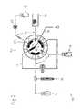
- FIG. 1shows a phase of an example of an embodiment of a method according to the invention, wherein the valve assembly is in its second valve position.
- FIG. 2shows another phase of said method embodiment, wherein the valve assembly is in its intermediate valve position.
- FIG. 3shows a yet other phase of said method embodiment, wherein the valve assembly is in its first valve position.
- HPLC analysing devicefor example a HPLC column
- apparatus for injecting a liquid sample into the analysing device 43is denoted by reference numeral 50 .
- the apparatus 50comprises a first liquid circuit 11 , a second liquid circuit 12 , a valve assembly 30 of the stator/rotor type, and a sample loop 14 .
- the first circuit 11 and the second circuit 12are connected with one another via the valve assembly 30 , which comprises a first valve element and a second valve element 32 co-operating with one another and rotatable relative to one another about a rotation axis 33 for switching between different valve positions of the valve assembly.
- the first valve elementis the stator of the valve assembly 30
- the second valve element 32is the rotor of the valve assembly 30 .
- Both ends of the sample loop 14are connected to the valve assembly 30 such that in a first valve position and in a second valve position of the valve assembly, respectively, the sample loop is either part of the first circuit 11 or part of the second circuit 12 , respectively.
- the switching of the valve assembly from the second valve position (shown in FIG. 1 ) into the first valve position (shown in FIG. 3 )is done by rotating the rotor 32 relative to the stator around the rotation axis 33 in the direction of the arrow 37 , which arrow is shown in FIG. 1 .
- the switching of the valve assembly from the first valve position (shown in FIG. 3 ) into the second valve position (shown in FIG. 1 )is done by rotating the rotor 32 relative to the stator around the rotation axis 33 in the direction of the arrow 38 , which arrow is shown in FIG. 3 .
- the statorcomprises a first valve inlet 1 connected in the first circuit to sample supply means 40 , a first valve outlet 2 connected in the first circuit to waste discharge means 41 , a second valve inlet 4 connected in the second circuit to mobile phase supply means 42 , a second valve outlet 5 connected in the second circuit to the analyzing device 43 , a first valve terminal 3 connected to one end of the sample loop 14 , and a second valve terminal 6 connected to the other end of the sample loop 14 .
- FIGS. 1-3show a cylinder-piston assembly 44 included in the first liquid circuit 11 .
- This assembly 44is merely meant as a symbolic illustration of means for displacing liquid in the first liquid circuit 11 .
- the rotor 32comprises a first connection chamber 21 , a second connection chamber 22 and a third connection chamber 23 .
- these connection chambersare circularly-arched channels, as known in the art, the center of the circular archs being formed by the rotation axis 33 .
- the first channel 21connects the second valve inlet 4 with the second valve outlet 5
- the second channel 22connects the second terminal 6 with the first valve inlet 1
- the third channel 23connects the first valve outlet 2 with the first valve terminal 3 .
- the sample loop 14is part of the first circuit 11 , not of the second circuit 12 .
- the HPLC pump 35when in the first valve position of FIG. 3 the HPLC pump 35 is in operation, the pump 35 will not be active on liquid contained in the sample loop 14 .
- the first channel 21connects the first valve terminal 3 with the second valve inlet 4
- the second channel 22connects the second valve outlet 5 with the second valve terminal 6
- the third channel 23connects the first valve inlet 1 with the first valve outlet 2 .
- the sample loop 14is part of the second circuit 12 , not of the first circuit 11 .
- the HPLC pump 35when in the second valve position of FIG. 1 the HPLC pump 35 is in operation, the pump 35 will indeed be active on liquid contained in the sample loop 14 .
- statorcomprises a third valve outlet 7 and the rotor 32 comprises a fourth connection chamber 24 such that during switching of the valve assembly 30 from the second valve position (shown in FIG. 1 ) into the first valve position (shown in FIG. 3 ) the valve assembly temporarily assumes the intermediate valve position (shown in FIG. 2 ) inbetween the second valve position and the first valve position.
- the fourth chamber 24connects the first valve terminal 3 with the third valve outlet 7 , while in that intermediate valve position the sample loop 14 is neither part of the first circuit 11 nor part of the second circuit 12 .
- the third valve outlet 7is in communication with the outside environment via a hose 34 connected to the third valve outlet 7 .
- the third valve outlet 7 and the fourth connection chamber 24are arranged such that at least during the relative rotative movement about the rotation axis 33 of the two valve elements from the second valve position into the intermediate valve position the fourth chamber 24 continuously is in fluid communication with the third valve outlet 7 .
- the third valve outlet 7is arranged such that, as seen in a plane transverse to the rotation axis 33 , the rotation axis 33 is enclosed by a cross section of the third valve outlet 7 . More specifically, the rotation axis 33 forms the center of said cross section.
- the fourth connection chamber 24may have various shapes and may be situated at various locations of the rotor 32 . In the shown example, the fourth connection chamber 24 has the shape of a channel whose longitudinal direction extends radially relative to the rotation axis 33 .
- initializing steps of a method according to the inventioncan be performed using the apparatus 50 with its HPLC valve assembly 30 .
- an initial quantity of the sampleis supplied at least into a section of the first circuit 11 between the sample supply means 40 and the first valve inlet 1 , and mobile phase is supplied into the second circuit 12 which includes the sample loop 14 .
- the liquid pressure in the second circuit 12is higher than the liquid pressure in the first circuit 11 .
- the valve assembly 30is switched from the second valve position (shown in FIG. 1 ) into the first valve position (shown in FIG. 3 ).
- the valve assembly 30temporarily assumes the intermediate valve position (shown in FIG. 2 ).
- the high pressure mobile phase in the sample loop 14will expand and decompress by successively flowing through the first valve terminal 3 , the fourth channel 24 and the third valve outlet 7 .
- Via the hose 34some of the mobile phase may be discarded, which is symbolically indicated by means of a depicted droplet in FIG. 2 .
- said decompressed mobile phaseis being inserted into the first circuit 11 , it will not expand anymore in the first circuit 11 .
- an additional quantity of the sampleis supplied into the first circuit to such an extent that the sample loop 14 is at least partly filled with the sample.
- valve assembly 30is switched from the first valve position (shown in FIG. 3 ) into the second valve position (shown in FIG. 1 ) by rotating the rotor 32 relative to the stator in the direction of arrow 38 , which arrow is indicated in FIG. 3 .
- the sample in the sample loopis contained in the second circuit 12 then.
- the sample together with the mobile phaseis injected from the second circuit 12 into the analysing device 43 .
- first connection chamber 21such that during the switching of the valve assembly from the second into the first valve position, it connects the second valve inlet 4 with the second valve outlet 5 at an earlier moment than shown in the Figures, for example already at the moment when the intermediate valve position of FIG. 2 is attained.
- Thiscan for example be realized by designing the circularly-arched connection channel 21 , as seen in FIG. 1 , with a somewhat extended length from its right hand side in FIG. 1 in the direction of the arrow 37 .
- Such an enlarged first connection chambermay be useful when applying an HPLC pump 35 which, during switching of the valve assembly, is continuously in operation.
Landscapes
- Physics & Mathematics (AREA)
- Health & Medical Sciences (AREA)
- Life Sciences & Earth Sciences (AREA)
- Chemical & Material Sciences (AREA)
- Analytical Chemistry (AREA)
- Biochemistry (AREA)
- General Health & Medical Sciences (AREA)
- General Physics & Mathematics (AREA)
- Immunology (AREA)
- Pathology (AREA)
- Fluid Mechanics (AREA)
- Sampling And Sample Adjustment (AREA)
- Automatic Analysis And Handling Materials Therefor (AREA)
Abstract
Description
Claims (9)
Applications Claiming Priority (3)
| Application Number | Priority Date | Filing Date | Title |
|---|---|---|---|
| EP08171387.7AEP2196801B1 (en) | 2008-12-11 | 2008-12-11 | Method and apparatus for injecting a liquid sample in an HPLC analyzing device, and valve assembly for use therein. |
| EP08171387 | 2008-12-11 | ||
| EP08171387.7 | 2008-12-11 |
Publications (2)
| Publication Number | Publication Date |
|---|---|
| US20100147086A1 US20100147086A1 (en) | 2010-06-17 |
| US8322197B2true US8322197B2 (en) | 2012-12-04 |
Family
ID=40578555
Family Applications (1)
| Application Number | Title | Priority Date | Filing Date |
|---|---|---|---|
| US12/588,840Active2031-03-12US8322197B2 (en) | 2008-12-11 | 2009-10-29 | Method and apparatus for injecting a liquid sample in an HPLC analyzing device, and valve assembly for use therein |
Country Status (2)
| Country | Link |
|---|---|
| US (1) | US8322197B2 (en) |
| EP (1) | EP2196801B1 (en) |
Cited By (9)
| Publication number | Priority date | Publication date | Assignee | Title |
|---|---|---|---|---|
| US8944102B1 (en)* | 2011-03-07 | 2015-02-03 | Elemental Scientific, Inc. | Gas burst injection valve |
| US20160061788A1 (en)* | 2013-04-22 | 2016-03-03 | Sekisui Medical Co., Ltd. | Switching valve for flow type analysis apparatus |
| US20160274074A1 (en)* | 2015-03-19 | 2016-09-22 | Shimadzu Corporation | Refractive index detector and liquid chromatograph |
| US9541207B1 (en)* | 2014-02-03 | 2017-01-10 | Elemental Scientific, Inc. | Valve assembly with bottom bypass ports |
| US9752691B1 (en)* | 2014-07-03 | 2017-09-05 | Elemental Scientific, Inc. | Valve for controlled shuttle of liquid into microtiter plates and mixing |
| US11204306B2 (en)* | 2018-08-10 | 2021-12-21 | Elemental Scientific, Inc. | Preconcentration of fluid samples with alternating dual loop introduction |
| US11441978B1 (en)* | 2018-04-12 | 2022-09-13 | Elemental Scientific, Inc. | Automatic evaporative sample preparation |
| US11773999B2 (en)* | 2017-01-27 | 2023-10-03 | Agilent Technologies, Inc. | Fluid valve having a coating containing gold and/or platinum |
| US11835496B2 (en) | 2019-12-23 | 2023-12-05 | Waters Technologies Corporation | Sample metering and injection for liquid chromatography |
Families Citing this family (8)
| Publication number | Priority date | Publication date | Assignee | Title |
|---|---|---|---|---|
| DE102008006266B4 (en) | 2008-01-25 | 2011-06-09 | Dionex Softron Gmbh | Sampler for liquid chromatography, in particular for high performance liquid chromatography |
| AU2009347432B2 (en) | 2009-06-03 | 2015-01-29 | Agilent Technologies, Inc. | Sample injector with metering device balancing pressure differences in an intermediate valve state |
| CN102808971B (en)* | 2012-01-09 | 2014-09-03 | 加拿大博朗科技有限公司 | Fluid selector valve |
| CN103134889B (en)* | 2013-01-25 | 2015-03-04 | 中山大学 | On-line enrichment-substep focus sample introduction-ultra-high performance liquid chromatography combination system and application |
| DE202016100451U1 (en) | 2015-06-25 | 2016-02-16 | Dionex Softron Gmbh | Sampler for liquid chromatography, in particular for high performance liquid chromatography |
| EP3650850B1 (en)* | 2017-07-04 | 2025-03-26 | Shimadzu Corporation | Autosampler and fluid chromatograph |
| JP6647380B1 (en)* | 2018-12-26 | 2020-02-14 | 日本分光株式会社 | Sample injection device |
| CN114184723B (en)* | 2021-12-30 | 2025-02-18 | 泰渡生物科技(苏州)有限公司 | Rotary valve, sample loading device and chromatography experiment system |
Citations (29)
| Publication number | Priority date | Publication date | Assignee | Title |
|---|---|---|---|---|
| US2571000A (en)* | 1948-05-01 | 1951-10-09 | Mckays Company | Water softening system and apparatus |
| US2979079A (en)* | 1957-12-30 | 1961-04-11 | Turak Anthony | Plural dispensing valve |
| US3080887A (en)* | 1961-03-06 | 1963-03-12 | Modernair Corp | Fluid pressure-operated multi-way valve |
| US3514210A (en)* | 1968-01-15 | 1970-05-26 | Jiri Hrdina | Device for programmed drawing off of gas bubbles from a measuring cell separator and the liquid from the extinction cell space |
| US3975946A (en) | 1974-02-27 | 1976-08-24 | Micromeritics Instrument Corporation | Liquid chromatography sample measuring and introducing apparatus |
| US4059009A (en)* | 1976-09-10 | 1977-11-22 | Micromeritics Instrument Corporation | Liquid chromatography system |
| US4243071A (en) | 1978-08-23 | 1981-01-06 | Altex Scientific, Inc. | Sample injection valve |
| US4444066A (en) | 1981-06-29 | 1984-04-24 | Beckman Instruments, Inc. | High pressure sample injector valve |
| US4506558A (en) | 1983-03-03 | 1985-03-26 | Rheodyne Incorporated | Injector with minimal flow-interrupt transient |
| US4625569A (en)* | 1984-01-17 | 1986-12-02 | Toyo Soda Manufacturing Co., Ltd. | Liquid injection device |
| EP0423517A1 (en) | 1989-10-18 | 1991-04-24 | Bodenseewerk Perkin-Elmer Gmbh | Dosing device for analytical instruments |
| EP0440821A1 (en)* | 1989-08-31 | 1991-08-14 | Nikkiso Co., Ltd. | Gas flow passage changeover device |
| US5294052A (en)* | 1986-07-14 | 1994-03-15 | Glas-Craft, Inc. | Fluid dispensing system |
| EP0909911A2 (en)* | 1997-10-15 | 1999-04-21 | Pac Fab Inc. | Diverter valve |
| US6012487A (en) | 1997-03-10 | 2000-01-11 | Brian A. Hauck | Prime purge injection valve or multi-route selections valve |
| US6290909B1 (en) | 2000-04-13 | 2001-09-18 | Sandia Corporation | Sample injector for high pressure liquid chromatography |
| US6382035B1 (en) | 2001-04-02 | 2002-05-07 | Rheodyne, Lp | Multi-valving sample injection apparatus |
| WO2002039105A1 (en) | 2000-11-13 | 2002-05-16 | Ctc Analytics Ag | Sample injection valve for high-performance liquid chromatography (hplc) devices |
| US20030056851A1 (en)* | 2001-02-16 | 2003-03-27 | Eriksen Steen Mandsfelt | Device for sealing and inflating an inflatable object |
| US20060045810A1 (en) | 2004-08-27 | 2006-03-02 | Konstantin Choikhet | Sample injector for liquid analysis |
| WO2006083776A2 (en)* | 2005-01-31 | 2006-08-10 | Waters Investments Limited | Method and apparatus for sample injection in liquid chromatography |
| US20060249459A1 (en) | 2004-01-13 | 2006-11-09 | Daicel Chemical Industries, Ltd. | Method and device for injecting sample |
| WO2008005845A2 (en) | 2006-06-30 | 2008-01-10 | Waters Investments Limited | Mitigation of sample-introduction decompression effects in high-pressure liquid chromatography |
| US20090145205A1 (en)* | 2007-12-10 | 2009-06-11 | Hermann Hochgraeber | Autosampler for high-performance liquid chromatography |
| US20100058841A1 (en)* | 2007-05-15 | 2010-03-11 | Ge Healthcare Bio-Sciences Ab | Flow distributing valve |
| US20100288025A1 (en)* | 2008-01-25 | 2010-11-18 | Dionex Softron Gmbh | Sample injector for liquid chromatography, particularly for high performance liquid chromatography |
| WO2010139359A1 (en)* | 2009-06-03 | 2010-12-09 | Agilent Technologies, Inc. | Sample injector with metering device balancing pressure differences in an intermediate valve state |
| US7861576B2 (en)* | 2007-05-09 | 2011-01-04 | Samsung Electro-Mechanics Co., Ltd. | Apparatus for analyzing sample using centrifugal force and inertia |
| US7987701B2 (en)* | 2008-05-07 | 2011-08-02 | University Of Memphis Research Foundation | Real-time, on-line analysis for the quantification of total haloacetic acid and trihalomethane species in drinking water supplies |
Family Cites Families (1)
| Publication number | Priority date | Publication date | Assignee | Title |
|---|---|---|---|---|
| JP2007232977A (en)* | 2006-02-28 | 2007-09-13 | Toshiba Corp | Decoder circuit and liquid crystal driving device using the decoder circuit |
- 2008
- 2008-12-11EPEP08171387.7Apatent/EP2196801B1/enactiveActive
- 2009
- 2009-10-29USUS12/588,840patent/US8322197B2/enactiveActive
Patent Citations (33)
| Publication number | Priority date | Publication date | Assignee | Title |
|---|---|---|---|---|
| US2571000A (en)* | 1948-05-01 | 1951-10-09 | Mckays Company | Water softening system and apparatus |
| US2979079A (en)* | 1957-12-30 | 1961-04-11 | Turak Anthony | Plural dispensing valve |
| US3080887A (en)* | 1961-03-06 | 1963-03-12 | Modernair Corp | Fluid pressure-operated multi-way valve |
| US3514210A (en)* | 1968-01-15 | 1970-05-26 | Jiri Hrdina | Device for programmed drawing off of gas bubbles from a measuring cell separator and the liquid from the extinction cell space |
| US3975946A (en) | 1974-02-27 | 1976-08-24 | Micromeritics Instrument Corporation | Liquid chromatography sample measuring and introducing apparatus |
| US4059009A (en)* | 1976-09-10 | 1977-11-22 | Micromeritics Instrument Corporation | Liquid chromatography system |
| US4243071A (en) | 1978-08-23 | 1981-01-06 | Altex Scientific, Inc. | Sample injection valve |
| US4444066A (en) | 1981-06-29 | 1984-04-24 | Beckman Instruments, Inc. | High pressure sample injector valve |
| US4506558A (en) | 1983-03-03 | 1985-03-26 | Rheodyne Incorporated | Injector with minimal flow-interrupt transient |
| US4625569A (en)* | 1984-01-17 | 1986-12-02 | Toyo Soda Manufacturing Co., Ltd. | Liquid injection device |
| US5294052A (en)* | 1986-07-14 | 1994-03-15 | Glas-Craft, Inc. | Fluid dispensing system |
| EP0440821A1 (en)* | 1989-08-31 | 1991-08-14 | Nikkiso Co., Ltd. | Gas flow passage changeover device |
| EP0423517A1 (en) | 1989-10-18 | 1991-04-24 | Bodenseewerk Perkin-Elmer Gmbh | Dosing device for analytical instruments |
| US5194226A (en) | 1989-10-18 | 1993-03-16 | Bodenseewerk Perkin-Elmer Gmbh | Dosing device for analyzing apparatus |
| US6012487A (en) | 1997-03-10 | 2000-01-11 | Brian A. Hauck | Prime purge injection valve or multi-route selections valve |
| EP0909911A2 (en)* | 1997-10-15 | 1999-04-21 | Pac Fab Inc. | Diverter valve |
| US6290909B1 (en) | 2000-04-13 | 2001-09-18 | Sandia Corporation | Sample injector for high pressure liquid chromatography |
| WO2002039105A1 (en) | 2000-11-13 | 2002-05-16 | Ctc Analytics Ag | Sample injection valve for high-performance liquid chromatography (hplc) devices |
| US20040020542A1 (en) | 2000-11-13 | 2004-02-05 | Cueni Hansjorg Emil | Sample injection valve for high-performacne liquid chromatography (hplc) devices |
| US6874354B2 (en) | 2000-11-13 | 2005-04-05 | Ctc Analytics Ag | Sample injection valve for high-performance liquid chromatography (HPLC) devices |
| US20030056851A1 (en)* | 2001-02-16 | 2003-03-27 | Eriksen Steen Mandsfelt | Device for sealing and inflating an inflatable object |
| US6382035B1 (en) | 2001-04-02 | 2002-05-07 | Rheodyne, Lp | Multi-valving sample injection apparatus |
| US20060249459A1 (en) | 2004-01-13 | 2006-11-09 | Daicel Chemical Industries, Ltd. | Method and device for injecting sample |
| US20060045810A1 (en) | 2004-08-27 | 2006-03-02 | Konstantin Choikhet | Sample injector for liquid analysis |
| US20090050212A1 (en) | 2005-01-31 | 2009-02-26 | Waters Investments Limited | Method and apparatus for sample injection in liquid chromatography |
| WO2006083776A2 (en)* | 2005-01-31 | 2006-08-10 | Waters Investments Limited | Method and apparatus for sample injection in liquid chromatography |
| WO2008005845A2 (en) | 2006-06-30 | 2008-01-10 | Waters Investments Limited | Mitigation of sample-introduction decompression effects in high-pressure liquid chromatography |
| US7861576B2 (en)* | 2007-05-09 | 2011-01-04 | Samsung Electro-Mechanics Co., Ltd. | Apparatus for analyzing sample using centrifugal force and inertia |
| US20100058841A1 (en)* | 2007-05-15 | 2010-03-11 | Ge Healthcare Bio-Sciences Ab | Flow distributing valve |
| US20090145205A1 (en)* | 2007-12-10 | 2009-06-11 | Hermann Hochgraeber | Autosampler for high-performance liquid chromatography |
| US20100288025A1 (en)* | 2008-01-25 | 2010-11-18 | Dionex Softron Gmbh | Sample injector for liquid chromatography, particularly for high performance liquid chromatography |
| US7987701B2 (en)* | 2008-05-07 | 2011-08-02 | University Of Memphis Research Foundation | Real-time, on-line analysis for the quantification of total haloacetic acid and trihalomethane species in drinking water supplies |
| WO2010139359A1 (en)* | 2009-06-03 | 2010-12-09 | Agilent Technologies, Inc. | Sample injector with metering device balancing pressure differences in an intermediate valve state |
Non-Patent Citations (4)
| Title |
|---|
| European Search Report issued in European Patent Application No. 08171387 on May 7, 2009, 3 pages. |
| from http://www.allwords.com/word- upto.html Definition of upto, AllWords.com publication, 1 page, downloaded Mar. 27, 2012.* |
| Goraczko et al., "A Six-Volume Rotary Injection Valve for High Performance Liquid Chromatography," Journal of High Resolution Chromatography Communications, 1986, vol. 9, No. 1, pp. 61-63, in January. |
| Schmid, "Sample Injection in Liquid Chromatography," Chromatographia, 1979, vol. 12, No. 12, pp. 825-829, in December. |
Cited By (14)
| Publication number | Priority date | Publication date | Assignee | Title |
|---|---|---|---|---|
| US8944102B1 (en)* | 2011-03-07 | 2015-02-03 | Elemental Scientific, Inc. | Gas burst injection valve |
| US9841406B2 (en)* | 2013-04-22 | 2017-12-12 | Sekisui Medical Co., Ltd. | Switching valve for flow type analysis apparatus |
| US20160061788A1 (en)* | 2013-04-22 | 2016-03-03 | Sekisui Medical Co., Ltd. | Switching valve for flow type analysis apparatus |
| US10060541B1 (en) | 2014-02-03 | 2018-08-28 | Elemental Scientific, Inc. | Valve assembly with bottom bypass ports |
| US9541207B1 (en)* | 2014-02-03 | 2017-01-10 | Elemental Scientific, Inc. | Valve assembly with bottom bypass ports |
| US9752691B1 (en)* | 2014-07-03 | 2017-09-05 | Elemental Scientific, Inc. | Valve for controlled shuttle of liquid into microtiter plates and mixing |
| US10371273B1 (en) | 2014-07-03 | 2019-08-06 | Elemental Scientific, Inc. | Valve for controlled shuttle of liquid into microtiter plates and mixing |
| US11067182B1 (en) | 2014-07-03 | 2021-07-20 | Elemental Scientific, Inc. | Valve for controlled shuttle of liquid into microtiter plates and mixing |
| US20160274074A1 (en)* | 2015-03-19 | 2016-09-22 | Shimadzu Corporation | Refractive index detector and liquid chromatograph |
| US10101308B2 (en)* | 2015-03-19 | 2018-10-16 | Shimadzu Corporation | Refractive index detector and liquid chromatograph |
| US11773999B2 (en)* | 2017-01-27 | 2023-10-03 | Agilent Technologies, Inc. | Fluid valve having a coating containing gold and/or platinum |
| US11441978B1 (en)* | 2018-04-12 | 2022-09-13 | Elemental Scientific, Inc. | Automatic evaporative sample preparation |
| US11204306B2 (en)* | 2018-08-10 | 2021-12-21 | Elemental Scientific, Inc. | Preconcentration of fluid samples with alternating dual loop introduction |
| US11835496B2 (en) | 2019-12-23 | 2023-12-05 | Waters Technologies Corporation | Sample metering and injection for liquid chromatography |
Also Published As
| Publication number | Publication date |
|---|---|
| EP2196801A1 (en) | 2010-06-16 |
| US20100147086A1 (en) | 2010-06-17 |
| EP2196801B1 (en) | 2017-08-23 |
Similar Documents
| Publication | Publication Date | Title |
|---|---|---|
| US8322197B2 (en) | Method and apparatus for injecting a liquid sample in an HPLC analyzing device, and valve assembly for use therein | |
| US8382979B2 (en) | Liquid chromatograph system | |
| US11802854B2 (en) | Sample injector for liquid chromatography, particularly for high performance liquid chromatography | |
| US11733214B2 (en) | Sample pre-compression valve for liquid chromatography | |
| CN105308448B (en) | Metering device switchable between different fluid paths cleaned by solvent from the analytical path of the fluid separation system | |
| US8522627B2 (en) | Automatic sampler for liquid chromatograph | |
| US9945762B2 (en) | Apparatus and method for introducing sample into a separation unit of a chromatography system without disrupting a mobile phase | |
| US9228982B2 (en) | Single injection valve for HPLC combining sample introduction, wash cycles and diagnosis | |
| CA2676171C (en) | Rotation valve for sample injection | |
| JP5413370B2 (en) | Sample injection port and autosampler having the same | |
| EP2524213B1 (en) | Injection port needle support and washing | |
| CN105308449A (en) | HPLC sample introduction with coupling sample reservoirs in parallel between mobile phase drive and separation unit | |
| EP3519807B1 (en) | System for subjecting a sample to chromatographic analysis | |
| CN110621993B (en) | Autosamplers and Fluid Chromatographs | |
| US20090126467A1 (en) | Washing device for liquid chromatography injectors |
Legal Events
| Date | Code | Title | Description |
|---|---|---|---|
| AS | Assignment | Owner name:SPARK HOLLAND B.V.,NETHERLANDS Free format text:ASSIGNMENT OF ASSIGNORS INTEREST;ASSIGNORS:KOSTER, EMILE HERMANNUS MAARTEN;GIJLERS, HERMANNUS GEERT;POOT, RUDOLF HERMAN ROBERT;AND OTHERS;SIGNING DATES FROM 20091217 TO 20100104;REEL/FRAME:023769/0655 Owner name:SPARK HOLLAND B.V., NETHERLANDS Free format text:ASSIGNMENT OF ASSIGNORS INTEREST;ASSIGNORS:KOSTER, EMILE HERMANNUS MAARTEN;GIJLERS, HERMANNUS GEERT;POOT, RUDOLF HERMAN ROBERT;AND OTHERS;SIGNING DATES FROM 20091217 TO 20100104;REEL/FRAME:023769/0655 | |
| STCF | Information on status: patent grant | Free format text:PATENTED CASE | |
| FEPP | Fee payment procedure | Free format text:PAYOR NUMBER ASSIGNED (ORIGINAL EVENT CODE: ASPN); ENTITY STATUS OF PATENT OWNER: SMALL ENTITY | |
| CC | Certificate of correction | ||
| FPAY | Fee payment | Year of fee payment:4 | |
| AS | Assignment | Owner name:SPARK HOLLAND B.V., NETHERLANDS Free format text:CHANGE OF ADDRESS;ASSIGNOR:SPARK HOLLAND B.V.;REEL/FRAME:050035/0249 Effective date:20190703 | |
| MAFP | Maintenance fee payment | Free format text:PAYMENT OF MAINTENANCE FEE, 8TH YR, SMALL ENTITY (ORIGINAL EVENT CODE: M2552); ENTITY STATUS OF PATENT OWNER: SMALL ENTITY Year of fee payment:8 | |
| MAFP | Maintenance fee payment | Free format text:PAYMENT OF MAINTENANCE FEE, 12TH YR, SMALL ENTITY (ORIGINAL EVENT CODE: M2553); ENTITY STATUS OF PATENT OWNER: SMALL ENTITY Year of fee payment:12 |