US8320995B2 - Fiducial marker with rings - Google Patents
Fiducial marker with ringsDownload PDFInfo
- Publication number
- US8320995B2 US8320995B2US11/779,918US77991807AUS8320995B2US 8320995 B2US8320995 B2US 8320995B2US 77991807 AUS77991807 AUS 77991807AUS 8320995 B2US8320995 B2US 8320995B2
- Authority
- US
- United States
- Prior art keywords
- tip
- ribbon
- rings
- marker
- interstitial
- Prior art date
- Legal status (The legal status is an assumption and is not a legal conclusion. Google has not performed a legal analysis and makes no representation as to the accuracy of the status listed.)
- Active, expires
Links
Images


Classifications
- A—HUMAN NECESSITIES
- A61—MEDICAL OR VETERINARY SCIENCE; HYGIENE
- A61B—DIAGNOSIS; SURGERY; IDENTIFICATION
- A61B90/00—Instruments, implements or accessories specially adapted for surgery or diagnosis and not covered by any of the groups A61B1/00 - A61B50/00, e.g. for luxation treatment or for protecting wound edges
- A61B90/39—Markers, e.g. radio-opaque or breast lesions markers
- A61B2090/3904—Markers, e.g. radio-opaque or breast lesions markers specially adapted for marking specified tissue
- A61B2090/3908—Soft tissue, e.g. breast tissue
- A—HUMAN NECESSITIES
- A61—MEDICAL OR VETERINARY SCIENCE; HYGIENE
- A61B—DIAGNOSIS; SURGERY; IDENTIFICATION
- A61B90/00—Instruments, implements or accessories specially adapted for surgery or diagnosis and not covered by any of the groups A61B1/00 - A61B50/00, e.g. for luxation treatment or for protecting wound edges
- A61B90/39—Markers, e.g. radio-opaque or breast lesions markers
- A61B2090/3995—Multi-modality markers
Definitions
- the present inventionrelates to an interstitial marker for localization of organs, tumors and tumor beds using various imaging modalities. More particularly, it relates to an interstitial marker formed of a plurality off concentric rings joined on a inner ribbon.
- Interstitial markershave long been known to the medical world. They have been used to prepare patients undergoing radiation treatment whereas such treatments are usually split into daily doses or fractions. The markers help the radiation treat the same area each time treatment is performed on a given patient's tumor. Additional uses of interstitial markers are in the tracking of the location of a suspected tumor during biopsy and the tracking of the volume or the changing volume of a tumor over time either increasing or decreasing in size to gage treatment effectiveness.
- markershave been produced of metal “seeds” pre-shaped in the form of a grain of rice or a sphere.
- Other markershave been in the design of a pre-formed metal coil. Both types of design can have limitations.
- the solid “seed” type designshave been known to move or migrate from the intended tissue. Movement and/or migration of the marker eliminates the ability to target the intended tissue.
- the coil designis more stable in tissue and can be viewed under more imaging modalities but it is subject to both compression and elongation, both of which can negate the usefulness of the marker.
- a flexible markermay change position and shape as a tumor grows or shrinks.
- the dimensions of the markerare small.
- a small markerdoes not appear as well in the various imaging modalities.
- Some existing markershave sought to improve the visibility of the marker while maintaining its flexibility though creation of a helical coil from a fine wire.
- Such markerscan still be difficult to locate due to the small size of the wire.
- the cross sectional density of the materialmakes a maker more or less visible than other under most common imaging modalities. Even when using a very dense material, a very small coil will not have a thick enough cross section of material to be visible when imaged.
- a coil produced from fine wirehas an almost smooth texture. This smoothness results in an increase chance of movement in the tissue as well as a surface that is less visible under certain imaging modalities.
- Interstitial markersare used to mark locations for visualization under different types of imaging modalities. Materials used to form a marker appear differently under different imaging modalities. Therefore, a marker from a single material may work well with some modalities and not as well for others.
- the present inventionprovides an interstitial marker which is formed of a plurality of rings.
- the ringsare strung along a ribbon.
- tipsare connected to each end of the ribbon to hold the rings in place.
- the tipsare shaped for visibility under an imaging modality.
- the ringsare formed of a material visible under an imaging modality.
- rings within an interstitial markerare formed of different materials which are visible under different imaging modalities.
- ringshave different cross sections and/or different sizes.
- the rings and ribbonare arranged to allow different shapes and movements of the interstitial marker.
- the interstitial markerincludes at least one helical coil and a ribbon positioned within the coil. According to another aspect of the invention, the interstitial marker includes a plurality of coils.
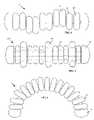
- FIG. 1is a side view of an interstitial marker according to an embodiment of the present invention.
- FIGS. 2A-2Dare side views of tips on an interstitial marker according to embodiments of the present invention.
- FIGS. 3A-3Eare side and cross-sectional views of rings for an interstitial marker according to embodiments of the present invention.
- FIG. 4is a side view of an interstitial marker according to a second embodiment of the present invention.
- FIG. 5is a side view of an interstitial marker according to a third embodiment of the present invention.
- FIG. 6is a side view of an interstitial marker according to an embodiment of the present invention.
- FIG. 7is a side view of an interstitial marker according to a fourth embodiment of the present invention.
- a fiducial or interstitial marker 1is formed of a plurality of rings 20 , 21 , 22 , as illustrated in FIG. 1 .
- the rings 20 , 21 , 22may be of different sizes and shapes, as discussed below.
- Each of the rings 20 , 21 , 22includes a central hole.
- the central holemay be axially centered, as illustrated in FIG. 1 , or may be off-set at any position in the ring.
- the ringsmay have outside diameters ranging from 0.25 mm to 2.00 mm.
- the wall thicknesses of the ringsmay range from 0.025 mm to 0.95 mm.
- the ring wire widths(when seen from the side as illustrated in FIG.
- markersmay range from 0.001 cm to 10.0 cm. Typically, markers range from 3.0 mm to 10.0 cm. The widths, number and spacing of the rings are adjusted to obtain a marker of desired length. Although all of the rings in FIG. 1 are illustrated as being of similar size, shape and width. A single marker may include different rings.
- the ringsmay be formed of various materials which are visible under different imaging modalities. Such materials include gold, gold-gallium, platinum, platinum-gold-iridium, platinum-tungsten, platinum-iridium, platinum-nickel, palladium, rhodium, platinum-rhodium, platinum ruthenium, tantalum, 304 stainless steel, 316 stainless steel, 1605, MP35N, Nitinol, and plastic.
- the size and material of the ringsmay be selected based upon the primary imaging modality being used.
- the rings 20 , 21 , 22are held in place by a ribbon 30 which passes through the central holes in the rings.
- the ribbon 30prevents the marker from compressing or elongating.
- the ribbon 30can be created in different forms such as round wire, flat wire, braided wire or a tubular member.
- the ribbonmay be of any size up to the inner diameters of the rings. According to embodiments of the invention, the diameter of the ribbon ranges from 0.001 mm to 1.00 mm.
- the ribbon 30is of a material which is visible in an imaging modality, such as the materials set forth above with respect to the rings. It may be of the same material as the rings or a different material.
- Materials for the rings and ribbonpreferably include dense precious metals, such as gold, platinum, tungsten iridium, rhodium and palladium, because these metals are visible under various imaging modalities.
- the materialscan be radiopaque, visible under ultrasound, visible under diagnostic X-ray, and visible under therapeutic X-ray. Alloys of such metals may also be used.
- Some or all of the components of the markermay use materials which are not as visible but have other beneficial properties.
- stainless steel and Nitinolmay be used since they have specific mechanical properties, such as strength and resistance to deformation, which may be useful in a marker.
- the ringscan be configured from biocompatible material for implantation.
- Tips 10 , 11are connected to each end of the ribbon 30 .
- the tips 10 , 11may be of various shapes as illustrated in FIGS. 2A-2D .
- the tipscan be configured as having a D-shaped cross-section 110 ( FIG. 2A ), a trapezoid shaped cross-section 210 ( FIG. 2B ), a disk-shaped cross-section 310 ( FIG. 2C ), or a triangular-shaped cross-section 410 ( FIG. 2D ).
- the same shapemay be used for both tips 10 , 11 or different shapes may be used on each end of the ribbon 30 .
- the shape of the tips 10 , 11may differentiate the ends for use in imaging the marker. The shapes may also be used to assist with anchoring the marker in place.
- the tips 10 , 11may be of the same or different materials as the ribbon, rings or each other.
- the rings 20 , 21 , 22 of the fiducial markermay exist in different forms. As illustrated in FIG. 1 , the rings may be round circular rings.
- FIGS. 3A-3Eillustrate other embodiments for the rings.
- FIG. 3Aillustrates a round ring 120 as in FIG. 1 .
- FIG. 3Billustrates a flat ring 220 having a larger central hole.
- FIG. 3Cillustrates a spherical ring 320 with a small central hole. Rings may be formed as a solid or in a braided form 420 as illustrated in FIG. 3D . Rings many have different widths.
- FIG. 3Eillustrates a tubular ring 520 similar to the flat ring 220 of FIG. 3B , but having a greater length.
- 3A-3Eare merely illustrative of possible configurations for the rings. Any size and shape rings may be used. The selected form for the rings may depend upon the intended imaging modalities. The shapes and configurations of rings may have different appearances under different imaging modalities.
- the ribbon 30can be independent of the rings allowing free movement along the length.
- the ribboncan also be joined to some or all of the rings creating a spine for the rings.
- a spineforces all of the sections connected to it to be in the same plane. This is advantageous if one desires to have sections that can ‘float’ independently of the rest of the sections.
- the floating sectionsprovide additional anchoring power to the marker and minimize the tendency of the coil to move in tissue.
- the ribbonmay be connected to the rings in an offset pattern, as illustrated in FIG. 4 .
- the ringsmay be connected to the ribbon out of phase.
- the ringsmay float on the ribbon so that they may be out of phase. Allowing or attaching the rings out of phase provides for enhanced stability in tissue.
- the tips 10 , 11can be eliminated from the marker if the ribbon is attached to the outermost rings.
- FIG. 5illustrates another embodiment of the fiducial marker 100 of the present invention.
- a first set of rings 40are of one size or shape.
- a second set of rings 45 ofare of a different size or shape.
- the use of different sizes or shapes of rings within a single markerprovides for enhanced stability in tissue.
- the ordering of the different size or shape ringsmay be varied.
- more than two sizes and/or shapes of ringscould be used in a marker.
- the use of the rings with a ribbonallows the marker to be flexible. Depending upon the spacing between the rings and the length of the ribbons, the marker may have significant flexibility, as illustrated in FIG. 6 .
- a fiducial marker 200includes at least one helical coil 50 .
- a ribbon 30is positioned within the coil 50 .
- the turns of the coil 50function in the same manner as the rings of the prior embodiments. Tips 10 , 11 are connected to either end of the ribbon 30 to hold the coil in place.
- the ribboncan float within the coil or can be attached to turns of the coil. By attaching the ends of the ribbon 30 to the outer turns of the coil 50 , the tips 10 , 11 can be eliminated.
- multiple coils 50are used in a single marker.
Landscapes
- Health & Medical Sciences (AREA)
- Surgery (AREA)
- Life Sciences & Earth Sciences (AREA)
- Heart & Thoracic Surgery (AREA)
- Molecular Biology (AREA)
- Oral & Maxillofacial Surgery (AREA)
- Engineering & Computer Science (AREA)
- Biomedical Technology (AREA)
- Nuclear Medicine, Radiotherapy & Molecular Imaging (AREA)
- Medical Informatics (AREA)
- Pathology (AREA)
- Animal Behavior & Ethology (AREA)
- General Health & Medical Sciences (AREA)
- Public Health (AREA)
- Veterinary Medicine (AREA)
- Magnetic Resonance Imaging Apparatus (AREA)
- Media Introduction/Drainage Providing Device (AREA)
Abstract
Description
Claims (17)
Priority Applications (1)
| Application Number | Priority Date | Filing Date | Title |
|---|---|---|---|
| US11/779,918US8320995B2 (en) | 2007-04-26 | 2007-07-19 | Fiducial marker with rings |
Applications Claiming Priority (3)
| Application Number | Priority Date | Filing Date | Title |
|---|---|---|---|
| US91421307P | 2007-04-26 | 2007-04-26 | |
| US91481307P | 2007-04-30 | 2007-04-30 | |
| US11/779,918US8320995B2 (en) | 2007-04-26 | 2007-07-19 | Fiducial marker with rings |
Publications (2)
| Publication Number | Publication Date |
|---|---|
| US20080269601A1 US20080269601A1 (en) | 2008-10-30 |
| US8320995B2true US8320995B2 (en) | 2012-11-27 |
Family
ID=39887812
Family Applications (1)
| Application Number | Title | Priority Date | Filing Date |
|---|---|---|---|
| US11/779,918Active2030-08-25US8320995B2 (en) | 2007-04-26 | 2007-07-19 | Fiducial marker with rings |
Country Status (1)
| Country | Link |
|---|---|
| US (1) | US8320995B2 (en) |
Cited By (16)
| Publication number | Priority date | Publication date | Assignee | Title |
|---|---|---|---|---|
| CN103691066A (en)* | 2013-12-27 | 2014-04-02 | 成都军区昆明总医院 | Gold labeling implant and manufacture method thereof |
| US8784433B2 (en) | 2002-06-17 | 2014-07-22 | Senorx, Inc. | Plugged tip delivery tube for marker placement |
| USD715442S1 (en) | 2013-09-24 | 2014-10-14 | C. R. Bard, Inc. | Tissue marker for intracorporeal site identification |
| USD715942S1 (en) | 2013-09-24 | 2014-10-21 | C. R. Bard, Inc. | Tissue marker for intracorporeal site identification |
| USD716450S1 (en) | 2013-09-24 | 2014-10-28 | C. R. Bard, Inc. | Tissue marker for intracorporeal site identification |
| USD716451S1 (en) | 2013-09-24 | 2014-10-28 | C. R. Bard, Inc. | Tissue marker for intracorporeal site identification |
| US9042965B2 (en) | 2006-12-18 | 2015-05-26 | C. R. Bard, Inc. | Biopsy marker with in situ-generated imaging properties |
| US9044162B2 (en) | 1999-02-02 | 2015-06-02 | Senorx, Inc. | Marker delivery device with releasable plug |
| US9149341B2 (en) | 1999-02-02 | 2015-10-06 | Senorx, Inc | Deployment of polysaccharide markers for treating a site within a patient |
| US9820824B2 (en) | 1999-02-02 | 2017-11-21 | Senorx, Inc. | Deployment of polysaccharide markers for treating a site within a patent |
| US9860392B2 (en) | 2015-06-05 | 2018-01-02 | Silicon Laboratories Inc. | Direct-current to alternating-current power conversion |
| US9901415B2 (en) | 2006-12-12 | 2018-02-27 | C. R. Bard, Inc. | Multiple imaging mode tissue marker |
| US9936892B1 (en) | 2009-05-04 | 2018-04-10 | Cortex Manufacturing Inc. | Systems and methods for providing a fiducial marker |
| US10172674B2 (en) | 1999-02-02 | 2019-01-08 | Senorx, Inc. | Intracorporeal marker and marker delivery device |
| US10258428B2 (en) | 2008-12-30 | 2019-04-16 | C. R. Bard, Inc. | Marker delivery device for tissue marker placement |
| US10786604B2 (en) | 2008-09-23 | 2020-09-29 | Senorx, Inc. | Porous bioabsorbable implant |
Families Citing this family (20)
| Publication number | Priority date | Publication date | Assignee | Title |
|---|---|---|---|---|
| US9386942B2 (en) | 2009-06-26 | 2016-07-12 | Cianna Medical, Inc. | Apparatus, systems, and methods for localizing markers or tissue structures within a body |
| EP3106089B1 (en) | 2009-06-26 | 2020-12-02 | Cianna Medical, Inc. | System for localizing markers or tissue structures within a body |
| SE535831C2 (en)* | 2011-05-09 | 2013-01-08 | Ingemar Naeslund | position Cursor |
| CA2835412A1 (en)* | 2011-05-11 | 2012-11-15 | The Regents Of The University Of California | Fiduciary markers and methods of placement |
| US9713437B2 (en) | 2013-01-26 | 2017-07-25 | Cianna Medical, Inc. | Microwave antenna apparatus, systems, and methods for localizing markers or tissue structures within a body |
| US10660542B2 (en) | 2013-01-26 | 2020-05-26 | Cianna Medical, Inc. | RFID markers and systems and methods for identifying and locating them |
| US9301723B2 (en) | 2013-03-15 | 2016-04-05 | Covidien Lp | Microwave energy-delivery device and system |
| US9119650B2 (en) | 2013-03-15 | 2015-09-01 | Covidien Lp | Microwave energy-delivery device and system |
| US9161814B2 (en)* | 2013-03-15 | 2015-10-20 | Covidien Lp | Microwave energy-delivery device and system |
| US10624697B2 (en) | 2014-08-26 | 2020-04-21 | Covidien Lp | Microwave ablation system |
| US10610326B2 (en) | 2015-06-05 | 2020-04-07 | Cianna Medical, Inc. | Passive tags, and systems and methods for using them |
| US10813692B2 (en) | 2016-02-29 | 2020-10-27 | Covidien Lp | 90-degree interlocking geometry for introducer for facilitating deployment of microwave radiating catheter |
| AU2017226261A1 (en) | 2016-03-03 | 2018-10-04 | Cianna Medical, Inc. | Implantable markers, and systems and methods for using them |
| JP7030714B2 (en) | 2016-04-06 | 2022-03-07 | シアナ メディカル,インク. | Reflector markers, and systems and methods for recognizing and locating them |
| CN106730420A (en)* | 2017-02-06 | 2017-05-31 | 中国人民解放军总医院 | Tumor marker device |
| WO2018175667A1 (en) | 2017-03-21 | 2018-09-27 | Cianna Medical, Inc. | Reflector markers and systems and methods for identifying and locating them |
| US11883150B2 (en) | 2018-09-06 | 2024-01-30 | Cianna Medical, Inc. | Systems for identifying and locating reflectors using orthogonal sequences of reflector switching |
| CA3156428A1 (en) | 2019-11-05 | 2021-05-14 | Cianna Medical, Inc. | Systems and methods for imaging a body region using implanted markers |
| JP7403424B2 (en)* | 2020-09-29 | 2023-12-22 | 日本ピストンリング株式会社 | Manufacturing method for medical markers |
| WO2023007702A1 (en)* | 2021-07-30 | 2023-02-02 | 株式会社マトリックス細胞研究所 | Magnetic marker set and method for arranging magnetic marker |
Citations (5)
| Publication number | Priority date | Publication date | Assignee | Title |
|---|---|---|---|---|
| US6371904B1 (en)* | 1998-12-24 | 2002-04-16 | Vivant Medical, Inc. | Subcutaneous cavity marking device and method |
| US20020087101A1 (en)* | 2000-01-04 | 2002-07-04 | Barrick Earl Frederick | System and method for automatic shape registration and instrument tracking |
| US20030028095A1 (en)* | 1999-04-15 | 2003-02-06 | Steve Tulley | Magnetic resonance imaging probe |
| US20050020916A1 (en)* | 2003-06-06 | 2005-01-27 | Macfarlane K. Angela | Subcutaneous biopsy cavity marker device |
| US20070093726A1 (en)* | 2004-10-13 | 2007-04-26 | Leopold Phillip M | Site marker visible under multiple modalities |
- 2007
- 2007-07-19USUS11/779,918patent/US8320995B2/enactiveActive
Patent Citations (5)
| Publication number | Priority date | Publication date | Assignee | Title |
|---|---|---|---|---|
| US6371904B1 (en)* | 1998-12-24 | 2002-04-16 | Vivant Medical, Inc. | Subcutaneous cavity marking device and method |
| US20030028095A1 (en)* | 1999-04-15 | 2003-02-06 | Steve Tulley | Magnetic resonance imaging probe |
| US20020087101A1 (en)* | 2000-01-04 | 2002-07-04 | Barrick Earl Frederick | System and method for automatic shape registration and instrument tracking |
| US20050020916A1 (en)* | 2003-06-06 | 2005-01-27 | Macfarlane K. Angela | Subcutaneous biopsy cavity marker device |
| US20070093726A1 (en)* | 2004-10-13 | 2007-04-26 | Leopold Phillip M | Site marker visible under multiple modalities |
Cited By (23)
| Publication number | Priority date | Publication date | Assignee | Title |
|---|---|---|---|---|
| US10172674B2 (en) | 1999-02-02 | 2019-01-08 | Senorx, Inc. | Intracorporeal marker and marker delivery device |
| US9044162B2 (en) | 1999-02-02 | 2015-06-02 | Senorx, Inc. | Marker delivery device with releasable plug |
| US9820824B2 (en) | 1999-02-02 | 2017-11-21 | Senorx, Inc. | Deployment of polysaccharide markers for treating a site within a patent |
| US9861294B2 (en) | 1999-02-02 | 2018-01-09 | Senorx, Inc. | Marker delivery device with releasable plug |
| US9149341B2 (en) | 1999-02-02 | 2015-10-06 | Senorx, Inc | Deployment of polysaccharide markers for treating a site within a patient |
| US8784433B2 (en) | 2002-06-17 | 2014-07-22 | Senorx, Inc. | Plugged tip delivery tube for marker placement |
| US11471244B2 (en) | 2006-12-12 | 2022-10-18 | C.R. Bard, Inc. | Multiple imaging mode tissue marker |
| US10682200B2 (en) | 2006-12-12 | 2020-06-16 | C. R. Bard, Inc. | Multiple imaging mode tissue marker |
| US9901415B2 (en) | 2006-12-12 | 2018-02-27 | C. R. Bard, Inc. | Multiple imaging mode tissue marker |
| US9042965B2 (en) | 2006-12-18 | 2015-05-26 | C. R. Bard, Inc. | Biopsy marker with in situ-generated imaging properties |
| US11833275B2 (en) | 2008-09-23 | 2023-12-05 | Senorx, Inc. | Porous bioabsorbable implant |
| US10786604B2 (en) | 2008-09-23 | 2020-09-29 | Senorx, Inc. | Porous bioabsorbable implant |
| US10258428B2 (en) | 2008-12-30 | 2019-04-16 | C. R. Bard, Inc. | Marker delivery device for tissue marker placement |
| US11779431B2 (en) | 2008-12-30 | 2023-10-10 | C. R. Bard, Inc. | Marker delivery device for tissue marker placement |
| US10952632B2 (en) | 2009-05-04 | 2021-03-23 | Cortex Manufacturing Inc. | Imaging fiducial markers and methods |
| US9936892B1 (en) | 2009-05-04 | 2018-04-10 | Cortex Manufacturing Inc. | Systems and methods for providing a fiducial marker |
| USD715942S1 (en) | 2013-09-24 | 2014-10-21 | C. R. Bard, Inc. | Tissue marker for intracorporeal site identification |
| USD716450S1 (en) | 2013-09-24 | 2014-10-28 | C. R. Bard, Inc. | Tissue marker for intracorporeal site identification |
| USD715442S1 (en) | 2013-09-24 | 2014-10-14 | C. R. Bard, Inc. | Tissue marker for intracorporeal site identification |
| USD716451S1 (en) | 2013-09-24 | 2014-10-28 | C. R. Bard, Inc. | Tissue marker for intracorporeal site identification |
| CN103691066A (en)* | 2013-12-27 | 2014-04-02 | 成都军区昆明总医院 | Gold labeling implant and manufacture method thereof |
| CN103691066B (en)* | 2013-12-27 | 2016-08-17 | 成都军区昆明总医院 | A kind of gold mark implant and manufacture method thereof |
| US9860392B2 (en) | 2015-06-05 | 2018-01-02 | Silicon Laboratories Inc. | Direct-current to alternating-current power conversion |
Also Published As
| Publication number | Publication date |
|---|---|
| US20080269601A1 (en) | 2008-10-30 |
Similar Documents
| Publication | Publication Date | Title |
|---|---|---|
| US8320995B2 (en) | Fiducial marker with rings | |
| JP4918494B2 (en) | Medical device with improved torque response and curve retention, and method for manufacturing the same | |
| US8038705B2 (en) | Intraluminal medical device having improved visibility | |
| JP4928948B2 (en) | Composite catheter blade | |
| EP1960012B1 (en) | Implantable medical device using palladium | |
| US9456878B2 (en) | Subcutaneous biopsy cavity marker device | |
| EP2918306A1 (en) | Guide wire | |
| EP2308407A1 (en) | Elongated marker for soft tissue volume identification | |
| JPH09276413A5 (en) | ||
| EP3369368A1 (en) | Multi-electrode assembly | |
| JP2008520278A (en) | Flexible linear mapping catheter with stabilizing tip | |
| JP2007500068A (en) | Medical device having segment structure | |
| JP2004275766A (en) | Multifunctional catheter handle | |
| JP2011512994A (en) | Improved visualization of catheters visible under ultrasound imaging | |
| US12005205B2 (en) | Guidewires for medical devices | |
| JP2010516404A5 (en) | ||
| CN107802942B (en) | Medical guide wire | |
| WO2024083064A1 (en) | Blood vessel implant | |
| JP2012029872A (en) | Catheter | |
| US20150206622A1 (en) | Stranded wire and guidewire employing the same | |
| JP6533753B2 (en) | Biomedical marker and biomedical marker insertion instrument set | |
| US12414836B2 (en) | Implantable marker | |
| EP1948063B1 (en) | Marker for marking an area in body tissue | |
| JPH08112356A (en) | Guide wire | |
| JP2021000256A (en) | Hollow shaft and catheter |
Legal Events
| Date | Code | Title | Description |
|---|---|---|---|
| STCF | Information on status: patent grant | Free format text:PATENTED CASE | |
| AS | Assignment | Owner name:ONC SOLUTIONS, INC., MASSACHUSETTS Free format text:ASSIGNMENT OF ASSIGNORS INTEREST;ASSIGNOR:SCHWAMB, JOHN P., JR.;REEL/FRAME:030121/0595 Effective date:20130213 | |
| AS | Assignment | Owner name:RADIOMED CORP., TENNESSEE Free format text:ASSIGNMENT OF ASSIGNORS INTEREST;ASSIGNOR:ONC SOLUTIONS, INC.;REEL/FRAME:033339/0601 Effective date:20130718 | |
| FEPP | Fee payment procedure | Free format text:PAT HOLDER NO LONGER CLAIMS SMALL ENTITY STATUS, ENTITY STATUS SET TO UNDISCOUNTED (ORIGINAL EVENT CODE: STOL); ENTITY STATUS OF PATENT OWNER: LARGE ENTITY | |
| FPAY | Fee payment | Year of fee payment:4 | |
| AS | Assignment | Owner name:RADIOMED CORP., TENNESSEE Free format text:CORRECTIVE ASSIGNMENT TO CORRECT THE RECEIVING PARTY ADDRESS PREVIOUSLY RECORDED AT REEL: 33339 FRAME: 601. ASSIGNOR(S) HEREBY CONFIRMS THE ASSIGNMENT;ASSIGNOR:ONC SOLUTIONS, INC.;REEL/FRAME:051209/0668 Effective date:20130718 | |
| AS | Assignment | Owner name:WINTRUST BANK, N.A, AS AGENT, ILLINOIS Free format text:FOURTH AMENDED AND RESTATED CONFIRMATORY GRANT OF SECURITY INTEREST IN INTELLECTUAL PROPERTY;ASSIGNOR:RADIOMED CORPORATION;REEL/FRAME:051459/0391 Effective date:20191216 | |
| MAFP | Maintenance fee payment | Free format text:PAYMENT OF MAINTENANCE FEE, 8TH YEAR, LARGE ENTITY (ORIGINAL EVENT CODE: M1552); ENTITY STATUS OF PATENT OWNER: LARGE ENTITY Year of fee payment:8 | |
| AS | Assignment | Owner name:SCP INTERVENTIONAL RADIOLOGY, LLC, ILLINOIS Free format text:RELEASE BY SECURED PARTY;ASSIGNOR:WINTRUST BANK, N.A.;REEL/FRAME:061803/0869 Effective date:20220930 Owner name:RADIOMED CORPORATION, TENNESSEE Free format text:RELEASE BY SECURED PARTY;ASSIGNOR:WINTRUST BANK, N.A.;REEL/FRAME:061803/0869 Effective date:20220930 Owner name:SCP IR ACQUISITION, LLC, UNITED KINGDOM Free format text:RELEASE BY SECURED PARTY;ASSIGNOR:WINTRUST BANK, N.A.;REEL/FRAME:061803/0869 Effective date:20220930 Owner name:IZI MEDICAL PRODUCTS, LLC, MARYLAND Free format text:RELEASE BY SECURED PARTY;ASSIGNOR:WINTRUST BANK, N.A.;REEL/FRAME:061803/0869 Effective date:20220930 | |
| MAFP | Maintenance fee payment | Free format text:PAYMENT OF MAINTENANCE FEE, 12TH YEAR, LARGE ENTITY (ORIGINAL EVENT CODE: M1553); ENTITY STATUS OF PATENT OWNER: LARGE ENTITY Year of fee payment:12 | |
| AS | Assignment | Owner name:IZI MEDICAL PRODUCTS, LLC, MARYLAND Free format text:ASSIGNMENT OF ASSIGNORS INTEREST;ASSIGNOR:RADIOMED CORPORATION;REEL/FRAME:070083/0827 Effective date:20250130 |