US8320344B2 - System and method for provisioning telecommunications services between an access point and a telecommunications network and providing a missing information notification - Google Patents
System and method for provisioning telecommunications services between an access point and a telecommunications network and providing a missing information notificationDownload PDFInfo
- Publication number
- US8320344B2 US8320344B2US12/395,593US39559309AUS8320344B2US 8320344 B2US8320344 B2US 8320344B2US 39559309 AUS39559309 AUS 39559309AUS 8320344 B2US8320344 B2US 8320344B2
- Authority
- US
- United States
- Prior art keywords
- access point
- network
- telecommunications
- address
- missing information
- Prior art date
- Legal status (The legal status is an assumption and is not a legal conclusion. Google has not performed a legal analysis and makes no representation as to the accuracy of the status listed.)
- Active, expires
Links
Images


Classifications
- H—ELECTRICITY
- H04—ELECTRIC COMMUNICATION TECHNIQUE
- H04W—WIRELESS COMMUNICATION NETWORKS
- H04W8/00—Network data management
- H04W8/02—Processing of mobility data, e.g. registration information at HLR [Home Location Register] or VLR [Visitor Location Register]; Transfer of mobility data, e.g. between HLR, VLR or external networks
- H04W8/06—Registration at serving network Location Register, VLR or user mobility server
- H—ELECTRICITY
- H04—ELECTRIC COMMUNICATION TECHNIQUE
- H04L—TRANSMISSION OF DIGITAL INFORMATION, e.g. TELEGRAPHIC COMMUNICATION
- H04L12/00—Data switching networks
- H04L12/66—Arrangements for connecting between networks having differing types of switching systems, e.g. gateways
- H—ELECTRICITY
- H04—ELECTRIC COMMUNICATION TECHNIQUE
- H04W—WIRELESS COMMUNICATION NETWORKS
- H04W4/00—Services specially adapted for wireless communication networks; Facilities therefor
- H04W4/02—Services making use of location information
- H—ELECTRICITY
- H04—ELECTRIC COMMUNICATION TECHNIQUE
- H04W—WIRELESS COMMUNICATION NETWORKS
- H04W4/00—Services specially adapted for wireless communication networks; Facilities therefor
- H04W4/02—Services making use of location information
- H04W4/029—Location-based management or tracking services
- H—ELECTRICITY
- H04—ELECTRIC COMMUNICATION TECHNIQUE
- H04W—WIRELESS COMMUNICATION NETWORKS
- H04W12/00—Security arrangements; Authentication; Protecting privacy or anonymity
- H04W12/08—Access security
- H—ELECTRICITY
- H04—ELECTRIC COMMUNICATION TECHNIQUE
- H04W—WIRELESS COMMUNICATION NETWORKS
- H04W88/00—Devices specially adapted for wireless communication networks, e.g. terminals, base stations or access point devices
- H04W88/08—Access point devices
Definitions
- IPInternet Protocol
- VoIPVoice over Internet Protocol
- these IP-based wireless access networksmay be based on IEEE 802.16 (WiMAX), IEEE 802.20 Mobile Broadband Wireless Access (MBWA), Ultra Wideband (UWB), 802.11 wireless fidelity (Wi-Fi), Bluetooth, and similar standards.
- UMAUnlicensed Mobile Access
- 3GPP3rd Generation Partnership Project
- GANGeneric Access Network
- GSMGlobal System for Mobile Communications
- IP-based wireless networksinto one seamless service (with one mobile device, one user interface, and a common set of network services for both voice and data).
- GSMGlobal System for Mobile Communications
- One goal of UMAis to allow subscribers to move transparently between cellular networks and IP-based wireless networks with seamless voice and data session continuity, similar to the way that they can transparently move between cells within the cellular network. Seamless in-call handover between the IP-based wireless network and the cellular network ensures that the user's location and mobility do not affect the services delivered to the user.
- UMA technologyeffectively creates a parallel radio access network, the UMA network, which interfaces with the mobile core network using standard mobility-enabled interfaces.
- UMAcan replace a system's GSM radio technology on the lower protocol layers with a wireless Local Area Network (LAN), or similar technology.
- a call or other communicationmay be tunneled to the Mobile Switching Center (MSC) of a mobile service provider via an access point (e.g., a Wi-Fi access point or a femtocell connected to a modem via the Internet) and gateway (e.g., a UMA network controller).
- MSCMobile Switching Center
- gatewaye.g., a UMA network controller
- the existing service provider's business support systems (BSS), service delivery systems, content services, regulatory compliance systems, and operation support systems (OSS)can support the UMA network without change.
- BSSbusiness support systems
- OSSoperation support systems
- service enhancements and technology evolution of the mobile core networkapply transparently to both cellular access and UMA.
- FIG. 1illustrates aspects of a sample network system that allows VoIP-based communications in conjunction with a public switched telephone network (PSTN).
- PSTNpublic switched telephone network
- FIG. 2illustrates a sample converged wireless network system that combines a cellular network with an IP-based wireless telecommunications network.
- FIG. 3illustrates the back panel of an access point capable of supporting two landline telephones in addition to a wireless connection.
- FIG. 4illustrates a timing diagram of actions in a UMA network for provisioning telecommunications services.
- FIG. 5illustrates a block diagram of an access point capable of selectively provisioning a connection for a landline telephone.
- FIG. 6illustrates a process for selectively provisioning telecommunications services between a landline telephone and an IP-based network.
- FIG. 7illustrates a logical block diagram of a system for provisioning telecommunications services in response to a request received from an access point.
- FIG. 8illustrates a process for provisioning telecommunications services in response to a request received from an access point.
- FIG. 1illustrates aspects of a sample network system 100 , including multiple telecommunications networks, that allows VoIP-based communications in conjunction with a public switched telephone network (PSTN) 102 .
- a telecommunications networkmay include any network suitable for enabling transmission of signals over a distance.
- the telecommunications networks discussedmay be wired or wireless, circuit-switched or packet-switched, and may use licensed, semilicensed, or unlicensed wireless bands.
- the network system 100includes at least one access point 104 .
- the access point 104may be public or private and may be located, for example, in a subscriber's residence (e.g., home, apartment, or other residence), in a public location (e.g., coffee shops, retail stores, libraries, or schools), or in corporate or other private locations.
- the access point 104can accept communications 106 from at least one suitably configured telecommunications device 108 (e.g., a VoIP device).
- the access point 104includes a wireless router 110 and a broadband modem 112 that enable connection to an Internet Protocol (IP) network 114 .
- IP network 114may comprise one or more public networks or private networks, or a combination of public and private networks.
- the access point 104receives IP packets from the telecommunications device 108 . These IP packets are then transported through the IP network 114 to a signaling gateway 116 , which in the example of FIG. 1 is operated by a telecommunications service provider. At the signaling gateway 116 , the IP packets are converted to a traditional phone service signal. The phone service signal is then conveyed to a recipient via the PSTN 102 .
- the network system 100 of FIG. 1also includes a call controller 118 that provides call logic and call control functions for communications sent through the system and an application server 120 that provides logic and execution of one or more applications or services offered by the telecommunications service provider, such as applications that implement various access and security rules.
- a telecommunications service providermanages both the call controller 118 and the application server 120 .
- FIG. 2illustrates a sample converged wireless network system that combines a cellular network with an IP-based wireless telecommunications network.
- the cellular service providermaintains a large degree of system compatibility even though it uses an IP-based network.
- the various systems of the cellular service provider that deliver content and handle mobilitymay not even need to be aware that a subscriber's mobile device is on an IP-based wireless telecommunications network. Instead, the various systems of the cellular service provider assume that the mobile device is on its native cellular network.
- the IP networkis, therefore, abstracted with respect to the cellular network, regardless of whether the mobile device connects to the cellular network via a base station (e.g., for licensed spectrum access) or a wireless access point (e.g., for licensed, semilicensed, and/or unlicensed spectrum access-such as spectrums for IP-based wireless telecommunications).
- a base statione.g., for licensed spectrum access
- a wireless access pointe.g., for licensed, semilicensed, and/or unlicensed spectrum access-such as spectrums for IP-based wireless telecommunications.
- the cellular service providermaintains a large degree of system compatibility even though it uses an IP-based network.
- a sample network system 200combines a cellular telephone network 202 (such as a GSM network) and an IP network 204 in a UMA-type configuration that provides service to the user of a mobile device 206 or a landline telephone 236 .
- Such servicemay include voice services and also supplementary services, such as call forwarding, call waiting, text messaging services (e.g., Short Message Service (SMS)), and data-based services like ringtone downloads, game downloads, picture messaging, email, and web browsing.
- SMSShort Message Service
- data-based serviceslike ringtone downloads, game downloads, picture messaging, email, and web browsing.
- the described network system 200accepts registration requests from the mobile device 206 .
- the accepted registration requestscan be requests to either the cellular telephone network 202 or to the IP network 204 .
- the cellular telephone network 202includes one or more cell towers 208 that are configured to accept cellular communications 210 from the mobile device 206 .
- the cell towers 208are connected to a base station controller 212 (such as a base station controller/radio network controller (BSC/RNC)) via a private network 214 .
- the private network 214can include a variety of connections (not shown) such as T1 lines, a wide area network (WAN), a local area network (LAN), various network switches, and other similar components.
- the base station controller 212controls communication traffic to a carrier network 216 , where all communications are managed (including both cellular and IP-based communications).
- Components of the carrier network 216 in this exampleinclude a switch (e.g., a mobile switching center (MSC)) 218 , which is configured to control data/call flows and perform load balancing, as well as other functions.
- the carrier network 216may also include a variety of system databases, such as an operation support subsystem (OSS) database 220 , a business support system (BSS) database 222 , and a home location register (HLR) 224 , or other central subscriber database that contains details of a carrier's subscribers for billing, call logging, etc.
- OSSoperation support subsystem
- BSSbusiness support system
- HLRhome location register
- the sample network system 200further includes one or more access points 226 that can accept IP-based communications 228 from the mobile device 206 .
- each access point 226can be configured as part of a network in one or more locations such as a public network 230 , a home network 232 , or a private business network 234 .
- Each access point 226is coupled to the IP network 204 through, for example, a broadband connection (not shown), such as a Digital Subscriber Line (DSL) modem, a cable modem, a satellite modem, or any other broadband device.
- the access pointsmay communicate with mobile devices wirelessly via any licensed, semilicensed or unlicensed spectrum (e.g., a WiFi access point or a femtocell access point), or may provide only wired communication.
- the access points 226may be configured to provide telecommunications services to any type of customer-premises equipment (CPE).
- CPEcustomer-premises equipment
- a CPEis any terminal or equipment located at a subscriber's premises (e.g. in a home or office) and connected with a carrier telecommunications network.
- CPEmay include, for example, a landline telephone, a cordless telephone, a mobile device operating within the home, a broadband modem, or a set-top box.
- the access points 226may be configured with one or more landline telephone connectors.
- FIG. 3illustrates the back panel of an access point 226 capable of supporting two landline telephones (e.g., traditional landline telephones and cordless telephones) in addition to a wireless connection.
- the access point 226includes a WAN connector 304 , which connects the access point 226 to the IP network 204 .
- the access point 226also includes a plurality of data connectors 306 that connect to computers or other devices and are used to carry data traffic.
- the access point 226may have one or more antennas 308 that support wireless connections for data transmission, such as for an IP-based telecommunications connection. Alternatively, the access point 226 may have no antennas and may only support wired connections.
- the access point 226also includes two telephone connectors 302 , which can accept a cable connecting to a landline telephone. In most cases, this is implemented as an RJ-11 connector, but one skilled in the art will appreciate that other standard connectors could be used, including an RJ-14, RJ-25, or RJ-45 connector.
- the access point 226may also include a port, slot, or socket (shown in FIG. 5 ) configured to accept an identifier module that stores data associated with a subscriber or a voice connection, such as a subscriber identifier (e.g., an International Mobile Subscriber Identifier (IMSI)).
- IMSIInternational Mobile Subscriber Identifier
- the access point 226may also support an alternate identifier, such as a software Subscriber Identity Module (SIM) or other identifier.
- SIMsoftware Subscriber Identity Module
- the identifier modulemay include a tamper-resistant memory that may store information used to enable a device to connect to the carrier network 216 and authenticate the device to the carrier network 216 .
- the subscriber identifiermay be a unique or rare secure identification number associated with a subscriber, an organization, or a calling plan.
- the slotis configured to accept a SIM card similar to those used for GSM mobile devices.
- the access point 226may include a separate slot for each telephone connector 302 to allow each landline telephone 236 to be separately authorized.
- the telephone connectors 302may be implemented as a local wireless connection using licensed, semilicensed, or unlicensed wireless bands.
- the access point 226may include a radio as the telephone connector, which is configured to communicate directly with a cordless telephone handset using an unlicensed wireless band.
- the access point 226may communicate with a mobile device (e.g., a cellular telephone or smartphone) using a licensed band.
- the access point 226may then be configured to provide telecommunications services using connection information (e.g., telephone number, subscriber identifier, etc.) associated with the access point 226 , rather than connection information associated with the cordless telephone handset/mobile device/etc.
- connection informatione.g., telephone number, subscriber identifier, etc.
- This implementationhas the advantage of allowing a user to use a cordless telephone handset without requiring a separate base station. It also allows a user to use a mobile device as a handset even if the mobile device is not configured to directly connect to the carrier network.
- the access point 226may also include one or more user indicators to provide status information or error notifications to a user (shown in FIG. 5 ).
- the access point 226may provide information by enabling, disabling, or changing a color of one or more indicator lights 310 .
- the access point 226may include a display screen (e.g., an LCD screen) capable of displaying text describing status or error conditions.
- the access point 226may also provide other user-perceptible indicators, such as an audible indicator.
- the landline telephone 236is connected to the access point 226 with a standard wired connection 238 to one of the telephone connectors 302 .
- the access point 226converts the incoming analog voice signal into digital form and encapsulates the signal for transmission over the IP network 204 .
- the access point 226also communicates with a security gateway 240 or a network controller 242 to enable the landline telephone to make calls through the carrier network 216 .
- the access point 226is generally configured to provision a separate connection for each telephone connector 302 .
- the access point 226includes components to provide the connected landline telephone 236 with a simulation of a Plain Old Telephone Service (POTS) network.
- POTSPlain Old Telephone Service
- the access point 226may act as a POTS end office by providing a dial tone when the user lifts the telephone off the hook if there is a connection to the carrier network.
- the access pointmay also provide the calling name and number for an incoming call by translating the data from the IP-based telecommunications format to the format used by a POTS caller ID service. It may similarly provide the ability to toggle between calls for call waiting using the standard flash hook by translating the POTS signal into the equivalent UMA or GSM format.
- the access point 226may also provide a standard POTS stutter dial tone to indicate new voice mail.
- the access point 226could do this by periodically querying the carrier network 216 to determine whether new voice mail is available and providing the stutter dial tone if the carrier network indicates that there is new voice mail.
- the access point 226may include an indicator (e.g. a flashing light) to notify the user that new voice mail is available.
- informatione.g., data, voice, SMS, etc.
- informationis initially formatted in the native protocol of the cellular telephone network 202 and then encapsulated into IP packets, which are transmitted to the access point 226 and routed through the IP network 204 to the security gateway 240 .
- such transmissionsbypass the existing network of radio towers of the cellular telephone network 202 .
- the access point 226encapsulates the voice signal into IP packets that are then routed through the IP network 204 to the security gateway 240 .
- the security gateway 240controls access to the network controller 242 , which communicates with a data store 246 used to log and access communications data.
- a data store 246used to log and access communications data.
- one function of the network controller 242is to manage access to the carrier network 216 when dealing with an IP-based communication (in a similar manner that the base station controller 212 does for a non-IP-based communication).
- authentication of a request for access by the mobile device 206 or the access point 226 over the IP network 204is handled by the security gateway 240 , which communicates with an authentication, access, and authorization (AAA) module 244 that is most likely associated with the carrier network 216 .
- AAAauthentication, access, and authorization
- Challenges and responses to requests for access by the mobile device 206 or the access point 226are communicated between the HLR 224 and the AAA module 244 .
- the security gateway 240communicates the assignment of an IP address to the mobile device 206 or the access point 226 that requested access. Once the security gateway 240 passes the IP address to the mobile device 206 or the access point 226 , the public IP address assigned to the device is passed to the network controller 242 .
- the network controller 242may query the data store 246 to determine whether the mobile device 206 is authorized to access the IP network 204 .
- Sample identifiersthat may be utilized to determine whether access should be granted include a media access control (MAC) address associated with an access point, a mobile device or subscriber identifier (such as an IMSI), an IP address (or “Public IP address”) associated with the access point, a fully qualified domain name (FQDN), or other similar types of information.
- MACmedia access control
- IMSIan IP address
- FQDNfully qualified domain name
- the data store 246may be a single database, table, or list, or a combination of databases, tables, or lists, such as one for IP addresses 248 , one for MAC addresses 250 , one for subscriber identifiers 252 , and one for FQDNs 254 .
- the data store 246may include “blocked” identifiers as well as “authorized” identifiers. Authorized accesses to the IP-based wireless telecommunications network may be maintained by the network controller 242 in an authorized session table or similar data construct.
- the signaling portion of a communication(e.g., the portion of the communication that governs various overhead aspects of the communication such as, for example, when the call starts, when the call stops, initiating a telephone ring, etc.) is routed through the network controller 242 to the switch 218 , while the voice bearer portion of the communication (e.g., the portion of the communication that contains the actual content (either data or voice information) of the communication) is routed through the network controller 242 to a media gateway 256 .
- the media gateway 256controls the content flow between the service provider and the mobile device 206
- the switch 218controls the signaling flow (or controls the overhead-related flow) between the service provider and the mobile device 206 .
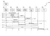
- FIG. 4illustrates an example of a timing diagram 400 of steps in a UMA network for provisioning telecommunications services, including registering a mobile device and facilitating a call from the mobile device 206 .
- the disclosed systemis not limited to UMA services and may include any other service suitable for provisioning telecommunications services.
- the disclosed systemmay also be configured to provide access using licensed frequency bands.
- the call registration processis illustrated by communication steps 402 - 412
- the calling processis illustrated by communication steps 414 - 422 .
- the steps of the timing diagram 400may also be used to support calls from the landline telephone 236 connected to the access point 226 . In those cases, the registration and calling processes are initiated by the access point 226 , rather than the mobile device 206 .
- the mobile device 206 or the access point 226initiates a call by sending a request to register to the security gateway 240 .
- the security gateway 240replies with an authentication challenge communicated back to the mobile device 206 or access point 226 at step 404 .
- the mobile device 206 or access point 226responds to the authentication challenge with a response communicated to the security gateway 240 .
- the security gateway 240communicates a public IP address that is assigned to the access point 226 to the network controller 242 .
- the mobile device 206communicates an identifier (such as the IMSI ID) and a Cell Global Identifier (CGI) record (CGI REAL ) to the security gateway 240 .
- an identifiersuch as the IMSI ID
- CGICell Global Identifier
- the CGI recordis an identifier that uniquely identifies a base station initiating a call through the core network.
- CGI REALis the CGI record for the nearest cell tower 208 .
- CGI REALmay be a hard-coded value unique to the access point 226 or may be selected based on other criteria, such as geographic location.
- the security gateway 240transmits the subscriber identifier, CGI REAL , and the MAC address (MAC AP ) from the access point 226 to the network controller 242 .
- the network controller 242communicates with the data store 246 , which replies with CGI BILLING at step 410 .
- CGI BILLINGis used by the network to ensure that the call is billed correctly.
- the network controller 242may also perform other types of authentication during this step. For example, current Federal Communications Commission regulations require that VoIP connections must be associated with a physical or geographic address (e.g., a street address) in order to enable enhanced 911 emergency services (E911). Thus, the network controller 242 may also confirm that the data store 246 includes an E911 address for the access point 226 before allowing the voice connection. For example, the network controller 242 may use the subscriber identifier as an index to look up an E911 address and reject the connection if no address is found. In some implementations, when provisioning a connection from a mobile device, the network controller 242 may use identifying information associated with the access point (e.g., the MAC address) to find the E911 address.
- identifying information associated with the access pointe.g., the MAC address
- the network controller 242communicates a registration completion message to the mobile device 206 . If the connection is rejected, the network controller 242 responds with a rejection message. In particular, if an E911 address was not found, the network controller 242 provides a missing information notification message informing the access point 226 that required information was not found. In a UMA or GAN system, the missing information notification message is a geolocation unknown message.
- the mobile device 206 or the access point 226communicates with the network controller 242 to request a call at step 414 .
- the network controller 242communicates the subscriber identifier and CGI BILLING to the switch 218 .
- the switch 218authorizes the call at step 418 such that the device can communicate over a communication channel established through the switch 218 at step 420 .
- the callis terminated and the switch 218 communicates a call data record (CDR) to the billing system (e.g., the BSS database 222 ).
- CDRcall data record
- the access point 226can be used to provision a connection for a landline telephone, a cordless telephone, or any mobile device.
- the access point 226sends a provisioning request that includes identifying information such as a subscriber identifier and a MAC address, to the network controller 242 .
- the network controller 242attempts to find a geographic address associated with the connection to be provisioned. If an address is not found, the network controller 242 rejects the connection and sends a missing information notification to the access point 226 .
- the access point 226controls a user indicator (e.g., an indicator light, a display screen, an audible indicator, etc.) to provide error information.
- a user indicatore.g., an indicator light, a display screen, an audible indicator, etc.
- FIG. 5illustrates a block diagram of an access point 226 capable of selectively provisioning a connection for a landline telephone 236 .
- the access point 226includes a network connection component 504 that provides an interface between the access point 226 and the IP network 204 .
- the network connection component 504is connected to the network through a network connection 502 , which may be a hardwired connection (e.g., a cable or DSL connection) or a wireless connection (e.g., a WiMAX connection).
- the network connection component 504may be of any type known in the art, such as an Ethernet network chip.
- the connectionis supported by a standard network protocol stack, such as a TCP/IP stack (not shown).
- the access point 226includes a telephone connector component 512 , which is connected to a telephone cord 510 .
- the telephone connector component 512receives a landline telephone signal through the telephone cord 510 and passes it to other processing components (not shown).
- the telephone connector 512may be a wireless connection using unlicensed spectrum to connect to a cordless phone or a mobile device.
- the other processing componentscan include, for example, a component to convert the analog signal into a digital form and encapsulate the data for transmission.
- the access point 226may also have a wireless LAN (WLAN) radio component 508 , which is connected to one or more antennas 506 .
- the WLAN radio component 508provides wireless networking support to enable mobile devices 206 to connect as described above.
- the access point 226may include other radio components instead of, or in addition to, the WLAN radio component 508 .
- the access point 226may include radio components capable of operating in licensed frequency bands using wireless standards such as GSM or CDMA2000.
- the access point 226may also include radio components capable of operating in unlicensed frequency bands using other wireless standards, such as UWB or Digital Enhanced Cordless Telecommunications (DECT).
- the access point 226may also have an identifier module slot 514 , which is configured to receive an identifier module having a tamper-resistant memory.
- the tamper-resistant memorystores subscriber or connection-specific data. In one implementation, this could include a SIM card similar to the cards used in, e.g., a GSM mobile device.
- the access point 226may have a software SIM incorporating an IMSI or other identifier.
- the access point 226also includes a settings component 520 , which stores configuration settings for the access point 226 , such as security settings and the IP address of the security gateway 240 .
- the identifier moduleincludes information that defines the subscriber's identity.
- the identitycould include any of the identification information described above, such as subscriber identifier (e.g., IMSI, mobile identifier number (MIN), or similar identifiers), equipment identifiers (e.g., MAC address, electronic serial number (ESN), or similar identifiers), FQDN, IP address, or a combination of these.
- subscriber identifiere.g., IMSI, mobile identifier number (MIN), or similar identifiers
- equipment identifierse.g., MAC address, electronic serial number (ESN), or similar identifiers
- FQDNIP address
- IP addressIP address
- the identifier module slot 514is associated with a detection component 518 , which uses electrical or mechanical means to determine whether an identifier module is present in the identifier module slot 514 . Further details may be found in assignee's co-pending U.S. application Ser. No. 12/175,414, entitled “SYSTEM AND METHOD FOR SELECTIVELY PROVISIONING TELECOMMUNICATIONS SERVICES BETWEEN AN ACCESS POINT AND A TELECOMMUNICATIONS NETWORK USING A SUBSCRIBER IDENTIFIER,” which is hereby incorporated by reference.
- the access point 226also has a connection manager component 516 .
- the connection manager component 516provisions call connections between the access point 226 and the carrier network 216 when the access point 226 determines that the connection should be set up.
- the connection manager 516executes the call setup steps described above for FIGS. 1-4 , such as contacting the security gateway 240 .
- the connection manager component 516implements a UMA client for connecting with the carrier network 216 .
- the access point 226also includes a user indicator component 522 .
- the user indicator component 522may include one or more indicator lights, a display screen, an audible indicator, or any other component suitable for producing a user-perceptible notification.
- the indicator componentmay be a single or multicolor LED, an iconic or alphanumeric LCD display (e.g., one or more rows or individual alphanumeric displays, such as a single row displaying a scrolling line of text), an Organic Light Emitting Diode (OLED) display, a projection display, a Cathode Ray Tube (CRT) display, a plasma display, a Liquid Crystal on Silicon (LCoS) display, or a laser display.
- the indicator componentmay also include an audible component, such as a speaker, an electrical or electromechanical horn, or a bell.
- the user indicator component 522is controlled by an indicator control component 524 , which is configured to control the user indicator component 522 to provide status or error information to a user.
- the indicator control component 524may be implemented as software or firmware executed by a processor that receives the missing information notification and provides a signal to control the user indicator component 522 .
- the indicator control component 524may control the user indicator component 522 to provide an error message in response to receiving a missing information notification from the network controller 242 in response to a provisioning request.
- the indicator control component 524may control the user indicator component 522 to provide a simple error notification having a predefined meaning (e.g., a bell noise, a change in the color of an indicator LED).
- a simple error notificationhaving a predefined meaning (e.g., a bell noise, a change in the color of an indicator LED).
- an existing visual indicatore.g., power LED, may turn color or flash in response to the missing information notification.
- FIG. 6illustrates a process 600 for selectively provisioning a connection between a landline telephone and an IP-based network.
- the processbegins at block 602 , where the access point starts up and initializes.
- the access point 226executes initialization tasks, such as initiating the WLAN radio component 508 to provide wireless networking and the data connectors 306 to provide wired data networking.
- the access point 226also determines whether it is connected to the IP network 204 through the network connection component 504 . This may include detecting a physical connection to the WAN connector 304 or determining whether the access point 226 has an IP address for the WAN connection.
- the systemproceeds to block 604 , where it attempts to detect an identifier module in the identifier module slot 514 using any method known in the art, such as the methods discussed above. Alternatively, the system attempts to determine another identifier from, for instance, a software SIM. The system then proceeds to decision block 606 , where the system selects a processing branch depending on whether the detection component 518 found an identifier module. If an identifier was detected, the system proceeds to block 608 , where the connection manager component 516 sends a request to provision the connection. If a telephone connection was not detected, the system returns to block 604 , where it again attempts to detect the identifier module.
- the systemmay instead use the subscriber identifier associated with the mobile device. In this case, the system may verify that the mobile device provided the subscriber identifier rather than attempt to find the identifier module in the access point 226 .
- the system in step 606may perform other checks.
- the access pointmay transmit the stored subscriber identifier (e.g., IMSI) to the network for validation.
- the networkmay confirm that a street address is associated with the access point (e.g., by comparing the IMSI to a stored record for an address associated with that IMSI) for E911 validation.
- the access point 226does not perform these checks and proceeds directly to decision block 610 after initialization is complete.
- Processingthen proceeds to decision block 610 , where the system determines if a missing information notification was received in response to the provisioning request.
- the networkprovides a missing information notification in response to a provisioning request from a device that does not have an associated street, geographic, or E911 address stored in a network database. If a missing information notification is received, processing proceeds to block 612 , where the system controls the user indicator. This may include enabling, disabling, or changing the color of one or more indicator lights in a predetermined way to indicate the error. Alternatively, the system may provide a text message to a display screen in response to receiving the missing information notification.
- the textmay provide user instructions (e.g., text directing the user to call a customer service telephone number or access a specified network location via a displayed URL) or otherwise indicate to the user the nature of the problem and/or describe how to correct the problem. After controlling the user indicator, or if a notification was not received, the process exits.
- user instructionse.g., text directing the user to call a customer service telephone number or access a specified network location via a displayed URL
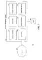
- FIG. 7illustrates a logical block diagram of a system 700 for provisioning telecommunications services in response to a request received from the access point 226 .
- FIG. 7 and the following discussionprovide a brief, general description of a suitable computing environment in which this aspect of the system can be implemented. Although not required, aspects of the system are described in the general context of computer-executable instructions, such as routines executed by a general-purpose data processing device, e.g., a server computer, wireless device, or personal computer.
- a general-purpose data processing devicee.g., a server computer, wireless device, or personal computer.
- aspects of the systemcan be practiced with other communications, data processing, or computer system configurations, including Internet appliances, handheld devices (including personal digital assistants (PDAs)), wearable computers, all manner of cellular or mobile phones, multiprocessor systems, microprocessor-based or programmable consumer electronics, set-top boxes, network PCs, mini-computers, mainframe computers, and the like.
- PDAspersonal digital assistants
- the terms “computer,” “server,” “host,” “host system,” and the likeare generally used interchangeably and refer to any of the above devices and systems, as well as any data processor.
- aspects of the systemcan be embodied in a special purpose computer or data processor that is specifically programmed, configured, or constructed to perform one or more of the computer-executable instructions explained in detail herein. While aspects of the system, such as certain functions, are described as being performed exclusively on a single device, the system can also be implemented in distributed environments where functions or modules are shared among disparate processing devices, which are linked through a communications network, such as a LAN, a WAN, or the Internet. In a distributed computing environment, program modules may be located in both local and remote memory storage devices.
- aspects of the systemmay be stored or distributed on tangible computer-readable media, including magnetically or optically readable computer discs, hard-wired or preprogrammed chips (e.g., EEPROM semiconductor chips), nanotechnology memory, biological memory, or other data storage media.
- computer-implemented instructions, data structures, screen displays, and other data under aspects of the systemmay be distributed over the Internet or over other networks (including wireless networks), on a propagated signal on a propagation medium (e.g., an electromagnetic wave(s), a sound wave, etc.) over a period of time, or they may be provided on any analog or digital network (packet switched, circuit switched, or other scheme).
- FIG. 7includes a resource management system 704 , which is configured to receive provisioning requests from the access point 226 and selectively allocate resources in response to the provisioning requests.
- the resource management system 704may be located, for example, in the network controller 242 of FIG. 2 .
- the resource management system 704is connected to a data component 706 , which stores subscriber information, such as addresses associated with individual subscribers.
- the data component 706may be, for example, the data store 246 of FIG. 2 .
- the resource management system 704includes a connection component 708 , which is configured to provide a data connection to a data network 702 , such as the IP network 204 of FIG. 2 .
- the connection component 708which may be an IP gateway, receives requests from the mobile device 206 or the access point 226 to register and provision a connection through the IP network 204 . As discussed above with reference to FIG. 4 , such requests may include the subscriber identifier (e.g., IMSI), the MAC, and the CGI REAL of the device sending the request.
- the connection component 708provides provisioning request information to an address verification component 710 , which is configured to find a geographic address associated with the request information. The system may determine the address based on identifying information, such as the subscriber identifier or the MAC.
- the resource management system 704also includes a provisioning component 712 , which is configured to selectively provision telecommunications services from the mobile device 206 or the access point 226 through the IP network 204 .
- the provisioning processmay include provisioning or rejecting a resource request based on whether a matching address was found by the address verification component 710 .
- a missing information component 714is configured to send a missing information notification to the access point 226 if the address verification component 710 did not find a matching address.
- the systemmay attempt to determine if the address determined by the address verification component 710 is out of date.
- the access point 226may include a component for determining its current geographic location (e.g., a Global Positioning System (GPS) receiver).
- GPSGlobal Positioning System
- the access point 226may provide the geographic location information in the provisioning request.
- a location comparison component 716compares the geographic location information to the geographic address stored in the database. If the locations differ by greater than a threshold amount (e.g., 0.5 miles), the system may determine that the stored address is no longer accurate and send a missing information notification.
- a threshold amounte.g., 0.5 miles
- the system 700may also include a network monitoring component 718 , which is configured to monitor a network address (e.g., an IP address) associated with the access point 226 over a period of time. If the network address changes significantly, the system may determine that the stored geographic address is no longer accurate and send a missing information notification.
- a network addresse.g., an IP address
- FIG. 8illustrates a process 800 for provisioning telecommunications services in response to a request received from the access point 226 .
- the processbegins at block 802 , where the system receives provisioning information from the access point 226 .
- the systemthen proceeds to block 804 , where it attempts to find an address associated with the received information. As discussed above, this may include looking up the subscriber identifier or MAC address in a database such as the data store 246 of FIG. 2 . Processing then proceeds to decision block 806 , where the system determines if the address was found.
- processingproceeds to decision block 808 , where the system determines if the address must be updated (based on, e.g., comparing the geographic location information to the address or detecting a change in the network address associated with the access point 226 ). If the address was not found or if the address must be updated, the system proceeds to block 812 , where it sends a missing information notification to the access point 226 . Otherwise, the system proceeds to block 810 , where it provisions the connection and notifies the access point 226 that the provisioning was successful. After notifying the access point 226 , the process exits.
- the access point 226may have two or more telephone connectors 302 .
- the access point 226provisions connections for each connector separately.
- the access point 226may contain an identifier module slot 514 for each telephone connector 302 . The access point 226 then uses each identifier module to authorize the connection separately.
- the access point 226may execute the detection and provisioning steps of the method of FIG. 6 independently for each connector.
- the subscriber identifiermay be provided to the network via a means different from a physical identifier module inserted into the access point.
- the landline phone 236may use the identifier module slot 514 to receive the identifier module and communicate the IMSI or other data stored therein to the access point 226 when the phone is connected to the access point 226 via telephone connector 302 .
- the access point 226may connect to a nearby identifier module that not only has tamper-resistant memory, but also has the capability to connect through a wired or wireless connection.
- the identifier modulemay be a Radio-Frequency Identifier (RFID) tag, or a read-only memory device with a small radio (e.g., Bluetooth or IEEE 802.11 radio), and the access point may include an appropriate reader, such as an RFID reader, Bluetooth radio, etc.
- RFIDRadio-Frequency Identifier
- the access pointmay include an appropriate reader, such as an RFID reader, Bluetooth radio, etc.
- the words “comprise,” “comprising,” and the likeare to be construed in an inclusive sense, as opposed to an exclusive or exhaustive sense; that is to say, in the sense of “including, but not limited to.”
- the terms “connected” or “coupled,” or any variant thereofmean any connection or coupling, either direct or indirect, between two or more elements; the coupling or connection between the elements can be physical, logical, or a combination thereof.
- the words “herein,” “above,” “below,” and words of similar importwhen used in this application, shall refer to this application as a whole and not to any particular portions of this application.
- words in the Detailed Description using the singular or plural numbermay also include the plural or singular number, respectively.
- the word “or,” in reference to a list of two or more items,covers all of the following interpretations of the word: any of the items in the list, all of the items in the list, and any combination of the items in the list.
Landscapes
- Engineering & Computer Science (AREA)
- Computer Networks & Wireless Communication (AREA)
- Signal Processing (AREA)
- Databases & Information Systems (AREA)
- Mobile Radio Communication Systems (AREA)
Abstract
Description
Claims (22)
Priority Applications (5)
| Application Number | Priority Date | Filing Date | Title |
|---|---|---|---|
| US12/395,593US8320344B2 (en) | 2009-02-27 | 2009-02-27 | System and method for provisioning telecommunications services between an access point and a telecommunications network and providing a missing information notification |
| CA2666472ACA2666472C (en) | 2009-02-27 | 2009-05-22 | System and method for provisioning telecommunications services between an access point and a telecommunications network and providing a missing information notification |
| CA2981031ACA2981031C (en) | 2009-02-27 | 2009-05-22 | System and method for provisioning telecommunications services between an access point and a telecommunications network and providing a missing information notification |
| PCT/US2010/025271WO2010099229A2 (en) | 2009-02-27 | 2010-02-24 | System and method for provisioning telecommunications services between an access point and a telecommunications network and providing a missing information notification |
| US13/686,619US8774148B2 (en) | 2009-02-27 | 2012-11-27 | System and method for provisioning telecommunications services between an access point and a telecommunications network and providing missing information notification |
Applications Claiming Priority (1)
| Application Number | Priority Date | Filing Date | Title |
|---|---|---|---|
| US12/395,593US8320344B2 (en) | 2009-02-27 | 2009-02-27 | System and method for provisioning telecommunications services between an access point and a telecommunications network and providing a missing information notification |
Related Child Applications (1)
| Application Number | Title | Priority Date | Filing Date |
|---|---|---|---|
| US13/686,619DivisionUS8774148B2 (en) | 2009-02-27 | 2012-11-27 | System and method for provisioning telecommunications services between an access point and a telecommunications network and providing missing information notification |
Publications (2)
| Publication Number | Publication Date |
|---|---|
| US20100220700A1 US20100220700A1 (en) | 2010-09-02 |
| US8320344B2true US8320344B2 (en) | 2012-11-27 |
Family
ID=42663738
Family Applications (2)
| Application Number | Title | Priority Date | Filing Date |
|---|---|---|---|
| US12/395,593Active2031-09-30US8320344B2 (en) | 2009-02-27 | 2009-02-27 | System and method for provisioning telecommunications services between an access point and a telecommunications network and providing a missing information notification |
| US13/686,619ActiveUS8774148B2 (en) | 2009-02-27 | 2012-11-27 | System and method for provisioning telecommunications services between an access point and a telecommunications network and providing missing information notification |
Family Applications After (1)
| Application Number | Title | Priority Date | Filing Date |
|---|---|---|---|
| US13/686,619ActiveUS8774148B2 (en) | 2009-02-27 | 2012-11-27 | System and method for provisioning telecommunications services between an access point and a telecommunications network and providing missing information notification |
Country Status (3)
| Country | Link |
|---|---|
| US (2) | US8320344B2 (en) |
| CA (2) | CA2666472C (en) |
| WO (1) | WO2010099229A2 (en) |
Cited By (8)
| Publication number | Priority date | Publication date | Assignee | Title |
|---|---|---|---|---|
| US20100014506A1 (en)* | 2008-07-17 | 2010-01-21 | Linkola Janne P | System and method for selectively provisioning telecommunications services between an access point and a telecommunications network based on landline telephone detection |
| US20100235621A1 (en)* | 2009-03-10 | 2010-09-16 | Winkler david b | Method of securely pairing devices with an access point for an ip-based wireless network |
| US20110286389A1 (en)* | 2010-04-02 | 2011-11-24 | Qualcomm Incorporated | Network registration procedures |
| US20140118463A1 (en)* | 2011-06-10 | 2014-05-01 | Thomson Licensing | Video phone system |
| US8774148B2 (en) | 2009-02-27 | 2014-07-08 | T-Mobile Usa, Inc. | System and method for provisioning telecommunications services between an access point and a telecommunications network and providing missing information notification |
| US8885635B2 (en) | 2008-07-17 | 2014-11-11 | T-Mobile Usa, Inc. | System and method for selectively provisioning telecommunications services between an access point and a telecommunications network using a subscriber identifier |
| US9301155B2 (en) | 2006-10-23 | 2016-03-29 | T-Mobile Usa, Inc. | System and method for managing access point functionality and configuration |
| US9436620B2 (en) | 2013-03-05 | 2016-09-06 | Google Inc. | Methodology for detecting problematic connections with peripheral devices |
Families Citing this family (19)
| Publication number | Priority date | Publication date | Assignee | Title |
|---|---|---|---|---|
| US8364746B2 (en) | 2005-10-21 | 2013-01-29 | T-Mobile Usa, Inc. | System and method for determining device location in an IP-based wireless telecommunications network |
| CA2620409A1 (en) | 2006-10-20 | 2008-04-20 | T-Mobile Usa, Inc. | System and method for determining a subscriber's zone information |
| US8953567B2 (en) | 2006-10-20 | 2015-02-10 | T—Mobile USA, Inc. | System and method for utilizing IP-based wireless telecommunications client location data |
| US20100010888A1 (en)* | 2008-07-14 | 2010-01-14 | Richard Maertz | Methods and systems for offering purchase incentives |
| TWI415424B (en)* | 2009-03-27 | 2013-11-11 | Mstar Semiconductor Inc | Wireless WAN to Ethernet conversion device and transmission system thereof |
| US8718592B2 (en) | 2009-05-15 | 2014-05-06 | T-Mobile Usa, Inc. | Mobile device location determination using micronetworks |
| US9077755B2 (en)* | 2009-06-10 | 2015-07-07 | Verizon Patent And Licensing Inc. | Network-based geo-location identification of an end-user device |
| US8725837B2 (en)* | 2009-06-10 | 2014-05-13 | Verizon Patent And Licensing Inc. | Content awareness caching with network-aware geo-location protocol |
| US8560410B2 (en)* | 2010-08-13 | 2013-10-15 | T-Mobile Usa, Inc. | Mapping a mobile device location to billing regions in internet protocol multimedia subsystems |
| US20120164877A1 (en)* | 2010-12-28 | 2012-06-28 | Symbol Technologies, Inc. | Method and apparatus for installing an access point over an electronic wall box |
| US9544396B2 (en)* | 2011-02-23 | 2017-01-10 | Lookout, Inc. | Remote application installation and control for a mobile device |
| US20120293465A1 (en)* | 2011-05-19 | 2012-11-22 | Ankur Nandu | Solution for location based notification of intelligent discovery application to user |
| KR101991541B1 (en)* | 2012-03-21 | 2019-06-20 | 인터디지탈 매디슨 페이튼트 홀딩스 | Apparatus and method for providing operational status for multiple communication networks |
| US9398637B2 (en)* | 2013-11-21 | 2016-07-19 | Apple Inc. | Hotspot device |
| US9859965B2 (en)* | 2014-05-27 | 2018-01-02 | Fortinet, Inc. | Telecommunication terminal |
| US10187756B1 (en) | 2017-10-19 | 2019-01-22 | 3305978 Nova Scotia Limited | Emergency location informer system |
| WO2019180509A2 (en)* | 2018-02-20 | 2019-09-26 | Saad Elghandour Amr Mohamed Elgebaly | Apparatus and method for an inter-country telecommunications system |
| JP7102311B2 (en)* | 2018-09-27 | 2022-07-19 | キヤノン株式会社 | Communication equipment, control methods for communication equipment, and programs |
| WO2023149889A1 (en)* | 2022-02-04 | 2023-08-10 | Rakuten Mobile, Inc. | Individual attribute-based transmission aspect determination |
Citations (6)
| Publication number | Priority date | Publication date | Assignee | Title |
|---|---|---|---|---|
| US6493629B1 (en)* | 2001-12-03 | 2002-12-10 | Motorola, Inc. | Method of and system for coupling location information |
| US20050083911A1 (en)* | 2003-10-21 | 2005-04-21 | 3Com Corporation, A Corporation Of The State Of Delaware | IP-based enhanced emergency services using intelligent client devices |
| US20060293024A1 (en)* | 2005-06-23 | 2006-12-28 | Lucent Technologies Inc. | Methods and apparatus for improved 911 support for VoIP service |
| US7295556B2 (en)* | 2002-03-01 | 2007-11-13 | Enterasys Networks, Inc. | Location discovery in a data network |
| US7433673B1 (en)* | 2004-12-17 | 2008-10-07 | Sprint Spectrum L.P. | Method and system for providing location information for a wireless local area network (WLAN) |
| US8160614B2 (en)* | 2005-08-05 | 2012-04-17 | Targus Information Corporation | Automated concierge system and method |
Family Cites Families (82)
| Publication number | Priority date | Publication date | Assignee | Title |
|---|---|---|---|---|
| US4998271A (en) | 1989-08-28 | 1991-03-05 | Venture Technologies, Inc. | Telephone accessory |
| US5513263A (en) | 1994-11-30 | 1996-04-30 | Motorola, Inc. | Method for establishing classes within a communication network |
| FR2771585B1 (en) | 1997-11-24 | 2000-01-28 | Nortel Matra Cellular | PRIVATE BASE STATION FOR MOBILE RADIOTELEPHONE |
| US6363421B2 (en) | 1998-05-31 | 2002-03-26 | Lucent Technologies, Inc. | Method for computer internet remote management of a telecommunication network element |
| US6985583B1 (en) | 1999-05-04 | 2006-01-10 | Rsa Security Inc. | System and method for authentication seed distribution |
| US6612489B2 (en) | 2000-01-31 | 2003-09-02 | Deliverez, Llc. | System for secured delivery of packages or other items |
| JP3864675B2 (en) | 2000-03-09 | 2007-01-10 | 株式会社日立製作所 | Common key encryption device |
| DE10019164A1 (en) | 2000-04-12 | 2001-10-18 | Mannesmann Ag | SIM lock on certain IMSI areas of a SIM card for prepaid and postpaid cards |
| US6868410B2 (en)* | 2000-06-05 | 2005-03-15 | Stephen E. Fortin | High-performance location management platform |
| US20030119490A1 (en) | 2001-02-26 | 2003-06-26 | Jahangir Mohammed | Wireless communications handset for facilitating licensed and unlicensed wireless communications, and method of operation |
| US20020147926A1 (en) | 2001-04-04 | 2002-10-10 | Pecen Mark E. | Method and apparatus for authentication using remote multiple access SIM technology |
| US7187678B2 (en) | 2001-08-13 | 2007-03-06 | At&T Labs, Inc. | Authentication for use of high speed network resources |
| US7400903B2 (en) | 2002-04-16 | 2008-07-15 | Texas Instruments Incorporated | Wireless communications system using both licensed and unlicensed frequency bands |
| US6957062B2 (en) | 2002-05-09 | 2005-10-18 | Casabyte, Inc. | Method, apparatus and article to remotely associate wireless communications devices with subscriber identities and/or proxy wireless communications devices |
| US20040078708A1 (en) | 2002-05-17 | 2004-04-22 | Chuang Li | Methods for facilitating the installation of computer devices |
| US7236799B2 (en)* | 2002-06-14 | 2007-06-26 | Cingular Wireless Ii, Llc | Apparatus and systems for providing location-based services within a wireless network |
| US7369859B2 (en)* | 2003-10-17 | 2008-05-06 | Kineto Wireless, Inc. | Method and system for determining the location of an unlicensed mobile access subscriber |
| WO2004058403A2 (en) | 2002-12-24 | 2004-07-15 | Samrat Vasisht | Method, system and device for automatically configuring a communications network |
| WO2004102941A1 (en) | 2003-03-21 | 2004-11-25 | Easylink Networks Inc. | System and process for routing telephony communications from a conventional telephone set through a data network |
| US7646777B2 (en) | 2003-07-07 | 2010-01-12 | At&T Intellectual Property I, L.P. | Communication environment switchover |
| EP1652100A4 (en) | 2003-07-09 | 2009-12-16 | Hewlett Packard Development Co | Carrier network capable of conducting remote diagnostics in a mobile handset |
| US7146153B2 (en)* | 2003-07-30 | 2006-12-05 | Sbc Knowledge Ventures, L.P. | Provisioning of wireless private access subscribers for location based services |
| KR20050017350A (en) | 2003-08-13 | 2005-02-22 | 삼성전자주식회사 | Method for generating encryption key without an input device and apparatus therefor |
| JP3951990B2 (en) | 2003-09-05 | 2007-08-01 | ブラザー工業株式会社 | Wireless station, program, and operation control method |
| CN1826825A (en) | 2003-09-10 | 2006-08-30 | 西门子公司 | Circuit configuration used as SIM card interface in GSM device |
| US7610062B2 (en) | 2003-09-15 | 2009-10-27 | At&T Mobility Ii Llc | Identification of SIM based device |
| TWI232009B (en) | 2003-10-09 | 2005-05-01 | Delta Electronics Inc | Slim phone jack |
| US7283822B2 (en) | 2003-10-17 | 2007-10-16 | Kineto Wireless, Inc. | Service access control interface for an unlicensed wireless communication system |
| US7366542B2 (en) | 2003-10-21 | 2008-04-29 | Gallitzin Allegheny Llc | Wireless security |
| TWI262011B (en) | 2003-11-06 | 2006-09-11 | Buffalo Inc | System, access point and method for setting of encryption key and authentication code |
| US7792093B2 (en) | 2003-11-15 | 2010-09-07 | At&T Mobility Ii, Llc | Method, system, and apparatus for providing wireless identification to standard telephone |
| US20050159149A1 (en) | 2003-12-27 | 2005-07-21 | Wen Kuei-Ann | Network mobile communication device |
| US20050160287A1 (en) | 2004-01-16 | 2005-07-21 | Dell Products L.P. | Method to deploy wireless network security with a wireless router |
| US20050174992A1 (en) | 2004-02-09 | 2005-08-11 | Files Ray G. | Landline telephones converted to transmit and receive cell phones telecommunication |
| US20050243809A1 (en) | 2004-04-28 | 2005-11-03 | Nec America, Inc. | System and method for configuration of Cisco's callmanager VoIP telephony |
| SE534807C2 (en) | 2004-05-14 | 2011-12-27 | Klap Worldwide Corp Trident Chambers | Mobile communication network for providing a mobile station with a fixed IP address |
| US7773579B1 (en) | 2004-06-14 | 2010-08-10 | Cisco Technology, Inc. | Multiple user telephone router |
| WO2006018047A1 (en) | 2004-08-20 | 2006-02-23 | Telecom Italia S.P.A. | Method for enrolling a user terminal in a wireless local area network |
| US7376221B1 (en) | 2004-08-20 | 2008-05-20 | Verizon Services Corp. | Methods and apparatus for multi-mode telephone |
| WO2006034399A2 (en) | 2004-09-21 | 2006-03-30 | Snapin Software Inc. | Secure software execution such as for use with a cell phone or mobile device |
| JP4735026B2 (en) | 2004-10-01 | 2011-07-27 | ソニー株式会社 | Information storage device |
| US20060121941A1 (en) | 2004-12-03 | 2006-06-08 | Shiflett Jamie C | SIM card retaining device |
| WO2006062907A1 (en) | 2004-12-06 | 2006-06-15 | Telenor Asa | Open wireless communication system for seamless call transition between licensed and unlicensed wireless networks |
| US7555783B2 (en) | 2005-01-21 | 2009-06-30 | Cisco Technology, Inc. | Wireless network credential provisioning |
| US7577458B2 (en) | 2005-01-30 | 2009-08-18 | Cisco Technology, Inc. | LCD display on wireless router |
| US7408896B2 (en) | 2005-03-02 | 2008-08-05 | Qualcomm Incorporated | Method and system for providing mobile wireless access points |
| US7983180B2 (en) | 2005-05-13 | 2011-07-19 | Cisco Technology, Inc. | Triggered announcement from a gateway |
| US7864673B2 (en) | 2005-05-24 | 2011-01-04 | At&T Mobility Ii Llc | Dynamic dual-mode service access control, location-based billing, and E911 mechanisms |
| WO2006135285A2 (en) | 2005-06-15 | 2006-12-21 | Telefonaktiebolaget Lm Ericsson (Publ) | Method and apparatus for providing a telecommunications service |
| US20060293038A1 (en) | 2005-06-23 | 2006-12-28 | Sbc Knowledge Ventures L.P. | Home cellular system |
| DE202005021930U1 (en) | 2005-08-01 | 2011-08-08 | Corning Cable Systems Llc | Fiber optic decoupling cables and pre-connected assemblies with toning parts |
| WO2007015067A2 (en) | 2005-08-01 | 2007-02-08 | Ubiquisys Limited | Local area cellular basestation |
| US20070049342A1 (en) | 2005-08-26 | 2007-03-01 | Net2Phone, Inc. | MTA-cradle personal gateway |
| US8036708B2 (en) | 2005-09-08 | 2011-10-11 | Nec Corporation | Mobile communication terminal and mobile communication method |
| FI122050B (en) | 2005-09-15 | 2011-07-29 | Network Services Finland Oy | Wireless local area network, adapter unit and facility |
| WO2007032499A1 (en) | 2005-09-16 | 2007-03-22 | National Institute Of Information And Communications Technology | Wireless communication system and wireless communication method |
| KR100749745B1 (en) | 2005-09-23 | 2007-08-17 | 엘지전자 주식회사 | Portable terminals and systems for controlling access to EVDO systems and methods |
| US20070079113A1 (en) | 2005-09-30 | 2007-04-05 | Amol Kulkarni | Automatic secure device introduction and configuration |
| US7843903B2 (en)* | 2005-11-04 | 2010-11-30 | Broadsoft M6, Llc | Methods, systems, and computer program products for emergency 911 (E911) registration assistance for subscribers using portable internet protocol (IP) communications devices |
| US20070115900A1 (en) | 2005-11-22 | 2007-05-24 | Min Liang | Method and apparatus for improved voice over internet protocol (VoIP) telephone configuration |
| US7802088B2 (en) | 2005-12-29 | 2010-09-21 | Microsoft Corporation | Ad hoc wireless network create/join user experience |
| CN101051924B (en) | 2006-04-06 | 2011-05-18 | 华为技术有限公司 | Equipment managing method for user's networks and user's network managing entity |
| EP1865656A1 (en) | 2006-06-08 | 2007-12-12 | BRITISH TELECOMMUNICATIONS public limited company | Provision of secure communications connection using third party authentication |
| US20080020773A1 (en) | 2006-07-21 | 2008-01-24 | Motorola, Inc. | Wireless communication device and method for managing the call routing for multiple services each respectively associated with a corresponding one of multiple sets of stored subscriber identity information |
| US8381304B2 (en) | 2006-07-27 | 2013-02-19 | Lenovo (Singapore) Pte. Ltd. | Apparatus and method for assuring secure disposal of a hard disk drive unit |
| CA2665854C (en) | 2006-09-21 | 2017-10-10 | T-Mobile Usa, Inc. | Wireless device registration, such as automatic registration of a wi-fi enabled device |
| US9301155B2 (en) | 2006-10-23 | 2016-03-29 | T-Mobile Usa, Inc. | System and method for managing access point functionality and configuration |
| US20080095086A1 (en) | 2006-10-23 | 2008-04-24 | Janne Linkola | Method of deploying an access point for an ip-based wireless network |
| US8189572B2 (en) | 2006-12-21 | 2012-05-29 | Verizon Patent And Licensing Inc. | Systems and methods for resetting a network device |
| US9060267B2 (en) | 2006-12-29 | 2015-06-16 | Belkin International, Inc. | Secure pairing of networked devices |
| SG178713A1 (en) | 2007-01-19 | 2012-03-29 | Roamware Inc | Method and system for providing roaming services to prepaid roamers of a home network |
| US7996541B2 (en) | 2007-06-15 | 2011-08-09 | Tekelec | Methods, systems, and computer program products for identifying a serving home subscriber server (HSS) in a communications network |
| US20090052870A1 (en) | 2007-08-22 | 2009-02-26 | Time Warner Cable Inc. | Apparatus And Method For Remote Control Of Digital Video Recorders And The Like |
| US7825820B2 (en) | 2007-09-28 | 2010-11-02 | Apple Inc. | Security using electronic devices |
| US9648493B2 (en) | 2007-11-16 | 2017-05-09 | Qualcomm Incorporated | Using identifiers to establish communication |
| US20090154701A1 (en) | 2007-12-17 | 2009-06-18 | Kosaraju Ravi K | On device number lock driven key generation for a wireless router in wireless network security systems |
| US8107881B2 (en) | 2008-02-26 | 2012-01-31 | First Data Corporation | Wireless translation device |
| US8885635B2 (en) | 2008-07-17 | 2014-11-11 | T-Mobile Usa, Inc. | System and method for selectively provisioning telecommunications services between an access point and a telecommunications network using a subscriber identifier |
| US8619545B2 (en) | 2008-07-17 | 2013-12-31 | T-Mobile Usa, Inc. | System and method for selectively provisioning telecommunications services between an access point and a telecommunications network based on landline telephone detection |
| WO2010098749A1 (en) | 2009-02-25 | 2010-09-02 | Hewlett-Packard Development Company, L.P. | Wireless device setup |
| US8320344B2 (en) | 2009-02-27 | 2012-11-27 | T-Mobile Usa, Inc. | System and method for provisioning telecommunications services between an access point and a telecommunications network and providing a missing information notification |
| US8484457B2 (en) | 2009-03-10 | 2013-07-09 | T-Mobile Usa, Inc. | Method of securely pairing devices with an access point for an IP-based wireless network |
- 2009
- 2009-02-27USUS12/395,593patent/US8320344B2/enactiveActive
- 2009-05-22CACA2666472Apatent/CA2666472C/enactiveActive
- 2009-05-22CACA2981031Apatent/CA2981031C/enactiveActive
- 2010
- 2010-02-24WOPCT/US2010/025271patent/WO2010099229A2/enactiveApplication Filing
- 2012
- 2012-11-27USUS13/686,619patent/US8774148B2/enactiveActive
Patent Citations (6)
| Publication number | Priority date | Publication date | Assignee | Title |
|---|---|---|---|---|
| US6493629B1 (en)* | 2001-12-03 | 2002-12-10 | Motorola, Inc. | Method of and system for coupling location information |
| US7295556B2 (en)* | 2002-03-01 | 2007-11-13 | Enterasys Networks, Inc. | Location discovery in a data network |
| US20050083911A1 (en)* | 2003-10-21 | 2005-04-21 | 3Com Corporation, A Corporation Of The State Of Delaware | IP-based enhanced emergency services using intelligent client devices |
| US7433673B1 (en)* | 2004-12-17 | 2008-10-07 | Sprint Spectrum L.P. | Method and system for providing location information for a wireless local area network (WLAN) |
| US20060293024A1 (en)* | 2005-06-23 | 2006-12-28 | Lucent Technologies Inc. | Methods and apparatus for improved 911 support for VoIP service |
| US8160614B2 (en)* | 2005-08-05 | 2012-04-17 | Targus Information Corporation | Automated concierge system and method |
Cited By (14)
| Publication number | Priority date | Publication date | Assignee | Title |
|---|---|---|---|---|
| US10447533B2 (en) | 2006-10-23 | 2019-10-15 | T-Mobile Usa, Inc. | System and method for managing access point functionality and configuration |
| US9843480B2 (en) | 2006-10-23 | 2017-12-12 | T-Mobile Usa, Inc. | System and method for managing access point functionality and configuration |
| US9301155B2 (en) | 2006-10-23 | 2016-03-29 | T-Mobile Usa, Inc. | System and method for managing access point functionality and configuration |
| US8885635B2 (en) | 2008-07-17 | 2014-11-11 | T-Mobile Usa, Inc. | System and method for selectively provisioning telecommunications services between an access point and a telecommunications network using a subscriber identifier |
| US9363740B2 (en) | 2008-07-17 | 2016-06-07 | T-Mobile Usa, Inc. | System and method for selectively provisioning telecommunications services between an access point and a telecommunications network using a subscriber identifier |
| US8619545B2 (en) | 2008-07-17 | 2013-12-31 | T-Mobile Usa, Inc. | System and method for selectively provisioning telecommunications services between an access point and a telecommunications network based on landline telephone detection |
| US20100014506A1 (en)* | 2008-07-17 | 2010-01-21 | Linkola Janne P | System and method for selectively provisioning telecommunications services between an access point and a telecommunications network based on landline telephone detection |
| US8774148B2 (en) | 2009-02-27 | 2014-07-08 | T-Mobile Usa, Inc. | System and method for provisioning telecommunications services between an access point and a telecommunications network and providing missing information notification |
| US8484457B2 (en) | 2009-03-10 | 2013-07-09 | T-Mobile Usa, Inc. | Method of securely pairing devices with an access point for an IP-based wireless network |
| US20100235621A1 (en)* | 2009-03-10 | 2010-09-16 | Winkler david b | Method of securely pairing devices with an access point for an ip-based wireless network |
| US8995318B2 (en)* | 2010-04-02 | 2015-03-31 | Qualcomm Incorporated | Network registration procedures |
| US20110286389A1 (en)* | 2010-04-02 | 2011-11-24 | Qualcomm Incorporated | Network registration procedures |
| US20140118463A1 (en)* | 2011-06-10 | 2014-05-01 | Thomson Licensing | Video phone system |
| US9436620B2 (en) | 2013-03-05 | 2016-09-06 | Google Inc. | Methodology for detecting problematic connections with peripheral devices |
Also Published As
| Publication number | Publication date |
|---|---|
| CA2666472A1 (en) | 2010-08-27 |
| US20130083785A1 (en) | 2013-04-04 |
| US8774148B2 (en) | 2014-07-08 |
| CA2981031A1 (en) | 2010-08-27 |
| CA2981031C (en) | 2019-03-19 |
| WO2010099229A3 (en) | 2010-12-29 |
| US20100220700A1 (en) | 2010-09-02 |
| WO2010099229A2 (en) | 2010-09-02 |
| CA2666472C (en) | 2017-11-07 |
Similar Documents
| Publication | Publication Date | Title |
|---|---|---|
| US8320344B2 (en) | System and method for provisioning telecommunications services between an access point and a telecommunications network and providing a missing information notification | |
| US8953620B2 (en) | System and method for selectively provisioning telecommunications services between an access point and a telecommunications network using a subscriber identifier | |
| US9363740B2 (en) | System and method for selectively provisioning telecommunications services between an access point and a telecommunications network using a subscriber identifier | |
| US10419875B2 (en) | System and method for determining a subscriber's zone information | |
| US8189549B2 (en) | System and method for indicating a subscriber's zone within converged telecommunications networks | |
| CA2665875C (en) | Authorizing access to telecommunications networks for mobile devices, such as mobile devices accessing networks via non-traditional entry points | |
| CA2619397C (en) | System and method for authorizing access to an ip-based wireless telecommunications service | |
| US8619545B2 (en) | System and method for selectively provisioning telecommunications services between an access point and a telecommunications network based on landline telephone detection | |
| US12213046B2 (en) | Method and system for supporting emergency voice services over wireless local area network (WLAN) using dynamic SSID deployment | |
| WO2010102149A2 (en) | Authorizing access to telecommunications networks for mobile devices, such as mobile devices accessing networks via non-traditional entry points | |
| WO2010102242A2 (en) | System and method for indicating a subscriber's zone within converged telecommunications networks | |
| US20240292184A1 (en) | Method and system for supporting non-emergency community services over wireless local area network (WLAN) |
Legal Events
| Date | Code | Title | Description |
|---|---|---|---|
| AS | Assignment | Owner name:T-MOBILE USA, INC., WASHINGTON Free format text:ASSIGNMENT OF ASSIGNORS INTEREST;ASSIGNORS:HODROJ, SAMIR;HASSAN, OMAR;SIGNING DATES FROM 20090224 TO 20090225;REEL/FRAME:024138/0093 | |
| STCF | Information on status: patent grant | Free format text:PATENTED CASE | |
| AS | Assignment | Owner name:DEUTSCHE BANK AG NEW YORK BRANCH, AS ADMINISTRATIVE AGENT, NEW YORK Free format text:SECURITY AGREEMENT;ASSIGNORS:T-MOBILE USA, INC.;METROPCS COMMUNICATIONS, INC.;T-MOBILE SUBSIDIARY IV CORPORATION;REEL/FRAME:037125/0885 Effective date:20151109 Owner name:DEUTSCHE BANK AG NEW YORK BRANCH, AS ADMINISTRATIV Free format text:SECURITY AGREEMENT;ASSIGNORS:T-MOBILE USA, INC.;METROPCS COMMUNICATIONS, INC.;T-MOBILE SUBSIDIARY IV CORPORATION;REEL/FRAME:037125/0885 Effective date:20151109 | |
| FPAY | Fee payment | Year of fee payment:4 | |
| AS | Assignment | Owner name:DEUTSCHE TELEKOM AG, GERMANY Free format text:INTELLECTUAL PROPERTY SECURITY AGREEMENT;ASSIGNOR:T-MOBILE USA, INC.;REEL/FRAME:041225/0910 Effective date:20161229 | |
| AS | Assignment | Owner name:METROPCS COMMUNICATIONS, INC., WASHINGTON Free format text:RELEASE BY SECURED PARTY;ASSIGNOR:DEUTSCHE BANK AG NEW YORK BRANCH;REEL/FRAME:052969/0314 Effective date:20200401 Owner name:LAYER3 TV, INC., WASHINGTON Free format text:RELEASE BY SECURED PARTY;ASSIGNOR:DEUTSCHE BANK AG NEW YORK BRANCH;REEL/FRAME:052969/0314 Effective date:20200401 Owner name:PUSHSPRING, INC., WASHINGTON Free format text:RELEASE BY SECURED PARTY;ASSIGNOR:DEUTSCHE BANK AG NEW YORK BRANCH;REEL/FRAME:052969/0314 Effective date:20200401 Owner name:T-MOBILE USA, INC., WASHINGTON Free format text:RELEASE BY SECURED PARTY;ASSIGNOR:DEUTSCHE BANK AG NEW YORK BRANCH;REEL/FRAME:052969/0314 Effective date:20200401 Owner name:T-MOBILE USA, INC., WASHINGTON Free format text:RELEASE BY SECURED PARTY;ASSIGNOR:DEUTSCHE TELEKOM AG;REEL/FRAME:052969/0381 Effective date:20200401 Owner name:T-MOBILE SUBSIDIARY IV CORPORATION, WASHINGTON Free format text:RELEASE BY SECURED PARTY;ASSIGNOR:DEUTSCHE BANK AG NEW YORK BRANCH;REEL/FRAME:052969/0314 Effective date:20200401 Owner name:METROPCS WIRELESS, INC., WASHINGTON Free format text:RELEASE BY SECURED PARTY;ASSIGNOR:DEUTSCHE BANK AG NEW YORK BRANCH;REEL/FRAME:052969/0314 Effective date:20200401 Owner name:IBSV LLC, WASHINGTON Free format text:RELEASE BY SECURED PARTY;ASSIGNOR:DEUTSCHE BANK AG NEW YORK BRANCH;REEL/FRAME:052969/0314 Effective date:20200401 Owner name:IBSV LLC, WASHINGTON Free format text:RELEASE BY SECURED PARTY;ASSIGNOR:DEUTSCHE TELEKOM AG;REEL/FRAME:052969/0381 Effective date:20200401 | |
| AS | Assignment | Owner name:DEUTSCHE BANK TRUST COMPANY AMERICAS, NEW YORK Free format text:SECURITY AGREEMENT;ASSIGNORS:T-MOBILE USA, INC.;ISBV LLC;T-MOBILE CENTRAL LLC;AND OTHERS;REEL/FRAME:053182/0001 Effective date:20200401 | |
| MAFP | Maintenance fee payment | Free format text:PAYMENT OF MAINTENANCE FEE, 8TH YEAR, LARGE ENTITY (ORIGINAL EVENT CODE: M1552); ENTITY STATUS OF PATENT OWNER: LARGE ENTITY Year of fee payment:8 | |
| AS | Assignment | Owner name:SPRINT SPECTRUM LLC, KANSAS Free format text:RELEASE BY SECURED PARTY;ASSIGNOR:DEUTSCHE BANK TRUST COMPANY AMERICAS;REEL/FRAME:062595/0001 Effective date:20220822 Owner name:SPRINT INTERNATIONAL INCORPORATED, KANSAS Free format text:RELEASE BY SECURED PARTY;ASSIGNOR:DEUTSCHE BANK TRUST COMPANY AMERICAS;REEL/FRAME:062595/0001 Effective date:20220822 Owner name:SPRINT COMMUNICATIONS COMPANY L.P., KANSAS Free format text:RELEASE BY SECURED PARTY;ASSIGNOR:DEUTSCHE BANK TRUST COMPANY AMERICAS;REEL/FRAME:062595/0001 Effective date:20220822 Owner name:SPRINTCOM LLC, KANSAS Free format text:RELEASE BY SECURED PARTY;ASSIGNOR:DEUTSCHE BANK TRUST COMPANY AMERICAS;REEL/FRAME:062595/0001 Effective date:20220822 Owner name:CLEARWIRE IP HOLDINGS LLC, KANSAS Free format text:RELEASE BY SECURED PARTY;ASSIGNOR:DEUTSCHE BANK TRUST COMPANY AMERICAS;REEL/FRAME:062595/0001 Effective date:20220822 Owner name:CLEARWIRE COMMUNICATIONS LLC, KANSAS Free format text:RELEASE BY SECURED PARTY;ASSIGNOR:DEUTSCHE BANK TRUST COMPANY AMERICAS;REEL/FRAME:062595/0001 Effective date:20220822 Owner name:BOOST WORLDWIDE, LLC, KANSAS Free format text:RELEASE BY SECURED PARTY;ASSIGNOR:DEUTSCHE BANK TRUST COMPANY AMERICAS;REEL/FRAME:062595/0001 Effective date:20220822 Owner name:ASSURANCE WIRELESS USA, L.P., KANSAS Free format text:RELEASE BY SECURED PARTY;ASSIGNOR:DEUTSCHE BANK TRUST COMPANY AMERICAS;REEL/FRAME:062595/0001 Effective date:20220822 Owner name:T-MOBILE USA, INC., WASHINGTON Free format text:RELEASE BY SECURED PARTY;ASSIGNOR:DEUTSCHE BANK TRUST COMPANY AMERICAS;REEL/FRAME:062595/0001 Effective date:20220822 Owner name:T-MOBILE CENTRAL LLC, WASHINGTON Free format text:RELEASE BY SECURED PARTY;ASSIGNOR:DEUTSCHE BANK TRUST COMPANY AMERICAS;REEL/FRAME:062595/0001 Effective date:20220822 Owner name:PUSHSPRING, LLC, WASHINGTON Free format text:RELEASE BY SECURED PARTY;ASSIGNOR:DEUTSCHE BANK TRUST COMPANY AMERICAS;REEL/FRAME:062595/0001 Effective date:20220822 Owner name:LAYER3 TV, LLC, WASHINGTON Free format text:RELEASE BY SECURED PARTY;ASSIGNOR:DEUTSCHE BANK TRUST COMPANY AMERICAS;REEL/FRAME:062595/0001 Effective date:20220822 Owner name:IBSV LLC, WASHINGTON Free format text:RELEASE BY SECURED PARTY;ASSIGNOR:DEUTSCHE BANK TRUST COMPANY AMERICAS;REEL/FRAME:062595/0001 Effective date:20220822 | |
| MAFP | Maintenance fee payment | Free format text:PAYMENT OF MAINTENANCE FEE, 12TH YEAR, LARGE ENTITY (ORIGINAL EVENT CODE: M1553); ENTITY STATUS OF PATENT OWNER: LARGE ENTITY Year of fee payment:12 |