US8319993B2 - Methods for operating user interfaces of a device controllable at a plurality of access points - Google Patents
Methods for operating user interfaces of a device controllable at a plurality of access pointsDownload PDFInfo
- Publication number
- US8319993B2 US8319993B2US12/011,133US1113308AUS8319993B2US 8319993 B2US8319993 B2US 8319993B2US 1113308 AUS1113308 AUS 1113308AUS 8319993 B2US8319993 B2US 8319993B2
- Authority
- US
- United States
- Prior art keywords
- job
- context
- virtual
- contexts
- state
- Prior art date
- Legal status (The legal status is an assumption and is not a legal conclusion. Google has not performed a legal analysis and makes no representation as to the accuracy of the status listed.)
- Expired - Fee Related, expires
Links
Images


Classifications
- H—ELECTRICITY
- H04—ELECTRIC COMMUNICATION TECHNIQUE
- H04L—TRANSMISSION OF DIGITAL INFORMATION, e.g. TELEGRAPHIC COMMUNICATION
- H04L41/00—Arrangements for maintenance, administration or management of data switching networks, e.g. of packet switching networks
- H04L41/22—Arrangements for maintenance, administration or management of data switching networks, e.g. of packet switching networks comprising specially adapted graphical user interfaces [GUI]
- G—PHYSICS
- G03—PHOTOGRAPHY; CINEMATOGRAPHY; ANALOGOUS TECHNIQUES USING WAVES OTHER THAN OPTICAL WAVES; ELECTROGRAPHY; HOLOGRAPHY
- G03G—ELECTROGRAPHY; ELECTROPHOTOGRAPHY; MAGNETOGRAPHY
- G03G15/00—Apparatus for electrographic processes using a charge pattern
- G03G15/50—Machine control of apparatus for electrographic processes using a charge pattern, e.g. regulating differents parts of the machine, multimode copiers, microprocessor control
- G03G15/5016—User-machine interface; Display panels; Control console
- G03G15/502—User-machine interface; Display panels; Control console relating to the structure of the control menu, e.g. pop-up menus, help screens
- G—PHYSICS
- G03—PHOTOGRAPHY; CINEMATOGRAPHY; ANALOGOUS TECHNIQUES USING WAVES OTHER THAN OPTICAL WAVES; ELECTROGRAPHY; HOLOGRAPHY
- G03G—ELECTROGRAPHY; ELECTROPHOTOGRAPHY; MAGNETOGRAPHY
- G03G15/00—Apparatus for electrographic processes using a charge pattern
- G03G15/50—Machine control of apparatus for electrographic processes using a charge pattern, e.g. regulating differents parts of the machine, multimode copiers, microprocessor control
- G03G15/5075—Remote control machines, e.g. by a host
- G—PHYSICS
- G06—COMPUTING OR CALCULATING; COUNTING
- G06F—ELECTRIC DIGITAL DATA PROCESSING
- G06F3/00—Input arrangements for transferring data to be processed into a form capable of being handled by the computer; Output arrangements for transferring data from processing unit to output unit, e.g. interface arrangements
- G06F3/12—Digital output to print unit, e.g. line printer, chain printer
- G06F3/1201—Dedicated interfaces to print systems
- G06F3/1202—Dedicated interfaces to print systems specifically adapted to achieve a particular effect
- G06F3/1211—Improving printing performance
- G—PHYSICS
- G06—COMPUTING OR CALCULATING; COUNTING
- G06F—ELECTRIC DIGITAL DATA PROCESSING
- G06F3/00—Input arrangements for transferring data to be processed into a form capable of being handled by the computer; Output arrangements for transferring data from processing unit to output unit, e.g. interface arrangements
- G06F3/12—Digital output to print unit, e.g. line printer, chain printer
- G06F3/1201—Dedicated interfaces to print systems
- G06F3/1223—Dedicated interfaces to print systems specifically adapted to use a particular technique
- G06F3/1237—Print job management
- G—PHYSICS
- G03—PHOTOGRAPHY; CINEMATOGRAPHY; ANALOGOUS TECHNIQUES USING WAVES OTHER THAN OPTICAL WAVES; ELECTROGRAPHY; HOLOGRAPHY
- G03G—ELECTROGRAPHY; ELECTROPHOTOGRAPHY; MAGNETOGRAPHY
- G03G2215/00—Apparatus for electrophotographic processes
- G03G2215/00025—Machine control, e.g. regulating different parts of the machine
- G03G2215/00109—Remote control of apparatus, e.g. by a host
Definitions
- Multifunction peripheral devicesare capable of multiple functions such as copying, scanning and printing. These device may receive jobs such as electronic print jobs or files from a connected host device such a PC, or over a network such as a local area network (LAN) or wide area network (WAN), and from user activation of a local front panel. If multiple users attempt to simultaneously operate an MFP from different locations, difficulties can arise.
- jobssuch as electronic print jobs or files from a connected host device such a PC, or over a network such as a local area network (LAN) or wide area network (WAN), and from user activation of a local front panel.
- LANlocal area network
- WANwide area network
- FIG. 1schematically depicts an exemplary operating environment for an exemplary embodiment of a control method.
- FIG. 2is a schematic diagram illustrating an exemplary embodiment of virtual user interfaces for an MFP device.
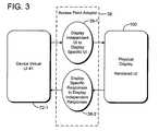
- FIG. 3is a simplified diagrammatic view illustrating an exemplary technique for associating a virtual UI with a physical display as illustrated in FIG. 3 .
- FIG. 4is a schematic diagram illustrating an exemplary technique for associating a virtual UI with one or more physical display devices.
- FIG. 5diagrammatically illustrates an exemplary embodiment depicting possible state progressions through which two job contexts may proceed.
- FIG. 6shows exemplary state progressions through which two virtual UIs for a single job context may go through, for an exemplary embodiment.
- An exemplary embodimentmay provide a method for operating the user interfaces (UIs) of a device such as an MFP device while the device is under simultaneous user operations from different interfaces and access points.
- UIsuser interfaces
- FIG. 1An exemplary operating environment is illustrated in FIG. 1 , and includes one or more MFP devices. Each MFP has the capability to project a copy of its UI to a remote access point.
- HTML 4.01HTML 4.01 Specification, W3C Recommendation, 24 Dec. 1999
- W3C Recommendation24 Dec. 1999
- each MFPmay operate in multiple simultaneous job contexts, such as one for printing and another for device administration.
- This multi-job simultaneous handlingis done through a job context switch (e.g., time sharing).
- the job context switchmay also be responsible for handling resource conflicts between job contexts (e.g., use of the scanner).
- Each job contexthas associated with it an instance of the device's UI.
- Each UI instanceis a derivative of one of the device's native UI states. That is, the device creates a common virtual UI per interface access, independent of the access point.
- An access point adaptorconverts the virtual UI into a physical UI instance.
- Some job contextsmay have shared UIs. For example, if two users are both viewing the device's job queue, the virtual UI for each user would be the same device UI state. In other cases, the job contexts may have different UIs. For example, if two users are entering job parameters, the virtual UI for each user may be a different instance derived from the same initial device UI state.
- each virtual UI associated with a job menumay be updated with an offline indicator.
- An exemplary operating environment 20is schematically illustrated in FIG. 1 , and includes one or more MFPs 30 and 40 , devices A and B.
- the MFPsmay perform one or more imaging related functions, such as printing, copying, faxing, scanning, document filing, publishing to the web, format conversion, and audio/visual (A/V) recording/displaying.
- imaging related functionssuch as printing, copying, faxing, scanning, document filing, publishing to the web, format conversion, and audio/visual (A/V) recording/displaying.
- MFP 30has a controller 32 , a local access point 34 which may be a front panel and corresponding local or native UI, a UI switch controller 36 and an access point adaptor 38 .
- the MFP 30is communicatively connected to at least one remote access point 52 , in this example provided by host 50 .
- MFP 40similarly has a controller 42 , a local access point 44 such as a front panel and corresponding local or native UI, a UI switch controller 48 , and an access point adaptor 48 .
- the MFP 40is communicatively connected to at least one remote access point 56 , in this example provided by host 50 .
- the device controller 32 and 42may be implemented by a microcomputer or an ASIC, and may include a digital memory.
- the UI switch controller 36 and 46may be implemented as a firmware module in the MFP.
- the host 50may be connected to the MFPs by a local area network, a wide area network, by internet connections, or by other connection technologies.
- the MFP devices, the host 50 and remote access pointsmay be communicatively coupled, such as by TCP/IP, Apple Talk, IEEE 1284 Parallel Port, IrDA, Bluetooth, WiFi, other wireless protocols, and local ports (e.g., serial, USB).
- the host 50may be a personal computer or a server, for example, and includes a device administrator utility program 54 , which may be configured to control each MFP 30 and 40 .
- each MFP devicecan project a replica of the MFP's front panel UI, such as through a web browser.
- the device A UIis projected through the remote access point 52 to provide a remote replica of the UI as rendered device A UI 36 -A.
- the device B UIis projected through the remote access point 56 to provide a remote replica of the UI as rendered device B UI 46 -A.
- Each MFPmay be operated in the same manner from the remote UI 36 -A and 46 -A, respectively, as with the local UI 36 and 46 , respectively. Changes made on the remote UI are reflected back on the local UI and vice-versa.
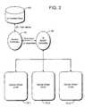
- FIG. 2is a simplified schematic illustration of an exemplary embodiment showing an MFP's user interface rendered as a plurality of virtual UIs.
- the MFP UIis defined in a display independent manner. For example, it may be defined in HTML, XHTMUCSS, WML or Proprietary XML schema.
- All the MFP's UI statesare represented (either statically or dynamically) in a device independent manner.
- One UI staterepresents the root UI state, from which all other UI states are derived from.
- a root UI statemay be anything, such as a welcome screen with an enter button, a top level job choice menu, or a user login.
- the root UI stateis the first UI presented to the user when the device is first activated.
- the MFPmay perform multiple simultaneous jobs which are independently initiated.
- Each simultaneous jobhas an associated sequence of UI states 60 ( FIG. 2 ), which may be a predetermined or dynamically determined sequence.
- Each simultaneous jobhas a job context.
- the job contextstores information to suspend and resume the job state.
- One of the items storedis the current UI state associated with the job, i.e. the UI context state 60 ( FIG. 2 ).
- the current UI stateis stored in a device independent manner (e.g., XHTMUCSS) in the device controller 32 .
- the MFPmay be performing two print jobs 1 and 2 and a scan job 3.
- the MFP controllertime slices operations between the jobs as to avoid resource conflicts and achieve optimal output performance.
- the MFPmay do the following time slices:
- One or more of the above operations, when not in resource conflict,may also be performed in parallel.
- the current job context 60is loaded into the device controller 32 of exemplary device 30 ( FIG. 1 ), which starts performing the next task(s) in the job. Additionally, the current UI state is loaded into the virtual UI associated with the job and sent to the UI switch controller 38 of the exemplary MFP 30 . As the device controller 32 performs actions, the current UI state is updated and loaded into the virtual UI associated with the job, in this case virtual UIs 72 - 1 , 72 - 2 and 72 - 3 ( FIG. 2 ).
- a virtual UImay be associated with a physical display as illustrated in FIG. 3 , in which exemplary device virtual UI 72 - 1 is associated with a physical display device 100 .
- an access point adaptor 38converts the virtual UI to a display specific UI which is provided to physical display 100 by an operation indicated as 38 - 1 .
- the access point adaptor 38updates the corresponding changes in the physically rendered UI.
- the access point adaptoris a process that maps between the abstract representation of a virtual UI to a physical representation, and vice versa.
- Such processesare known in the art; one example is XUL, a user interface language (http://www.mozilla.org/projects/xul/) for generically describing a UI, and transmitting it to another device, which then renders it specific to its interface.
- XULa user interface language (http://www.mozilla.org/projects/xul/) for generically describing a UI, and transmitting it to another device, which then renders it specific to its interface.
- Inputsmay also be received through the physically rendered UI 102 , which are then mapped back to the access point adaptor 38 , converted to the display independent format by the operation 38 - 2 ( FIG. 3 ) and passed back to the device controller such as controller 32 ( FIG. 1 ).
- the device controllerin response may effect a change in the execution of the job and/or update the current UI state.
- Switching out a job contextin this exemplary embodiment relates to parallel job processing, i.e., if the MFP device is doing two jobs at the same time, the device may do chunks of one, then the other and so forth. Switching out a job may also apply to suspending and resuming a job.
- each virtual UImay be associated with one or more physical display devices.
- the MFP devicemay have three virtual UIs 72 - 1 , 72 - 2 and 72 - 3 corresponding to the earlier described three simultaneous jobs.
- the first job context(print job #1) may be associated with a remote access point 90 , such as a web browser on a host PC.
- the useroperates the web browser to attach to the virtual UI 72 - 1 . This may be done by entering a unique URL associated with the job context (e.g., mydevice/job1).
- the current UI state associated with the virtual UIis then converted by the access point adaptor 38 into a format that can be rendered by the web browser.
- the second job contextmay be associated with another remote access point, such as a remote application interface (RAI) 92 ( FIG. 4 ).
- a remote application interfaceRAI
- an application remote from the MFPe.g., a Sharp OSA (Open System Architecture) application, a printer driver, etc.
- the user interface of the remote applicationmay be imported and its responses exported to/from the MFP.
- the access point adaptormay be embedded in the remote application, or otherwise be upstream from the remote application, i.e. between the remote application and the MFP device.
- the access point adaptormay be implemented as a firmware module or software module within the MFP.
- the access point adaptormay be implemented in a host device such as host computer 50 .
- the third job contextmay be associated with both a local and remote access point 94 A, 94 B.
- the virtual UI 72 - 3is mapped via the access point adaptor 38 to both the physical displays associated with the local and remote access points.
- Both manifested UIswould be replicas of the other, within display capabilities. Inputs entered through one manifested UI would affect the same change as if entered via the other manifested UI. Any change in UI state is then propagated to each manifested UI.
- the usermay initiate a scan-to-application job from a host PC.
- the applicationmay have a remote application interface, such as remote access 52 or 56 ( FIG. 1 ), which allows the application to display a sequence of UI states from the MFP associated with the scan job.
- the usermight set scan settings at the application and the target send location.
- the usermay then physically walk up to the MFP and enable the job context associated with their scan job through the front panel, such as by selecting from a job list or entering a PIN, job id or password.
- the current UI state of the virtual UI stored in the job contextis then loaded and converted for rendering on the local user interface (e.g., LCD touch panel).
- two or more virtual UIsmay be connected as a single logical UI, such as the shared UI context state 60 ( FIG. 2 ).
- a single logical UIis associated with a job context which may have one or more virtual UI interfaces (e.g., local and remote).
- a logical UIhas a single virtual UI.
- two usersmay be using the MFP simultaneously, such as printing a print job.
- Each userhas a job context and an associated virtual UI (V-UI) connected to a display means, i.e. a physically rendered view, e.g. a browser window, direct print application window on a host PC, etc.
- V-UIvirtual UI
- FIG. 5diagrammatically illustrates possible state progressions through which the two job contexts may go in an exemplary embodiment.
- both V-UIsare initialized to the default UI state of the MFP device, indicated as default state 102 passed through a UI switch as default states 104 , 106 to initialize V-UIs # 1 and # 2 to the default state.
- the first usergenerates a first activity 108 (e.g., a print job submission).
- a UI switchpasses the first UI activity to the first job context as 110 .
- the job contextmay then update the current UI state (as UI update 112 ).
- the UI switchthen updates 114 the V-UI for the first activity according to the current UI state.
- the second user at V-UI # 2generates a second activity 116 (e.g., a print job submission).
- the UI switchpasses the second UI activity to the second job context 118 .
- the job contextmay then update the current UI state 120 .
- the UI switchthen updates the V-UI for the second activity according to the current UI state.
- a logical UIhas multiple virtual UIs.
- a remote operator technicianmay assist a walkup user to an MFP device. Both the walkup user and the remote operator have the same job context, but with different associated V-UIs.
- the walkup userhas a V-UI # 1 connected to the front panel, while the remote operator has a V-UI # 2 connected to a display means (e.g., web browser) on a host PC.
- the remote operator's UIcan be considered a clone of the walkup user's UI.
- FIG. 6shows possible state progressions the two V-UIs for a single job context may go through, for an exemplary embodiment.
- both V-UIsV-UI # 1 and V-UI # 2
- V-UI # 1 and V-UI # 2are initialized ( 204 , 206 ) to the default UI state 202 of the MFP device.
- the walkup usergenerates a first activity 208 (e.g., scan-to-desktop).
- a UI switchpasses the first UI activity to the single job context as 210 .
- the job contextmay then update the current UI state as 212 , as a result of performing actions associated with the first UI activity.
- the UI switchthen updates the V-UIs for both the walkup user and remote operator for the current UI state ( 214 , 216 ).
- the remote operatormay then generate a second activity 216 (e.g., correcting the user's input).
- a UI switchpasses the second UI activity to the single job context as 218 .
- the job contextmay then update the current UI state 220 as a result of performing actions associated with the second UI activity.
- the UI switchthen updates the V-UIs for both the walkup user and remote operator for the current UI state ( 222 and 224 ).
- an exemplary embodimentmay be practiced on an imaging related device
- other applicationsinclude other multi-user peripheral devices, such as a set-top box, a computer, a communication switch, and a gaming device.
Landscapes
- Engineering & Computer Science (AREA)
- Human Computer Interaction (AREA)
- Physics & Mathematics (AREA)
- General Physics & Mathematics (AREA)
- Theoretical Computer Science (AREA)
- General Engineering & Computer Science (AREA)
- Microelectronics & Electronic Packaging (AREA)
- Computer Networks & Wireless Communication (AREA)
- Signal Processing (AREA)
- Facsimiles In General (AREA)
- Accessory Devices And Overall Control Thereof (AREA)
Abstract
Description
| Time Slice | Job | Activity | ||
| 0 | 1 | |||
| 1 | 2 | |||
| 2 | 3 | |||
| 3 | 1 | Ripping (raster image processing) | ||
| 4 | 3 | Scanning | ||
| 5 | 2 | Outputting | ||
| 6 | 1 | Ripping | ||
| 7 | 2 | Outputting | ||
| 8 | 3 | Sending | ||
Claims (17)
Priority Applications (2)
| Application Number | Priority Date | Filing Date | Title |
|---|---|---|---|
| US12/011,133US8319993B2 (en) | 2008-01-24 | 2008-01-24 | Methods for operating user interfaces of a device controllable at a plurality of access points |
| JP2008321232AJP4796617B2 (en) | 2008-01-24 | 2008-12-17 | How to operate the user interface of a device that can be controlled from multiple access points |
Applications Claiming Priority (1)
| Application Number | Priority Date | Filing Date | Title |
|---|---|---|---|
| US12/011,133US8319993B2 (en) | 2008-01-24 | 2008-01-24 | Methods for operating user interfaces of a device controllable at a plurality of access points |
Publications (2)
| Publication Number | Publication Date |
|---|---|
| US20090190157A1 US20090190157A1 (en) | 2009-07-30 |
| US8319993B2true US8319993B2 (en) | 2012-11-27 |
Family
ID=40898900
Family Applications (1)
| Application Number | Title | Priority Date | Filing Date |
|---|---|---|---|
| US12/011,133Expired - Fee RelatedUS8319993B2 (en) | 2008-01-24 | 2008-01-24 | Methods for operating user interfaces of a device controllable at a plurality of access points |
Country Status (2)
| Country | Link |
|---|---|
| US (1) | US8319993B2 (en) |
| JP (1) | JP4796617B2 (en) |
Families Citing this family (6)
| Publication number | Priority date | Publication date | Assignee | Title |
|---|---|---|---|---|
| US8289901B2 (en)* | 2009-03-17 | 2012-10-16 | Cisco Technology, Inc. | Pinning and cascading avoidance in dynamic channel assignment for wireless LANS |
| JP5240263B2 (en) | 2010-09-15 | 2013-07-17 | コニカミノルタビジネステクノロジーズ株式会社 | Image forming apparatus, display control method, and display control program |
| US9183536B1 (en) | 2010-10-22 | 2015-11-10 | United Services Automobile Association (Usaa) | Service representative and remote location document communication |
| TWI451272B (en)* | 2012-05-02 | 2014-09-01 | Arcadyan Technology Corp | Universal driving method and system for peripherals |
| JP6012268B2 (en)* | 2012-06-08 | 2016-10-25 | キヤノン株式会社 | Image processing apparatus, image processing system, control method, and program |
| US11960779B1 (en)* | 2023-06-08 | 2024-04-16 | Vmware, Inc. | Document printing in a virtualized computing environment |
Citations (27)
| Publication number | Priority date | Publication date | Assignee | Title |
|---|---|---|---|---|
| US4982344A (en)* | 1988-05-18 | 1991-01-01 | Xerox Corporation | Accelerating link creation |
| US5333286A (en) | 1989-12-13 | 1994-07-26 | Joseph Weinberger | Two way copier monitoring system |
| JPH0773011A (en) | 1993-09-06 | 1995-03-17 | Hitachi Eng Co Ltd | Graphic drawing device |
| JPH08234945A (en) | 1995-02-28 | 1996-09-13 | Nec Niigata Ltd | Printer capable of setting menu by host computer |
| US5699494A (en) | 1995-02-24 | 1997-12-16 | Lexmark International, Inc. | Remote replication of printer operator panel |
| US5937150A (en) | 1997-02-10 | 1999-08-10 | Toshiba America Information Systems, Inc. | LCD panel controlled by two process elements |
| JP2002073320A (en) | 2000-08-30 | 2002-03-12 | Digital Electronics Corp | Display screen generation device for programmed display device |
| US20020122203A1 (en) | 2001-03-02 | 2002-09-05 | Hiroshi Matsuda | Image processing device, information processing method, and control program |
| EP1293884A2 (en) | 2001-09-14 | 2003-03-19 | Canon Kabushiki Kaisha | Printing control method and apparatus |
| US20030053105A1 (en)* | 2001-09-14 | 2003-03-20 | Hidekazu Morooka | Print control method, print control apparatus, print control program which can be executed by information processing apparatus, and memory medium in which computer-readable program has been stored |
| US20040061729A1 (en) | 2002-09-30 | 2004-04-01 | Brett Green | System and method for a dynamically modifiable driver interface |
| US20040260790A1 (en) | 2000-12-21 | 2004-12-23 | Ge Medical System Global Technology Company, Llc | Method and apparatus for remote or collaborative control of an imaging system |
| US20050022210A1 (en)* | 1999-06-11 | 2005-01-27 | Microsoft Corporation | Synchronization of controlled device state using state table and eventing in data-driven remote device control model |
| US20050162675A1 (en) | 2004-01-23 | 2005-07-28 | Sharp Laboratories Of America, Inc. | Method and apparatus for embedded driver download using raw imaging protocol |
| US20050259277A1 (en) | 2004-05-18 | 2005-11-24 | Ferlitsch Andrew R | System and method for combining at a single location selection of image finishing operations of multiple devices |
| US20050283735A1 (en) | 2004-06-17 | 2005-12-22 | Sharp Laboratories Of America, Inc. | Adaptive universal symbol driver interface |
| US20060026600A1 (en)* | 2004-07-27 | 2006-02-02 | Brother Kogyo Kabushiki Kaisha | Selecting setting options method, device and computer program product |
| US20060039012A1 (en) | 2004-08-19 | 2006-02-23 | Sharp Laboratories Of America, Inc. | Combined host and imaging device menu interface |
| US20060098221A1 (en) | 2004-11-08 | 2006-05-11 | Sharp Laboratories Of America, Inc. | Systems and methods for providing a configurable user interface on an imaging device |
| US20060129746A1 (en) | 2004-12-14 | 2006-06-15 | Ithink, Inc. | Method and graphic interface for storing, moving, sending or printing electronic data to two or more locations, in two or more formats with a single save function |
| US20060158674A1 (en) | 2005-01-14 | 2006-07-20 | Yoshihiro Mizoguchi | Printer driver, information processing device including the same, print control device, and print data generating method |
| US20070028182A1 (en) | 2005-07-27 | 2007-02-01 | Samsung Electronics Co., Ltd. | Device and method for displaying a user interface window |
| JP2007042065A (en) | 2005-06-28 | 2007-02-15 | Canon Inc | Application management system, application management method and program |
| US20070288857A1 (en) | 2006-06-12 | 2007-12-13 | Boyer John M | Capturing user interface switch states |
| US7343627B2 (en)* | 2002-04-29 | 2008-03-11 | Sharp Laboratories Of America, Inc. | Secure document-data-handling system and methodology |
| US20080244216A1 (en)* | 2007-03-30 | 2008-10-02 | Daniel Zilavy | User access to a partitionable server |
| US7895594B2 (en)* | 2005-03-28 | 2011-02-22 | Freescale Semiconductor, Inc. | Virtual machine extended capabilities using application contexts in a resource-constrained device |
- 2008
- 2008-01-24USUS12/011,133patent/US8319993B2/ennot_activeExpired - Fee Related
- 2008-12-17JPJP2008321232Apatent/JP4796617B2/enactiveActive
Patent Citations (27)
| Publication number | Priority date | Publication date | Assignee | Title |
|---|---|---|---|---|
| US4982344A (en)* | 1988-05-18 | 1991-01-01 | Xerox Corporation | Accelerating link creation |
| US5333286A (en) | 1989-12-13 | 1994-07-26 | Joseph Weinberger | Two way copier monitoring system |
| JPH0773011A (en) | 1993-09-06 | 1995-03-17 | Hitachi Eng Co Ltd | Graphic drawing device |
| US5699494A (en) | 1995-02-24 | 1997-12-16 | Lexmark International, Inc. | Remote replication of printer operator panel |
| JPH08234945A (en) | 1995-02-28 | 1996-09-13 | Nec Niigata Ltd | Printer capable of setting menu by host computer |
| US5937150A (en) | 1997-02-10 | 1999-08-10 | Toshiba America Information Systems, Inc. | LCD panel controlled by two process elements |
| US20050022210A1 (en)* | 1999-06-11 | 2005-01-27 | Microsoft Corporation | Synchronization of controlled device state using state table and eventing in data-driven remote device control model |
| JP2002073320A (en) | 2000-08-30 | 2002-03-12 | Digital Electronics Corp | Display screen generation device for programmed display device |
| US20040260790A1 (en) | 2000-12-21 | 2004-12-23 | Ge Medical System Global Technology Company, Llc | Method and apparatus for remote or collaborative control of an imaging system |
| US20020122203A1 (en) | 2001-03-02 | 2002-09-05 | Hiroshi Matsuda | Image processing device, information processing method, and control program |
| US20030053105A1 (en)* | 2001-09-14 | 2003-03-20 | Hidekazu Morooka | Print control method, print control apparatus, print control program which can be executed by information processing apparatus, and memory medium in which computer-readable program has been stored |
| EP1293884A2 (en) | 2001-09-14 | 2003-03-19 | Canon Kabushiki Kaisha | Printing control method and apparatus |
| US7343627B2 (en)* | 2002-04-29 | 2008-03-11 | Sharp Laboratories Of America, Inc. | Secure document-data-handling system and methodology |
| US20040061729A1 (en) | 2002-09-30 | 2004-04-01 | Brett Green | System and method for a dynamically modifiable driver interface |
| US20050162675A1 (en) | 2004-01-23 | 2005-07-28 | Sharp Laboratories Of America, Inc. | Method and apparatus for embedded driver download using raw imaging protocol |
| US20050259277A1 (en) | 2004-05-18 | 2005-11-24 | Ferlitsch Andrew R | System and method for combining at a single location selection of image finishing operations of multiple devices |
| US20050283735A1 (en) | 2004-06-17 | 2005-12-22 | Sharp Laboratories Of America, Inc. | Adaptive universal symbol driver interface |
| US20060026600A1 (en)* | 2004-07-27 | 2006-02-02 | Brother Kogyo Kabushiki Kaisha | Selecting setting options method, device and computer program product |
| US20060039012A1 (en) | 2004-08-19 | 2006-02-23 | Sharp Laboratories Of America, Inc. | Combined host and imaging device menu interface |
| US20060098221A1 (en) | 2004-11-08 | 2006-05-11 | Sharp Laboratories Of America, Inc. | Systems and methods for providing a configurable user interface on an imaging device |
| US20060129746A1 (en) | 2004-12-14 | 2006-06-15 | Ithink, Inc. | Method and graphic interface for storing, moving, sending or printing electronic data to two or more locations, in two or more formats with a single save function |
| US20060158674A1 (en) | 2005-01-14 | 2006-07-20 | Yoshihiro Mizoguchi | Printer driver, information processing device including the same, print control device, and print data generating method |
| US7895594B2 (en)* | 2005-03-28 | 2011-02-22 | Freescale Semiconductor, Inc. | Virtual machine extended capabilities using application contexts in a resource-constrained device |
| JP2007042065A (en) | 2005-06-28 | 2007-02-15 | Canon Inc | Application management system, application management method and program |
| US20070028182A1 (en) | 2005-07-27 | 2007-02-01 | Samsung Electronics Co., Ltd. | Device and method for displaying a user interface window |
| US20070288857A1 (en) | 2006-06-12 | 2007-12-13 | Boyer John M | Capturing user interface switch states |
| US20080244216A1 (en)* | 2007-03-30 | 2008-10-02 | Daniel Zilavy | User access to a partitionable server |
Also Published As
| Publication number | Publication date |
|---|---|
| JP2009176290A (en) | 2009-08-06 |
| JP4796617B2 (en) | 2011-10-19 |
| US20090190157A1 (en) | 2009-07-30 |
Similar Documents
| Publication | Publication Date | Title |
|---|---|---|
| US20120314245A1 (en) | Image processing apparatus, image processing system, method for controlling the same, and storage medium therefor | |
| JP6459770B2 (en) | Information processing apparatus, device, information processing system, information processing method, and program | |
| US20080027569A1 (en) | Control apparatus, control method for control apparatus, multi-functional apparatus, multi-functional apparatus control system, control program, and computer-readable storage medium | |
| US8982388B2 (en) | Information processing apparatus that displays operation screen and control method therefor | |
| JP6637690B2 (en) | Printing apparatus, control method therefor, and program | |
| US8319993B2 (en) | Methods for operating user interfaces of a device controllable at a plurality of access points | |
| US20070165265A1 (en) | System using services, image handling apparatus, external processing apparatus, information processing apparatus, and state change sending method | |
| JP2004228686A (en) | Image forming system | |
| US20120124522A1 (en) | Information processing device, method for controlling screen display and storage medium | |
| JP2013045143A (en) | Information processor, control method therefor, and program | |
| JP2011128814A (en) | Information processing apparatus, control method of the same and program | |
| US9167118B2 (en) | Device management apparatus and device management method | |
| JP2011061556A (en) | Device and system for processing information, these control methods, and program | |
| US20080043137A1 (en) | Apparatus, Method and System for Image Forming | |
| JP5669460B2 (en) | Information processing apparatus, information processing system, information processing apparatus control method, and program | |
| US20120036470A1 (en) | Information processing apparatus, control method for the information processing apparatus, and recording medium | |
| US8345272B2 (en) | Methods and systems for third-party control of remote imaging jobs | |
| JP5316835B2 (en) | Information processing apparatus, information processing apparatus operation instruction system, and information processing apparatus operation instruction program | |
| JP2010269563A (en) | Image forming apparatus and program | |
| JP6492711B2 (en) | Relay device, operation screen providing device, and program | |
| JP2003259074A (en) | Image processing apparatus, image processing content setting program, and image processing system | |
| JP5669510B2 (en) | Information processing apparatus, control method therefor, and program | |
| JP2000293622A (en) | Image processing method, apparatus and storage medium | |
| JP4840389B2 (en) | Information processing apparatus, image reading apparatus, and program | |
| JP6174312B2 (en) | Printing system and content display system |
Legal Events
| Date | Code | Title | Description |
|---|---|---|---|
| AS | Assignment | Owner name:SHARP LABORATORIES OF AMERICA, INC., WASHINGTON Free format text:ASSIGNMENT OF ASSIGNORS INTEREST;ASSIGNOR:FERLITSCH, ANDREW R.;REEL/FRAME:020467/0549 Effective date:20080123 | |
| ZAAA | Notice of allowance and fees due | Free format text:ORIGINAL CODE: NOA | |
| ZAAB | Notice of allowance mailed | Free format text:ORIGINAL CODE: MN/=. | |
| STCF | Information on status: patent grant | Free format text:PATENTED CASE | |
| AS | Assignment | Owner name:SHARP KABUSHIKI KAISHA, JAPAN Free format text:ASSIGNMENT OF ASSIGNORS INTEREST;ASSIGNOR:SHARP LABORATORIES OF AMERICA, INC.;REEL/FRAME:030348/0349 Effective date:20130214 | |
| FEPP | Fee payment procedure | Free format text:PAYOR NUMBER ASSIGNED (ORIGINAL EVENT CODE: ASPN); ENTITY STATUS OF PATENT OWNER: LARGE ENTITY | |
| FPAY | Fee payment | Year of fee payment:4 | |
| MAFP | Maintenance fee payment | Free format text:PAYMENT OF MAINTENANCE FEE, 8TH YEAR, LARGE ENTITY (ORIGINAL EVENT CODE: M1552); ENTITY STATUS OF PATENT OWNER: LARGE ENTITY Year of fee payment:8 | |
| FEPP | Fee payment procedure | Free format text:MAINTENANCE FEE REMINDER MAILED (ORIGINAL EVENT CODE: REM.); ENTITY STATUS OF PATENT OWNER: LARGE ENTITY | |
| LAPS | Lapse for failure to pay maintenance fees | Free format text:PATENT EXPIRED FOR FAILURE TO PAY MAINTENANCE FEES (ORIGINAL EVENT CODE: EXP.); ENTITY STATUS OF PATENT OWNER: LARGE ENTITY | |
| STCH | Information on status: patent discontinuation | Free format text:PATENT EXPIRED DUE TO NONPAYMENT OF MAINTENANCE FEES UNDER 37 CFR 1.362 | |
| FP | Lapsed due to failure to pay maintenance fee | Effective date:20241127 |