US8319721B2 - Display devices with ambient light sensing - Google Patents
Display devices with ambient light sensingDownload PDFInfo
- Publication number
- US8319721B2 US8319721B2US12/343,389US34338908AUS8319721B2US 8319721 B2US8319721 B2US 8319721B2US 34338908 AUS34338908 AUS 34338908AUS 8319721 B2US8319721 B2US 8319721B2
- Authority
- US
- United States
- Prior art keywords
- illumination source
- signal
- source drive
- light sensor
- light
- Prior art date
- Legal status (The legal status is an assumption and is not a legal conclusion. Google has not performed a legal analysis and makes no representation as to the accuracy of the status listed.)
- Expired - Fee Related, expires
Links
- 238000005286illuminationMethods0.000claimsabstractdescription94
- 238000000034methodMethods0.000claimsabstractdescription35
- 230000004044responseEffects0.000claimsabstractdescription17
- 238000012937correctionMethods0.000claimsdescription21
- 238000012545processingMethods0.000claimsdescription18
- 230000008569processEffects0.000claimsdescription5
- 230000008859changeEffects0.000claimsdescription4
- 238000005259measurementMethods0.000description59
- 239000010409thin filmSubstances0.000description8
- 239000004973liquid crystal related substanceSubstances0.000description7
- 239000000758substrateSubstances0.000description6
- 230000035945sensitivityEffects0.000description5
- 238000012546transferMethods0.000description5
- 239000003990capacitorSubstances0.000description4
- 238000004590computer programMethods0.000description3
- 238000012986modificationMethods0.000description3
- 230000004048modificationEffects0.000description3
- 230000008901benefitEffects0.000description2
- 238000004364calculation methodMethods0.000description2
- 230000000694effectsEffects0.000description2
- 230000010354integrationEffects0.000description2
- 230000000873masking effectEffects0.000description2
- 239000011159matrix materialSubstances0.000description2
- 238000012935AveragingMethods0.000description1
- 230000001419dependent effectEffects0.000description1
- 230000008030eliminationEffects0.000description1
- 238000003379elimination reactionMethods0.000description1
- 238000005516engineering processMethods0.000description1
- 239000011521glassSubstances0.000description1
- 239000000463materialSubstances0.000description1
- 230000007704transitionEffects0.000description1
Images


Classifications
- G—PHYSICS
- G09—EDUCATION; CRYPTOGRAPHY; DISPLAY; ADVERTISING; SEALS
- G09G—ARRANGEMENTS OR CIRCUITS FOR CONTROL OF INDICATING DEVICES USING STATIC MEANS TO PRESENT VARIABLE INFORMATION
- G09G3/00—Control arrangements or circuits, of interest only in connection with visual indicators other than cathode-ray tubes
- G09G3/20—Control arrangements or circuits, of interest only in connection with visual indicators other than cathode-ray tubes for presentation of an assembly of a number of characters, e.g. a page, by composing the assembly by combination of individual elements arranged in a matrix no fixed position being assigned to or needed to be assigned to the individual characters or partial characters
- G09G3/34—Control arrangements or circuits, of interest only in connection with visual indicators other than cathode-ray tubes for presentation of an assembly of a number of characters, e.g. a page, by composing the assembly by combination of individual elements arranged in a matrix no fixed position being assigned to or needed to be assigned to the individual characters or partial characters by control of light from an independent source
- G09G3/3406—Control of illumination source
- G—PHYSICS
- G09—EDUCATION; CRYPTOGRAPHY; DISPLAY; ADVERTISING; SEALS
- G09G—ARRANGEMENTS OR CIRCUITS FOR CONTROL OF INDICATING DEVICES USING STATIC MEANS TO PRESENT VARIABLE INFORMATION
- G09G2360/00—Aspects of the architecture of display systems
- G09G2360/14—Detecting light within display terminals, e.g. using a single or a plurality of photosensors
- G09G2360/144—Detecting light within display terminals, e.g. using a single or a plurality of photosensors the light being ambient light
Definitions
- This inventionrelates to display devices, for example display devices using illumination light sources, with the display device modulating the light from the illumination light source.
- a liquid crystal displayis the most common example of this type of modulating display device, and typically comprises an active plate and a passive plate between which liquid crystal material is sandwiched.
- the active platecomprises an array of transistor switching devices, typically with one transistor associated with each pixel of the display.
- Each pixelis also associated with a pixel electrode on the active plate to which a signal is applied for controlling the brightness of the individual pixel.
- the level of ambient lighthas a strong influence on the performance of a display device which is used to modulate a light source.
- the performance of displayscan be improved by using information from light sensors to modify the operation of the display.
- the intensity of the backlight of the displaymay be adjusted in response to information from light sensors which are able to sense the characteristics of the ambient illumination as a means of reducing the power consumption of the display when the ambient light levels are low, and to provide a good quality output when the ambient light levels are high.
- the required light sensorscan be formed as part of the active plate using thin film technology, and this is a convenient way of adding the light sensor capability without requiring additional process steps or separate components.
- the light sensitive devicesmay for example be thin film transistors, thin film diodes, lateral diodes or light sensitive resistors.
- the displaymakes use of a light source for illumination (this may be a backlight or a frontlight) it can be difficult to optically isolate the light sensors from this light source.
- a light source for illuminationthis may be a backlight or a frontlight
- FIG. 1shows a display system having a display 10 , a backlight 12 , a light sensor 14 and control circuitry 16 for operating the display and the backlight.
- a signalis fed from the light sensor 14 to the controller 16 so that the controller can modify the operation of the display and the backlight in response to changes in the detected illumination.
- WO 20007/069107discloses a system in which light sensors are used to enable both ambient illumination levels and backlight output levels to be measured.
- FIG. 2shows in a simplified form the way in which the light sensor can be integrated within the display.
- the displayis formed from two glass substrates 24 , 26 with a liquid crystal layer 28 between them.
- the light sensoris arranged as an array of light sensor elements 30 which are fabricated on the lower substrate 26 which is closest to the backlight 42 (or backlight light guide) of the display.
- the sensormight be a thin film diode, thin film transistor or other photosensitive device. Ambient light from the front of the display is able to pass through the upper substrate 24 and the liquid crystal layer 28 to reach the light sensor 30 .
- the sensorcan also receive ambient light which has passed through the display and has been modulated by the display pixels as indicated by the example light path 31 .
- the sensormay also receive light from the backlight of the display as indicated by light paths 32 and 34 , and which has passed through the lower substrate 26 .
- the contributions to the output signal from the modulated ambient light and from the backlightare undesirable and should be minimised and ideally eliminated.
- FIG. 2shows a light masking layer 36 .
- the use of a black mask layeris well known to shield the areas of the active plate through which unmodulated light can pass, and to shield the transistors as their operating characteristics are light-dependent.
- the top and bottom polarizers 38 , 40are also shown.
- the black mask layerhas an opening to allow ambient light to reach the sensor 30 .
- the light sensorscan be integrated within the display pixels, or a smaller number of light sensor devices may be provided at the edge of the pixel array.
- the ambient light levelcan vary over a very wide range, from more than 100,000 lux in direct sunlight down to just a few lux at night or in a darkened room.
- the leakage current (dark current) of the photodiode or phototransistoris a significant source of errors.
- light from the backlight or front lightcan significantly alter the output signal of the sensor which may prevent the ambient light level from being measured.
- a method of controlling a display devicecomprising a display modulator for modulating the light provided by the illumination source, the method comprising: using a light sensor arrangement to generate a first signal based on an ambient light level with first illumination source drive condition; using the light sensor arrangement to generate a second signal based on the same ambient light level but with second illumination source drive condition different to the first drive condition; processing the first and second signals to compensate for differences in the light sensor arrangement response characteristics when operating with the first and second illumination source drive conditions thereby to derive a compensated light sensor arrangement characteristic covering both the first and second illumination source drive conditions; and controlling the display device using a detected light level based on the light level as detected by the light sensor arrangement based on the compensated light sensor arrangement characteristic.
- This methoduses light sensors for measuring the ambient illumination and in which the measurement is performed using two or more measurement modes with different illumination source drive conditions. For example, these modes depend on the intensity of the ambient light.
- the generation of a compensated light sensor characteristici.e. a model of the transfer function ensures continuity of the output of the measurement when moving from one measurement mode to another. This is achieved by comparing the results of measurements made using the modes and applying corrections for differences.
- Controlling the display devicepreferably comprises controlling the illumination source, and a number of known control techniques can be applied based on an accurate determination of the ambient light level.
- the first illumination source drive conditionmay comprise the illumination source on, and the second illumination source drive condition may then comprise the illumination source off.
- generating a signal with first and second drive conditionscomprises (in each case): detecting a light level with a first light sensor exposed to ambient light at the display output; detecting a light level with a second light sensor more shielded from ambient light than the first light sensor; and processing the signals generated by the first and second sensors to derive an ambient light level.
- each light sensor signalalready compensates for unwanted illumination reaching the sensor. This is achieved because the relative contribution of the unwanted illumination is made similar for the two sensors, whereas the contribution of the desired ambient light to be measured is made very different.
- the processingcan thus comprise subtracting the signal generated by the second sensor from the signal generated by the first sensor to derive an ambient light level.
- the compensationcan comprise linearly shifting the light sensor arrangement response characteristic in one of the illumination source drive conditions to remove discontinuity between the light sensor arrangement response characteristics for the two illumination source drive conditions. This then creates a continuous single linear relationship.
- the methodcomprises: using the light sensor arrangement to generate a third signal based on a second ambient light level with the first illumination source drive condition; using the light sensor arrangement to generate a fourth signal based on the same second ambient light level but with the second illumination source drive condition; and processing the first to fourth signals to compensate for differences in the light sensor arrangement response characteristics when operating with the first and second illumination source drive conditions thereby to derive a compensated light sensor arrangement characteristic covering both the first and second illumination source drive conditions.
- the extra sensor measurementsmean that the compensation can comprise linearly shifting and changing the gradient of the light sensor arrangement response characteristic in one of the illumination source drive conditions to remove discontinuity and change in gradient between the light sensor arrangement response characteristics for the two illumination source drive conditions.
- the inventionalso provides a computer program comprising computer program code means adapted to perform the method of the invention.
- the inventionalso provides a display device comprising: an illumination source, a display modulator, a light sensor arrangement, and a processor.
- the display modulatormodulates the light provided by the illumination source.
- the light sensor arrangementgenerates signals based on an ambient light level and the illumination source.
- the processorprocesses the signals received from the light sensor arrangement.
- the processoris adapted to: use the light sensor arrangement to generate a first signal based on an ambient light level with first illumination source drive conditions; use the light sensor arrangement to generate a second signal based on the same ambient light level but with second illumination source drive conditions different to the first drive conditions; process the first and second signals to compensate for differences in the light sensor arrangement response characteristics when operating with the first and second illumination source drive conditions thereby to derive a compensated light sensor arrangement characteristic covering both the first and second illumination source drive conditions; and control the display device using a detected light level based on the light level as detected by the light sensor arrangement based on the compensated light sensor arrangement characteristic.
- FIG. 1shows a plan view of a known display using light sensing to control the backlight output level, and which can be controlled to implement the method of the invention
- FIG. 2shows a cross section through a known active matrix liquid crystal display using integrated light sensors, and which can be used in a display device of the invention
- FIG. 3shows a cross section through an active matrix liquid crystal display using multiple integrated light sensors proposed by the applicant
- FIG. 4is a first graph to show how discontinuity can arise from different sensing modes
- FIG. 5is a second graph used to explain a first example of light sensor control method of the invention.
- FIG. 6is a third graph used to explain a second example of light sensor control method of the invention.
- FIG. 7shows an example of method of the invention.
- the inventionprovides a display device in which light measurement is performed using two or more measurement modes with different illumination source drive conditions.
- the light sensor signalsare processed so that a compensated light sensor characteristic (i.e. a model of the transfer function) ensures continuity of the output of the measurement when moving from one measurement mode to another.
- a compensated light sensor characteristici.e. a model of the transfer function
- One way to achieve thisis to introduce a second sensor which has a different sensitivity to the ambient light level but a similar sensitivity to the unwanted components of light.
- the sensor arrangement 30comprises a first sensor A which is exposed to the ambient illumination, while a second sensor B is covered by the light masking layer 36 (in this example shown beneath the liquid crystal layer rather than on top as in FIG. 2 ) so that its output contains a much lower contribution from the ambient light when compared to sensor A.
- Sensor Bhas the same area as sensor A but is divided into two equal parts, B 1 and B 2 , which are located on either side of sensor A.
- L Arepresents the ambient light level
- k 11 and k 21represent the sensitivity of the first and second sensors to the ambient light and take into account the amount of ambient light which reaches the sensor and the efficiency with which the light reaching the sensor is converted to produce the output signal.
- k 12 and k 22represent the sensitivity of the two sensors to the modulated ambient light.
- k Mrepresents the modulation of the ambient light by the display pixels and varies depending on the displayed image.
- L Brepresents the backlight brightness
- k 13 and k 23represent the sensitivity of the two sensors to the backlight.
- L Drepresents the background signal of the sensor, for example the dark current of a photodiode, expressed in terms of a corresponding light intensity.
- k 14 and k 24convert the background signal light intensity representation into the effect on the sensor signal output.
- L Arepresents the wanted signal and k M L A , L B and L D contribute to unwanted components of the sensor output.
- Equation 3represents the difference between the output signals of sensor 1 and sensor 2 .
- S 1 ⁇ S 2( k 11 ⁇ k 21 ) L A +( k 12 ⁇ k 22 ) k M L A +( k 13 ⁇ k 23 ) L B +( k 14 ⁇ k 24 ) L D Equation 3
- k 11is much larger than k 21 , k 12 is approximately equal to k 22 , k 13 is approximately equal to k 23 and k 14 is approximately equal to k 24 , then the wanted component of the resulting signal can be increased compared to the unwanted components.
- k 12would be equal to k 22
- k 13would be equal to k 23
- k 14would be equal to k 24 resulting in elimination of the unwanted components and leading to Equation 4.
- S 1 ⁇ S 2( k 11 ⁇ k 21 ) L A Equation 4
- This problemcan be overcome by making the ambient light measurement with the backlight turned off. This works well at low ambient light levels because pulse width modulation is typically used to control the brightness of the backlight and therefore the ambient light measurement can be made during one of the periods when the backlight is turned off. However, at high ambient light levels, the backlight should be operated with a duty cycle of 100% to provide the maximum brightness. Under these circumstances, it is necessary to measure the ambient light level with the backlight turned on.
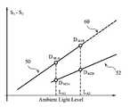
- FIG. 4shows a representation of the dependence of the difference signal from the two sensors, S 1 ⁇ S 2 , on the ambient illumination level. At low ambient light levels, the measurements are made with the backlight turned off and this gives plot 50 . At high light levels the backlight is turned on, and this gives plot 52 .
- a correction parametercould be measured at the time that the display is made and then stored in the display module, but the light output of the backlight will change and over time and therefore the correction parameter will need to be re-measured periodically.
- the inventionprovides automatic calibration of the light sensor, to be performed when moving between measurement modes. As indicated in FIG. 4 , there will be a range of ambient light levels over which it is possible to carry out measurements using both measurement modes. This is region 54 .
- the measurements made with the backlight turned offcan be used as the reference and then comparison made with measurements made with the backlight turned on, in order to calculate the correction parameters required to eliminate the contribution to the output signal resulting from the backlight.
- the two measurements D M1 and D M2which are made under the same ambient lighting conditions can be used to calculate the correction parameters.
- the output signals of the sensorshave a linear dependence on the ambient light level. In the simplest case, it can be assumed that when the measurement is made with the backlight turned on this produces an offset in the characteristics of the output signal of the sensor but that the slope of the characteristic is unchanged.
- the dotted region 60shows the plot of the measurement made with the backlight turned on, after the correction has been made.
- a correction parameter k Ocan be defined which can be added to the result of measurements made when the backlight is turned on in order to generate a result which is consistent with the measurements made when the backlight is turned off. This is illustrated by Equations 6 and 7.
- k OD M1 ⁇ D M2 Equation 6
- Corrected measurementUncorrected measurement+ k O Equation 7
- the measurements D M1 and D M2can also be considered to be results generated by processing groups of samples of the sensor outputs which have been taken over substantially the same time window.
- the slope of the sensor characteristicchanges when the mode of the ambient light measurement changes then a more complex correction is required. This might be the case if different sensors are used for measurements at high ambient light levels, for example smaller sensors may be used to measure the higher ambient light levels.
- the correction parametersmay be stored and modified over time as the display is operated under ambient lighting conditions which require the measurement mode to be varied.
- a running average of the correction parametersmay be established and stored when the display is not being used so that the parameters are available then next time that the display is turned on. If the correction parameters are not stored when the display is turned off, then they can be determined when the display is turned on by introducing the required measurements with the backlight turned off and turned on into the start-up sequence of the display.
- measurement modeswhere the display backlight is turned off or turned on has be described. However, other measurement modes may also be implemented which require a correction to be performed when switching from one mode to another in order to produce a signal which represents the ambient light level which is free from discontinuities.
- FIG. 7shows the method of the invention as a flow of processing steps.
- step 70the backlight is turned on.
- a first set of signalsis obtained in step 72 from the light sensor arrangement with the backlight on, and in the region of ambient levels where signals will be taken with the backlight on and off.
- step 74the backlight is turned off, and in step 76 , a second set of signals is obtained from the light sensor arrangement with the backlight off, for the same ambient light level (i.e. sufficiently close in time that the ambient light has not changed).
- step 78the first and second sets of signals are processed and a compensated light sensor arrangement characteristic is derived, covering both the first and second illumination source drive conditions.
- step 80the display device is controlled using a measured detected light level.
- the compensated characteristiccan be updated periodically, for example each time the ambient light levels are in the correct range.
- the illumination sourceis shown as a backlight for the sake of clarity, although it will be appreciated that front illumination display systems also exist and the invention is also applicable to such displays.
- the inventioncan be implemented using the display designs shown in FIGS. 1 and 2 , and provides a different method of processing the signals from multiple light sensors, implemented by the controller 16 for controlling the backlight and providing the computations.
- the light sensoris preferably an integrated thin film device formed using the same thin film layers used to form a display pixel array, and the light sensor may be arranged as an array of light sensor elements, with one light sensor element integrated into each display pixel, or arranged around the periphery of the display.
- the inventioncan be used to implement ambient light sensors in LCD or other light modulating displays with rear or front illumination, and enables control of the illumination source such that there is a smooth transition between the response of the light sensor arrangement between operating modes, particularly backlight-on and backlight-off modes.
- the obtained information concerning ambient light levelscan be used in known manner to adjust the backlight (or other light source) output to implement power savings in dark ambient light conditions and to ensure good image visibility in bright ambient light conditions.
- the output of the computationis used to control the illumination source of the display, but it might instead or additionally be used to control other aspects of the display operation, for example changing the brightness, contrast or gamma settings of the display, or the refresh frequency.
- One way of performing the required calculations for processing the light sensor signalsis by a computer program but the same method could be implemented using analogue or digital circuits.
- some averaging of measurement resultsmight be achieved by integrating the output obtained from the light sensing device for a number of measurements.
- This integrationcould be performed within the light sensor circuit, for example, by integrating the current from a photodiode onto a capacitor during selected measurement periods.
- Separate capacitorscan be used for the different drive conditions of the illumination source. For example, separate capacitors could be used to integrate the photodiode current during measurements which occur with the backlight on and off.
- the voltages established on the two capacitorswould then represent the sum of measurements corresponding to each of the backlight modes.
- FIGS. 5 and 6are only examples of the possible processing schemes which can be implemented.
- the relationship between light sensor output and the light levelhas been shown as perfectly linear. This does not have to be the case, and the invention applies for different transfer functions. Essentially, the best match is found in the region of overlap between the two transfer functions, so as to provide a substantially combined single transfer function.
- the output of the two measurementscan be scaled in order to take into account the different integration periods and the equations will be modified accordingly.
- the brightness of the backlightcan be changed by adjusting the pulse width or pulse frequency for a given pulse width of a pulsed illumination source output.
- the inventionmay be applied to other display types having an illumination source, such as transflective displays.
Landscapes
- Engineering & Computer Science (AREA)
- Physics & Mathematics (AREA)
- Computer Hardware Design (AREA)
- General Physics & Mathematics (AREA)
- Theoretical Computer Science (AREA)
- Liquid Crystal Display Device Control (AREA)
- Liquid Crystal (AREA)
- Control Of Indicators Other Than Cathode Ray Tubes (AREA)
- Arrangements Of Lighting Devices For Vehicle Interiors, Mounting And Supporting Thereof, Circuits Therefore (AREA)
Abstract
Description
S1=k11LA+k12kMLA+k13LB+k14LD Equation 1
S2=k21LA+k22kMLA+k23LB+k24LD Equation 2
S1−S2=(k11−k21)LA+(k12−k22)kMLA+(k13−k23)LB+(k14−k24)LD Equation 3
S1−S2=(k11−k21)LA Equation 4
S1−S2=(k11−k21)LA+(k13−k23)LB Equation 5
kO=DM1−DM2 Equation 6
Corrected measurement=Uncorrected measurement+kO Equation 7
kO=DM1A−kSDM2A Equation 9
Corrected measurement=kS×Uncorrected measurement+k0 Equation 10
Claims (17)
Priority Applications (1)
| Application Number | Priority Date | Filing Date | Title |
|---|---|---|---|
| US12/343,389US8319721B2 (en) | 2007-12-26 | 2008-12-23 | Display devices with ambient light sensing |
Applications Claiming Priority (5)
| Application Number | Priority Date | Filing Date | Title |
|---|---|---|---|
| US1660507P | 2007-12-26 | 2007-12-26 | |
| EP08161494.3 | 2008-07-30 | ||
| EP08161494AEP2075787A3 (en) | 2007-12-26 | 2008-07-30 | Display devices with ambient light sensing |
| EP08161494 | 2008-07-30 | ||
| US12/343,389US8319721B2 (en) | 2007-12-26 | 2008-12-23 | Display devices with ambient light sensing |
Publications (2)
| Publication Number | Publication Date |
|---|---|
| US20090167676A1 US20090167676A1 (en) | 2009-07-02 |
| US8319721B2true US8319721B2 (en) | 2012-11-27 |
Family
ID=40134778
Family Applications (1)
| Application Number | Title | Priority Date | Filing Date |
|---|---|---|---|
| US12/343,389Expired - Fee RelatedUS8319721B2 (en) | 2007-12-26 | 2008-12-23 | Display devices with ambient light sensing |
Country Status (5)
| Country | Link |
|---|---|
| US (1) | US8319721B2 (en) |
| EP (1) | EP2075787A3 (en) |
| JP (1) | JP2009157383A (en) |
| CN (1) | CN101477784B (en) |
| TW (1) | TWI409798B (en) |
Cited By (4)
| Publication number | Priority date | Publication date | Assignee | Title |
|---|---|---|---|---|
| US20110202151A1 (en)* | 2010-02-18 | 2011-08-18 | Redwood Systems, Inc. | Integration of computing device and lighting system |
| US20140167619A1 (en)* | 2012-12-17 | 2014-06-19 | Apple Inc. | Light Sensors For Electronic Devices |
| US8981913B2 (en) | 2010-02-18 | 2015-03-17 | Redwood Systems, Inc. | Commissioning lighting systems |
| US9572228B2 (en) | 2010-02-18 | 2017-02-14 | Redwood Systems, Inc. | Commissioning lighting systems |
Families Citing this family (15)
| Publication number | Priority date | Publication date | Assignee | Title |
|---|---|---|---|---|
| US8130204B2 (en)* | 2007-09-27 | 2012-03-06 | Visteon Global Technologies, Inc. | Environment synchronized image manipulation |
| US8006905B2 (en)* | 2008-04-18 | 2011-08-30 | Intermec Ip Corp. | Method of reducing noise in an optically read image using an optical collection device |
| US8970767B2 (en) | 2011-06-21 | 2015-03-03 | Qualcomm Mems Technologies, Inc. | Imaging method and system with angle-discrimination layer |
| US9410845B1 (en)* | 2012-12-31 | 2016-08-09 | Michael P. Toepel | Laser detecting screen |
| US10049623B2 (en)* | 2015-12-30 | 2018-08-14 | Lenovo (Beijing) Limited | Electronic device and display method |
| US10037673B1 (en) | 2017-05-01 | 2018-07-31 | Palatiumcare, Inc. | Motion-based lighting system with intelligent alerts |
| KR102400628B1 (en)* | 2017-08-17 | 2022-05-23 | 삼성전자주식회사 | Electronic device and display for reducing leakage current |
| DE102019108243B4 (en) | 2019-02-21 | 2022-06-23 | OSRAM Opto Semiconductors Gesellschaft mit beschränkter Haftung | DIODE ARRAY, ARRANGEMENT AND SYSTEM |
| TWI851719B (en)* | 2019-05-01 | 2024-08-11 | 瑞士商Ams國際公司 | Behind oled low brightness algorithm |
| US11032517B1 (en)* | 2021-02-22 | 2021-06-08 | Audie Tatum | Interactive videoconference apparatus |
| CN115705788A (en) | 2021-08-10 | 2023-02-17 | 荣耀终端有限公司 | Terminal device with ambient light detection function and ambient light detection method |
| CN113793574A (en)* | 2021-08-18 | 2021-12-14 | 南京巨鲨显示科技有限公司 | Display device based on optical sensor and calibration method thereof |
| CN115691416B (en)* | 2022-11-07 | 2025-06-17 | 维沃移动通信有限公司 | Ambient light collection method and device |
| US12298181B2 (en)* | 2023-09-06 | 2025-05-13 | Apple Inc. | Systems and methods for crosstalk mitigation between ambient light sensor and electronic display |
| CN116909049B (en)* | 2023-09-14 | 2024-01-05 | 深圳市维斯登光电有限公司 | Calibration method and system for TFT-LCD photosensitive array plate |
Citations (28)
| Publication number | Priority date | Publication date | Assignee | Title |
|---|---|---|---|---|
| US5751261A (en) | 1990-12-31 | 1998-05-12 | Kopin Corporation | Control system for display panels |
| US5831693A (en) | 1996-02-22 | 1998-11-03 | Honeywell | Integrated light sensor for an active matrix liquid crystal display panel |
| US5886681A (en) | 1996-06-14 | 1999-03-23 | Walsh; Kevin L. | Wide-range dual-backlight display apparatus |
| JP2000122575A (en) | 1998-10-20 | 2000-04-28 | Casio Comput Co Ltd | Display device |
| WO2000041378A1 (en) | 1998-12-31 | 2000-07-13 | Nokia Mobile Phones Limited | Backlight for a portable device |
| US6115091A (en) | 1996-03-29 | 2000-09-05 | Citizen Watch Co., Ltd. | Liquid crystal device with adjustable light throughput |
| US6144359A (en) | 1998-03-30 | 2000-11-07 | Rockwell Science Center | Liquid crystal displays utilizing polymer dispersed liquid crystal devices for enhanced performance and reduced power |
| US6320568B1 (en) | 1990-12-31 | 2001-11-20 | Kopin Corporation | Control system for display panels |
| US6344641B1 (en) | 1999-08-11 | 2002-02-05 | Agilent Technologies, Inc. | System and method for on-chip calibration of illumination sources for an integrated circuit display |
| WO2002037454A2 (en) | 2000-11-06 | 2002-05-10 | Nokia Corporation | White illumination |
| US20020158883A1 (en)* | 2001-04-25 | 2002-10-31 | Palm, Inc. | Control of brightness and contrast by averaging |
| WO2004001712A1 (en) | 2002-06-21 | 2003-12-31 | Nokia Corporation | Display circuit with optical sensor |
| US20040075045A1 (en) | 2001-02-13 | 2004-04-22 | Markus Hermsen | Display |
| EP1445643A1 (en) | 2001-10-16 | 2004-08-11 | Spectratech Inc. | Liquid crystal display and its correcting method |
| US20050184952A1 (en)* | 2004-02-09 | 2005-08-25 | Akitoyo Konno | Liquid crystal display apparatus |
| US20050231457A1 (en)* | 2004-02-09 | 2005-10-20 | Tsunenori Yamamoto | Liquid crystal display apparatus |
| WO2006117956A1 (en) | 2005-04-28 | 2006-11-09 | Sharp Kabushiki Kaisha | Liquid crystal display device |
| US20070126757A1 (en)* | 2004-02-19 | 2007-06-07 | Hiroshi Itoh | Video display device |
| WO2007069107A2 (en) | 2005-12-13 | 2007-06-21 | Koninklijke Philips Electronics N.V. | Display devices with ambient light sensing |
| US20070153157A1 (en) | 2005-12-30 | 2007-07-05 | Hee Kwang Kang | Liquid crystal display device and method for driving the same |
| US20070279384A1 (en)* | 2003-01-14 | 2007-12-06 | Brosnan Michael J | Apparatus for controlling a screen pointer that distinguishes between ambient light and light from its light source |
| US20080094515A1 (en)* | 2004-06-30 | 2008-04-24 | Koninklijke Philips Electronics, N.V. | Dominant color extraction for ambient light derived from video content mapped thorugh unrendered color space |
| US20080154105A1 (en)* | 2006-12-21 | 2008-06-26 | Lemay Charles | Electronic Signal Filtering System Suitable for Medical Device and Other Usage |
| US20080165116A1 (en)* | 2007-01-05 | 2008-07-10 | Herz Scott M | Backlight and Ambient Light Sensor System |
| US20090127461A1 (en)* | 2007-11-15 | 2009-05-21 | Holcombe Wayne T | Apparatus and method for display control using ambient light measurement signal from an infrared receiver |
| US20090167192A1 (en)* | 2004-06-30 | 2009-07-02 | Koninklijke Philips Electronics, N.V. | Active frame system for ambient lighting using a video display as a signal source |
| US20090167789A1 (en)* | 2007-12-26 | 2009-07-02 | Kerofsky Louis J | Methods and Systems for Backlight Modulation with Image Characteristic Mapping |
| US20100059296A9 (en)* | 2002-02-20 | 2010-03-11 | Planar Systems, Inc. | Light sensitive display |
Family Cites Families (6)
| Publication number | Priority date | Publication date | Assignee | Title |
|---|---|---|---|---|
| DE10140531A1 (en)* | 2001-08-17 | 2003-02-27 | Siemens Ag | Method and control device for lighting control |
| JP2006106294A (en)* | 2004-10-04 | 2006-04-20 | Sony Corp | Liquid crystal display |
| JP2007065004A (en)* | 2005-08-29 | 2007-03-15 | Sanyo Epson Imaging Devices Corp | Illuminance detecting method, luminance control method, electro-optical device, and electronic equipment |
| JP2007094098A (en)* | 2005-09-29 | 2007-04-12 | Sanyo Epson Imaging Devices Corp | Liquid crystal display device and electronic equipment |
| CN1987565A (en)* | 2005-12-23 | 2007-06-27 | 群康科技(深圳)有限公司 | Liquid crystal display and its back light brightness regulating method |
| CN1794044A (en)* | 2005-12-28 | 2006-06-28 | 南京Lg同创彩色显示系统有限责任公司 | Liquid crystal display capable of automatic regulating brightness and its regulating method |
- 2008
- 2008-07-30EPEP08161494Apatent/EP2075787A3/ennot_activeCeased
- 2008-12-19CNCN2008101872613Apatent/CN101477784B/enactiveActive
- 2008-12-23USUS12/343,389patent/US8319721B2/ennot_activeExpired - Fee Related
- 2008-12-25TWTW097150601Apatent/TWI409798B/ennot_activeIP Right Cessation
- 2008-12-26JPJP2008334391Apatent/JP2009157383A/enactivePending
Patent Citations (30)
| Publication number | Priority date | Publication date | Assignee | Title |
|---|---|---|---|---|
| US5751261A (en) | 1990-12-31 | 1998-05-12 | Kopin Corporation | Control system for display panels |
| US6320568B1 (en) | 1990-12-31 | 2001-11-20 | Kopin Corporation | Control system for display panels |
| US6121950A (en) | 1990-12-31 | 2000-09-19 | Kopin Corporation | Control system for display panels |
| US5831693A (en) | 1996-02-22 | 1998-11-03 | Honeywell | Integrated light sensor for an active matrix liquid crystal display panel |
| US6115091A (en) | 1996-03-29 | 2000-09-05 | Citizen Watch Co., Ltd. | Liquid crystal device with adjustable light throughput |
| US5886681A (en) | 1996-06-14 | 1999-03-23 | Walsh; Kevin L. | Wide-range dual-backlight display apparatus |
| US6144359A (en) | 1998-03-30 | 2000-11-07 | Rockwell Science Center | Liquid crystal displays utilizing polymer dispersed liquid crystal devices for enhanced performance and reduced power |
| JP2000122575A (en) | 1998-10-20 | 2000-04-28 | Casio Comput Co Ltd | Display device |
| WO2000041378A1 (en) | 1998-12-31 | 2000-07-13 | Nokia Mobile Phones Limited | Backlight for a portable device |
| US6344641B1 (en) | 1999-08-11 | 2002-02-05 | Agilent Technologies, Inc. | System and method for on-chip calibration of illumination sources for an integrated circuit display |
| WO2002037454A2 (en) | 2000-11-06 | 2002-05-10 | Nokia Corporation | White illumination |
| US20040075045A1 (en) | 2001-02-13 | 2004-04-22 | Markus Hermsen | Display |
| US20020158883A1 (en)* | 2001-04-25 | 2002-10-31 | Palm, Inc. | Control of brightness and contrast by averaging |
| EP1445643A1 (en) | 2001-10-16 | 2004-08-11 | Spectratech Inc. | Liquid crystal display and its correcting method |
| US20100059296A9 (en)* | 2002-02-20 | 2010-03-11 | Planar Systems, Inc. | Light sensitive display |
| WO2004001712A1 (en) | 2002-06-21 | 2003-12-31 | Nokia Corporation | Display circuit with optical sensor |
| US20070279384A1 (en)* | 2003-01-14 | 2007-12-06 | Brosnan Michael J | Apparatus for controlling a screen pointer that distinguishes between ambient light and light from its light source |
| US20050184952A1 (en)* | 2004-02-09 | 2005-08-25 | Akitoyo Konno | Liquid crystal display apparatus |
| US20050231457A1 (en)* | 2004-02-09 | 2005-10-20 | Tsunenori Yamamoto | Liquid crystal display apparatus |
| US20070126757A1 (en)* | 2004-02-19 | 2007-06-07 | Hiroshi Itoh | Video display device |
| US20080094515A1 (en)* | 2004-06-30 | 2008-04-24 | Koninklijke Philips Electronics, N.V. | Dominant color extraction for ambient light derived from video content mapped thorugh unrendered color space |
| US20090167192A1 (en)* | 2004-06-30 | 2009-07-02 | Koninklijke Philips Electronics, N.V. | Active frame system for ambient lighting using a video display as a signal source |
| WO2006117956A1 (en) | 2005-04-28 | 2006-11-09 | Sharp Kabushiki Kaisha | Liquid crystal display device |
| WO2007069107A2 (en) | 2005-12-13 | 2007-06-21 | Koninklijke Philips Electronics N.V. | Display devices with ambient light sensing |
| US20080284716A1 (en)* | 2005-12-13 | 2008-11-20 | Koninklijke Philips Electronics, N.V. | Display Devices With Ambient Light Sensing |
| US20070153157A1 (en) | 2005-12-30 | 2007-07-05 | Hee Kwang Kang | Liquid crystal display device and method for driving the same |
| US20080154105A1 (en)* | 2006-12-21 | 2008-06-26 | Lemay Charles | Electronic Signal Filtering System Suitable for Medical Device and Other Usage |
| US20080165116A1 (en)* | 2007-01-05 | 2008-07-10 | Herz Scott M | Backlight and Ambient Light Sensor System |
| US20090127461A1 (en)* | 2007-11-15 | 2009-05-21 | Holcombe Wayne T | Apparatus and method for display control using ambient light measurement signal from an infrared receiver |
| US20090167789A1 (en)* | 2007-12-26 | 2009-07-02 | Kerofsky Louis J | Methods and Systems for Backlight Modulation with Image Characteristic Mapping |
Non-Patent Citations (1)
| Title |
|---|
| International Search Report of Related Case International App. No. PCT/IB2006/054430. |
Cited By (6)
| Publication number | Priority date | Publication date | Assignee | Title |
|---|---|---|---|---|
| US20110202151A1 (en)* | 2010-02-18 | 2011-08-18 | Redwood Systems, Inc. | Integration of computing device and lighting system |
| US8706271B2 (en)* | 2010-02-18 | 2014-04-22 | Redwood Systems, Inc. | Integration of computing device and lighting system |
| US8981913B2 (en) | 2010-02-18 | 2015-03-17 | Redwood Systems, Inc. | Commissioning lighting systems |
| US9572228B2 (en) | 2010-02-18 | 2017-02-14 | Redwood Systems, Inc. | Commissioning lighting systems |
| US20140167619A1 (en)* | 2012-12-17 | 2014-06-19 | Apple Inc. | Light Sensors For Electronic Devices |
| US9046421B2 (en)* | 2012-12-17 | 2015-06-02 | Apple Inc. | Light sensors for electronic devices |
Also Published As
| Publication number | Publication date |
|---|---|
| EP2075787A2 (en) | 2009-07-01 |
| TW200929164A (en) | 2009-07-01 |
| CN101477784A (en) | 2009-07-08 |
| CN101477784B (en) | 2013-06-26 |
| US20090167676A1 (en) | 2009-07-02 |
| JP2009157383A (en) | 2009-07-16 |
| TWI409798B (en) | 2013-09-21 |
| EP2075787A3 (en) | 2010-07-07 |
Similar Documents
| Publication | Publication Date | Title |
|---|---|---|
| US8319721B2 (en) | Display devices with ambient light sensing | |
| US8076857B2 (en) | Display devices with ambient light sensing | |
| US20080284716A1 (en) | Display Devices With Ambient Light Sensing | |
| US10446116B2 (en) | Temperature sensor on display active area | |
| US9058769B2 (en) | Method and system for compensating ageing effects in light emitting diode display devices | |
| US20070268241A1 (en) | Display Device | |
| US8212793B2 (en) | Liquid crystal device, image sensor, and electronic apparatus | |
| US8179386B2 (en) | Optical sensor and display device provided with the same | |
| US20090066876A1 (en) | Photosensor circuit, liquid crystal display having the same and method of driving the liquid crystal display | |
| US9267849B2 (en) | Display device with temperature sensor | |
| US20100238201A1 (en) | Image display apparatus | |
| JP2009223264A (en) | Display arrangement | |
| JP2007094098A (en) | Liquid crystal display device and electronic equipment | |
| JP2006323311A (en) | Display device | |
| KR20090043457A (en) | Photodetector circuit | |
| KR20090071401A (en) | Ambient light sensing display device | |
| US20220317818A1 (en) | Display device | |
| Seetzen et al. | Self-calibrating wide color gamut high-dynamic-range display | |
| KR20090097095A (en) | Display | |
| JP2023085195A (en) | Display device and its control method | |
| JP2009257813A (en) | Light intensity detection circuit and display device | |
| JP2007163520A (en) | Display panel and display device | |
| US10832635B2 (en) | Display apparatus having display panel and humidity detection method thereof and gamma curve calibration method thereof | |
| JP2009204466A (en) | Light quantity detecting circuit and electro-optical device | |
| JP2009002727A (en) | Light quantity detecting circuit and electro-optical device |
Legal Events
| Date | Code | Title | Description |
|---|---|---|---|
| AS | Assignment | Owner name:TPO DISPLAYS CORP., TAIWAN Free format text:ASSIGNMENT OF ASSIGNORS INTEREST;ASSIGNORS:EDWARDS, MARTIN JOHN;AYRES, JOHN RICHARD;REEL/FRAME:022379/0675 Effective date:20090205 | |
| AS | Assignment | Owner name:CHIMEI INNOLUX CORPORATION, TAIWAN Free format text:MERGER;ASSIGNOR:TPO DISPLAYS CORP.;REEL/FRAME:025809/0610 Effective date:20100318 | |
| ZAAA | Notice of allowance and fees due | Free format text:ORIGINAL CODE: NOA | |
| ZAAB | Notice of allowance mailed | Free format text:ORIGINAL CODE: MN/=. | |
| ZAAA | Notice of allowance and fees due | Free format text:ORIGINAL CODE: NOA | |
| STCF | Information on status: patent grant | Free format text:PATENTED CASE | |
| AS | Assignment | Owner name:INNOLUX CORPORATION, TAIWAN Free format text:CHANGE OF NAME;ASSIGNOR:CHIMEI INNOLUX CORPORATION;REEL/FRAME:032621/0718 Effective date:20121219 | |
| FPAY | Fee payment | Year of fee payment:4 | |
| MAFP | Maintenance fee payment | Free format text:PAYMENT OF MAINTENANCE FEE, 8TH YEAR, LARGE ENTITY (ORIGINAL EVENT CODE: M1552); ENTITY STATUS OF PATENT OWNER: LARGE ENTITY Year of fee payment:8 | |
| FEPP | Fee payment procedure | Free format text:MAINTENANCE FEE REMINDER MAILED (ORIGINAL EVENT CODE: REM.); ENTITY STATUS OF PATENT OWNER: LARGE ENTITY | |
| LAPS | Lapse for failure to pay maintenance fees | Free format text:PATENT EXPIRED FOR FAILURE TO PAY MAINTENANCE FEES (ORIGINAL EVENT CODE: EXP.); ENTITY STATUS OF PATENT OWNER: LARGE ENTITY | |
| STCH | Information on status: patent discontinuation | Free format text:PATENT EXPIRED DUE TO NONPAYMENT OF MAINTENANCE FEES UNDER 37 CFR 1.362 | |
| FP | Lapsed due to failure to pay maintenance fee | Effective date:20241127 |