US8319654B2 - Apparatus having electrolysis cell and indicator light illuminating through liquid - Google Patents
Apparatus having electrolysis cell and indicator light illuminating through liquidDownload PDFInfo
- Publication number
- US8319654B2 US8319654B2US12/488,368US48836809AUS8319654B2US 8319654 B2US8319654 B2US 8319654B2US 48836809 AUS48836809 AUS 48836809AUS 8319654 B2US8319654 B2US 8319654B2
- Authority
- US
- United States
- Prior art keywords
- liquid
- electrolysis cell
- indicator light
- flow path
- container
- Prior art date
- Legal status (The legal status is an assumption and is not a legal conclusion. Google has not performed a legal analysis and makes no representation as to the accuracy of the status listed.)
- Active, expires
Links
- 239000007788liquidSubstances0.000titleclaimsabstractdescription208
- 238000005868electrolysis reactionMethods0.000titleclaimsabstractdescription159
- 230000004907fluxEffects0.000claimsabstractdescription12
- 239000007921spraySubstances0.000claimsdescription51
- 238000005286illuminationMethods0.000claimsdescription20
- 238000000034methodMethods0.000claimsdescription17
- 238000011144upstream manufacturingMethods0.000claimsdescription4
- 238000004140cleaningMethods0.000description57
- XLYOFNOQVPJJNP-UHFFFAOYSA-NwaterSubstancesOXLYOFNOQVPJJNP-UHFFFAOYSA-N0.000description44
- 239000002101nanobubbleSubstances0.000description37
- 239000012528membraneSubstances0.000description30
- 238000011012sanitizationMethods0.000description27
- 239000007789gasSubstances0.000description23
- 239000001257hydrogenSubstances0.000description19
- 229910052739hydrogenInorganic materials0.000description19
- 150000002500ionsChemical class0.000description17
- 239000008399tap waterSubstances0.000description17
- 235000020679tap waterNutrition0.000description17
- BASFCYQUMIYNBI-UHFFFAOYSA-NplatinumChemical compound[Pt]BASFCYQUMIYNBI-UHFFFAOYSA-N0.000description16
- 230000006870functionEffects0.000description15
- 239000000463materialSubstances0.000description15
- UFHFLCQGNIYNRP-UHFFFAOYSA-NHydrogenChemical compound[H][H]UFHFLCQGNIYNRP-UHFFFAOYSA-N0.000description14
- 229920001940conductive polymerPolymers0.000description14
- 238000010586diagramMethods0.000description14
- 239000012071phaseSubstances0.000description14
- 239000012530fluidSubstances0.000description13
- 239000002245particleSubstances0.000description13
- -1hydrogen ionsChemical class0.000description10
- 239000003014ion exchange membraneSubstances0.000description10
- 239000000203mixtureSubstances0.000description10
- 229910052697platinumInorganic materials0.000description9
- 239000000243solutionSubstances0.000description9
- 238000001994activationMethods0.000description8
- 238000005341cation exchangeMethods0.000description8
- 238000006243chemical reactionMethods0.000description8
- MHYCRLGKOZWVEF-UHFFFAOYSA-Nethyl acetate;hydrateChemical compoundO.CCOC(C)=OMHYCRLGKOZWVEF-UHFFFAOYSA-N0.000description7
- RTAQQCXQSZGOHL-UHFFFAOYSA-NTitaniumChemical compound[Ti]RTAQQCXQSZGOHL-UHFFFAOYSA-N0.000description6
- 150000001768cationsChemical class0.000description6
- 238000010276constructionMethods0.000description6
- 230000008569processEffects0.000description6
- 239000010936titaniumSubstances0.000description6
- 229910052719titaniumInorganic materials0.000description6
- 230000000694effectsEffects0.000description5
- 229920000554ionomerPolymers0.000description5
- 230000001788irregularEffects0.000description5
- 230000002829reductive effectEffects0.000description5
- 230000004913activationEffects0.000description4
- 125000004429atomChemical group0.000description4
- 239000007795chemical reaction productSubstances0.000description4
- 230000000994depressogenic effectEffects0.000description4
- 230000005661hydrophobic surfaceEffects0.000description4
- 239000004033plasticSubstances0.000description4
- 229920003023plasticPolymers0.000description4
- 239000004065semiconductorSubstances0.000description4
- 239000007787solidSubstances0.000description4
- 230000000007visual effectEffects0.000description4
- QVGXLLKOCUKJST-UHFFFAOYSA-Natomic oxygenChemical compound[O]QVGXLLKOCUKJST-UHFFFAOYSA-N0.000description3
- 230000009286beneficial effectEffects0.000description3
- 230000008859changeEffects0.000description3
- 230000007423decreaseEffects0.000description3
- 150000004679hydroxidesChemical class0.000description3
- 230000001965increasing effectEffects0.000description3
- 230000000670limiting effectEffects0.000description3
- 239000007791liquid phaseSubstances0.000description3
- 230000033116oxidation-reduction processEffects0.000description3
- 239000001301oxygenSubstances0.000description3
- 229910052760oxygenInorganic materials0.000description3
- 239000010970precious metalSubstances0.000description3
- 238000011084recoveryMethods0.000description3
- 230000009467reductionEffects0.000description3
- 229920003934Aciplex®Polymers0.000description2
- 229920000557Nafion®Polymers0.000description2
- FAPWRFPIFSIZLT-UHFFFAOYSA-MSodium chlorideChemical compound[Na+].[Cl-]FAPWRFPIFSIZLT-UHFFFAOYSA-M0.000description2
- 230000002378acidificating effectEffects0.000description2
- 230000009471actionEffects0.000description2
- 239000003011anion exchange membraneSubstances0.000description2
- 150000001450anionsChemical class0.000description2
- 230000004888barrier functionEffects0.000description2
- 230000015572biosynthetic processEffects0.000description2
- 150000003841chloride saltsChemical class0.000description2
- 239000003086colorantSubstances0.000description2
- 150000001875compoundsChemical class0.000description2
- 238000009826distributionMethods0.000description2
- 230000005684electric fieldEffects0.000description2
- 239000007772electrode materialSubstances0.000description2
- 230000002349favourable effectEffects0.000description2
- 230000036571hydrationEffects0.000description2
- 238000006703hydration reactionMethods0.000description2
- 150000002431hydrogenChemical class0.000description2
- 238000002347injectionMethods0.000description2
- 239000007924injectionSubstances0.000description2
- 230000003993interactionEffects0.000description2
- 229910052751metalInorganic materials0.000description2
- 239000002184metalSubstances0.000description2
- 229910052987metal hydrideInorganic materials0.000description2
- 230000002441reversible effectEffects0.000description2
- 239000003981vehicleSubstances0.000description2
- KZBUYRJDOAKODT-UHFFFAOYSA-NChlorineChemical compoundClClKZBUYRJDOAKODT-UHFFFAOYSA-N0.000description1
- ZAMOUSCENKQFHK-UHFFFAOYSA-NChlorine atomChemical compound[Cl]ZAMOUSCENKQFHK-UHFFFAOYSA-N0.000description1
- 239000004821Contact adhesiveSubstances0.000description1
- MYMOFIZGZYHOMD-UHFFFAOYSA-NDioxygenChemical compoundO=OMYMOFIZGZYHOMD-UHFFFAOYSA-N0.000description1
- 241000555828EurypharyngidaeSpecies0.000description1
- 229920003935Flemion®Polymers0.000description1
- DGAQECJNVWCQMB-PUAWFVPOSA-MIlexoside XXIXChemical compoundC[C@@H]1CC[C@@]2(CC[C@@]3(C(=CC[C@H]4[C@]3(CC[C@@H]5[C@@]4(CC[C@@H](C5(C)C)OS(=O)(=O)[O-])C)C)[C@@H]2[C@]1(C)O)C)C(=O)O[C@H]6[C@@H]([C@H]([C@@H]([C@H](O6)CO)O)O)O.[Na+]DGAQECJNVWCQMB-PUAWFVPOSA-M0.000description1
- 239000000853adhesiveSubstances0.000description1
- 230000001070adhesive effectEffects0.000description1
- 230000004075alterationEffects0.000description1
- 230000008901benefitEffects0.000description1
- 150000001732carboxylic acid derivativesChemical class0.000description1
- 230000003197catalytic effectEffects0.000description1
- 239000003010cation ion exchange membraneSubstances0.000description1
- 239000002801charged materialSubstances0.000description1
- 239000000460chlorineSubstances0.000description1
- 229910052801chlorineInorganic materials0.000description1
- 239000011248coating agentSubstances0.000description1
- 238000000576coating methodMethods0.000description1
- 238000002485combustion reactionMethods0.000description1
- 229920001577copolymerPolymers0.000description1
- 238000009792diffusion processMethods0.000description1
- 229910001882dioxygenInorganic materials0.000description1
- 238000006073displacement reactionMethods0.000description1
- 238000003487electrochemical reactionMethods0.000description1
- 239000003792electrolyteSubstances0.000description1
- 239000000446fuelSubstances0.000description1
- 125000004435hydrogen atomChemical group[H]*0.000description1
- 230000001939inductive effectEffects0.000description1
- 229910052500inorganic mineralInorganic materials0.000description1
- 239000010410layerSubstances0.000description1
- 238000011068loading methodMethods0.000description1
- 238000012423maintenanceMethods0.000description1
- 238000004519manufacturing processMethods0.000description1
- 239000007769metal materialSubstances0.000description1
- 239000011707mineralSubstances0.000description1
- 239000003595mistSubstances0.000description1
- 238000002156mixingMethods0.000description1
- 230000004048modificationEffects0.000description1
- 238000012986modificationMethods0.000description1
- 125000004430oxygen atomChemical groupO*0.000description1
- 230000036961partial effectEffects0.000description1
- 238000007747platingMethods0.000description1
- 229920000515polycarbonatePolymers0.000description1
- 239000004417polycarbonateSubstances0.000description1
- 229920000728polyesterPolymers0.000description1
- 239000011241protective layerSubstances0.000description1
- 230000008672reprogrammingEffects0.000description1
- 230000004044responseEffects0.000description1
- 230000000717retained effectEffects0.000description1
- 150000003839saltsChemical group0.000description1
- 239000011734sodiumSubstances0.000description1
- 229910052708sodiumInorganic materials0.000description1
- 239000011780sodium chlorideSubstances0.000description1
- 238000005507sprayingMethods0.000description1
- 229910001220stainless steelInorganic materials0.000description1
- 239000010935stainless steelSubstances0.000description1
- 230000003068static effectEffects0.000description1
- 238000003860storageMethods0.000description1
- 239000000126substanceSubstances0.000description1
- 150000003460sulfonic acidsChemical class0.000description1
- 230000008093supporting effectEffects0.000description1
- 239000002344surface layerSubstances0.000description1
- 239000002352surface waterSubstances0.000description1
- 239000000725suspensionSubstances0.000description1
- 230000001960triggered effectEffects0.000description1
- 125000000391vinyl groupChemical group[H]C([*])=C([H])[H]0.000description1
- 229920002554vinyl polymerPolymers0.000description1
- 239000002699waste materialSubstances0.000description1
Images


Classifications
- C—CHEMISTRY; METALLURGY
- C02—TREATMENT OF WATER, WASTE WATER, SEWAGE, OR SLUDGE
- C02F—TREATMENT OF WATER, WASTE WATER, SEWAGE, OR SLUDGE
- C02F1/00—Treatment of water, waste water, or sewage
- C02F1/46—Treatment of water, waste water, or sewage by electrochemical methods
- C02F1/461—Treatment of water, waste water, or sewage by electrochemical methods by electrolysis
- C02F1/46104—Devices therefor; Their operating or servicing
- C02F1/4618—Devices therefor; Their operating or servicing for producing "ionised" acidic or basic water
- C—CHEMISTRY; METALLURGY
- C02—TREATMENT OF WATER, WASTE WATER, SEWAGE, OR SLUDGE
- C02F—TREATMENT OF WATER, WASTE WATER, SEWAGE, OR SLUDGE
- C02F1/00—Treatment of water, waste water, or sewage
- C02F1/46—Treatment of water, waste water, or sewage by electrochemical methods
- C02F1/461—Treatment of water, waste water, or sewage by electrochemical methods by electrolysis
- A—HUMAN NECESSITIES
- A47—FURNITURE; DOMESTIC ARTICLES OR APPLIANCES; COFFEE MILLS; SPICE MILLS; SUCTION CLEANERS IN GENERAL
- A47L—DOMESTIC WASHING OR CLEANING; SUCTION CLEANERS IN GENERAL
- A47L13/00—Implements for cleaning floors, carpets, furniture, walls, or wall coverings
- A47L13/10—Scrubbing; Scouring; Cleaning; Polishing
- A47L13/26—Other cleaning devices with liquid supply arrangements
- A—HUMAN NECESSITIES
- A61—MEDICAL OR VETERINARY SCIENCE; HYGIENE
- A61L—METHODS OR APPARATUS FOR STERILISING MATERIALS OR OBJECTS IN GENERAL; DISINFECTION, STERILISATION OR DEODORISATION OF AIR; CHEMICAL ASPECTS OF BANDAGES, DRESSINGS, ABSORBENT PADS OR SURGICAL ARTICLES; MATERIALS FOR BANDAGES, DRESSINGS, ABSORBENT PADS OR SURGICAL ARTICLES
- A61L2/00—Methods or apparatus for disinfecting or sterilising materials or objects other than foodstuffs or contact lenses; Accessories therefor
- A61L2/16—Methods or apparatus for disinfecting or sterilising materials or objects other than foodstuffs or contact lenses; Accessories therefor using chemical substances
- A61L2/18—Liquid substances or solutions comprising solids or dissolved gases
- B—PERFORMING OPERATIONS; TRANSPORTING
- B05—SPRAYING OR ATOMISING IN GENERAL; APPLYING FLUENT MATERIALS TO SURFACES, IN GENERAL
- B05B—SPRAYING APPARATUS; ATOMISING APPARATUS; NOZZLES
- B05B11/00—Single-unit hand-held apparatus in which flow of contents is produced by the muscular force of the operator at the moment of use
- B—PERFORMING OPERATIONS; TRANSPORTING
- B08—CLEANING
- B08B—CLEANING IN GENERAL; PREVENTION OF FOULING IN GENERAL
- B08B3/00—Cleaning by methods involving the use or presence of liquid or steam
- B08B3/04—Cleaning involving contact with liquid
- B08B3/08—Cleaning involving contact with liquid the liquid having chemical or dissolving effect
- A—HUMAN NECESSITIES
- A61—MEDICAL OR VETERINARY SCIENCE; HYGIENE
- A61L—METHODS OR APPARATUS FOR STERILISING MATERIALS OR OBJECTS IN GENERAL; DISINFECTION, STERILISATION OR DEODORISATION OF AIR; CHEMICAL ASPECTS OF BANDAGES, DRESSINGS, ABSORBENT PADS OR SURGICAL ARTICLES; MATERIALS FOR BANDAGES, DRESSINGS, ABSORBENT PADS OR SURGICAL ARTICLES
- A61L2/00—Methods or apparatus for disinfecting or sterilising materials or objects other than foodstuffs or contact lenses; Accessories therefor
- A61L2/02—Methods or apparatus for disinfecting or sterilising materials or objects other than foodstuffs or contact lenses; Accessories therefor using physical phenomena
- A61L2/03—Electric current
- A61L2/035—Electrolysis
- A—HUMAN NECESSITIES
- A61—MEDICAL OR VETERINARY SCIENCE; HYGIENE
- A61L—METHODS OR APPARATUS FOR STERILISING MATERIALS OR OBJECTS IN GENERAL; DISINFECTION, STERILISATION OR DEODORISATION OF AIR; CHEMICAL ASPECTS OF BANDAGES, DRESSINGS, ABSORBENT PADS OR SURGICAL ARTICLES; MATERIALS FOR BANDAGES, DRESSINGS, ABSORBENT PADS OR SURGICAL ARTICLES
- A61L2/00—Methods or apparatus for disinfecting or sterilising materials or objects other than foodstuffs or contact lenses; Accessories therefor
- A61L2/16—Methods or apparatus for disinfecting or sterilising materials or objects other than foodstuffs or contact lenses; Accessories therefor using chemical substances
- A61L2/22—Phase substances, e.g. smokes, aerosols or sprayed or atomised substances
- C—CHEMISTRY; METALLURGY
- C02—TREATMENT OF WATER, WASTE WATER, SEWAGE, OR SLUDGE
- C02F—TREATMENT OF WATER, WASTE WATER, SEWAGE, OR SLUDGE
- C02F1/00—Treatment of water, waste water, or sewage
- C02F1/46—Treatment of water, waste water, or sewage by electrochemical methods
- C02F1/461—Treatment of water, waste water, or sewage by electrochemical methods by electrolysis
- C02F1/46104—Devices therefor; Their operating or servicing
- C02F1/46109—Electrodes
- C02F2001/46119—Cleaning the electrodes
- C—CHEMISTRY; METALLURGY
- C02—TREATMENT OF WATER, WASTE WATER, SEWAGE, OR SLUDGE
- C02F—TREATMENT OF WATER, WASTE WATER, SEWAGE, OR SLUDGE
- C02F1/00—Treatment of water, waste water, or sewage
- C02F1/46—Treatment of water, waste water, or sewage by electrochemical methods
- C02F1/461—Treatment of water, waste water, or sewage by electrochemical methods by electrolysis
- C02F1/46104—Devices therefor; Their operating or servicing
- C02F1/46109—Electrodes
- C02F2001/46133—Electrodes characterised by the material
- C—CHEMISTRY; METALLURGY
- C02—TREATMENT OF WATER, WASTE WATER, SEWAGE, OR SLUDGE
- C02F—TREATMENT OF WATER, WASTE WATER, SEWAGE, OR SLUDGE
- C02F1/00—Treatment of water, waste water, or sewage
- C02F1/46—Treatment of water, waste water, or sewage by electrochemical methods
- C02F1/461—Treatment of water, waste water, or sewage by electrochemical methods by electrolysis
- C02F1/46104—Devices therefor; Their operating or servicing
- C02F1/46109—Electrodes
- C02F2001/46152—Electrodes characterised by the shape or form
- C02F2001/46157—Perforated or foraminous electrodes
- C—CHEMISTRY; METALLURGY
- C02—TREATMENT OF WATER, WASTE WATER, SEWAGE, OR SLUDGE
- C02F—TREATMENT OF WATER, WASTE WATER, SEWAGE, OR SLUDGE
- C02F1/00—Treatment of water, waste water, or sewage
- C02F1/46—Treatment of water, waste water, or sewage by electrochemical methods
- C02F1/461—Treatment of water, waste water, or sewage by electrochemical methods by electrolysis
- C02F1/46104—Devices therefor; Their operating or servicing
- C02F1/4618—Devices therefor; Their operating or servicing for producing "ionised" acidic or basic water
- C02F2001/46185—Devices therefor; Their operating or servicing for producing "ionised" acidic or basic water only anodic or acidic water, e.g. for oxidizing or sterilizing
- C—CHEMISTRY; METALLURGY
- C02—TREATMENT OF WATER, WASTE WATER, SEWAGE, OR SLUDGE
- C02F—TREATMENT OF WATER, WASTE WATER, SEWAGE, OR SLUDGE
- C02F1/00—Treatment of water, waste water, or sewage
- C02F1/46—Treatment of water, waste water, or sewage by electrochemical methods
- C02F1/461—Treatment of water, waste water, or sewage by electrochemical methods by electrolysis
- C02F1/46104—Devices therefor; Their operating or servicing
- C02F1/4618—Devices therefor; Their operating or servicing for producing "ionised" acidic or basic water
- C02F2001/4619—Devices therefor; Their operating or servicing for producing "ionised" acidic or basic water only cathodic or alkaline water, e.g. for reducing
- C—CHEMISTRY; METALLURGY
- C02—TREATMENT OF WATER, WASTE WATER, SEWAGE, OR SLUDGE
- C02F—TREATMENT OF WATER, WASTE WATER, SEWAGE, OR SLUDGE
- C02F2201/00—Apparatus for treatment of water, waste water or sewage
- C02F2201/002—Construction details of the apparatus
- C02F2201/003—Coaxial constructions, e.g. a cartridge located coaxially within another
- C—CHEMISTRY; METALLURGY
- C02—TREATMENT OF WATER, WASTE WATER, SEWAGE, OR SLUDGE
- C02F—TREATMENT OF WATER, WASTE WATER, SEWAGE, OR SLUDGE
- C02F2201/00—Apparatus for treatment of water, waste water or sewage
- C02F2201/008—Mobile apparatus and plants, e.g. mounted on a vehicle
- C—CHEMISTRY; METALLURGY
- C02—TREATMENT OF WATER, WASTE WATER, SEWAGE, OR SLUDGE
- C02F—TREATMENT OF WATER, WASTE WATER, SEWAGE, OR SLUDGE
- C02F2201/00—Apparatus for treatment of water, waste water or sewage
- C02F2201/46—Apparatus for electrochemical processes
- C02F2201/461—Electrolysis apparatus
- C02F2201/46105—Details relating to the electrolytic devices
- C02F2201/46115—Electrolytic cell with membranes or diaphragms
- C—CHEMISTRY; METALLURGY
- C02—TREATMENT OF WATER, WASTE WATER, SEWAGE, OR SLUDGE
- C02F—TREATMENT OF WATER, WASTE WATER, SEWAGE, OR SLUDGE
- C02F2201/00—Apparatus for treatment of water, waste water or sewage
- C02F2201/46—Apparatus for electrochemical processes
- C02F2201/461—Electrolysis apparatus
- C02F2201/46105—Details relating to the electrolytic devices
- C02F2201/4612—Controlling or monitoring
- C02F2201/46125—Electrical variables
- C02F2201/4613—Inversing polarity
- C—CHEMISTRY; METALLURGY
- C02—TREATMENT OF WATER, WASTE WATER, SEWAGE, OR SLUDGE
- C02F—TREATMENT OF WATER, WASTE WATER, SEWAGE, OR SLUDGE
- C02F2201/00—Apparatus for treatment of water, waste water or sewage
- C02F2201/46—Apparatus for electrochemical processes
- C02F2201/461—Electrolysis apparatus
- C02F2201/46105—Details relating to the electrolytic devices
- C02F2201/4612—Controlling or monitoring
- C02F2201/46125—Electrical variables
- C02F2201/46135—Voltage
- C—CHEMISTRY; METALLURGY
- C02—TREATMENT OF WATER, WASTE WATER, SEWAGE, OR SLUDGE
- C02F—TREATMENT OF WATER, WASTE WATER, SEWAGE, OR SLUDGE
- C02F2201/00—Apparatus for treatment of water, waste water or sewage
- C02F2201/46—Apparatus for electrochemical processes
- C02F2201/461—Electrolysis apparatus
- C02F2201/46105—Details relating to the electrolytic devices
- C02F2201/4612—Controlling or monitoring
- C02F2201/4615—Time
- C—CHEMISTRY; METALLURGY
- C02—TREATMENT OF WATER, WASTE WATER, SEWAGE, OR SLUDGE
- C02F—TREATMENT OF WATER, WASTE WATER, SEWAGE, OR SLUDGE
- C02F2201/00—Apparatus for treatment of water, waste water or sewage
- C02F2201/46—Apparatus for electrochemical processes
- C02F2201/461—Electrolysis apparatus
- C02F2201/46105—Details relating to the electrolytic devices
- C02F2201/4616—Power supply
- C02F2201/4617—DC only
- C—CHEMISTRY; METALLURGY
- C02—TREATMENT OF WATER, WASTE WATER, SEWAGE, OR SLUDGE
- C02F—TREATMENT OF WATER, WASTE WATER, SEWAGE, OR SLUDGE
- C02F2201/00—Apparatus for treatment of water, waste water or sewage
- C02F2201/46—Apparatus for electrochemical processes
- C02F2201/461—Electrolysis apparatus
- C02F2201/46105—Details relating to the electrolytic devices
- C02F2201/4618—Supplying or removing reactants or electrolyte
- C—CHEMISTRY; METALLURGY
- C02—TREATMENT OF WATER, WASTE WATER, SEWAGE, OR SLUDGE
- C02F—TREATMENT OF WATER, WASTE WATER, SEWAGE, OR SLUDGE
- C02F2209/00—Controlling or monitoring parameters in water treatment
- C02F2209/005—Processes using a programmable logic controller [PLC]
- C02F2209/006—Processes using a programmable logic controller [PLC] comprising a software program or a logic diagram
- C—CHEMISTRY; METALLURGY
- C02—TREATMENT OF WATER, WASTE WATER, SEWAGE, OR SLUDGE
- C02F—TREATMENT OF WATER, WASTE WATER, SEWAGE, OR SLUDGE
- C02F2209/00—Controlling or monitoring parameters in water treatment
- C02F2209/04—Oxidation reduction potential [ORP]
- C—CHEMISTRY; METALLURGY
- C02—TREATMENT OF WATER, WASTE WATER, SEWAGE, OR SLUDGE
- C02F—TREATMENT OF WATER, WASTE WATER, SEWAGE, OR SLUDGE
- C02F2303/00—Specific treatment goals
- C02F2303/04—Disinfection
- C—CHEMISTRY; METALLURGY
- C02—TREATMENT OF WATER, WASTE WATER, SEWAGE, OR SLUDGE
- C02F—TREATMENT OF WATER, WASTE WATER, SEWAGE, OR SLUDGE
- C02F2307/00—Location of water treatment or water treatment device
- C02F2307/02—Location of water treatment or water treatment device as part of a bottle
- Y—GENERAL TAGGING OF NEW TECHNOLOGICAL DEVELOPMENTS; GENERAL TAGGING OF CROSS-SECTIONAL TECHNOLOGIES SPANNING OVER SEVERAL SECTIONS OF THE IPC; TECHNICAL SUBJECTS COVERED BY FORMER USPC CROSS-REFERENCE ART COLLECTIONS [XRACs] AND DIGESTS
- Y02—TECHNOLOGIES OR APPLICATIONS FOR MITIGATION OR ADAPTATION AGAINST CLIMATE CHANGE
- Y02E—REDUCTION OF GREENHOUSE GAS [GHG] EMISSIONS, RELATED TO ENERGY GENERATION, TRANSMISSION OR DISTRIBUTION
- Y02E60/00—Enabling technologies; Technologies with a potential or indirect contribution to GHG emissions mitigation
- Y02E60/30—Hydrogen technology
- Y02E60/36—Hydrogen production from non-carbon containing sources, e.g. by water electrolysis
Definitions
- the present disclosurerelates to electrochemical activation of fluids and, more particularly, to electrolysis cells and corresponding methods.
- Electrolysis cellsare used in a variety of different applications for changing one or more characteristics of a fluid. For example, electrolysis cells have been used in cleaning/sanitizing applications, medical industries, and semiconductor manufacturing processes. Electrolysis cells have also been used in a variety of other applications and have had different configurations.
- electrolysis cellsare used to create anolyte electrochemically activated (EA) liquid and catholyte EA liquid.
- EAelectrochemically activated
- Anolyte EA liquidshave known sanitizing properties
- catholyte EA liquidshave known cleaning properties. Examples of cleaning and/or sanitizing systems are disclosed in Field et al. U.S. Publication No. 2007/0186368 A1, published Aug. 16, 2007.
- An aspect of the disclosurerelates to an apparatus, which includes an electrolysis cell, a liquid flow path that passes through the electrolysis cell, and an indicator light.
- the indicator lightis illuminated as a function of an operating characteristic of the electrolysis cell, and luminous flux radiated from the light illuminates liquid along at least a portion of the flow path.
- the methodincludes: carrying a liquid in a hand-held spray bottle; electrolyzing the liquid with an electrolysis cell carried by the bottle to produce electrolyzed liquid; dispensing the electrolyzed liquid; sensing an operating characteristic of the electrolysis cell; illuminating at least a portion of at least one of the liquid or the electrolyzed liquid as a function of the operating characteristic.
- the bottleincludes a container, a nozzle, and a liquid flow path from the container to the nozzle.
- An electrolysis cell and a pumpare coupled in the flow path.
- An indicator lightis positioned to illuminate at least one of the container or the flow path.
- the indicator lightincludes:
- illumination of at least one of the container or the flow pathis visible from a viewpoint that is external to the bottle.
- the indicator lightis positioned such that luminous flux from the indicator light passes through liquid contained in at least one of the container or the flow path and is visible from a viewpoint that is external to the bottle.
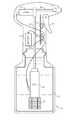
- FIG. 1is a simplified, schematic diagram of a hand-held spray bottle according to an exemplary aspect of the present disclosure.
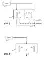
- FIG. 2illustrates an example of an electrolysis cell having an ion-selective membrane.
- FIG. 3illustrates an electrolysis cell having no ion-selective membrane according to a further example of the disclosure.
- FIG. 4Ais a fragmentary view of a conductive polymer electrode having a plurality of rectilinear apertures in a regular grid pattern according to an aspect of the disclosure.
- FIG. 4Bis a fragmentary view of a conductive polymer electrode having a plurality of curvilinear apertures of different sizes in a regular grid pattern according to another example.
- FIG. 4Cis a fragmentary view of a conductive polymer electrode having a plurality of irregular and regular shaped apertures having a variety of different shapes and sizes according to another example.
- FIG. 5illustrates an example of an electrolysis cell having a tubular shape according to one illustrative example.
- FIG. 6is a waveform diagram illustrating the voltage pattern applied to the anode and cathode according to an exemplary aspect of the present disclosure.
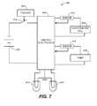
- FIG. 7is a block diagram of a system having an indicator according to an embodiment of the disclosure, which can be incorporated into any of the embodiments disclosed herein, for example.
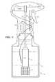
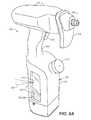
- FIG. 8Ais a perspective view of a spray bottle having an indicator light that illuminates through liquid carried by the bottle.
- FIG. 8Bis a perspective view of a spray bottle having an indicator light that illuminates through liquid carried by the bottle, according to an alternative embodiment of the disclosure.
- FIG. 8Cis a rear, perspective view of a head of the bottle shown in FIG. 8B .
- FIGS. 9A and 9Bare perspective views of a left-hand side housing
- FIG. 9Cis a perspective view of a right-hand side housing of the bottle shown in FIG. 8B .
- FIG. 10illustrates various components installed in the left-hand side housing.
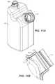
- FIGS. 11A and 11Billustrate a liquid container carried by the bottle shown in FIG. 8B .
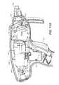
- FIG. 12Aillustrates a fragmentary, close-up view of a pump/cell assembly installed in a barrel of the housing.
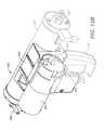
- FIG. 12Bis a perspective view of the pump/cell assembly removed from the housing.
- FIG. 12Cis a bottom, perspective view of the pump/cell assembly with the trigger removed.
- FIG. 13illustrates an exploded, perspective view of a mounting bracket of the assembly shown in FIGS. 12A-12C .
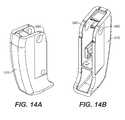
- FIGS. 14A and 14Bare perspective views of a trigger of the bottle shown in FIG. 8B .
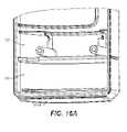
- FIGS. 15A and 15Bare perspective views of a trigger boot, which overlies the trigger.
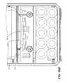
- FIG. 16Aillustrates lower compartments of a housing half in greater detail.
- FIG. 16Billustrates a circuit board and batteries mounted within the compartments shown in FIG. 16A .
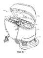
- FIG. 17is a perspective view of a mobile cleaning machine, which implements an electrolysis cell according to an example of the present disclosure.
- FIG. 18is a simplified block diagram of an electrolysis cell that is mounted to a platform according to another embodiment.
- FIG. 19is a perspective view of an all-surface cleaner according to another embodiment of the disclosure.
- FIG. 20is a block diagram illustrating a control circuit for controlling the various components within the hand-held spray bottle shown in FIGS. 8-16 according to an illustrating example of the disclosure.
- An aspect of the present disclosureis directed to a method and apparatus for electrolyzing liquids.
- Electrolysis cellscan be used in a variety of different applications and housed in a variety of different types of apparatus, which can be hand-held, mobile, immobile, wall-mounted, motorized or non-motorized cleaning/sanitizing vehicle, wheeled, etc, for example.
- an electrolysis cellis incorporated in a hand-held spray bottle.
- FIG. 1is a simplified, schematic diagram of a hand-held spray bottle 10 according to an exemplary aspect of the present disclosure.
- Spray bottle 10includes a reservoir 12 for containing a liquid to be treated and then dispensed through a nozzle 14 .
- the liquid to be treatedincludes an aqueous composition, such as regular tap water.
- Spray bottle 10further includes an inlet filter 16 , one or more electrolysis cells 18 , tubes 20 and 22 , pump 24 , actuator 26 , switch 28 , circuit board and control electronics 30 and batteries 32 .
- tubes 20 and 22may be housed within a neck and barrel, respectively of bottle 10 , for example.
- a cap 34seals reservoir 12 around the neck of bottle 10 .
- Batteries 32can include disposable batteries and/or rechargeable batteries, for example, and provide electrical power to electrolysis cell 18 and pump 24 when energized by circuit board and control electronics 30 .
- actuator 26is a trigger-style actuator, which actuates momentary switch 28 between open and closed states. For example, when the user “squeezes” the hand trigger to a squeezed state, the trigger actuates the switch into the closed state. When the user releases the hand trigger, trigger actuates the switch into the open state.
- actuator 26can have other styles in alternative embodiments and can be eliminated in further embodiments.
- switch 28can be actuated directly by the user.
- control electronics 30de-energizes electrolysis cell 18 and pump 24 .
- switch 28is in the closed, conducting state, control electronics 30 energizes electrolysis cell 18 and pump 24 .
- nozzle 14may or may not be adjustable, so as to select between squirting a stream, aerosolizing a mist, or dispensing a spray, for example.
- pump 24is replaced with a mechanical pump, such as a hand-triggered positive displacement pump, wherein actuator trigger 26 acts directly on the pump by mechanical action.
- switch 28could be separately actuated from the pump 24 , such as a power switch, to energize electrolysis cell 18 .
- batteries 32are eliminated and power is delivered to spray bottle 10 from an external source, such as through a power cord, plug, and/or contact terminals.
- Spray bottle 10can have any other structural and/or functional arrangement.
- pump 24can be located downstream of cell 18 , as shown in FIG. 1 , or upstream of cell 18 with respect to the direction of fluid flow from reservoir 12 to nozzle 14 .
- the spray bottlecontains a liquid to be sprayed on a surface to be cleaned and/or sanitized.
- electrolysis cell 18converts the liquid to an anolyte EA liquid and a catholyte EA liquid prior to being dispensed from the bottle as an output spray.
- the anolyte and catholyte EA liquidscan be dispensed as a combined mixture or as separate spray outputs, such as through separate tubes and/or nozzles. In the embodiment shown in FIG. 1 , the anolyte and catholyte EA liquids are dispensed as a combined mixture.
- electrolysis cell 18can have a small package and be powered by batteries carried by the package or spray bottle, for example.
- An electrolysis cellincludes any fluid treatment cell that is adapted to apply an electric field across the fluid between at least one anode electrode and at least one cathode electrode.
- An electrolysis cellcan have any suitable number of electrodes, any suitable number of chambers for containing the fluid, and any suitable number of fluid inputs and fluid outputs.
- the cellcan be adapted to treat any fluid (such as a liquid or gas-liquid combination).
- the cellcan include one or more ion-selective membranes between the anode and cathode or can be configured without any ion selective membranes.
- An electrolysis cell having an ion-selective membraneis referred to herein as a “functional generator”.
- Electrolysis cellscan be used in a variety of different applications and can have a variety of different structures, such as but not limited to a spray bottle as discussed with reference to FIG. 1 , and/or the structures disclosed in Field et al. U.S. Patent Publication No. 2007/0186368, published Aug. 16, 2007.
- a spray bottleas discussed with reference to FIG. 1
- a spray bottleas discussed with reference to FIG. 1
- various elements and processes relating to electrolysisare described herein relative to the context of a spray bottle, these elements and processes can be applied to, and incorporated in, other, non-spray bottle applications.
- FIG. 2is a schematic diagram illustrating an example of an electrolysis cell 50 that can be used in the spray bottle shown in FIG. 1 , for example.
- Electrolysis cell 50and which receives liquid to be treated from a liquid source 52 .
- Liquid source 52can include a tank or other solution reservoir, such as reservoir 12 in FIG. 1 , or can include a fitting or other inlet for receiving a liquid from an external source.
- Cell 50has one or more anode chambers 54 and one or more cathode chambers 56 (known as reaction chambers), which are separated by an ion exchange membrane 58 , such as a cation or anion exchange membrane.
- anode electrodes 60 and cathode electrodes 62are disposed in each anode chamber 54 and each cathode chamber 56 , respectively.
- the anode and cathode electrodes 60 , 62can be made from any suitable material, such as a conductive polymer, titanium and/or titanium coated with a precious metal, such as platinum, or any other suitable electrode material.
- At least one of the anode or cathodeis at least partially or wholly made from a conductive polymer.
- the electrodes and respective chamberscan have any suitable shape and construction.
- the electrodescan be flat plates, coaxial plates, rods, or a combination thereof.
- Each electrodecan have, for example, a solid construction or can have one or more apertures.
- each electrodeis formed as a mesh.
- multiple cells 50can be coupled in series or in parallel with one another, for example.
- the electrodes 60 , 62are electrically connected to opposite terminals of a conventional power supply (not shown). Ion exchange membrane 58 is located between electrodes 60 and 62 .
- the power supplycan provide a constant DC output voltage, a pulsed or otherwise modulated DC output voltage, and/or a pulsed or otherwise modulated AC output voltage to the anode and cathode electrodes.
- the power supplycan have any suitable output voltage level, current level, duty cycle or waveform.
- the power supplyapplies the voltage supplied to the plates at a relative steady state.
- the power supply(and/or control electronics) includes a DC/DC converter that uses a pulse-width modulation (PWM) control scheme to control voltage and current output.
- PWMpulse-width modulation
- Other types of power suppliescan also be used, which can be pulsed or not pulsed and at other voltage and power ranges. The parameters are application-specific.
- feed water(or other liquid to be treated) is supplied from source 52 to both anode chamber 54 and cathode chamber 56 .
- a cation exchange membraneupon application of a DC voltage potential across anode 60 and cathode 62 , such as a voltage in a range of about 5 Volts (V) to about 28V, cations originally present in the anode chamber 54 move across the ion-exchange membrane 58 towards cathode 62 while anions in anode chamber 54 move towards anode 60 .
- VVolts
- anions present in cathode chamber 56are not able to pass through the cation-exchange membrane, and therefore remain confined within cathode chamber 56 .
- cell 50electrochemically activates the feed water by at least partially utilizing electrolysis and produces electrochemically-activated water in the form of an acidic anolyte composition 70 and a basic catholyte composition 72 .
- the anolyte and catholytecan be generated in different ratios to one another through modifications to the structure of the electrolysis cell, for example.
- the cellcan be configured to produce a greater volume of catholyte than anolyte if the primary function of the EA water is cleaning.
- the cellcan be configured to produce a greater volume of anolyte than catholyte if the primary function of the EA water is sanitizing.
- the concentrations of reactive species in eachcan be varied.
- the cellcan have a 3:2 ratio of cathode plates to anode plates for producing a greater volume of catholyte than anolyte.
- Each cathode plateis separated from a respective anode plate by a respective ion exchange membrane.
- Other ratioscan also be used.
- water molecules in contact with anode 60are electrochemically oxidized to oxygen (O 2 ) and hydrogen ions (H + ) in the anode chamber 54 while water molecules in contact with the cathode 62 are electrochemically reduced to hydrogen gas (H 2 ) and hydroxyl ions (OH ⁇ ) in the cathode chamber 56 .
- the hydrogen ions in the anode chamber 54are allowed to pass through the cation-exchange membrane 58 into the cathode chamber 56 where the hydrogen ions are reduced to hydrogen gas while the oxygen gas in the anode chamber 54 oxygenates the feed water to form the anolyte 70 .
- the anode 60oxidizes the chlorides present to form chlorine gas. As a result, a substantial amount of chlorine is produced and the pH of the anolyte composition 70 becomes increasingly acidic over time.
- water molecules in contact with the cathode 62are electrochemically reduced to hydrogen gas and hydroxyl ions (OH ⁇ ) while cations in the anode chamber 54 pass through the cation-exchange membrane 58 into the cathode chamber 56 when the voltage potential is applied. These cations are available to ionically associate with the hydroxyl ions produced at the cathode 62 , while hydrogen gas bubbles form in the liquid. A substantial amount of hydroxyl ions accumulates over time in the cathode chamber 56 and reacts with cations to form basic hydroxides.
- the hydroxidesremain confined to the cathode chamber 56 since the cation-exchange membrane does not allow the negatively charged hydroxyl ions pass through the cation-exchange membrane. Consequently, a substantial amount of hydroxides is produced in the cathode chamber 56 , and the pH of the catholyte composition 72 becomes increasingly alkaline over time.
- the electrolysis process in the functional generator 50allow concentration of reactive species and the formation of metastable ions and radicals in the anode chamber 54 and cathode chamber 56 .
- the electrochemical activation processtypically occurs by either electron withdrawal (at anode 60 ) or electron introduction (at cathode 62 ), which leads to alteration of physiochemical (including structural, energetic and catalytic) properties of the feed water. It is believed that the feed water (anolyte or catholyte) gets activated in the immediate proximity of the electrode surface where the electric field intensity can reach a very high level. This area can be referred to as an electric double layer (EDL).
- EDLelectric double layer
- the water dipolesgenerally align with the field, and a proportion of the hydrogen bonds of the water molecules consequentially break.
- singly-linked hydrogen atomsbind to the metal atoms (e.g., platinum atoms) at cathode electrode 62
- single-linked oxygen atomsbind to the metal atoms (e.g., platinum atoms) at the anode electrode 60 .
- These bound atomsdiffuse around in two dimensions on the surfaces of the respective electrodes until they take part in further reactions.
- Other atoms and polyatomic groupsmay also bind similarly to the surfaces of anode electrode 60 and cathode electrode 62 , and may also subsequently undergo reactions.
- Molecules such as oxygen (O 2 ) and hydrogen (H 2 ) produced at the surfacesmay enter small cavities in the liquid phase of the water (i.e., bubbles) as gases and/or may become solvated by the liquid phase of the water. These gas-phase bubbles are thereby dispersed or otherwise suspended throughout the liquid phase of the feed water.
- O 2oxygen
- H 2hydrogen
- the sizes of the gas-phase bubblesmay vary depending on a variety of factors, such as the pressure applied to the feed water, the composition of the salts and other compounds in the feed water, and the extent of the electrochemical activation. Accordingly, the gas-phase bubbles may have a variety of different sizes, including, but not limited to macrobubbles, microbubbles, nanobubbles, and mixtures thereof.
- suitable average bubble diameters for the generated bubblesinclude diameters ranging from about 500 micrometers to about one millimeter.
- examples of suitable average bubble diameters for the generated bubblesinclude diameters ranging from about one micrometer to less than about 500 micrometers.
- examples of suitable average bubble diameters for the generated bubblesinclude diameters less than about one micrometer, with particularly suitable average bubble diameters including diameters less than about 500 nanometers, and with even more particularly suitable average bubble diameters including diameters less than about 100 nanometers.
- the gas contained in the nanobubblesare also believed to be stable for substantial durations in the feed water, despite their small diameters. While not wishing to be bound by theory, it is believed that the surface tension of the water, at the gas/liquid interface, drops when curved surfaces of the gas bubbles approach molecular dimensions. This reduces the natural tendency of the nanobubbles to dissipate.
- nanobubble gas/liquid interfaceis charged due to the voltage potential applied across membrane 58 .
- the chargeintroduces an opposing force to the surface tension, which also slows or prevents the dissipation of the nanobubbles.
- the presence of like charges at the interfacereduces the apparent surface tension, with charge repulsion acting in the opposite direction to surface minimization due to surface tension. Any effect may be increased by the presence of additional charged materials that favor the gas/liquid interface.
- gas moleculesmay become charged within the nanobubbles (such as O 2 ⁇ ), due to the excess potential on the cathode, thereby increasing the overall charge of the nanobubbles.
- the surface tension at the gas/liquid interface of charged nanobubblescan be reduced relative to uncharged nanobubbles, and their sizes stabilized. This can be qualitatively appreciated as surface tension causes surfaces to be minimized, whereas charged surfaces tend to expand to minimize repulsions between similar charges.
- Raised temperature at the electrode surfacedue to the excess power loss over that required for the electrolysis, may also increase nanobubble formation by reducing local gas solubility.
- the calculated charge density for zero excess internal pressureis 0.20, 0.14, 0.10, 0.06 and 0.04 e ⁇ /nanometer 2 bubble surface area, respectively.
- Such charge densitiesare readily achievable with the use of an electrolysis cell (e.g., electrolysis cell 18 ).
- the nanobubble radiusincreases as the total charge on the bubble increases to the power 2 ⁇ 3. Under these circumstances at equilibrium, the effective surface tension of the fuel at the nanobubble surface is zero, and the presence of charged gas in the bubble increases the size of the stable nanobubble. Further reduction in the bubble size would not be indicated as it would cause the reduction of the internal pressure to fall below atmospheric pressure.
- the calculated charge density for bubble splitting 0.12, 0.08, 0.06, 0.04 and 0.03 e ⁇ /nanometer 2 bubble surface arearespectively.
- the bubble diameteris typically about three times larger for reducing the apparent surface tension to zero than for splitting the bubble in two.
- the nanobubbleswill generally not divide unless there is a further energy input.
- the above-discussed gas-phase nanobubblesare adapted to attach to dirt particles, thereby transferring their ionic charges.
- the nanobubblesstick to hydrophobic surfaces, which are typically found on typical dirt particles, which releases water molecules from the high energy water/hydrophobic surface interface with a favorable negative free energy change. Additionally, the nanobubbles spread out and flatten on contact with the hydrophobic surface, thereby reducing the curvatures of the nanobubbles with consequential lowering of the internal pressure caused by the surface tension. This provides additional favorable free energy release.
- the charged and coated dirt particlesare then more easily separated one from another due to repulsion between similar charges, and the dirt particles enter the solution as colloidal particles.
- the presence of nanobubbles on the surface of particlesincreases the pickup of the particle by micron-sized gas-phase bubbles, which may also be generated during the electrochemical activation process.
- the presence of surface nanobubblesalso reduces the size of the dirt particle that can be picked up by this action. Such pickup assist in the removal of the dirt particles from floor surfaces and prevents re-deposition.
- water molecules located at this interfaceare held by fewer hydrogen bonds, as recognized by water's high surface tension. Due to this reduction in hydrogen bonding to other water molecules, this interface water is more reactive than normal water and will hydrogen bond to other molecules more rapidly, thereby showing faster hydration.
- the volume of a 10 nanometer-diameter nanobubbleis 5.24 ⁇ 10 ⁇ 22 liters, which, on binding to a hydrophobic surface covers about 1.25 ⁇ 10 ⁇ 16 square meters.
- this concentrationrepresents a maximum amount, even if the nanobubbles have greater volume and greater internal pressure, the potential for surface covering remains large.
- only a small percentage of the dirt particles surfacesneed to be covered by the nanobubbles for the nanobubbles to have a cleaning effect.
- the gas-phase nanobubblesgenerated during the electrochemical activation process, are beneficial for attaching to dirt particles so transferring their charge.
- the resulting charged and coated dirt particlesare more readily separated one from another due to the repulsion between their similar charges. They will enter the solution to form a colloidal suspension.
- the charges at the gas/water interfacesoppose the surface tension, thereby reducing its effect and the consequent contact angles.
- the nanobubbles coating of the dirt particlespromotes the pickup of larger buoyant gas-phase macrobubbles and microbubbles that are introduced.
- the large surface area of the nanobubblesprovides significant amounts of higher reactive water, which is capable of the more rapid hydration of suitable molecules.
- any ion exchange membranecan be used in other examples.
- the anolyte and catholyte EA liquid outputscan be coupled to a dispenser 74 , which can include any type of dispenser or dispensers, such as an outlet, fitting, spigot, spray head, a cleaning/sanitizing tool or head, etc.
- dispenser 34includes spray nozzle 14 .
- the anolyte and catholyte outputsare blended into a common output stream 76 , which is supplied to dispenser 74 .
- a common output stream 76which is supplied to dispenser 74 .
- the anolyte and catholytecan be blended together within the distribution system of a cleaning apparatus and/or on the surface or item being cleaned while at least temporarily retaining beneficial cleaning and/or sanitizing properties.
- the anolyte and catholyteare blended, they are initially not in equilibrium and therefore temporarily retain their enhanced cleaning and/or sanitizing properties.
- the blended anolyte and catholyte EA liquidneutralize substantially to a pH between pH6 and pH8 and an ORP between ⁇ 50 mV within a time window of less than 1 minute from the time the anolyte and catholyte EA outputs are produced by the electrolysis cell. Thereafter, the recovered liquid can be disposed in any suitable manner.
- the blended anolyte and catholyte EA liquidcan maintain pHs outside of the range between pH6 and pH8 and ORPs outside the range of ⁇ 50 mV for a time greater than 30 seconds, and/or can neutralize after a time range that is outside of I minute, depending on the properties of the liquid.
- electrolysis cell 80does not include an ion exchange membrane that separates reaction products at anode 84 from reaction products at cathode 86 .
- the first and second plurality of aperturescan have polygon shapes and/or curvilinear shapes formed of at least one curved edge. At least one of the first plurality or the second plurality of apertures can be arranged in a regular pattern or in an irregular pattern.
- At least one aperture of the first plurality or the second plurality of aperturescan have a polygon shape with at least one internal angle that is greater than 180 degrees.
- FIG. 5illustrates an example of an electrolysis cell 200 having a tubular shape according to one illustrative example. Portions of cell 200 are cut away for illustration purposes.
- cell 200is an electrolysis cell having a tubular housing 202 , a tubular outer electrode 204 , and a tubular inner electrode 206 , which is separated from the outer electrode by a suitable gap, such as 0.040 inches. Other gap sizes can also be used, such as but not limited to gaps in the range of 0.020 inches to 0.080 inches.
- Either of the inner or outer electrodecan serve as the anode/cathode, depending upon the relative polarities of the applied voltages.
- the electrodes 206 and 206can be made from any suitable material, such as a conductive polymer, titanium and/or titanium coated with a precious metal, such as platinum, or any other suitable electrode material.
- a suitable materialsuch as a conductive polymer, titanium and/or titanium coated with a precious metal, such as platinum, or any other suitable electrode material.
- multiple cells 200can be coupled in series or in parallel with one another, for example.
- an ion-selective membrane 208is positioned between the outer and inner electrodes 204 and 206 .
- the ion-selective membraneincludes a “NAFION” from E.I. du Pont de Nemours and Company, which has been cut to 2.55 inches by 2.55 inches and then wrapped around inner tubular electrode 206 and secured at the seam overlap with a contact adhesive, for example, such as a #1357 adhesive from 3M Company.
- a contact adhesivefor example, such as a #1357 adhesive from 3M Company.
- Cell 200can include a suitable fitting at one or both ends of the cell. Any method of attachment can be used, such as through plastic quick-connect fittings.
- one fittingcan be configured to connect to the output tube 20 shown in FIG. 1 .
- Another fittingcan be configured to connect to the inlet filter 16 or an inlet tube, for example.
- one end of cell 200is left open to draw liquid directly from reservoir 12 in FIG. 1 .
- cell 200produces anolyte EA liquid in the anode chamber (between one of the electrodes 204 or 206 and ion-selective membrane 208 ) and catholyte EA liquid in the cathode chamber (between the other of the electrodes 204 or 206 and ion-selective membrane 208 ).
- the anolyte and catholyte EA liquid flow pathsjoin at the outlet of cell 200 as the anolyte and catholyte EA liquids enter tube 20 (in the example shown in FIG. 1 ).
- spray bottle 10dispenses a blended anolyte and catholyte EA liquid through nozzle 14 .
- spray bottle 10produces the blended EA liquid at nozzle 14 in an “on demand” fashion and dispenses substantially all of the combined anolyte and catholyte EA liquid (except that retained in tubes 20 , 22 and pump 24 ) from the bottle without an intermediate step of storing the anolyte and catholyte EA liquids.
- switch 28is not actuated, pump 24 is in an “off” state and electrolysis cell 18 is de-energized.
- control electronics 30switches pump 24 to an “on” state and energizes electrolysis cell 18 . In the “on” state, pump 24 pumps water from reservoir 12 through cell 18 and out nozzle 14 .
- control circuit 30can be configured to energize electrolysis cell 18 for a period of time before energizing pump 24 in order to allow the feed water to become more electrochemically activated before dispensing.
- control electronics 30can include any suitable control circuit, which can be implemented in hardware, software, or a combination of both, for example.
- Control circuit 30includes a printed circuit board containing electronic devices for powering and controlling the operation of pump 24 and electrolysis cell 18 .
- control circuit 30includes a power supply having an output that is coupled to pump 24 and electrolysis cell 18 and which controls the power delivered to the two devices.
- Control circuit 30also includes an H-bridge, for example, that is capable of selectively reversing the polarity of the voltage applied to electrolysis cell 18 as a function of a control signal generated by the control circuit.
- control circuit 30can be configured to alternate polarity in a predetermined pattern, such as every 5 seconds with a 50% duty cycle.
- DC-to-DC convertersexamples include the Series A/SM surface mount converter from PICO Electronics, Inc. of Pelham, N.Y., U.S.A. and the NCP3064 1.5A Step-Up/Down/Inverting Switching regulator from ON Semiconductor of Phoenix, Ariz., U.S.A, connected in a boost application.
- the control circuitcontrols the DC-to-DC converter based on a sensed current drawn from the electrolysis cell so that the DC-to-DC converter outputs a voltage that is controlled to achieve a current draw through the cell that is within a predetermined current range.
- the target current drawis about 400 milliamperes in one specific example. In another example, the target current is 350 milliamperes. Other currents and ranges can be used in alternative embodiments.
- the desired current drawmay depend on the geometry of the electrolysis cell, the properties of the liquid being treated and the desired properties of the resulting electrochemical reaction.
- Block diagrams illustrating examples of the control electronicsare described in more detail below with respect to FIGS. 7 and 20 .
- the electrodes of the electrolysis cellcan be driven with a variety of different voltage and current patterns, depending on the particular application of the cell. It is desirable to limit scaling on the electrodes by periodically reversing the voltage polarity that is applied to the electrodes. Therefore, the terms “anode” and “cathode” and the terms “anolyte” and “catholyte” as used in the description and claims are respectively interchangeable. This tends to repel oppositely-charged scaling deposits.
- the electrodesare driven at one polarity for a specified period of time (e.g., about 5 seconds) and then driven at the reverse polarity for approximately the same period of time. Since the anolyte and cathotlyte EA liquids are blended at the outlet of the cell, this process produces essentially one part anolyte EA liquid to one part catholyte EA liquid.
- the electrolysis cellis controlled to produce a substantially constant anolyte EA liquid or catholyte EA liquid from each chamber without complicated valving.
- complicated and expensive valvingis used to maintain constant anolyte and catholyte through respective outlets while still allowing the polarity to be reversed to minimize scaling.
- the anode 60becomes a cathode
- the cathode 62becomes an anode.
- Outlet 70will deliver catholyte instead of anolyte
- outlet 72will deliver anolyte instead of catholyte.
- valvingcould be used to connect outlet 70 to cathode chamber 56 and outlet 72 to anode chamber 54 when the voltage is reversed. This results in a constant anolyte or catholyte flow through each output.
- one example of the present disclosureachieves substantially constant outputs through the voltage pattern supplied to the electrodes.
- FIG. 6is a waveform diagram illustrating the voltage pattern applied to the anode and cathode according to an exemplary aspect of the present disclosure.
- a substantially constant, relatively positive voltageis applied to the anode, while a substantially constant, relatively negative voltage is applied to the cathode.
- each voltageis briefly pulsed to a relatively opposite polarity to repel scale deposits.
- a relatively positive voltageis applied to the anode and a relatively negative voltage is applied to the cathode from times t 0 -t 1 , t 2 -t 3 , t 4 -t 5 and t 6 -t 7 .
- the voltages applied to each electrodeis reversed.
- the reversed voltage levelcan have the same magnitude as the non-reversed voltage level or can have a different magnitude if desired.
- the frequency of each brief polarity switchcan be selected as desired. As the frequency of reversal increases, the amount of scaling decreases. However, the electrodes may loose small amounts of platinum (in the case of platinum coated electrodes) with each reversal. As the frequency of reversals decreases, scaling may increase. In one example, the time period between reversals, as shown by arrow 300 , is in the range of about 1 second to about 600 seconds. Other periods outside this range can also be used.
- the time period at which the voltages are reversedcan also be selected as desired.
- the reversal time period, represented by arrow 302is in the range of about 50 milliseconds to about 100 milliseconds. Other periods outside this range can also be used.
- time period of normal polarity 303such as between times t 2 and t 3 , is at least 900 milliseconds.
- the voltagecan be selectively reversed periodically or non-periodically.
- the time period 300 between reversalsis 1 second, and during each period of the waveform, the voltage between the electrodes is applied with the normal polarity for 900 milliseconds and then with the reversed polarity for 100 milliseconds.
- each anode chamberproduces a substantially constant anolyte EA liquid output
- each cathode chamberproduces a substantially constant catholyte EA output without requiring valving.
- the applied voltage patterncan be used in the above-manner to produce a greater amount of either anolyte or catholyte to emphasize cleaning or sanitizing properties of the produced liquid. For example, if cleaning is to be emphasized, then a greater number of electrodes can be driven to the relatively negative polarity (to produce more catholyte) and a lesser number of electrodes can be driven to the relatively positive polarity (to produce less anolyte).
- a greater number of electrodescan be driven to the relatively positive polarity (to produce more anolyte) and a lesser number of electrodes can be driven to the relatively negative polarity (to produce less catholyte).
- control circuitincludes a further switch, which allows the user to select between cleaning and sanitizing modes.
- spray bottle 10can include a user-operable cleaning/sanitizing mode switch that is mounted to the bottle.
- a hand-held spray bottlesuch as those shown in FIGS. 1 and 8 carries tubular electrolysis cell such as cell 200 shown in FIG. 5 .
- the electrolysis cellis driven with a voltage to emphasize enhanced cleaning properties by generating a greater amount of catholyte EA liquid than anolyte EA liquid per unit of time.
- outer cylindrical electrode 204has a greater diameter and therefore a greater surface area than inner cylindrical electrode 206 .
- the control circuitdrives cell 200 so that, for the majority of period of the driving voltage pattern, outer electrode 204 serves as the cathode and inner electrode 206 serves as the anode.
- the control circuitapplies a relatively positive voltage to the anode (electrode 206 ) and a relatively negative voltage to the cathode (electrode 204 ) from times t 0 -t 1 , t 2 -t 3 , t 4 -t 5 and t 6 -t 7 .
- the voltages applied to each electrodeis briefly reversed.
- the spray bottleis filled with regular tap water only.
- the liquid that is pumped through and electrochemically activated with cell 200consists solely of regular tap water.
- the tap wateris electrochemically activated, as discussed herein, and dispensed as a blended anolyte and catholyte stream through the spray nozzle.
- the spray outputtherefore has enhanced cleaning properties, wherein the amount of catholyte exceeds the amount of anolyte in the blended stream.
- Enhanced sanitizing propertiescan be emphasized in an alternative embodiment by making electrode 204 primarily an anode and electrode 206 primarily a cathode using the waveforms shown in FIG. 6 , for example.
- electrodes 204 and 206comprise unplated electrodes, such as metallic electrodes or conductive plastic electrodes.
- the electrodescan be unplated metallic mesh electrodes.
- Another aspect of the present disclosurerelates to providing a humanly-perceptible indicator, which indicates a functional status of the electrolysis cell, such as the oxidation-reduction potential of the EA liquid.
- the spray bottle and/or other devices disclosed hereincan be modified to include a visual indicator of the output liquid's oxidation-reduction potential.
- the level of power consumed by the electrolysis cellcan be used to determine whether the cell is operating correctly and therefore whether the liquid (sparged water, EA anolyte, and/or EA catholyte) produced by the cell is electrochemically activated to a sufficient level.
- Power consumption below a reasonable levelcan reflect various potential problems such as use of ultra-pure feed water or feed water having a generally low electrolyte content (e.g., low sodium/mineral content) such that the water does not conduct a sufficient level of electrical current within the functional generator.
- the current consumptioncan therefore also indicate high or low levels of oxidation-reduction potential, for example.
- the current drawn by the pumpmay be used to indicate whether the pump is operating correctly or whether there is a problem, such as the pump being stalled.
- switch 418is configured as an on/off toggle switch, for example, that is actuated separately from trigger 420 .
- Trigger 420actuates a second switch that is coupled to an enable input of control electronics 404 .
- Other configurationscan also be used.
- control electronics 404when trigger 420 is depressed, control electronics 404 is enabled and generates appropriate voltage outputs for driving electrolysis cell 406 and pump 408 .
- control electronics 404can produce a first voltage pattern for driving the electrolysis cell 406 , such as those patterns described herein, and a second voltage pattern for driving pump 408 .
- trigger 420When trigger 420 is released, control electronics is powered off and/or otherwise disabled from producing the output voltages to cell 406 and pump 408 .
- Current sensors 410 and 412are coupled in electrical series with electrolysis cell 406 and pump 408 , respectively, and each provide a signal to control electronics 404 that is representative of the respective electrical current drawn through cell 406 or pump 406 .
- these signalscan be analog or digital signals.
- Control electronics 404compares the sensor outputs to predetermined threshold current levels or ranges and then operates indicators 414 and 416 as a function of one or both of the comparisons.
- the threshold current levels or rangescan be selected to represent predetermined power consumption levels, for example.
- control electronics 404operate the indicator lights 414 and 416 as a function of the current levels sensed by current sensors 410 and/or 412 .
- control electronics 404can turn off (or alternatively, turn on) one or both of the indicator lights as a function of whether the current level sensed is above or below a threshold level or within a range.
- Indicator lights 414 and 416can be operated by separate power signals and a common ground, for example, provided by control electronics 404 in one embodiment, control electronics 404 illuminates the green indicator light 414 in a steady “on” state and turns off the red indicator light 416 when the sensed current level the cell 406 is above the respective threshold level (or within the predefined range). In contrast, control electronics 404 illuminates the red indicator light 416 in a steady “on” state and the green indicator light 414 in a steady “off” state when the sensed current level of cell 406 is below the respective threshold level.
- the control electronics 404modulates the green indicator light 414 between the on and off states when the current drawn by pump 408 is outside of a predetermined range. Any suitable range can be used for the pump current, such as between 1.5 Amps and 0.1 Amps. Other ranges can also be used. In a further example, control electronics 404 illuminates the green indicator light 414 in a steady “on” state and turns off the red indicator light 416 when the sensed current levels of both the cell 406 and the pump 408 are within their respective predetermined, and if not, illuminates the red indicator light 416 and turns off the green indicator light 414 .
- one or more indicator lightsare operated in a steady “on” state when the sensed current level is above the threshold level, and are cycled between the “on” state and “off” state at a selected frequency to indicate a problem when the sensed current level of electrolysis cell 406 is below the threshold level.
- Multiple threshold levels and frequenciescan be used in other embodiments.
- a plurality of separately-controlled indicator lightscan be used, each indicating operation within a predefined range.
- the control electronicscan be configured to alter the illumination level of one or more indicator lights as a function of the sensed current level relative to one or more thresholds or ranges, for example.
- separate indicator lightscan be used for separately indicating the operating state of the electrolysis cell and the pump. Other configurations can also be used.
- indicator lights 414 and/or 416can be positioned on the apparatus (such as on the spray bottle) to illuminate the liquid itself, either prior to treatment by electrolysis cell 404 and/or after treatment.
- the indicator lightwhen illuminated, generates luminous flux in the visible wavelength range that is visually perceptible through the liquid from a viewpoint that is exterior to the apparatus.
- the liquidmay diffuse at least a portion of the light, giving a visual impression that the liquid, itself, is illuminated.
- the apparatuscomprises a container, lumen or other element that contains the liquid and comprises a material and/or portion that is at least translucent and positioned to transmit at least some of the light produced by indicator 414 and/or 416 when illuminated. This container, lumen or other element is at least partially visible from an exterior of the apparatus.
- At least translucentincludes translucent, semi-transparent, fully transparent, and any term that means at least some of the light illuminating from the indicator is humanly perceptible through the material.
- FIGS. 8-16illustrate examples of a hand-held spray bottle 500 and 500 ′ having an electrolysis cell and at least one indicator light, wherein at least some of the light illuminating from the indicator is humanly perceptible from a viewpoint that is external to the bottle.
- the particular bottle configurations and constructions shown in the drawingsare provided as non-limiting examples only.
- the same reference numeralsare used in FIGS. 8-16 for the same or similar elements.
- bottle 500includes a housing 501 forming a base 502 , a neck 504 , and a barrel or head 506 .
- the tip of barrel 506includes a nozzle 508 and a drip/splash guard 509 .
- Drip/splash guard 509also serves as a convenient hook for hanging bottle 500 on a utility cart, for example.
- housing 501has a clamshell-type construction with substantially symmetrical left and right hand sides attached together, such as by screws.
- Base 502houses a container 510 , which serves as a reservoir for liquid to be treated and then dispensed through nozzle 508 .
- Container 510has a neck and threaded inlet (with a screw cap) 512 that extends through base 502 to allow container 510 to be filled with a liquid. Inlet 512 is threaded to receive a cap seal.
- the side walls of housing base 502have a plurality of openings or windows 520 about its circumference through which container 510 is visible.
- the openings 520are formed by an absence of the housing material within the opening.
- the openingsare formed by a material that is at least translucent.
- the entire housing or a portion of the housingis at least translucent.
- container 510is formed of a material that is at least translucent.
- container 510can be fabricated as a blow mold of a clear polyester material.
- housing 501also contains a circuit board carrying a plurality of LED indicator lights 594 , 596 (corresponding to lights 414 and 416 shown in FIG. 7 ). The lights are positioned beneath the base of container 510 to transmit light through a base wall of container 510 and into any liquid contained in the container. The liquid diffuses at least a portion of the light, giving an appearance of the liquid being illuminated. This illumination is visible from a viewpoint external to housing 501 , through openings 520 . The color of the light and/or other illumination characteristics such as on/off modulation, intensity, etc.
- Arrows 522represent illumination from the indicator light that is transmitted through the liquid in container 510 and visible from an exterior of the bottle, through openings 520 in housing 501 .
- the liquidcan be illuminated with a green LED to indicate that the electrolysis cell and/or pump are functioning properly.
- the usercan be assured that the treated liquid dispensed from nozzle 508 has enhanced cleaning and/or sanitizing properties as compared to the source liquid contained in container 510 .
- illumination of the source liquid in container 510although not yet treated, gives an impression that the liquid is “special” and has enhanced properties.
- control electronicsilluminates the red LED, giving the source liquid a red appearance. This gives the user an impression that there is a problem and that the dispensed liquid may not have enhanced cleaning and/or sanitizing properties.
- FIG. 8Bis a perspective view of a bottle 500 ′ which lacks the windows 520 if the embodiment shown in FIG. 8A .
- the entire housing 501 or a portion of the housingis at least translucent.
- housing 501can be fabricated of polycarbonate.
- the same reference numeralsare used in FIG. 8B as were used in FIG. 8A for the same or similar elements.
- the internal components of bottle 500 ′are visible through housing 501 from a viewpoint that is external to the housing.
- the container 510shown in phantom
- the liquid contained thereinare visible through housing 501 .
- LEDs 594 and 4 green LEDs 596there are four red LEDs 594 and four green LEDs 596 (also shown in phantom), arranged in pairs in each corner of the bottle.
- the liquiddiffuses at least a portion of the light, giving an appearance of the liquid being illuminated.
- This illuminationis visible from a viewpoint external to housing 501 in the same manner as shown in FIG. 8A , except illumination would not be limited to the “windows” 520 .
- FIG. 8Cis a perspective view of the back end of the barrel (or head) 506 of bottle 501 ′, which illustrates an electrical power jack 523 for connecting to the cord of a battery charger (not shown).
- a battery chargernot shown.
- these batteriescan be recharged through jack 523 .
- FIGS. 9-16illustrate further details of the particular bottle 500 ′ shown in FIG. 8B .
- FIGS. 9A and 9Bare perspective views of the left-hand side 501 A of housing 501
- FIG. 9Cis a perspective view of the right-hand side 501 B of housing 501 .
- housing base 502includes a first compartment 531 for containing liquid container 510 (shown in FIGS. 8A , 8 B), a second compartment 532 for containing a circuit board supporting the control electronics, and a third compartment 533 for containing a plurality of batteries to power the control electronics.
- Barrel 506includes a compartment 534 for containing the electrolysis cell and pump.
- FIG. 10illustrates various components installed in the left-hand side 501 A of housing 50 i.
- Container 510is installed in compartment 531
- circuit board 540is installed in compartment 532
- batteries 542are installed in compartment 533
- pump/cell assembly 544is installed in compartment 534 .
- the various tubes that connect container 510 , pump/cell assembly and nozzle 508are not shown in FIG. 10 .
- FIGS. 11A and 11Billustrate container 510 in greater detail.
- FIG. 11Ais a perspective view of container 510
- FIG. 11Bis a fragmentary, cross-sectional view of the inlet 512 of container 510 installed in housing 501 A.
- An o-ring 548seals the outer diameter surface of the neck of inlet 512 within housing 501 A.
- the threads on inlet 512receive a cap (not shown) to seal the inlet opening.
- Container 510further includes an outlet 549 for receiving a tube (not shown) for drawing liquid from container 510 .
- the tubemay include an inlet filter as described with reference to FIG. 1 , for example.
- FIG. 12Aillustrates a fragmentary, close-up view of pump/cell assembly 544 installed in the barrel 506 of housing half 501 A.
- FIG. 12Bis a perspective view of pump/cell assembly 544 removed from the housing.
- FIG. 12Cshows a bottom, perspective view of the assembly with the trigger 570 removed.
- Pump/cell assembly 544includes a pump 550 and an electrolysis cell 552 mounted within a bracket 554 .
- the pump 550has a first port 555 that is fluidically coupled to the tube (not shown) extending from the outlet 549 of container 510 and a second port 555 that is fluidically coupled through another tube (also not shown) to the inlet 556 of electrolysis cell 552 .
- Electrolysis cell 552has an outlet 557 that is fluidically coupled to nozzle 508 .
- electrolysis cell 552corresponds to the tubular electrolysis cell 200 discussed with reference to FIG. 5 .
- any suitable electrolysis cellcan be used in alternative embodiments, and the cell can have any shape and/or geometry.
- the cellcan have electrodes that are cylindrical as shown in FIG. 5 or substantially planar, parallel plates.
- O-ring 560provides a seal about the nozzle 508 for housing 501 .
- Bottle 500 ′further includes a trigger 570 , which actuates a momentary push-button on/off switch 572 .
- Trigger 570actuates about pivot 574 when depressed by a user.
- a spring 576biases trigger 570 in a normally released state and thus switch 572 in an off state.
- Switch 572has electrical leads 578 for connecting to the control electronics on circuit board 540 , shown in FIG. 10 .
- switch 572actuates to the “on” state, thereby providing electrical power to the control electronics, which energizes pump 550 and electrolysis cell 552 .
- pump 550draws liquid from container 510 and pumps the liquid through electrolysis cell 552 , which delivers a combined anolyte and catholyte EA liquid to nozzle 508 .
- the control electronicsalso illuminate the liquid within container 510 with the LEDs installed on the circuit board or another location in or on bottle 500 ′.
- FIG. 13illustrates bracket 554 in greater detail.
- FIGS. 14A and 14Bare perspective views of trigger 570 .
- Trigger 570has a set of apertures 580 for receiving a pin or pins that define the pivot point of the trigger.
- FIGS. 15A and 15Bare perspective views of a trigger boot 584 , which overlies trigger 570 .
- Boot 584provides a protective layer for trigger 570 and seals the edges of housing 501 about the trigger.
- FIG. 16Aillustrates compartments 532 and 533 of housing half 501 A in greater detail.
- FIG. 16Billustrates the circuit board 540 mounted within compartment 532 and batteries 542 mounted within compartment 533 .
- circuit board 540includes a plurality of light-emitting diodes (LEDs) 594 and 596 .
- LEDsare positioned on the top surface of circuit board 540 such that light radiating from the LEDs illuminates the liquid in container 510 through the base of the container.
- Other arrangementscan also be used.
- the LEDscan have different colors and be controlled separately, as described above, to indicate different operating states or characteristics, for example.
- the features and methods described hereincan be used in a variety of different apparatus, such as on a spray bottle, a mobile surface cleaner, and/or a free-standing or wall-mount electrolysis platform.
- a mobile surface cleanersuch as a mobile hard floor surface cleaner, a mobile soft floor surface cleaner or a mobile surface cleaner that is adapted to clean both hard and soft floors or other surfaces, for example.
- Field et al. U.S. Publication No. 2007/0186368 A1discloses various apparatus in which the features and methods described herein can be used, such as a mobile surface cleaner having a mobile body configured to travel over a surface.
- the mobile bodyhas a tank for containing a cleaning liquid, such as tap water, a liquid dispenser and a flowpath from the tank to the liquid dispenser.
- An electrolysis cellis coupled in the flowpath.
- the electrolysis cellhas an anode chamber and a cathode chamber separated by an ion exchange membrane and electrochemically activates tap water that has passed through the functional generator.
- the functional generatorconverts the tap water into an anolyte EA liquid and a catholyte EA liquid.
- the anolyte EA liquid and the catholyte EA liquidcan be separately applied to the surface being cleaned and/or sanitized, or can be combined on-board the apparatus to form a combination anolyte and catholyte EA liquid and dispensed together through a cleaning head, for example.
- Field et al. U.S. Publication No. 2007/0186368 A1also discloses other structures on which the various structural elements and processes disclosed herein can be utilized either separately or together.
- Field et al.disclose a wall mount platform for generating anolyte and catholyte EA liquid.
- any of these apparatuscan be configured to provide a visual indication of a functional operating state or operating characteristic of the electrolysis cell, wherein illumination of the indicator is visible through the liquid from a viewpoint that is external to the apparatus.
- the indicator lightis not required to be in a direct line of sight of the observer, but may be out of sight.
- the illuminationmight be visible due to diffusion and/or diffraction of the light, such as through the liquid.
- a wall-mounted platformsupports an electrolysis cell and a liquid flow path from an inlet of the platform, through the electrolysis cell, to an outlet of the platform. At least a portion of the flow path is at least translucent and visible from an exterior of the platform.
- the platformfurther includes an indicator light, such as that shown in FIG. 7 , that illuminates the liquid along at least a portion of the flow path, such as along a tube and/or a reservoir of the platform.
- the features and methods described herein, such as those of the electrolysis cell,can be used in a variety of different applications, such on a spray bottle, a mobile surface cleaner, and/or a free-standing or wall-mount electrolysis platform.
- a mobile surface cleanersuch as a mobile hard floor surface cleaner, a mobile soft floor surface cleaner or a mobile surface cleaner that is adapted to clean both hard and soft floors or other surfaces, for example.
- a mobile surface cleanerhaving a mobile body configured to travel over a surface.
- the mobile bodyhas a tank for containing a cleaning liquid, such as tap water, a liquid dispenser and a flowpath from the tank to the liquid dispenser.
- An electrolysis cellis coupled in the flowpath.
- the electrolysis cellhas an anode chamber and a cathode chamber separated by an ion exchange membrane and electrochemically activates tap water that has passed through the functional generator.
- the functional generatorconverts the tap water into an anolyte EA liquid and a catholyte EA liquid.
- the anolyte EA liquid and the catholyte EA liquidcan be separately applied to the surface being cleaned and/or sanitized, or can be combined on-board the apparatus to form a combination anolyte and catholyte EA liquid and dispensed together through a cleaning head, for example.
- FIG. 17illustrates an example of a mobile hard and/or soft floor surface cleaner 700 disclosed in Field et al. U.S. Publication No. 2007/0186368 A1 in which one or more of the above-described features and/or methods can be implemented.
- FIG. 17is a perspective view of cleaner 700 having its lid in an open position.
- cleaner 700is a walk-behind cleaner used to clean hard floor surfaces, such as concrete, tile, vinyl, terrazzo, etc. in other examples, cleaner 700 can be configured as a ride-on, attachable, or towed-behind cleaner for performing a cleaning and/or sanitizing operation as described herein. In a further example, cleaner 700 can be adapted to clean soft floors, such as carpet, or both hard and soft floors in further embodiments. Cleaner 700 may include electrical motors powered through an on-board power source, such as batteries, or through an electrical cord. Alternatively, for example, an internal combustion engine system could be used either alone, or in combination with, the electric motors.
- Cleaner 700generally includes a base 702 and a lid 704 , which is attached along one side of the base 702 by hinges (not shown) so that lid 704 can be pivoted up to provide access to the interior of base 702 .
- Base 702includes a tank 706 for containing a liquid or a primary cleaning and/or sanitizing liquid component (such as regular tap water) to be treated and applied to the floor surface during cleaning/sanitizing operations.
- the liquidcan be treated onboard or offboard cleaner 700 prior to containment in tank 706 .
- cleaner 700includes an electrolysis cell 708 , which treats the liquid prior to the liquid being applied to the floor being cleaned.
- the treated liquidcan be applied to the floor directly and/or through a cleaning head 710 , for example.
- the treated liquid that is applied to the floorcan include an anolyte EA liquid stream, a catholyte EA liquid stream, both and anolyte and catholyte EA liquid streams and/or a combined anolyte and catholyte EA liquid stream.
- the cell 408can include an ion selective membrane or be configured without an ion selective membrane.
- Field et al. U.S. Publication No. 2007/0186368 A1also discloses other structures on which the various structural elements and processes disclosed herein can be utilized either separately or together.
- Field et al.disclose a wall mount platform for generating anolyte and catholyte EA liquid. This platform can be controlled with a control voltage pattern as disclosed herein, for example.
- FIG. 18illustrates a simplified block diagram of a cleaning liquid generator 800 that is mounted to a platform 802 according to an exemplary embodiment.
- Platform 802can be configured to be mounted or placed in a facility on a floor, a wall, a bench or other surface, held by hand, carried by an operator or vehicle, attached on to another device (such as carried by a cleaning or maintenance trolley or mop bucket), or carried on a person.
- platform 802is mounted to the wall of a facility for loading cleaning devices, such as mop buckets, mobile cleaning machines, etc., with cleaning and/or sanitizing liquid.
- Platform 802includes an inlet 803 for receiving a liquid, such as tap water, from a source.
- platform 802can include a tank for holding a supply of liquid to be treated.
- Platform 802further includes one or more electrolysis cells 804 and a control circuit 806 (such as those disclosed above).
- Electrolysis cell(s) 804can have any of the structures described herein or any other suitable structure.
- Platform 802can also include any other devices or components such as but not limited to those disclosed herein.
- the flow path or paths from the output of electrolysis cell 804can be configured to dispense anolyte EA liquid and catholyte EA liquid separately and/or blended anolyte and catholyte EA liquid through outlet 808 .
- Unused anolyte or catholytecan be directed to a waste tank on platform 802 or to a drain outlet, for example.
- the outletcan have separate anolyte and catholyte ports and/or a combined port, which delivers a blended mixture of catholyte and anolyte, for example, as discussed above.
- any of the embodiments hereincan include one or more storage tanks for containing the anolyte and/or catholyte produced liquid by the electrolysis cell.
- electrolysis cell 804includes at least one anode and at least one cathode that are separated by at least one ion-selective membrane, forming one or more anode chambers and cathode chambers.
- Outlet 808has separate anolyte and catholyte ports, which are fluidically coupled to the anode chambers and cathode chambers, respectively, without any fluid valving, for example.
- the control circuit 806energizes the anodes and cathodes with a voltage pattern discussed above with reference to FIG. 6 such that each anolyte port supplies a substantially constant anolyte EA liquid output, and each catholyte port supplies a substantially constant catholyte EA liquid output.
- a substantially constant, relatively positive voltageis applied to the anodes, while a substantially constant, relatively negative voltage is applied to the cathodes.
- each voltageis briefly pulsed to a relatively opposite polarity to repel scale deposits.
- Platform 802further can include a switch or other user input device 810 , if desired, for operating the control circuit to selectively invert the voltage patterns applied to each electrode to produce a greater amount of anolyte or catholyte depending upon the state of the switch.
- FIG. 19is a perspective view of an all surface cleaning assembly 980 , which is described in more detail in U.S. Pat. No. 6,425,958, which is incorporated herein by reference in its entirety.
- the cleaning assembly 980is modified to include a liquid distribution path with one or more electrolysis cells with electrodes and a control circuit as described herein such as but not limited to those shown or described with reference to FIG. 1 , for example, or any of the other embodiments disclosed herein.
- Cleaning assembly 980can be constructed to deliver and optionally recover one or more of the following liquids, for example, to and from the floor being cleaned: anolyte EA water, catholyte EA water, blended anolyte and catholyte EA water, or other electrically-charged liquids.
- liquid other than or in addition to watercan be used.
- Cleaning assembly 980can be used to clean hard surfaces in restrooms or any other room having at least one hard surface, for example.
- Cleaning assembly 980includes the cleaning device and the accessories used with the cleaning device for cleaning the surfaces, as described in U.S. Pat. No. 6,425,958.
- Cleaning assembly 980includes a housing 981 , a handle 982 , wheels 983 , a drain hose 984 and various accessories.
- the accessoriescan include a floor brush 985 having a telescoping and extending handle 986 , a first piece 987 and a second piece 988 of a two piece double bend wand, and various additional accessories not shown in FIG.
- the assemblyhas a housing that carries a tank or removable liquid container and a recovery tank or removable recovery liquid container.
- the cleaning assembly 980is used to clean surfaces by spraying the cleaning liquid through a sprayer hose and onto the surfaces.
- the blower hoseis then used to blow dry the surfaces and to blow the fluid on the surfaces in a predetermined direction.
- the vacuum hoseis used to suction the fluid off of the surfaces and into the recovery tank within cleaning device 980 , thereby cleaning the surfaces.
- the vacuum hose, blower hose, sprayer hose and other accessories used with cleaning assembly 980can be carried with the cleaning device 980 for easy transportation.
- any of the apparatus shown in or described with FIGS. 17-19can include one or more indicator lights 414 and/or 416 (shown in the block diagram of FIG. 7 ) positioned on the apparatus to illuminate the liquid itself, either prior to treatment by electrolysis cell 404 and/or after treatment.
- the indicator lightwhen illuminated, generates luminous flux in the visible wavelength range that is visually perceptible through the liquid from a viewpoint that is exterior to the apparatus.
- the liquidmay diffuse at least a portion of the light, giving a visual impression that the liquid, itself, is illuminated.
- the apparatuscomprises a container, lumen or other element that contains the liquid and comprises a material and/or portion that is at least translucent and positioned to transmit at least some of the light produced by indicator 414 and/or 416 when illuminated.
- This container, lumen or other elementis at least partially visible from an exterior of the apparatus. 16 . Control Circuit for Spray Bottle Shown in FIGS. 8-16
- FIG. 20is a block diagram illustrating a control circuit for controlling the various components within the hand-held spray bott 1 es 500 , 500 ′ shown in FIGS. 8-16 according to an illustrative example of the disclosure.
- the main components of the control circuitinclude a microcontroller 1000 , a DC-to-DC converter 1004 , and an output driver circuit 1006 .
- Battery pack 542includes 10 nickel-metal hydride batteries, each having a nominal output voltage of about 1.2 Volts. The batteries are connected in series, so the nominal output voltage is about 10V to 12.5V with a capacity of about 1800 milliampere-hours.
- Hand trigger 570,572(shown in FIGS. 8A and 8B , for example) selectively applies the 12-volt output voltage from battery pack 542 to voltage regulator 1003 and to DC-to-DC converter 1004 .
- Any suitable voltage regulatorcan be used, such as an LM7805 regulator from Fairchild Semiconductor Corporation.
- voltage regulator 1003provides a 5 Volt output voltage for powering the various electrical components within the control circuit.
- DC-to-DC converter 1004generates an output voltage to be applied across the electrodes of electrolysis cell 552 .
- the converteris controlled by microcontroller to step the drive voltage up or down in order to achieve a desired current draw through the electrolysis cell.
- converter 1004steps the voltage up or down between a range of 8 Volts to 28 Volts (or greater) to achieve a current draw through electrolysis cell 552 of about 400 milliamps, as pump 550 pumps water from container 510 , through cell 552 and out nozzle 508 ( FIGS. 8A and 8B ).
- the required voltagedepends in part on the conductivity of the water between the cell's electrodes.
- DC-to-DC converter 1004includes a Series A/SM surface mount converter from PICO Electronics, Inc. of Pelham, N.Y., U.S.A.
- converter 1004includes an NCP3064 1.5A Step-Up/Down/Inverting Switching regulator from ON Semiconductor of Phoenix, Ariz., U.S.A, connected in a boost application.
- Other circuitscan be used in alternative embodiments.
- Output driver circuit 1006selectively reverses the polarity of the driving voltage applied to electrolysis cell 552 as a function of a control signal generated by microcontroller 1000 .
- microcontroller 1000can be configured to alternate polarity in a predetermined pattern, such that shown and/or described with reference to FIG. 6 .
- Output driver 1006can also provide an output voltage to pump 550 .
- pump 550can receive its output voltage directly from the output of trigger switch 570 , 572 .
- output driver circuit 1006includes a DRV 8800 full bridge motor driver circuit available from Texas Instruments Corporation of Dallas, Tex., U.S.A. Other circuits can be used in alternative embodiments.
- the driver circuit 1006has an H-switch that drives the output voltage to electrolysis cell 552 according to the voltage pattern controlled by the microcontroller.
- the H-switchalso has a current sense output that can be used by the microcontroller to sense the current drawn by cell 552 .
- Sense resistor R SENSEdevelops a voltage that is representative of the sensed current and is applied as a feedback voltage to microcontroller 1000 .
- Microcontroller 1000monitors the feedback voltage and controls converter 1004 to output a suitable drive voltage to maintain a desired current draw.
- Microcontroller 1000also monitors the feedback voltage to verify that electrolysis cell 552 and/or pump 550 is operating properly. As discussed above, microcontroller 1000 can operate LEDs 594 and 596 as a function of the current levels sensed by output driver circuit 1006 . For example, microcontroller 1000 can turn off (or alternatively, turn on) one or both of the sets of LEDs 594 and 596 as a function of whether the current level sensed is above or below a threshold level or within a range.
- microcontroller 1000can include any suitable controller, such as an MC9S08SH4CTG-ND Microcontroller available from Digi-Key Corporation of Thief River Falls, Minn., U.S.A.
- the illumination control portion of the circuitincludes output resistors R 1 and R 2 and a first, “red” LED control leg formed by pull-up resistor R 3 , red LED diodes D-D 4 , and pull-down transistor Q 1 .
- Microcontroller 1000has a first control output, which selectively turns on and off red LEDs D 1 -D 4 by turning on and off transistor Q 1 .
- the illumination control portion of the circuitfurther a second, “green” LED control leg formed by pull-up resistor R 4 , green LED diodes D 5 -D 8 , and pull-down transistor Q 2 .
- Microcontroller 1000has a second control output, which selectively turns on and off green LEDs D 5 -D 8 by turning on and off transistor Q 2 .
- the control circuitfurther includes a control header 1002 , which provides an input for reprogramming microcontroller 1000 .
- the elements 1000 , 1002 , 1003 , 1004 , 1006 , R 1 -R 4 , D 1 -D 8 and Q 1 -Q 2reside on circuit board 540 , shown in FIG. 16B .
- control circuit shown in FIG. 20can include a charging circuit (not shown) for charging the batteries within battery pack 542 with energy received through the power jack 523 shown in FIG. 8C .
- One or more of the control functions described hereincan be implemented in hardware, software, firmware, etc., or a combination thereof.
- Such software, firmware, etc.is stored on a computer-readable medium, such as a memory device.
- Any computer-readable memory devicecan be used, such as a disc drive, a solid state drive, flash memory, RAM, ROM, a set of registers on an integrated circuit, etc.
Landscapes
- Chemical & Material Sciences (AREA)
- Chemical Kinetics & Catalysis (AREA)
- General Chemical & Material Sciences (AREA)
- Health & Medical Sciences (AREA)
- Life Sciences & Earth Sciences (AREA)
- Hydrology & Water Resources (AREA)
- Public Health (AREA)
- Environmental & Geological Engineering (AREA)
- Water Supply & Treatment (AREA)
- Organic Chemistry (AREA)
- Electrochemistry (AREA)
- Epidemiology (AREA)
- Animal Behavior & Ethology (AREA)
- General Health & Medical Sciences (AREA)
- Engineering & Computer Science (AREA)
- Veterinary Medicine (AREA)
- Water Treatment By Electricity Or Magnetism (AREA)
- Electrolytic Production Of Non-Metals, Compounds, Apparatuses Therefor (AREA)
- Containers And Packaging Bodies Having A Special Means To Remove Contents (AREA)
- Electrodes For Compound Or Non-Metal Manufacture (AREA)
- Apparatus For Disinfection Or Sterilisation (AREA)
- Secondary Cells (AREA)
Abstract
Description
- a first indicator light, which has a first color and which is illuminated when the electrical current is within a first current range and is off when the electrical current is outside the first current range; and
- a second indicator light, which has a second, different color and which is illuminated when the electrical current is outside the first current range and is off when the electrical current is within the first current range.
Pout=φ2/2Dε0 (Equation1)
where D is the relative dielectric constant of the gas bubble (assumed unity), “ε0” is the permittivity of a vacuum (i.e., 8.854 pF/meter). The inwards pressure (“Pin”) due to the surface tension on the gas is:
Pin=2g/r Pout (Equation 2)
where “g” is the surface tension (0.07198 Joules/meter2at 25° C.). Therefore if these pressures are equal, the radius of the gas bubble is:
r=0.28792 ε0/φ2. (Equation 3)
which provides the relationship between the radius and the charge density (φ):
Claims (15)
Priority Applications (1)
| Application Number | Priority Date | Filing Date | Title |
|---|---|---|---|
| US12/488,368US8319654B2 (en) | 2008-06-19 | 2009-06-19 | Apparatus having electrolysis cell and indicator light illuminating through liquid |
Applications Claiming Priority (7)
| Application Number | Priority Date | Filing Date | Title |
|---|---|---|---|
| US7405908P | 2008-06-19 | 2008-06-19 | |
| US7700108P | 2008-06-30 | 2008-06-30 | |
| US7700508P | 2008-06-30 | 2008-06-30 | |
| US8304608P | 2008-07-23 | 2008-07-23 | |
| US8446008P | 2008-07-29 | 2008-07-29 | |
| US9258608P | 2008-08-28 | 2008-08-28 | |
| US12/488,368US8319654B2 (en) | 2008-06-19 | 2009-06-19 | Apparatus having electrolysis cell and indicator light illuminating through liquid |
Publications (2)
| Publication Number | Publication Date |
|---|---|
| US20090314651A1 US20090314651A1 (en) | 2009-12-24 |
| US8319654B2true US8319654B2 (en) | 2012-11-27 |
Family
ID=41105205
Family Applications (5)
| Application Number | Title | Priority Date | Filing Date |
|---|---|---|---|
| US12/488,368Active2031-04-04US8319654B2 (en) | 2008-06-19 | 2009-06-19 | Apparatus having electrolysis cell and indicator light illuminating through liquid |
| US12/488,301AbandonedUS20090314657A1 (en) | 2008-06-19 | 2009-06-19 | Electrolysis cell having conductive polymer electrodes and method of electrolysis |
| US12/488,316AbandonedUS20090314658A1 (en) | 2008-06-19 | 2009-06-19 | Hand-held spray bottle electrolysis cell and dc-dc converter |
| US12/488,333AbandonedUS20110180420A2 (en) | 2008-06-19 | 2009-06-19 | Electrolysis cell having electrodes with various-sized/shaped apertures |
| US12/488,349AbandonedUS20090314655A1 (en) | 2008-06-19 | 2009-06-19 | Electrolysis de-scaling method with constant output |
Family Applications After (4)
| Application Number | Title | Priority Date | Filing Date |
|---|---|---|---|
| US12/488,301AbandonedUS20090314657A1 (en) | 2008-06-19 | 2009-06-19 | Electrolysis cell having conductive polymer electrodes and method of electrolysis |
| US12/488,316AbandonedUS20090314658A1 (en) | 2008-06-19 | 2009-06-19 | Hand-held spray bottle electrolysis cell and dc-dc converter |
| US12/488,333AbandonedUS20110180420A2 (en) | 2008-06-19 | 2009-06-19 | Electrolysis cell having electrodes with various-sized/shaped apertures |
| US12/488,349AbandonedUS20090314655A1 (en) | 2008-06-19 | 2009-06-19 | Electrolysis de-scaling method with constant output |
Country Status (10)
| Country | Link |
|---|---|
| US (5) | US8319654B2 (en) |
| EP (3) | EP2315724A2 (en) |
| JP (3) | JP2011525219A (en) |
| KR (3) | KR20110031190A (en) |
| CN (3) | CN102112403A (en) |
| BR (3) | BRPI0914778A2 (en) |
| CA (3) | CA2728757A1 (en) |
| MX (3) | MX2010014391A (en) |
| WO (4) | WO2009155543A1 (en) |
| ZA (3) | ZA201100421B (en) |
Cited By (9)
| Publication number | Priority date | Publication date | Assignee | Title |
|---|---|---|---|---|
| US20130206604A1 (en)* | 2011-08-25 | 2013-08-15 | Electrolytic Ozone Inc. | Apparatus for Producing and Delivering Ozonated Water |
| US9226617B1 (en)* | 2015-02-19 | 2016-01-05 | John Ondracek | Bottle with heated spout |
| US20160192760A1 (en)* | 2013-09-09 | 2016-07-07 | Sunstar Inc. | Atomizer |
| US20160195421A1 (en)* | 2012-12-20 | 2016-07-07 | Continental Automotive Gmbh | Reducing Agent Tank |
| US10501356B2 (en) | 2016-11-21 | 2019-12-10 | Franke Technology And Trademark Ltd | Hospital ozone faucet |
| US11052415B2 (en) | 2016-03-10 | 2021-07-06 | Ecolab Usa Inc. | Measured dosing and spray bottle for multi-use applications and associated method of using |
| US11130149B2 (en)* | 2019-08-22 | 2021-09-28 | Ningbo Yaosheng Tools Industrial Co. LTD | Fast hot melt adhesive gun |
| US11376620B2 (en) | 2019-11-13 | 2022-07-05 | Techtronic Cordless Gp | Pressure washer |
| US11896938B2 (en) | 2021-10-13 | 2024-02-13 | Disruptive Oil And Gas Technologies Corp | Nanobubble dispersions generated in electrochemically activated solutions |
Families Citing this family (58)
| Publication number | Priority date | Publication date | Assignee | Title |
|---|---|---|---|---|
| US8025787B2 (en) | 2006-02-10 | 2011-09-27 | Tennant Company | Method and apparatus for generating, applying and neutralizing an electrochemically activated liquid |
| US8337690B2 (en) | 2007-10-04 | 2012-12-25 | Tennant Company | Method and apparatus for neutralizing electrochemically activated liquids |
| US8062499B2 (en)* | 2008-05-05 | 2011-11-22 | Tennant Compnay | Charge movement detector for electrochemically activated liquids |
| US8485140B2 (en) | 2008-06-05 | 2013-07-16 | Global Patent Investment Group, LLC | Fuel combustion method and system |
| WO2009155521A1 (en) | 2008-06-19 | 2009-12-23 | Tennant Company | Tubular electrolysis cell comprising concentric electrodes and corresponding method |
| BRPI0914778A2 (en) | 2008-06-19 | 2017-08-22 | Tennant Co | PORTABLE SPRAY BOTTLE AND METHOD |
| WO2010077964A1 (en)* | 2008-12-17 | 2010-07-08 | Tennant Company | Method and apparatus for applying electrical charge through a liquid to enhance sanitizing properties |
| US8282812B2 (en) | 2009-02-24 | 2012-10-09 | John Christopher Burtch | Apparatus for producing hydrogen from salt water by electrolysis |
| US20110048959A1 (en) | 2009-08-31 | 2011-03-03 | Tennant Company | Electrochemically-Activated Liquids Containing Fragrant Compounds |
| US20110094457A1 (en)* | 2009-09-11 | 2011-04-28 | Geo Firewall Sarl | System for regulating a hydrocarbon combustion process using a substantially stoichiometric mix of hydrogen and oxygen |
| US20110094459A1 (en)* | 2009-09-11 | 2011-04-28 | Geo Firewall Sarl | Regulating a hydrocarbon combustion process using a set of data indicative of hydrocarbon fuel consumed corresponding to a monitored engine operating characteristic |
| US20110094456A1 (en)* | 2009-09-11 | 2011-04-28 | Geo Firewall Sarl | System for increasing the level of completion of diesel engine hydrocarbon combustion |
| US20110094878A1 (en)* | 2009-09-11 | 2011-04-28 | Geo Firewall Sarl | Product gas generator for producing a substantially stoichiometric mix of hydrogen and oxygen |
| US20110094458A1 (en)* | 2009-09-11 | 2011-04-28 | Geo Firewall Sarl | System to dynamically vary the volume of product gas introduced into a hydrocarbon combustion process |
| US20110100803A1 (en)* | 2009-09-11 | 2011-05-05 | Geo Firewall Sarl | System for producing a substantially stoichiometric mix of hydrogen and oxygen using a plurality of electrolytic cells |
| WO2011038489A1 (en) | 2009-10-02 | 2011-04-07 | Advantage Engineering Inc. | Holding tank-less water ozonating system |
| US10005682B1 (en) | 2009-10-02 | 2018-06-26 | Tersano Inc. | Holding tank-less water ozonating system |
| FR2966142B1 (en)* | 2010-10-19 | 2013-05-17 | Pacific Ind | DEVICE FOR TREATING WATER, IN PARTICULAR POOL WATER. |
| WO2012058774A1 (en) | 2010-11-02 | 2012-05-10 | Tersano Inc. | Holding tank-less water ozonating system using electrolytic decomposition of water |
| CH704481A2 (en) | 2011-01-06 | 2012-07-31 | Pro Aqua Bioclean Gmbh & Co Kg | Battery-operated hand sprayer with integrated electrolysis cell with full diamond electrodes for the production of neutral electrolysis water for cleaning and disinfecting surfaces. |
| DE102012002789B4 (en) | 2011-05-06 | 2021-12-09 | Heinz Günther Römer | Device to prevent retrograde contamination in lines, hoses and instruments at dental treatment stations |
| EP2581095A1 (en) | 2011-10-14 | 2013-04-17 | Michael Naumann | Cleaning surfaces with ozone and electrolysis water |
| MX2014009040A (en) | 2012-01-26 | 2015-01-26 | Tennant Co | Apparatus and method for generating thermally-enhanced treatment liquids. |
| AT512689A1 (en) | 2012-03-29 | 2013-10-15 | Pro Aqua Diamantelektroden Produktion Gmbh & Co Kg | Water-based fluid for use as a cleaning and / or disinfecting agent, a water-dissolving substance for producing a cleaning and / or disinfecting agent, and a process for producing a cleaning and / or disinfecting agent |
| EP2857360B8 (en)* | 2012-05-24 | 2017-12-13 | Tech Corporation Co., Ltd. | Microbubble electrolyzed water generation device and microbubble electrolyzed water generation method |
| CN104619356A (en) | 2012-06-08 | 2015-05-13 | 坦能公司 | Apparatus and method for generating oxidatively and thermally-enhanced treatment liquids |
| US20130341200A1 (en)* | 2012-06-21 | 2013-12-26 | Proteus Solutions, Llc | Series cell electrochemical production of modified anolyte solution |
| JP6314142B2 (en)* | 2012-09-21 | 2018-04-18 | レオキシン ディスカバリーズ グループ,インコーポレイテッド | Cell for electrolyzing liquid |
| RU2542290C2 (en)* | 2013-04-05 | 2015-02-20 | Александр Иванович Иванов | Water decontamination and preservation and device to this end |
| US20160038692A1 (en)* | 2014-08-06 | 2016-02-11 | Andrej Bahoric | Internally controlled cell spray dispenser |
| WO2016068842A1 (en)* | 2014-10-27 | 2016-05-06 | Advanced Hydrogen Products, LLC | Water electrolysis systems and methods |
| US20170036926A1 (en)* | 2015-08-06 | 2017-02-09 | Ryland Wilson | Water Sanitizing System |
| WO2017098598A1 (en)* | 2015-12-09 | 2017-06-15 | 株式会社富士計器 | Hydrogen water generator |
| RU2636725C2 (en)* | 2016-02-20 | 2017-11-27 | Кулакова Лидия Александровна | Bladderless electrolyser |
| AU2016422604C1 (en)* | 2016-09-07 | 2020-05-28 | Colgate-Palmolive Company | Product container with electrochemistry device |
| CN107300235A (en)* | 2016-09-30 | 2017-10-27 | 福州品行科技发展有限公司 | A kind of family expenses electrolysis water humidifier and its application method |
| GB2557185A (en)* | 2016-11-29 | 2018-06-20 | Roseland Holdings Ltd | Electrochemical cell assembly and method for operation of the same |
| US10683578B2 (en) | 2017-03-01 | 2020-06-16 | EcoLogic Solutions Inc. | Systems, devices, and methods for portable electrolyzed water generation |
| CA3070249C (en)* | 2017-07-18 | 2024-04-16 | Investigaciones Forestales Bioforest S.A. | Method and device for asymmetric polarity inversion in electromembrane processes |
| WO2019126809A1 (en)* | 2017-12-21 | 2019-06-27 | Hci Cleaning Products Llc | Chemical solution production |
| US11939234B2 (en)* | 2018-01-19 | 2024-03-26 | Baxter International Inc. | Optimizing efficiency of a water purification apparatus |
| CN108706688A (en)* | 2018-05-28 | 2018-10-26 | 佛山市顺德区悍高五金制品有限公司 | A kind of electrolysis unit applied to sink |
| JP6593558B1 (en)* | 2018-08-29 | 2019-10-23 | 中国電力株式会社 | Hydrogen-containing water generator |
| IT201900005488A1 (en) | 2019-04-10 | 2020-10-10 | Tand S S R L S | SPRAYER APPARATUS |
| TWI741307B (en)* | 2019-06-06 | 2021-10-01 | 創淨科技股份有限公司 | Pumpable electrochemical device |
| WO2021014182A1 (en)* | 2019-07-22 | 2021-01-28 | Thane Ip Limited | Multi-use sanitizing mop and sprayer |
| KR102227941B1 (en)* | 2019-07-30 | 2021-03-15 | 조승현 | Portable hydrogen water mist sprayer |
| EP4051827B1 (en)* | 2019-10-31 | 2025-10-08 | HCI Cleaning Products LLC d/b/a Force of Nature | Chemical solution production |
| CN111013856A (en)* | 2019-12-27 | 2020-04-17 | 福建金源泉科技发展有限公司 | Handheld multifunctional electrolysis sprinkling can and using method thereof |
| CA3167823A1 (en)* | 2020-03-05 | 2021-09-10 | Danmarks Tekniske Universitet | Electrochemical ammonia synthesis |
| CN111451027B (en)* | 2020-04-30 | 2024-09-17 | 福州品行科技发展有限公司 | Light single-handle spray gun |
| US12258287B2 (en)* | 2020-09-15 | 2025-03-25 | Roving Blue, Inc. | Water treatment through ozone generated from an invertible ozonation cap attachable to a vessel |
| US20220098061A1 (en)* | 2020-09-28 | 2022-03-31 | Yantai United Ozonetec Corporation | Ozone water vessel capable of directly electrolyzing tap water to generate ozone water |
| US11420221B2 (en) | 2020-10-30 | 2022-08-23 | Diversitech Corporation | Portable chemical sprayer system |
| JP2022166691A (en)* | 2021-04-21 | 2022-11-02 | 有限会社昭和精機 | Equipment for manufacturing high-purity hypochlorous acid water |
| JP2023075959A (en)* | 2021-11-20 | 2023-06-01 | 株式会社Ulas | Electrolyte injector |
| KR102662699B1 (en)* | 2022-01-21 | 2024-05-03 | 한국에너지기술연구원 | Water Electrolysis Stack |
| US20250177590A1 (en)* | 2022-03-02 | 2025-06-05 | Marsix Solutions Ltd. | On-Demand Hypochlorous Acid (HOCL) Generator and Sprayer |
Citations (266)
| Publication number | Priority date | Publication date | Assignee | Title |
|---|---|---|---|---|
| US2288956A (en)* | 1939-09-13 | 1942-07-07 | Alexander L Du Val D Adrian | Advertising display |
| GB611819A (en) | 1945-06-05 | 1948-11-04 | Dubilier Condenser Co 1925 Ltd | Improvements in or relating to apparatus for electrically treating fluids |
| US3725226A (en) | 1972-03-01 | 1973-04-03 | Research Corp | Electrochemical inactivation of pathogens |
| US3859195A (en) | 1972-09-20 | 1975-01-07 | Du Pont | Apparatus for electrochemical processing |
| US3897320A (en) | 1973-11-01 | 1975-07-29 | Hooker Chemicals Plastics Corp | Electrolytic manufacture of chlorates, using a plurality of electrolytic cells |
| US3933614A (en) | 1975-07-07 | 1976-01-20 | Trienco, Inc. | Pressure vessel for hydrogen generator |
| US4018658A (en) | 1974-12-26 | 1977-04-19 | Merlin Industries, Inc. | Electroplating of recoverable silver from photographic solutions and cell with current control means therefor |
| US4099489A (en) | 1975-10-06 | 1978-07-11 | Bradley Curtis E | Fuel regenerated non-polluting internal combustion engine |
| US4105528A (en) | 1976-02-28 | 1978-08-08 | Haruji Hosoda | Apparatus for decomposition of aqueous liquid |
| US4108052A (en) | 1975-12-04 | 1978-08-22 | Cunningham Newton T | Apparatus for producing alcohol from grains of starch materials |
| FR2381835A1 (en) | 1977-02-28 | 1978-09-22 | Solvay | Electrolytic cell with perforated vertical electrodes for gas passage - the free hole area increasing uniformly from bottom to top |
| US4121543A (en) | 1976-01-12 | 1978-10-24 | Hicks Jr Jarvis Byron | Precombustion ionization device |
| US4129493A (en) | 1977-06-30 | 1978-12-12 | Diamond Shamrock Corporation | Swimming pool chlorinator system |
| US4154578A (en) | 1977-08-01 | 1979-05-15 | Bane William F | Method and apparatus for cleaning a carpet on location |
| US4244079A (en) | 1979-02-09 | 1981-01-13 | Bane William F | Apparatus for cleaning a carpet on location |
| DE2951993A1 (en) | 1979-12-22 | 1981-07-02 | Lopex GmbH, 3550 Marburg | Electrolytic cell for sewage disposal - with concentric metal electrodes between plastic base and top cap |
| EP0041373A1 (en) | 1980-05-30 | 1981-12-09 | Ppg Industries, Inc. | Electrostimulation of microbial reactions |
| US4324635A (en) | 1980-08-25 | 1982-04-13 | Sweeney Charles T | Generation of chlorine-chlorine dioxide mixtures |
| US4374711A (en) | 1980-01-30 | 1983-02-22 | Asahi Kasei Kogyo Kabushiki Kaisha | Process for the electrolysis of an aqueous sodium chloride solution comprising, in combination, a diaphragm process and a cation exchange membrane process |
| US4405418A (en) | 1980-03-03 | 1983-09-20 | Asahi Kasei Kogyo Kabushiki Kaisha | Process for the production of sodium chlorate |
| EP0104345A1 (en) | 1982-08-06 | 1984-04-04 | Gustav Madsen | In-situ carpet cleaning method and apparatus |
| DE8430251U1 (en) | 1984-10-15 | 1984-12-06 | Christofidis, Theoktiste, Chadwell Heath, Essex | Ionization device |
| US4502929A (en) | 1981-06-12 | 1985-03-05 | Raychem Corporation | Corrosion protection method |
| US4574037A (en) | 1983-04-12 | 1986-03-04 | Kanegafuchi Kagaku Kogyo Kabushiki Kaisha | Vertical type electrolytic cell and electrolytic process using the same |
| GB2141738B (en) | 1983-06-09 | 1986-06-18 | Kogai Boshi Sogo Kenkyusho Kk | Electrolyzed water producing apparatus |
| US4600495A (en) | 1983-08-03 | 1986-07-15 | Medtronic, Inc. | Flow through ion selective electrode |
| US4603167A (en) | 1985-02-19 | 1986-07-29 | Xerox Corporation | Bead polymerization process for toner resin compositions |
| US4630167A (en) | 1985-03-11 | 1986-12-16 | Cybergen Systems, Inc. | Static charge neutralizing system and method |
| US4663091A (en) | 1984-10-23 | 1987-05-05 | Sam Sung Electronic Co., Ltd. | Humidifier for removing bacilli from water |
| US4670113A (en) | 1984-10-30 | 1987-06-02 | Lewis Arlin C | Electrochemical activation of chemical reactions |
| US4676882A (en) | 1985-09-24 | 1987-06-30 | Tatsuo Okazaki | Electrolysis unit with membrane support means |
| US4687558A (en) | 1984-07-02 | 1987-08-18 | Olin Corporation | High current density cell |
| US4705191A (en) | 1984-08-04 | 1987-11-10 | Celamerck Gmbh & Co. Kg | Mixing and spraying device |
| US4734176A (en) | 1987-01-27 | 1988-03-29 | Pure-N-Simple | Pulsed ion generator for water purification system |
| GB2149423B (en) | 1983-11-11 | 1988-05-18 | Shinryo Corp | Electrically promoting the bioreaction of microorganisms |
| US4810344A (en) | 1987-03-11 | 1989-03-07 | Omco Co., Ltd. | Water electrolyzing apparatus |
| US4832230A (en) | 1987-12-15 | 1989-05-23 | Janowitz C Michael | Threaded cap containing additive for containers |
| US4875988A (en) | 1988-08-05 | 1989-10-24 | Aragon Pedro J | Electrolytic cell |
| US4956071A (en) | 1984-07-09 | 1990-09-11 | Millipore Corporation | Electrodeionization apparatus and module |
| EP0199493B1 (en) | 1985-04-18 | 1990-09-19 | Imperial Chemical Industries Plc | Electrode for electrochemical cell |
| US5186860A (en) | 1990-05-23 | 1993-02-16 | Amp Incorporated | Inert electrode comprising a conductive coating polymer blend formed of polyanisidine and polyacrylonitrile |
| US5234563A (en) | 1992-06-01 | 1993-08-10 | Janix Kabushiki Kaisha | Electrolytic ionized water producer of a continuous type |
| US5250161A (en) | 1991-01-24 | 1993-10-05 | Aerojet-General Corporation | Electrochemical desensitization process |
| US5292406A (en) | 1991-02-05 | 1994-03-08 | Eka Nobel Ab | Process for electrolytic production of alkali metal chlorate and auxiliary chemicals |
| US5316646A (en) | 1991-09-10 | 1994-05-31 | Janix Kabushiki Kaisha | Controlling apparatus for continuous electrolytic ion water producing apparatus |
| US5320718A (en) | 1990-08-07 | 1994-06-14 | United Technologies Corporation | Method for removing oxidizable organic compounds from an aqueous solution |
| US5378339A (en) | 1992-01-30 | 1995-01-03 | Techno Excel Kabushiki Kaisha | Water electrolyzer |
| EP0663176A1 (en) | 1994-01-14 | 1995-07-19 | Famulus | Cleaning device |
| DE4406320A1 (en) | 1994-02-25 | 1995-08-31 | Schaefer Juergen | Three-stage cleaning process extending life of esp. billiard cloth |
| US5536389A (en) | 1994-03-16 | 1996-07-16 | Commissariat A L'energie Atomique | Process and installation for the destruction of organic solutes, particularly complexing agents, present in an aqueous solution such as a radioactive effluent |
| GB2298858A (en) | 1995-03-06 | 1996-09-18 | Unilever Plc | Water treatment |
| US5593476A (en) | 1994-06-09 | 1997-01-14 | Coppom Technologies | Method and apparatus for use in electronically enhanced air filtration |
| US5632870A (en) | 1994-05-13 | 1997-05-27 | Kucherov; Yan R. | Energy generation apparatus |
| US5661237A (en) | 1995-03-23 | 1997-08-26 | Schlumberger Technology Corporation | Method and apparatus for locally measuring flow parameters of a multiphase fluid |
| US5665212A (en) | 1992-09-04 | 1997-09-09 | Unisearch Limited Acn 000 263 025 | Flexible, conducting plastic electrode and process for its preparation |
| US5733434A (en) | 1995-05-31 | 1998-03-31 | Pre-Tech Co., Ltd. | Apparatus and method for cleaning semiconductor wafers |
| US5762779A (en) | 1994-03-25 | 1998-06-09 | Nec Corporation | Method for producing electrolyzed water |
| US5766438A (en) | 1990-12-26 | 1998-06-16 | Unitika, Ltd. | Electrolyzer and a method of operating the same |
| US5779891A (en) | 1990-04-23 | 1998-07-14 | Andelman; Marc D. | Non-fouling flow through capacitor system |
| US5815869A (en) | 1996-03-18 | 1998-10-06 | Venturi Technology Enterprises, Inc. | Apparatus and method for cleaning carpets and fabrics |
| US5824200A (en) | 1994-03-25 | 1998-10-20 | Nec Corporation | Generation of electrolytically active water and wet process of a semiconductor substrate |
| US5835680A (en) | 1996-10-07 | 1998-11-10 | Appliance Development Corp. | Immersion heater and support structure |
| US5853562A (en) | 1994-06-30 | 1998-12-29 | Toto Ltd. | Method and apparatus for electrolyzing water |
| US5858202A (en) | 1996-01-30 | 1999-01-12 | Zenkoku-Mokko-Kikai-Kan, Inc. | Method for producing electrolytic water and apparatus for producing the same |
| US5858201A (en) | 1994-07-29 | 1999-01-12 | Toto, Ltd. | Strong acid sterilizing liquid containing hypochlorous acid at a low concentration, method and apparatus for generating same, and apparatus for generating and dispensing same |
| JPH1110159A (en) | 1997-06-26 | 1999-01-19 | Matsushita Electric Works Ltd | Apparatus for producing electrolytic solution |
| WO1999008719A2 (en) | 1997-08-13 | 1999-02-25 | Steris Corporation | Sterilization apparatus utilizing catholyte and anolyte solutions |
| US5928505A (en) | 1996-11-26 | 1999-07-27 | Matsushita Electric Works, Ltd. | Device for purifying and dispensing water |
| US5931859A (en) | 1998-09-30 | 1999-08-03 | Burke; Robert E. | Facial toning system |
| EP0636581B1 (en) | 1993-07-30 | 1999-09-29 | MIZ Co., Ltd. | Electrolyzed water producing method and apparatus |
| US5997717A (en) | 1996-11-07 | 1999-12-07 | Honda Giken Kogyo Kabushiki Kaisha | Electrolyzed functional water, and production process and production apparatus thereof |
| WO1999063843A1 (en) | 1998-06-05 | 1999-12-16 | Nederlands Instituut Voor Zuivelonderzoek | Pulsed electric field treatment system |
| US6016973A (en) | 1997-07-17 | 2000-01-25 | Carpet Co-Op Of America Association | Cleaner/rinse dispensing device for carpet cleaning mechanism |
| US6032655A (en) | 1998-06-01 | 2000-03-07 | Kavonius; Eino John | Combustion enhancer |
| JP2000079393A (en) | 1999-09-21 | 2000-03-21 | Terumo Corp | Apparatus for producing electrolytic water |
| US6059941A (en) | 1996-09-26 | 2000-05-09 | Solenzara International Limited | Apparatus for generating a sterilizing solution |
| US6088211A (en) | 1997-11-10 | 2000-07-11 | Ion Systems, Inc. | Safety circuitry for ion generator |
| US6101671A (en) | 1996-06-07 | 2000-08-15 | Royal Appliance Mfg. Co. | Wet mop and vacuum assembly |
| US6110353A (en) | 1997-04-11 | 2000-08-29 | H20 Technologies, Ltd. | Housing and method that provide extended resident time for dissolving generated oxygen into water |
| US6132572A (en) | 1998-09-17 | 2000-10-17 | Kyungwon Enterprise Co., Ltd. | Apparatus and method of producing water for deodorization and cleaning applications |
| NL1012257C2 (en) | 1999-06-08 | 2000-12-11 | Iv Consult B V | Pulses sterilization device for e.g. liquid food or medicine products, contains two sets of alternating parallel electrodes connected to a high voltage source |
| US6200434B1 (en) | 1998-02-27 | 2001-03-13 | Amano Corporation | Apparatus for producing electrolytic water |
| AU732602B2 (en) | 1998-01-28 | 2001-04-26 | Hee Jung Kim | Facial moisturizer and cleanser |
| US6231747B1 (en) | 1998-08-24 | 2001-05-15 | T.R.P. Co., Ltd. | Sterilizing wet wiper and apparatus for supplying sterilizing wet wipers |
| US20010002500A1 (en) | 1995-11-06 | 2001-06-07 | Kasen Timothy E. | Upright water extraction cleaning machine |
| JP2001181900A (en) | 1999-12-20 | 2001-07-03 | Somakkusu Kk | Cleaning apparatus |
| EP0740329B1 (en) | 1995-04-28 | 2001-10-04 | Shin-Etsu Handotai Company Limited | Apparatus and method for cleaning semiconductor wafers |
| US20010034922A1 (en) | 2000-04-29 | 2001-11-01 | Ko Jung Soon | Steam-sterilizing vacuum cleaner |
| KR20010096847A (en) | 2000-04-15 | 2001-11-08 | 문재덕 | Water brushing device with sterilizer |
| US6315886B1 (en) | 1998-12-07 | 2001-11-13 | The Electrosynthesis Company, Inc. | Electrolytic apparatus and methods for purification of aqueous solutions |
| US6336430B2 (en)* | 1998-06-29 | 2002-01-08 | Fatpower Inc. | Hydrogen generating apparatus |
| WO2002014228A2 (en) | 2000-08-11 | 2002-02-21 | H2O Technologies, Ltd. | Under the counter water treatment system |
| US20020023847A1 (en) | 2000-06-23 | 2002-02-28 | Shinichi Natsume | Cleansing system and method using water electrolysis |
| US20020027070A1 (en) | 2000-09-06 | 2002-03-07 | Tominaga Mfg. Co. | Apparatus for producing electrolyzed water |
| US20020032141A1 (en) | 2000-09-08 | 2002-03-14 | Gene Harkins | System and method to clean and disinfect hard surfaces using electrolyzed acidic water produced from a solution of NaCl |
| KR20020025023A (en) | 2000-09-27 | 2002-04-03 | 히가시 데쓰로 | Processing solution supplying method and processing solution supplying apparatus |
| US20020038768A1 (en) | 2000-08-09 | 2002-04-04 | Shoji Kasuya | Acidic liquid atomizer |
| JP2002102856A (en) | 2000-09-29 | 2002-04-09 | Terumo Corp | Apparatus for supplying electrolytic water |
| US6375827B1 (en) | 1999-02-04 | 2002-04-23 | Permelec Electrode Ltd. | Electrochemical treating method and apparatus |
| US20020074237A1 (en) | 2000-12-19 | 2002-06-20 | Tominaga Mfg. Co. | Method of producing electrolyzed water |
| US6409895B1 (en) | 2000-04-19 | 2002-06-25 | Alcavis International, Inc. | Electrolytic cell and method for electrolysis |
| US6425958B1 (en) | 2000-11-13 | 2002-07-30 | Tennant Company | All surface cleaner |
| US20020112314A1 (en) | 2000-09-08 | 2002-08-22 | Gene Harkins | System and method to clean and disinfect carpets, fabrics,and hard surfaces using electrolyzed alkaline water produced from a solution of NaCl |
| WO2002066382A1 (en) | 2001-02-15 | 2002-08-29 | The Procter & Gamble Company | High efficiency electrolysis cell for generating oxidants in solutions |
| DE20210562U1 (en) | 2002-07-09 | 2002-10-24 | Freibott, Manfred, 42549 Velbert | Device for the automatic cleaning of a reactor chamber in a water treatment plant |
| CN1379737A (en) | 1999-10-14 | 2002-11-13 | 文在德 | Apparatus for producing high-concentration electrolytic water |
| US6488016B2 (en) | 2000-04-07 | 2002-12-03 | Eino John Kavonius | Combustion enhancer |
| US20020185423A1 (en) | 2000-12-12 | 2002-12-12 | Boyd Brian T. | Device and method for generating and applying ozonated water |
| US20030001439A1 (en) | 2001-07-02 | 2003-01-02 | Schur Henry B. | Magnetohydrodynamic EMF generator |
| US6502766B1 (en) | 2000-07-24 | 2003-01-07 | The Procter & Gamble Company | Liquid sprayers |
| JP2003062573A (en) | 2001-08-29 | 2003-03-04 | Mikuni Corp | Electrolytic water generator |
| US20030062068A1 (en) | 2001-07-10 | 2003-04-03 | Ko Hyung-Ho | Method of and system for cleaning a semiconductor wafer simultaneously using electrolytically ionized water and diluted hydrofluoric acid |
| US20030070919A1 (en) | 2001-10-12 | 2003-04-17 | Gilmore F. William | Electrocoagulation reaction chamber and method |
| US20030102270A1 (en) | 2001-11-02 | 2003-06-05 | Meinolf Schoeberl | Device for electrochemical treatment of a liquid and process-technical arrangement having such a device and process for operating such a process-technical |
| EP0438902B2 (en) | 1989-12-27 | 2003-06-18 | The Standard Oil Company | Electrochemical reactors and multicomponent membranes useful for oxidation reactions |
| US6585827B2 (en) | 2001-07-30 | 2003-07-01 | Tennant Company | Apparatus and method of use for cleaning a hard floor surface utilizing an aerated cleaning liquid |
| JP2003181338A (en) | 2001-12-20 | 2003-07-02 | Kao Corp | Hypochlorous acid generating sprayer |
| US20030159231A1 (en) | 2002-02-28 | 2003-08-28 | Jang-Keun Oh | Upright type vacuum cleaner |
| US20030159233A1 (en) | 2002-02-28 | 2003-08-28 | Samsung Gwangju Electronics Co., Ltd. | Canister-type vacuum cleaner |
| US20030159230A1 (en) | 2002-02-28 | 2003-08-28 | Jang-Keun Oh | Upright-type vacuum cleaner |
| US20030164306A1 (en) | 2002-02-22 | 2003-09-04 | Senkiw James Andrew | Microbubbles of oxygen |
| JP2003261190A (en) | 2002-03-07 | 2003-09-16 | Lozenstar Corp | Electric spray |
| JP2003266073A (en) | 2002-03-13 | 2003-09-24 | Sanyo Electric Co Ltd | Apparatus for producing electrolytic water |
| EP1008662B1 (en) | 1998-12-03 | 2003-11-05 | Secretary of Agency of Industrial Science and Technology | Treatment of solutions by use of electrode apparatus with perforated conductor electrode |
| US20030213505A1 (en) | 2002-05-17 | 2003-11-20 | Price Kenneth Nathan | Energy-efficient automatic dishwashing appliances |
| US6652719B1 (en) | 2002-06-03 | 2003-11-25 | Skydon Corp. | Electrolysis system |
| JP2003334548A (en) | 2002-05-20 | 2003-11-25 | National Institute Of Advanced Industrial & Technology | How to generate nano bubbles |
| JP2003334557A (en) | 2002-05-15 | 2003-11-25 | Omega:Kk | Portable method and portable apparatus for producing sterilizing/cleaning water |
| US6656334B2 (en) | 2001-07-23 | 2003-12-02 | Skydon Corp. | Modified electrolysis cell and a housing for the same |
| US20040012913A1 (en) | 2000-10-02 | 2004-01-22 | Andelman Marc D. | Fringe-field capacitor electrode for electrochemical device |
| US20040011665A1 (en) | 2001-06-21 | 2004-01-22 | Tomohito Koizumi | Electrolyzing electrode and production method therefor and electrolysis method using electrolyzing electrode and electrolysis solution producing device |
| US20040037737A1 (en) | 2000-07-07 | 2004-02-26 | Marais Jacobus T | Method of and equipment for washing, disinfecting and/or sterilizing health care devices |
| US20040042201A1 (en)* | 2002-08-30 | 2004-03-04 | Lee Yih Yuh | Liquid actuated lighting liquid container |
| US6703785B2 (en) | 2001-06-27 | 2004-03-09 | Andes Electric Co., Ltd. | Negative ion generator |
| JP2004073914A (en) | 2002-08-12 | 2004-03-11 | Oldies:Kk | Surface treatment apparatus |
| US6719891B2 (en) | 2001-11-21 | 2004-04-13 | Ecolab Inc. | Point-of-use generation of chlorinated alkaline cleaning solutions by electrolysis |
| US20040069611A1 (en) | 2000-12-16 | 2004-04-15 | Macgregor Scott John | Decontaminated fluids and biocidal liquids |
| JP2004121962A (en) | 2002-10-01 | 2004-04-22 | National Institute Of Advanced Industrial & Technology | Method and apparatus for using nanobubbles |
| JP2004129954A (en) | 2002-10-11 | 2004-04-30 | Kao Corp | Hypochlorous acid generating sprayer |
| WO2004015172A3 (en) | 2002-08-12 | 2004-05-13 | Internuntium Ventures Ltd | Electrolysis process and apparatus |
| US6735812B2 (en) | 2002-02-22 | 2004-05-18 | Tennant Company | Dual mode carpet cleaning apparatus utilizing an extraction device and a soil transfer cleaning medium |
| US20040094432A1 (en) | 2002-04-25 | 2004-05-20 | Home Diagnostics, Inc. | Systems and methods for blood glucose sensing |
| JP2004148108A (en) | 2002-10-11 | 2004-05-27 | Kao Corp | Hypochlorous acid generating sprayer |
| JP2004148109A (en) | 2002-10-11 | 2004-05-27 | Kao Corp | Hypochlorous acid generating sprayer |
| US20040112763A1 (en) | 2001-07-13 | 2004-06-17 | Itoh Jin-Ichi | Method for surface treatment of processed copper workpiece |
| EP0674026B1 (en) | 1994-03-25 | 2004-07-14 | NEC Electronics Corporation | Electrolytic processing apparatus |
| US20040166019A1 (en) | 2001-09-10 | 2004-08-26 | Christoph Schultheiss | Method and reactor for the non-thermal decomposition and pasteurization of organic process materials by electroporation |
| US20040168933A1 (en) | 2001-11-13 | 2004-09-02 | Takao Inoue | Method and apparatus for producing electrolyzed water |
| WO2004079051A1 (en) | 2003-03-04 | 2004-09-16 | FRS WATERWATER, INC. (d.b.a. WATERWARE, INC.) | High electric field electrolysis cell |
| EP1162176B1 (en) | 2000-06-08 | 2004-09-29 | Mikuni Corporation | Electrolyzed water of anode side and process for production thereof |
| EP1065170B1 (en) | 1999-06-29 | 2004-11-03 | SGL Acotec GmbH | Process and apparatus for electrolytically adjusting the ph and the redox-potential of fluids |
| DE202004010572U1 (en) | 2004-07-09 | 2004-11-18 | Kaehn, Kurt, Dr. | Water dispenser comprises electrolysis unit mounted between mains or bottled water supply and tap which consists of one or two electrolysis cells, reaction chamber and catalysis chamber |
| US20040226123A1 (en) | 1998-11-09 | 2004-11-18 | The Procter & Gamble Company | Cleaning composition, pad, wipe, implement, and system and method of use thereof |
| US20040250323A1 (en) | 1998-10-05 | 2004-12-09 | Miz Co., Ltd. | Production method of detergent and producing apparatus |
| WO2004106242A1 (en) | 2003-05-27 | 2004-12-09 | Biontech Co., Ltd. | Electrolysis apparatus for producing ionized water |
| WO2004108607A1 (en) | 2003-06-10 | 2004-12-16 | Marc Flettner | Water treatment device |
| US20040256247A1 (en) | 2001-10-22 | 2004-12-23 | Carson Roger W. | Mediated electrochemical oxidation of organic waste materials |
| JP2005006816A (en) | 2003-06-18 | 2005-01-13 | Matsushita Electric Ind Co Ltd | Cleaning machine |
| US6842940B2 (en) | 2003-02-12 | 2005-01-18 | Minuteman International, Inc. | Floor scrubber |
| WO2005012186A1 (en) | 2003-07-30 | 2005-02-10 | Kim, Ok Soon | Ionized-water supplying apparatus using in-water plasma discharging |
| US6855233B2 (en) | 2002-11-15 | 2005-02-15 | Kinji Sawada | Apparatus for production of strong alkali and acid electrolytic solution |
| WO2005014058A1 (en) | 2003-08-08 | 2005-02-17 | Changlai Li | A disinfectant generator with constant output |
| EP1000554B1 (en) | 1998-11-11 | 2005-03-02 | Instituut voor Agrotechnologisch Onderzoek (ATO-DLO) | Integrated modular design of a pulsed electrical field treatment chamber |
| JP2005052787A (en) | 2003-08-07 | 2005-03-03 | Amano Corp | ELECTROLYTIC WATER FOR CLEANING, METHOD FOR GENERATING THE SAME, AND GENERATOR |
| US20050067289A1 (en) | 2003-09-26 | 2005-03-31 | Ikutaro Noji | Electrolytic processing apparatus and electrolytic processing method |
| US6878287B1 (en) | 2000-02-04 | 2005-04-12 | Radical Waters Ip (Pty) Limited | Dental equipment and method of operating such equipment |
| WO2005020780B1 (en) | 2003-09-02 | 2005-04-21 | Tennant Co | Foamed cleaning liquid dispensing system |
| US20050103644A1 (en) | 2003-11-13 | 2005-05-19 | United States Filter Corporation | Water treatment system and method |
| EP1533041A1 (en) | 2002-05-08 | 2005-05-25 | Mikuni Corporation | Electrolyzed water spraying device |
| GB2381187B (en) | 2001-10-23 | 2005-06-08 | Bissell Homecare Inc | Extraction cleaning with chemical exothermic reaction heating |
| US20050121334A1 (en) | 2001-12-05 | 2005-06-09 | Osao Sumita | Method and apparatus for producting negative and positive oxidative reductive potential (orp) water |
| US20050126928A1 (en) | 2002-03-06 | 2005-06-16 | Yen-Con Hung | Method and apparatus for electrolyzing water |
| US20050136520A1 (en) | 2003-10-03 | 2005-06-23 | Kinley Michael T. | Biomass conversion to alcohol using ultrasonic energy |
| US20050139808A1 (en) | 2003-12-30 | 2005-06-30 | Oculus Innovative Sciences, Inc. | Oxidative reductive potential water solution and process for producing same |
| US20050139239A1 (en) | 2003-10-13 | 2005-06-30 | Prae Gary L. | Electrostatic hand cleanser apparatus and method of use |
| US6921743B2 (en) | 2001-04-02 | 2005-07-26 | The Procter & Gamble Company | Automatic dishwashing compositions containing a halogen dioxide salt and methods for use with electrochemical cells and/or electrolytic devices |
| US6926819B2 (en) | 2001-05-25 | 2005-08-09 | Omega Co. Ltd. | Method for generating sterilizing wash water and a portable apparatus thereof |
| GB2393737B (en) | 2002-10-03 | 2005-08-17 | Sterilox Tech Int Ltd | Electronic treatment of an aqueous salt solution |
| US20050194261A1 (en) | 2004-03-02 | 2005-09-08 | Hadia Ali A. | Electrochemically activated solutions and a new economical way of producing these solutions |
| WO2005084786A1 (en) | 2004-03-05 | 2005-09-15 | Reo Laboratory Co., Ltd. | Water containing oxygen nano bubbles and method for production thereof |
| WO2005093129A1 (en) | 2004-02-27 | 2005-10-06 | Barbin-Harper Llc | Production of electrolytic water |
| WO2005094904A1 (en) | 2004-04-01 | 2005-10-13 | Forum Bioscience Holdings Limited | Disinfectant solutions |
| WO2005097350A1 (en) | 2004-04-09 | 2005-10-20 | Mikuni Corporation | Spray device and spray method |
| US20050244556A1 (en) | 2004-04-29 | 2005-11-03 | Gaylord Karren | Electrolyzed water treatment for meat and hide |
| EP1386995A4 (en) | 2001-04-05 | 2005-12-07 | Sanyo Electric Co | Electric washing machine |
| US6974561B1 (en) | 1997-06-19 | 2005-12-13 | Howard Thomason | Methods of preparing and using electrostatically treated fluids |
| KR20060007369A (en) | 2005-09-02 | 2006-01-24 | 겐지 후꾸이 | High field electrolytic cell |
| US6991593B2 (en) | 2001-12-05 | 2006-01-31 | Heritage Environmental Services, Llc | Hazardous waste stabilization methods, products and testing procedures |
| JP2006036341A (en) | 2004-07-30 | 2006-02-09 | Toppan Printing Co Ltd | Spray sterilization apparatus and spray sterilization method |
| US20060037869A1 (en) | 2004-08-19 | 2006-02-23 | Miox Corporation | Scented electrolysis product |
| US7008523B2 (en) | 2001-07-16 | 2006-03-07 | Miox Corporation | Electrolytic cell for surface and point of use disinfection |
| US7011739B2 (en) | 2001-03-22 | 2006-03-14 | Gene Harkins | Method for sanitizing shells of eggs using electrolyzed oxidizing water |
| US20060076248A1 (en) | 2004-10-08 | 2006-04-13 | Electric Aquagenics Unlimited | Apparatus and method for producing electrolyzed water |
| US7059013B2 (en) | 2002-09-06 | 2006-06-13 | Tennant Company | Fluid recovery device |
| KR100599229B1 (en) | 2005-03-30 | 2006-07-12 | 이후정 | Motor Pump Sandblasted Hand Sterilizer |
| US20060162735A1 (en) | 2004-12-15 | 2006-07-27 | L'oreal | Applicator for make-up remover |
| US20060169575A1 (en) | 2005-02-03 | 2006-08-03 | Osao Sumita | Manufacturing method of oxidative water to be employed for sterilization |
| US7107046B1 (en) | 1999-02-02 | 2006-09-12 | France Telecom, S.A. | Service transmission system related to relevant geographical zones and receiver designed to be used with said transmission system |
| WO2005079468A3 (en) | 2004-02-16 | 2006-09-14 | Castle Rock Ind Inc | Apparatus for floor cleaning and treatment |
| WO2006098041A1 (en) | 2005-03-16 | 2006-09-21 | Koganei Corporation | Method and apparatus for cleaning circulation water |
| US20060263240A1 (en) | 2005-05-06 | 2006-11-23 | Electric Aquagenics Unlimited | Electrolyzed water treatment for face and hands |
| US20060280664A1 (en) | 2005-05-17 | 2006-12-14 | Chuan-Pan Huang | Electrolytic sterilizing atomization device |
| US7160472B2 (en) | 2002-11-19 | 2007-01-09 | Xogen Technologies Inc. | Treatment of a waste stream through production and utilization of oxyhydrogen gas |
| EP1741676A2 (en) | 2005-06-16 | 2007-01-10 | Permelec Electrode Ltd. | Method of sterilization and electrolytic water ejecting apparatus |
| JP2007000402A (en) | 2005-06-24 | 2007-01-11 | Sawada Kinji | Atomized water manufacturing apparatus and method |
| US20070009376A1 (en) | 2003-05-21 | 2007-01-11 | Kripton Co., Ltd | Method of cleaning and sterilizing endoscopic camera equipment, etc. and apparatus therefor |
| US20070037267A1 (en) | 2005-05-02 | 2007-02-15 | Broin And Associates, Inc. | Methods and systems for producing ethanol using raw starch and fractionation |
| EP1293481B1 (en) | 2001-09-14 | 2007-02-21 | Oculus Innovative Sciences, Inc. | Electrolytic cell for producing charged anode water suitable for surface cleaning or treatment, and method for producing the same and use of the same |
| WO2007031779A1 (en) | 2005-09-17 | 2007-03-22 | Reckitt Benckiser (Uk) Limited | Improvements in and relating to cleaning of articles, especially textiles |
| WO2007057146A1 (en) | 2005-11-19 | 2007-05-24 | Unilever Plc | Colourant compositions |
| WO2006124805A3 (en) | 2005-05-16 | 2007-05-31 | Keith Rutledge | Energy conversion system for hydrogen generation and uses thereof |
| US7226542B2 (en) | 2003-08-22 | 2007-06-05 | Anvik Corporation | Fluid treatment apparatus |
| JP2007136356A (en) | 2005-11-18 | 2007-06-07 | Nikka Micron Kk | Ozone water generator |
| DE202007005471U1 (en) | 2007-04-16 | 2007-06-14 | V-Zug Ag | Method for conditioning the water input for domestic appliances has a separate water inlet unit comprising electrodialysis and electrolytic cells |
| US20070141434A1 (en) | 2000-06-26 | 2007-06-21 | Joshi Ashok V | Sanitizing Device and Associated Method Using Electrochemically Produced Sanitizing Agents |
| US7238272B2 (en) | 2004-02-27 | 2007-07-03 | Yoichi Sano | Production of electrolytic water |
| US20070170072A1 (en) | 2006-01-25 | 2007-07-26 | Shyu Wen S | Electrolytic facility having pulses for killing germs and for removing fouling |
| DE202007004181U1 (en) | 2006-11-22 | 2007-08-02 | Biostel Schweiz Ag | Generator cell and electrochemical generator with the generator cell |
| US20070187262A1 (en) | 2006-02-10 | 2007-08-16 | Tennant Company | Electrochemically activated anolyte and catholyte liquid |
| US20070186369A1 (en) | 2006-02-10 | 2007-08-16 | Tennant Company | Apparatus for generating sparged, electrochemically activated liquid |
| US20070187263A1 (en) | 2006-02-10 | 2007-08-16 | Tennant Company | Method and apparatus for generating, applying and neutralizing an electrochemically activated liquid |
| US20070186368A1 (en) | 2006-02-10 | 2007-08-16 | Tennant Company | Cleaning apparatus having a functional generator for producing electrochemically activated cleaning liquid |
| US20070186958A1 (en) | 2006-02-10 | 2007-08-16 | Tennant Company | Method of producing a sparged cleaning liquid onboard a mobile surface cleaner |
| US20070187261A1 (en) | 2006-02-10 | 2007-08-16 | Tennant Company | Method of generating sparged, electrochemically activated liquid |
| US20070186957A1 (en) | 2006-02-10 | 2007-08-16 | Tennant Company | Method and apparatus for producing humanly-perceptable indicator of electrochemical properties of an output cleaning liquid |
| US20070186367A1 (en) | 2006-02-10 | 2007-08-16 | Tennant Company | Mobile surface cleaner having a sparging device |
| US20070186954A1 (en) | 2006-02-10 | 2007-08-16 | Tennant Company | Method for generating electrochemically activated cleaning liquid |
| WO2007095072A1 (en) | 2006-02-10 | 2007-08-23 | Tennant Company | Cleaning apparatus having a functional generator, and method for producing electrochemically activated cleaning liquid |
| EP1754804A4 (en) | 2004-04-28 | 2007-09-19 | Tokai Ryokaku Tetsudo Kk | Electrode, ozone generator and ozone generating method |
| JP2007239041A (en) | 2006-03-09 | 2007-09-20 | Central Japan Railway Co | Ozone mist generating apparatus |
| CN200977495Y (en) | 2006-11-13 | 2007-11-21 | 陈洪滨 | Pressure storage type domestic spraying virus-killing device |
| US20070272549A1 (en) | 2006-05-25 | 2007-11-29 | Davis James E | Electrolysis cell assembly |
| US7303300B2 (en)* | 2000-09-27 | 2007-12-04 | Color Kinetics Incorporated | Methods and systems for illuminating household products |
| WO2007138363A1 (en) | 2006-06-01 | 2007-12-06 | Amiran Rekhviashvili | Method and device for purifying and enrichment of hydrocarbon material |
| US7309136B2 (en)* | 2002-12-10 | 2007-12-18 | Pingfai Lei | Cup with a fountain |
| WO2007145385A1 (en) | 2006-06-14 | 2007-12-21 | Young Chul Choi | Silver colloidal solution steam cleaner |
| WO2007145058A1 (en) | 2006-06-13 | 2007-12-21 | Panasonic Electric Works Co., Ltd. | Electrostatic atomizing apparatus |
| WO2007093395A3 (en) | 2006-02-17 | 2008-02-21 | Actides Gmbh | Process for producing a disinfectant by electrochemical activation (eca) of water, disinfectant produced in such a manner and use thereof |
| WO2008032544A1 (en) | 2006-09-15 | 2008-03-20 | Minoru Kanno | Method of sterilization and sterilizer apparatus |
| EP1903128A2 (en) | 2006-09-20 | 2008-03-26 | Permelec Electrode Ltd. | Membrane-electrode assembly, electrolytic unit using the same, electrolytic water ejecting apparatus, and method of sterilization |
| WO2007142693A3 (en) | 2005-12-15 | 2008-04-03 | Gm Global Tech Operations Inc | Optimizing photovoltaic-electrolyzer efficiency |
| FR2909370A1 (en) | 2006-12-01 | 2008-06-06 | Faf Soc Par Actions Simplifiee | Electrochemical cell for water disinfection, comprises a first subset comprising an anode, a conductive connection and a first dielectric plate, and a second subset comprising a cathode, a conductive connection and a second dielectric plat |
| EP1941912A1 (en) | 2005-10-25 | 2008-07-09 | Ngk Insulators, Ltd. | Sterilizing device |
| EP1978142A1 (en) | 2007-04-06 | 2008-10-08 | Samsung Electronics Co., Ltd. | An apparatus and method for machine washing |
| DE102007017502A1 (en) | 2007-04-13 | 2008-10-16 | Aquagroup Ag | Electrochemically treated water, process and apparatus for its preparation and its use as a disinfectant |
| US20080264778A1 (en) | 2005-12-20 | 2008-10-30 | Joshi Ashok V | Cleansing Agent Generator and Dispenser |
| WO2008131389A1 (en) | 2007-04-22 | 2008-10-30 | Woody America Llc | Apparatus and methods for dispensing solutions |
| WO2009011841A1 (en) | 2007-07-13 | 2009-01-22 | Ceramatec, Inc. | Cleansing agent generator and dispenser |
| WO2009039674A1 (en) | 2007-09-25 | 2009-04-02 | Hanspeter Steffen | Disinfection using a high-pressure cleaning device and hydrolyzed water |
| WO2009040407A1 (en) | 2007-09-28 | 2009-04-02 | Industrie De Nora S.P.A. | Electrochemical device for biocide treatment in agricultural applications |
| WO2009046563A2 (en) | 2007-10-10 | 2009-04-16 | Hanspeter Steffen | Disinfection of hands, body parts and agricultural products using electrolysed water and an electrostatic nozzle |
| EP2050378A2 (en) | 2007-10-19 | 2009-04-22 | Samsung Gwangju Electronics Co., Ltd. | Water container and steam cleaner having the same |
| US20090127128A1 (en) | 2007-11-15 | 2009-05-21 | Permelec Electrode Ltd. | Membrane-electrode assembly, electrolytic cell employing the same, electrolytic-water sprayer, and method of sterilization |
| WO2009067838A2 (en) | 2007-11-30 | 2009-06-04 | Hanspeter Steffen | Method and technical design for cleaning laundry, crockery, vehicles and floor surfaces with electrolysed water by means of oxidative radicals produced by diamond electrodes |
| US20090148342A1 (en) | 2007-10-29 | 2009-06-11 | Bromberg Steven E | Hypochlorite Technology |
| US20090162505A1 (en) | 2007-12-21 | 2009-06-25 | Sun-Maid Growers Of California | Power spraying of agricultural products with wrinkled skins |
| EP2078700A1 (en) | 2007-12-25 | 2009-07-15 | Mikuni Corporation | Electrolyzed water generating and spraying device |
| US20090212132A1 (en) | 2008-02-26 | 2009-08-27 | Dyson Technology Limited | Spray dispenser |
| US20090235481A1 (en) | 2008-03-20 | 2009-09-24 | Harald Gosebruch | Floor cleaning machine with a water softening device |
| KR20090123297A (en) | 2008-05-27 | 2009-12-02 | 주식회사 이다시티엔디 | Hand sterilizer |
| WO2009155546A2 (en) | 2008-06-19 | 2009-12-23 | Tennant Company | Electrolysis cell having electrodes with various-sized/shaped apertures |
| EP2168604A1 (en) | 2008-09-26 | 2010-03-31 | Bissell Homecare, Inc. | Surface cleaning device with a bleach generator |
| WO2010028031A3 (en) | 2008-09-02 | 2010-04-22 | Tennant Company | Electrochemically-activated liquid for cosmetic removal |
| WO2010055108A1 (en) | 2008-11-13 | 2010-05-20 | Gima S.P.A. | Electrochemical reactor |
| WO2010077968A1 (en) | 2008-12-17 | 2010-07-08 | Tennant Company | Method and apparatus for applying electrical charge through a liquid having enhanced suspension properties |
| US8062499B2 (en)* | 2008-05-05 | 2011-11-22 | Tennant Compnay | Charge movement detector for electrochemically activated liquids |
Family Cites Families (10)
| Publication number | Priority date | Publication date | Assignee | Title |
|---|---|---|---|---|
| US5109185A (en)* | 1989-09-29 | 1992-04-28 | Ball Newton E | Phase-controlled reversible power converter presenting a controllable counter emf to a source of an impressed voltage |
| US5083039B1 (en)* | 1991-02-01 | 1999-11-16 | Zond Energy Systems Inc | Variable speed wind turbine |
| US5319533A (en)* | 1992-01-17 | 1994-06-07 | Miller Electric Mfg. Co. | Power selection and protection circuit responsive to an input voltage for providing series or parallel connected inverters |
| JP3319791B2 (en)* | 1992-12-22 | 2002-09-03 | 松下電工株式会社 | Electrolyzed water generator |
| JPH07233493A (en)* | 1994-02-22 | 1995-09-05 | Mitsubishi Heavy Ind Ltd | Electric power converter for water electrolyzing system |
| US5611907A (en)* | 1994-04-18 | 1997-03-18 | Global Water Industries, Inc. | Electrolytic treatment device and method for using same |
| JPH08271776A (en)* | 1995-04-04 | 1996-10-18 | Minolta Co Ltd | Lens barrel |
| US20020038788A1 (en)* | 1999-04-27 | 2002-04-04 | Halleman Margaret Elizabeth | Clothes hanger organization method and system |
| WO2003009920A1 (en)* | 2001-07-25 | 2003-02-06 | Biosource, Inc. | Electrode array for use in electrochemical cells |
| US20040125618A1 (en)* | 2002-12-26 | 2004-07-01 | Michael De Rooij | Multiple energy-source power converter system |
- 2009
- 2009-06-19BRBRPI0914778Apatent/BRPI0914778A2/ennot_activeIP Right Cessation
- 2009-06-19CNCN2009801307974Apatent/CN102112403A/enactivePending
- 2009-06-19USUS12/488,368patent/US8319654B2/enactiveActive
- 2009-06-19KRKR1020117000689Apatent/KR20110031190A/ennot_activeWithdrawn
- 2009-06-19CACA2728757Apatent/CA2728757A1/ennot_activeAbandoned
- 2009-06-19MXMX2010014391Apatent/MX2010014391A/ennot_activeApplication Discontinuation
- 2009-06-19MXMX2010014392Apatent/MX2010014392A/ennot_activeApplication Discontinuation
- 2009-06-19CACA2728742Apatent/CA2728742A1/ennot_activeAbandoned
- 2009-06-19EPEP09767855Apatent/EP2315724A2/ennot_activeWithdrawn
- 2009-06-19JPJP2011514857Apatent/JP2011525219A/ennot_activeWithdrawn
- 2009-06-19USUS12/488,301patent/US20090314657A1/ennot_activeAbandoned
- 2009-06-19EPEP09767837Apatent/EP2318317A1/ennot_activeWithdrawn
- 2009-06-19BRBRPI0915433Apatent/BRPI0915433A2/ennot_activeIP Right Cessation
- 2009-06-19USUS12/488,316patent/US20090314658A1/ennot_activeAbandoned
- 2009-06-19JPJP2011514847Apatent/JP2011525146A/ennot_activeWithdrawn
- 2009-06-19JPJP2011514856Apatent/JP2011527380A/ennot_activeWithdrawn
- 2009-06-19CACA2729031Apatent/CA2729031A1/ennot_activeAbandoned
- 2009-06-19WOPCT/US2009/048005patent/WO2009155543A1/enactiveApplication Filing
- 2009-06-19EPEP09767854Apatent/EP2315725A2/ennot_activeWithdrawn
- 2009-06-19CNCN2009801307940Apatent/CN102112402A/enactivePending
- 2009-06-19KRKR1020117000273Apatent/KR20110048504A/ennot_activeWithdrawn
- 2009-06-19USUS12/488,333patent/US20110180420A2/ennot_activeAbandoned
- 2009-06-19USUS12/488,349patent/US20090314655A1/ennot_activeAbandoned
- 2009-06-19WOPCT/US2009/048009patent/WO2009155546A2/enactiveApplication Filing
- 2009-06-19BRBRPI0915432Apatent/BRPI0915432A2/ennot_activeIP Right Cessation
- 2009-06-19KRKR1020117000558Apatent/KR20110031188A/ennot_activeWithdrawn
- 2009-06-19WOPCT/US2009/047971patent/WO2009155528A1/enactiveApplication Filing
- 2009-06-19CNCN2009801307936Apatent/CN102112401A/enactivePending
- 2009-06-19WOPCT/US2009/048008patent/WO2009155545A2/enactiveApplication Filing
- 2009-06-19MXMX2010014393Apatent/MX2010014393A/ennot_activeApplication Discontinuation
- 2011
- 2011-01-17ZAZA2011/00421Apatent/ZA201100421B/enunknown
- 2011-01-17ZAZA2011/00423Apatent/ZA201100423B/enunknown
- 2011-01-17ZAZA2011/00420Apatent/ZA201100420B/enunknown
Patent Citations (306)
| Publication number | Priority date | Publication date | Assignee | Title |
|---|---|---|---|---|
| US2288956A (en)* | 1939-09-13 | 1942-07-07 | Alexander L Du Val D Adrian | Advertising display |
| GB611819A (en) | 1945-06-05 | 1948-11-04 | Dubilier Condenser Co 1925 Ltd | Improvements in or relating to apparatus for electrically treating fluids |
| US3725226A (en) | 1972-03-01 | 1973-04-03 | Research Corp | Electrochemical inactivation of pathogens |
| US3859195A (en) | 1972-09-20 | 1975-01-07 | Du Pont | Apparatus for electrochemical processing |
| US3897320A (en) | 1973-11-01 | 1975-07-29 | Hooker Chemicals Plastics Corp | Electrolytic manufacture of chlorates, using a plurality of electrolytic cells |
| US4018658A (en) | 1974-12-26 | 1977-04-19 | Merlin Industries, Inc. | Electroplating of recoverable silver from photographic solutions and cell with current control means therefor |
| US3933614A (en) | 1975-07-07 | 1976-01-20 | Trienco, Inc. | Pressure vessel for hydrogen generator |
| US4099489A (en) | 1975-10-06 | 1978-07-11 | Bradley Curtis E | Fuel regenerated non-polluting internal combustion engine |
| US4108052A (en) | 1975-12-04 | 1978-08-22 | Cunningham Newton T | Apparatus for producing alcohol from grains of starch materials |
| US4121543A (en) | 1976-01-12 | 1978-10-24 | Hicks Jr Jarvis Byron | Precombustion ionization device |
| US4105528A (en) | 1976-02-28 | 1978-08-08 | Haruji Hosoda | Apparatus for decomposition of aqueous liquid |
| FR2381835A1 (en) | 1977-02-28 | 1978-09-22 | Solvay | Electrolytic cell with perforated vertical electrodes for gas passage - the free hole area increasing uniformly from bottom to top |
| US4129493A (en) | 1977-06-30 | 1978-12-12 | Diamond Shamrock Corporation | Swimming pool chlorinator system |
| US4154578A (en) | 1977-08-01 | 1979-05-15 | Bane William F | Method and apparatus for cleaning a carpet on location |
| US4244079A (en) | 1979-02-09 | 1981-01-13 | Bane William F | Apparatus for cleaning a carpet on location |
| DE2951993A1 (en) | 1979-12-22 | 1981-07-02 | Lopex GmbH, 3550 Marburg | Electrolytic cell for sewage disposal - with concentric metal electrodes between plastic base and top cap |
| US4374711A (en) | 1980-01-30 | 1983-02-22 | Asahi Kasei Kogyo Kabushiki Kaisha | Process for the electrolysis of an aqueous sodium chloride solution comprising, in combination, a diaphragm process and a cation exchange membrane process |
| US4405418A (en) | 1980-03-03 | 1983-09-20 | Asahi Kasei Kogyo Kabushiki Kaisha | Process for the production of sodium chlorate |
| EP0041373A1 (en) | 1980-05-30 | 1981-12-09 | Ppg Industries, Inc. | Electrostimulation of microbial reactions |
| US4324635A (en) | 1980-08-25 | 1982-04-13 | Sweeney Charles T | Generation of chlorine-chlorine dioxide mixtures |
| US4502929A (en) | 1981-06-12 | 1985-03-05 | Raychem Corporation | Corrosion protection method |
| EP0104345A1 (en) | 1982-08-06 | 1984-04-04 | Gustav Madsen | In-situ carpet cleaning method and apparatus |
| US4574037A (en) | 1983-04-12 | 1986-03-04 | Kanegafuchi Kagaku Kogyo Kabushiki Kaisha | Vertical type electrolytic cell and electrolytic process using the same |
| GB2141738B (en) | 1983-06-09 | 1986-06-18 | Kogai Boshi Sogo Kenkyusho Kk | Electrolyzed water producing apparatus |
| US4600495A (en) | 1983-08-03 | 1986-07-15 | Medtronic, Inc. | Flow through ion selective electrode |
| GB2149423B (en) | 1983-11-11 | 1988-05-18 | Shinryo Corp | Electrically promoting the bioreaction of microorganisms |
| US4687558A (en) | 1984-07-02 | 1987-08-18 | Olin Corporation | High current density cell |
| US4956071A (en) | 1984-07-09 | 1990-09-11 | Millipore Corporation | Electrodeionization apparatus and module |
| US4705191A (en) | 1984-08-04 | 1987-11-10 | Celamerck Gmbh & Co. Kg | Mixing and spraying device |
| DE8430251U1 (en) | 1984-10-15 | 1984-12-06 | Christofidis, Theoktiste, Chadwell Heath, Essex | Ionization device |
| US4663091A (en) | 1984-10-23 | 1987-05-05 | Sam Sung Electronic Co., Ltd. | Humidifier for removing bacilli from water |
| US4670113A (en) | 1984-10-30 | 1987-06-02 | Lewis Arlin C | Electrochemical activation of chemical reactions |
| US4603167A (en) | 1985-02-19 | 1986-07-29 | Xerox Corporation | Bead polymerization process for toner resin compositions |
| US4630167A (en) | 1985-03-11 | 1986-12-16 | Cybergen Systems, Inc. | Static charge neutralizing system and method |
| EP0199493B1 (en) | 1985-04-18 | 1990-09-19 | Imperial Chemical Industries Plc | Electrode for electrochemical cell |
| US4676882A (en) | 1985-09-24 | 1987-06-30 | Tatsuo Okazaki | Electrolysis unit with membrane support means |
| US4734176A (en) | 1987-01-27 | 1988-03-29 | Pure-N-Simple | Pulsed ion generator for water purification system |
| US4810344A (en) | 1987-03-11 | 1989-03-07 | Omco Co., Ltd. | Water electrolyzing apparatus |
| US4832230A (en) | 1987-12-15 | 1989-05-23 | Janowitz C Michael | Threaded cap containing additive for containers |
| US4875988A (en) | 1988-08-05 | 1989-10-24 | Aragon Pedro J | Electrolytic cell |
| EP0438902B2 (en) | 1989-12-27 | 2003-06-18 | The Standard Oil Company | Electrochemical reactors and multicomponent membranes useful for oxidation reactions |
| US5779891A (en) | 1990-04-23 | 1998-07-14 | Andelman; Marc D. | Non-fouling flow through capacitor system |
| US5186860A (en) | 1990-05-23 | 1993-02-16 | Amp Incorporated | Inert electrode comprising a conductive coating polymer blend formed of polyanisidine and polyacrylonitrile |
| US5320718A (en) | 1990-08-07 | 1994-06-14 | United Technologies Corporation | Method for removing oxidizable organic compounds from an aqueous solution |
| US5766438A (en) | 1990-12-26 | 1998-06-16 | Unitika, Ltd. | Electrolyzer and a method of operating the same |
| US5250161A (en) | 1991-01-24 | 1993-10-05 | Aerojet-General Corporation | Electrochemical desensitization process |
| US5292406A (en) | 1991-02-05 | 1994-03-08 | Eka Nobel Ab | Process for electrolytic production of alkali metal chlorate and auxiliary chemicals |
| US5316646A (en) | 1991-09-10 | 1994-05-31 | Janix Kabushiki Kaisha | Controlling apparatus for continuous electrolytic ion water producing apparatus |
| US5378339A (en) | 1992-01-30 | 1995-01-03 | Techno Excel Kabushiki Kaisha | Water electrolyzer |
| US5234563A (en) | 1992-06-01 | 1993-08-10 | Janix Kabushiki Kaisha | Electrolytic ionized water producer of a continuous type |
| US5665212A (en) | 1992-09-04 | 1997-09-09 | Unisearch Limited Acn 000 263 025 | Flexible, conducting plastic electrode and process for its preparation |
| EP0636581B1 (en) | 1993-07-30 | 1999-09-29 | MIZ Co., Ltd. | Electrolyzed water producing method and apparatus |
| EP0663176A1 (en) | 1994-01-14 | 1995-07-19 | Famulus | Cleaning device |
| US5590439A (en) | 1994-01-14 | 1997-01-07 | Famulus | Apparatus for cleaning by spreading cleaning liquid and by suction of the used liquid |
| DE4406320A1 (en) | 1994-02-25 | 1995-08-31 | Schaefer Juergen | Three-stage cleaning process extending life of esp. billiard cloth |
| EP0672623B1 (en) | 1994-03-16 | 1999-07-28 | Commissariat A L'energie Atomique | Process for the destruction of soluble organic complexing agents, from an aqueous solution such as radio-active effluent |
| US5536389A (en) | 1994-03-16 | 1996-07-16 | Commissariat A L'energie Atomique | Process and installation for the destruction of organic solutes, particularly complexing agents, present in an aqueous solution such as a radioactive effluent |
| US5824200A (en) | 1994-03-25 | 1998-10-20 | Nec Corporation | Generation of electrolytically active water and wet process of a semiconductor substrate |
| US5762779A (en) | 1994-03-25 | 1998-06-09 | Nec Corporation | Method for producing electrolyzed water |
| EP0674026B1 (en) | 1994-03-25 | 2004-07-14 | NEC Electronics Corporation | Electrolytic processing apparatus |
| US5632870A (en) | 1994-05-13 | 1997-05-27 | Kucherov; Yan R. | Energy generation apparatus |
| US5593476A (en) | 1994-06-09 | 1997-01-14 | Coppom Technologies | Method and apparatus for use in electronically enhanced air filtration |
| US5853562A (en) | 1994-06-30 | 1998-12-29 | Toto Ltd. | Method and apparatus for electrolyzing water |
| US5858201A (en) | 1994-07-29 | 1999-01-12 | Toto, Ltd. | Strong acid sterilizing liquid containing hypochlorous acid at a low concentration, method and apparatus for generating same, and apparatus for generating and dispensing same |
| GB2298858A (en) | 1995-03-06 | 1996-09-18 | Unilever Plc | Water treatment |
| US5661237A (en) | 1995-03-23 | 1997-08-26 | Schlumberger Technology Corporation | Method and apparatus for locally measuring flow parameters of a multiphase fluid |
| EP0740329B1 (en) | 1995-04-28 | 2001-10-04 | Shin-Etsu Handotai Company Limited | Apparatus and method for cleaning semiconductor wafers |
| US5733434A (en) | 1995-05-31 | 1998-03-31 | Pre-Tech Co., Ltd. | Apparatus and method for cleaning semiconductor wafers |
| US20010002500A1 (en) | 1995-11-06 | 2001-06-07 | Kasen Timothy E. | Upright water extraction cleaning machine |
| US5858202A (en) | 1996-01-30 | 1999-01-12 | Zenkoku-Mokko-Kikai-Kan, Inc. | Method for producing electrolytic water and apparatus for producing the same |
| US5815869A (en) | 1996-03-18 | 1998-10-06 | Venturi Technology Enterprises, Inc. | Apparatus and method for cleaning carpets and fabrics |
| US6101671A (en) | 1996-06-07 | 2000-08-15 | Royal Appliance Mfg. Co. | Wet mop and vacuum assembly |
| US6059941A (en) | 1996-09-26 | 2000-05-09 | Solenzara International Limited | Apparatus for generating a sterilizing solution |
| US5835680A (en) | 1996-10-07 | 1998-11-10 | Appliance Development Corp. | Immersion heater and support structure |
| US5997717A (en) | 1996-11-07 | 1999-12-07 | Honda Giken Kogyo Kabushiki Kaisha | Electrolyzed functional water, and production process and production apparatus thereof |
| US5928505A (en) | 1996-11-26 | 1999-07-27 | Matsushita Electric Works, Ltd. | Device for purifying and dispensing water |
| DE19752174B4 (en) | 1996-11-26 | 2004-07-22 | Matsushita Electric Works, Ltd., Kadoma | cleaning device |
| US6110353A (en) | 1997-04-11 | 2000-08-29 | H20 Technologies, Ltd. | Housing and method that provide extended resident time for dissolving generated oxygen into water |
| US6974561B1 (en) | 1997-06-19 | 2005-12-13 | Howard Thomason | Methods of preparing and using electrostatically treated fluids |
| JPH1110159A (en) | 1997-06-26 | 1999-01-19 | Matsushita Electric Works Ltd | Apparatus for producing electrolytic solution |
| US6016973A (en) | 1997-07-17 | 2000-01-25 | Carpet Co-Op Of America Association | Cleaner/rinse dispensing device for carpet cleaning mechanism |
| WO1999008719A2 (en) | 1997-08-13 | 1999-02-25 | Steris Corporation | Sterilization apparatus utilizing catholyte and anolyte solutions |
| US6088211A (en) | 1997-11-10 | 2000-07-11 | Ion Systems, Inc. | Safety circuitry for ion generator |
| AU732602B2 (en) | 1998-01-28 | 2001-04-26 | Hee Jung Kim | Facial moisturizer and cleanser |
| US6200434B1 (en) | 1998-02-27 | 2001-03-13 | Amano Corporation | Apparatus for producing electrolytic water |
| US6032655A (en) | 1998-06-01 | 2000-03-07 | Kavonius; Eino John | Combustion enhancer |
| WO1999063843A1 (en) | 1998-06-05 | 1999-12-16 | Nederlands Instituut Voor Zuivelonderzoek | Pulsed electric field treatment system |
| US6379628B2 (en) | 1998-06-05 | 2002-04-30 | Nederlands Instituut Voor Zuivelonderzoek | Pulsed electric field treatment system |
| US6336430B2 (en)* | 1998-06-29 | 2002-01-08 | Fatpower Inc. | Hydrogen generating apparatus |
| US6231747B1 (en) | 1998-08-24 | 2001-05-15 | T.R.P. Co., Ltd. | Sterilizing wet wiper and apparatus for supplying sterilizing wet wipers |
| US6132572A (en) | 1998-09-17 | 2000-10-17 | Kyungwon Enterprise Co., Ltd. | Apparatus and method of producing water for deodorization and cleaning applications |
| US5931859A (en) | 1998-09-30 | 1999-08-03 | Burke; Robert E. | Facial toning system |
| US20040250323A1 (en) | 1998-10-05 | 2004-12-09 | Miz Co., Ltd. | Production method of detergent and producing apparatus |
| US20040226123A1 (en) | 1998-11-09 | 2004-11-18 | The Procter & Gamble Company | Cleaning composition, pad, wipe, implement, and system and method of use thereof |
| EP1000554B1 (en) | 1998-11-11 | 2005-03-02 | Instituut voor Agrotechnologisch Onderzoek (ATO-DLO) | Integrated modular design of a pulsed electrical field treatment chamber |
| EP1008662B1 (en) | 1998-12-03 | 2003-11-05 | Secretary of Agency of Industrial Science and Technology | Treatment of solutions by use of electrode apparatus with perforated conductor electrode |
| US6315886B1 (en) | 1998-12-07 | 2001-11-13 | The Electrosynthesis Company, Inc. | Electrolytic apparatus and methods for purification of aqueous solutions |
| US7107046B1 (en) | 1999-02-02 | 2006-09-12 | France Telecom, S.A. | Service transmission system related to relevant geographical zones and receiver designed to be used with said transmission system |
| US6375827B1 (en) | 1999-02-04 | 2002-04-23 | Permelec Electrode Ltd. | Electrochemical treating method and apparatus |
| NL1012257C2 (en) | 1999-06-08 | 2000-12-11 | Iv Consult B V | Pulses sterilization device for e.g. liquid food or medicine products, contains two sets of alternating parallel electrodes connected to a high voltage source |
| EP1065170B1 (en) | 1999-06-29 | 2004-11-03 | SGL Acotec GmbH | Process and apparatus for electrolytically adjusting the ph and the redox-potential of fluids |
| JP2000079393A (en) | 1999-09-21 | 2000-03-21 | Terumo Corp | Apparatus for producing electrolytic water |
| CN1379737A (en) | 1999-10-14 | 2002-11-13 | 文在德 | Apparatus for producing high-concentration electrolytic water |
| JP2001181900A (en) | 1999-12-20 | 2001-07-03 | Somakkusu Kk | Cleaning apparatus |
| US6878287B1 (en) | 2000-02-04 | 2005-04-12 | Radical Waters Ip (Pty) Limited | Dental equipment and method of operating such equipment |
| US6488016B2 (en) | 2000-04-07 | 2002-12-03 | Eino John Kavonius | Combustion enhancer |
| KR20010096847A (en) | 2000-04-15 | 2001-11-08 | 문재덕 | Water brushing device with sterilizer |
| US6409895B1 (en) | 2000-04-19 | 2002-06-25 | Alcavis International, Inc. | Electrolytic cell and method for electrolysis |
| US20010034922A1 (en) | 2000-04-29 | 2001-11-01 | Ko Jung Soon | Steam-sterilizing vacuum cleaner |
| EP1162176B1 (en) | 2000-06-08 | 2004-09-29 | Mikuni Corporation | Electrolyzed water of anode side and process for production thereof |
| US20020023847A1 (en) | 2000-06-23 | 2002-02-28 | Shinichi Natsume | Cleansing system and method using water electrolysis |
| US20070141434A1 (en) | 2000-06-26 | 2007-06-21 | Joshi Ashok V | Sanitizing Device and Associated Method Using Electrochemically Produced Sanitizing Agents |
| US20040037737A1 (en) | 2000-07-07 | 2004-02-26 | Marais Jacobus T | Method of and equipment for washing, disinfecting and/or sterilizing health care devices |
| US6502766B1 (en) | 2000-07-24 | 2003-01-07 | The Procter & Gamble Company | Liquid sprayers |
| US20020038768A1 (en) | 2000-08-09 | 2002-04-04 | Shoji Kasuya | Acidic liquid atomizer |
| EP1188719B1 (en) | 2000-08-09 | 2005-08-03 | Mikuni Corporation | Acidic liquid apparatus |
| WO2002014228A2 (en) | 2000-08-11 | 2002-02-21 | H2O Technologies, Ltd. | Under the counter water treatment system |
| EP1309519B1 (en) | 2000-08-11 | 2004-06-09 | H2O Technologies, Ltd | Under the counter water treatment system |
| US20020027070A1 (en) | 2000-09-06 | 2002-03-07 | Tominaga Mfg. Co. | Apparatus for producing electrolyzed water |
| US20020032141A1 (en) | 2000-09-08 | 2002-03-14 | Gene Harkins | System and method to clean and disinfect hard surfaces using electrolyzed acidic water produced from a solution of NaCl |
| US20020112314A1 (en) | 2000-09-08 | 2002-08-22 | Gene Harkins | System and method to clean and disinfect carpets, fabrics,and hard surfaces using electrolyzed alkaline water produced from a solution of NaCl |
| US6638364B2 (en) | 2000-09-08 | 2003-10-28 | Electric Aquagenics Unlimited | System to clean and disinfect carpets, fabrics, and hard surfaces using electrolyzed alkaline water produced from a solution of NaCl |
| US7303300B2 (en)* | 2000-09-27 | 2007-12-04 | Color Kinetics Incorporated | Methods and systems for illuminating household products |
| KR20020025023A (en) | 2000-09-27 | 2002-04-03 | 히가시 데쓰로 | Processing solution supplying method and processing solution supplying apparatus |
| JP2002102856A (en) | 2000-09-29 | 2002-04-09 | Terumo Corp | Apparatus for supplying electrolytic water |
| US20040012913A1 (en) | 2000-10-02 | 2004-01-22 | Andelman Marc D. | Fringe-field capacitor electrode for electrochemical device |
| US6425958B1 (en) | 2000-11-13 | 2002-07-30 | Tennant Company | All surface cleaner |
| US6964739B2 (en) | 2000-12-12 | 2005-11-15 | Tersano Inc. | Device and method for generating and applying ozonated water |
| US20020185423A1 (en) | 2000-12-12 | 2002-12-12 | Boyd Brian T. | Device and method for generating and applying ozonated water |
| US20040069611A1 (en) | 2000-12-16 | 2004-04-15 | Macgregor Scott John | Decontaminated fluids and biocidal liquids |
| US20020074237A1 (en) | 2000-12-19 | 2002-06-20 | Tominaga Mfg. Co. | Method of producing electrolyzed water |
| JP2002186969A (en) | 2000-12-19 | 2002-07-02 | Tominaga Oil Pump Mfg Co Ltd | Method for producing electrolytic water and device therefor |
| WO2002066382A1 (en) | 2001-02-15 | 2002-08-29 | The Procter & Gamble Company | High efficiency electrolysis cell for generating oxidants in solutions |
| US7011739B2 (en) | 2001-03-22 | 2006-03-14 | Gene Harkins | Method for sanitizing shells of eggs using electrolyzed oxidizing water |
| US6921743B2 (en) | 2001-04-02 | 2005-07-26 | The Procter & Gamble Company | Automatic dishwashing compositions containing a halogen dioxide salt and methods for use with electrochemical cells and/or electrolytic devices |
| EP1386995A4 (en) | 2001-04-05 | 2005-12-07 | Sanyo Electric Co | Electric washing machine |
| US6926819B2 (en) | 2001-05-25 | 2005-08-09 | Omega Co. Ltd. | Method for generating sterilizing wash water and a portable apparatus thereof |
| US20040011665A1 (en) | 2001-06-21 | 2004-01-22 | Tomohito Koizumi | Electrolyzing electrode and production method therefor and electrolysis method using electrolyzing electrode and electrolysis solution producing device |
| US7156962B2 (en) | 2001-06-21 | 2007-01-02 | Sanyo Electric Co., Ltd. | Electrolyzing electrode and production method therefor and electrolysis method using electrolyzing electrode and electrolysis solution producing device |
| US6703785B2 (en) | 2001-06-27 | 2004-03-09 | Andes Electric Co., Ltd. | Negative ion generator |
| US20030001439A1 (en) | 2001-07-02 | 2003-01-02 | Schur Henry B. | Magnetohydrodynamic EMF generator |
| US20030062068A1 (en) | 2001-07-10 | 2003-04-03 | Ko Hyung-Ho | Method of and system for cleaning a semiconductor wafer simultaneously using electrolytically ionized water and diluted hydrofluoric acid |
| US20040112763A1 (en) | 2001-07-13 | 2004-06-17 | Itoh Jin-Ichi | Method for surface treatment of processed copper workpiece |
| US7008523B2 (en) | 2001-07-16 | 2006-03-07 | Miox Corporation | Electrolytic cell for surface and point of use disinfection |
| US6656334B2 (en) | 2001-07-23 | 2003-12-02 | Skydon Corp. | Modified electrolysis cell and a housing for the same |
| US6585827B2 (en) | 2001-07-30 | 2003-07-01 | Tennant Company | Apparatus and method of use for cleaning a hard floor surface utilizing an aerated cleaning liquid |
| JP2003062573A (en) | 2001-08-29 | 2003-03-04 | Mikuni Corp | Electrolytic water generator |
| US20040166019A1 (en) | 2001-09-10 | 2004-08-26 | Christoph Schultheiss | Method and reactor for the non-thermal decomposition and pasteurization of organic process materials by electroporation |
| EP1293481B1 (en) | 2001-09-14 | 2007-02-21 | Oculus Innovative Sciences, Inc. | Electrolytic cell for producing charged anode water suitable for surface cleaning or treatment, and method for producing the same and use of the same |
| US20030070919A1 (en) | 2001-10-12 | 2003-04-17 | Gilmore F. William | Electrocoagulation reaction chamber and method |
| US20040256247A1 (en) | 2001-10-22 | 2004-12-23 | Carson Roger W. | Mediated electrochemical oxidation of organic waste materials |
| GB2381187B (en) | 2001-10-23 | 2005-06-08 | Bissell Homecare Inc | Extraction cleaning with chemical exothermic reaction heating |
| US20030102270A1 (en) | 2001-11-02 | 2003-06-05 | Meinolf Schoeberl | Device for electrochemical treatment of a liquid and process-technical arrangement having such a device and process for operating such a process-technical |
| EP1308421A3 (en) | 2001-11-02 | 2003-09-17 | Meinolf SCHÖBERL | Device for the electrochemical treatment of a fluid and method for its operation |
| US20040168933A1 (en) | 2001-11-13 | 2004-09-02 | Takao Inoue | Method and apparatus for producing electrolyzed water |
| US6719891B2 (en) | 2001-11-21 | 2004-04-13 | Ecolab Inc. | Point-of-use generation of chlorinated alkaline cleaning solutions by electrolysis |
| US20050121334A1 (en) | 2001-12-05 | 2005-06-09 | Osao Sumita | Method and apparatus for producting negative and positive oxidative reductive potential (orp) water |
| US6991593B2 (en) | 2001-12-05 | 2006-01-31 | Heritage Environmental Services, Llc | Hazardous waste stabilization methods, products and testing procedures |
| JP2003181338A (en) | 2001-12-20 | 2003-07-02 | Kao Corp | Hypochlorous acid generating sprayer |
| US20030164306A1 (en) | 2002-02-22 | 2003-09-04 | Senkiw James Andrew | Microbubbles of oxygen |
| US6689262B2 (en) | 2002-02-22 | 2004-02-10 | Aqua Innovation, Inc. | Microbubbles of oxygen |
| US6735812B2 (en) | 2002-02-22 | 2004-05-18 | Tennant Company | Dual mode carpet cleaning apparatus utilizing an extraction device and a soil transfer cleaning medium |
| US20030159231A1 (en) | 2002-02-28 | 2003-08-28 | Jang-Keun Oh | Upright type vacuum cleaner |
| US20030159230A1 (en) | 2002-02-28 | 2003-08-28 | Jang-Keun Oh | Upright-type vacuum cleaner |
| CN1440711A (en) | 2002-02-28 | 2003-09-10 | 三星光州电子株式会社 | Pot type vacuum cleaner |
| US20030159233A1 (en) | 2002-02-28 | 2003-08-28 | Samsung Gwangju Electronics Co., Ltd. | Canister-type vacuum cleaner |
| US20050126928A1 (en) | 2002-03-06 | 2005-06-16 | Yen-Con Hung | Method and apparatus for electrolyzing water |
| JP2003261190A (en) | 2002-03-07 | 2003-09-16 | Lozenstar Corp | Electric spray |
| JP2003266073A (en) | 2002-03-13 | 2003-09-24 | Sanyo Electric Co Ltd | Apparatus for producing electrolytic water |
| US20040094432A1 (en) | 2002-04-25 | 2004-05-20 | Home Diagnostics, Inc. | Systems and methods for blood glucose sensing |
| US20050139465A1 (en) | 2002-05-08 | 2005-06-30 | Shoji Kasuya | Electrolyzed water spraying device |
| EP1533041A1 (en) | 2002-05-08 | 2005-05-25 | Mikuni Corporation | Electrolyzed water spraying device |
| JP2003334557A (en) | 2002-05-15 | 2003-11-25 | Omega:Kk | Portable method and portable apparatus for producing sterilizing/cleaning water |
| US20030213505A1 (en) | 2002-05-17 | 2003-11-20 | Price Kenneth Nathan | Energy-efficient automatic dishwashing appliances |
| JP2003334548A (en) | 2002-05-20 | 2003-11-25 | National Institute Of Advanced Industrial & Technology | How to generate nano bubbles |
| US6652719B1 (en) | 2002-06-03 | 2003-11-25 | Skydon Corp. | Electrolysis system |
| DE20210562U1 (en) | 2002-07-09 | 2002-10-24 | Freibott, Manfred, 42549 Velbert | Device for the automatic cleaning of a reactor chamber in a water treatment plant |
| JP2005535783A (en) | 2002-08-12 | 2005-11-24 | インターナンティウム ヴェンチャーズ リミテッド | Electrolysis method and apparatus |
| WO2004015172A3 (en) | 2002-08-12 | 2004-05-13 | Internuntium Ventures Ltd | Electrolysis process and apparatus |
| JP2004073914A (en) | 2002-08-12 | 2004-03-11 | Oldies:Kk | Surface treatment apparatus |
| US20040042201A1 (en)* | 2002-08-30 | 2004-03-04 | Lee Yih Yuh | Liquid actuated lighting liquid container |
| US7059013B2 (en) | 2002-09-06 | 2006-06-13 | Tennant Company | Fluid recovery device |
| JP2004121962A (en) | 2002-10-01 | 2004-04-22 | National Institute Of Advanced Industrial & Technology | Method and apparatus for using nanobubbles |
| US20060054205A1 (en) | 2002-10-01 | 2006-03-16 | Akira Yabe | Nanobubble utilization method and device |
| GB2393737B (en) | 2002-10-03 | 2005-08-17 | Sterilox Tech Int Ltd | Electronic treatment of an aqueous salt solution |
| JP2004148108A (en) | 2002-10-11 | 2004-05-27 | Kao Corp | Hypochlorous acid generating sprayer |
| JP2004148109A (en) | 2002-10-11 | 2004-05-27 | Kao Corp | Hypochlorous acid generating sprayer |
| JP2004129954A (en) | 2002-10-11 | 2004-04-30 | Kao Corp | Hypochlorous acid generating sprayer |
| US6855233B2 (en) | 2002-11-15 | 2005-02-15 | Kinji Sawada | Apparatus for production of strong alkali and acid electrolytic solution |
| US7160472B2 (en) | 2002-11-19 | 2007-01-09 | Xogen Technologies Inc. | Treatment of a waste stream through production and utilization of oxyhydrogen gas |
| US7309136B2 (en)* | 2002-12-10 | 2007-12-18 | Pingfai Lei | Cup with a fountain |
| US6842940B2 (en) | 2003-02-12 | 2005-01-18 | Minuteman International, Inc. | Floor scrubber |
| WO2004079051A1 (en) | 2003-03-04 | 2004-09-16 | FRS WATERWATER, INC. (d.b.a. WATERWARE, INC.) | High electric field electrolysis cell |
| US20070009376A1 (en) | 2003-05-21 | 2007-01-11 | Kripton Co., Ltd | Method of cleaning and sterilizing endoscopic camera equipment, etc. and apparatus therefor |
| WO2004106242A1 (en) | 2003-05-27 | 2004-12-09 | Biontech Co., Ltd. | Electrolysis apparatus for producing ionized water |
| WO2004108607A1 (en) | 2003-06-10 | 2004-12-16 | Marc Flettner | Water treatment device |
| US20060231503A1 (en) | 2003-06-10 | 2006-10-19 | Marc Flettner | Water treatment device |
| JP2005006816A (en) | 2003-06-18 | 2005-01-13 | Matsushita Electric Ind Co Ltd | Cleaning machine |
| WO2005012186A1 (en) | 2003-07-30 | 2005-02-10 | Kim, Ok Soon | Ionized-water supplying apparatus using in-water plasma discharging |
| JP2005052787A (en) | 2003-08-07 | 2005-03-03 | Amano Corp | ELECTROLYTIC WATER FOR CLEANING, METHOD FOR GENERATING THE SAME, AND GENERATOR |
| WO2005014058A1 (en) | 2003-08-08 | 2005-02-17 | Changlai Li | A disinfectant generator with constant output |
| US7226542B2 (en) | 2003-08-22 | 2007-06-05 | Anvik Corporation | Fluid treatment apparatus |
| WO2005020780B1 (en) | 2003-09-02 | 2005-04-21 | Tennant Co | Foamed cleaning liquid dispensing system |
| US20050067289A1 (en) | 2003-09-26 | 2005-03-31 | Ikutaro Noji | Electrolytic processing apparatus and electrolytic processing method |
| US20050136520A1 (en) | 2003-10-03 | 2005-06-23 | Kinley Michael T. | Biomass conversion to alcohol using ultrasonic energy |
| US20050139239A1 (en) | 2003-10-13 | 2005-06-30 | Prae Gary L. | Electrostatic hand cleanser apparatus and method of use |
| US20050103644A1 (en) | 2003-11-13 | 2005-05-19 | United States Filter Corporation | Water treatment system and method |
| US20050139808A1 (en) | 2003-12-30 | 2005-06-30 | Oculus Innovative Sciences, Inc. | Oxidative reductive potential water solution and process for producing same |
| CN1845877A (en) | 2003-12-30 | 2006-10-11 | 奥古露丝创新科学公司 | Redox potential aqueous solution, method of producing it and method of using it |
| WO2005079468A3 (en) | 2004-02-16 | 2006-09-14 | Castle Rock Ind Inc | Apparatus for floor cleaning and treatment |
| US7238272B2 (en) | 2004-02-27 | 2007-07-03 | Yoichi Sano | Production of electrolytic water |
| WO2005093129A1 (en) | 2004-02-27 | 2005-10-06 | Barbin-Harper Llc | Production of electrolytic water |
| US20050194261A1 (en) | 2004-03-02 | 2005-09-08 | Hadia Ali A. | Electrochemically activated solutions and a new economical way of producing these solutions |
| WO2005084786A1 (en) | 2004-03-05 | 2005-09-15 | Reo Laboratory Co., Ltd. | Water containing oxygen nano bubbles and method for production thereof |
| WO2005094904A1 (en) | 2004-04-01 | 2005-10-13 | Forum Bioscience Holdings Limited | Disinfectant solutions |
| WO2005097350A1 (en) | 2004-04-09 | 2005-10-20 | Mikuni Corporation | Spray device and spray method |
| EP1754804A4 (en) | 2004-04-28 | 2007-09-19 | Tokai Ryokaku Tetsudo Kk | Electrode, ozone generator and ozone generating method |
| US20050244556A1 (en) | 2004-04-29 | 2005-11-03 | Gaylord Karren | Electrolyzed water treatment for meat and hide |
| DE202004010572U1 (en) | 2004-07-09 | 2004-11-18 | Kaehn, Kurt, Dr. | Water dispenser comprises electrolysis unit mounted between mains or bottled water supply and tap which consists of one or two electrolysis cells, reaction chamber and catalysis chamber |
| JP2006036341A (en) | 2004-07-30 | 2006-02-09 | Toppan Printing Co Ltd | Spray sterilization apparatus and spray sterilization method |
| US20060037869A1 (en) | 2004-08-19 | 2006-02-23 | Miox Corporation | Scented electrolysis product |
| US20060076248A1 (en) | 2004-10-08 | 2006-04-13 | Electric Aquagenics Unlimited | Apparatus and method for producing electrolyzed water |
| US20060162735A1 (en) | 2004-12-15 | 2006-07-27 | L'oreal | Applicator for make-up remover |
| EP1671560B1 (en) | 2004-12-15 | 2008-11-26 | L'oreal | Cleansing applicator |
| US20060169575A1 (en) | 2005-02-03 | 2006-08-03 | Osao Sumita | Manufacturing method of oxidative water to be employed for sterilization |
| US20080272060A1 (en) | 2005-03-16 | 2008-11-06 | Yoshiyuki Taguchi | Method and Device for Cleaning Circulation Water |
| WO2006098041A1 (en) | 2005-03-16 | 2006-09-21 | Koganei Corporation | Method and apparatus for cleaning circulation water |
| KR100599229B1 (en) | 2005-03-30 | 2006-07-12 | 이후정 | Motor Pump Sandblasted Hand Sterilizer |
| US20070037267A1 (en) | 2005-05-02 | 2007-02-15 | Broin And Associates, Inc. | Methods and systems for producing ethanol using raw starch and fractionation |
| US20060263240A1 (en) | 2005-05-06 | 2006-11-23 | Electric Aquagenics Unlimited | Electrolyzed water treatment for face and hands |
| WO2006124805A3 (en) | 2005-05-16 | 2007-05-31 | Keith Rutledge | Energy conversion system for hydrogen generation and uses thereof |
| US20060280664A1 (en) | 2005-05-17 | 2006-12-14 | Chuan-Pan Huang | Electrolytic sterilizing atomization device |
| US20070023273A1 (en) | 2005-06-16 | 2007-02-01 | Permelec Electrode Ltd. | Method of sterilization and electrolytic water ejecting apparatus |
| EP1741676A2 (en) | 2005-06-16 | 2007-01-10 | Permelec Electrode Ltd. | Method of sterilization and electrolytic water ejecting apparatus |
| JP2007000402A (en) | 2005-06-24 | 2007-01-11 | Sawada Kinji | Atomized water manufacturing apparatus and method |
| KR20060007369A (en) | 2005-09-02 | 2006-01-24 | 겐지 후꾸이 | High field electrolytic cell |
| WO2007031779A1 (en) | 2005-09-17 | 2007-03-22 | Reckitt Benckiser (Uk) Limited | Improvements in and relating to cleaning of articles, especially textiles |
| EP1941912A1 (en) | 2005-10-25 | 2008-07-09 | Ngk Insulators, Ltd. | Sterilizing device |
| JP2007136356A (en) | 2005-11-18 | 2007-06-07 | Nikka Micron Kk | Ozone water generator |
| WO2007057146A1 (en) | 2005-11-19 | 2007-05-24 | Unilever Plc | Colourant compositions |
| WO2007142693A3 (en) | 2005-12-15 | 2008-04-03 | Gm Global Tech Operations Inc | Optimizing photovoltaic-electrolyzer efficiency |
| US20080264778A1 (en) | 2005-12-20 | 2008-10-30 | Joshi Ashok V | Cleansing Agent Generator and Dispenser |
| US20070170072A1 (en) | 2006-01-25 | 2007-07-26 | Shyu Wen S | Electrolytic facility having pulses for killing germs and for removing fouling |
| US8007654B2 (en) | 2006-02-10 | 2011-08-30 | Tennant Company | Electrochemically activated anolyte and catholyte liquid |
| US7891046B2 (en) | 2006-02-10 | 2011-02-22 | Tennant Company | Apparatus for generating sparged, electrochemically activated liquid |
| US20070186954A1 (en) | 2006-02-10 | 2007-08-16 | Tennant Company | Method for generating electrochemically activated cleaning liquid |
| WO2007095072A1 (en) | 2006-02-10 | 2007-08-23 | Tennant Company | Cleaning apparatus having a functional generator, and method for producing electrochemically activated cleaning liquid |
| WO2007095074A1 (en) | 2006-02-10 | 2007-08-23 | Tennant Company | Method and apparatus for producing humanly-perceptable indicator of electrochemical properties of an output cleaning liquid |
| US20070186957A1 (en) | 2006-02-10 | 2007-08-16 | Tennant Company | Method and apparatus for producing humanly-perceptable indicator of electrochemical properties of an output cleaning liquid |
| US8046867B2 (en) | 2006-02-10 | 2011-11-01 | Tennant Company | Mobile surface cleaner having a sparging device |
| WO2007092597A3 (en) | 2006-02-10 | 2007-10-18 | Tennant Co | Electrochemically activated anolyte and catholyte liquid |
| US8025787B2 (en) | 2006-02-10 | 2011-09-27 | Tennant Company | Method and apparatus for generating, applying and neutralizing an electrochemically activated liquid |
| US8025786B2 (en) | 2006-02-10 | 2011-09-27 | Tennant Company | Method of generating sparged, electrochemically activated liquid |
| US20070187261A1 (en) | 2006-02-10 | 2007-08-16 | Tennant Company | Method of generating sparged, electrochemically activated liquid |
| US8012340B2 (en) | 2006-02-10 | 2011-09-06 | Tennant Company | Method for generating electrochemically activated cleaning liquid |
| US20070186958A1 (en) | 2006-02-10 | 2007-08-16 | Tennant Company | Method of producing a sparged cleaning liquid onboard a mobile surface cleaner |
| US8012339B2 (en) | 2006-02-10 | 2011-09-06 | Tennant Company | Hand-held spray bottle having an electrolyzer and method therefor |
| US20070186368A1 (en) | 2006-02-10 | 2007-08-16 | Tennant Company | Cleaning apparatus having a functional generator for producing electrochemically activated cleaning liquid |
| US20070187262A1 (en) | 2006-02-10 | 2007-08-16 | Tennant Company | Electrochemically activated anolyte and catholyte liquid |
| US20070186367A1 (en) | 2006-02-10 | 2007-08-16 | Tennant Company | Mobile surface cleaner having a sparging device |
| US7836543B2 (en)* | 2006-02-10 | 2010-11-23 | Tennant Company | Method and apparatus for producing humanly-perceptable indicator of electrochemical properties of an output cleaning liquid |
| US20070187263A1 (en) | 2006-02-10 | 2007-08-16 | Tennant Company | Method and apparatus for generating, applying and neutralizing an electrochemically activated liquid |
| US20070186369A1 (en) | 2006-02-10 | 2007-08-16 | Tennant Company | Apparatus for generating sparged, electrochemically activated liquid |
| US20090008268A1 (en) | 2006-02-17 | 2009-01-08 | Peter Salathe | Process for Production of a Disinfectant Through the Electrochemical Activation (Eca) of Water, a Disinfectant Produced in this Way and the Use Thereof |
| WO2007093395A3 (en) | 2006-02-17 | 2008-02-21 | Actides Gmbh | Process for producing a disinfectant by electrochemical activation (eca) of water, disinfectant produced in such a manner and use thereof |
| JP2007239041A (en) | 2006-03-09 | 2007-09-20 | Central Japan Railway Co | Ozone mist generating apparatus |
| US20070272549A1 (en) | 2006-05-25 | 2007-11-29 | Davis James E | Electrolysis cell assembly |
| WO2007138363A1 (en) | 2006-06-01 | 2007-12-06 | Amiran Rekhviashvili | Method and device for purifying and enrichment of hydrocarbon material |
| US20090184186A1 (en) | 2006-06-13 | 2009-07-23 | Hiroshi Suda | Electrostatically atomizing device |
| WO2007145058A1 (en) | 2006-06-13 | 2007-12-21 | Panasonic Electric Works Co., Ltd. | Electrostatic atomizing apparatus |
| WO2007145385A1 (en) | 2006-06-14 | 2007-12-21 | Young Chul Choi | Silver colloidal solution steam cleaner |
| WO2008032544A1 (en) | 2006-09-15 | 2008-03-20 | Minoru Kanno | Method of sterilization and sterilizer apparatus |
| EP1903128A2 (en) | 2006-09-20 | 2008-03-26 | Permelec Electrode Ltd. | Membrane-electrode assembly, electrolytic unit using the same, electrolytic water ejecting apparatus, and method of sterilization |
| CN200977495Y (en) | 2006-11-13 | 2007-11-21 | 陈洪滨 | Pressure storage type domestic spraying virus-killing device |
| WO2008061546A1 (en) | 2006-11-22 | 2008-05-29 | Biostel Schweiz Ag | Generator cell and electrochemical generator having the generator cell |
| DE202007004181U1 (en) | 2006-11-22 | 2007-08-02 | Biostel Schweiz Ag | Generator cell and electrochemical generator with the generator cell |
| FR2909370A1 (en) | 2006-12-01 | 2008-06-06 | Faf Soc Par Actions Simplifiee | Electrochemical cell for water disinfection, comprises a first subset comprising an anode, a conductive connection and a first dielectric plate, and a second subset comprising a cathode, a conductive connection and a second dielectric plat |
| EP1978142A1 (en) | 2007-04-06 | 2008-10-08 | Samsung Electronics Co., Ltd. | An apparatus and method for machine washing |
| DE102007017502A1 (en) | 2007-04-13 | 2008-10-16 | Aquagroup Ag | Electrochemically treated water, process and apparatus for its preparation and its use as a disinfectant |
| US20100189805A1 (en) | 2007-04-13 | 2010-07-29 | Aquqgroup Ag | Electrochemically treated water, method and device for the production thereof, and the use thereof as a disinfection agent |
| DE202007005471U1 (en) | 2007-04-16 | 2007-06-14 | V-Zug Ag | Method for conditioning the water input for domestic appliances has a separate water inlet unit comprising electrodialysis and electrolytic cells |
| EP1932809A2 (en) | 2007-04-16 | 2008-06-18 | V-Zug AG | Water-bearing device with electrodialysis cell |
| WO2008131389A1 (en) | 2007-04-22 | 2008-10-30 | Woody America Llc | Apparatus and methods for dispensing solutions |
| WO2009011841A1 (en) | 2007-07-13 | 2009-01-22 | Ceramatec, Inc. | Cleansing agent generator and dispenser |
| WO2009039674A1 (en) | 2007-09-25 | 2009-04-02 | Hanspeter Steffen | Disinfection using a high-pressure cleaning device and hydrolyzed water |
| US20100192987A1 (en) | 2007-09-25 | 2010-08-05 | Hanspeter Steffen | Method and technical embodiment for the cleaning of surfaces by means of a high-pressure cleaning device using electrolyzed water by using oxidative free radicals |
| WO2009040407A1 (en) | 2007-09-28 | 2009-04-02 | Industrie De Nora S.P.A. | Electrochemical device for biocide treatment in agricultural applications |
| WO2009046563A2 (en) | 2007-10-10 | 2009-04-16 | Hanspeter Steffen | Disinfection of hands, body parts and agricultural products using electrolysed water and an electrostatic nozzle |
| EP2050378A2 (en) | 2007-10-19 | 2009-04-22 | Samsung Gwangju Electronics Co., Ltd. | Water container and steam cleaner having the same |
| US20090148342A1 (en) | 2007-10-29 | 2009-06-11 | Bromberg Steven E | Hypochlorite Technology |
| EP2078701B1 (en) | 2007-11-15 | 2011-12-28 | Permelec Electrode Ltd. | Membrane-electrode assembly, electrolytic cell employing the same, electrolytic-water sprayer, and method of sterilization |
| US20090127128A1 (en) | 2007-11-15 | 2009-05-21 | Permelec Electrode Ltd. | Membrane-electrode assembly, electrolytic cell employing the same, electrolytic-water sprayer, and method of sterilization |
| WO2009067838A2 (en) | 2007-11-30 | 2009-06-04 | Hanspeter Steffen | Method and technical design for cleaning laundry, crockery, vehicles and floor surfaces with electrolysed water by means of oxidative radicals produced by diamond electrodes |
| US20090162505A1 (en) | 2007-12-21 | 2009-06-25 | Sun-Maid Growers Of California | Power spraying of agricultural products with wrinkled skins |
| EP2078700A1 (en) | 2007-12-25 | 2009-07-15 | Mikuni Corporation | Electrolyzed water generating and spraying device |
| EP2100623B1 (en) | 2008-02-26 | 2011-03-09 | Dyson Technology Limited | Spray dispenser |
| US20090212132A1 (en) | 2008-02-26 | 2009-08-27 | Dyson Technology Limited | Spray dispenser |
| US20090235481A1 (en) | 2008-03-20 | 2009-09-24 | Harald Gosebruch | Floor cleaning machine with a water softening device |
| EP2103244B1 (en) | 2008-03-20 | 2012-06-20 | Hako-Werke GMBH | Floor cleaning machine with a water softening device |
| US8062499B2 (en)* | 2008-05-05 | 2011-11-22 | Tennant Compnay | Charge movement detector for electrochemically activated liquids |
| KR20090123297A (en) | 2008-05-27 | 2009-12-02 | 주식회사 이다시티엔디 | Hand sterilizer |
| WO2009155546A2 (en) | 2008-06-19 | 2009-12-23 | Tennant Company | Electrolysis cell having electrodes with various-sized/shaped apertures |
| WO2010028031A3 (en) | 2008-09-02 | 2010-04-22 | Tennant Company | Electrochemically-activated liquid for cosmetic removal |
| EP2168604A1 (en) | 2008-09-26 | 2010-03-31 | Bissell Homecare, Inc. | Surface cleaning device with a bleach generator |
| WO2010055108A1 (en) | 2008-11-13 | 2010-05-20 | Gima S.P.A. | Electrochemical reactor |
| WO2010077968A1 (en) | 2008-12-17 | 2010-07-08 | Tennant Company | Method and apparatus for applying electrical charge through a liquid having enhanced suspension properties |
Non-Patent Citations (74)
| Title |
|---|
| "Conductive Polymers: Evaluation of Industrial Applications" Synthetic Metals, 55-57 (1993) 3623-3631 S. Roth et al. |
| "ECO Smarte-The Best Multiple Mineral Technology for Problem Well Water; The Best Chemical Reduction System for City Water Complete Bacteria and Scale Control," ECOsmarte® Planet Friendly, Inc., http://www.ecosmarte.com/sciencesummary.html, 1994, pp. 1-13. |
| "Fast-Foam Scrubbing Technology, The Safe Scrubbing Alternative, T5-Scrubber-Dryer Operator Manual," Tennant Company, www.tennantco.com, 2006. |
| "Fast-Foam Scrubbing Technology, The Safe Scrubbing Alternative,T5-Parts Manual," Tennant Company,www.tennantco.com, 2006. |
| "JP102 Water Cell," Emco Tech Co., Ltd. of Goyang-City Kyungki-Do, South Korea, Oct. 18, 2006, pp. 1. |
| "Krebs Engineers® Products," 2006 Krebs Engineers,http//www.krebs.com/about.php/ and http://www.krebs.com/products/php/product/20/CycloClean%AE+Modules, 2006, pp. 1-3. |
| "The OXYGENATOR Livelier Bait-Healthier fish," Aqua Innovations, Inc., aquainnovationsinc.com, published prior toJan. 19, 2007, pp. 1-2. |
| Aoki et al., "Wafer Treatment Using Electrolysis-Ionized Water", 1994, Jpn. J. Appl. Phys. vol. 33, pp. 5686-5689. |
| Bluhm, Hans J. et al., "Disruption and Destruction of Biological Cells Using Strong Pulsed Electric Fields" Nachrichten, Karlsruhe, DE, vol. 3, Jan. 1, 2005, pp. 105-110. |
| Derrick, Julyne, "How to Remove your Makeup" Jan. 2, 2008. http://beauty.about.com/od/makeuptrickstips/qt/removemakeup.html. |
| European Patent Office Communication dated Apr. 29, 2011 for corresponding European Application No. 09789861.3-2104. |
| Final Office Action from the United States Patent and Trademark Office for U.S. Appl. No. 11/655,378, dated Jan. 25, 2011. |
| Final Office Action from the United States Patent and Trademark Office for U.S. Appl. No. 11/655,378, dated Jul. 2, 2010. |
| Final Office Action from the United States Patent and Trademark Office for U.S. Appl. No. 11/655,390, dated Jan. 11, 2010. |
| Final Office Action from the United States Patent and Trademark Office for U.S. Appl. No. 12/481,098, dated Apr. 17, 2012. |
| International Search Report dated Dec. 11, 2009 for International Application No. PCT/US2009/048008, filed Jun. 19, 2009. |
| International Search Report dated Dec. 28, 2009 for International Application No. PCT/US2009/048009, filed Jun. 19, 2009. |
| International Search Report dated Oct. 22, 2009 for International Application No. PCT/US2009/047979, filed Jun. 19, 2009. |
| International Search Report dated Oct. 7, 2009 for International Application No. PCT/US2009/047971, filed Jun. 19, 2009. |
| International Search Report dated Sep. 30, 2009 for International Application No. PCT/US2009/048005, filed Jun. 19, 2009. |
| JP-HC15022149. |
| Mary Jones, "Richfield-Based EcoSmarte has Perfected a Natural-and Profitable-Approach to Water Purification,"Minnesota Technology, Inside Technology and Manufacturing Business, Fall 2005, pp. 1-3. |
| Notice of Allowance from the United States Patent and Trademark Office for U.S. Appl. No. 11/655,310, dated Mar. 23, 2011. |
| Notice of Allowance from the United States Patent and Trademark Office for U.S. Appl. No. 11/655,359, dated Aug. 11, 2011. |
| Notice of Allowance from the United States Patent and Trademark Office for U.S. Appl. No. 11/655,360, dated Mar. 18, 2011. |
| Notice of Allowance from the United States Patent and Trademark Office for U.S. Appl. No. 11/655,365, dated Jan. 24, 2012. |
| Notice of Allowance from the United States Patent and Trademark Office for U.S. Appl. No. 11/655,378, dated Apr. 28, 2011. |
| Notice of Allowance from the United States Patent and Trademark Office for U.S. Appl. No. 11/655,378, dated May 10, 2011. |
| Notice of Allowance from the United States Patent and Trademark Office for U.S. Appl. No. 11/655,385, dated Jul. 14, 2010. |
| Notice of Allowance from the United States Patent and Trademark Office for U.S. Appl. No. 11/655,389, dated Mar. 17, 2011. |
| Notice of Allowance from the United States Patent and Trademark Office for U.S. Appl. No. 11/655,390, dated Jan. 6, 2011. |
| Notice of Allowance from the United States Patent and Trademark Office for U.S. Appl. No. 11/655,415, dated Mar. 23, 2011. |
| Notice of Allowance from the United States Patent and Trademark Office for U.S. Appl. No. 12/122,350, dated Mar. 16, 2011. |
| Notice of Allowance from the United States Patent and Trademark Office for U.S. Appl. No. 12/488,360, dated Mar. 29, 2012. |
| Office Action dated Jul. 12, 2012 for corresponding Mexican Patent Application No. MX/a/2011/002261. |
| Office Action from the United States Patent and Trademark Office for U.S. Appl. No. 11/655,310, dated Oct. 1, 2010. |
| Office Action from the United States Patent and Trademark Office for U.S. Appl. No. 11/655,359, dated Aug. 18, 2010. |
| Office Action from the United States Patent and Trademark Office for U.S. Appl. No. 11/655,359, dated Feb. 3, 2011. |
| Office Action from the United States Patent and Trademark Office for U.S. Appl. No. 11/655,359, dated Mar. 19, 2009. |
| Office Action from the United States Patent and Trademark Office for U.S. Appl. No. 11/655,359, dated Nov. 13, 2009. |
| Office Action from the United States Patent and Trademark Office for U.S. Appl. No. 11/655,360, dated Sep. 30, 2010. |
| Office Action from the United States Patent and Trademark Office for U.S. Appl. No. 11/655,365, dated Dec. 3, 2010. |
| Office Action from the United States Patent and Trademark Office for U.S. Appl. No. 11/655,365, dated Oct. 12, 2011. |
| Office Action from the United States Patent and Trademark Office for U.S. Appl. No. 11/655,378, dated Jan. 14, 2010. |
| Office Action from the United States Patent and Trademark Office for U.S. Appl. No. 11/655,378, dated Sep. 9, 2010. |
| Office Action from the United States Patent and Trademark Office for U.S. Appl. No. 11/655,385, dated Jan. 29, 2010. |
| Office Action from the United States Patent and Trademark Office for U.S. Appl. No. 11/655,389, dated Oct. 1, 2010. |
| Office Action from the United States Patent and Trademark Office for U.S. Appl. No. 11/655,390, dated Jan. 19, 2007. |
| Office Action from the United States Patent and Trademark Office for U.S. Appl. No. 11/655,390, dated Jul. 16, 2009. |
| Office Action from the United States Patent and Trademark Office for U.S. Appl. No. 11/655,390, dated Jul. 19, 2010. |
| Office Action from the United States Patent and Trademark Office for U.S. Appl. No. 11/655,415, dated Sep. 29, 2010. |
| Office Action from the United States Patent and Trademark Office for U.S. Appl. No. 12/122,350, dated Sep. 30, 2010. |
| Office Action from the United States Patent and Trademark Office for U.S. Appl. No. 12/245,213, dated Feb. 2, 2012. |
| Office Action from the United States Patent and Trademark Office for U.S. Appl. No. 12/481,098, dated Dec. 29, 2011. |
| Office Action from the United States Patent and Trademark Office for U.S. Appl. No. 12/481,115, dated Jan. 31, 2012. |
| Office Action from the United States Patent and Trademark Office for U.S. Appl. No. 12/488,301, dated Mar. 13, 2012. |
| Office Action from the United States Patent and Trademark Office for U.S. Appl. No. 12/488,316, dated Apr. 9, 2012. |
| Office Action from the United States Patent and Trademark Office for U.S. Appl. No. 12/488,349, dated Apr. 24, 2012. |
| Office Action from the United States Patent and Trademark Office for U.S. Appl. No. 12/552,508, dated Jan. 20, 2012. |
| Office Action from the United States Patent and Trademark Office for U.S. Appl. No. 12/693,114, dated Apr. 19, 2012. |
| Office Action from the United States Patent and Trademark Office for U.S. Appl. No. 12/835,441, dated Mar. 27, 2012. |
| Restriction Requirement from the United States Patent and Trademark Office for U.S. Appl. No. 11/655,385, dated Dec. 9, 2009. |
| Restriction Requirement from the United States Patent and Trademark Office for U.S. Appl. No. 11/655,390, dated Apr. 10, 2009. |
| Restriction Requirement from the United States Patent and Trademark Office for U.S. Appl. No. 12/481,115, dated Dec. 6, 2011. |
| Restriction Requirement from the United States Patent and Trademark Office for U.S. Appl. No. 12/481,115, dated Oct. 11, 2011. |
| Restriction Requirement from the United States Patent and Trademark Office for U.S. Appl. No. 12/522,508, dated Nov. 8, 2011. |
| Restriction Requirement from the United States Patent and Trademark Office for U.S. Appl. No. 12/693,114, dated Mar. 13, 2012. |
| Restriction Requirement from the United States Patent and Trademark Office for U.S. Appl. No. 12/835,441, dated Mar. 14, 2012. |
| Restriction/Election Requirement from the United States Patent and Trademark Office for U.S. Appl. No. 11/655,365, dated Aug. 17, 2010. |
| Written Opinion dated Dec. 11, 2009 from International Application No. PCT/US2009/048008, filed Jun. 19, 2009. |
| Written Opinion dated Dec. 28, 2009 from International Application No. PCT/US2009/048009, filed Jun. 19, 2009. |
| Written Opinion dated Oct. 22, 2009 from International Application No. PCT/US2009/047979, filed Jun. 19, 2009. |
| Written Opinion dated Oct. 7, 2009 from International Application No. PCT/US2009/047971, filed Jun. 19, 2009. |
| Written Opinion dated Sep. 30, 2009 from International Application No. PCT/US2009/048005, filed Jun. 19, 2009. |
Cited By (13)
| Publication number | Priority date | Publication date | Assignee | Title |
|---|---|---|---|---|
| US9540259B2 (en)* | 2011-08-25 | 2017-01-10 | Electrolytic Ozone, Inc. | Apparatus for producing and delivering ozonated water |
| US20130206604A1 (en)* | 2011-08-25 | 2013-08-15 | Electrolytic Ozone Inc. | Apparatus for Producing and Delivering Ozonated Water |
| US10001399B2 (en)* | 2012-12-20 | 2018-06-19 | Continental Automotive Gmbh | Reducing agent tank |
| US20160195421A1 (en)* | 2012-12-20 | 2016-07-07 | Continental Automotive Gmbh | Reducing Agent Tank |
| US10098434B2 (en)* | 2013-09-09 | 2018-10-16 | Sunstar Inc. | Sprayer |
| US20160192760A1 (en)* | 2013-09-09 | 2016-07-07 | Sunstar Inc. | Atomizer |
| US9226617B1 (en)* | 2015-02-19 | 2016-01-05 | John Ondracek | Bottle with heated spout |
| US11052415B2 (en) | 2016-03-10 | 2021-07-06 | Ecolab Usa Inc. | Measured dosing and spray bottle for multi-use applications and associated method of using |
| US11504729B2 (en) | 2016-03-10 | 2022-11-22 | Ecolab Usa Inc. | Measured dosing and spray bottle for multi-use applications and associated method of using |
| US10501356B2 (en) | 2016-11-21 | 2019-12-10 | Franke Technology And Trademark Ltd | Hospital ozone faucet |
| US11130149B2 (en)* | 2019-08-22 | 2021-09-28 | Ningbo Yaosheng Tools Industrial Co. LTD | Fast hot melt adhesive gun |
| US11376620B2 (en) | 2019-11-13 | 2022-07-05 | Techtronic Cordless Gp | Pressure washer |
| US11896938B2 (en) | 2021-10-13 | 2024-02-13 | Disruptive Oil And Gas Technologies Corp | Nanobubble dispersions generated in electrochemically activated solutions |
Also Published As
Similar Documents
| Publication | Publication Date | Title |
|---|---|---|
| US8319654B2 (en) | Apparatus having electrolysis cell and indicator light illuminating through liquid | |
| EP2331468A1 (en) | Apparatus having electrolysis cell and indicator light illuminating through liquid | |
| US9061323B2 (en) | Apparatus and method for generating oxidatively and thermally-enhanced treatment liquids | |
| CN101421054B (en) | Electrochemically activated anolyte and catholyte liquids | |
| EP1991369B2 (en) | Method and apparatus for generating, applying and neutralizing an electrochemically activated liquid | |
| EP1991371B1 (en) | Electrochemically activated anolyte and catholyte liquid | |
| EP2219507A2 (en) | Soft floor pre-spray unit utilizing electrochemically-activated water and method of cleaning soft floors |
Legal Events
| Date | Code | Title | Description |
|---|---|---|---|
| AS | Assignment | Owner name:TENNANT COMPANY, MINNESOTA Free format text:ASSIGNMENT OF ASSIGNORS INTEREST;ASSIGNOR:FIELD, BRUCE F.;REEL/FRAME:022863/0244 Effective date:20090619 | |
| AS | Assignment | Owner name:TENNANT COMPANY, MINNESOTA Free format text:CORRECTIVE ASSIGNMENT TO CORRECT THE ASSIGNOR INFORMATION PREVIOUSLY RECORDED ON REEL 022863 FRAME 0244. ASSIGNOR(S) HEREBY CONFIRMS THE ADDITION OF INVENTOR, TODD R. SCHAEFFER, AS AN ASSIGNOR.;ASSIGNORS:FIELD, BRUCE F.;SCHAEFFER, TODD R.;SIGNING DATES FROM 20110422 TO 20110425;REEL/FRAME:026197/0655 | |
| STCF | Information on status: patent grant | Free format text:PATENTED CASE | |
| REMI | Maintenance fee reminder mailed | ||
| FPAY | Fee payment | Year of fee payment:4 | |
| SULP | Surcharge for late payment | ||
| AS | Assignment | Owner name:JPMORGAN CHASE BANK, N.A., AS ADMINISTRATIVE AGENT Free format text:SECURITY INTEREST;ASSIGNOR:TENNANT COMPANY;REEL/FRAME:042188/0659 Effective date:20170404 Owner name:JPMORGAN CHASE BANK, N.A., AS ADMINISTRATIVE AGENT, ILLINOIS Free format text:SECURITY INTEREST;ASSIGNOR:TENNANT COMPANY;REEL/FRAME:042188/0659 Effective date:20170404 | |
| MAFP | Maintenance fee payment | Free format text:PAYMENT OF MAINTENANCE FEE, 8TH YEAR, LARGE ENTITY (ORIGINAL EVENT CODE: M1552); ENTITY STATUS OF PATENT OWNER: LARGE ENTITY Year of fee payment:8 | |
| MAFP | Maintenance fee payment | Free format text:PAYMENT OF MAINTENANCE FEE, 12TH YEAR, LARGE ENTITY (ORIGINAL EVENT CODE: M1553); ENTITY STATUS OF PATENT OWNER: LARGE ENTITY Year of fee payment:12 |