US8319494B2 - Pipeline inspection tool with double spiral EMAT sensor array - Google Patents
Pipeline inspection tool with double spiral EMAT sensor arrayDownload PDFInfo
- Publication number
- US8319494B2 US8319494B2US12/642,031US64203109AUS8319494B2US 8319494 B2US8319494 B2US 8319494B2US 64203109 AUS64203109 AUS 64203109AUS 8319494 B2US8319494 B2US 8319494B2
- Authority
- US
- United States
- Prior art keywords
- sensor
- sensor array
- coils
- coil
- array according
- Prior art date
- Legal status (The legal status is an assumption and is not a legal conclusion. Google has not performed a legal analysis and makes no representation as to the accuracy of the status listed.)
- Active, expires
Links
- 238000007689inspectionMethods0.000titleclaimsabstractdescription23
- BLRBOMBBUUGKFU-SREVYHEPSA-N(z)-4-[[4-(4-chlorophenyl)-5-(2-methoxy-2-oxoethyl)-1,3-thiazol-2-yl]amino]-4-oxobut-2-enoic acidChemical compoundS1C(NC(=O)\C=C/C(O)=O)=NC(C=2C=CC(Cl)=CC=2)=C1CC(=O)OCBLRBOMBBUUGKFU-SREVYHEPSA-N0.000title1
- 238000001514detection methodMethods0.000claimsdescription13
- 238000005070samplingMethods0.000claimsdescription9
- 230000007423decreaseEffects0.000abstractdescription4
- 230000007547defectEffects0.000abstractdescription3
- 230000035945sensitivityEffects0.000abstractdescription3
- 230000004907fluxEffects0.000description16
- 239000011248coating agentSubstances0.000description9
- 238000000576coating methodMethods0.000description9
- 238000013461designMethods0.000description7
- 239000002184metalSubstances0.000description7
- 238000000034methodMethods0.000description7
- 238000011002quantificationMethods0.000description5
- 238000003491arrayMethods0.000description4
- 230000008901benefitEffects0.000description3
- 230000007797corrosionEffects0.000description3
- 238000005260corrosionMethods0.000description3
- 230000000694effectsEffects0.000description3
- 239000004020conductorSubstances0.000description2
- 238000013507mappingMethods0.000description2
- 230000004044responseEffects0.000description2
- 229910000831SteelInorganic materials0.000description1
- 230000002411adverseEffects0.000description1
- 238000000429assemblyMethods0.000description1
- 230000000712assemblyEffects0.000description1
- 230000009286beneficial effectEffects0.000description1
- 239000003795chemical substances by applicationSubstances0.000description1
- 238000010276constructionMethods0.000description1
- 238000005336crackingMethods0.000description1
- 238000013500data storageMethods0.000description1
- 238000011161developmentMethods0.000description1
- 238000005516engineering processMethods0.000description1
- 230000005284excitationEffects0.000description1
- 238000002474experimental methodMethods0.000description1
- 230000002401inhibitory effectEffects0.000description1
- 230000005415magnetizationEffects0.000description1
- 238000005259measurementMethods0.000description1
- 230000007246mechanismEffects0.000description1
- 238000009659non-destructive testingMethods0.000description1
- 230000008569processEffects0.000description1
- 230000009467reductionEffects0.000description1
- 239000010959steelSubstances0.000description1
- 230000000153supplemental effectEffects0.000description1
- 210000002435tendonAnatomy0.000description1
- 238000012360testing methodMethods0.000description1
Images


Classifications
- G—PHYSICS
- G01—MEASURING; TESTING
- G01N—INVESTIGATING OR ANALYSING MATERIALS BY DETERMINING THEIR CHEMICAL OR PHYSICAL PROPERTIES
- G01N27/00—Investigating or analysing materials by the use of electric, electrochemical, or magnetic means
- G01N27/72—Investigating or analysing materials by the use of electric, electrochemical, or magnetic means by investigating magnetic variables
- G01N27/82—Investigating or analysing materials by the use of electric, electrochemical, or magnetic means by investigating magnetic variables for investigating the presence of flaws
- G01N27/83—Investigating or analysing materials by the use of electric, electrochemical, or magnetic means by investigating magnetic variables for investigating the presence of flaws by investigating stray magnetic fields
Definitions
- This inventionrelates generally to inspection tools designed to detect anomalies in tubing, piping and pipelines and, more particularly, to inline inspection tools employing magnetic flux leakage detection techniques.
- Magnetic Flux LeakageMFL
- Magnetic flux leakagehas been shown to respond in predictable ways to anomalies in the wall of the pipeline as the principal axis of the metal loss anomaly and field angle are varied. Both experimental and modeling results have been used to confirm this effect, which is also widely described in the literature.
- TFI toolstypically require a minimum of two magnetizer assemblies in order to achieve adequate coverage, making it impractical or difficult to incorporate these into an existing axial MFL tool.
- TFI toolsmay be capable of detecting extremely narrow anomalies and certain seam weld anomalies, they also detect all of the remaining volumetric metal loss features typically found in pipelines, complicating the process of identifying the targeted anomaly classes.
- U.S. Pat. No. 7,548,059 to Thompson et al.includes two skids (poles) that incorporate fixed magnets arranged in closely spaced pairs to create a nominally transverse field spiraling around the pipe.
- This toolwhich includes a variety of moving parts such as supporting tendons, pulleys, and springs—requires much added complexity in order to be flexible enough to accommodate bends in the pipeline.
- the magnets in this arrangementinduce a field between two parallel poles, forming a single closed loop circuit between the poles of the individual discrete magnet blocks.
- the magnets used in the prior artare described as being blocks, with no reference to a supple or conformable upper surface used for the magnet block.
- Use of a rigid contact arrangement for the magnetic circuitdegrades data quality by introducing air gaps or variable reluctance zones in the magnetic field path at dents or along welds and other upsets that may be present within the pipeline.
- disturbances created in the ambient fieldmask or otherwise distort the flux leakage signals present because of the features of interest. Any magnetic anomalies existing within dents and weld zones are of greater significance due to their presence within these zones and, as such, represent areas in which data quality is critical.
- MFLmagnetic flux leakage
- the current axial field magnetizer designs used in the MFL techniquemake detection and quantification of extremely narrow, crack or crack-like axial features difficult or, in some cases, impossible.
- alternative techniques utilizing acoustic (ultrasonic) waveshave been studied or employed. These acoustic waves are typically generated by external piezoelectric transducers or electro-magnetic acoustic transducers (EMAT).
- EMAT implementationsare usually one of two basic types: Lorentz and magnetostrictive. Both types require an external magnetic bias field to be present.
- Lorentz-type EMATthe magnetic bias field is perpendicular to the pipe wall and interacts with Eddy current-induced paths or strains in the pipe wall.
- the magnetostrictive-type EMATuses a magnetic bias field that is in the pipe wall plane, axial or circumferential, and interacts with magnetically induced strains.
- SH wave applications using EMAT sensor coils that are set at an angle to the magnetic fieldare usually superior to applications where the field plane lines are parallel to the sensor coil conductors (see e.g. DE Pat. App. Pub. No. 10/2007/0058043 assigned to Rosen Swiss AG).
- SCCstress corrosion cracking
- girth weldswhich are circumferentially oriented, have been known to exhibit crack-like features. Therefore, for an EMAT system to be globally effective, a method is needed that is readily adaptable for detection of both axially and circumferentially oriented features.
- Prior art in-line inspection toolsuse annular arrays of permanent magnets to magnetize the pipe in a direction that is parallel to the axis of the pipe.
- the sensor coilsare rotated toward the pipe axis (see e.g., Canadian Pat. Appl. No. CA 2,592,094 of Alers et al.).
- the SH wavesimpinge on the plane of the axially oriented SCC at this same angle. Therefore, SH wave reflections from SCC are detected efficiently only by receiver sensor coils that are positioned lateral to and rotated toward the transmitter coil.
- the attenuation measurements used for detection of coating disbonduse receiver coils that are positioned diagonally to and rotated toward the transmitter coils. These attenuation receiver coils are shifted circumferentially so that they are in-line with the transmitted wave. An appreciable increase in received signal amplitude is an indication a coating disbond.
- a pipeline inspection tool made according to this inventionincludes at least two pole magnets arranged about an external surface of the tool body and oriented oblique to the central longitudinal axis of the tool body.
- a sensor arrayis provided between the opposing edges of the two pole magnets.
- the sensor arrayincludes a line or set of sensor coils that are oriented at a different angle than the pole magnets relative to the longitudinal axis of the tool body. Therefore, the sensor array is at an angle with respect to the magnetic bias field generated by the pole magnets.
- the pole magnets and the sensor arraymay each extend the length of the tool body and have a general helical-shape.
- the sensor coil setsare perpendicular to the longitudinal axis of the tool body but, depending on the type of anomaly to be detected, may be arranged parallel to the longitudinal axis of the tool body.
- Each sensor coil setmay lie 180° opposite a corresponding sensor coil set, with a portion of the opposing sensor coil sets contained within a common circumferential band of the tool. Sensor coil sets lying on a same side of the tool body are offset from one another, being generally evenly spaced apart and equidistant from the opposing edges of the oblique-oriented pole magnets.
- Each set of sensor coilsincludes at least one transmitter coil and at least two opposing pairs of receiver coils.
- One receiver coil in each pairmay be a RD receiver coil and the other receiver coil may be a RA receiver coil. Because the sensor coil sets are rotated relative to the magnetic bias field, the receiver coils are in-line with, and have the same angular orientation as, the transmitter coil. In other words, the receiver coils are oriented parallel to the transmitter coil and do not need to be shifted diagonally or rotated with respect to the transmitter coil.
- the transmitter coiltransmits a tone burst or signal that impinges upon the wall of the tubular member being inspected and travels back to the receivers.
- the receiver coilsare spaced relative to the transmitter coil so that the signal transmitted by the transmitter coil does not mask detection of the reflected signal by the receiver coils.
- Each receiver coilis gated to receive these reflected signals—which may be normalized—within a targeted sampling zone and detect anomalies in the tubular member.
- the transmittermay then transmit a second signal after the first signal has traveled a predetermined number of times around the circumference of the tubular member.
- the sensor arrayis capable of detecting wall anomalies in both the axial and circumferential direction.
- Still yet another object of this inventionis to provide an EMAT array that includes self-calibration of the transmitted signals using the receiver coils closest to transmitter coils.
- a further object of this inventionis to provide an EMAT array that experiences less interference between transmitters caused by acoustic ring around.
- FIG. 1is an isometric view of an axially oriented magnetizer design.
- the direction of the magnetic fieldis circumferential or transverse to the longitudinal axis of the pipe.
- FIG. 2is an isometric view of an embodiment of an oblique magnetizer assembly according to this invention that utilizes a spiral magnet pole design.
- the pole magnetsare rotated or spiraled about 30° and include a flexible or conformable upper surface.
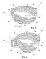
- FIG. 3is a view of another embodiment of the oblique magnetizer assembly in which the pole magnets are rotated about 60°.
- FIG. 4is a view of yet another embodiment of the oblique magnetizer assembly in which the pole magnets are rotated about 90°.
- FIG. 5is a view of still yet another embodiment of the oblique magnetizer assembly in which the pole magnets are rotated about 120°.
- FIG. 6is a view of yet another embodiment of the oblique magnetizer assembly in which the pole magnets are rotated about 150°.
- FIG. 7is an end view of another embodiment of the oblique magnetizer assembly, illustrating the relationship between the two ends of the spiraled or rotated pole magnets.
- the pole magnetsare rotated about 135°.
- the conformable upper surface of each pole magnetincludes a bristle or brush-type surface.
- FIG. 8illustrates field results from the oblique magnetizer arrangement.
- the field directionis diagonal, or oblique, to the longitudinal axis of the pipe.
- FIG. 9is a view of an embodiment of the oblique magnetizer assembly that includes a helical-shaped sensor array mounted from one end of the magnetizer to the other, providing complete coverage of the internal pipe wall surface and incorporating a degree of overlap to accommodate any tool rotation that may take place.
- FIG. 10is a view of the oblique magnetizer assembly of FIG. 8 encased in a pipe section.
- FIG. 11is a view of an inline inspection tool that includes the oblique magnetizer assembly, an axial magnetizer and a deformation sensing section.
- FIG. 12is a schematic illustrating one side of a sensor array that includes two lines or sets of EMAT sensor coils located between two oblique-oriented pole magnets.
- Each sensor coil setincludes two pairs of receiver coils and a transmitter coil located in-between the pairs of receiver coils.
- the setsare aligned perpendicular to the central longitudinal axis of the inline inspection tool (and, therefore, perpendicular to the central longitudinal axis of the tubular member being inspected) and each coil in the set shares a common centerline with the other coils in the set.
- FIG. 13is a view of one side of a sensor array having the EMAT sensor coil arrangement of FIG. 12 as applied to a 24 inch diameter tubular member.
- MFLmagnetic flux leakage
- a north pole magnet 41 and a south pole magnet 61are arranged about 180° opposite one another on a cylindrical tool body 21 so that the respective longitudinal centerline 47 , 67 of each pole magnet 41 , 61 is parallel to the longitudinal centerline 27 of the cylindrical tool body 21 (and therefore parallel to a central longitudinal axis of the pipe being inspected).
- pole magnets 41 , 61differ from prior art implementations in that, for example, each magnet 41 , 61 extends along the entire length of the cylindrical body 21 , their axial orientation as illustrated here is typical of prior art implementations.
- pole magnets 41 , 61generate a circumferential or transverse magnetic field relative to the pipe wall—as illustrated by magnetic flux paths 81 —and multiple magnetizer sections are required to provide complete coverage of the internal wall surface of the pipe.
- an oblique magnetizer assembly 20includes a magnetic circuit 40 that has two spiraled pole magnets 41 , 61 arranged about 180° opposite one another on cylindrical tool body 21 .
- Each pole magnet 41 , 61extends between a first end 23 and second end 25 of the cylindrical tool body 21 .
- Additional pairs of spiraled pole magnets 41 , 61may also be employed, with each spiraled pole magnet 41 or 61 extending between the ends 23 , 25 of cylindrical tool body 21 and spaced 360°/n from its adjacent and opposite pole magnet 61 , 41 (“n” being an equal to the number of pole magnets 41 , 61 employed).
- the pole magnets 41 , 61preferably have a flexible or conformable upper surface 49 , 69 , respectively, that helps reduce friction forces and minimize velocity effects as the oblique magnetizer assembly 20 travels through the interior of a pipe.
- the conformable upper surface 49 , 69also allows the magnetizer assembly 20 to compress a sufficient amount in order to pass by internal obstructions, bends, and reductions in the pipe that might otherwise damage the magnetizer assembly 20 or slow or prevent its passage.
- the rotation amount of the pole magnets 41 , 61depends on the amount of rotation required to achieve full coverage of the internal pipe wall surface. Going through the sequence from FIG. 2 to FIG. 6 , the pole magnets 41 , 61 are each rotated or spiraled in incremental amounts, for a nominal rotation of about 150 degrees (as illustrated in FIG. 6 ). When rotated, the second end 45 , 65 of the pole magnet 41 , 61 is offset by a predetermined angle or amount ⁇ relative to its respective first end 43 , 63 (see FIG. 7 ). Because of this rotation amount ⁇ , the respective longitudinal centerline 47 , 67 of each spiraled pole magnet 41 , 61 is non-parallel to the central longitudinal axis 27 of the cylindrical tool body 21 . The rotation of pole magnets 41 , 61 also helps induce a sufficient amount of rotation of magnetizer assembly 20 as it travels through the interior of the pipe.
- FIG. 8illustrates the magnetic field 80 generated from a prototype of oblique magnetizer assembly 20 , which was configured similar to the magnetizer assembly 20 shown in the rotation sequence of FIGS. 2 to 6 .
- the direction of magnetic field 80is diagonal or oblique to the pipe axis rather than circumferential or transverse, with magnetic flux paths 81 emanating from the poles 41 , 61 and traveling in opposite directions to reach a corresponding pole 61 , 41 .
- the magnetic flux lines 81 generated by each pole magnet 41 , 61are guided to the path of least resistance: into the pipe wall and toward the adjacent pole magnet 61 , 41 .
- the angle of the magnetic field 80is generally perpendicular to the flux lines 81 formed by the magnetic poles 41 , 61 and generally parallel to a line forming the shortest distance between the magnet poles 41 , 61 .
- the direction of magnetic field 80 within the extents of poles 41 , 61may range from 30 to 60 degrees relative to the pipe axis.
- oblique magnetizer assembly 20may include a helical-shaped sensor array 90 located substantially equidistant between rotated pole magnets 41 , 61 and arranged to provide complete coverage of the internal wall surface W of pipe P and accommodate any rotation of magnetizer assembly 20 that may take place.
- the individual sensors in sensor array 90may be of a kind well-known in the art for detecting magnetic flux leakage signals.
- Sensor array 90preferably extends between the first end 23 and second end 25 of cylindrical body 21 (and therefore between the respective ends 43 , 45 and 63 , 65 of pole magnets 41 , 61 ) and incorporates a degree of overlap ⁇ between a first end 91 and second end 93 of sensor array 90 .
- the conformable upper surfaces 49 , 69 of the pole magnets 41 , 61may be in the form of brushes 51 , 71 .
- Radial discs 31 A & Bhelp propel and center magnetizer assembly 20 as it moves forward in pipe P under differential pressure.
- the final configuration of oblique magnetizer assembly 20may include any current combination of data sets, including but not limited to deformation, high level axial MFL, internal/external discrimination, inertial data for mapping, and low level or residual MFL.
- the tool 10includes an axial magnetizer 100 and a deformation sensing section 110 (see FIG. 11 ).
- sensor array 90includes electro-magnetic acoustic transducers (EMAT) sensor coils 95 , 97 & 98 located between the opposing edges 42 , 62 of the oblique-oriented permanent pole magnets 41 , 61 .
- the sensor coils 95 , 97 & 98are preferably arranged in sensor coil lines or sets 94 a - e as defined by a respective sensor coil set central axis 99 a - e .
- Each central axis 99 a - eis generally parallel to the other axes 99 a - e and oriented at a predetermined angle ⁇ relative to the central longitudinal axis 27 of cylindrical tool body 21 .
- a substantially identical set of sensor coil sets (not shown) to sensor coil sets 94 a - eis arranged on the opposing external surface of cylindrical tool body 21 , about 180° opposite sensor coil sets 94 a - e.
- the oblique-oriented pole magnets 41 , 61are generally at an angle ⁇ relative to central longitudinal axis 27 , with angle ⁇ being different than angle ⁇ . Because the flux lines 81 generated by pole magnets 41 , 61 are generally perpendicular to the edges 42 , 62 of the pole magnets 41 , 61 , magnetic field 80 is rotated at an angles relative to the central longitudinal axis 21 and, therefore, is at an angle with respect to sensor coil sets 94 a - e . In a preferred embodiment, angle ⁇ is about 90°, angle ⁇ is about 45°, and angles ⁇ is about 45°.
- Arranging the sensor coil sets 94 a - e perpendicular to the central longitudinal axis 27 of cylindrical tool body 21 (and therefore perpendicular to the pipe axis)allows sensor array 90 to detect features in both the axial and circumferential directions.
- Transmitter coils 95generate SH waves 96 that travel circumferentially around the pipe and impinge at a normal angle (perpendicular) to axially oriented cracks.
- Arranging the sensor coil sets 94 a - e parallel to the central longitudinal axis 27 of the cylindrical tool body 21 (and therefore parallel to the pipe axis)allows sensor array 90 to detect features in the circumferential direction.
- Shear horizontal waves 96are transmitted along the pipe wall in the axial direction so that reflections from transverse cracks, such as cracks in girth welds, are detected.
- receiver coils 97 , 98do not have to be shifted diagonally with respect to, or rotated toward, the transmitter coil 95 in order to gain the benefits of having magnetic field 80 rotated with respect to the EMAT sensor coils 95 , 97 & 98 .
- Sensor coils 95 , 97 & 98may be mounted on a suitable mechanism such as a spring loaded pads (not shown) that keep the coils 95 , 97 & 98 in close proximity to the inside diameter of the pipe.
- the transmitter coils 95induce SH guided waves 96 in two circumferential directions around the pipe.
- the receiver coils 97detect reflections from stress corrosion cracks (SCC) and serve as the calibration receivers.
- Receiver coils 98detect the SH guided waves 96 that propagate from the transmitter coils 95 in the circumferential direction.
- the characteristic features of these detected signalssuch as amplitude and time of arrival, can be used to detect features such as coating disbond, corrosion and SCC.
- the receiver coils 97 , 98are placed at a predetermined distance from transmitter coil 95 so that signal responses are detected by receiver coils 97 , 98 but not affected adversely by the initial electronic excitation pulse.
- Each transmitter coil 95 in a set 94 a - eis grouped with two receiver coils 97 , 98 on each side.
- Sensor array 90preferably includes the requisite number of transmitter coils 95 and receiver coils 97 , 98 in order to provide overlapping coverage of SCC and coating disbond detection.
- each of two sensor arrays 90arranged opposite one another and for use in a 24-inch diameter pipe—included five transmitter coils 95 and 20 total receiver coils 97 , 98 .
- Each transmitter coil 95when fired causes SH guided waves 96 to propagate to both to the left and to the right of the coil 95 and around the circumference of the pipe.
- the receiver coils 97 , 98 closest to the active transmitter coil 95are first sampled in time (gated) to receive the outgoing waves 96 and then gated at a longer predetermined time delay, preferably on the order of 50 and 90 microseconds for a 24-inch diameter pipe, to detect reflections from SCC. These reflections are from targeted sampling zones “Z” located between the RD receiver coils 97 and a predetermined distance “D” past the RA receiver coils 98 so as to maximize coverage and minimize interference.
- the reflection signalsare normalized, i.e., divided by the outgoing signals detected in the RD receivers 97 to provide continuous calibration of the signal reflections.
- a pulse rate of 390 Hzwill yield an axial resolution of 5.1 mm (0.20 in.).
- This pulse rateallows the SH wave 96 to travel approximately 4.25 times around the pipe circumference before the second pulse or tone burst is fired. Consequently, the remnants of the first pulse are between the receiver coils 97 , 98 and therefore have no affect on the receiver coils 97 , 98 located on the opposite side of tool body 21 within that circumferential ring at the sampling time interval (gate).
- the SH waves 96are still within the receiver gates during the third tone burst, after the wave 96 has traveled about 8.5 times around the pipe.
- a tone burst transmitted at 100 percent full scalehas an amplitude of less than 0.3 percent when it arrives at the receiver coils 97 , 98 located on the opposite side of the cylindrical tool body 21 .
- This amount of noiseis usually negligible compared to other sources of noise, e.g., thermal electronic noise, which can be as much as 3 percent of full scale.
- Coating disbondis detected in the targeted sampling zones Z between RD receiver coils 97 and RA receiver coils 98 which are located in-line with the transmitter coils 95 .
- Coating disbond detectionmay be accomplished by computing the ratio of the gated receiver signals. Ratios that are above a set threshold indicate a lack of coating or disbond on the pipe in a particular zone 99 .
- Additional configurationsare possible, depending upon the pipe diameter, with differing numbers of pole magnets 41 , 61 , sensor coils 95 , 97 & 98 and sensor arrays 90 .
- the sensor array 90would be rotated at an oblique angle ⁇ relative to the pipe axis, still being located within the angular magnetic biasing field 80 .
- these configurationscould respond to features such as coating disbonds and metal loss.
- the resulting systemmay also be used as an EMAT-only system or combined with any of the various other technologies available in in-line inspection tools, including but not limited to MFL, Deformation, Caliper, and Mapping.
Landscapes
- Chemical & Material Sciences (AREA)
- Chemical Kinetics & Catalysis (AREA)
- Electrochemistry (AREA)
- Physics & Mathematics (AREA)
- Health & Medical Sciences (AREA)
- Life Sciences & Earth Sciences (AREA)
- Analytical Chemistry (AREA)
- Biochemistry (AREA)
- General Health & Medical Sciences (AREA)
- General Physics & Mathematics (AREA)
- Immunology (AREA)
- Pathology (AREA)
- Investigating Or Analyzing Materials By The Use Of Magnetic Means (AREA)
- Investigating Or Analyzing Materials By The Use Of Ultrasonic Waves (AREA)
- Geophysics And Detection Of Objects (AREA)
Abstract
Description
- 10 In-line inspection tool
- 20 MFL tool/oblique magnetizer
- 21 Cylindrical tool body
- 23 First end of21
- 25 Second end of21
- 27 Longitudinal axis of21
- 31 Radial disc
- 40 Magnetic circuit
- 41 Pole magnet
- 43 First end of41
- 45 Second end of41
- 47 Longitudinal centerline of41
- 49 Conformable upper surface
- 51 Brushes
- 61 Pole magnet
- 63 First end of61
- 65 Second end of61
- 67 Longitudinal centerline of61
- 69 Conformable upper surface
- 71 Brushes
- 80 Magnetic field
- 81 Magnetic flux path of
field 80 - 90 Sensor array
- 91 First end of90
- 93 Second end of90
- 94 Sensor coil line or set of95,97 &98
- 95 Transmitter coil
- 96 Shear horizontal wave generated by95
- 97 RD receiver coil
- 98 RA receiver coil
- 99 Central axis of sensor coil set94
- 100 Axial magnetizer
- 110 Deformation sensing section
- improved sensitivity to small defects, i.e., up to 20 db increase in signal amplitude;
- substantial decrease in RF pulser power requirements;
- full circumferential inspection coverage, reducing the probability of missing cracks;
- self-calibration of the transmitted signals using the receiver coils closest to transmitter coils; and
- less interference between transmitter coils caused by acoustic ring around.
Claims (21)
Priority Applications (12)
| Application Number | Priority Date | Filing Date | Title |
|---|---|---|---|
| US12/642,031US8319494B2 (en) | 2009-06-26 | 2009-12-18 | Pipeline inspection tool with double spiral EMAT sensor array |
| AT0102310AAT508478B1 (en) | 2009-06-26 | 2010-06-21 | SENSORARRAY FOR THE INSPECTION OF THE INTERNAL WALL OF A TUBE |
| GB1010491.7AGB2471386B (en) | 2009-06-26 | 2010-06-23 | Pipeline inspection tool with double spiral EMAT sensor array |
| NL2004962ANL2004962C2 (en) | 2009-06-26 | 2010-06-24 | Pipeline inspection tool with double spiral emat sensor array. |
| MYPI2010003006AMY178400A (en) | 2009-06-26 | 2010-06-24 | Pipeline inspection tool with sensor array |
| KR1020100060410AKR101729039B1 (en) | 2009-06-26 | 2010-06-25 | Pipeline Inspection Tool with Double Spiral EMAT Sensor Array |
| CA2708387ACA2708387C (en) | 2009-06-26 | 2010-06-25 | Pipeline inspection tool |
| CA2941509ACA2941509C (en) | 2009-06-26 | 2010-06-25 | Pipeline inspection tool |
| CN201010214796.2ACN101936949B (en) | 2009-06-26 | 2010-06-25 | Pipeline inspection tool with double spiral electromagnetic audio transducer (emat) sensor array |
| RU2010126189/28ARU2529655C2 (en) | 2009-06-26 | 2010-06-25 | Device of pipeline control with double spiral matrix of electromagnetoacoustic sensors |
| DE102010025064.3ADE102010025064B4 (en) | 2009-06-26 | 2010-06-25 | Pipeline inspection device with a double spiral EMUS sensor array |
| BRMU9001279-8UBRMU9001279U2 (en) | 2009-06-26 | 2010-06-28 | double spiral emat sensor assembly pipe inspection tool |
Applications Claiming Priority (3)
| Application Number | Priority Date | Filing Date | Title |
|---|---|---|---|
| US22073409P | 2009-06-26 | 2009-06-26 | |
| US23087909P | 2009-08-03 | 2009-08-03 | |
| US12/642,031US8319494B2 (en) | 2009-06-26 | 2009-12-18 | Pipeline inspection tool with double spiral EMAT sensor array |
Publications (2)
| Publication Number | Publication Date |
|---|---|
| US20100327858A1 US20100327858A1 (en) | 2010-12-30 |
| US8319494B2true US8319494B2 (en) | 2012-11-27 |
Family
ID=43379959
Family Applications (1)
| Application Number | Title | Priority Date | Filing Date |
|---|---|---|---|
| US12/642,031Active2031-07-22US8319494B2 (en) | 2009-06-26 | 2009-12-18 | Pipeline inspection tool with double spiral EMAT sensor array |
Country Status (2)
| Country | Link |
|---|---|
| US (1) | US8319494B2 (en) |
| RU (1) | RU2529655C2 (en) |
Cited By (7)
| Publication number | Priority date | Publication date | Assignee | Title |
|---|---|---|---|---|
| US20130068028A1 (en)* | 2008-08-08 | 2013-03-21 | Pure Technologies Ltd. | Pseudorandom binary sequence apparatus and method for in-line inspection tool |
| US20140312890A1 (en)* | 2011-12-30 | 2014-10-23 | Eni S.P.A. | Apparatus and method for monitoring the structural integrity of a pipeline by means of a superconducting magnet |
| US9201045B2 (en) | 2012-07-28 | 2015-12-01 | Itrobotics, Inc. | Internal and external universal EMAT inspection devices and related methods |
| EP3126628A4 (en)* | 2014-07-11 | 2017-11-22 | Halliburton Energy Services, Inc. | Focused symmetric pipe inspection tools |
| WO2018134771A1 (en)* | 2017-01-20 | 2018-07-26 | Novitech, Inc. | Magnetizers for pigging tools |
| US10520370B2 (en) | 2015-04-10 | 2019-12-31 | Indian Institute Of Technology Madras | Ultrasonic waveguide technique for distributed sensing and measurements of physical and chemical properties of surrounding media |
| US10866213B2 (en) | 2017-10-27 | 2020-12-15 | Zetec, Inc. | Eddy current probe |
Families Citing this family (11)
| Publication number | Priority date | Publication date | Assignee | Title |
|---|---|---|---|---|
| US7923994B2 (en)* | 2008-11-12 | 2011-04-12 | Hoyt Philip M | Spiral magnetic field apparatus and method for pipeline inspection |
| US8653811B2 (en)* | 2009-06-26 | 2014-02-18 | Tdw Delaware Inc. | Pipeline inspection tool with oblique magnetizer |
| US20120053895A1 (en)* | 2010-08-18 | 2012-03-01 | Noam Amir | Method and system for evaluating the condition of a collection of similar elongated hollow objects |
| US9153369B2 (en) | 2012-04-23 | 2015-10-06 | Infineon Technologies Ag | Bias field generator including a body having two body parts and holding a packaged magnetic sensor |
| RU2650621C1 (en)* | 2017-04-06 | 2018-04-16 | Публичное акционерное общество "Транснефть" (ПАО "Транснефть") | Method of inter-pipe diagnostics performance in a mobile liquid plug |
| CN107174202B (en)* | 2017-05-05 | 2020-08-04 | 深圳大学 | A method and system for magneto-acoustic imaging based on active detection |
| US20190094182A1 (en)* | 2017-09-22 | 2019-03-28 | KPL South Texas, LLC | System and method for analyzing anomalies in a conduit |
| WO2019123426A1 (en) | 2017-12-22 | 2019-06-27 | KPL South Texas, LLC | Valve gearbox cover systems and methods |
| WO2020208422A2 (en)* | 2019-04-11 | 2020-10-15 | Tdw Delaware, Inc. | Pipeline tool with composite magnetic field for inline inspection |
| JP2024512275A (en) | 2021-02-24 | 2024-03-19 | ビーダブリューエックスティー ニュークリア オペレーションズ グループ、インコーポレイテッド | Material inspection equipment and inspection method |
| CN113588774B (en)* | 2021-08-09 | 2023-08-15 | 中国石油大学(北京) | An In-pipeline Detector Combined with Acoustomagnetism |
Citations (61)
| Publication number | Priority date | Publication date | Assignee | Title |
|---|---|---|---|---|
| US2219708A (en)* | 1937-10-16 | 1940-10-29 | Bauer & Schaurte | Device for measuring lengths on an electromagnetic base |
| US3483466A (en)* | 1967-11-03 | 1969-12-09 | American Mach & Foundry | Pipeline inspection apparatus for detection of longitudinal defects |
| US3786684A (en)* | 1971-12-27 | 1974-01-22 | Automation Ind Inc | Pipeline inspection pig |
| US4330748A (en)* | 1979-03-16 | 1982-05-18 | British Gas Corporation | Frequency correction circuitry for pipeline sensor apparatus |
| JPS5958358A (en) | 1982-09-28 | 1984-04-04 | Mitsubishi Heavy Ind Ltd | Electromagnetic acoustic transducer |
| JPS6080760A (en) | 1983-10-11 | 1985-05-08 | Mitsubishi Heavy Ind Ltd | Electromagnetic ultrasonic transducer |
| JPS6267447A (en) | 1985-09-20 | 1987-03-27 | Mitsubishi Heavy Ind Ltd | Method and apparatus for detecting axial defect of tube |
| US4675604A (en)* | 1985-08-28 | 1987-06-23 | Exxon Production Research Co. | Computerized and motorized electromagnetic flux leakage internal diameter tubular inspection device |
| US4691572A (en) | 1984-08-09 | 1987-09-08 | Shell Oil Company | Transducing device for contactless ultrasonic inspection of pipelines or tubings |
| US4789827A (en)* | 1986-10-31 | 1988-12-06 | Electric Power Research Institute | Magnetic flux leakage probe with radially offset coils for use in nondestructive testing of pipes and tubes |
| US4797613A (en)* | 1985-01-22 | 1989-01-10 | Combustion Engineering, Inc. | Expandable eddy current probe for inspecting the interior of tubular conduits |
| US4851773A (en)* | 1981-09-28 | 1989-07-25 | Samuel Rothstein | Rotating head profilometer probe |
| US4857851A (en)* | 1981-09-23 | 1989-08-15 | British Gas Corporation | Fixing a geographical reference of a vehicle traveling through a pipeline |
| US4893077A (en)* | 1987-05-28 | 1990-01-09 | Auchterlonie Richard C | Absolute position sensor having multi-layer windings of different pitches providing respective indications of phase proportional to displacement |
| US4909091A (en)* | 1986-11-14 | 1990-03-20 | Kernforschungszentrum Karlsruhe Gmbh | Method and apparatus for the detection of corrosion or the like |
| US4952875A (en)* | 1988-06-15 | 1990-08-28 | Siemens Aktiengesellschaft | Eddy current probe with recesses to hold coils and allow the coils to rock and move perpendicular to the longitudinal axis of the probe |
| US5233297A (en)* | 1990-08-06 | 1993-08-03 | Atlantic Richfield Company | Transient electromagnetic method and apparatus for inspecting conductive objects utilizing sensors that move during inspection |
| US5256966A (en)* | 1991-04-19 | 1993-10-26 | Combustion Engineering, Inc. | Method for detecting flaws in a steam generator tube using a flexible eddy current probe having coil bank switching |
| US5419206A (en)* | 1991-11-05 | 1995-05-30 | Japan Electronic Control Systems Co., Ltd. | Phase independent torque detection and processing circuit for sensing device |
| US5454276A (en) | 1993-07-30 | 1995-10-03 | Wernicke; Timothy K. | Multi-directional magnetic flux pipe inspection apparatus and method |
| US5532587A (en)* | 1991-12-16 | 1996-07-02 | Vetco Pipeline Services, Inc. | Magnetic field analysis method and apparatus for determining stress characteristics in a pipeline |
| US5565633A (en) | 1993-07-30 | 1996-10-15 | Wernicke; Timothy K. | Spiral tractor apparatus and method |
| US5574223A (en)* | 1994-04-05 | 1996-11-12 | Gas Research Institute | Scan assembly and method using scan rate modulation |
| US5581037A (en)* | 1992-11-06 | 1996-12-03 | Southwest Research Institute | Nondestructive evaluation of pipes and tubes using magnetostrictive sensors |
| US5619423A (en) | 1994-01-21 | 1997-04-08 | Scrantz; Leonard | System, method and apparatus for the ultrasonic inspection of liquid filled tubulars and vessels |
| US5777469A (en)* | 1995-07-31 | 1998-07-07 | Battelle Memorial Institute | Method and apparatus for detecting flaws in conductive material |
| US6009756A (en) | 1995-11-22 | 2000-01-04 | Pipetronix Bmbh | Device for testing ferromagnetic materials |
| US6087830A (en)* | 1994-07-07 | 2000-07-11 | Hydroscope Canada Inc. | Flexible device for remote field eddy current inspection of ferrous pipeline containing turns |
| US6100684A (en)* | 1997-04-21 | 2000-08-08 | Societe Des Transports Petroliers Par Pipeline Trapil | Helically traveling non-destructive system for the detection of cracks in pipelines |
| US6404189B2 (en) | 1999-03-17 | 2002-06-11 | Southeast Research Institute | Method and apparatus for inspecting pipelines from an in-line inspection vehicle using magnetostrictive probes |
| US6456066B1 (en)* | 1997-09-06 | 2002-09-24 | Lattice Intellectual Property Limited | Eddy current pipeline inspection device and method |
| US6628118B1 (en)* | 1999-11-20 | 2003-09-30 | Em-Tech Sensors Llc | Method and apparatus for control of magnetic flux direction and concentration |
| US20040095137A1 (en) | 1999-03-17 | 2004-05-20 | Hegeon Kwun | Method and apparatus generating and detecting torsional wave inspection of pipes or tubes |
| US20040207395A1 (en)* | 2002-04-08 | 2004-10-21 | Moshe Sarfaty | Eddy current-capacitance sensor for conducting film characterization |
| US20040217759A1 (en)* | 2003-04-21 | 2004-11-04 | Burkhardt Gary L | System and Method for Inspection of Pipelines Having Internal Restrictions |
| US20040221652A1 (en) | 2003-05-05 | 2004-11-11 | Flora John H. | Transducer guided wave electromagnetic acoustic |
| US6820653B1 (en) | 1999-04-12 | 2004-11-23 | Carnegie Mellon University | Pipe inspection and repair system |
| US20040232909A1 (en)* | 2001-09-25 | 2004-11-25 | Kazunobu Imamoto | Non-destructive inspection device and non-destructive inspection method |
| US20050072237A1 (en) | 2001-09-05 | 2005-04-07 | David Paige | Pipeline inspection pigs |
| US6967726B2 (en)* | 2003-10-03 | 2005-11-22 | Honeywell International Inc. | Means for in-place automated calibration of optically-based thickness sensor |
| US6975120B2 (en)* | 2001-04-21 | 2005-12-13 | Amini Bijan K | Measurement of subterranean lithology using electromagnetic energy |
| US20060027022A1 (en)* | 2004-07-23 | 2006-02-09 | Electric Power Research Institute, Inc. | Flexible electromagnetic acoustic transducer sensor |
| WO2006048290A1 (en) | 2004-11-05 | 2006-05-11 | Fraunhofer-Gesellschaft zur Förderung der angewandten Forschung e.V | Device and method for the electromagnetic, acoustic material testing and/or thickness measurement of a test object that contains at least electrically conductive and ferromagnetic material fractions |
| WO2006069684A1 (en) | 2004-12-23 | 2006-07-06 | Rosen Swiss Ag | Device for testing ferromagnetic component walls without destruction of the same |
| US20060158181A1 (en)* | 2003-09-18 | 2006-07-20 | Tdk Corporation | Eddy-current probe |
| US7143659B2 (en)* | 2002-12-17 | 2006-12-05 | Pinnacle West Capital Corporation | Pipe-inspection system |
| US7256576B2 (en)* | 2005-07-29 | 2007-08-14 | General Electric Company | ID-OD discrimination sensor |
| US20070222436A1 (en) | 2006-03-27 | 2007-09-27 | General Electric Company | Method and apparatus inspecting pipelines using magnetic flux sensors |
| US20070229066A1 (en)* | 2006-03-03 | 2007-10-04 | Soshi Narishige | Eddy current flaw detection sensor and method |
| US7356421B2 (en)* | 2004-07-29 | 2008-04-08 | Metrotech Corporation, Inc. | Precise location of buried metallic pipes and cables in the presence of signal distortion |
| US20080092672A1 (en) | 2004-06-03 | 2008-04-24 | Michael Gibson | In-Line Pipe Inspection Tool |
| US20080215257A1 (en) | 2005-02-05 | 2008-09-04 | Forschungszentrum Karlsruhe Gmbh | Method for Reducing Digital Data in an Emat Pig |
| US20090139337A1 (en) | 2007-12-03 | 2009-06-04 | Fbs, Inc. | Guided wave pipeline inspection system and method with enhanced natural focusing techniques |
| DE102007058043A1 (en) | 2007-11-30 | 2009-06-04 | Rosen Swiss Ag | Self-propelled pipeline inspection unit follows a spiral path through the pipeline, with a measuring unit to test its condition without damage |
| US7548059B2 (en) | 2005-04-01 | 2009-06-16 | Intratech Inline Inspection Services Ltd. | Pipeline inspection tool with spirally arranged sensor blocks |
| US20090158850A1 (en) | 2006-04-28 | 2009-06-25 | David Alleyne | Method and apparatus for ultrasonically inspecting pipes |
| US20090193899A1 (en) | 2008-02-25 | 2009-08-06 | Battelle Memorial Institute | System and process for ultrasonic characterization of deformed structures |
| US7683611B2 (en)* | 2006-06-23 | 2010-03-23 | Southwest Research Institute | Pipeline inspection using variable-diameter remote-field eddy current technology |
| US20100117635A1 (en) | 2008-11-12 | 2010-05-13 | Hoyt Philip M | Spiral magnetic field apparatus and method for pipeline inspection |
| US20100199767A1 (en) | 2009-02-09 | 2010-08-12 | Weatherford/Lamb | In-line inspection tool for pipeline integrity testing |
| US7782048B2 (en)* | 2006-12-26 | 2010-08-24 | Sumitomo Metal Industries, Ltd. | Eddy current testing method, eddy current testing differential coil and eddy current testing probe for internal finned pipe or tube |
Family Cites Families (5)
| Publication number | Priority date | Publication date | Assignee | Title |
|---|---|---|---|---|
| SU1296923A1 (en)* | 1985-07-02 | 1987-03-15 | Московский энергетический институт | Eddy-current transducer |
| US5115196A (en)* | 1988-06-01 | 1992-05-19 | Atlantic Richfield Company | Girth weld detection system for pipeline survey pig |
| US5864232A (en)* | 1996-08-22 | 1999-01-26 | Pipetronix, Ltd. | Magnetic flux pipe inspection apparatus for analyzing anomalies in a pipeline wall |
| CN100434914C (en)* | 2004-02-10 | 2008-11-19 | 何辅云 | Method and device for detecting large-diameter steel pipes without blind spots without changing probes |
| WO2009061745A2 (en)* | 2007-11-05 | 2009-05-14 | Energy Enzymes, Inc. | Process of producing ethanol using starch with enzymes generated through solid state culture |
- 2009
- 2009-12-18USUS12/642,031patent/US8319494B2/enactiveActive
- 2010
- 2010-06-25RURU2010126189/28Apatent/RU2529655C2/enactive
Patent Citations (66)
| Publication number | Priority date | Publication date | Assignee | Title |
|---|---|---|---|---|
| US2219708A (en)* | 1937-10-16 | 1940-10-29 | Bauer & Schaurte | Device for measuring lengths on an electromagnetic base |
| US3483466A (en)* | 1967-11-03 | 1969-12-09 | American Mach & Foundry | Pipeline inspection apparatus for detection of longitudinal defects |
| US3786684A (en)* | 1971-12-27 | 1974-01-22 | Automation Ind Inc | Pipeline inspection pig |
| US4330748A (en)* | 1979-03-16 | 1982-05-18 | British Gas Corporation | Frequency correction circuitry for pipeline sensor apparatus |
| US4857851A (en)* | 1981-09-23 | 1989-08-15 | British Gas Corporation | Fixing a geographical reference of a vehicle traveling through a pipeline |
| US4851773A (en)* | 1981-09-28 | 1989-07-25 | Samuel Rothstein | Rotating head profilometer probe |
| JPS5958358A (en) | 1982-09-28 | 1984-04-04 | Mitsubishi Heavy Ind Ltd | Electromagnetic acoustic transducer |
| JPS6080760A (en) | 1983-10-11 | 1985-05-08 | Mitsubishi Heavy Ind Ltd | Electromagnetic ultrasonic transducer |
| US4691572A (en) | 1984-08-09 | 1987-09-08 | Shell Oil Company | Transducing device for contactless ultrasonic inspection of pipelines or tubings |
| US4797613A (en)* | 1985-01-22 | 1989-01-10 | Combustion Engineering, Inc. | Expandable eddy current probe for inspecting the interior of tubular conduits |
| US4675604A (en)* | 1985-08-28 | 1987-06-23 | Exxon Production Research Co. | Computerized and motorized electromagnetic flux leakage internal diameter tubular inspection device |
| JPS6267447A (en) | 1985-09-20 | 1987-03-27 | Mitsubishi Heavy Ind Ltd | Method and apparatus for detecting axial defect of tube |
| US4789827A (en)* | 1986-10-31 | 1988-12-06 | Electric Power Research Institute | Magnetic flux leakage probe with radially offset coils for use in nondestructive testing of pipes and tubes |
| US4909091A (en)* | 1986-11-14 | 1990-03-20 | Kernforschungszentrum Karlsruhe Gmbh | Method and apparatus for the detection of corrosion or the like |
| US4893077A (en)* | 1987-05-28 | 1990-01-09 | Auchterlonie Richard C | Absolute position sensor having multi-layer windings of different pitches providing respective indications of phase proportional to displacement |
| US4952875A (en)* | 1988-06-15 | 1990-08-28 | Siemens Aktiengesellschaft | Eddy current probe with recesses to hold coils and allow the coils to rock and move perpendicular to the longitudinal axis of the probe |
| US5233297A (en)* | 1990-08-06 | 1993-08-03 | Atlantic Richfield Company | Transient electromagnetic method and apparatus for inspecting conductive objects utilizing sensors that move during inspection |
| US5256966A (en)* | 1991-04-19 | 1993-10-26 | Combustion Engineering, Inc. | Method for detecting flaws in a steam generator tube using a flexible eddy current probe having coil bank switching |
| US5419206A (en)* | 1991-11-05 | 1995-05-30 | Japan Electronic Control Systems Co., Ltd. | Phase independent torque detection and processing circuit for sensing device |
| US5532587A (en)* | 1991-12-16 | 1996-07-02 | Vetco Pipeline Services, Inc. | Magnetic field analysis method and apparatus for determining stress characteristics in a pipeline |
| US5581037A (en)* | 1992-11-06 | 1996-12-03 | Southwest Research Institute | Nondestructive evaluation of pipes and tubes using magnetostrictive sensors |
| US5454276A (en) | 1993-07-30 | 1995-10-03 | Wernicke; Timothy K. | Multi-directional magnetic flux pipe inspection apparatus and method |
| US5565633A (en) | 1993-07-30 | 1996-10-15 | Wernicke; Timothy K. | Spiral tractor apparatus and method |
| US5619423A (en) | 1994-01-21 | 1997-04-08 | Scrantz; Leonard | System, method and apparatus for the ultrasonic inspection of liquid filled tubulars and vessels |
| US5574223A (en)* | 1994-04-05 | 1996-11-12 | Gas Research Institute | Scan assembly and method using scan rate modulation |
| US6087830A (en)* | 1994-07-07 | 2000-07-11 | Hydroscope Canada Inc. | Flexible device for remote field eddy current inspection of ferrous pipeline containing turns |
| US5777469A (en)* | 1995-07-31 | 1998-07-07 | Battelle Memorial Institute | Method and apparatus for detecting flaws in conductive material |
| US6009756A (en) | 1995-11-22 | 2000-01-04 | Pipetronix Bmbh | Device for testing ferromagnetic materials |
| US6100684A (en)* | 1997-04-21 | 2000-08-08 | Societe Des Transports Petroliers Par Pipeline Trapil | Helically traveling non-destructive system for the detection of cracks in pipelines |
| US6456066B1 (en)* | 1997-09-06 | 2002-09-24 | Lattice Intellectual Property Limited | Eddy current pipeline inspection device and method |
| US6404189B2 (en) | 1999-03-17 | 2002-06-11 | Southeast Research Institute | Method and apparatus for inspecting pipelines from an in-line inspection vehicle using magnetostrictive probes |
| US20040095137A1 (en) | 1999-03-17 | 2004-05-20 | Hegeon Kwun | Method and apparatus generating and detecting torsional wave inspection of pipes or tubes |
| US6820653B1 (en) | 1999-04-12 | 2004-11-23 | Carnegie Mellon University | Pipe inspection and repair system |
| US6628118B1 (en)* | 1999-11-20 | 2003-09-30 | Em-Tech Sensors Llc | Method and apparatus for control of magnetic flux direction and concentration |
| US6975120B2 (en)* | 2001-04-21 | 2005-12-13 | Amini Bijan K | Measurement of subterranean lithology using electromagnetic energy |
| US20050072237A1 (en) | 2001-09-05 | 2005-04-07 | David Paige | Pipeline inspection pigs |
| US7084623B2 (en)* | 2001-09-25 | 2006-08-01 | Daihatsu Motor Co., Ltd. | Non-destructive inspection device and method utilizing a magnetic field and sensor coil array |
| US20040232909A1 (en)* | 2001-09-25 | 2004-11-25 | Kazunobu Imamoto | Non-destructive inspection device and non-destructive inspection method |
| US20040207395A1 (en)* | 2002-04-08 | 2004-10-21 | Moshe Sarfaty | Eddy current-capacitance sensor for conducting film characterization |
| US7143659B2 (en)* | 2002-12-17 | 2006-12-05 | Pinnacle West Capital Corporation | Pipe-inspection system |
| US20040217759A1 (en)* | 2003-04-21 | 2004-11-04 | Burkhardt Gary L | System and Method for Inspection of Pipelines Having Internal Restrictions |
| US20040221652A1 (en) | 2003-05-05 | 2004-11-11 | Flora John H. | Transducer guided wave electromagnetic acoustic |
| US20060158181A1 (en)* | 2003-09-18 | 2006-07-20 | Tdk Corporation | Eddy-current probe |
| US6967726B2 (en)* | 2003-10-03 | 2005-11-22 | Honeywell International Inc. | Means for in-place automated calibration of optically-based thickness sensor |
| US20080092672A1 (en) | 2004-06-03 | 2008-04-24 | Michael Gibson | In-Line Pipe Inspection Tool |
| US20060027022A1 (en)* | 2004-07-23 | 2006-02-09 | Electric Power Research Institute, Inc. | Flexible electromagnetic acoustic transducer sensor |
| US7356421B2 (en)* | 2004-07-29 | 2008-04-08 | Metrotech Corporation, Inc. | Precise location of buried metallic pipes and cables in the presence of signal distortion |
| WO2006048290A1 (en) | 2004-11-05 | 2006-05-11 | Fraunhofer-Gesellschaft zur Förderung der angewandten Forschung e.V | Device and method for the electromagnetic, acoustic material testing and/or thickness measurement of a test object that contains at least electrically conductive and ferromagnetic material fractions |
| CA2592094A1 (en) | 2004-12-23 | 2006-07-06 | Rosen Swiss Ag | Device for testing ferromagnetic component walls without destruction of the same |
| WO2006069684A1 (en) | 2004-12-23 | 2006-07-06 | Rosen Swiss Ag | Device for testing ferromagnetic component walls without destruction of the same |
| US20090078048A1 (en) | 2004-12-23 | 2009-03-26 | Rosen Swiss Ag | Device for Testing Ferromagnetic Component Walls without Destruction of the Same |
| US20080215257A1 (en) | 2005-02-05 | 2008-09-04 | Forschungszentrum Karlsruhe Gmbh | Method for Reducing Digital Data in an Emat Pig |
| US7548059B2 (en) | 2005-04-01 | 2009-06-16 | Intratech Inline Inspection Services Ltd. | Pipeline inspection tool with spirally arranged sensor blocks |
| US7256576B2 (en)* | 2005-07-29 | 2007-08-14 | General Electric Company | ID-OD discrimination sensor |
| US20070229066A1 (en)* | 2006-03-03 | 2007-10-04 | Soshi Narishige | Eddy current flaw detection sensor and method |
| US7358721B2 (en)* | 2006-03-03 | 2008-04-15 | Hitachi, Ltd. | Eddy current flaw detection sensor and method |
| US20070222436A1 (en) | 2006-03-27 | 2007-09-27 | General Electric Company | Method and apparatus inspecting pipelines using magnetic flux sensors |
| US20090158850A1 (en) | 2006-04-28 | 2009-06-25 | David Alleyne | Method and apparatus for ultrasonically inspecting pipes |
| US7683611B2 (en)* | 2006-06-23 | 2010-03-23 | Southwest Research Institute | Pipeline inspection using variable-diameter remote-field eddy current technology |
| US7782048B2 (en)* | 2006-12-26 | 2010-08-24 | Sumitomo Metal Industries, Ltd. | Eddy current testing method, eddy current testing differential coil and eddy current testing probe for internal finned pipe or tube |
| DE102007058043A1 (en) | 2007-11-30 | 2009-06-04 | Rosen Swiss Ag | Self-propelled pipeline inspection unit follows a spiral path through the pipeline, with a measuring unit to test its condition without damage |
| US20090139337A1 (en) | 2007-12-03 | 2009-06-04 | Fbs, Inc. | Guided wave pipeline inspection system and method with enhanced natural focusing techniques |
| US20090193899A1 (en) | 2008-02-25 | 2009-08-06 | Battelle Memorial Institute | System and process for ultrasonic characterization of deformed structures |
| US20100117635A1 (en) | 2008-11-12 | 2010-05-13 | Hoyt Philip M | Spiral magnetic field apparatus and method for pipeline inspection |
| US8089273B2 (en)* | 2008-11-12 | 2012-01-03 | Hoyt Philip M | Spiral magnetic field apparatus and method for pipeline inspection |
| US20100199767A1 (en) | 2009-02-09 | 2010-08-12 | Weatherford/Lamb | In-line inspection tool for pipeline integrity testing |
Non-Patent Citations (8)
| Title |
|---|
| Austrian Patent Office, "First Office Action issued by the Austrian Patent Office dated Feb. 25, 2011 in Patent Application No. 10222010,". |
| Netherlands Patent Office, "Search Report issued by the Netherlands Patent Office dated Dec. 16, 2010 in Patent Application No. 2004962,". |
| Search Report issued by the United Kingdom Intellectual Property Office dated Aug. 10, 2010 in application GB1010491.7 (2 pgs). |
| Search Report issued by the United Kingdom Intellectual Property Office dated Aug. 25, 2010 in application GB1010493.3 (1 pg). |
| Simek et al., "In-Line Inspection EMAT Utilizing an Oblique Field", International NACE Corrosion Conference & EXPO 2012, pp. 1-9.* |
| Simek, "Oblique Field Magnetic Flux Leakage Survey Complements Axial Field Data", International NACE Corrosion Conference & EXPO 2011, pp. 1-9.* |
| Van Den Berg et al., "Development of an Electromagnetic Acoustic Transducer for Inspecting the Wall Thickness of Offshore Risers From the Inside, 1988,". |
| Wiley, "Borehole Televiewer-Revisited", SPWLA Twenty-First Annual Logging Symposium, Jul. 8-11, 1980, pp. 1-16.* |
Cited By (11)
| Publication number | Priority date | Publication date | Assignee | Title |
|---|---|---|---|---|
| US20130068028A1 (en)* | 2008-08-08 | 2013-03-21 | Pure Technologies Ltd. | Pseudorandom binary sequence apparatus and method for in-line inspection tool |
| US8631705B2 (en)* | 2008-08-08 | 2014-01-21 | Pure Technologies Ltd. | Pseudorandom binary sequence apparatus and method for in-line inspection tool |
| US20140312890A1 (en)* | 2011-12-30 | 2014-10-23 | Eni S.P.A. | Apparatus and method for monitoring the structural integrity of a pipeline by means of a superconducting magnet |
| US9535037B2 (en)* | 2011-12-30 | 2017-01-03 | Eni S.P.A. | Apparatus and method for monitoring the structural integrity of a pipeline by means of a superconducting magnet |
| US9201045B2 (en) | 2012-07-28 | 2015-12-01 | Itrobotics, Inc. | Internal and external universal EMAT inspection devices and related methods |
| EP3126628A4 (en)* | 2014-07-11 | 2017-11-22 | Halliburton Energy Services, Inc. | Focused symmetric pipe inspection tools |
| US10613244B2 (en) | 2014-07-11 | 2020-04-07 | Halliburton Energy Services, Inc. | Focused symmetric pipe inspection tools |
| US10520370B2 (en) | 2015-04-10 | 2019-12-31 | Indian Institute Of Technology Madras | Ultrasonic waveguide technique for distributed sensing and measurements of physical and chemical properties of surrounding media |
| US11022502B2 (en)* | 2015-04-10 | 2021-06-01 | Indian Institute Of Technology Madras | Ultrasonic waveguide technique for distribute sensing and measurements of physical and chemical properties of surrounding media |
| WO2018134771A1 (en)* | 2017-01-20 | 2018-07-26 | Novitech, Inc. | Magnetizers for pigging tools |
| US10866213B2 (en) | 2017-10-27 | 2020-12-15 | Zetec, Inc. | Eddy current probe |
Also Published As
| Publication number | Publication date |
|---|---|
| RU2010126189A (en) | 2011-12-27 |
| US20100327858A1 (en) | 2010-12-30 |
| RU2529655C2 (en) | 2014-09-27 |
Similar Documents
| Publication | Publication Date | Title |
|---|---|---|
| US8319494B2 (en) | Pipeline inspection tool with double spiral EMAT sensor array | |
| NL2004962C2 (en) | Pipeline inspection tool with double spiral emat sensor array. | |
| US7997139B2 (en) | Guided wave pipeline inspection system and method with enhanced natural focusing techniques | |
| US8631705B2 (en) | Pseudorandom binary sequence apparatus and method for in-line inspection tool | |
| US8170809B2 (en) | Guided waves for nondestructive testing of pipes | |
| USRE40515E1 (en) | Method and apparatus for inspecting pipelines from an in-line inspection vehicle using magnetostrictive probes | |
| JP3669706B2 (en) | Nondestructive evaluation of pipes and tubes using magnetostrictive sensors | |
| Alleyne et al. | The long range detection of corrosion in pipes using Lamb waves | |
| CN108226277A (en) | A composite pipeline external detection probe of magnetic flux leakage, electromagnetic ultrasonic and eddy current | |
| NL2004963C2 (en) | Pipeline inspection tool with oblique magnetizer. | |
| GB2471386A (en) | Pipeline inspection tool with double spiral EMAT sensor array | |
| JP5127574B2 (en) | Inspection method using guide waves | |
| Gori et al. | Guided waves by EMAT transducers for rapid defect location on heat exchanger and boiler tubes | |
| Park et al. | Development of EMA transducer for inspection of pipelines | |
| JP2000321041A (en) | Method for detecting carburized layer and method for measuring its thickness | |
| RU2790942C1 (en) | Pipeline monitoring device using electromagnetic acoustic technology | |
| RU2794338C2 (en) | Method for pipeline control using electromagnetic-acoustic technology | |
| Berndt | NON-DESTRUCTIVE TESTING METHODS FOR GEOTHERMAL PIPING. | |
| Shrestha et al. | In-Line Inspection EMAT Utilizing an Oblique Field | |
| US10352909B2 (en) | Paired magnetostrictive transducers for non destructive testing of tubular structures with selective torsional or flexural wave modes | |
| Nestleroth | Implementing current in-line inspection technologies on crawler systems | |
| Bertoncini et al. | 3D characterization of defects in Guided Wave monitoring of pipework using a magnetostrictive sensor | |
| Imagawa et al. | Ultrasonic guided wave testing system for piping | |
| JPH04340462A (en) | Insert type eddy current flaw detector for magnetic pipe |
Legal Events
| Date | Code | Title | Description |
|---|---|---|---|
| AS | Assignment | Owner name:TDW DELAWARE, INC., DELAWARE Free format text:ASSIGNMENT OF ASSIGNORS INTEREST;ASSIGNORS:SIMEK, JAMES;LUDLOW, JED;FLORA, JOHN H.;AND OTHERS;REEL/FRAME:023694/0559 Effective date:20090820 | |
| STCF | Information on status: patent grant | Free format text:PATENTED CASE | |
| FPAY | Fee payment | Year of fee payment:4 | |
| AS | Assignment | Owner name:JPMORGAN CHASE BANK, N.A., OKLAHOMA Free format text:SECURITY AGREEMENT;ASSIGNOR:TDW DELAWARE, INC.;REEL/FRAME:038890/0574 Effective date:20160526 | |
| MAFP | Maintenance fee payment | Free format text:PAYMENT OF MAINTENANCE FEE, 8TH YEAR, LARGE ENTITY (ORIGINAL EVENT CODE: M1552); ENTITY STATUS OF PATENT OWNER: LARGE ENTITY Year of fee payment:8 | |
| AS | Assignment | Owner name:JPMORGAN CHASE BANK, N.A., AS ADMINISTRATIVE ASSISTANT, ILLINOIS Free format text:SECURITY INTEREST;ASSIGNOR:TDW DELAWARE, INC.;REEL/FRAME:052900/0932 Effective date:20200610 | |
| AS | Assignment | Owner name:TDW DELAWARE, INC., OKLAHOMA Free format text:RELEASE BY SECURED PARTY;ASSIGNOR:JPMORGAN CHASE BANK, N.A.;REEL/FRAME:061002/0552 Effective date:20220630 Owner name:TDW DELAWARE, INC., OKLAHOMA Free format text:RELEASE BY SECURED PARTY;ASSIGNOR:JPMORGAN CHASE BANK, N.A.;REEL/FRAME:060655/0561 Effective date:20220630 | |
| AS | Assignment | Owner name:CADENCE BANK, TEXAS Free format text:SECURITY INTEREST;ASSIGNOR:TDW DELAWARE, INC.;REEL/FRAME:061147/0932 Effective date:20220630 | |
| MAFP | Maintenance fee payment | Free format text:PAYMENT OF MAINTENANCE FEE, 12TH YEAR, LARGE ENTITY (ORIGINAL EVENT CODE: M1553); ENTITY STATUS OF PATENT OWNER: LARGE ENTITY Year of fee payment:12 |