US8317870B2 - Tibial component of a knee prosthesis having an angled cement pocket - Google Patents
Tibial component of a knee prosthesis having an angled cement pocketDownload PDFInfo
- Publication number
- US8317870B2 US8317870B2US13/249,496US201113249496AUS8317870B2US 8317870 B2US8317870 B2US 8317870B2US 201113249496 AUS201113249496 AUS 201113249496AUS 8317870 B2US8317870 B2US 8317870B2
- Authority
- US
- United States
- Prior art keywords
- tibial
- knee prosthesis
- component
- inferior
- sidewall
- Prior art date
- Legal status (The legal status is an assumption and is not a legal conclusion. Google has not performed a legal analysis and makes no representation as to the accuracy of the status listed.)
- Expired - Fee Related
Links
- 239000004568cementSubstances0.000titleclaimsabstractdescription120
- 210000003127kneeAnatomy0.000titleclaimsabstractdescription42
- 230000002093peripheral effectEffects0.000claimsdescription21
- 230000001154acute effectEffects0.000claimsdescription13
- 210000002303tibiaAnatomy0.000claimsdescription11
- 210000000988bone and boneAnatomy0.000abstractdescription6
- 239000002639bone cementSubstances0.000description25
- 210000000689upper legAnatomy0.000description16
- 238000000034methodMethods0.000description6
- 239000007943implantSubstances0.000description4
- 239000000463materialSubstances0.000description4
- 238000001356surgical procedureMethods0.000description4
- 230000008901benefitEffects0.000description3
- 238000012986modificationMethods0.000description3
- 230000004048modificationEffects0.000description3
- 230000007704transitionEffects0.000description3
- 210000003484anatomyAnatomy0.000description2
- 230000000295complement effectEffects0.000description2
- 229910000684Cobalt-chromeInorganic materials0.000description1
- 239000004698PolyethyleneSubstances0.000description1
- 229920010741Ultra High Molecular Weight Polyethylene (UHMWPE)Polymers0.000description1
- 229910045601alloyInorganic materials0.000description1
- 239000000956alloySubstances0.000description1
- 229920000249biocompatible polymerPolymers0.000description1
- 239000000919ceramicSubstances0.000description1
- 239000010952cobalt-chromeSubstances0.000description1
- 201000010099diseaseDiseases0.000description1
- 208000037265diseases, disorders, signs and symptomsDiseases0.000description1
- 238000002513implantationMethods0.000description1
- 208000014674injuryDiseases0.000description1
- 238000013150knee replacementMethods0.000description1
- 239000002184metalSubstances0.000description1
- 229910052751metalInorganic materials0.000description1
- -1polyethylenePolymers0.000description1
- 229920000573polyethylenePolymers0.000description1
- 230000036316preloadEffects0.000description1
- 230000008733traumaEffects0.000description1
Images


Classifications
- A—HUMAN NECESSITIES
- A61—MEDICAL OR VETERINARY SCIENCE; HYGIENE
- A61F—FILTERS IMPLANTABLE INTO BLOOD VESSELS; PROSTHESES; DEVICES PROVIDING PATENCY TO, OR PREVENTING COLLAPSING OF, TUBULAR STRUCTURES OF THE BODY, e.g. STENTS; ORTHOPAEDIC, NURSING OR CONTRACEPTIVE DEVICES; FOMENTATION; TREATMENT OR PROTECTION OF EYES OR EARS; BANDAGES, DRESSINGS OR ABSORBENT PADS; FIRST-AID KITS
- A61F2/00—Filters implantable into blood vessels; Prostheses, i.e. artificial substitutes or replacements for parts of the body; Appliances for connecting them with the body; Devices providing patency to, or preventing collapsing of, tubular structures of the body, e.g. stents
- A61F2/02—Prostheses implantable into the body
- A61F2/30—Joints
- A61F2/38—Joints for elbows or knees
- A61F2/3859—Femoral components
- A—HUMAN NECESSITIES
- A61—MEDICAL OR VETERINARY SCIENCE; HYGIENE
- A61F—FILTERS IMPLANTABLE INTO BLOOD VESSELS; PROSTHESES; DEVICES PROVIDING PATENCY TO, OR PREVENTING COLLAPSING OF, TUBULAR STRUCTURES OF THE BODY, e.g. STENTS; ORTHOPAEDIC, NURSING OR CONTRACEPTIVE DEVICES; FOMENTATION; TREATMENT OR PROTECTION OF EYES OR EARS; BANDAGES, DRESSINGS OR ABSORBENT PADS; FIRST-AID KITS
- A61F2/00—Filters implantable into blood vessels; Prostheses, i.e. artificial substitutes or replacements for parts of the body; Appliances for connecting them with the body; Devices providing patency to, or preventing collapsing of, tubular structures of the body, e.g. stents
- A61F2/02—Prostheses implantable into the body
- A61F2/30—Joints
- A61F2/38—Joints for elbows or knees
- A61F2/3836—Special connection between upper and lower leg, e.g. constrained
- A—HUMAN NECESSITIES
- A61—MEDICAL OR VETERINARY SCIENCE; HYGIENE
- A61F—FILTERS IMPLANTABLE INTO BLOOD VESSELS; PROSTHESES; DEVICES PROVIDING PATENCY TO, OR PREVENTING COLLAPSING OF, TUBULAR STRUCTURES OF THE BODY, e.g. STENTS; ORTHOPAEDIC, NURSING OR CONTRACEPTIVE DEVICES; FOMENTATION; TREATMENT OR PROTECTION OF EYES OR EARS; BANDAGES, DRESSINGS OR ABSORBENT PADS; FIRST-AID KITS
- A61F2/00—Filters implantable into blood vessels; Prostheses, i.e. artificial substitutes or replacements for parts of the body; Appliances for connecting them with the body; Devices providing patency to, or preventing collapsing of, tubular structures of the body, e.g. stents
- A61F2/02—Prostheses implantable into the body
- A61F2/30—Joints
- A61F2/38—Joints for elbows or knees
- A61F2/3868—Joints for elbows or knees with sliding tibial bearing
- A—HUMAN NECESSITIES
- A61—MEDICAL OR VETERINARY SCIENCE; HYGIENE
- A61F—FILTERS IMPLANTABLE INTO BLOOD VESSELS; PROSTHESES; DEVICES PROVIDING PATENCY TO, OR PREVENTING COLLAPSING OF, TUBULAR STRUCTURES OF THE BODY, e.g. STENTS; ORTHOPAEDIC, NURSING OR CONTRACEPTIVE DEVICES; FOMENTATION; TREATMENT OR PROTECTION OF EYES OR EARS; BANDAGES, DRESSINGS OR ABSORBENT PADS; FIRST-AID KITS
- A61F2/00—Filters implantable into blood vessels; Prostheses, i.e. artificial substitutes or replacements for parts of the body; Appliances for connecting them with the body; Devices providing patency to, or preventing collapsing of, tubular structures of the body, e.g. stents
- A61F2/02—Prostheses implantable into the body
- A61F2/30—Joints
- A61F2/38—Joints for elbows or knees
- A61F2/389—Tibial components
- A—HUMAN NECESSITIES
- A61—MEDICAL OR VETERINARY SCIENCE; HYGIENE
- A61F—FILTERS IMPLANTABLE INTO BLOOD VESSELS; PROSTHESES; DEVICES PROVIDING PATENCY TO, OR PREVENTING COLLAPSING OF, TUBULAR STRUCTURES OF THE BODY, e.g. STENTS; ORTHOPAEDIC, NURSING OR CONTRACEPTIVE DEVICES; FOMENTATION; TREATMENT OR PROTECTION OF EYES OR EARS; BANDAGES, DRESSINGS OR ABSORBENT PADS; FIRST-AID KITS
- A61F2/00—Filters implantable into blood vessels; Prostheses, i.e. artificial substitutes or replacements for parts of the body; Appliances for connecting them with the body; Devices providing patency to, or preventing collapsing of, tubular structures of the body, e.g. stents
- A61F2/02—Prostheses implantable into the body
- A61F2/30—Joints
- A61F2/38—Joints for elbows or knees
- A61F2/3886—Joints for elbows or knees for stabilising knees against anterior or lateral dislocations
- A—HUMAN NECESSITIES
- A61—MEDICAL OR VETERINARY SCIENCE; HYGIENE
- A61F—FILTERS IMPLANTABLE INTO BLOOD VESSELS; PROSTHESES; DEVICES PROVIDING PATENCY TO, OR PREVENTING COLLAPSING OF, TUBULAR STRUCTURES OF THE BODY, e.g. STENTS; ORTHOPAEDIC, NURSING OR CONTRACEPTIVE DEVICES; FOMENTATION; TREATMENT OR PROTECTION OF EYES OR EARS; BANDAGES, DRESSINGS OR ABSORBENT PADS; FIRST-AID KITS
- A61F2/00—Filters implantable into blood vessels; Prostheses, i.e. artificial substitutes or replacements for parts of the body; Appliances for connecting them with the body; Devices providing patency to, or preventing collapsing of, tubular structures of the body, e.g. stents
- A61F2/02—Prostheses implantable into the body
- A61F2/30—Joints
- A61F2002/30001—Additional features of subject-matter classified in A61F2/28, A61F2/30 and subgroups thereof
- A61F2002/30316—The prosthesis having different structural features at different locations within the same prosthesis; Connections between prosthetic parts; Special structural features of bone or joint prostheses not otherwise provided for
- A61F2002/30317—The prosthesis having different structural features at different locations within the same prosthesis
- A61F2002/30322—The prosthesis having different structural features at different locations within the same prosthesis differing in surface structures
- A—HUMAN NECESSITIES
- A61—MEDICAL OR VETERINARY SCIENCE; HYGIENE
- A61F—FILTERS IMPLANTABLE INTO BLOOD VESSELS; PROSTHESES; DEVICES PROVIDING PATENCY TO, OR PREVENTING COLLAPSING OF, TUBULAR STRUCTURES OF THE BODY, e.g. STENTS; ORTHOPAEDIC, NURSING OR CONTRACEPTIVE DEVICES; FOMENTATION; TREATMENT OR PROTECTION OF EYES OR EARS; BANDAGES, DRESSINGS OR ABSORBENT PADS; FIRST-AID KITS
- A61F2/00—Filters implantable into blood vessels; Prostheses, i.e. artificial substitutes or replacements for parts of the body; Appliances for connecting them with the body; Devices providing patency to, or preventing collapsing of, tubular structures of the body, e.g. stents
- A61F2/02—Prostheses implantable into the body
- A61F2/30—Joints
- A61F2002/30001—Additional features of subject-matter classified in A61F2/28, A61F2/30 and subgroups thereof
- A61F2002/30316—The prosthesis having different structural features at different locations within the same prosthesis; Connections between prosthetic parts; Special structural features of bone or joint prostheses not otherwise provided for
- A61F2002/30329—Connections or couplings between prosthetic parts, e.g. between modular parts; Connecting elements
- A61F2002/30448—Connections or couplings between prosthetic parts, e.g. between modular parts; Connecting elements using adhesives
- A61F2002/30449—Connections or couplings between prosthetic parts, e.g. between modular parts; Connecting elements using adhesives the adhesive being cement
- A—HUMAN NECESSITIES
- A61—MEDICAL OR VETERINARY SCIENCE; HYGIENE
- A61F—FILTERS IMPLANTABLE INTO BLOOD VESSELS; PROSTHESES; DEVICES PROVIDING PATENCY TO, OR PREVENTING COLLAPSING OF, TUBULAR STRUCTURES OF THE BODY, e.g. STENTS; ORTHOPAEDIC, NURSING OR CONTRACEPTIVE DEVICES; FOMENTATION; TREATMENT OR PROTECTION OF EYES OR EARS; BANDAGES, DRESSINGS OR ABSORBENT PADS; FIRST-AID KITS
- A61F2/00—Filters implantable into blood vessels; Prostheses, i.e. artificial substitutes or replacements for parts of the body; Appliances for connecting them with the body; Devices providing patency to, or preventing collapsing of, tubular structures of the body, e.g. stents
- A61F2/02—Prostheses implantable into the body
- A61F2/30—Joints
- A61F2/30767—Special external or bone-contacting surface, e.g. coating for improving bone ingrowth
- A61F2/30771—Special external or bone-contacting surface, e.g. coating for improving bone ingrowth applied in original prostheses, e.g. holes or grooves
- A61F2002/30772—Apertures or holes, e.g. of circular cross section
- A—HUMAN NECESSITIES
- A61—MEDICAL OR VETERINARY SCIENCE; HYGIENE
- A61F—FILTERS IMPLANTABLE INTO BLOOD VESSELS; PROSTHESES; DEVICES PROVIDING PATENCY TO, OR PREVENTING COLLAPSING OF, TUBULAR STRUCTURES OF THE BODY, e.g. STENTS; ORTHOPAEDIC, NURSING OR CONTRACEPTIVE DEVICES; FOMENTATION; TREATMENT OR PROTECTION OF EYES OR EARS; BANDAGES, DRESSINGS OR ABSORBENT PADS; FIRST-AID KITS
- A61F2/00—Filters implantable into blood vessels; Prostheses, i.e. artificial substitutes or replacements for parts of the body; Appliances for connecting them with the body; Devices providing patency to, or preventing collapsing of, tubular structures of the body, e.g. stents
- A61F2/02—Prostheses implantable into the body
- A61F2/30—Joints
- A61F2/30767—Special external or bone-contacting surface, e.g. coating for improving bone ingrowth
- A61F2/30771—Special external or bone-contacting surface, e.g. coating for improving bone ingrowth applied in original prostheses, e.g. holes or grooves
- A61F2002/30878—Special external or bone-contacting surface, e.g. coating for improving bone ingrowth applied in original prostheses, e.g. holes or grooves with non-sharp protrusions, for instance contacting the bone for anchoring, e.g. keels, pegs, pins, posts, shanks, stems, struts
- A61F2002/30884—Fins or wings, e.g. longitudinal wings for preventing rotation within the bone cavity
- A—HUMAN NECESSITIES
- A61—MEDICAL OR VETERINARY SCIENCE; HYGIENE
- A61F—FILTERS IMPLANTABLE INTO BLOOD VESSELS; PROSTHESES; DEVICES PROVIDING PATENCY TO, OR PREVENTING COLLAPSING OF, TUBULAR STRUCTURES OF THE BODY, e.g. STENTS; ORTHOPAEDIC, NURSING OR CONTRACEPTIVE DEVICES; FOMENTATION; TREATMENT OR PROTECTION OF EYES OR EARS; BANDAGES, DRESSINGS OR ABSORBENT PADS; FIRST-AID KITS
- A61F2/00—Filters implantable into blood vessels; Prostheses, i.e. artificial substitutes or replacements for parts of the body; Appliances for connecting them with the body; Devices providing patency to, or preventing collapsing of, tubular structures of the body, e.g. stents
- A61F2/02—Prostheses implantable into the body
- A61F2/30—Joints
- A61F2/30767—Special external or bone-contacting surface, e.g. coating for improving bone ingrowth
- A61F2/30771—Special external or bone-contacting surface, e.g. coating for improving bone ingrowth applied in original prostheses, e.g. holes or grooves
- A61F2002/30878—Special external or bone-contacting surface, e.g. coating for improving bone ingrowth applied in original prostheses, e.g. holes or grooves with non-sharp protrusions, for instance contacting the bone for anchoring, e.g. keels, pegs, pins, posts, shanks, stems, struts
- A61F2002/30889—Arcuate pegs
- A—HUMAN NECESSITIES
- A61—MEDICAL OR VETERINARY SCIENCE; HYGIENE
- A61F—FILTERS IMPLANTABLE INTO BLOOD VESSELS; PROSTHESES; DEVICES PROVIDING PATENCY TO, OR PREVENTING COLLAPSING OF, TUBULAR STRUCTURES OF THE BODY, e.g. STENTS; ORTHOPAEDIC, NURSING OR CONTRACEPTIVE DEVICES; FOMENTATION; TREATMENT OR PROTECTION OF EYES OR EARS; BANDAGES, DRESSINGS OR ABSORBENT PADS; FIRST-AID KITS
- A61F2/00—Filters implantable into blood vessels; Prostheses, i.e. artificial substitutes or replacements for parts of the body; Appliances for connecting them with the body; Devices providing patency to, or preventing collapsing of, tubular structures of the body, e.g. stents
- A61F2/02—Prostheses implantable into the body
- A61F2/30—Joints
- A61F2/38—Joints for elbows or knees
- A61F2002/3895—Joints for elbows or knees unicompartimental
- A—HUMAN NECESSITIES
- A61—MEDICAL OR VETERINARY SCIENCE; HYGIENE
- A61F—FILTERS IMPLANTABLE INTO BLOOD VESSELS; PROSTHESES; DEVICES PROVIDING PATENCY TO, OR PREVENTING COLLAPSING OF, TUBULAR STRUCTURES OF THE BODY, e.g. STENTS; ORTHOPAEDIC, NURSING OR CONTRACEPTIVE DEVICES; FOMENTATION; TREATMENT OR PROTECTION OF EYES OR EARS; BANDAGES, DRESSINGS OR ABSORBENT PADS; FIRST-AID KITS
- A61F2/00—Filters implantable into blood vessels; Prostheses, i.e. artificial substitutes or replacements for parts of the body; Appliances for connecting them with the body; Devices providing patency to, or preventing collapsing of, tubular structures of the body, e.g. stents
- A61F2/02—Prostheses implantable into the body
- A61F2/30—Joints
- A61F2/46—Special tools for implanting artificial joints
- A61F2002/4631—Special tools for implanting artificial joints the prosthesis being specially adapted for being cemented
Definitions
- the present disclosurerelates generally to an implantable orthopaedic prosthesis, and more particularly to an implantable knee prosthesis.
- the joint replacement proceduremay involve the use of a prosthesis which is implanted into one or more of the patient's bones.
- a tibial trayis implanted into the patient's tibia.
- a bearingis secured to the tibial tray.
- the condyle surfaces of a replacement femoral componentbear against the tibial bearing.
- cement plowingBoth the escaped bone cement and the associated cement plowing lead to the performance of additional surgical steps to remove the extraneous bone cement prior to completion of the surgical procedure.
- an implantable orthopaedic knee prosthesisincludes a femoral component that is configured to be coupled to a surgically-prepared distal femur.
- the femoral componenthas an articular side that includes a posterior femoral condyle surface.
- a fixation sideis opposite the articular side, and it includes a posterior fixation surface that extends generally in the superior/inferior direction.
- the posterior fixation surfacehas a posterior cement pocket formed therein that is deeper at its inferior end than at its superior end.
- the fixation side of the femoral componentmay also include a distal fixation surface that extends generally in the anterior/posterior direction and a posterior-chamfer fixation surface that extends superiorly and posteriorly from the distal fixation surface in the direction toward the posterior fixation surface.
- the posterior-chamfer surfacemay have a posterior-chamfer cement pocket formed therein that is contiguous with the posterior cement pocket.
- the distal fixation surfacemay have a distal cement pocket formed therein that is contiguous with the posterior-chamfer cement pocket.
- the posterior cement pocketmay be deeper at its inferior end than both the posterior-chamfer cement pocket and the distal cement pocket.
- the fixation side of the femoral componentmay also include an anterior fixation surface that extends generally in the superior/inferior direction, and an anterior-chamfer fixation surface that extends superiorly and anteriorly from the distal fixation surface in the direction toward the anterior fixation surface.
- the anterior-chamfer surfacemay have an anterior-chamfer cement pocket formed therein that is contiguous with the distal cement pocket.
- the anterior fixation surfacemay include an anterior cement pocket formed therein that is contiguous with the anterior-chamfer cement pocket.
- the posterior cement pocketis deeper at its inferior end than both the anterior-chamfer cement pocket and the anterior cement pocket.
- the posterior fixation surfaceincludes a mounting rim having a sidewall extending posteriorly therefrom.
- the sidewalldefines the perimeter of the posterior cement pocket. When viewed sagittally, an inferior end of the sidewall is wider than a superior end of the sidewall.
- an implantable orthopaedic knee prosthesisincludes a femoral component configured to be coupled to a surgically-prepared distal femur.
- the femoral componentmay include an articular side having a posterior femoral condyle surface, and a fixation side that is opposite the articular side.
- the fixation sidemay include a posterior fixation surface that extends generally in the superior/inferior direction.
- the posterior fixation surfacemay include a peripheral rim, a bottom wall spaced apart posteriorly from the peripheral rim, and a sidewall extending posteriorly from the posterior rim to the bottom wall. When viewed sagittally, an imaginary plane defined by the peripheral rim forms an acute angle with an imaginary plane defined by the bottom wall.
- an inferior end of the sidewallWhen viewed sagittally, an inferior end of the sidewall may be wider than a superior end of the sidewall.
- the sidewall and the bottom wallcollectively define a cement pocket.
- the articular sidemay include a posterior lateral femoral condyle surface.
- the articular sidemay also include a posterior medial femoral condyle surface.
- an implantable orthopaedic knee prosthesisincludes a tibial tray configured to be coupled to a surgically-prepared proximal tibia and a bearing coupled to the tibial tray.
- the bearingincludes a medial articular surface and a lateral articular surface.
- the knee prosthesismay also include a femoral component configured to be coupled to a surgically-prepared distal femur.
- the femoral componentmay include a lateral condyle surface configured to articulate with the lateral articular surface of the bearing and a medial condyle configured to articulate with the medial articular surface of the bearing.
- the femoral componentmay also include a posterior lateral fixation surface opposite the lateral condyle surface, with the posterior lateral fixation surface extending in the superior/inferior direction.
- the femoral componentalso includes a posterior medial fixation surface opposite the medial condyle surface, with the posterior medial fixation surface extending in the superior/inferior direction.
- Both the posterior medial fixation surface and the posterior lateral fixation surfacemay include a peripheral rim, a bottom wall spaced apart posteriorly from the peripheral rim, and a sidewall extending posteriorly from the posterior rim to the bottom wall. When viewed sagittally, an imaginary plane defined by the peripheral rim forms an acute angle with an imaginary plane defined by the bottom wall.
- an inferior end of the sidewall of the posterior medial fixation surfaceis wider than its superior end.
- an inferior end of the sidewall of the posterior lateral fixation surfaceis wider than its superior end.
- the sidewall and the bottom wall of the posterior medial fixation surfacecollectively define a cement pocket.
- the sidewall and the bottom wall of the posterior lateral fixation surfacecollectively also define a cement pocket.
- an implantable orthopaedic knee prosthesisincludes a femoral component configured to be coupled to a surgically-prepared distal femur.
- the femoral componenthas an articular side that includes a femoral condyle surface and a fixation side that is opposite the articular side.
- the fixation sideincludes a fixation surface that extends generally in the superior/inferior direction.
- the fixation surfacehas a cement pocket formed therein that is deeper at its inferior end than at its superior end.
- the fixation surfacemay include a mounting rim that has a sidewall extending therefrom.
- the sidewalldefines the perimeter of the cement pocket. When viewed sagittally, the inferior end of the sidewall is wider than the superior end of the sidewall.
- an imaginary plane defined by the peripheral rimforms an acute angle with an imaginary plane defined by the bottom wall.
- the fixation surfacemay include a posterior fixation surface having a posterior cement pocket formed therein.
- the bottom wallis spaced apart posteriorly from the peripheral rim, and the sidewall extends posteriorly from the posterior rim to the bottom wall.
- the fixation surfacemay include an anterior fixation surface having an anterior cement pocket formed therein.
- the bottom wallis spaced apart anteriorly from the peripheral rim, and the sidewall extends anteriorly from the anterior rim to the bottom wall.
- the femoral componentmay be embodied as a unicompartmental femoral component.
- an implantable orthopaedic knee prosthesisincludes a tibial component configured to be coupled to a surgically-prepared proximal tibia.
- the tibial componentincludes a superior side, an inferior side that is opposite the superior side, and a fixation member extending inferiorly from the inferior side.
- the inferior side of the tibial componentincludes an inferior fixation surface that extends generally in the transverse plane, with such an inferior fixation surface having a posterior cement pocket formed therein.
- the posterior cement pocketis deeper at its anterior end than at its posterior end.
- the implantable orthopaedic knee prosthesismay also include a tibial bearing component.
- the tibial componentmay be embodied as a tibial tray, with the tibial bearing component being positioned on the tibial tray.
- the tibial traymay be metallic and the tibial bearing may be polymeric.
- the superior side of the tibial componentmay include a medial bearing surface configured to articulate with the medial condyle surface of a femoral component, and a lateral bearing surface configured to articulate with the lateral condyle surface of the femoral component.
- the tibial componentmay be embodied as a monolithic polymeric component.
- the inferior fixation surface of the tibial componentmay include a mounting rim having a sidewall extending superiorly therefrom.
- the sidewalldefines the perimeter of the posterior cement pocket. When viewed sagittally, an anterior end of the sidewall is wider than a posterior end of the sidewall.
- an implantable orthopaedic knee prosthesisincludes a tibial component configured to be coupled to a surgically-prepared proximal tibia.
- the tibial componentincludes a superior side, an inferior side that is opposite the superior side, and a fixation member extending inferiorly from the inferior side.
- the inferior side of the tibial componentincludes an inferior fixation surface that extends generally in the transverse plane.
- the inferior fixation surfaceincludes a peripheral rim, a top wall spaced apart superiorly from the peripheral rim, and a sidewall extending superiorly from the posterior rim to the top wall. When viewed sagittally, an imaginary plane defined by the peripheral rim forms an acute angle with an imaginary plane defined by the top wall.
- an anterior end of the sidewallis wider than a posterior end of the sidewall.
- the sidewall and the top wallcollectively define a cement pocket.
- the implantable orthopaedic knee prosthesismay also include a tibial bearing component.
- the tibial componentmay be embodied as a tibial tray, with the tibial bearing component being positioned on the tibial tray.
- the tibial traymay be metallic and the tibial bearing may be polymeric.
- the superior side of the tibial componentmay include a medial bearing surface configured to articulate with the medial condyle surface of a femoral component, and a lateral bearing surface configured to articulate with the lateral condyle surface of the femoral component.
- the tibial componentmay be embodied as a monolithic polymeric component.
- an implantable orthopaedic knee prosthesisincludes a femoral component having a medial condyle surface and a lateral condyle surface.
- the implantable orthopaedic knee prosthesisalso includes a bearing having a medial bearing surface configured to articulate with the medial condyle surface of the femoral component, and a lateral bearing surface configured to articulate with the lateral condyle surface of the femoral component.
- the implantable orthopaedic knee prosthesisfurther includes a tibial tray positioned below the bearing.
- the tibial trayincludes a superior side, an inferior side that is opposite the superior side, and a fixation member extending inferiorly from the inferior side.
- the inferior side of the tibial trayincludes an inferior fixation surface that extends generally in the transverse plane.
- the inferior fixation surfaceincludes a peripheral rim, a top wall spaced apart superiorly from the peripheral rim, and a sidewall extending superiorly from the posterior rim to the top wall.
- an imaginary plane defined by the peripheral rimforms an acute angle with an imaginary plane defined by the top wall.
- an anterior end of the sidewallis wider than a posterior end of the sidewall.
- the sidewall and the top wallcollectively define a cement pocket.
- the tibial traymay be metallic and the tibial bearing may be polymeric.
- the tibial bearingis rotatable relative to the tibial tray.
- the tibial bearingis fixed in position relative to the tibial tray.
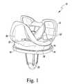
- FIG. 1is a perspective view of a knee prosthesis
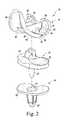
- FIG. 2is an exploded perspective view of the knee prosthesis of FIG. 1 ;
- FIG. 3is a perspective view of the femoral component of the knee prosthesis of FIG. 1 ;
- FIG. 4is a sagittal cross section view of the femoral component of FIG. 3 ;
- FIG. 5is an enlarged, fragmentary view of a portion of FIG. 4 showing the posterior condyles of the femoral component in greater detail;
- FIG. 6is a view similar to FIG. 4 , but showing another embodiment of the femoral component in which both the posterior and anterior cement pockets are angled;
- FIG. 7is a perspective view of a unicompartmental femoral component
- FIG. 8is a sagittal cross sectional view of the unicompartmental femoral component of FIG. 7 ;
- FIG. 9is a plan view of the inferior side of the tibial tray of the knee prosthesis of FIG. 1 ;
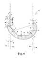
- FIG. 10is a sagittal cross section view of the tibial tray taken along the line 10 - 10 of FIG. 9 , as viewed in the direction of the arrows;
- FIG. 11is a sagittal cross section view of the tibial tray taken along the line 11 - 11 of FIG. 9 , as viewed in the direction of the arrows;
- FIG. 12is cross section view of an all-poly tibial component.
- Terms representing anatomical referencessuch as anterior, posterior, medial, lateral, superior, inferior, etcetera, may be used throughout this disclosure in reference to both the orthopaedic implants described herein and a patient's natural anatomy. Such terms have well-understood meanings in both the study of anatomy and the field of orthopaedics. Use of such anatomical reference terms in the specification and claims is intended to be consistent with their well-understood meanings unless noted otherwise.
- the knee prosthesis 10includes a femoral component 12 , a tibial tray 14 , and a bearing 16 .
- the femoral component 12is configured to be secured to a surgically-prepared end of a patient's distal femur (not shown), whereas the tibial tray 14 is configured to be secured to a surgically-prepared end of a patient's proximal tibia (not shown).
- the tibial tray 14includes a platform 18 having a fixation member, such as an elongated stem 20 , extending away from its lower surface.
- the bearing 16includes a stem 22 (see FIG. 2 ) that is positionable within a complementary bore 24 (see FIG. 2 ) in the tibial tray 14 . In such a way, the bearing 16 is free to rotate relative to the tibial tray 14 .
- the bearing 16may be snap-fit or otherwise secured to the tibial tray 14 . In such a way, the bearing 16 is fixed relative to the tibial tray 14 (i.e., it is not rotative or moveable in the anterior/posterior or medial/lateral directions).
- other fixation memberssuch as one or more short pegs or posts, may be used in lieu of the elongated stem 20 .
- the bearing 16includes a lateral articular surface 26 and a medial articular surface 28 .
- the articular surfaces 26 , 28are configured to articulate with a lateral condyle surface 30 and a medial condyle surface 32 , respectively, of the femoral component 12 .
- the femoral component 12is configured to emulate the configuration of the patient's natural femoral condyles, and, as such, the lateral condyle surface 30 and the medial condyle surface 32 are configured (e.g., curved) in a manner which mimics the condyles of the natural femur.
- the lateral condyle surface 30 and the medial condyle surface 32are spaced apart from one another thereby defining an intercondylar notch therebetween.
- the components of the knee prosthesis 10 that engage the natural bonemay be constructed with a biocompatible metal, such as a cobalt chrome alloy, although other materials, such as ceramics, may also be used.
- a biocompatible metalsuch as a cobalt chrome alloy
- the bone engaging surfaces of these componentsmay be textured to facilitate cementing the component to the bone. Such surfaces may also be porous coated to promote bone ingrowth for permanent fixation.
- the bearing 16may be constructed with a material that allows for smooth articulation between the bearing 16 and the femoral component 12 , such as a polymeric material.
- a polymeric materialis polyethylene such as ultrahigh molecular weight polyethylene (UHMWPE), although other biocompatible polymers may be used.
- UHMWPEultrahigh molecular weight polyethylene
- the femoral component 12is herein illustratively described as a monolithic component, it is characterized by a number of “regions” or “structures”.
- the anterior structure of the femoral component 12is referred to as an anterior flange 34 .
- the anterior flange 34transitions to an anterior chamfer region 36 , which, in turn, transitions to a distal condylar region 38 .
- the distal condylar region 38transitions to a posterior chamfer region 40 .
- a pair of posterior femoral condyles 42form the posterior structure of the femoral component 12 .
- both the lateral condyle surface 30 and the medial condyle surface 32are formed in the articular side 44 of the femoral component 12 .
- a fixation side 48is opposite the articular side 44 , and is the side of the femoral component 12 that contacts the surgically-prepared distal femur of the patient.
- the fixation side 48includes multiple surfaces that mate with planar surfaces surgically cut into the patient's distal femur.
- a pair of posterior fixation surfaces 50are opposite the posterior condyle surfaces 52 , with one of the posterior fixation surfaces 50 being the medial fixation surface, the other the lateral fixation surface.
- the posterior fixation surfaces 50extend generally in the superior/inferior direction.
- a pair of distal fixation surfaces 58are opposite the distal condyle surfaces 60 .
- the distal fixation surfaces 58extend generally in the anterior/posterior direction.
- the medial and lateral posterior-chamfer fixation surfaces 54are opposite the posterior-chamfer condyle surfaces 56 .
- the medial and lateral posterior-chamfer fixation surfaces 54extend superiorly and posteriorly from their respective medial and lateral distal fixation surfaces 58 in the direction toward their respective posterior fixation surfaces 50 .
- the medial and lateral anterior-chamfer fixation surfaces 62are opposite the anterior-chamfer condyle surfaces 64 , respectively, and extend superiorly and anteriorly away from their respective distal fixation surfaces 58 in the direction toward an anterior fixation surface 66 .
- the anterior fixation surface 66is opposite the anterior condyle surface 68 and, like the posterior fixation surfaces 50 , extends generally in the superior/inferior direction.
- Each of the fixation surfaceshas a cement pocket formed therein.
- a posterior cement pocket 70is formed in each of the posterior fixation surfaces 50
- a posterior-chamfer cement pocket 72is formed in each of the posterior-chamfer fixation surfaces 54
- a distal cement pocket 74is formed in each of the distal fixation surfaces 58
- an anterior-chamfer cement pocket 76is formed in each of the anterior-chamfer fixation surfaces 62
- an anterior cement pocket 78is formed in the anterior fixation surface 66 .
- the adjacent cement pocketsare contiguous with one another such that a single, continuous cement pocket is formed in the fixation side 48 of the femoral component.
- Each of the cement pockets 70 , 72 , 74 , 76 , 78is formed by a sidewall 80 that extends away from a mounting rim 82 .
- the sidewall 80forms the perimeter of the respective cement pockets 70 , 72 , 74 , 76 , 78 .
- a bottom wall 84is spaced apart from the mounting rim 82 and is connected thereto by the sidewall 80 . In such a way, the sidewall 80 and the bottom wall 84 collectively define the respective cement pockets 70 , 72 , 74 , 76 , 78 .
- each of the posterior-chamfer cement pocket 72 , the distal cement pocket 74 , the anterior-chamfer cement pocket 76 , and the anterior cement pocket 78is approximately equal.
- the posterior cement pocket 70is angled and, as a result, is deeper at its inferior end than on its superior end.
- the posterior cement pocket 70is formed by a sidewall 80 ′ that extends posteriorly from the mounting rim 82 ′ of the posterior fixation surface 50 to the bottom wall 84 ′.
- the inferior end 86 of the sidewall 80 ′is wider than the superior end 88 of the sidewall 80 ′.
- the posterior cement pocket 70is deeper at its inferior end 90 than at its superior end 92 .
- the superior end 92 of the posterior cement pocket 70is approximately equal to the depth of the other cement pockets 72 , 74 , 76 , and 78 .
- Such an arrangementcreates an angled bottom wall 84 ′.
- the bottom wall 84 ′slopes anteriorly from its inferior end 86 to its superior end 88 .
- This sloped arrangementis illustratively shown in the cross sectional view of FIG. 5 .
- an imaginary plane 96is defined by the mounting rim 82 ′ of the posterior fixation surface 50
- the bottom wall 84 ′ of the posterior fixation surface 50defines an imaginary plane 94 .
- the two imaginary planes 94 , 96form an acute angle ( ⁇ ) therebetween. Such an acute angle is indicative of the slope of the bottom wall 84 ′ relative to the mounting rim 82 ′.
- the cement pockets 70 , 72 , 74 , 76 , 78are preloaded with bone cement.
- the femoral component 12is then positioned on the patient's surgically-prepared distal femur, which has also been coated in bone cement.
- the angled arrangement of posterior cement pocket 70hydraulically loads the bone cement within the cement pocket. This enhances containment of the bone cement and reduces the occurrences of cement plowing.
- the arrangement of the posterior cement pocket 70also improves filling of the bone cement and pressurization which, in turn, leads to enhanced bonding of the femoral component 12 to the distal femur.
- both the posterior cement pocket 70 and the anterior cement pocket 78are angled. As such, both cement pockets 70 , 78 are deeper at their respective inferior ends than at their respective superior ends.
- the posterior cement pocket 70is essentially the same as discussed above in regard to FIGS. 1-5 .
- the anterior cement pocket 78it is formed by a sidewall 80 ′′ that extends anteriorly from the mounting rim 82 ′′ of the anterior fixation surface 66 to the bottom wall 84 ′′.
- the inferior end 106 of the sidewall 80 ′′is wider than the superior end 108 of the sidewall 80 ′′.
- the anterior cement pocket 78is deeper at its inferior end 110 than at its superior end 112 .
- the superior end 112 of the anterior cement pocket 78is approximately equal to the depth of the other cement pockets 72 , 74 , and 76 .
- Such an arrangementcreates an angled bottom wall 84 ′′.
- the bottom wall 84 ′′ of the anterior cement pocket 78slopes posteriorly from its inferior end 106 to its superior end 108 .
- This sloped arrangementis illustratively shown in FIG. 6 in which an imaginary plane 114 is defined by the mounting rim 82 ′′ of the anterior fixation surface 66 , whereas the bottom wall 84 ′′ of the anterior fixation surface 66 defines an imaginary plane 116 .
- the two imaginary planes 114 , 116form an acute angle ( ⁇ ) therebetween. Such an acute angle is indicative of the slope of the bottom wall 84 ′′ relative to the mounting rim 82 ′′.
- the cement pockets 70 , 72 , 74 , 76 , 78are preloaded with bone cement.
- the femoral component 12is then positioned on the patient's surgically-prepared distal femur, which has also been coated in bone cement.
- the angled arrangement of the cement pockets 70 , 78hydraulically loads the bone cement within the cement pockets 70 , 78 . This enhances containment of the bone cement and reduces the occurrences of cement plowing. This also improves filling of the bone cement and pressurization which, in turn, leads to enhanced bonding of the femoral component 12 to the distal femur.
- FIG. 6illustratively shows both the posterior cement pocket 70 and the anterior cement pocket 78 being angled, it should be appreciated that other embodiments are also contemplated.
- the femoral component 12may be embodied with only the posterior cement pocket 70 being angled.
- the femoral component 12may be embodied with only the anterior cement pocket 78 being angled.
- the femoral component 12may also be embodied as a unicompartmental femoral component.
- the posterior cement pocket 70 of the unicompartmental femoral component 12may be angled.
- the angled arrangement of posterior cement pocket 70hydraulically loads the bone cement within the cement pocket. This enhances containment of the bone cement and reduces the occurrences of cement plowing.
- the arrangement of the posterior cement pocket 70also improves filling of the bone cement and pressurization which, in turn, leads to enhanced bonding of the unicompartmental femoral component 12 to the distal femur.
- a flat planar surface 118is formed in the superior side 120 of the tibial tray 14 .
- the superior surface 118 of the tibial tray's platform 18defines a smooth planar surface on which the bearing 16 of the knee prosthesis 10 is free to rotate when the bearing's stem 22 (see FIG. 2 ) is positioned within the complementary bore 24 (see FIG. 2 ) of the tibial tray 14 .
- the superior surface 118 of the tibial tray's platform 18may be embodied with one or more features on which the bearing 16 may be snap-fit or otherwise secured to the tibial tray 14 .
- the bearing 16is fixed relative to the tibial tray 14 (i.e., it is not rotative or moveable in the anterior/posterior or medial/lateral directions).
- the tibial tray's inferior side 122is opposite its superior side 120 , and is the side of the tibial tray 14 that contacts the surgically-prepared proximal tibia of the patient.
- the elongated stem 20extends inferiorly away from the tibial tray's inferior side 122 .
- the tibial tray's inferior side 122includes multiple surfaces that mate with planar surfaces surgically cut into the patient's proximal tibia. Specifically, as shown in FIGS. 9 and 10 , an inferior fixation surface 124 extends generally in the transverse plane (i.e., in the direction of the anatomical transverse plane).
- the inferior fixation surface 124has a cement pocket 126 formed therein.
- the tibial tray's fins 128divide the cement pocket 126 into separate cement pockets at various locations along the tray's medial/lateral width.
- an anterior cement pocket 130is positioned anteriorly of the tray's fins 128 with a posterior cement pocket 132 being positioned posteriorly of the tray's fins 128 .
- the cement pockets 130 , 132are contiguous with one another such that a single, continuous cement pocket 126 is formed in the inferior side 122 of the tibial tray 14 . It should be appreciated; however, that the tibial tray 14 could be embodied with one or more separate cement pockets.
- Each of the cement pockets 126 , 130 , 132is formed by a sidewall 140 that extends superiorly away from a mounting rim 142 .
- the sidewall 140forms the perimeter of the respective cement pockets 126 , 130 , 132 .
- a top wall 144is spaced apart from the mounting rim 142 and is connected thereto by the sidewall 140 . In such a way, the sidewall 140 and the top wall 144 collectively define the respective cement pockets 126 , 130 , 132 .
- the cement pocket 126is angled and, as a result, deeper at its anterior end than on its posterior end.
- the anterior end 146 of the sidewall 140is wider than the posterior end 148 of the sidewall 140 .
- the cement pocket 126is deeper at its anterior end 150 than at its posterior end 152 .
- the individual cement pockets formed by the fins 128i.e., the anterior cement pocket 130 and the posterior cement pocket 132
- each of the cement pockets 130 , 132has a similar arrangement in which their respective anterior ends are deeper than their respective posterior ends.
- the anterior end 154 of the anterior cement pocket 130is deeper than its posterior end 156 .
- the anterior end 158 of the posterior cement pocket 132is deeper than its posterior end 160 .
- Such an arrangementcreates an angled top wall 144 .
- the top wall 144slopes inferiorly from its anterior end 166 to its posterior end 168 .
- This sloped arrangementis illustratively shown in the cross sectional views of FIGS. 10 and 11 .
- an imaginary plane 170is defined by the mounting rim 142 of the inferior fixation surface 124
- the top wall 144 of the inferior fixation surface 124defines an imaginary plane 172 .
- the two imaginary planes 170 , 172form an acute angle ( ⁇ ) therebetween. Such an acute angle is indicative of the slope of the top wall 144 relative to the mounting rim 142 .
- the cement pocket 126is preloaded with bone cement.
- the tibial tray 14is then positioned on the patient's surgically-prepared proximal tibia, which has also been coated in bone cement.
- the angled arrangement of cement pocket 126hydraulically loads the bone cement within the cement pocket. This enhances containment of the bone cement and reduces the occurrences of cement plowing.
- the arrangement of the cement pocket 126also forces any excess bone cement out the anterior side of the tibial tray 14 where it can be readily wiped away or otherwise removed by the surgeon.
- the tibial componentmay also be embodied as an all-poly tibial component. That is, in lieu of a modular design in which the tibial tray and the bearing are embodied as separate components, the concepts of the present disclosure may be utilized in the design of a monolithic polymeric tibial component.
- the lateral articular surface 26 and the medial articular surface 28configured to articulate with a lateral condyle surface 30 and a medial condyle surface 32 of the femoral component 12 , respectively, are formed in the superior side 120 of the tibial component.
- the cement pocket 126 of the all-poly tibial component of FIG. 12may be angled.
- the angled arrangement of cement pocket 126hydraulically loads the bone cement within the cement pocket and forces any excess bone cement out the anterior side of the all-poly tibial component where it can be readily wiped away or otherwise removed by the surgeon.
Landscapes
- Health & Medical Sciences (AREA)
- Orthopedic Medicine & Surgery (AREA)
- Physical Education & Sports Medicine (AREA)
- Cardiology (AREA)
- Oral & Maxillofacial Surgery (AREA)
- Transplantation (AREA)
- Engineering & Computer Science (AREA)
- Biomedical Technology (AREA)
- Heart & Thoracic Surgery (AREA)
- Vascular Medicine (AREA)
- Life Sciences & Earth Sciences (AREA)
- Animal Behavior & Ethology (AREA)
- General Health & Medical Sciences (AREA)
- Public Health (AREA)
- Veterinary Medicine (AREA)
- Prostheses (AREA)
Abstract
Description
Claims (19)
Priority Applications (11)
| Application Number | Priority Date | Filing Date | Title |
|---|---|---|---|
| US13/249,496US8317870B2 (en) | 2010-09-30 | 2011-09-30 | Tibial component of a knee prosthesis having an angled cement pocket |
| AU2012227339AAU2012227339B2 (en) | 2011-09-30 | 2012-09-26 | Tibial component of a knee prosthesis having an angled cement pocket |
| ES14185322.6TES2672204T3 (en) | 2011-09-30 | 2012-09-28 | Tibial component of a knee prosthesis with an angled cement pocket |
| JP2012216123AJP5989490B2 (en) | 2011-09-30 | 2012-09-28 | Tibial component of knee prosthesis with angled cement pocket |
| ZA2012/07301AZA201207301B (en) | 2011-09-30 | 2012-09-28 | Tibial component of a knee prosthesis having an angled cement pocket |
| EP14185322.6AEP2842520B1 (en) | 2011-09-30 | 2012-09-28 | Tibial component of a knee prosthesis having an angled cement pocket |
| ES12186701.4TES2562161T3 (en) | 2011-09-30 | 2012-09-28 | Tibial component of a knee prosthesis that has an inclined cement pocket |
| EP12186701.4AEP2574312B1 (en) | 2011-09-30 | 2012-09-28 | Tibial component of a knee prosthesis having an angled cement pocket |
| CN201210371283.1ACN103027767B (en) | 2011-09-30 | 2012-09-28 | There is the tibial component of the knee-joint prosthesis in angled bone cement chamber |
| US13/672,229US8845746B2 (en) | 2010-09-30 | 2012-11-08 | Femoral component of a knee prosthesis having an angled posterior cement pocket |
| US14/482,227US9724202B2 (en) | 2010-09-30 | 2014-09-10 | Femoral component of a knee prosthesis having an angled cement pocket |
Applications Claiming Priority (2)
| Application Number | Priority Date | Filing Date | Title |
|---|---|---|---|
| US12/894,651US8287601B2 (en) | 2010-09-30 | 2010-09-30 | Femoral component of a knee prosthesis having an angled cement pocket |
| US13/249,496US8317870B2 (en) | 2010-09-30 | 2011-09-30 | Tibial component of a knee prosthesis having an angled cement pocket |
Related Parent Applications (1)
| Application Number | Title | Priority Date | Filing Date |
|---|---|---|---|
| US12/894,651Continuation-In-PartUS8287601B2 (en) | 2010-09-30 | 2010-09-30 | Femoral component of a knee prosthesis having an angled cement pocket |
Related Child Applications (1)
| Application Number | Title | Priority Date | Filing Date |
|---|---|---|---|
| US13/672,229ContinuationUS8845746B2 (en) | 2010-09-30 | 2012-11-08 | Femoral component of a knee prosthesis having an angled posterior cement pocket |
Publications (2)
| Publication Number | Publication Date |
|---|---|
| US20120109325A1 US20120109325A1 (en) | 2012-05-03 |
| US8317870B2true US8317870B2 (en) | 2012-11-27 |
Family
ID=45997535
Family Applications (3)
| Application Number | Title | Priority Date | Filing Date |
|---|---|---|---|
| US13/249,496Expired - Fee RelatedUS8317870B2 (en) | 2010-09-30 | 2011-09-30 | Tibial component of a knee prosthesis having an angled cement pocket |
| US13/672,229ActiveUS8845746B2 (en) | 2010-09-30 | 2012-11-08 | Femoral component of a knee prosthesis having an angled posterior cement pocket |
| US14/482,227Active2030-11-19US9724202B2 (en) | 2010-09-30 | 2014-09-10 | Femoral component of a knee prosthesis having an angled cement pocket |
Family Applications After (2)
| Application Number | Title | Priority Date | Filing Date |
|---|---|---|---|
| US13/672,229ActiveUS8845746B2 (en) | 2010-09-30 | 2012-11-08 | Femoral component of a knee prosthesis having an angled posterior cement pocket |
| US14/482,227Active2030-11-19US9724202B2 (en) | 2010-09-30 | 2014-09-10 | Femoral component of a knee prosthesis having an angled cement pocket |
Country Status (1)
| Country | Link |
|---|---|
| US (3) | US8317870B2 (en) |
Cited By (32)
| Publication number | Priority date | Publication date | Assignee | Title |
|---|---|---|---|---|
| US20100249533A1 (en)* | 2009-03-26 | 2010-09-30 | Jay Pierce | System and method for an orthopedic data repository and registry |
| US20120035736A1 (en)* | 2001-12-14 | 2012-02-09 | Btg International Limited | Tibial component |
| US20120265317A1 (en)* | 2011-04-15 | 2012-10-18 | Biomet Manufacturing Corp. | Pivoting tibial tray |
| US20130018477A1 (en)* | 2011-07-13 | 2013-01-17 | The General Hospital Corporation D/B/A Massachusetts General Hospital | Methods and Devices for Knee Joint Replacement with Anterior Cruciate Ligament Substitution |
| US8632604B2 (en)* | 2009-10-22 | 2014-01-21 | Depuy International Limited | Medical implant device |
| US20150250472A1 (en)* | 2014-03-07 | 2015-09-10 | Arthrosurface Incorporated | Delivery System for Articular Surface Implant |
| US9610168B2 (en) | 2014-05-12 | 2017-04-04 | Integra Lifesciences Corporation | Total ankle replacement prosthesis |
| US9820857B2 (en) | 2013-03-15 | 2017-11-21 | Depuy Ireland Unlimited Company | Surgical instrument and method of use |
| US10478200B2 (en) | 2009-04-17 | 2019-11-19 | Arthrosurface Incorporated | Glenoid resurfacing system and method |
| US10624748B2 (en) | 2014-03-07 | 2020-04-21 | Arthrosurface Incorporated | System and method for repairing articular surfaces |
| US10624749B2 (en) | 2003-02-24 | 2020-04-21 | Arthrosurface Incorporated | Trochlear resurfacing system and method |
| US10624752B2 (en) | 2006-07-17 | 2020-04-21 | Arthrosurface Incorporated | Tibial resurfacing system and method |
| US10695096B2 (en) | 2013-04-16 | 2020-06-30 | Arthrosurface Incorporated | Suture system and method |
| US10828168B2 (en) | 2017-05-10 | 2020-11-10 | Howmedica Osteonics Corp. | Patient specific composite knee replacement |
| US10945743B2 (en) | 2009-04-17 | 2021-03-16 | Arthrosurface Incorporated | Glenoid repair system and methods of use thereof |
| US10959740B2 (en) | 2006-12-11 | 2021-03-30 | Arthrosurface Incorporated | Retrograde resection apparatus and method |
| US11160663B2 (en) | 2017-08-04 | 2021-11-02 | Arthrosurface Incorporated | Multicomponent articular surface implant |
| US11160659B2 (en) | 2015-09-21 | 2021-11-02 | Zimmer, Inc. | Prosthesis system including tibial bearing component |
| US11191552B2 (en) | 2012-07-03 | 2021-12-07 | Arthrosurface, Incorporated | System and method for joint resurfacing and repair |
| US11224519B2 (en) | 2010-07-24 | 2022-01-18 | Zimmer, Inc. | Asymmetric tibial components for a knee prosthesis |
| US11324599B2 (en) | 2017-05-12 | 2022-05-10 | Zimmer, Inc. | Femoral prostheses with upsizing and downsizing capabilities |
| US11324598B2 (en) | 2013-08-30 | 2022-05-10 | Zimmer, Inc. | Method for optimizing implant designs |
| US11426282B2 (en)* | 2017-11-16 | 2022-08-30 | Zimmer, Inc. | Implants for adding joint inclination to a knee arthroplasty |
| US11471288B2 (en) | 2010-09-10 | 2022-10-18 | Zimmer, Inc. | Motion facilitating tibial components for a knee prosthesis |
| US11478358B2 (en) | 2019-03-12 | 2022-10-25 | Arthrosurface Incorporated | Humeral and glenoid articular surface implant systems and methods |
| US11547571B2 (en) | 2017-03-10 | 2023-01-10 | Zimmer, Inc. | Tibial prosthesis with tibial bearing component securing feature |
| US11607319B2 (en) | 2014-03-07 | 2023-03-21 | Arthrosurface Incorporated | System and method for repairing articular surfaces |
| US11712276B2 (en) | 2011-12-22 | 2023-08-01 | Arthrosurface Incorporated | System and method for bone fixation |
| US11911279B2 (en) | 2018-04-30 | 2024-02-27 | Zimmer, Inc. | Posterior stabilized prosthesis system |
| US12324749B2 (en) | 2022-07-25 | 2025-06-10 | DePuy Synthes Products, Inc. | Impaction handle for implanting a tibial tray of an orthopaedic knee prosthesis and associated method of making the same |
| US12357470B2 (en) | 2022-12-16 | 2025-07-15 | Depuy Ireland Unlimited Company | Impaction instrument for implanting an orthopaedic knee prosthesis and associated method of using the same |
| US12383407B2 (en) | 2011-11-18 | 2025-08-12 | Zimmer, Inc. | Tibial bearing component for a knee prosthesis with improved articular characteristics |
Families Citing this family (9)
| Publication number | Priority date | Publication date | Assignee | Title |
|---|---|---|---|---|
| US8900316B2 (en) | 2010-01-29 | 2014-12-02 | Smith & Nephew, Inc. | Cruciate-retaining knee prosthesis |
| USD748786S1 (en)* | 2013-10-16 | 2016-02-02 | Depuy (Ireland) | Tibial trial component |
| GB201400287D0 (en)* | 2014-01-08 | 2014-02-26 | Depuy Ireland | Femoral component of a knee joint prosthesis |
| CN104840273A (en)* | 2015-05-21 | 2015-08-19 | 北京爱康宜诚医疗器材股份有限公司 | Prosthesis component and method for manufacturing same |
| EP4268772A3 (en)* | 2017-10-26 | 2023-12-13 | Smith & Nephew, Inc. | Orthopedic implants |
| IT201900012201A1 (en)* | 2019-07-17 | 2021-01-17 | Tecres Spa | DEVICE WITH ENCLOSURE AND PROSTHETIC COMPONENT EQUIPPED WITH THIS DEVICE |
| AU2020385363A1 (en)* | 2019-11-12 | 2022-06-30 | Depuy Ireland Unlimited Company | Composite orthopaedic prosthesis and method of making the same |
| RU196434U1 (en)* | 2019-12-27 | 2020-02-28 | Общество с ограниченной ответственностью "ОСТЕОМЕД-М" | TIBIAL KNEE JOINT ENDOPROTHESIS COMPONENT |
| WO2025171266A1 (en)* | 2024-02-09 | 2025-08-14 | Ignite Orthomotion, Llc | Implants, systems and methods of using the same |
Citations (151)
| Publication number | Priority date | Publication date | Assignee | Title |
|---|---|---|---|---|
| US3965490A (en)* | 1974-11-14 | 1976-06-29 | Howmedica, Inc. | Femoral insert for hip joint prosthesis |
| US4530116A (en) | 1982-10-15 | 1985-07-23 | Sulzer Brothers Limited | Anchoring shank for a bone implant |
| US4808185A (en) | 1986-02-07 | 1989-02-28 | Penenberg Brad L | Tibial prosthesis, template and reamer |
| US4938769A (en) | 1989-05-31 | 1990-07-03 | Shaw James A | Modular tibial prosthesis |
| US4944760A (en) | 1983-10-26 | 1990-07-31 | Pfizer Hospital Products Group, Inc. | Method and instrumentation for the replacement of a knee prosthesis |
| US4963152A (en) | 1986-10-27 | 1990-10-16 | Intermedics Orthopedics, Inc. | Asymmetric prosthetic tibial component |
| US5037423A (en) | 1983-10-26 | 1991-08-06 | Pfizer Hospital Products Group, Inc. | Method and instrumentation for the replacement of a knee prosthesis |
| US5108442A (en) | 1991-05-09 | 1992-04-28 | Boehringer Mannheim Corporation | Prosthetic implant locking assembly |
| US5171276A (en) | 1990-01-08 | 1992-12-15 | Caspari Richard B | Knee joint prosthesis |
| US5201768A (en) | 1990-01-08 | 1993-04-13 | Caspari Richard B | Prosthesis for implant on the tibial plateau of the knee |
| US5207711A (en) | 1990-01-08 | 1993-05-04 | Caspari Richard B | Knee joint prosthesis |
| US5326361A (en) | 1991-09-16 | 1994-07-05 | Research And Education Institute, Inc. | Total knee endoprosthesis with fixed flexion-extension axis of rotation |
| US5330534A (en) | 1992-02-10 | 1994-07-19 | Biomet, Inc. | Knee joint prosthesis with interchangeable components |
| US5344460A (en) | 1992-10-30 | 1994-09-06 | Encore Orthopedics, Inc. | Prosthesis system |
| US5344461A (en) | 1993-02-12 | 1994-09-06 | Zimmer, Inc. | Modular implant provisional |
| US5458637A (en) | 1994-11-21 | 1995-10-17 | Zimmer, Inc. | Orthopaedic base component with modular augmentation block |
| US5509934A (en)* | 1992-02-28 | 1996-04-23 | Osteonics Corp. | Prosthetic knee tibial component constructed of synthetic polymeric material |
| US5658344A (en) | 1995-12-29 | 1997-08-19 | Johnson & Johnson Professional, Inc. | Tibial insert reinforcement pin |
| US5683472A (en) | 1995-12-29 | 1997-11-04 | Johnson & Johnson Professional, Inc. | Femoral stem attachment for a modular knee prosthesis |
| US5690636A (en) | 1995-12-21 | 1997-11-25 | Johnson & Johnson Professional, Inc. | Punch system for tibial prosthesis |
| US5702463A (en) | 1996-02-20 | 1997-12-30 | Smith & Nephew Inc. | Tibial prosthesis with polymeric liner and liner insertion/removal instrument |
| US5702447A (en) | 1995-11-30 | 1997-12-30 | Tornier S.A. | Device for the attachment of a glenoid prosthesis of the shoulder blade |
| US5702464A (en) | 1996-02-20 | 1997-12-30 | Smith & Nephew Inc. | Modular trial tibial insert |
| JPH10137271A (en) | 1996-05-28 | 1998-05-26 | Howmedica Internatl Inc | Tibia element for artifitial knee for exchange |
| US5755803A (en) | 1994-09-02 | 1998-05-26 | Hudson Surgical Design | Prosthetic implant |
| US5755808A (en) | 1996-06-27 | 1998-05-26 | Joint Medical Products, Corporation | Connector plug for multi-component orthopedic implant |
| US5766257A (en) | 1997-01-28 | 1998-06-16 | Implant Manufacturing And Testing Corporation | Artificial joint having natural load transfer |
| US5800546A (en) | 1995-08-14 | 1998-09-01 | Smith & Nephew, Inc. | Impactor apparatus for assembling modular orthopedic prosthesis components |
| US5879387A (en) | 1994-08-25 | 1999-03-09 | Howmedica International Inc. | Prosthetic bearing element and method of manufacture |
| US5906644A (en) | 1996-08-30 | 1999-05-25 | Powell; Douglas Hunter | Adjustable modular orthopedic implant |
| US5951564A (en) | 1996-12-18 | 1999-09-14 | Bristol-Myers Squibb Company | Orthopaedic positioning apparatus |
| US5951603A (en)* | 1997-09-25 | 1999-09-14 | Johnson & Johnson Professional, Inc. | Rotatable joint prosthesis with axial securement |
| US5976147A (en) | 1997-07-11 | 1999-11-02 | Johnson & Johnson Professional, Inc | Modular instrumentation for bone preparation and implant trial reduction of orthopedic implants |
| US6010534A (en) | 1997-09-25 | 2000-01-04 | Johnson & Johnson Professional, Inc. | Rotatable tibial prosthesis with keyed axial securement |
| US6053945A (en) | 1997-09-25 | 2000-04-25 | Johnson & Johnson Professional, Inc. | Joint prosthesis having controlled rotation |
| WO2000051528A1 (en) | 1999-03-01 | 2000-09-08 | Biomet, Inc. | Method and apparatus for enabling access to an intramedullary canal of a femur through a femoral knee joint prosthesis |
| US6123728A (en) | 1997-09-17 | 2000-09-26 | Smith & Nephew, Inc. | Mobile bearing knee prosthesis |
| US6126692A (en) | 1998-06-25 | 2000-10-03 | New York Society For The Relief Of The Ruptured And Crippled Maintaining The Hospital For Special Surgery | Retaining mechanism for a modular tibial component of a knee prosthesis |
| US6139581A (en) | 1997-06-06 | 2000-10-31 | Depuy Orthopaedics, Inc. | Posterior compensation tibial tray |
| US6179876B1 (en) | 1998-11-04 | 2001-01-30 | Blake A. Stamper | Orthopedic prosthesis with cement compression ring and method |
| US6224632B1 (en)* | 1994-10-27 | 2001-05-01 | Biomedical Engineering Trust I | Prosthesis fixturing device |
| US6344059B1 (en) | 1996-02-26 | 2002-02-05 | Gabor Krakovits | Knee surface replacement prosthesis |
| EP1186277A2 (en) | 1996-05-28 | 2002-03-13 | Howmedica International Inc. | Tibial element for a replacement knee prosthesis |
| US6428577B1 (en) | 1998-05-20 | 2002-08-06 | Smith & Nephew, Inc. | Mobile bearing knee prosthesis |
| US6485519B2 (en) | 2001-01-29 | 2002-11-26 | Bristol-Myers Squibb Company | Constrained prosthetic knee with rotating bearing |
| US6494914B2 (en) | 2000-12-05 | 2002-12-17 | Biomet, Inc. | Unicondylar femoral prosthesis and instruments |
| US6503280B2 (en) | 2000-12-26 | 2003-01-07 | John A. Repicci | Prosthetic knee and method of inserting |
| US20030014122A1 (en) | 2001-04-02 | 2003-01-16 | Whiteside Biomechanics, Inc. | Tray and liner for joint replacement system |
| US6620198B2 (en) | 1999-10-07 | 2003-09-16 | Exactech, Inc. | Composite bearing inserts for total knee joints |
| US6645251B2 (en) | 2001-01-22 | 2003-11-11 | Smith & Nephew, Inc. | Surfaces and processes for wear reducing in orthopaedic implants |
| US6652592B1 (en) | 1997-10-27 | 2003-11-25 | Regeneration Technologies, Inc. | Segmentally demineralized bone implant |
| US20030220697A1 (en) | 2002-05-24 | 2003-11-27 | Justin Daniel F. | Modular femoral components for knee arthroplasty |
| US20030225456A1 (en) | 2000-05-01 | 2003-12-04 | Ek Steven W. | System and method for joint resurface repair |
| WO2003099106A2 (en) | 2002-05-24 | 2003-12-04 | Medicinelodge, Inc. | Modular femoral components for knee arthroplasty |
| US6660039B1 (en) | 1998-05-20 | 2003-12-09 | Smith & Nephew, Inc. | Mobile bearing knee prosthesis |
| US6679917B2 (en) | 2000-05-01 | 2004-01-20 | Arthrosurface, Incorporated | System and method for joint resurface repair |
| US20040019384A1 (en) | 2002-07-24 | 2004-01-29 | Bryan Kirking | Implantable prosthesis for measuring six force components |
| US20040039450A1 (en) | 2002-08-26 | 2004-02-26 | Griner Adam M. | Easily assembled provisional orthopaedic implant |
| US6716249B2 (en) | 2001-01-16 | 2004-04-06 | Edward R. Hyde | Joint prosthesis and method of implantation |
| US6719800B2 (en) | 2001-01-29 | 2004-04-13 | Zimmer Technology, Inc. | Constrained prosthetic knee with rotating bearing |
| US6773461B2 (en) | 2001-01-29 | 2004-08-10 | Zimmer Technology, Inc. | Constrained prosthetic knee with rotating bearing |
| US20050015153A1 (en) | 2002-05-24 | 2005-01-20 | Medicine Lodge, Inc. | Implants and related methods and apparatus for securing an implant on an articulating surface of an orthopedic joint |
| US6869448B2 (en) | 2002-01-18 | 2005-03-22 | Finsbury (Development) Limited | Prosthesis |
| US6875235B2 (en) | 1999-10-08 | 2005-04-05 | Bret A. Ferree | Prosthetic joints with contained compressible resilient members |
| US20050125068A1 (en) | 2003-12-05 | 2005-06-09 | Howmedica Osteonics Corp. | Orthopedic implant with angled pegs |
| US6923832B1 (en) | 2002-03-21 | 2005-08-02 | Trigon Incorporated | Revision tibial component |
| US6942670B2 (en) | 2000-12-27 | 2005-09-13 | Depuy Orthopaedics, Inc. | Prosthesis evaluation assembly and associated method |
| US6953479B2 (en) | 2001-07-16 | 2005-10-11 | Smith & Nephew, Inc. | Orthopedic implant extension |
| US6994730B2 (en) | 2003-01-31 | 2006-02-07 | Howmedica Osteonics Corp. | Meniscal and tibial implants |
| US20060030945A1 (en) | 2004-08-05 | 2006-02-09 | Wright Abraham P | Modular orthopaedic implant system with multi-use stems |
| US20060047283A1 (en) | 2004-08-25 | 2006-03-02 | Evans Boyd M Iii | In-vivo orthopedic implant diagnostic device for sensing load, wear, and infection |
| US7025788B2 (en) | 2001-02-23 | 2006-04-11 | Biomet, Inc. | Knee joint prosthesis |
| US20060100714A1 (en) | 2003-04-02 | 2006-05-11 | Ortho Development Corporation | Tibial augment connector |
| US7048741B2 (en) | 2002-05-10 | 2006-05-23 | Swanson Todd V | Method and apparatus for minimally invasive knee arthroplasty |
| US20060111790A1 (en) | 2004-11-24 | 2006-05-25 | Dietz Terry L | Adjustable knee tibial trial insert |
| US7070622B1 (en) | 2002-07-03 | 2006-07-04 | Biomet, Inc. | Prosthesis having a modular soft tissue fixation mechanism |
| US7077867B1 (en) | 1994-08-12 | 2006-07-18 | Diamicron, Inc. | Prosthetic knee joint having at least one diamond articulation surface |
| US7087082B2 (en) | 1998-08-03 | 2006-08-08 | Synthes (Usa) | Bone implants with central chambers |
| US7108720B2 (en) | 2003-03-31 | 2006-09-19 | Depuy Products, Inc. | Reduced wear orthopaedic implant apparatus and method |
| US20070061014A1 (en) | 2005-09-14 | 2007-03-15 | Hjs Gelenk System Gmbh | Apparatus and method for determining and adjusting the optimal relative position of a functional surface and of correspondingly shaped implant components of an artificial joint |
| US7208013B1 (en) | 1990-06-28 | 2007-04-24 | Bonutti Ip, Llc | Composite surgical devices |
| US20070100463A1 (en) | 2005-10-31 | 2007-05-03 | Aram Luke J | Modular fixed and mobile bearing prosthesis system |
| US20070162143A1 (en) | 2002-10-23 | 2007-07-12 | Wasielewski Ray C | Biologic modular tibial and femoral component augments for use with total knee arthroplasty |
| US7255715B2 (en) | 2002-08-30 | 2007-08-14 | Biomet Manufacturing Corp. | Integrated prosthetic assembly |
| US20070219639A1 (en) | 2006-03-14 | 2007-09-20 | Mako Surgical Corporation | Prosthetic device and system and method for implanting prosthetic device |
| US7278997B1 (en) | 2003-03-07 | 2007-10-09 | Theken Spine, Llc | Instrument guide and implant holder |
| US7297164B2 (en) | 2002-11-22 | 2007-11-20 | Zimmer Technology, Inc. | Modular knee prosthesis |
| US20080004708A1 (en) | 2006-06-30 | 2008-01-03 | Wyss Joseph G | Hinged orthopaedic prosthesis |
| US20080021567A1 (en) | 2006-07-18 | 2008-01-24 | Zimmer Technology, Inc. | Modular orthopaedic component case |
| US7341602B2 (en) | 1999-05-10 | 2008-03-11 | Fell Barry M | Proportioned surgically implantable knee prosthesis |
| US7357817B2 (en) | 2005-05-19 | 2008-04-15 | Howmedica Osteonics Corp. | Modular keel tibial component |
| US20080097615A1 (en) | 2006-09-25 | 2008-04-24 | The Hospital For Special Surgery | Posterior stabilized knee prosthesis |
| WO2008048820A2 (en) | 2006-10-13 | 2008-04-24 | Depuy Products, Inc. | Mobile/fixed prosthetic knee systems |
| US20080114464A1 (en) | 2006-10-13 | 2008-05-15 | Barnett Gary D | Mobile/fixed prosthetic knee systems |
| US20080114462A1 (en) | 2006-11-09 | 2008-05-15 | Hayes Medical, Inc. | System and method for joint arthroplasty |
| US20080119940A1 (en) | 2002-12-20 | 2008-05-22 | Otto Jason K | High performance knee prostheses |
| US20080133019A1 (en) | 2006-11-30 | 2008-06-05 | Bloorview Kids Rehab | Artificial joint with locking mechansim |
| US20080195108A1 (en) | 2007-02-12 | 2008-08-14 | Jmea Corporation | Total Knee Arthoplasty System |
| US20090048680A1 (en) | 2007-08-07 | 2009-02-19 | Aequos Endoprothetik Gmbh | Artificial joint and a joint part intended for this purpose |
| US7494507B2 (en) | 2000-01-30 | 2009-02-24 | Diamicron, Inc. | Articulating diamond-surfaced spinal implants |
| US7497874B1 (en) | 2001-02-23 | 2009-03-03 | Biomet Manufacturing Corp. | Knee joint prosthesis |
| US20090082873A1 (en)* | 2007-09-25 | 2009-03-26 | Hazebrouck Stephen A | Fixed-bearing knee prosthesis |
| US20090088859A1 (en) | 2007-09-28 | 2009-04-02 | Hazebrouck Stephen A | Fixed-bearing knee prosthesis having interchangeable components |
| US20090125114A1 (en) | 2007-10-10 | 2009-05-14 | Biomet Manufacturing Corp. | Knee joint prosthesis system and method for implantation |
| US20090125115A1 (en) | 2007-05-16 | 2009-05-14 | Zimmer, Inc. | Knee system and method of making same |
| US7563286B2 (en) | 2002-08-15 | 2009-07-21 | Synthes Usa, Llc | Controlled artificial intervertebral disc implant |
| US7572295B2 (en) | 2001-12-04 | 2009-08-11 | Active Implants Corporation | Cushion bearing implants for load bearing applications |
| US7578850B2 (en) | 2005-04-18 | 2009-08-25 | Uni-Knee, Llc | Unicondylar knee implant |
| US20090265012A1 (en) | 2001-06-14 | 2009-10-22 | Alexandria Research Technologies, Inc. | Implants for partial knee arthroplasty |
| US20090265013A1 (en) | 2008-04-17 | 2009-10-22 | Mandell Steven L | Tibial component of an artificial knee joint |
| US20090264894A1 (en) | 2008-04-21 | 2009-10-22 | Ray Wasielewski | Method of designing orthopedic implants using in vivo data |
| US7608079B1 (en) | 2004-03-05 | 2009-10-27 | Biomet Manufacturing Corp. | Unicondylar knee apparatus and system |
| US7611519B2 (en) | 2001-11-05 | 2009-11-03 | Depuy (Ireland) Limited | Methods for selecting knee prosthesis elements and device therefor |
| US7618462B2 (en) | 2000-05-01 | 2009-11-17 | Arthrosurface Incorporated | System and method for joint resurface repair |
| US20090295035A1 (en) | 2003-11-14 | 2009-12-03 | Cherry Creek Orthopedic Specialists | Total knee joint mold and methods |
| US7628817B1 (en) | 2006-12-14 | 2009-12-08 | Howmedica Osteonics Corp. | Soft tissue deflection at a prosthetic joint |
| US7635390B1 (en) | 2000-01-14 | 2009-12-22 | Marctec, Llc | Joint replacement component having a modular articulating surface |
| US20090326666A1 (en) | 2008-06-30 | 2009-12-31 | Wyss Joseph G | Posterior stabilized orthopaedic prosthesis |
| US20090326664A1 (en) | 2008-06-30 | 2009-12-31 | Wagner Christel M | Posterior cructiate-retaining orthopaedic knee prosthesis having controlled condylar curvature |
| US20090326665A1 (en) | 2008-06-30 | 2009-12-31 | Wyss Joseph G | Posterior stabilized orthopaedic knee prosthesis having controlled condylar curvature |
| US20090326667A1 (en) | 2008-06-30 | 2009-12-31 | Williams John L | Orthopaedic femoral component having controlled condylar curvature |
| US20090326663A1 (en) | 2008-06-30 | 2009-12-31 | Shouchen Dun | Orthopaedic knee prosthesis having increased axial-rotation |
| US20100016979A1 (en) | 2008-07-16 | 2010-01-21 | Depuy Products, Inc. | Knee prostheses with enhanced kinematics |
| US20100036500A1 (en) | 2008-06-30 | 2010-02-11 | Heldreth Mark A | Orthopaedic knee prosthesis having controlled condylar curvature |
| US20100036499A1 (en) | 2006-04-13 | 2010-02-11 | Pinskerova | Knee prosthesis |
| US20100042225A1 (en) | 2007-08-27 | 2010-02-18 | Vladimir Shur | Knee prosthesis |
| US7678152B2 (en) | 2004-03-17 | 2010-03-16 | Toru Suguro | Artificial knee joint |
| US20100076564A1 (en) | 2008-09-23 | 2010-03-25 | Schilling Eric M | Tibial tuberosity advancement implant |
| US20100076563A1 (en) | 2008-09-19 | 2010-03-25 | Smith & Nephew, Inc. | Operatively tuning implants for increased performance |
| WO2010039963A1 (en) | 2008-10-02 | 2010-04-08 | Mako Surgical Corp. | Prosthetic device for knee joint and methods of implanting and removing same |
| US7695519B2 (en) | 2005-07-08 | 2010-04-13 | Howmedica Osteonics Corp. | Modular tibial baseplate |
| US20100100190A1 (en) | 2008-10-17 | 2010-04-22 | Biomet Manufacturing Corp. | Tibial tray having a reinforcing member |
| US20100100189A1 (en) | 2008-10-17 | 2010-04-22 | Biomet Manufacturing Corp. | High flexion tibial tray |
| US20100100191A1 (en) | 2008-10-17 | 2010-04-22 | Biomet Manufacturing Corp. | Tibial Tray Having a Reinforcing Member |
| US20100114322A1 (en) | 2007-05-01 | 2010-05-06 | Moximed, Inc. | Extra-Articular Implantable Mechanical Energy Absorbing Systems and Implantation Method |
| US20100125337A1 (en) | 2008-11-18 | 2010-05-20 | Howmedica Osteonics Corp. | Trial implant and method of use |
| WO2010056962A1 (en) | 2008-11-14 | 2010-05-20 | Barker Bretell | Transiently mobile tibial engagement |
| US20100161067A1 (en) | 2008-12-23 | 2010-06-24 | Aesculap Ag | Knee prosthesis |
| US7748984B2 (en) | 2006-02-10 | 2010-07-06 | Mcallister Craig M | Apparatus and method for instruction in orthopedic surgery |
| US7753960B2 (en) | 2004-02-26 | 2010-07-13 | Omni Life Science, Inc. | Modular knee prosthesis |
| US7758653B2 (en) | 2002-05-23 | 2010-07-20 | Active Implants Corporation | Implants |
| US20100191341A1 (en) | 2009-01-28 | 2010-07-29 | Zimmer, Inc. | Lateral condyle posterior inflection for total knee implant |
| US7766911B1 (en) | 2002-07-05 | 2010-08-03 | Theken Spine, Llc | Fixed and variable locking fixation assembly |
| US7776044B2 (en) | 2004-12-21 | 2010-08-17 | Zimmer Technology, Inc. | Tibial tray inserter |
| US7790779B2 (en) | 2000-12-12 | 2010-09-07 | The General Hospital Corporation | Selective, controlled manipulation of polymers |
| US7803193B2 (en) | 1995-09-04 | 2010-09-28 | Active Implants Corporation | Knee prosthesis having a deformable articulation surface |
| US20100262144A1 (en) | 2007-04-19 | 2010-10-14 | Smith & Nephew, Inc. | Prosthetic implants |
| US20100286788A1 (en) | 2009-05-07 | 2010-11-11 | Richard David Komistek | Anterior stabilized knee implant |
| US7833245B2 (en) | 2001-07-12 | 2010-11-16 | Osteotech, Inc. | Intervertebral implant with movement resistant structure |
| US20100292804A1 (en) | 2007-08-27 | 2010-11-18 | Samuelson Kent M | Systems and methods for providing deeper knee flexion capabilities for knee prosthesis patients |
| US20100305710A1 (en) | 2009-05-28 | 2010-12-02 | Biomet Manufacturing Corp. | Knee Prosthesis |
Family Cites Families (5)
| Publication number | Priority date | Publication date | Assignee | Title |
|---|---|---|---|---|
| US6123729A (en) | 1998-03-10 | 2000-09-26 | Bristol-Myers Squibb Company | Four compartment knee |
| US6059831A (en)* | 1999-03-31 | 2000-05-09 | Biomet, Inc. | Method of implanting a uni-condylar knee prosthesis |
| US7104996B2 (en)* | 2000-01-14 | 2006-09-12 | Marctec. Llc | Method of performing surgery |
| DE102004056713B4 (en) | 2004-11-24 | 2008-04-10 | Mathys Ag Bettlach | Method for producing prosthesis elements and blanks of prosthesis elements |
| US8287601B2 (en)* | 2010-09-30 | 2012-10-16 | Depuy Products, Inc. | Femoral component of a knee prosthesis having an angled cement pocket |
- 2011
- 2011-09-30USUS13/249,496patent/US8317870B2/ennot_activeExpired - Fee Related
- 2012
- 2012-11-08USUS13/672,229patent/US8845746B2/enactiveActive
- 2014
- 2014-09-10USUS14/482,227patent/US9724202B2/enactiveActive
Patent Citations (175)
| Publication number | Priority date | Publication date | Assignee | Title |
|---|---|---|---|---|
| US3965490A (en)* | 1974-11-14 | 1976-06-29 | Howmedica, Inc. | Femoral insert for hip joint prosthesis |
| US4530116A (en) | 1982-10-15 | 1985-07-23 | Sulzer Brothers Limited | Anchoring shank for a bone implant |
| US5037423A (en) | 1983-10-26 | 1991-08-06 | Pfizer Hospital Products Group, Inc. | Method and instrumentation for the replacement of a knee prosthesis |
| US4944760A (en) | 1983-10-26 | 1990-07-31 | Pfizer Hospital Products Group, Inc. | Method and instrumentation for the replacement of a knee prosthesis |
| US4808185A (en) | 1986-02-07 | 1989-02-28 | Penenberg Brad L | Tibial prosthesis, template and reamer |
| US4963152A (en) | 1986-10-27 | 1990-10-16 | Intermedics Orthopedics, Inc. | Asymmetric prosthetic tibial component |
| US4938769A (en) | 1989-05-31 | 1990-07-03 | Shaw James A | Modular tibial prosthesis |
| US5171276A (en) | 1990-01-08 | 1992-12-15 | Caspari Richard B | Knee joint prosthesis |
| US5201768A (en) | 1990-01-08 | 1993-04-13 | Caspari Richard B | Prosthesis for implant on the tibial plateau of the knee |
| US5207711A (en) | 1990-01-08 | 1993-05-04 | Caspari Richard B | Knee joint prosthesis |
| US5336266A (en) | 1990-01-08 | 1994-08-09 | Caspari Richard B | Knee joint prosthesis |
| US7208013B1 (en) | 1990-06-28 | 2007-04-24 | Bonutti Ip, Llc | Composite surgical devices |
| US5108442A (en) | 1991-05-09 | 1992-04-28 | Boehringer Mannheim Corporation | Prosthetic implant locking assembly |
| US5326361A (en) | 1991-09-16 | 1994-07-05 | Research And Education Institute, Inc. | Total knee endoprosthesis with fixed flexion-extension axis of rotation |
| US5330534A (en) | 1992-02-10 | 1994-07-19 | Biomet, Inc. | Knee joint prosthesis with interchangeable components |
| US5997577A (en) | 1992-02-10 | 1999-12-07 | Herrington; Stephen Michael | Knee joint prosthesis |
| US5509934A (en)* | 1992-02-28 | 1996-04-23 | Osteonics Corp. | Prosthetic knee tibial component constructed of synthetic polymeric material |
| US5344460A (en) | 1992-10-30 | 1994-09-06 | Encore Orthopedics, Inc. | Prosthesis system |
| US5344461A (en) | 1993-02-12 | 1994-09-06 | Zimmer, Inc. | Modular implant provisional |
| US7077867B1 (en) | 1994-08-12 | 2006-07-18 | Diamicron, Inc. | Prosthetic knee joint having at least one diamond articulation surface |
| US5879387A (en) | 1994-08-25 | 1999-03-09 | Howmedica International Inc. | Prosthetic bearing element and method of manufacture |
| US5755803A (en) | 1994-09-02 | 1998-05-26 | Hudson Surgical Design | Prosthetic implant |
| US6224632B1 (en)* | 1994-10-27 | 2001-05-01 | Biomedical Engineering Trust I | Prosthesis fixturing device |
| US5458637A (en) | 1994-11-21 | 1995-10-17 | Zimmer, Inc. | Orthopaedic base component with modular augmentation block |
| US5800546A (en) | 1995-08-14 | 1998-09-01 | Smith & Nephew, Inc. | Impactor apparatus for assembling modular orthopedic prosthesis components |
| US7803193B2 (en) | 1995-09-04 | 2010-09-28 | Active Implants Corporation | Knee prosthesis having a deformable articulation surface |
| US5702447A (en) | 1995-11-30 | 1997-12-30 | Tornier S.A. | Device for the attachment of a glenoid prosthesis of the shoulder blade |
| US5690636A (en) | 1995-12-21 | 1997-11-25 | Johnson & Johnson Professional, Inc. | Punch system for tibial prosthesis |
| US5683472A (en) | 1995-12-29 | 1997-11-04 | Johnson & Johnson Professional, Inc. | Femoral stem attachment for a modular knee prosthesis |
| US5658344A (en) | 1995-12-29 | 1997-08-19 | Johnson & Johnson Professional, Inc. | Tibial insert reinforcement pin |
| US5702464A (en) | 1996-02-20 | 1997-12-30 | Smith & Nephew Inc. | Modular trial tibial insert |
| US5702463A (en) | 1996-02-20 | 1997-12-30 | Smith & Nephew Inc. | Tibial prosthesis with polymeric liner and liner insertion/removal instrument |
| US6344059B1 (en) | 1996-02-26 | 2002-02-05 | Gabor Krakovits | Knee surface replacement prosthesis |
| JPH10137271A (en) | 1996-05-28 | 1998-05-26 | Howmedica Internatl Inc | Tibia element for artifitial knee for exchange |
| JP2002315757A (en) | 1996-05-28 | 2002-10-29 | Howmedica Internatl S De Rl | Tibial element of artificial knee for replacement |
| EP1186277A2 (en) | 1996-05-28 | 2002-03-13 | Howmedica International Inc. | Tibial element for a replacement knee prosthesis |
| US5755808A (en) | 1996-06-27 | 1998-05-26 | Joint Medical Products, Corporation | Connector plug for multi-component orthopedic implant |
| US5906644A (en) | 1996-08-30 | 1999-05-25 | Powell; Douglas Hunter | Adjustable modular orthopedic implant |
| US5951564A (en) | 1996-12-18 | 1999-09-14 | Bristol-Myers Squibb Company | Orthopaedic positioning apparatus |
| US5766257A (en) | 1997-01-28 | 1998-06-16 | Implant Manufacturing And Testing Corporation | Artificial joint having natural load transfer |
| US6139581A (en) | 1997-06-06 | 2000-10-31 | Depuy Orthopaedics, Inc. | Posterior compensation tibial tray |
| US5976147A (en) | 1997-07-11 | 1999-11-02 | Johnson & Johnson Professional, Inc | Modular instrumentation for bone preparation and implant trial reduction of orthopedic implants |
| US6123728A (en) | 1997-09-17 | 2000-09-26 | Smith & Nephew, Inc. | Mobile bearing knee prosthesis |
| US6053945A (en) | 1997-09-25 | 2000-04-25 | Johnson & Johnson Professional, Inc. | Joint prosthesis having controlled rotation |
| US5951603A (en)* | 1997-09-25 | 1999-09-14 | Johnson & Johnson Professional, Inc. | Rotatable joint prosthesis with axial securement |
| US6010534A (en) | 1997-09-25 | 2000-01-04 | Johnson & Johnson Professional, Inc. | Rotatable tibial prosthesis with keyed axial securement |
| US6652592B1 (en) | 1997-10-27 | 2003-11-25 | Regeneration Technologies, Inc. | Segmentally demineralized bone implant |
| US6428577B1 (en) | 1998-05-20 | 2002-08-06 | Smith & Nephew, Inc. | Mobile bearing knee prosthesis |
| US6660039B1 (en) | 1998-05-20 | 2003-12-09 | Smith & Nephew, Inc. | Mobile bearing knee prosthesis |
| US6126692A (en) | 1998-06-25 | 2000-10-03 | New York Society For The Relief Of The Ruptured And Crippled Maintaining The Hospital For Special Surgery | Retaining mechanism for a modular tibial component of a knee prosthesis |
| US7087082B2 (en) | 1998-08-03 | 2006-08-08 | Synthes (Usa) | Bone implants with central chambers |
| US6179876B1 (en) | 1998-11-04 | 2001-01-30 | Blake A. Stamper | Orthopedic prosthesis with cement compression ring and method |
| WO2000051528A1 (en) | 1999-03-01 | 2000-09-08 | Biomet, Inc. | Method and apparatus for enabling access to an intramedullary canal of a femur through a femoral knee joint prosthesis |
| US7341602B2 (en) | 1999-05-10 | 2008-03-11 | Fell Barry M | Proportioned surgically implantable knee prosthesis |
| US6620198B2 (en) | 1999-10-07 | 2003-09-16 | Exactech, Inc. | Composite bearing inserts for total knee joints |
| US6875235B2 (en) | 1999-10-08 | 2005-04-05 | Bret A. Ferree | Prosthetic joints with contained compressible resilient members |
| US7749229B1 (en) | 2000-01-14 | 2010-07-06 | Marctec, Llc | Total knee arthroplasty through shortened incision |
| US20100312350A1 (en) | 2000-01-14 | 2010-12-09 | Bonutti Peter M | Segmental knee arthroplasty |
| US7635390B1 (en) | 2000-01-14 | 2009-12-22 | Marctec, Llc | Joint replacement component having a modular articulating surface |
| US7494507B2 (en) | 2000-01-30 | 2009-02-24 | Diamicron, Inc. | Articulating diamond-surfaced spinal implants |
| US20030225456A1 (en) | 2000-05-01 | 2003-12-04 | Ek Steven W. | System and method for joint resurface repair |
| US6679917B2 (en) | 2000-05-01 | 2004-01-20 | Arthrosurface, Incorporated | System and method for joint resurface repair |
| US20100070045A1 (en) | 2000-05-01 | 2010-03-18 | Arthrosurface Incorparated | System and Method for Joint Resurface Repair |
| US7678151B2 (en) | 2000-05-01 | 2010-03-16 | Ek Steven W | System and method for joint resurface repair |
| US7618462B2 (en) | 2000-05-01 | 2009-11-17 | Arthrosurface Incorporated | System and method for joint resurface repair |
| US6494914B2 (en) | 2000-12-05 | 2002-12-17 | Biomet, Inc. | Unicondylar femoral prosthesis and instruments |
| US7790779B2 (en) | 2000-12-12 | 2010-09-07 | The General Hospital Corporation | Selective, controlled manipulation of polymers |
| US6726724B2 (en) | 2000-12-26 | 2004-04-27 | John A. Repicci | Prosthetic knee |
| US6503280B2 (en) | 2000-12-26 | 2003-01-07 | John A. Repicci | Prosthetic knee and method of inserting |
| US6942670B2 (en) | 2000-12-27 | 2005-09-13 | Depuy Orthopaedics, Inc. | Prosthesis evaluation assembly and associated method |
| US6716249B2 (en) | 2001-01-16 | 2004-04-06 | Edward R. Hyde | Joint prosthesis and method of implantation |
| US6984248B2 (en) | 2001-01-16 | 2006-01-10 | Hyde Jr Edward R | Transosseous core approach and instrumentation for joint replacement and repair |
| US6783548B2 (en) | 2001-01-16 | 2004-08-31 | Edward R. Hyde, Jr. | Modular joint prostheses |
| US6645251B2 (en) | 2001-01-22 | 2003-11-11 | Smith & Nephew, Inc. | Surfaces and processes for wear reducing in orthopaedic implants |
| US6485519B2 (en) | 2001-01-29 | 2002-11-26 | Bristol-Myers Squibb Company | Constrained prosthetic knee with rotating bearing |
| US20080097616A1 (en) | 2001-01-29 | 2008-04-24 | Zimmer Technology, Inc. | Constrained prosthetic knee with rotating bearing |
| US6773461B2 (en) | 2001-01-29 | 2004-08-10 | Zimmer Technology, Inc. | Constrained prosthetic knee with rotating bearing |
| US6719800B2 (en) | 2001-01-29 | 2004-04-13 | Zimmer Technology, Inc. | Constrained prosthetic knee with rotating bearing |
| US7497874B1 (en) | 2001-02-23 | 2009-03-03 | Biomet Manufacturing Corp. | Knee joint prosthesis |
| US7025788B2 (en) | 2001-02-23 | 2006-04-11 | Biomet, Inc. | Knee joint prosthesis |
| US7445639B2 (en) | 2001-02-23 | 2008-11-04 | Biomet Manufacturing Corp. | Knee joint prosthesis |
| US6569202B2 (en) | 2001-04-02 | 2003-05-27 | Whiteside Biomechanics, Inc. | Tray and liner for joint replacement system |
| US20030014122A1 (en) | 2001-04-02 | 2003-01-16 | Whiteside Biomechanics, Inc. | Tray and liner for joint replacement system |
| US20090265012A1 (en) | 2001-06-14 | 2009-10-22 | Alexandria Research Technologies, Inc. | Implants for partial knee arthroplasty |
| US7833245B2 (en) | 2001-07-12 | 2010-11-16 | Osteotech, Inc. | Intervertebral implant with movement resistant structure |
| US6953479B2 (en) | 2001-07-16 | 2005-10-11 | Smith & Nephew, Inc. | Orthopedic implant extension |
| US7611519B2 (en) | 2001-11-05 | 2009-11-03 | Depuy (Ireland) Limited | Methods for selecting knee prosthesis elements and device therefor |
| US7572295B2 (en) | 2001-12-04 | 2009-08-11 | Active Implants Corporation | Cushion bearing implants for load bearing applications |
| US6869448B2 (en) | 2002-01-18 | 2005-03-22 | Finsbury (Development) Limited | Prosthesis |
| US6923832B1 (en) | 2002-03-21 | 2005-08-02 | Trigon Incorporated | Revision tibial component |
| US7048741B2 (en) | 2002-05-10 | 2006-05-23 | Swanson Todd V | Method and apparatus for minimally invasive knee arthroplasty |
| US7758653B2 (en) | 2002-05-23 | 2010-07-20 | Active Implants Corporation | Implants |
| US20050015153A1 (en) | 2002-05-24 | 2005-01-20 | Medicine Lodge, Inc. | Implants and related methods and apparatus for securing an implant on an articulating surface of an orthopedic joint |
| WO2003099106A2 (en) | 2002-05-24 | 2003-12-04 | Medicinelodge, Inc. | Modular femoral components for knee arthroplasty |
| US20030220697A1 (en) | 2002-05-24 | 2003-11-27 | Justin Daniel F. | Modular femoral components for knee arthroplasty |
| US7070622B1 (en) | 2002-07-03 | 2006-07-04 | Biomet, Inc. | Prosthesis having a modular soft tissue fixation mechanism |
| US7780666B1 (en) | 2002-07-05 | 2010-08-24 | Theken Spine, Llc | Fixed and variable locking fixation assembly |
| US7766911B1 (en) | 2002-07-05 | 2010-08-03 | Theken Spine, Llc | Fixed and variable locking fixation assembly |
| US7785327B1 (en) | 2002-07-05 | 2010-08-31 | Theken Spine, Llc | Fixed and variable locking fixation assembly |
| US20040019384A1 (en) | 2002-07-24 | 2004-01-29 | Bryan Kirking | Implantable prosthesis for measuring six force components |
| US7563286B2 (en) | 2002-08-15 | 2009-07-21 | Synthes Usa, Llc | Controlled artificial intervertebral disc implant |
| US20040039450A1 (en) | 2002-08-26 | 2004-02-26 | Griner Adam M. | Easily assembled provisional orthopaedic implant |
| US7255715B2 (en) | 2002-08-30 | 2007-08-14 | Biomet Manufacturing Corp. | Integrated prosthetic assembly |
| US20070162143A1 (en) | 2002-10-23 | 2007-07-12 | Wasielewski Ray C | Biologic modular tibial and femoral component augments for use with total knee arthroplasty |
| US20070162144A1 (en) | 2002-10-23 | 2007-07-12 | Wasielewski Ray C | Biologic modular tibial and femoral component augments for use with total knee arthroplasty |
| US7297164B2 (en) | 2002-11-22 | 2007-11-20 | Zimmer Technology, Inc. | Modular knee prosthesis |
| US7527650B2 (en) | 2002-11-22 | 2009-05-05 | Zimmer Technology, Inc. | Modular knee prosthesis |
| US20080119940A1 (en) | 2002-12-20 | 2008-05-22 | Otto Jason K | High performance knee prostheses |
| US20100042224A1 (en) | 2002-12-20 | 2010-02-18 | Smith & Nephew, Inc. | High performance knee prostheses |
| US6994730B2 (en) | 2003-01-31 | 2006-02-07 | Howmedica Osteonics Corp. | Meniscal and tibial implants |
| US7278997B1 (en) | 2003-03-07 | 2007-10-09 | Theken Spine, Llc | Instrument guide and implant holder |
| US7108720B2 (en) | 2003-03-31 | 2006-09-19 | Depuy Products, Inc. | Reduced wear orthopaedic implant apparatus and method |
| US20060100714A1 (en) | 2003-04-02 | 2006-05-11 | Ortho Development Corporation | Tibial augment connector |
| US20090295035A1 (en) | 2003-11-14 | 2009-12-03 | Cherry Creek Orthopedic Specialists | Total knee joint mold and methods |
| US20050125068A1 (en) | 2003-12-05 | 2005-06-09 | Howmedica Osteonics Corp. | Orthopedic implant with angled pegs |
| US7294149B2 (en) | 2003-12-05 | 2007-11-13 | Howmedica Osteonics Corp. | Orthopedic implant with angled pegs |
| US7753960B2 (en) | 2004-02-26 | 2010-07-13 | Omni Life Science, Inc. | Modular knee prosthesis |
| US7608079B1 (en) | 2004-03-05 | 2009-10-27 | Biomet Manufacturing Corp. | Unicondylar knee apparatus and system |
| US7678152B2 (en) | 2004-03-17 | 2010-03-16 | Toru Suguro | Artificial knee joint |
| US20060030945A1 (en) | 2004-08-05 | 2006-02-09 | Wright Abraham P | Modular orthopaedic implant system with multi-use stems |
| US20060047283A1 (en) | 2004-08-25 | 2006-03-02 | Evans Boyd M Iii | In-vivo orthopedic implant diagnostic device for sensing load, wear, and infection |
| US20060111790A1 (en) | 2004-11-24 | 2006-05-25 | Dietz Terry L | Adjustable knee tibial trial insert |
| US7776044B2 (en) | 2004-12-21 | 2010-08-17 | Zimmer Technology, Inc. | Tibial tray inserter |
| US7578850B2 (en) | 2005-04-18 | 2009-08-25 | Uni-Knee, Llc | Unicondylar knee implant |
| US7357817B2 (en) | 2005-05-19 | 2008-04-15 | Howmedica Osteonics Corp. | Modular keel tibial component |
| US7695519B2 (en) | 2005-07-08 | 2010-04-13 | Howmedica Osteonics Corp. | Modular tibial baseplate |
| US20070061014A1 (en) | 2005-09-14 | 2007-03-15 | Hjs Gelenk System Gmbh | Apparatus and method for determining and adjusting the optimal relative position of a functional surface and of correspondingly shaped implant components of an artificial joint |
| US20070100463A1 (en) | 2005-10-31 | 2007-05-03 | Aram Luke J | Modular fixed and mobile bearing prosthesis system |
| US7748984B2 (en) | 2006-02-10 | 2010-07-06 | Mcallister Craig M | Apparatus and method for instruction in orthopedic surgery |
| US20070219639A1 (en) | 2006-03-14 | 2007-09-20 | Mako Surgical Corporation | Prosthetic device and system and method for implanting prosthetic device |
| US20100036499A1 (en) | 2006-04-13 | 2010-02-11 | Pinskerova | Knee prosthesis |
| US20080004708A1 (en) | 2006-06-30 | 2008-01-03 | Wyss Joseph G | Hinged orthopaedic prosthesis |
| US20080021567A1 (en) | 2006-07-18 | 2008-01-24 | Zimmer Technology, Inc. | Modular orthopaedic component case |
| US20080097615A1 (en) | 2006-09-25 | 2008-04-24 | The Hospital For Special Surgery | Posterior stabilized knee prosthesis |
| US20100222890A1 (en) | 2006-10-13 | 2010-09-02 | Barnett Gary D | Mobile/fixed prosthetic knee systems |
| US20080114464A1 (en) | 2006-10-13 | 2008-05-15 | Barnett Gary D | Mobile/fixed prosthetic knee systems |
| WO2008048820A2 (en) | 2006-10-13 | 2008-04-24 | Depuy Products, Inc. | Mobile/fixed prosthetic knee systems |
| US7740662B2 (en) | 2006-10-13 | 2010-06-22 | Depuy Products, Inc. | Mobile/fixed prosthetic knee systems |
| US20080114462A1 (en) | 2006-11-09 | 2008-05-15 | Hayes Medical, Inc. | System and method for joint arthroplasty |
| US20080133019A1 (en) | 2006-11-30 | 2008-06-05 | Bloorview Kids Rehab | Artificial joint with locking mechansim |
| US7628817B1 (en) | 2006-12-14 | 2009-12-08 | Howmedica Osteonics Corp. | Soft tissue deflection at a prosthetic joint |
| US20080195108A1 (en) | 2007-02-12 | 2008-08-14 | Jmea Corporation | Total Knee Arthoplasty System |
| US20100262144A1 (en) | 2007-04-19 | 2010-10-14 | Smith & Nephew, Inc. | Prosthetic implants |
| US20100114322A1 (en) | 2007-05-01 | 2010-05-06 | Moximed, Inc. | Extra-Articular Implantable Mechanical Energy Absorbing Systems and Implantation Method |
| US20090125115A1 (en) | 2007-05-16 | 2009-05-14 | Zimmer, Inc. | Knee system and method of making same |
| US20090048680A1 (en) | 2007-08-07 | 2009-02-19 | Aequos Endoprothetik Gmbh | Artificial joint and a joint part intended for this purpose |
| US20100042225A1 (en) | 2007-08-27 | 2010-02-18 | Vladimir Shur | Knee prosthesis |
| US20100292804A1 (en) | 2007-08-27 | 2010-11-18 | Samuelson Kent M | Systems and methods for providing deeper knee flexion capabilities for knee prosthesis patients |
| US20090082873A1 (en)* | 2007-09-25 | 2009-03-26 | Hazebrouck Stephen A | Fixed-bearing knee prosthesis |
| EP2042131A2 (en) | 2007-09-25 | 2009-04-01 | DePuy Products, Inc. | Fixed-bearing knee prosthesis |
| US7628818B2 (en) | 2007-09-28 | 2009-12-08 | Depuy Products, Inc. | Fixed-bearing knee prosthesis having interchangeable components |
| US20090088859A1 (en) | 2007-09-28 | 2009-04-02 | Hazebrouck Stephen A | Fixed-bearing knee prosthesis having interchangeable components |
| US20090125114A1 (en) | 2007-10-10 | 2009-05-14 | Biomet Manufacturing Corp. | Knee joint prosthesis system and method for implantation |
| US20090265013A1 (en) | 2008-04-17 | 2009-10-22 | Mandell Steven L | Tibial component of an artificial knee joint |
| US20090264894A1 (en) | 2008-04-21 | 2009-10-22 | Ray Wasielewski | Method of designing orthopedic implants using in vivo data |
| US20090326665A1 (en) | 2008-06-30 | 2009-12-31 | Wyss Joseph G | Posterior stabilized orthopaedic knee prosthesis having controlled condylar curvature |
| US20090326666A1 (en) | 2008-06-30 | 2009-12-31 | Wyss Joseph G | Posterior stabilized orthopaedic prosthesis |
| US20090326663A1 (en) | 2008-06-30 | 2009-12-31 | Shouchen Dun | Orthopaedic knee prosthesis having increased axial-rotation |
| US20090326667A1 (en) | 2008-06-30 | 2009-12-31 | Williams John L | Orthopaedic femoral component having controlled condylar curvature |
| US20100036500A1 (en) | 2008-06-30 | 2010-02-11 | Heldreth Mark A | Orthopaedic knee prosthesis having controlled condylar curvature |
| US20090326664A1 (en) | 2008-06-30 | 2009-12-31 | Wagner Christel M | Posterior cructiate-retaining orthopaedic knee prosthesis having controlled condylar curvature |
| US20100016979A1 (en) | 2008-07-16 | 2010-01-21 | Depuy Products, Inc. | Knee prostheses with enhanced kinematics |
| US20100076563A1 (en) | 2008-09-19 | 2010-03-25 | Smith & Nephew, Inc. | Operatively tuning implants for increased performance |
| US20100076564A1 (en) | 2008-09-23 | 2010-03-25 | Schilling Eric M | Tibial tuberosity advancement implant |
| WO2010039963A1 (en) | 2008-10-02 | 2010-04-08 | Mako Surgical Corp. | Prosthetic device for knee joint and methods of implanting and removing same |
| US20100094429A1 (en) | 2008-10-02 | 2010-04-15 | Mako Surgical Corp. | Prosthetic device for knee joint and methods of implanting and removing same |
| US20100100191A1 (en) | 2008-10-17 | 2010-04-22 | Biomet Manufacturing Corp. | Tibial Tray Having a Reinforcing Member |
| US20100100190A1 (en) | 2008-10-17 | 2010-04-22 | Biomet Manufacturing Corp. | Tibial tray having a reinforcing member |
| US20100100189A1 (en) | 2008-10-17 | 2010-04-22 | Biomet Manufacturing Corp. | High flexion tibial tray |
| WO2010056962A1 (en) | 2008-11-14 | 2010-05-20 | Barker Bretell | Transiently mobile tibial engagement |
| US20100125337A1 (en) | 2008-11-18 | 2010-05-20 | Howmedica Osteonics Corp. | Trial implant and method of use |
| US20100161067A1 (en) | 2008-12-23 | 2010-06-24 | Aesculap Ag | Knee prosthesis |
| US20100191341A1 (en) | 2009-01-28 | 2010-07-29 | Zimmer, Inc. | Lateral condyle posterior inflection for total knee implant |
| US20100286788A1 (en) | 2009-05-07 | 2010-11-11 | Richard David Komistek | Anterior stabilized knee implant |
| US20100305710A1 (en) | 2009-05-28 | 2010-12-02 | Biomet Manufacturing Corp. | Knee Prosthesis |
Non-Patent Citations (1)
| Title |
|---|
| European Search Report, European Patent Application No. 11175834.8-2310, Jan. 16, 2012, 7 pages. |
Cited By (49)
| Publication number | Priority date | Publication date | Assignee | Title |
|---|---|---|---|---|
| US20120035736A1 (en)* | 2001-12-14 | 2012-02-09 | Btg International Limited | Tibial component |
| US11337819B2 (en) | 2003-02-24 | 2022-05-24 | Arthrosurface Incorporated | Trochlear resurfacing system and method |
| US10624749B2 (en) | 2003-02-24 | 2020-04-21 | Arthrosurface Incorporated | Trochlear resurfacing system and method |
| US10624752B2 (en) | 2006-07-17 | 2020-04-21 | Arthrosurface Incorporated | Tibial resurfacing system and method |
| US11471289B2 (en) | 2006-07-17 | 2022-10-18 | Arthrosurface Incorporated | Tibial resurfacing system and method |
| US10959740B2 (en) | 2006-12-11 | 2021-03-30 | Arthrosurface Incorporated | Retrograde resection apparatus and method |
| US20100249533A1 (en)* | 2009-03-26 | 2010-09-30 | Jay Pierce | System and method for an orthopedic data repository and registry |
| US10945743B2 (en) | 2009-04-17 | 2021-03-16 | Arthrosurface Incorporated | Glenoid repair system and methods of use thereof |
| US11478259B2 (en) | 2009-04-17 | 2022-10-25 | Arthrosurface, Incorporated | Glenoid resurfacing system and method |
| US10478200B2 (en) | 2009-04-17 | 2019-11-19 | Arthrosurface Incorporated | Glenoid resurfacing system and method |
| US8632604B2 (en)* | 2009-10-22 | 2014-01-21 | Depuy International Limited | Medical implant device |
| US11224519B2 (en) | 2010-07-24 | 2022-01-18 | Zimmer, Inc. | Asymmetric tibial components for a knee prosthesis |
| US12239540B2 (en) | 2010-07-24 | 2025-03-04 | Zimmer, Inc. | Asymmetric tibial components for a knee prosthesis |
| US11471288B2 (en) | 2010-09-10 | 2022-10-18 | Zimmer, Inc. | Motion facilitating tibial components for a knee prosthesis |
| US9408702B2 (en) | 2011-04-15 | 2016-08-09 | Biomet Manufacturing, Llc | Pivoting tibial tray |
| US20120265317A1 (en)* | 2011-04-15 | 2012-10-18 | Biomet Manufacturing Corp. | Pivoting tibial tray |
| US8591593B2 (en)* | 2011-04-15 | 2013-11-26 | Biomet Manufacturing, Llc | Pivoting tibial tray |
| US20130018477A1 (en)* | 2011-07-13 | 2013-01-17 | The General Hospital Corporation D/B/A Massachusetts General Hospital | Methods and Devices for Knee Joint Replacement with Anterior Cruciate Ligament Substitution |
| US9707085B2 (en) | 2011-07-13 | 2017-07-18 | The General Hospital Corporation | Methods and devices for knee joint replacement with anterior cruciate ligament substitution |
| US9005299B2 (en)* | 2011-07-13 | 2015-04-14 | The General Hospital Corporation | Methods and devices for knee joint replacement with anterior cruciate ligament substitution |
| US12383407B2 (en) | 2011-11-18 | 2025-08-12 | Zimmer, Inc. | Tibial bearing component for a knee prosthesis with improved articular characteristics |
| US11712276B2 (en) | 2011-12-22 | 2023-08-01 | Arthrosurface Incorporated | System and method for bone fixation |
| US11191552B2 (en) | 2012-07-03 | 2021-12-07 | Arthrosurface, Incorporated | System and method for joint resurfacing and repair |
| US9820857B2 (en) | 2013-03-15 | 2017-11-21 | Depuy Ireland Unlimited Company | Surgical instrument and method of use |
| US11648036B2 (en) | 2013-04-16 | 2023-05-16 | Arthrosurface Incorporated | Suture system and method |
| US10695096B2 (en) | 2013-04-16 | 2020-06-30 | Arthrosurface Incorporated | Suture system and method |
| US11324598B2 (en) | 2013-08-30 | 2022-05-10 | Zimmer, Inc. | Method for optimizing implant designs |
| US20150250472A1 (en)* | 2014-03-07 | 2015-09-10 | Arthrosurface Incorporated | Delivery System for Articular Surface Implant |
| US11083587B2 (en) | 2014-03-07 | 2021-08-10 | Arthrosurface Incorporated | Implant and anchor assembly |
| US11766334B2 (en) | 2014-03-07 | 2023-09-26 | Arthrosurface Incorporated | System and method for repairing articular surfaces |
| US10624748B2 (en) | 2014-03-07 | 2020-04-21 | Arthrosurface Incorporated | System and method for repairing articular surfaces |
| US11607319B2 (en) | 2014-03-07 | 2023-03-21 | Arthrosurface Incorporated | System and method for repairing articular surfaces |
| US10624754B2 (en) | 2014-03-07 | 2020-04-21 | Arthrosurface Incorporated | System and method for repairing articular surfaces |
| US10575957B2 (en) | 2014-03-07 | 2020-03-03 | Arthrosurface Incoporated | Anchor for an implant assembly |
| US10166110B2 (en) | 2014-05-12 | 2019-01-01 | Integra Lifesciences Corporation | Total ankle replacement prosthesis |
| US9610168B2 (en) | 2014-05-12 | 2017-04-04 | Integra Lifesciences Corporation | Total ankle replacement prosthesis |
| US11369481B2 (en) | 2014-05-12 | 2022-06-28 | Smith & Nephew, Inc. | Total ankle replacement prosthesis |
| US12251315B2 (en) | 2014-05-12 | 2025-03-18 | Smith & Nephew, Inc. | Total ankle replacement prosthesis |
| US10653528B2 (en) | 2014-05-12 | 2020-05-19 | Integra Lifesciences Corporation | Total ankle replacement prosthesis |
| US11160659B2 (en) | 2015-09-21 | 2021-11-02 | Zimmer, Inc. | Prosthesis system including tibial bearing component |
| US11547571B2 (en) | 2017-03-10 | 2023-01-10 | Zimmer, Inc. | Tibial prosthesis with tibial bearing component securing feature |
| US10828168B2 (en) | 2017-05-10 | 2020-11-10 | Howmedica Osteonics Corp. | Patient specific composite knee replacement |
| US11324599B2 (en) | 2017-05-12 | 2022-05-10 | Zimmer, Inc. | Femoral prostheses with upsizing and downsizing capabilities |
| US11160663B2 (en) | 2017-08-04 | 2021-11-02 | Arthrosurface Incorporated | Multicomponent articular surface implant |
| US11426282B2 (en)* | 2017-11-16 | 2022-08-30 | Zimmer, Inc. | Implants for adding joint inclination to a knee arthroplasty |
| US11911279B2 (en) | 2018-04-30 | 2024-02-27 | Zimmer, Inc. | Posterior stabilized prosthesis system |
| US11478358B2 (en) | 2019-03-12 | 2022-10-25 | Arthrosurface Incorporated | Humeral and glenoid articular surface implant systems and methods |
| US12324749B2 (en) | 2022-07-25 | 2025-06-10 | DePuy Synthes Products, Inc. | Impaction handle for implanting a tibial tray of an orthopaedic knee prosthesis and associated method of making the same |
| US12357470B2 (en) | 2022-12-16 | 2025-07-15 | Depuy Ireland Unlimited Company | Impaction instrument for implanting an orthopaedic knee prosthesis and associated method of using the same |
Also Published As
| Publication number | Publication date |
|---|---|
| US20120109325A1 (en) | 2012-05-03 |
| US9724202B2 (en) | 2017-08-08 |
| US20130066434A1 (en) | 2013-03-14 |
| US8845746B2 (en) | 2014-09-30 |
| US20140379091A1 (en) | 2014-12-25 |
Similar Documents
| Publication | Publication Date | Title |
|---|---|---|
| US9724202B2 (en) | Femoral component of a knee prosthesis having an angled cement pocket | |
| US8287601B2 (en) | Femoral component of a knee prosthesis having an angled cement pocket | |
| US8328874B2 (en) | Mobile bearing assembly | |
| US12419755B2 (en) | Tibial tray with fixation features | |
| EP2140837B1 (en) | Patella Component | |
| US20130006378A1 (en) | Polymer femoral trial component | |
| EP2140836A1 (en) | Patella Component | |
| US9138322B2 (en) | Knee prosthesis having cross-compatible dome and anatomic patella components | |
| AU2012227339B2 (en) | Tibial component of a knee prosthesis having an angled cement pocket | |
| EP3634319B1 (en) | Modular knee prosthesis |
Legal Events
| Date | Code | Title | Description |
|---|---|---|---|
| AS | Assignment | Owner name:DEPUY PRODUCTS, INC., INDIANA Free format text:ASSIGNMENT OF ASSIGNORS INTEREST;ASSIGNORS:WAGNER, CHRISTEL M.;WYSS, JOSEPH G.;BARRETT, DAVID S.;SIGNING DATES FROM 20111114 TO 20111215;REEL/FRAME:027539/0959 | |
| ZAAA | Notice of allowance and fees due | Free format text:ORIGINAL CODE: NOA | |
| ZAAB | Notice of allowance mailed | Free format text:ORIGINAL CODE: MN/=. | |
| STCF | Information on status: patent grant | Free format text:PATENTED CASE | |
| FPAY | Fee payment | Year of fee payment:4 | |
| AS | Assignment | Owner name:DEPUY (IRELAND), IRELAND Free format text:ASSIGNMENT OF ASSIGNORS INTEREST;ASSIGNOR:DEPUY PRODUCTS, INC.;REEL/FRAME:042339/0846 Effective date:20130805 | |
| AS | Assignment | Owner name:DEPUY IRELAND UNLIMITED COMPANY, IRELAND Free format text:CHANGE OF NAME;ASSIGNOR:DEPUY (IRELAND);REEL/FRAME:043952/0900 Effective date:20160812 | |
| MAFP | Maintenance fee payment | Free format text:PAYMENT OF MAINTENANCE FEE, 8TH YEAR, LARGE ENTITY (ORIGINAL EVENT CODE: M1552); ENTITY STATUS OF PATENT OWNER: LARGE ENTITY Year of fee payment:8 | |
| FEPP | Fee payment procedure | Free format text:MAINTENANCE FEE REMINDER MAILED (ORIGINAL EVENT CODE: REM.); ENTITY STATUS OF PATENT OWNER: LARGE ENTITY | |
| LAPS | Lapse for failure to pay maintenance fees | Free format text:PATENT EXPIRED FOR FAILURE TO PAY MAINTENANCE FEES (ORIGINAL EVENT CODE: EXP.); ENTITY STATUS OF PATENT OWNER: LARGE ENTITY | |
| STCH | Information on status: patent discontinuation | Free format text:PATENT EXPIRED DUE TO NONPAYMENT OF MAINTENANCE FEES UNDER 37 CFR 1.362 | |
| FP | Lapsed due to failure to pay maintenance fee | Effective date:20241127 |