US8317858B2 - Stent for the positioning and anchoring of a valvular prosthesis in an implantation site in the heart of a patient - Google Patents
Stent for the positioning and anchoring of a valvular prosthesis in an implantation site in the heart of a patientDownload PDFInfo
- Publication number
- US8317858B2 US8317858B2US12/392,467US39246709AUS8317858B2US 8317858 B2US8317858 B2US 8317858B2US 39246709 AUS39246709 AUS 39246709AUS 8317858 B2US8317858 B2US 8317858B2
- Authority
- US
- United States
- Prior art keywords
- stent
- arches
- positioning
- arch
- retaining
- Prior art date
- Legal status (The legal status is an assumption and is not a legal conclusion. Google has not performed a legal analysis and makes no representation as to the accuracy of the status listed.)
- Active, expires
Links
Images


Classifications
- A—HUMAN NECESSITIES
- A61—MEDICAL OR VETERINARY SCIENCE; HYGIENE
- A61F—FILTERS IMPLANTABLE INTO BLOOD VESSELS; PROSTHESES; DEVICES PROVIDING PATENCY TO, OR PREVENTING COLLAPSING OF, TUBULAR STRUCTURES OF THE BODY, e.g. STENTS; ORTHOPAEDIC, NURSING OR CONTRACEPTIVE DEVICES; FOMENTATION; TREATMENT OR PROTECTION OF EYES OR EARS; BANDAGES, DRESSINGS OR ABSORBENT PADS; FIRST-AID KITS
- A61F2/00—Filters implantable into blood vessels; Prostheses, i.e. artificial substitutes or replacements for parts of the body; Appliances for connecting them with the body; Devices providing patency to, or preventing collapsing of, tubular structures of the body, e.g. stents
- A61F2/82—Devices providing patency to, or preventing collapsing of, tubular structures of the body, e.g. stents
- A—HUMAN NECESSITIES
- A61—MEDICAL OR VETERINARY SCIENCE; HYGIENE
- A61F—FILTERS IMPLANTABLE INTO BLOOD VESSELS; PROSTHESES; DEVICES PROVIDING PATENCY TO, OR PREVENTING COLLAPSING OF, TUBULAR STRUCTURES OF THE BODY, e.g. STENTS; ORTHOPAEDIC, NURSING OR CONTRACEPTIVE DEVICES; FOMENTATION; TREATMENT OR PROTECTION OF EYES OR EARS; BANDAGES, DRESSINGS OR ABSORBENT PADS; FIRST-AID KITS
- A61F2/00—Filters implantable into blood vessels; Prostheses, i.e. artificial substitutes or replacements for parts of the body; Appliances for connecting them with the body; Devices providing patency to, or preventing collapsing of, tubular structures of the body, e.g. stents
- A61F2/02—Prostheses implantable into the body
- A61F2/24—Heart valves ; Vascular valves, e.g. venous valves; Heart implants, e.g. passive devices for improving the function of the native valve or the heart muscle; Transmyocardial revascularisation [TMR] devices; Valves implantable in the body
- A61F2/2412—Heart valves ; Vascular valves, e.g. venous valves; Heart implants, e.g. passive devices for improving the function of the native valve or the heart muscle; Transmyocardial revascularisation [TMR] devices; Valves implantable in the body with soft flexible valve members, e.g. tissue valves shaped like natural valves
- A61F2/2418—Scaffolds therefor, e.g. support stents
- A—HUMAN NECESSITIES
- A61—MEDICAL OR VETERINARY SCIENCE; HYGIENE
- A61F—FILTERS IMPLANTABLE INTO BLOOD VESSELS; PROSTHESES; DEVICES PROVIDING PATENCY TO, OR PREVENTING COLLAPSING OF, TUBULAR STRUCTURES OF THE BODY, e.g. STENTS; ORTHOPAEDIC, NURSING OR CONTRACEPTIVE DEVICES; FOMENTATION; TREATMENT OR PROTECTION OF EYES OR EARS; BANDAGES, DRESSINGS OR ABSORBENT PADS; FIRST-AID KITS
- A61F2/00—Filters implantable into blood vessels; Prostheses, i.e. artificial substitutes or replacements for parts of the body; Appliances for connecting them with the body; Devices providing patency to, or preventing collapsing of, tubular structures of the body, e.g. stents
- A61F2/02—Prostheses implantable into the body
- A61F2/24—Heart valves ; Vascular valves, e.g. venous valves; Heart implants, e.g. passive devices for improving the function of the native valve or the heart muscle; Transmyocardial revascularisation [TMR] devices; Valves implantable in the body
- A61F2/2427—Devices for manipulating or deploying heart valves during implantation
- A61F2/2436—Deployment by retracting a sheath
- A—HUMAN NECESSITIES
- A61—MEDICAL OR VETERINARY SCIENCE; HYGIENE
- A61F—FILTERS IMPLANTABLE INTO BLOOD VESSELS; PROSTHESES; DEVICES PROVIDING PATENCY TO, OR PREVENTING COLLAPSING OF, TUBULAR STRUCTURES OF THE BODY, e.g. STENTS; ORTHOPAEDIC, NURSING OR CONTRACEPTIVE DEVICES; FOMENTATION; TREATMENT OR PROTECTION OF EYES OR EARS; BANDAGES, DRESSINGS OR ABSORBENT PADS; FIRST-AID KITS
- A61F2220/00—Fixations or connections for prostheses classified in groups A61F2/00 - A61F2/26 or A61F2/82 or A61F9/00 or A61F11/00 or subgroups thereof
- A61F2220/0025—Connections or couplings between prosthetic parts, e.g. between modular parts; Connecting elements
- A61F2220/0058—Connections or couplings between prosthetic parts, e.g. between modular parts; Connecting elements soldered or brazed or welded
- A—HUMAN NECESSITIES
- A61—MEDICAL OR VETERINARY SCIENCE; HYGIENE
- A61F—FILTERS IMPLANTABLE INTO BLOOD VESSELS; PROSTHESES; DEVICES PROVIDING PATENCY TO, OR PREVENTING COLLAPSING OF, TUBULAR STRUCTURES OF THE BODY, e.g. STENTS; ORTHOPAEDIC, NURSING OR CONTRACEPTIVE DEVICES; FOMENTATION; TREATMENT OR PROTECTION OF EYES OR EARS; BANDAGES, DRESSINGS OR ABSORBENT PADS; FIRST-AID KITS
- A61F2220/00—Fixations or connections for prostheses classified in groups A61F2/00 - A61F2/26 or A61F2/82 or A61F9/00 or A61F11/00 or subgroups thereof
- A61F2220/0025—Connections or couplings between prosthetic parts, e.g. between modular parts; Connecting elements
- A61F2220/0075—Connections or couplings between prosthetic parts, e.g. between modular parts; Connecting elements sutured, ligatured or stitched, retained or tied with a rope, string, thread, wire or cable
- A—HUMAN NECESSITIES
- A61—MEDICAL OR VETERINARY SCIENCE; HYGIENE
- A61F—FILTERS IMPLANTABLE INTO BLOOD VESSELS; PROSTHESES; DEVICES PROVIDING PATENCY TO, OR PREVENTING COLLAPSING OF, TUBULAR STRUCTURES OF THE BODY, e.g. STENTS; ORTHOPAEDIC, NURSING OR CONTRACEPTIVE DEVICES; FOMENTATION; TREATMENT OR PROTECTION OF EYES OR EARS; BANDAGES, DRESSINGS OR ABSORBENT PADS; FIRST-AID KITS
- A61F2230/00—Geometry of prostheses classified in groups A61F2/00 - A61F2/26 or A61F2/82 or A61F9/00 or A61F11/00 or subgroups thereof
- A61F2230/0002—Two-dimensional shapes, e.g. cross-sections
- A61F2230/0017—Angular shapes
- A61F2230/0023—Angular shapes triangular
- A—HUMAN NECESSITIES
- A61—MEDICAL OR VETERINARY SCIENCE; HYGIENE
- A61F—FILTERS IMPLANTABLE INTO BLOOD VESSELS; PROSTHESES; DEVICES PROVIDING PATENCY TO, OR PREVENTING COLLAPSING OF, TUBULAR STRUCTURES OF THE BODY, e.g. STENTS; ORTHOPAEDIC, NURSING OR CONTRACEPTIVE DEVICES; FOMENTATION; TREATMENT OR PROTECTION OF EYES OR EARS; BANDAGES, DRESSINGS OR ABSORBENT PADS; FIRST-AID KITS
- A61F2230/00—Geometry of prostheses classified in groups A61F2/00 - A61F2/26 or A61F2/82 or A61F9/00 or A61F11/00 or subgroups thereof
- A61F2230/0002—Two-dimensional shapes, e.g. cross-sections
- A61F2230/0028—Shapes in the form of latin or greek characters
- A61F2230/005—Rosette-shaped, e.g. star-shaped
- A—HUMAN NECESSITIES
- A61—MEDICAL OR VETERINARY SCIENCE; HYGIENE
- A61F—FILTERS IMPLANTABLE INTO BLOOD VESSELS; PROSTHESES; DEVICES PROVIDING PATENCY TO, OR PREVENTING COLLAPSING OF, TUBULAR STRUCTURES OF THE BODY, e.g. STENTS; ORTHOPAEDIC, NURSING OR CONTRACEPTIVE DEVICES; FOMENTATION; TREATMENT OR PROTECTION OF EYES OR EARS; BANDAGES, DRESSINGS OR ABSORBENT PADS; FIRST-AID KITS
- A61F2230/00—Geometry of prostheses classified in groups A61F2/00 - A61F2/26 or A61F2/82 or A61F9/00 or A61F11/00 or subgroups thereof
- A61F2230/0002—Two-dimensional shapes, e.g. cross-sections
- A61F2230/0028—Shapes in the form of latin or greek characters
- A61F2230/0054—V-shaped
- A—HUMAN NECESSITIES
- A61—MEDICAL OR VETERINARY SCIENCE; HYGIENE
- A61F—FILTERS IMPLANTABLE INTO BLOOD VESSELS; PROSTHESES; DEVICES PROVIDING PATENCY TO, OR PREVENTING COLLAPSING OF, TUBULAR STRUCTURES OF THE BODY, e.g. STENTS; ORTHOPAEDIC, NURSING OR CONTRACEPTIVE DEVICES; FOMENTATION; TREATMENT OR PROTECTION OF EYES OR EARS; BANDAGES, DRESSINGS OR ABSORBENT PADS; FIRST-AID KITS
- A61F2240/00—Manufacturing or designing of prostheses classified in groups A61F2/00 - A61F2/26 or A61F2/82 or A61F9/00 or A61F11/00 or subgroups thereof
- A61F2240/001—Designing or manufacturing processes
- A61F2240/008—Means for testing implantable prostheses
Definitions
- the present inventionrelates to a stent for the positioning and anchoring of a valvular prosthesis in an implantation site in the heart of a patient. Specifically, the present invention relates to an expandable stent for an endoprosthesis used in the treatment of a stenosis (narrowing) of a cardiac valve and/or a cardiac valve insufficiency.
- narrowing (stenosis) of a cardiac valve and/or cardiac valve insufficiencyis intended to include a functional defect of one or more cardiac valves, which is either genetic or has developed.
- a cardiac defect of this typemight affect each of the four heart valves, although the valves in the left ventricle (aortic and mitral valves) are affected much more often than the right-sided part of the heart (pulmonary and tricuspid valves).
- the functional defectcan result in narrowing (stenosis), inability to close (insufficiency) or a combination of the two (combined vitium).
- This inventionrelates to an expandable stent for inserting a heart valve stent in a patient's body for treating such a heart valve defect.
- the narrowed or diseased cardiac valveis replaced with a valvular prosthesis.
- Biological or mechanical valves modelswhich are typically surgically sewn into the cardiac valve bed through an opening in the chest after removal of the diseased cardiac valve, are used for this purpose. This operation necessitates the use of a heart-lung machine to maintain the patient's circulation during the procedure and cardiac arrest is induced during implantation of the prosthesis. This is a risky surgical procedure with associated dangers for the patient, as well as a long post-operative treatment and recovery phase. Such an operation can often not be considered with justifiable risk in the case of polypathic patients.
- Minimally-invasive forms of treatmenthave been developed recently which are characterized by allowing the procedure to be performed under local anesthesia.
- One approachprovides for the use of a catheter system to implant a self-expandable stent to which is connected a collapsible valvular prosthesis.
- a self-expandable endoprosthesiscan be guided via a catheter system to the implantation site within the heart through an inguinal artery or vein. After reaching the implantation site, the stent can then be unfolded.
- a stentmay be comprised of, for example, a plurality of self-expanding longitudinal stent segments, the segments being articulated relative to one another.
- anchoring barbsare frequently used to engage with the vascular wall.
- DE 10 010 074 A1proposes a stent for fastening and anchoring a valvular prosthesis, the stent having different arched elements which assume the function of fastening and supporting the valvular prosthesis at the site of implantation. Specifically, three identically-configured positioning arches spaced 120° from one another respectively are used. These positioning arches are connected to one another by means of solid body articulations. In addition to the positioning arches, complementary curved retaining arches serve to anchor the endoprosthesis by pressing radially against the vascular wall following the unfolding of the stent.
- inexact implantation of a sub-optimally positioned valvular prosthesiscan lead to leakage or valvular insufficiency which results in considerable ventricular stress.
- a valvular prosthesisis implanted too far above the plane of the native heart valve, this can lead to closure or blocking of the coronary artery ostia (inlet orifice of coronaries) and thus to fatal coronary ischemia and myocardial infarction.
- An endoprosthesis for treating aortic valve insufficiencyis known from printed publication DE 20 2007 005 491 U1.
- the endoprosthesiscomprises a valvular prosthesis and a stent to position and anchor the valvular prosthesis at the implantation site in the patient's heart.
- a stent having several (multiple, normally three, but two in case of bicuspid valve) positioning archesis employed in this endoprosthesis. In the implanted state of the stent, these positioning arches extend radially and serve to engage in the pockets of the native (diseased) cardiac valve to be treated.
- the valvular prosthesis affixed to the stentcan then self-position into the plane of the cardiac valve. Retaining arches abut against the vascular wall of the aorta in the implanted state of the endoprosthesis, form a force-fit connection and are used to anchor the endoprosthesis.
- the positioning archesenable optimal positioning of the stent of this endoprosthesis at the site of implantation in the patient's heart, what cannot be ensured is that the valvular prosthesis attached to the proximal end of the stent is actually also positioned in the plane of the cardiac valve.
- substantial forcesact on the valvular prosthesis during the filling phase of the heart cycle (diastole), which can lead to the valvular prosthesis displacing longitudinally relative the stent. Due to this longitudinal displacement of the implanted valvular prosthesis, which occurs in the heart and blood vessels especially because of the peristaltic motion of the heart, the implanted valvular prosthesis may no longer be able to provide a secure seal.
- certain embodiments of the present inventionaddress the issue of providing a self-expandable endoprosthesis for treating a narrowed cardiac valve or a cardiac valve insufficiency which realizes optimum positioning accuracy and anchoring of a valvular prosthesis to be implanted.
- the treatment of the narrowed cardiac valve or cardiac valve insufficiencyshould be by way of a simple procedure to enable routine treatment of narrowed cardiac valve or cardiac valve insufficiency without major stress to the patient.
- a further task of certain embodiments of the present inventionlies in specifying an endoprosthesis for the treatment of a stenosed cardiac valve or a cardiac valve insufficiency, whereby the endoprosthesis can be anchored securely at the site of implantation in the patient's heart.
- certain embodiments of the present inventionalso address the issue of substantially preventing displacement of an implanted valvular prosthesis from its ideal site of implantation in spite of the forces acting on the endoprosthesis during the filling phase of the heart cycle.
- an expandable stentcomprising at least one fastening portion by means of which a valvular prosthesis is connected to the stent.
- the stentcomprises positioning arches and retaining arches. At least one positioning arch of the stent is connected with at least one retaining arch of the stent by a first connecting web. Additionally, the stent further comprises at least one auxiliary arch which interconnects the arms of respective retaining arches.
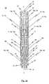
- the at least one fastening portionextends along the longitudinal axis of the stent and comprises a plurality of fastening holes distributed in a longitudinal direction at discrete positions along the length of the at least one fastening portion. Thread or thin wire may be guided through each fastening hole to secure the valvular prosthesis to the stent.
- the fastening portionmay include one or more notches to assist the seating and retaining of suture material.
- the notchesalso assist with even attachment of the prosthesis to the stent and, similarly to the fastening holes, minimise longitudinal displacement of the prosthesis.
- a fastening archover which valve tissue is laid.
- the fastening archis located inside the circumference of the stent. In this way, the prosthesis tissue is separated and held away from positioning and retaining arches, thereby reducing the likelihood of these arches chaffing the tissue which, in turn may result in damage and weakening of the prosthesis.
- the fastening archserves to anchor the lower edge of the valvular prosthesis and to tension the material so the prosthesis is effective as a valve. By having a fastening portion and fastening arches, the prosthesis is fully supported and anchored within the boundary of the stent.
- the combination of the two fastening mechanismsalso provides a failsafe should one fastening mechanism fail.
- the at least one positioning arches of the stentextends from the circumference of the stent in a generally radial direction. These positioning arches are designed to engage in the pockets of the native (diseased) cardiac valve that is being replaced which, in turn allows accurate positioning of the stent. Furthermore, on implantation, a positioning arch sits between the vascular wall and a leaflet of the native heart valve. The positioning arch then co-operates with a corresponding retaining arch resulting in clipping of the native leaflet between the two arches. In this way, the positioning and retaining arches together hold the stent in position and substantially eliminate axial rotation of the stent.
- the positioning archmay be shaped to have a substantially convex shape.
- the end of the arch that is positioned in the native valve leafletmay be curved towards the inside of the stent or towards the longitudinal axis of the stent. In this way, the shape of the each positioning arch provides an additional clipping force against the native valve leaflet.
- the at least one retaining archis connected to a positioning arch by a connecting web.
- the retaining archextends radially in the implanted state of the stent such that the at least one retaining arch presses against the wall of the blood vessel in which the stent is deployed with a radially-acting tensioning force.
- the ends of each retaining archalso fits underneath the aortic valve annulus, providing further means for locating and anchoring the stent.
- certain embodiments of the inventionprovide for the stent to further comprise at least one auxiliary arch which interconnects the respective arms of the at least one retaining arch connected to the at least one positioning arch.
- the at least one auxiliary archalso protrudes radially in the expanded state of the stent such that the at least one auxiliary arch also presses against the wall of the blood vessel in which the stent is deployed with a radially-acting tensioning force.
- the stentmay also include radial arches positioned between each positioning arch, with each radial arch extending upwards towards the distal end of the stent.
- the radial archesprovide additional means by which the stent may be retained within a catheter before and during implantation, and provide means by which the stent may be recaptured after implantation.
- the archesalso add radial strength to the distal end of the stent.
- a plurality of fastening holes and optionally one or more notchesis provided in the at least one fastening portion of the stent. These fastening holes and notches are longitudinally distributed at given positions on the fastening portion and guide at least one thread or thin wire to fasten the valvular prosthesis to the stent, thereby enabling a precise positioning of the valvular prosthesis on the stent.
- Each individual fastening hole and notch provided in the at least one fastening portionthereby serves to guide a thread or thin wire with which the valvular prosthesis is affixed or sewn to the fastening portion of the stent.
- the means provided for fastening the valvular prosthesis to the fastening portion of the stentis guided by way of the fastening holes and notches so that a longitudinal displacement of the valvular prosthesis relative to the stent is substantially minimized. This also allows exact positioning of the valvular prosthesis relative the stent.
- the secure and defined fixing of the valvular prosthesis to the at least one fastening portion of the stentmoreover effectively prevents the means used to fasten the valvular prosthesis to the stent (threads or thin wires) from rubbing against the stent and thus degrading after a longer period of use.
- the at least one fastening portionis preferably configured as—in comparison to the respective arms of the positioning arch, retaining arch and auxiliary retaining arch—a widened segment.
- a preferred realization of the stent according to a particular embodiment the inventionprovides for a fastening portion to be configured within each arm of the stent's retaining arch.
- the auxiliary archAs already mentioned above is provided.
- the auxiliary archextends from the lower ends of the fastening portion and connects the respective arms of two neighboring retaining arches.
- the stentIn manufacturing the stent used in the endoprosthesis according to a particular embodiment of the invention, it is conceivable for the stent to exhibit a structure integrally cut from a portion of tube, in particular from a small metal tube, which incorporates the positioning arches, retaining arches and auxiliary retaining arches as well as the at least one fastening portion with defined fastening holes and notches.
- a laserto cut the stent structure from the small metal tube, whereby the structure is thereafter subject to an applicable shaping and thermal treatment process so that the stent can transform from a collapsed state during implantation into an expanded state at the site of implantation.
- This shaping and thermal treatment processis advantageously performed gradually in order to prevent damage to the stent structure.
- the stentto exhibit a structure integrally cut from a small metal tube in which each positioning arch is allocated one retaining arch, and in which each upper end portion of the positioning arch towards the upper end of the stent is connected with the upper end portion of the associated retaining arch via a first connecting web.
- the at least one fastening portion, in which the plurality of fastening holes is provided,is thereby preferably configured within an arm of the retaining arch.
- the stentpreferably exhibits an integrally-formed structure which can transform from a first predefinable shape into a second predefinable shape, whereby the stent exhibits a first predefinable shape (collapsed shape) during insertion into the patient's body and a second predefinable shape (expanded shape) once implanted. Because of the stent's design, during the transition of the stent from the first predefinable shape into the second predefinable shape, the positioning arches, retaining arches and auxiliary arches are radially expanded as a function of the cross-sectional expansion of the stent.
- the stent's second shapeis thereby preferably selected such that when the stent is expanded, the retaining arch and the auxiliary arch abut against the wall of the blood vessel in which the stent is deployed.
- the ends of the retaining archesare positioned beneath the native valve annulus, thereby providing additional anchoring of the stent.
- both the retaining and auxiliary archesshould press against the wall of the vessel with a radial force, whereby this radial force can be set by subjecting the stent structure to a suitable shaping and thermal treatment process.
- the term “upper”refers to the stent when viewed in its implanted state.
- the term “upper”refers to the distal end of the stent which, when implanted, is sited away from the heart.
- use of the term “lower”refers to a proximal position on the stent which is located towards the ventricle side of the heart when the stent is viewed in its implanted position.
- a preferred embodiment of the stent according to the inventionprovides for the positioning arches and the associated retaining arches as well as auxiliary arches each to exhibit an essentially U-shaped, T-shaped or V-shaped structure which is closed toward the lower end of the stent. It is particularly preferred for each positioning arch to be cut from the material portion of a small metal tube from which the essentially U-shaped, T-shaped or V-shaped structure of the associated retaining arch was taken.
- the respective auxiliary archesare preferably cut from a material portion of the small metal tube situated between the essentially U-shaped, T-shaped or V-shaped retaining arch structures.
- This preferred embodiment of the stent structurethus provides for the respective retaining and auxiliary arches of the stent to form the lower region of the endoprosthesis, whereby the positioning arches are configured symmetrically to the retaining arches although preferably disposed somewhat further toward the upper region of the endoprosthesis.
- the respective upper ends of the positioning archesare connected to the respective upper ends of the associated retaining arches by means of a first connecting web in the upper region of the endoprosthesis.
- the fastening portionsare configured in the respective arms of the retaining arch. In the expanded state of the stent, both the lower region with the fastening portions, as well as the connecting web disposed at the upper end of the stent between the respective positioning and retaining arches, spread out so that a radially-acting force is exerted on the blood vessel wall from both the lower region of the stent as well as the upper end of the stent, thereby enabling secure anchoring of the stent at the site of implantation.
- the stentexhibits in its first shape (collapsed shape) an outer diameter of approximately 4 to 8 mm and a length of between 30 mm and 40 mm, preferably between 34.0 and 39.0 mm, and more preferably between 34.37 mm and 38.37 mm.
- Thisallows the stent to be inserted easily into the patient's body, for example with a 21 F delivery system, and to be used with a valvular prosthesis having a diameter of between 19 mm and 28 mm.
- the afore-mentioned length specificationsare the dimensions currently preferred, based on which the stent becomes suitable for the majority of patients to be treated.
- the stentIn order to achieve a particularly secure anchoring of the implanted stent with the stretched valvular prosthesis affixed thereto, it is further conceivable for the stent to be subject to a shaping and thermal treatment process during its manufacture such that the finished stent exhibits a slightly concave configuration tapering toward its lower end in its second shape.
- the lower end portion of the stenti.e., that area in which the valvular prosthesis is fastened, exhibits a somewhat tapered diameter in comparison to the upper end portion.
- the upper end of the stentexhibits a diameter approximately 10-25% larger than the diameter of its lower end, radial forces are generated particularly at the stent's upper end. This enables a secure hold of the stent in the blood vessel without damaging the arterial wall.
- This configurationalso provides secure anchoring that is able to withstand the peristaltic motion of the heart and the arterial wall.
- the somewhat lesser radial force exerted by the lower end of the stentnot only serves to anchor the stent in the blood vessel but also to stretch the valvular prosthesis attached at the lower end and reliably seal the prosthesis against the arterial wall. It is of course also conceivable to design the concave configuration of the stent in its second shape to be of greater or lesser concavity.
- the lower end area of the stentwhen in its second shape, to exhibit a diameter of between 22 mm and 33 mm, preferably between 25 mm and 31 mm. It is conceivable for the stent to exhibit two or more differently dimensioned sizes whereby the optimal stent size can be selected depending upon specific patient. In addition, exact and patient-specific dimensions of the stent—starting from a given stent size—can be realized by appropriately curing the stent, in particular by a thermal treatment process.
- the stentcomprises a valvular prosthesis, preferably a biological or pericardial valvular prosthesis, which is attached to the at least one fastening portion of the stent by means of a thread or the like.
- a shape memory materialis preferably used as the material for the stent, the material being designed such that the stent can transform from a temporary shape into a permanent shape under the influence of an external stimulus.
- the temporary shapeis thereby the stent's first shape (i.e. the collapsed state of the stent), while the permanent shape is assumed in the stent's second shape (i.e. in the expanded state of the stent).
- a shape memory materialsuch as nitinol, i.e. an equiatomic alloy of nickel and titanium, allows for a particularly gentle implantation procedure when implanting the stent.
- the stent structureWhen manufacturing the stent preferably made from a shape memory material, the stent structure is preferably shaped after it has been cut from a tube. Once the desired shape has been formed, this shape is “fixed”, this process being known as “programming”. Programming may be effected by heating the stent structure, forming the stent into the desired shape and then cooling the stent. Programming may also be effected by forming and shaping the stent structure at lower temperature, this being known as “cold stretching.” The permanent shape is thus saved, enabling the stent to be stored and implanted in a temporary, non-formed shape. If an external stimulus then acts on the stent structure, the shape memory effect is activated and the saved, permanent shape restored.
- a particularly preferred embodimentprovides for the external stimulus to be a definable switching temperature. It is thus conceivable that the stent material needs to be heated to a higher temperature than the switching temperature in order to activate the shape memory effect and thus regenerate the saved permanent shape of the stent.
- a specific switching temperaturecan be preset by the relevant selection of the chemical composition of the shape memory material.
- the switching temperatureis in the range of between room temperature and the patient's body temperature. Doing so is of advantage, especially with regard to the medical device being used as an implant in a patient's body. Accordingly, all that needs to be ensured in this regard when implanting the stent is that the stent is warmed up to the patient's body temperature (36° C.) at the site of implantation to activate the shape memory effect of the stent material.
- FIG. 1 aa perspective side view of a cardiac valve stent in accordance with a first embodiment of the invention, where the cardiac valve stent is shown in its collapsed state;
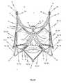
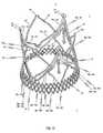
- FIG. 1 ba perspective side view of the cardiac valve stent in accordance with the first embodiment of the invention, where the cardiac valve stent is shown in its expanded state;
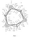
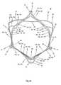
- FIG. 1 ca perspective top plan view of the proximal end of the cardiac valve stent in accordance with the first embodiment of the invention, where the cardiac valve stent is shown in its expanded state;
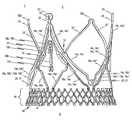
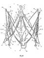
- FIG. 1 da perspective side view of an endoprosthesis for treating a narrowed cardiac valve or a cardiac valve insufficiency, where the endoprosthesis comprises the cardiac valve stent according to the first embodiment of the invention for holding a valvular prosthesis;
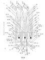
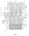
- FIG. 1 ea two-dimensional projection of a cutting pattern applicable to manufacturing the cardiac valve stent according to the first embodiment of the invention in order to cut a cardiac valve stent pursuant to FIG. 1 a integrally from a portion of tube, in particular a small metal tube;
- FIG. 2 aa perspective side view of a cardiac valve stent according to a second embodiment of the invention, where the cardiac valve stent is shown in its collapsed state;
- FIG. 2 ba first perspective side view of the cardiac valve stent according to the second embodiment of the invention, whereby the cardiac valve stent is shown in its expanded state;
- FIG. 2 ca second perspective side view of the cardiac valve stent according to the second embodiment of the invention, where the cardiac valve stent is shown in its expanded state;
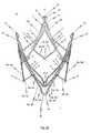
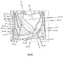
- FIG. 2 da perspective side view of an endoprosthesis for treating a narrowed cardiac valve or a cardiac valve insufficiency, where the endoprosthesis comprises the cardiac valve stent according to the second embodiment of the invention for holding a valvular prosthesis;
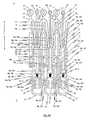
- FIG. 2 ea two-dimensional projection of a cutting pattern for manufacturing the cardiac valve stent according to the second embodiment of the invention to enable a cardiac valve stent pursuant FIG. 2 a to be cut integrally from a portion of a tube, in particular a small metal tube;
- FIG. 3a two-dimensional projection of a cutting pattern for manufacturing a cardiac valve stent according to the third embodiment of the invention to enable a cardiac valve stent to be cut integrally from a portion of a tube, in particular a small metal tube;
- FIG. 4a two-dimensional projection of a cutting pattern for manufacturing a cardiac valve stent according to the fourth embodiment of the invention to enable a cardiac valve stent to be cut integrally from a portion of a tube, in particular a small metal tube;
- FIG. 5 aa first perspective side view of the cardiac valve stent according to the fifth embodiment of the invention, whereby the cardiac valve stent is shown in its expanded state;
- FIG. 5 ba second perspective side view of the cardiac valve stent according to the fifth embodiment of the invention, whereby the cardiac valve stent is shown in its expanded state;
- FIG. 5 ca top view of the upper end of the cardiac valve stent according to the fifth embodiment of the invention, whereby the cardiac valve stent is shown in its expanded state;
- FIG. 5 da two-dimensional projection of a cutting pattern applicable to manufacturing a cardiac valve stent according to the fifth embodiment of the invention in order to cut a cardiac valve stent pursuant to FIG. 5 a integrally from a portion of tube, in particular a small metal tube;
- FIG. 6 aa first perspective side view of the cardiac valve stent according to the sixth embodiment of the invention, whereby the cardiac valve stent is shown in its expanded state;
- FIG. 6 ba second perspective side view of the cardiac valve stent according to the sixth embodiment of the invention, whereby the cardiac valve stent is shown in its expanded state;
- FIG. 6 ca third perspective side view of the cardiac valve stent according to the sixth embodiment of the invention, whereby the cardiac valve stent is shown in its expanded state;
- FIG. 6 da two-dimensional projection of a cutting pattern applicable to manufacturing a cardiac valve stent according to the sixth embodiment of the invention in order to cut a cardiac valve stent pursuant to FIG. 6 a integrally from a portion of a tube, in particular a small metal tube;
- FIG. 6 ea perspective side view of an endoprosthesis for treating a narrowed cardiac valve or a cardiac valve insufficiency, where the endoprosthesis comprises the cardiac valve stent according an embodiment of the invention for holding a valvular prosthesis, whereby the cardiac valve stent is shown in a partly expanded state;
- FIG. 6 fa perspective side view of an endoprosthesis for treating a narrowed cardiac valve or a cardiac valve insufficiency, where the endoprosthesis comprises the cardiac valve stent according to the sixth embodiment of the invention for holding a valvular prosthesis, whereby the cardiac valve stent is shown in an expanded state;
- FIG. 6 ga perspective detail view of the head portion of a retaining arch belonging to the cardiac valve stent of the endoprosthesis shown in FIG. 6 f;
- FIG. 6 ha perspective detail view of an additional fastening portion belonging to the cardiac valve stent of the endoprosthesis shown in FIG. 6 f;
- FIG. 6 ia top view of the lower end of the endoprosthesis shown in FIG. 6 f;
- FIG. 7 aa two-dimensional projection of a cutting pattern for manufacturing a cardiac valve stent according to the seventh embodiment of the invention to enable a cardiac valve stent to be cut integrally from a portion of a tube, in particular a small metal tube;
- FIG. 7 ba first perspective side view of the cardiac valve stent according to the seventh embodiment of the invention, whereby the cardiac valve stent is shown in its expanded state;
- FIG. 7 ca second perspective side view of the cardiac valve stent according to the seventh embodiment of the invention, whereby the cardiac valve stent is shown in its expanded state;
- FIG. 8 aa two-dimensional projection of a cutting pattern for manufacturing a cardiac valve stent according to the eighth embodiment of the invention to enable a cardiac valve stent to be cut integrally from a portion of a tube, in particular a small metal tube;
- FIG. 8 ba first perspective side view of the cardiac valve stent according to the eighth embodiment of the invention, whereby the cardiac valve stent is shown in its expanded state;
- FIG. 8 ca second perspective side view of the cardiac valve stent according to the eighth embodiment of the invention, whereby the cardiac valve stent is shown in its expanded state;
- FIG. 9 aa two-dimensional projection of a cutting pattern for manufacturing a cardiac valve stent according to the ninth embodiment of the invention to enable a cardiac valve stent to be cut integrally from a portion of a tube, in particular a small metal tube;
- FIG. 9 ba perspective side view of the cardiac valve stent according to the ninth embodiment of the invention, whereby the cardiac valve stent is shown in its expanded state;
- FIG. 10a two-dimensional projection of a cutting pattern for manufacturing a cardiac valve stent according to the tenth embodiment of the invention to enable a cardiac valve stent to be cut integrally from a portion of a tube, in particular a small metal tube;
- FIG. 11a two-dimensional projection of a cutting pattern for manufacturing a cardiac valve stent according to the eleventh embodiment of the invention to enable a cardiac valve stent to be cut integrally from a portion of a tube, in particular a small metal tube;
- FIG. 12 a - ca process sequence illustrating a transarterial implantation of an endoprosthesis comprising a cardiac valve stent in accordance with certain embodiments of the invention.
- Both the right and left halves of the human heartconsist of a ventricle and an atrium. These cavities are separated by the septum of the heart, divided into the atrial septum (septum interatriale) and the ventricular septum (septum interventriculare). Blood can only flow in one direction through the chambers of the heart due to the cardiac valves situated between the atria and ventricles and in the arteries connected to the ventricles which function like mechanical valves.
- the superior and inferior vena cava(vena cava superior et inferior) flow into the right atrium. They supply the oxygen-depleted (venous) blood from the systemic circulation to the heart.
- the tricuspid valvewhich, like a mechanical valve, prevents a reverse flow of blood into the atrium upon ventricular contraction (systole) is situated between the right atrium and the right ventricle. It comprises three segments which are affixed like flaps to the ventricular musculature by ligaments (hence also called the “flap valve”).
- the two pulmonary arteriesdepart the right ventricle of the heart via a common trunk (truncus pulmonalis). There is also a valve between the ventricle and the pulmonary trunk, the so-called pulmonary valve. This type of valve is also called a semilunar valve due to its shape.
- the pulmonary arteriessupply the oxygen-depleted blood to the pulmonary circulation.
- Oxygen-rich (arterial) bloodthen usually flows through four pulmonary veins from the pulmonary circulation to the left atrium. From there, it reaches the left ventricle through a further flap valve, the mitral valve. The outflow is carried by the aorta which, like the pulmonary artery, has a semilunar valve (aortic valve).
- aortawhich, like the pulmonary artery, has a semilunar valve (aortic valve).
- the atriafill first while the ventricles concurrently disgorge the blood into the arteries.
- the flap valvesopen due to the drop in pressure in the ventricle and the blood flows in from the atria (auricular systole). This is supported by a contraction of the atria.
- Ventricular contractionfollows: the ventricular musculature contracts, the pressure rises, the flap valves close and the blood can now only flow into the arteries through the now-opened semilunar valves.
- a reverse blood flow from the arteries during the relaxation phase (diastole)is prevented by the closing of the semilunar valves such that the direction of flow is determined solely by the valves.
- the four cardiac valveswork like mechanical valves in the heart and prevent a reverse flow of blood in the wrong direction.
- Each half of the hearthas a flap valve (atrioventricular valve) and a semilunar valve.
- the atrioventricular valvesare situated between the atrium and the ventricle and are called the bicuspid/mitral valve and the tricuspid valve.
- the semilunar valvesare situated between the ventricle and the vascular outflow and are called the pulmonary valve and the aortic valve respectively.
- a valve defecti.e. a dysfunction of a cardiac valve's function
- Dysfunctioncan encompass constriction (stenosis), insufficiency or a combination of the two (combined vitium).
- aortic valve insufficiencyrefers to the defective closing of the heart's aortic valve and the diastolic reverse flow of blood from the aorta into the left ventricle as a result.
- the volume of reverse flowcan be up to two thirds of the left ventricle's ejection volume (normal cardiac output 40 to 70 ml). This results in characteristically high blood pressure amplitude.
- This regurgitate blood flowincreases the diastolic filling of the left chamber and leads to a volume overload of this section of the heart, a consequence of which is eccentric hypertrophy.
- Aortic valve stenosisis a valvular heart disease caused by the incomplete opening of the aortic valve.
- the aortic valvebecomes stenotic, it causes a pressure gradient between the left ventricle and the aorta.
- the more constricted the valvethe higher the gradient between the left ventricle and the aorta.
- the gradientmay be 20 mmHg. This means that, at peak systole, while the left ventricle may generate a pressure of 140 mmHg, the pressure that is transmitted to the aorta will only be 120 mm Hg.
- the left ventricleIn individuals with aortic valve stenosis, the left ventricle has to generate an increased pressure in order to overcome the increased after load caused by the stenotic aortic valve and eject blood out of the left ventricle.
- the myocardium (muscle) of the left ventricleundergoes hypertrophy (increase in muscle mass).
- Angina in the setting of aortic valve stenosisis secondary to the left ventricular hypertrophy that is caused by the constant production of increased pressure required to overcome the pressure gradient caused by the aortic valve stenosis. While the myocardium (i.e. heart muscle) of the left ventricle gets thicker, the arteries that supply the muscle do not get significantly longer or bigger, so the muscle may become ischemic (i.e. doesn't receive an adequate blood supply). The ischemia may first be evident during exercise, when the heart muscle requires increased blood supply to compensate for the increased workload. The individual may complain of exertional angina. At this stage, a stress test with imaging may be suggestive of ischemia.
- myocardiumi.e. heart muscle
- Mitral valve insufficiency(also called mitral insufficiency) is a frequent cardiac valve defect in human medicine and also in at least some animal species. It involves a closing defect or “leakage” of the heart's mitral valve which leads to reverse blood flow from the left ventricle into the left atrium during the ejection phase (systole).
- the mitral valvefunctions like a mechanical valve between the left atrium and the left ventricle of the heart. It opens during the filling phase of the ventricle (diastole) and thus enables the inflow of blood from the atrium.
- the sudden increase in pressure in the ventricleleads to the closing of the valve and thus to a “sealing” of the atrium.
- a pressure of only about 8 mmHgprevails in the atrium, while at the same time the systolic pressure of about 120 mmHg in the ventricle forces the blood along its usual path into the main artery (aorta).
- the regurgitation openingis larger than 40 mm 2 and the regurgitation volume greater than 60 ml, which can lead to serious and at times life-threatening changes.
- a valvular prosthesisTo treat a severe narrowed cardiac valve or cardiac valve insufficiency, it is necessary for a valvular prosthesis to perform the valve function of the narrowed, diseased or diseased cardiac valve.
- Essential in this respectis that the valvular prosthesis is securely positioned and anchored in the implantation site in the heart; i.e. in the plane of the (diseased) cardiac valve to be replaced, so that the valvular prosthesis is not displaced or shifted despite the, at times considerable, forces acting on it.
- An effective seal during systoleis also important.
- a cardiac valve stent 10to which the valvular prosthesis 100 is appropriately affixed, is employed in accordance with at least certain embodiments of the invention to position and anchor said valvular prosthesis.
- a medical device for the treating of a narrowed cardiac valve or a cardiac valve insufficiency consisting of a cardiac valve stent 10 and a valvular prosthesis 100 affixed to the stent 10will be referred to herein simply as endoprosthesis 1 .
- FIG. 1 dshows a perspective side view of such an endoprosthesis 1 for treating a narrowed cardiac valve or a cardiac valve insufficiency, whereby the endoprosthesis 1 comprises a cardiac valve stent 10 to hold a valvular prosthesis 100 in accordance with a first embodiment of the invention.
- FIG. 2 dlikewise shows a perspective side view of a further endoprosthesis 1 for treating a narrowed cardiac valve or a cardiac valve insufficiency, whereby a cardiac valve stent 10 in accordance with a second embodiment of the invention is employed.
- the cardiac valve stent 10exhibits an expandable structure which is able to transform from a first predefinable shape in which the stent 10 is in a collapsed state into a second predefinable shape in which the stent 10 is in an expanded state.
- FIG. 1 ashows a side view of the stent 10 according to the first embodiment of the invention, whereby the stent 10 is in its collapsed state.
- FIG. 2 ashows the collapsed stent 10 according to a second embodiment of the invention.
- the stent 10is introduced in a minimally-invasive fashion into the body of a patient in its first shape (cf. FIG. 1 a and FIG. 2 a ) using an insertion catheter system (not explicitly shown in the drawings).
- a valvular prosthesis 100 affixed to the stent 10is likewise in a collapsed state.
- FIGS. 1 a and 2 adispense with a representation of the valvular prosthesis 100 affixed to the stent 10 .
- the stent 10Upon reaching the site of implantation in the patient's heart, the stent 10 transforms, through increments, into its second (expanded) shape in which also the valvular prosthesis 100 affixed to the stent 10 also unfolds and expands.
- the second, expanded shapeis a permanent shape that has been set by programming.
- the completely expanded stent 10 according to the first/second embodiment of the invention with the likewise completely unfolded and expanded valvular prosthesis 100 affixed theretois shown in FIG. 1 d and FIG. 2 d.
- FIG. 1 b and FIG. 1 cshow the completely expanded stent 10 according to the first embodiment of the invention from different perspectives without the valvular prosthesis 100 .
- FIGS. 2 b and 2 cshow the completely expanded stent 10 according to the second embodiment of the invention, likewise without the valvular prosthesis 100 , from different perspectives.
- FIGS. 1 a to 1 eThe following will initially make reference to FIGS. 1 a to 1 e in describing the first embodiment of the stent 10 .
- the stent 10 according to the first embodimentexhibits a structure integrally cut from a portion of tube, in particular a small metal tube.
- the cutting pattern used to form the design of the stentis depicted in a two-dimensional projection in FIG. 1 e.
- the stent 10has three positioning arches 15 a , 15 b , 15 c which assume the function of self-positioning the stent into the plane of the pulmonary valve (valva trunci pulmonalis) or aortic valve (valva aortae).
- the positioning arches 15 a , 15 b , 15 cexhibit a rounded head portion 20 which engages in the pockets T of the (diseased) cardiac valve to be treated during positioning of the stent 10 at the site of implantation in the heart (cf. FIG. 12 a ).
- the provision of three positioning arches 15 a , 15 b , 15 calso provides rotational accuracy, symmetry and stability.
- the stent 10is of course not limited to the use of a total of three positioning arches.
- the head portions 20 of the positioning arches 15 a , 15 b , 15 care rounded so that the vascular wall will not be damaged when the positioning arches 15 a , 15 b , 15 c engage in the pockets T of the cardiac valve H to be replaced.
- reference markers 21are provided on or within the head portions 20 of the positioning arches 15 a , 15 b , 15 c . Radio opaque markers or markers which can be activated by infrared or ultrasound lend themselves particularly well hereto.
- each positioning arch 15 a , 15 b , 15 crespectively exhibit an essentially U-shaped or V-shaped structure which is closed to the lower end of stent 10 . Accordingly, each positioning arch 15 a , 15 b , 15 c has a total of two arms 15 a ′, 15 a ′′, 15 b ′, 15 b ′′, 15 c ′, 15 c ′′ respectively extending from the head portion 20 of the associated positioning arch 15 a , 15 b , 15 c towards the upper end 3 of stent 10 . By doing so, each two adjoining arms of two neighbouring positioning arches are connected to one another via a connecting portion 22 .
- the stent 10For implanting and explanting the stent 10 with a suitable catheter system, the stent 10 comprises catheter retaining means 23 at its upper end 3 .
- the connecting portions 22are respectively connected to catheter retaining means 23 via a connecting web 25 .
- the connecting webs 25will hereinafter be referred to as “second connecting web 25 ”.
- the catheter retaining means 23comprise oval-shaped heads which each comprise a corresponding oval-shaped eyelet 24 .
- the shape of the catheter retaining means 23complements a crown on the tip of a catheter of a catheter system used to implant/explant stent 10 .
- the crown on the catheter tiphas protruding elements that are configured as a negative of the catheter retaining means 23 .
- the protruding elementsare shaped to be complementary to the eyelets 24 and are configured as catheter retaining heads. This realization enables the protruding elements of the crown to form a releasable engagement with the upper area 3 of stent 10 to allow releasable attachment of the stent 10 to the tip of the catheter.
- a first connecting web 17extends essentially in the longitudinal direction L of stent 10 and has an upper end portion 17 d and a lower end portion 17 p .
- the upper end portion 17 dopens into connecting portion 22 between the two arms 15 a ′, 15 a ′′, 15 b ′, 15 b ′′, 15 c ′, 15 c ′′ of two neighboring positioning arches 15 a , 15 b , 15 c , in addition to the previously-mentioned second connecting web 25 .
- the first connecting webs 17have an essentially inverted Y-shaped configuration and each exhibit a structure that diverges at its lower end portion 17 p to give way to the respective arms 16 a ′, 16 a ′′, 16 b ′, 16 b ′′, 16 c ′, 16 c ′′ of two neighboring retaining arches 16 a , 16 b , 16 c.
- each positioning arch 15 and retaining arch 16is a fastening arch 19 .
- the fastening archdepends from the proximal end of fastening portion 11 and has a substantially U-shaped or V-shaped structure which is closed to the lower end of stent 10 .
- the fastening archesserve to support the lower end of valve prosthesis 100 .
- the prosthesis 100is shaped so that fastening arches 191 , 19 b and 19 c are located in pockets of the valve material.
- the fastening arches 19 a , 19 b and 19 chave a longitudinal shape that allows the arches to lie in line with the circumference of the stent 10 . In this way, the arches 19 sit inside the positioning and retaining arches, thereby holding the valve material away from the stent structure. This reduces wear on the valve material by the stent once the prosthesis 1 has been implanted.
- This stent designachieves an axially symmetrical structure, whereby each positioning arch 15 a , 15 b , 15 c is allocated one fastening arch 19 a , 19 b , 19 c and one retaining arch 16 a , 16 b , 16 c .
- the stent 10 of the first embodiment depicted in FIGS. 1 a to 1 dthus comprises a total of three retaining arches 16 a , 16 b , 16 c which constitutes a retaining segment of stent 10 for accommodating a valvular prosthesis 100 as depicted for example in FIG. 1 d.
- FIG. 1 bin which the stent 10 pursuant to the first embodiment is shown in its second, expanded shape. It can be particularly recognized from this representation that each positioning arch 15 a , 15 b , 15 c and associated fastening arch 19 a , 19 b , 19 c and retaining arch 16 a , 16 b , 16 c respectively exhibit an essentially U-shaped or V-shaped structure which is closed towards the lower end 2 of the stent 10 .
- each positioning arch 15 a , 15 b , 15 cis cut from a material section of a portion of a tube from which the essentially U-shaped or V-shaped structure of the associated fastening arch 19 a , 19 b , 19 c was taken, as can be seen from the cutting pattern depicted in FIG. 1 e.
- FIG. 1 aA comparison of FIG. 1 a to FIG. 1 b shows that, upon the stent 10 expanding; i.e. when the stent 10 transforms from its first shape into its second shape, the stent 10 shortens in the longitudinal direction L while simultaneously enlarging in cross-section.
- the positioning arches 15 a , 15 b , 15 care expanded more in the radial direction at the lower end 2 of the stent 10 compared to the upper end 3 of stent 10 . Since they protrude more in the radial direction, the positioning arches 15 a , 15 b , 15 c can be deployed into the cardiac valve pockets T of the cardiac valve H to be replaced in a particularly easy manner.
- the retaining arches 16 a , 16 b , 16 cprotrude radially from the circumference of the stent 10 in its expanded state such that the retaining arches 16 a , 16 b , 16 c press against the wall of the blood vessel in which the stent is deployed with a radially-acting contact force.
- the closed ends of the retaining arches 16 a , 16 b , 16 cflare outwards, protruding radially still further from the circumference of the stent 10 . This shape allows the ends of the retaining arches 16 a , 16 b , 16 c to be positioned below the native valve annulus or to be positioned at least on the native valve annulus, thereby providing additional anchoring for the stent 10 .
- the stent 10further comprises auxiliary arches 18 a , 18 b , 18 c , which likewise exert a radially-acting contact force against the wall of the blood vessel in the implanted state of stent 10 , thereby further improving anchoring of stent 10 at the site of implantation.
- stent 10comprises a total of three essentially U-shaped or V-shaped auxiliary arches 18 a , 18 b , 18 c which are closed towards the lower end 2 of said stent 10 .
- Each auxiliary arch 18 a , 18 b , 18 cconnects a first retaining arch 16 a , 16 b , 16 c with a second retaining arch neighboring the first retaining arch.
- the lower end region 2exhibits a dodecagonal polygonal structure formed from the individual arms 16 a ′, 16 a ′′, 16 b ′, 16 b ′′, 16 c ′, 16 c ′′ of retaining arches 16 a , 16 b , 16 c and the individual arms 18 a ′, 18 a ′′, 18 b ′, 18 b ′′, 18 c ′, 18 c ′′ of the auxiliary arches 18 a , 18 b , 18 c .
- This stent designparticularly provides a total of six arches 16 a , 16 b , 16 c , 18 a , 18 b , 18 c uniformly distributed around the lower end region 2 of stent 10 , each of which press against the vascular wall and effectively hold the stent 10 in position in the expanded and implanted state of stent 10 .
- the upper end region 3 of stent 10In addition to the contact force exerted on the vascular wall by way of the retaining arches 16 a , 16 b , 16 c and auxiliary arches 18 a , 18 b , 18 c , it is conceivable for the upper end region 3 of stent 10 to expand radially 10% to 25% more—in the expanded state of stent 10 —compared to the lower end region 2 . This gives the stent 10 a slight concave structure which tapers towards the lower end region 2 . This ensures secure anchoring of the stent 10 within the vessel by the upper end region 2 of the stent 10 pressing against the vascular wall.
- the embodiment of the inventive stent 10 depicted in the drawingsprovides for the stent 10 to comprise a plurality of fastening portions 11 extending in the longitudinal direction L of stent 10 , by means of which a valvular prosthesis 100 is affixed to the stent 10 .
- FIG. 1 dshows a perspective side view of an endoprosthesis 1 for treating a narrowed cardiac valve or a cardiac valve insufficiency.
- the endoprosthesis 1comprises the stent 10 pursuant the first embodiment of the invention holding a valvular prosthesis 100 .
- the valvular prosthesis 100comprises at least one valve flap 102 made from a biological or synthetic material.
- valvular prosthesismay be made from any suitable material, including biological valves removed from animals such as pigs and horses, man-made biological valves created from connective tissue such as pericardium, tissue grown from cell cultures, and man-made materials and fabrics such as nitinol.
- first connecting webs 17 of stent 10connect with connecting portions 22 via their upper ends 17 d and with the upper ends 13 of fastening portions 11 via their lower ends 17 p .
- the respective lower ends 14 of the fastening portions which are connected to one and the same connecting web 17are thereby connected together via an essentially U-shaped or V-shaped auxiliary arch 18 a , 18 b , 18 c which is closed towards the lower end 2 of stent 10 .
- FIG. 1 dthe first embodiment of the inventive stent 10 is shown in FIG. 1 d in its expanded state, whereby a valvular prosthesis 100 is fastened to said stent 10 by means of a thread 101 or a thin wire and stretched by the stent 10 .
- a valvular prosthesis 100is fastened to said stent 10 by means of a thread 101 or a thin wire and stretched by the stent 10 .
- the widening of the centre area and the lower end region 2 of stent 10 at which the valvular prosthesis 100 is disposedachieves spreading of the valvular prosthesis.
- the lower end portions of the retaining arches 16 a , 16 b , 16 c and the auxiliary arches 18 a , 18 b , 18 cexert a radial force on the (not shown in FIG. 1 d ) vascular wall.
- a defined plurality of fastening holes 12are configured in the respective fastening portions 11 of stent 10 , and are arranged to be distributed at predefined longitudinal positions along the fastening portions 11 .
- the thread 101 or thin wire with which the valvular prosthesis 100 is attached to stent 10is guided through each respective fastening hole 12 .
- Both components constituting the endoprosthesis 1namely the stent 10 and the valvular prosthesis 100 , are preferably not connected together until directly prior to the surgical procedure.
- the respective fastening portions 11are configured in the respective arms 16 a ′, 16 a ′′, 16 b ′, 16 b ′′, 16 c ′, 16 c ′′ of retaining arches 16 a , 16 b , 16 c of stent 10 .
- the size of the fastening holes 12 configured in the fastening portions 11should be adapted to the thickness of the thread 101 or wire used to fasten the valvular prosthesis 100 to the stent 10 .
- the cross-sectional shape to the fastening holes 12may also be adapted to the cross-sectional shape of the thread 101 or wire used to fasten the valvular prosthesis 100 . This allows fixing of the valvular prosthesis 100 to the stent 10 at a precise predefined position relative to the stent 10 . By providing of a plurality of fastening holes 12 to anchor the valvular prosthesis 100 to the stent 10 , precise positioning of the valvular prosthesis on stent 10 is achieved.
- the fastening holes 12are adapted to the thickness and/or the cross-sectional shape of the thread 101 or wire used to affix the valvular prosthesis 100 to the stent 10 , relative movement between the stent 10 and the valvular prosthesis 100 due to the peristaltic motion of the heart can be effectively prevented when the endoprosthesis 1 is implanted.
- the valvular prosthesis 100is thus fastened to the stent 10 with minimal play, based on which friction-induced wear of the thread 101 or wire used to affix the valvular prosthesis is minimized.
- the fastening holes 12have a circular cross-sectional shape.
- the fastening holes 12 configured in the respective fastening portions 11may be of different diameters, numbers or cross-sectional shapes (oval, square, etc) according to the diameter of a thread 101 used for affixing the valvular prosthesis 100 to the stent 10 , and/or according to the sewing technique utilized for affixing the valvular prosthesis 100 to the stent 10 .
- the diameter, number and/or cross-sectional shape of at least one of the fastening holes 12may also serve as an indication of the type of the endoprosthesis 1 , i.e. the medical device used in the treatment of a narrowing of a cardiac valve and/or a cardiac valve insufficiency.
- the diameter, number and/or cross-sectional shape of the at least one fastening hole 12may be used for identification to differentiate between different sizes or types of valvular prostheses 100 adapted to be fixed on the stent 10 , or may be used for identification to differentiate between different sizes or types of endoprostheses 1 , if a valvular prosthesis 100 is already fixed to the stent 10 .
- a small-sized stent 10 having a small-sized valvular prosthesis 100 fixed thereto or a small-sized stent 10 adapted and configured for carrying a small-sized valvular prosthesis 100could have circular fastening holes 12 whilst a large-sized stent 10 having a large-sized valvular prosthesis 100 fixed thereto or a large-sized stent 10 adapted and configured for carrying a large-sized valvular prosthesis 100 may have triangular fastening holes 12 . This allows the surgeon/cardio staff to easily and visually tell different valve sizes, stent types and/or types of the endoprosthesis apart without the need to measure.
- the fastening portions 11 of the stent 10do not change their shape when the stent 10 is compressed, e.g. when the stent 10 is in its first (collapsed) shape shown in FIG. 1 a .
- This phenomenonoccurs when standard tube stents are used. Thus the risk of thread wear is minimal.
- FIGS. 2 a to 2 cA stent 10 in accordance with a second embodiment is depicted in FIGS. 2 a to 2 c and is similar in structure and function to the first embodiment of the stent 10 depicted in FIGS. 1 a to 1 c .
- the samealso holds true for the cutting pattern depicted in FIG. 2 e which is, in principle, comparable to the cutting pattern according to FIG. 1 e .
- a detailed description of the common featureswill therefore not be provided.
- a difference to be seenis in the configuration of the catheter retaining means 23 provided at the distal end 3 of stent 10 .
- heads of an essentially round configurationare used as catheter retaining means 23 in the second embodiment, in each case provided with essentially oval eyelets 24 . Due to the round configuration of the heads the risk of producing injury or damage is lowered. Hence, an essentially round configuration of the heads is more atraumatic.
- the stent 10preferably exhibits a structure integrally cut from a portion of tube, and in particular from a small metal tube.
- a fastening arch 19 a , 19 b , 19 c and a retaining arch 16 a , 16 b , 16 cis allocated to each positioning arch 15 a , 15 b , 15 c , and each retaining arch 16 a , 16 b , 16 c is connected to a neighboring retaining arch by means of an auxiliary arch 18 a , 18 b , 18 c .
- a fastening portion 11 with a specific number of fastening holes 12is configured in each arm 16 a ′, 16 a ′′, 16 b ′, 16 b ′′, 16 c ′, 16 c ′′ of retaining arch 16 a , 16 b , 16 c.
- FIGS. 1 e and 2 eeach show a two-dimensional projection of a cutting pattern which can be used in the manufacture of the stent 10 pursuant the first or second embodiment of the invention. This enables a one-piece stent 10 to be cut from a portion of tube, in particular a small metal tube. It is evident that, on the one hand, the inventive stent 10 dispenses with fixed-body joints or other similar connective devices between the individual components of stent 10 (positioning arch, retaining arch, auxiliary arch).
- a stent 10which exhibits, with minimum longitudinal extension, the functionality of positionability as provided by the positioning arches 15 a , 15 b , 15 c on the one hand and, on the other, the functionality of the defined fastening of a valvular prosthesis 100 , as provided by the fastening portions 11 configured in the respective arms 16 a ′, 16 a ′′, 16 b ′, 16 b ′′, 16 c ′, 16 c ′′ of the retaining arch 16 a , 16 b , 16 c.
- the stent 10further comprises auxiliary arches 18 a , 18 b , 18 c which enable a particularly secure anchoring of stent 10 in the site of implantation in the heart.
- a stent 10 according to a third embodiment of the inventionalso has a one-piece structure cut from a portion of a tube, in particular from a small metal tube.
- the cutting pattern used to form the stent designis shown in a two-dimensional projection in FIG. 3 .
- the third embodiment of the stent 10has a total of three positioning arches 15 a , 15 b , 15 c , which undertake the function of automatic positioning of the cardiac valve stent in the plane of the pulmonary valve or the aortic valve.
- the stent 10is made from nitinol and positioning arches 15 a , 15 b , 15 c are programmed during manufacture, by a suitable heat treatment of the positioning arches 15 a , 15 b , 15 c , so that, in the stent's expanded state i.e. when the permanent shape has been assumed after exceeding the switching temperature, the positioning arches not only spread apart in a radial direction, as illustrated in FIGS. 1 b , 1 d and 2 b , 2 d , but simultaneously curve in a slightly convex manner in the direction of the stent 10 .
- the head portions 20 of the positioning arches 15 a , 15 b , 15 cmake it possible for the head portions 20 of the positioning arches 15 a , 15 b , 15 c to lie parallel with the longitudinal axis L of the expanded stent 10 in an ideal manner.
- the head portions 20 of the positioning arches 15 a , 15 b , 15 ccan be inserted particularly easily into the pockets T of the native heart valve H (see FIG. 12 a ).
- thisminimizes damage to surrounding tissue when the positioning arches 15 a , 15 b , 15 c are inserted into the pockets T of the native heart valve H.
- the shapealso allows the positioning arches 15 a , 15 b , 15 c to exert an additional clipping force on the native valve leaflets by pinching the native leaflet at the bottom of each arch.
- the convex curvature of the positioning arches 15 a , 15 b , 15 cenables an especially secure support of the stent 10 at the implantation site since the positioning arches 15 a , 15 b , 15 c are better adapted to the anatomy of the pockets T of the native heart valves H and their surroundings.
- a stent 10 of the third embodimenthas catheter retaining means 23 with eyelets 24 .
- a suitable catheter systemcan be releasably coupled to the catheter retaining means 23 to facilitate a minimally-invasive, transvascular implantation and explantation of the stent 10 .
- the retaining arches 16 a , 16 b , 16 c and auxiliary arches 18 a , 18 b , 18 cserve to secure radial fixing of the stent 10 at the implantation site and for stretching a valvular prosthesis fastened to the stent by way of fastening arches 19 a , 19 b , 19 c .
- the retaining arches 16 a , 16 b , 16 c and the auxiliary arches 18 a , 18 b , 18 c of this embodiment of the stentalso function to seal an implanted valvular prosthesis.
- the retaining arches 16 a , 16 b , 16 c and positioning arches 15 a , 15 b , 15 cclamp the native heart valve H like a paperclip and consequently contribute to the secure anchoring of the stent 10 at the implantation site in the heart.
- Stent 10differs from the first and second embodiments in that the respective arms 16 a ′, 16 a ′′, 16 b ′, 16 b ′′, 16 c ′, 16 c ′′ of each retaining arch 16 a , 16 b , 16 c extend from the fastening portion 11 to the lower end 2 of the cardiac valve stent and are connected together by means of a connecting portion 30 .
- the connecting portion 30has a different shape when compared with the U-shaped or V-shaped connecting portions 30 in the embodiments according to FIGS. 1 b , 1 c , 1 d and 2 b , 2 c , 2 d .
- the connecting portion 20has a waist just above the corresponding connecting portion 30 ′ of the fastening arch.
- the waists in the retaining and fastening archesaccommodate an enlarged head 31 at the lower end of each auxiliary arch 18 a , 18 b , 18 c.
- each connecting portion 30which connects the two arms 16 a ′, 16 a ′′, 16 b ′, 16 b ′′, 16 c ′, 16 c ′′ of a retaining arch 16 a , 16 b , 16 c has almost an O-shaped configuration.
- This shapeoffers more space for fastening a valvular prosthesis 100 to the stent 10 and also effectively counteracts the occurrence of load peaks which can occur in the implanted state of the endoprosthesis during the transmission of loads between the valvular prosthesis and the stent.
- the alternative shape of the connecting portion 30further increases the effective contact area between the lower end of the retaining arch 16 a , 16 b , 16 c and the vessel wall, when the stent is positioned at the implantation site in its expanded state. Because of this, an improved seal can be obtained between the stent with the valvular prosthesis attached to it and the vessel wall. Furthermore, the radial forces acting in the expanded state of the stent, which are transmitted via the retaining arches 16 a , 16 b , 16 c to the vessel wall, are distributed over a discrete contact area, thereby counteracting the occurrence of load peaks. The risk of damage from the retaining arches 16 a , 16 b , 16 c to the vessel wall is also reduced.
- Each connecting portion 30 ′which connects the two arms 19 a ′, 19 a ′′, 19 b ′, 19 b ′′, 19 c ′, 19 c ′′ of a fastening arch 19 a , 19 b , 19 c has a more angular shape that assists with anchoring of a valvular prosthesis 100 to the stent 10 .
- the alternative shapes of the closed ends of the retaining and fastening archesaccommodates the enlarged heads 31 of shortened auxiliary arches 18 a , 18 b , 18 c .
- the enlarged head 31enables the auxiliary arches to be used to support the valve material 100 , as well as providing additional radial force.
- the heads 31include fastening holes 12 for additional attachment of the prosthetic valve 100 which further stabilizes the prosthetic valve 100 attached to the stent.
- the additional fastening holes 12also reduce the likelihood of mis-aligning the valve 100 within the stent 10 and minimize any longitudinal movement of the valve 100 once the endoprosthesis 1 has been implanted.
- an enlarged contact areais provided with the widened head portions 31 , which improves the anchorage of the stent 10 at the implantation site while minimizing the risk of damage to the vessel wall.
- the upper arm portions of the respective retaining arches 16 a , 16 b , 16 care connected to the lower region 14 of the associated fastening portion 11
- the upper arm portions of the auxiliary arches 18 a , 18 b , 18 care connected to the central region of the associated fastening portion 11 .
- a yet further difference between the stent of the third embodiment and the stents of the first and second embodimentsis the inclusion of notches 26 .
- the notches 26are located at the lower end of the fastening portion 11 and are formed in the arms of the auxiliary arches 18 a , 18 b , 18 c and the retaining arches 16 a , 16 b , 16 c .
- the notchesare shaped in the arms rather than being cut out of the arms.
- the notches 26function as additional guides and anchoring points for suture thread or wire.
- the auxiliary arches 18 a , 18 b , 18 cextend from the fastening portion 11 mid-way along the length of the fastening portion 11 , rather than from the lower end of the fastening portion 11 . This provides each auxiliary arch 18 a , 18 b , 18 c with sufficient flexibility that would otherwise be lacking from a shorter auxiliary arch.
- FIG. 4shows a two-dimensional projection of a cutting pattern suitable for the manufacture of a stent 10 according to a fourth embodiment of the invention.
- the fourth embodiment of the stent 10is similar to the third embodiment.
- the stent of the fourth embodimentincludes additional fastening holes 12 a provided for fastening a valvular prosthesis.
- the additional fastening holes 12 aare at the lower end 17 p of the first connecting webs 17 .
- the additional fastening holes 12 aare configured as eyelets on the first connecting webs 17 between the fastening portion 11 and the connecting portion 22 . It is of course conceivable that the additional fastening holes 12 a are not configured as eyelets but are directly formed in the first connecting webs.
- the additional fastening holes 12 aenable the upper region of a valvular prosthesis to be additionally secured to the stent 10 .
- the size of the additional fastening holes 12 amay be adapted to the thickness of particular thread or wire used to fasten the valvular prosthesis to the stent 10 .
- the cross-sectional shape of the additional fastening holes 12 amay also be adapted to the cross-sectional shape of the thread or wire used for fastening the valvular prosthesis. Due to the presence of a number of additional fastening holes 12 a for fixing the valvular prosthesis to the cardiac valve stent, the fastening position of the valvular prosthesis to the cardiac valve stent can be precisely defined.
- the same region of the stent 10may be provided with one or more additional notches. These notches perform the same function as the fastening holes 12 a and assist with additional anchoring of a prosthetic valve within the stent 100 .
- FIGS. 5 a - cA stent 10 according to the fifth embodiment of the invention is shown in FIGS. 5 a - c with the stent 10 in its expanded state.
- FIGS. 5 a and 5 bshow side views of the stent 10
- FIG. 5 cshows a plan view on the upper end 3 of the stent 10 .
- FIG. 5 dshows a two-dimensional projection of a cutting pattern suitable for the manufacture of a stent according to the fifth embodiment of the invention, the stent being cut integrally from a portion of tube, in particular a small metal tube.
- the stent 10 according to the fifth embodimentis comparable in structural and functional respect to the stent of the third embodiment.
- the stent 10 of the fifth embodimentsimilarly has a total of three positioning arches 15 a , 15 b , 15 c , which again undertake the function of automatic positioning of the stent 10 in the plane of the valve of the pulmonary valve or the aortic valve.
- the positioning arches 15 a , 15 b , 15 chave a radiused head portion 20 , which engages in the pockets of the (insufficient) heart valve H being treated during positioning of the stent 10 at the implantation site in the heart (see FIG. 12 a ).
- a total of three retaining arches 16 a , 16 b , 16 c and three fastening arches 19 a , 19 b , 19 care also provided.
- the fifth embodiment stent 10differs from the stent of the third embodiment in that further notches 26 a are provided in addition to the fastening holes 12 in the fastening portion 11 .
- a series of notches 26 aare provided which serve as additional anchoring means for the prosthetic valve 100 and guides for the suture thread or wire. These additional notches 26 a also minimize movement of the suture thread or wire thereby reducing wear on the thread or wire by rubbing on the first connecting web 17 when the endoprosthesis 1 is implanted.
- the additional notches 26 aalso ensure that the upper region of a valvular prosthesis can be fastened firmly to the cardiac valve stent 10 allowing minimal movement of the prosthesis thereby further minimising the likelihood of wear induced by friction on the suture thread or wire.
- the additional notches 26 aare adapted to the thickness of the suture thread or wire.
- the additional notches 26 amay be radiused to minimise damage to the suture thread or wire.
- the fifth embodiment of the stent 10also includes radial arches 32 a , 32 b , 32 c extending from the positioning arches 15 a , 15 b , 15 c towards the upper end 3 of the stent 10 .
- the stent 10has three radial arches 32 a , 32 b , 32 c , with each arch 32 a , 32 b , 32 c located between the two arms 15 a , 15 a ′, 15 b , 15 b ′, 15 c , 15 c ′ of each positioning arch 15 a , 15 b , 15 c .
- Each radial arch 32 a , 32 b , 32 chas a shape that is roughly inverse to each positioning arch 15 a , 15 b , 15 c and extends in the opposite direction to each one of the positioning arches 15 a , 15 b , 15 c.
- each arm 32 ′, 32 ′′ of a radial arch 32merges at about the mid-point of the length of the stent 10 into an arm 15 a ′, 15 a ′′, 15 b ′, 15 b ′′, 15 c ′, 15 c ′′ of an opposing positioning arch 15 a , 15 b , 15 c.
- each radial arch 32 a , 32 b , 32 care connected together at the upper end 3 of the stent 10 by means of a radiused connecting portion or head 33 .
- This head 33is not only radiused but also widens at the tip so that the head 33 abuts against the interior wall of the vessel over as large a contact area as possible when the stent 10 is in its expanded and implanted state.
- each radial arch 32 a , 32 b , 32 calso serve as additional means by which the stent 10 may be retained in a catheter before and during implantation and/or to recapture the stent after implantation.
- FIG. 5 cshows a perspective plan view from the upper end 3 of the stent 10 and illustrates that the radial arches 32 a , 32 b , 32 c are programmed so that they extend in a radial direction outside the circumference of the stent 10 when the stent 10 is in its expanded state.
- an increased contact forcecan be applied to the vessel wall by the upper end region of the stent 10 .
- Thisallows an increased security in the fixing of the stent 10 in situ, thereby reducing the likelihood of migration of the stent.
- the stent 10 of the fifth embodimentis secured in place on implantation via radial forces exerted by the retaining arches 16 a , 16 b , 16 c , the auxiliary arches 18 a , 18 b , 18 c and the radial arches 32 a , 32 b , 32 c , all of which project outwards in a radial direction from the circumference of the stent 10 .
- the radial arches 32 a , 32 b , 32 cdo not project in the longitudinal direction L of the stent 10 beyond the plane in which the catheter retaining means 23 or the fastening means with fastening eyelets 24 are situated. This ensures that the catheter retaining means 23 can co-operate with corresponding means within a suitable implantation catheter without interference from the heads 33 of the radial arches 32 a , 32 b , 32 c . Indeed, as explained above, the heads 33 themselves can be used as additional catheter retaining means or additional means to effect explanation of the stent 10 .
- the stent 10may have more than three radial arches 32 in order to increase the radial contact force further. It is also possible to provide barb elements on all or some of the radial arches 32 a , 32 b , 32 c , for example, to allow a still better anchoring of the stent 10 at the implantation site.
- FIGS. 6 a - d and FIGS. 6 f - ishow various perspective side views the stent 10 in its expanded state while a two-dimensional projection of a cutting pattern suitable for the manufacture of the stent according to the sixth embodiment is shown in FIG. 6 d.
- FIG. 6 eshows a perspective side view of an endoprosthesis for treating a narrowed cardiac valve or a cardiac valve insufficiency, where the endoprosthesis comprises a cardiac valve stent which is similar to the sixth embodiment of the invention for holding a valvular prosthesis.
- FIG. 6 eshows a valvular prosthesis 100 attached to a stent 10 as an example on how to fix a valvular prosthesis 100 to a stent 10 . This example is applicable to the stent embodiments described herein.
- FIG. 6 fshow a perspective side view of an endoprosthesis for treating a narrowed cardiac valve or a cardiac valve insufficiency, where the endoprosthesis comprises the cardiac valve stent according to the sixth embodiment of the invention for holding a valvular prosthesis.
- FIGS. 6 g and 6 hshow various perspective detail views of the endoprosthesis shown in FIG. 6 f .
- FIG. 6 ishows a top view of the lower end of the endoprosthesis shown in FIG. 6 f.
- the stent 10 of the sixth embodimentis again configured as a one-piece structure cut from a portion of tube, in particular from a small metal tube, the cutting pattern being shown as a two-dimensional projection in FIG. 6 d.
- the sixth embodiment of the stent 10is in principle similar in structure and function with respect to the fifth embodiment. To avoid repetition, reference is therefore made to the above description of the fifth embodiment.
- essentially U-shaped or V-shaped radial arches 32 a , 32 b , 32 care likewise provided to increase the radially acting contact force in the upper region of the stent 10 .
- the sixth embodimentdiffers from the fifth embodiment in that fixing bridges 27 with additional fastening portions 11 a are provided for additional fastening of a valvular prosthesis or parts of a valvular prosthesis.
- the presence of fixing bridges 27 with additional fastening portions 11 ais a particular advantage when a valve constructed from a sheet of biological material, such as pericardium, is used as a valvular prosthesis, i.e. a valvular prosthesis which is made up of several pieces of material.
- pericardial valvescare must be taken to ensure that the pericardial material can be securely attached to the stent 10 .
- the stent 10has a total of three fixing bridges 27 each comprising additional fastening portions 11 a .
- Each fixing bridge 27is attached to one of the first connecting webs 17 and extends in the direction of the lower end 2 of the stent 10 .
- the additional fastening portions 11 a provided on the fixing bridges 27have yet more fastening holes 12 b and/or other fastening means, for example notches 26 b , to anchor a thread or a thin wire which is used to fastened the pericardial material or the valvular prosthesis to the stent 10 allowing minimal, preferably no, movement of the valvular prosthesis. It is of course conceivable to provide fastening holes or fastening eyelets, the diameter of which is adapted to the thickness of the thread or wire used for fastening the valvular prosthesis. In general, the fastening holes 12 b or notches 26 b should be radiused to minimize wear of the thread or the wire induced by friction so far as is possible.
- FIGS. 6 e and 6 fshow perspective side views of an endoprosthesis 1 for treating a narrowed cardiac valve or a cardiac valve insufficiency.
- the stent 10corresponds to a stent pursuant the sixth embodiment of the invention for holding a valvular prosthesis 100 .
- the description of how the valvular prosthesis 100 is fixed to the stent 10 with respect to the sixth embodimentis also applicable to a stent 10 according to the other embodiments described herein.
- the valvular prosthesis 100comprises at least one valve flap 102 (see FIG. 6 h ) made from a biological or synthetic material.
- FIG. 6 eshows a perspective side view of the endoprosthesis 1 , whereby the cardiac stent 10 is shown in a partially expanded state.
- FIG. 6 fshows a perspective side view of the endoprosthesis 1 , whereby the cardiac stent 10 is shown in a fully expanded state.
- FIGS. 6 g - ishow various perspective detail views of the endoprosthesis 1 depicted in FIG. 6 f .
- FIG. 6 gis a perspective detail view of the head portion 30 of a retaining arch 16 a
- FIG. 6 his a perspective detail view of an additional fastening portion 11 a .
- FIG. 6 iis a top view of the lower end 2 of the endoprosthesis 1 shown in FIG. 6 f.
- the stent 10 according to the sixth embodiment of the inventioncomprises a plurality of fastening portions 11 extending in the longitudinal direction L of stent 10 .
- the stent 100 according to the sixth embodimentis provided with additional fastening portions 11 a , each of which is attached to one of the first connecting webs 17 and extends in the direction of the lower end 2 of the stent 10 .
- the valvular prosthesis 100is fastened to the stent 10 by means of a thread 101 or a thin wire which is guided through each respective fastening hole 12 , 12 b of the fastening portions 11 and the additional fastening portions 11 a , respectively.
- Thisallows fixing of the valvular prosthesis 100 to the stent 10 at a precise predefined position relative to the stent 10 .
- By providing of a plurality of fastening holes 12 to anchor the valvular prosthesis 100 to the stent 10precise positioning of the valvular prosthesis 100 on stent 10 is achieved.
- FIG. 6 eshows an endoprosthesis 1 with a stent 10 which is a variant of the stent according to the sixth embodiment of the invention.
- the stent 10 shown in FIG. 6 eis not yet fully expanded.
- An endoprosthesis 1 with a fully-expanded stent 10 according to the sixth embodiment of the inventionis shown in FIG. 6 f.
- the stent 10 according to the present inventionis—as will be described in detail below with reference to the illustrations of FIGS. 12 a - c —advanced in the collapsed state in minimally-invasive fashion via an insertion catheter system either from the apex cordis (i.e. transapical) or through the femoral artery and the aortic arch (i.e. transfemoral) to the site of implantation at the heart.
- the stent 10 with the valvular prosthesis 100 affixed theretois accommodated in the tip K of the catheter system in the collapsed state (cf. FIG. 12 a ).
- the stent 10 with the valvular prosthesis 100 affixed theretois sequentially released by the selective manipulating of parts of the catheter tip K.
- the catheter tip K of the insertion catheter systemis manipulated such that the positioning arches 15 a - c of stent 10 are released while the remaining parts of the stent 10 , in particular the retaining arches 16 a - c , the auxiliary arches 18 a - c and the radial arches 32 a - c are still in their collapsed state (cf. FIG. 12 a ).
- the positioning arches 15 a - c released during the first release stepexpand and spread radially outward.
- the expanded positioning arches 15 a - ccan then be inserted into the pockets T of the patient's native cardiac valve H by suitably moving the catheter tip K (cf. FIG. 12 a ).
- the catheter tip K of the insertion catheter systemis manipulated such that the arches forming the lower end 2 of the stent 10 (auxiliary arches 18 a - c and retaining arches 16 a - c ) are released while the upper end 3 of the stent 10 is however still firmly affixed to the catheter tip K and is not released (cf. FIG. 12 b ).
- the positioning arches 15 a - c disposed on stent 10 and also the retaining arches 16 a - cmay be curved in convex and arched fashion in the proximal direction; i.e. toward the lower end 2 of stent 10 , whereby such a rounded form may reduce injuries to the artery as well as facilitate the unfolding during the self-expansion.
- Such a designmay enable an easier insertion of the positioning arches 15 a - c into the pockets of the native cardiac valve without correspondingly injuring the neighboring tissue or blood vessels.
- FIG. 6 ethe endoprosthesis 1 exhibiting the stent 10 in accordance with one embodiment of the invention with a valvular prosthesis 100 affixed to said stent 10 is shown in a state after the second release step in which only the upper end 3 with the catheter retaining means 23 is firmly connected to the tip K of the insertion catheter system while the remaining portions of the stent 10 have already been released and radially expanded.
- FIG. 6 eillustration that due to the self-expansion of the retaining arches 16 a - c and the auxiliary arches 18 a - c , the valvular prosthesis 100 affixed thereto has already expanded (at least partly).
- the distal portion of stent 10is still accommodated in a sleeve-like portion P within the catheter tip K. This remains the case until the unfolding and positioning of the valvular prosthesis 100 has taken place to the extent that it can be checked for functionality.
- the sleeve-like portion Pcan be, as shown in FIG. 12 c , distally pushed further in the proximal direction so that also the distal portion of stent 10 with the catheter retaining means 23 is fully released (cf. FIG. 12 c ).
- FIG. 6 eillustration how the valvular prosthesis 100 can be affixed to the stent 10 by means of threads 101 .
- a pericardial valvular prosthesis 100is used in the embodiment depicted which is sewn to fastening holes 11 a and 11 b of a fixing bridge 27 extending between two neighboring retaining arches 16 a , 16 b . See FIG. 6 c and FIG. 6 f .
- the valvular prosthesis 100may be virtually tubular with a substantially circular cross-section. At the lower end 2 of the stent 10 , the valvular prosthesis 100 exhibits a bead 105 .
- This bead 105which is annular in the top view of endoprosthesis 1 , is formed by turning the lower end of the valvular prosthesis 100 inside out by rolling it over on itself. As shown in FIG. 6 e , the annular bead 105 is overedged by thread 101 .
- the annular bead 105may be of a different configuration.
- the annular bead 105 at the lower end of the valvular prosthesis 100may provide a secure anchoring of the peripheral area of the valvular prosthesis 100 to the blood vessel in the implanted state of the endoprosthesis 1 , even given the peristaltic motion, and thus may provide a secure seal relative the vascular wall.
- the annular bead 105may achieve a secure seal of the valvular prosthesis 100 at the vascular wall despite the basic triangular structure to the stent 10 in a top view of the expanded endoprosthesis 1 .
- any leakage between the peripheral area of the annular bead 105 and the vascular wallis sealed by naturally-occurring accretion, in particular calcification. Accordingly, the bead-shaped area 105 provides a secure seal, particularly also during the filling phase of the heart cycle (diastole).
- FIG. 6 ilikewise shows a top view of the lower end 2 of the endoprosthesis 1 depicted for example in FIG. 6 f , whereby the stent 10 for the endoprosthesis 1 is shown in its fully-expanded state.
- the flap segments 102 of the valvular prosthesis 100are closed in the top view according to FIG. 6 i , as is the case during diastole of the heart.
- the fixing bridges 27 with the additional fastening portions 11 aalso have notches 26 b to anchor the thread or thin wire which is used to fastened the pericardial material or the valvular prosthesis 100 to the stent 10 allowing minimal, preferably no, movement of the valvular prosthesis.
- the auxiliary arches 18 a - care used as fastening means for anchoring the valvular prosthesis 100 to the stent 10 .
- FIGS. 6 f and 6 glower part of the valvular prosthesis 100 is turned inside out such as to form a circumferential flap in which the respective head portions 30 ′ of the fastening arches 19 a - c and the respective head portions 31 of the auxiliary arches 18 a - c engage.
- the valvular prosthesis 100is thus fastened to the stent 10 with minimal play such that relative movement between the stent 10 and the valvular prosthesis 100 due to the peristaltic motion of the heart can be effectively prevented when the endoprosthesis 1 is implanted.
- FIGS. 7 a - ceach show perspective side views of the fully-expanded stent 10
- FIG. 7 ashows a two-dimensional projection of a cutting pattern used in the production of the cardiac valve stent according to the seventh embodiment of the invention in order to enable a cardiac valve stent according to e.g. FIG. 7 b or FIG. 7 c to be integrally cut from a section of tube, in particular a small metal tube.
- the stent 10 according to the seventh embodimentessentially corresponds to the stent according to the sixth embodiment of the present invention described above with reference to FIGS. 6 a - d and FIGS. 6 f - i.
- the stent 10 according to the seventh embodimenthas also a total of three positioning arches 15 a , 15 b , 15 c , which again undertake the function of automatic positioning of the stent 10 in the plane of the valve of the pulmonary valve or the aortic valve.
- the positioning arches 15 a , 15 b , 15 chave a radiused head portion 20 , which engages in the pockets of the (insufficient) heart valve H being treated during positioning of the stent 10 at the implantation site in the heart (see FIG. 12 a ).
- a total of three retaining arches 16 a , 16 b , 16 c and three fastening arches 19 a , 19 b , 19 care also provided.
- fixing bridges 27 with additional fastening portions 11 aare provided for additional fastening of a valvular prosthesis or parts of a valvular prosthesis.
- Each fixing bridge 27is attached to one of the first connecting webs 17 and extends in the direction of the lower end 2 of the stent 10 .
- the additional fastening portions 11 a provided on the fixing bridges 27have yet more fastening holes 12 b and notches 26 b to anchor a thread or a thin wire which is used to fastened the pericardial material or the valvular prosthesis to the stent 10 allowing minimal, preferably no, movement of the valvular prosthesis. It is of course conceivable to provide fastening holes or fastening eyelets, the diameter of which is adapted to the thickness of the thread or wire used for fastening the valvular prosthesis.
- the seventh embodiment of the stent 10also includes radial arches 32 a , 32 b , 32 c extending from the positioning arches 15 a , 15 b , 15 c towards the upper end 3 of the stent 10 .
- the stent 10has three radial arches 32 a , 32 b , 32 c , with each arch 32 a , 32 b , 32 c located between the two arms 15 a , 15 a ′, 15 b , 15 b ′, 15 c , 15 c ′ of each positioning arch 15 a , 15 b , 15 c .
- Each radial arch 32 a , 32 b , 32 chas a shape that is roughly inverse to each positioning arch 15 a , 15 b , 15 c and extends in the opposite direction to each one of the positioning arches 15 a , 15 b , 15 c.
- the seventh to eleventh embodiments of the stent 10 described in the followingincorporate further measures which can be provided additionally to the above-described embodiments of retaining arches, auxiliary arches and radial arches which may more securely anchor of stent 10 , endoprosthesis 1 respectively, at the site of implantation and which may prevent a positional displacement of endoprosthesis 1 .
- annular collar 40which forms the lower end 2 of the stent 10 , is provided in accordance with the seventh embodiment as an additional anchoring measure for the stent 10 depicted in FIGS. 7 a - c .
- Said annular collar 40may be connected to each or a part of the lower end sections of the respective retaining arms 16 a ′, 16 a ′′, 16 b ′, 16 b ′′, 16 c ′, 16 c ′′ of retaining arches 16 a - c and the lower end sections of the respective arms 19 a ′, 19 a ′′, 19 b ′, 19 b ′′, 19 c ′, 19 c ′′ of the fastening arches 19 a - c , as can be seen in particular from the cutting pattern pursuant FIG.
- the lower end sections of the respective arms 18 a ′, 18 a ′′, 18 b ′, 18 b ′′, 18 c ′, 18 c ′′ of the auxiliary arches 18 a , 18 b , 18 cmay be connected to the annular collar 40 .
- the annular collar 40exhibits a plurality of supporting webs 41 which run parallel to the longitudinal axis of the stent 10 in the non-expanded state of said stent 10 and are inter-connected by transversal webs 42 (cf. FIG. 7 a ).
- the supporting webs 41 and the transversal webs 42form a serrated, rhomboidal or serpentine-like annular collar 40 which abuts against the vascular wall in the implanted state of endoprosthesis 1 , stent 10 respectively.
- FIGS. 7 b and 7 cshow the annular collar 40 in the expanded state.
- the annular collar 40serves as a supporting body through which the radial forces developing due to the self-expansion are transmitted to the vascular wall. Since a relatively large contact area of the stent 10 interacts with the vascular wall, and because of the serrated, rhomboidal or serpentine structure to the annular collar 40 , there may be a decreased risk of injury to the artery or the tissue despite the increased radial forces.
- the rigidity of the stent 10can be increased after its self-expansion by the providing of the annular collar 40 , but also the anchorage of the stent 10 in the implanted state can be improved or strengthened. Additionally, the annular cross-sectional shape to annular collar 40 increases the seal between the vascular wall and the endoprosthesis 1 .
- annular collar 40is advantageously configured as a self-expandable supporting structure which advantageously effects an even further improved anchoring of the stent 10 at the site of implantation due to its radially-outward-acting contact pressure and its design such that a displacing or rotating of the stent 10 with the valvular prosthesis 100 can be further prevented.
- FIGS. 8 a - cAn eighth embodiment of the inventive stent 10 is shown in FIGS. 8 a - c .
- FIG. 8 b and FIG. 8 ceach show the stent 10 of the eighth embodiment in a perspective side view, whereby the stent 10 is fully expanded.
- FIG. 8 ashows a two-dimensional projection of a cutting pattern applicable to manufacturing a cardiac valve stent according to the eighth embodiment of the invention in order to cut a cardiac valve stent pursuant to FIG. 8 b or FIG. 8 c integrally from a portion of a tube, in particular a small metal tube.
- the stent 10 according to the eight embodimentessentially corresponds to the stent according to the fifth embodiment of the present invention described above with reference to FIGS. 5 a - d.
- the stent 10 of the eight embodimentsimilarly has a total of three positioning arches 15 a , 15 b , 15 c , which again undertake the function of automatic positioning of the stent 10 in the plane of the valve of the pulmonary valve or the aortic valve.
- the positioning arches 15 a , 15 b , 15 chave a radiused head portion 20 , which engages in the pockets of the (insufficient) heart valve H being treated during positioning of the stent 10 at the implantation site in the heart (see FIG. 12 a ).
- a total of three retaining arches 16 a , 16 b , 16 c and three fastening arches 19 a , 19 b , 19 care also provided.
- further notches 26 aare provided in addition to the fastening holes 12 in the fastening portion 11 which serve as additional anchoring means for the prosthetic valve 100 and guides for the suture thread or wire.
- These additional notches 26 aalso minimize movement of the suture thread or wire thereby reducing wear on the thread or wire by rubbing on the first connecting web 17 when the endoprosthesis 1 is implanted.
- the additional notches 26 aalso ensure that the upper region of a valvular prosthesis can be fastened firmly to the cardiac valve stent 10 allowing minimal movement of the prosthesis thereby further minimizing the likelihood of wear induced by friction on the suture thread or wire.
- a total of three retaining arches 16 a , 16 b , 16 c and three fastening arches 19 a , 19 b , 19 care also provided.
- the lower (proximal) end 2 of the stent 10remains unchanged in the eighth embodiment while an upper annular collar 40 ′ is formed at the upper (distal) end 3 of the stent 10 .
- the annular collar 40 ′is constructed of supporting webs 41 and transversal webs 42 and forms a rhombic supporting structure in the expanded state.
- the upper annular collar 40 ′ utilized in the eighth embodimentis connected to the upper head portions of radial arches 32 a , 32 b , 32 c .
- the upper annular collar 40 ′is connected to the second connecting web 25 such that it is disposed at a distance from the plane in which the catheter retaining means 23 are positioned in the expanded state (cf. FIGS. 8 b , 8 c ).
- the annular collar 40 ′ in the eighth embodimentis situated between the plane in which the catheter retaining means 23 lies and the plane in which the connecting portion 22 of the two arms of neighboring positioning arches 15 a - c lies.
- the connecting web 25is—compared to the connecting web in the fifth embodiment—configured to be somewhat longer.
- FIGS. 9 a and 9 bthereby shows a perspective view of the stent 10 in the expanded state.
- FIG. 9 ashows a two-dimensional projection of a cutting pattern applicable to manufacturing a cardiac valve stent to the ninth embodiment of the invention in order to cut a cardiac valve stent pursuant to FIG. 9 b integrally from a portion of a tube, in particular a small metal tube.
- the stent 10 in accordance with the ninth embodimentis similar to the previously-described stent according to FIGS. 8 a - c (eighth embodiment).
- the upper annular collar 40 ′ in the ninth embodimentis configured to be longer in the longitudinal direction of the stent 10 .
- FIG. 9 b and FIG. 8 bshows that in the ninth embodiment, two rhombic annular bodies lying atop one another are employed as the annular collar 40 ′. This may increase the radial contact force that the stent 10 exerts from its upper end 3 .
- a correspondingly elongated connecting web 25is again utilized in the embodiment according to FIGS. 9 a - b.
- FIG. 10shows a two-dimensional projection of a cutting pattern which can be used to cut a cardiac valve stent 10 in accordance with a tenth embodiment of the invention as one integral piece from a portion of a tube, in particular a small metal tube.
- the tenth embodiment of the inventive stent 10essentially corresponds to the embodiment described with reference to FIGS. 5 a - d.
- the upper (distal) end 3 of the stent 10remains unchanged in the tenth embodiment while a lower annular collar 40 is formed at the lower (proximal) end 2 of the stent 10 .
- the annular (lower) collar 40is also constructed of supporting webs 41 and transversal webs 42 and forms a rhombic supporting structure in the expanded state.
- the lower annular collar 40 utilized in the tenth embodimentis connected to the lower head portions of retaining arches 16 a , 16 b , 16 c , of fastening arches 19 a , 19 b , 19 c , and of auxiliary arches 18 a , 18 b , 18 c .
- the lower annular collar 40is connected to the retaining arches 16 a , 16 b , 16 c , of fastening arches 19 a , 19 b , 19 c , and of auxiliary arches 18 a , 18 b , 18 c such that it is disposed at a distance from the plane in which the catheter retaining means 23 is positioned in the expanded state.
- FIG. 11shows a two-dimensional projection of a cutting pattern which can be used to cut a cardiac valve stent 10 in accordance with a eleventh embodiment of the invention as one integral piece from a portion of a tube, in particular a small metal tube.
- the stent 10 according to the eleventh embodimentis similar to the stent according to the fifth embodiment of the present invention described above with reference to FIGS. 5 a - d.
- the stent 10has also a total of three positioning arches 15 a , 15 b , 15 c , which again undertake the function of automatic positioning of the stent 10 in the plane of the valve of the pulmonary valve or the aortic valve.
- the positioning arches 15 a , 15 b , 15 chave a radiused head portion 20 , which engages in the pockets of the (insufficient) heart valve H being treated during positioning of the stent 10 at the implantation site in the heart (see FIG. 12 a ).
- a total of three retaining arches 16 a , 16 b , 16 c and three fastening arches 19 a , 19 b , 19 care also provided.
- the eleventh embodiment of the stent 10also includes radial arches 32 a , 32 b , 32 c extending from the positioning arches 15 a , 15 b , 15 c towards the upper end 3 of the stent 10 .
- the stent 10has three radial arches 32 a , 32 b , 32 c , with each arch 32 a , 32 b , 32 c located between the two arms 15 a , 15 a ′, 15 b , 15 b ′, 15 c , 15 ′ of each positioning arch 15 a , 15 b , 15 c .
- Each radial arch 32 a , 32 b , 32 chas a shape that is roughly inverse to each positioning arch 15 a , 15 b , 15 c and extends in the opposite direction to each one of the positioning arches 15 a , 15 b , 15 c.
- the eleventh embodiment of the stentdiffers from the fifth embodiment of the present invention described above with reference to FIGS. 5 a - d in that two annular collars 40 , 40 ′, which forms the lower and upper ends 2 , 2 ′ of the stent 10 , are provided in accordance with the eleventh embodiment as an additional anchoring measure for the stent 10 .
- two annular collars 40 , 40 ′which forms the lower and upper ends 2 , 2 ′ of the stent 10 , are provided in accordance with the eleventh embodiment as an additional anchoring measure for the stent 10 .
- the lower annular collar 40is connected to the lower end sections of the respective retaining arms 16 a ′, 16 a ′′, 16 b ′, 16 b ′′, 16 c ′, 16 c ′′ of retaining arches 16 a - c and the lower end sections of the respective arms 19 a ′, 19 a ′′, 19 b ′, 19 b ′′, 19 c ′, 19 c ′′ of the fastening arches 19 a - c , as can be seen in particular from the cutting pattern pursuant FIG. 11 .
- the upper annual collar 40 ′ utilized in the eleventh embodimentis connected to the upper head portions of radial arches 32 a , 32 b , 32 c .
- the annual collar 40 ′ in the eleventh embodimentis situated between the plane in which the catheter retaining means 23 lies and the plane in which the connecting portion 22 of the two arms of neighboring positioning arches 15 a - c lies.
- the upper and lower annular collars 40 , 40 ′exhibits a plurality of supporting webs 41 which run parallel to the longitudinal axis of the stent 10 in the non-expanded state of said stent 10 and are interconnected by transversal webs 42 (cf. FIG. 11 ).
- the supporting webs 41 and the transversal webs 42form a serrated, rhomboidal or serpentine-like annular collars 40 , 40 ′ which abuts against the vascular wall in the implanted state of endoprosthesis 1 , stent 10 respectively.
- FIG. 11A comparison of FIG. 11 with the cutting patterns according to FIGS. 8 a and 9 a shows that the stent 10 in accordance with the eleventh embodiment of the invention basically proceeds from the stent 10 according to the eighth embodiment (cf. FIGS. 8 a - c ), whereby for the purpose of improved anchoring, an additional (lower) annular collar 40 is formed at the lower end 2 of the stent 10 .
- This additional lower annular collarcorresponds substantially to the lower annular collar employed in the seventh embodiment (cf. FIGS. 7 a - c ).
- FIGS. 7 a - cTo avoid repetition, reference is made to the foregoing remarks with respect to the seventh and eighth embodiments.
- annular collar 40 or 40 ′can in principle also be arranged in a plane in which the valvular prosthesis is situated. It is furthermore not imperative for the annular collar 40 to be connected to all the end sections of the retaining arches 16 a - c or the auxiliary fastening arches 19 a - c respectively. Nor does the upper annular collar 40 ′ necessarily have to be connected to all the end sections of the radial arches 32 .
- the stent 10is preferably made from a shape memory material.
- the state of stent 10 shown in FIG. 1 a or FIG. 2 ain which the stent 10 is in its first shape and thus in its collapsed state, is the so-called “temporary” shape of the stent structure made from a shape memory material.
- the shape memory effectis activated and thus the predefined permanent shape saved during the manufacture of the stent 10 as pursuant, for example, FIG. 1 b or FIG. 2 b , is restored.
- Said external stimulusis preferably a specifiable switching temperature whereby, to activate the shape memory effect and thus regenerate the saved permanent shape of the stent 10 , the stent material is warmed to a higher temperature than the switching temperature.
- a suitable chemical composition of the material used for stent 10a specific switching temperature can be predefined. In the preferred embodiment of the inventive solution, the switching temperature ranges from between about 20° C. and the body temperature of the patient.
- the stent 10When implanting the stent 10 , it is conceivable for the stent 10 to be cooled during the insertion procedure. Once the stent 10 has been guided to its desired site of implantation, i.e. to the native cardiac valve H (cf. FIG. 12 a ), preferably using a suitable insertion catheter system, the cooling can be stopped. The stent 10 is then allowed to warm up to the patient's body temperature (36° C.) and the shape memory effect of the stent material is thus activated.
- radial forcesare generated which act on the individual components of the stent, in particular on the positioning arches 15 a , 15 b , 15 c , the retaining arches 16 a , 16 b , 16 c and the auxiliary arches 18 a , 18 b , 18 c of the stent 10 .
- the inventive stent 10are preferably configured so that the stent 10 with the valvular prosthesis 100 affixed thereto can be introduced transarterially into the body of the patient.
- the stent 10is accommodated in the tip of the catheter of the insertion catheter system, the catheter tip being introduced into the body via, for example, puncture of the A. femoris communis (inguinal artery).
- a suitable catheter systemis described in WO2006/076890 and PCT/EP2008/003803, the details of which are incorporated herein by reference.
- the stent 10is also suited for transapical implantation, in which—coming from the apex of the heart—the catheter tip of the insertion catheter system is advanced to the aortic valve through, for example, the left ventricle. With a catheter tip modified accordingly, an analogous implantation of the stent 10 with the valvular prosthesis 100 is thus possible.
- a suitable catheter systemis described in PCT/EP2008/003803, the details of which are incorporated herein by reference
- the tip of the catheter of the insertion catheter systemis preferably advanced to the implantation site using angiographic (angiography) and echocardiographic (ultrasound) control.
- angiographicangiography
- echocardiographicultrasound
- FIGS. 12 a to 12 cschematically show the process sequence to illustrate trans-arterial implantation of an endoprothesis 1 comprising a stent 10 in accordance with certain embodiments of the invention.
- the implantation of the stent 10 with the valvular prosthesis 100 attached theretoensues such that the individual components of the stent 10 accommodated in the catheter tip K are successively released by appropriately manipulating the catheter tip K of an insertion catheter system.
- the catheter system used to implant the inventive stent 10is ideally configured such that a liquid cooling agent can be fed through a hollow interior of the catheter system to catheter tip K.
- the liquid cooling agentfor example in the form of a saline solution, maintains the stent 10 accommodated in the catheter tip K at a temperature below the switching temperature while the catheter tip K is being advanced to the site of implantation.
- Thisis of particular advantage when a shape memory material is provided as the material of the stent 10 . This is because the stent 10 transforms from a temporary shape into a permanent shape upon the influence of an external stimulus.
- the temporary shapeis the first shape of stent 10 (in collapsed state, when the stent 10 is accommodated in the catheter tip K of the insertion system) and the “permanent shape” is the second shape of stent 10 (the expanded state of the stent 10 after the stent 10 has been released from the catheter tip K).
- the “permanent shape” of the expanded stent 10conforms to the native shape of its environment. This allows for variations in the shape of the environment at the site of implantation which will vary from patient to patient. This property of stent 10 , related to the “permanent shape” of the expanded stent 10 automatically adapting completely to the native shape of its environment, will thus always ensure that the valvular prosthesis 100 is optimally implanted.
- a shape memory materialsuch as nitinol, i.e. an equiatomic alloy of nickel and titanium, can be used for the inventive stent 10 , a particularly gentle implantation procedure is achievable when implanting the stent 10 with the valvular prosthesis 100 affixed thereto.
- the stent 10 accommodated in the catheter tip Kcan be cooled by flushing the insertion catheter system with a suitable cooling agent while the catheter tip K is being advanced to keep the temperature of the stent material below the critical transition temperature. Once the catheter tip K with the cooled stent 10 has been advanced to the site of implantation, cooling of the stent 10 should be stopped, as a consequence of which the stent 10 warms up to the body temperature (36° C.) of the patient and the shape memory effect of the stent material is thus activated.
- radial forcesare generated which act on the individual components of stent 10 , in particular on the positioning arches 15 a , 15 b , 15 c , the retaining arches 16 a , 16 b , 16 c and the auxiliary arches 18 a , 18 b , 18 c of stent 10 .
- the individual components of stent 10are then discharged from the catheter tip K.
- the positioning arches 15 a , 15 b , 15 c of stent 10spread out radially due to the acting radial forces.
- the expanded positioning arches 15 a , 15 b , 15 ccan then be positioned into the pockets T of the native cardiac valve H.
- the remaining components of stent 10are sequentially released from the catheter tip K.
- the released remaining components of stent 10in particular the auxiliary arches 18 a , 18 b , 18 c and the retaining arches 16 a , 16 b , 16 c with the valvular prosthesis 100 , then spread out radially and the valvular prosthesis 100 attached to the fastening portions 11 unfolds like an umbrella.
- the catheter tip K of the insertion catheter systemis then manipulated further to release the eyelets 24 of the stent 10 , thereby allowing the upper end region 3 of the stent 10 to expand.
- the valve leaflets of the native cardiac valve Hare clamped between respective positioning and retaining arches and the valvular prosthesis 100 disposed on the lower end 2 of stent 10 can spread open.
- the catheteris then removed from the body of the patient.
- the stent 10is not limited to being made from shape memory material which self-expands from its first (collapsed) shape into its second (expanded) shape in response to an external stimulus. Rather, it is also categorically conceivable for the stent 10 to be expanded using a conventional balloon system.
- the stent 10may comprise barb members arranged, for example, on the eyelets 24 , the tips of the barbs pointing toward the lower end 2 of stent 10 .
- a liner or sheathtypically a fabric, polymeric or pericardial sheet, membrane, or the like, may be provided over at least a portion of the exterior of the stent 10 to cover all or most of the surface of the outside of the stent 10 , extending from a near-proximal location to a near-distal location.
- the linermay be attached to the stent 10 at least one end, as well as at a plurality of locations between said ends thereby forming an exterior coverage.
- Such exterior coverageprovides a circumferential seal against the inner wall of the blood vessel lumen in order to inhibit leakage of blood flow between the stent 10 and the luminal wall thereby and to prevent a blood flow bypassing the endoprosthesis 1 .
- the linermay be stitched or otherwise secured to the stent 10 along a plurality of circumferentially spaced-apart axial lines. Such attachment permits the liner to fold along a plurality of axial fold lines when the stent 10 is radially compressed.
- the linerwill further be able to open and conform to the luminal wall of the tubular frame as the frame expands.
- the linermay heat welded, or ultrasonically welded to the stent 10 .
- the linermay be secured at these fastening portions 11 , 11 a .
- the lineris secured to these arches preferably along axial lines.
- the linerwill preferably be circumferentially sealed against the stent 10 at least one end.
- thrombogenicity of the endoprosthesis 1 resulting from exposed stent elementsis greatly reduced or eliminated. Such reduction of thrombogenicity is achieved while maintaining the benefits of having a stent structure which is used for spreading up a valvular prosthesis 100 and for anchoring the valvular prosthesis 100 in place.
- the stent 10can be compressed from a relaxed, large diameter configuration to a small diameter configuration to facilitate introduction. It is necessary, of course, that the outer liner remain attached to the stent 10 both in its radially compressed configuration and in its expanded, relaxed configuration.
- the lineris composed of pericardial material or conventional biological graft materials, such as polyesters, polytetrafluoroethylenes (PTFE's), polyurethanes, and the like, usually being in the form of woven fabrics, non-woven fabrics, polymeric sheets, membranes, and the like.
- a presently preferred fabric liner materialis a plain woven polyester, such as Dacron® yarn (Dupont, Wilmington, Del.).
Landscapes
- Health & Medical Sciences (AREA)
- Engineering & Computer Science (AREA)
- Biomedical Technology (AREA)
- Cardiology (AREA)
- Oral & Maxillofacial Surgery (AREA)
- Transplantation (AREA)
- Heart & Thoracic Surgery (AREA)
- Vascular Medicine (AREA)
- Life Sciences & Earth Sciences (AREA)
- Animal Behavior & Ethology (AREA)
- General Health & Medical Sciences (AREA)
- Public Health (AREA)
- Veterinary Medicine (AREA)
- Prostheses (AREA)
Abstract
Description
- 1 endoprosthesis
- 2 lower end of the stent/endoprosthesis
- 3 upper end of the stent/endoprosthesis
- 10 cardiac valve stent/stent
- 11 fastening portion of the stent
- 11aadditional fastening portion of the stent
- 12 fastening holes
- 12aadditional fastening holes
- 12bauxiliary fastening holes
- 13 upper end of the fastening portion
- 14 lower end of the fastening portion
- 15a-15cpositioning arches
- 15a′-15a″ arms of the first positioning arch
- 15b′-15b″ arms of the second positioning arch
- 15c′-15c″ arms of the third positioning arch
- 16a-16cretaining arches
- 16a′-16a″ arms of the first retaining arch
- 16b′-16b″ arms of the second retaining arch
- 16c′-16c″ arms of the third retaining arch
- 17 first connecting web
- 17dupper end of the first connecting web
- 17plower end of the first connecting web
- 18a-18cauxiliary arches
- 18a′-18a″ arms of the first auxiliary arch
- 18b′-18b″ arms of the second auxiliary arch
- 18c′-18c″ arms of the third auxiliary arch
- 19,19a-19cfastening arches
- 19a′-19a″ arms of the first fastening arch
- 19b′-19b″ arms of the second fastening arch
- 19c′-10c″ arms of the third fastening arch
- 20 head portion of the positioning arch
- 21 reference marker
- 22 connecting portion between the arms of neighbouring positioning arches
- 23 catheter retaining means
- 24 eyelet
- 25 second connecting web
- 26 notches
- 26aadditional notches
- 26bauxiliary notches
- 27 fixing bridge
- 30 head portion/connecting portion of the retaining arch
- 30′ head portion/connecting portion of the fastening arch
- 31 head portion/connecting portion of the auxiliary arch
- 32a-32cradial arches
- 33 head/connecting portion of a radial arch
- 40 annular collar
- 40′ upper annular collar
- 41 supporting web
- 42 transversal web
- 100 valvular prosthesis
- 101 thread
- 102 flap segment of the valvular prosthesis
- 105 annular bead of the valvular prosthesis
- H native cardiac valve
- K catheter tip of an insertion catheter system
- L longitudinal direction of the stent
- T pocket of the native cardiac valve
- P sleeve-like bead of the valvular prosthesis
Claims (20)
Priority Applications (14)
| Application Number | Priority Date | Filing Date | Title |
|---|---|---|---|
| US12/392,467US8317858B2 (en) | 2008-02-26 | 2009-02-25 | Stent for the positioning and anchoring of a valvular prosthesis in an implantation site in the heart of a patient |
| US12/713,058US8398704B2 (en) | 2008-02-26 | 2010-02-25 | Stent for the positioning and anchoring of a valvular prosthesis in an implantation site in the heart of a patient |
| US13/033,023US8465540B2 (en) | 2008-02-26 | 2011-02-23 | Stent for the positioning and anchoring of a valvular prosthesis |
| US13/624,148US9265631B2 (en) | 2008-02-26 | 2012-09-21 | Stent for the positioning and anchoring of a valvular prosthesis in an implantation site in the heart of a patient |
| US13/896,905US8790395B2 (en) | 2008-02-26 | 2013-05-17 | Stent for the positioning and anchoring of a valvular prosthesis in an implantation site in the heart of a patient |
| US14/312,180US9439759B2 (en) | 2008-02-26 | 2014-06-23 | Endoprosthesis for implantation in the heart of a patient |
| US14/995,484US9707075B2 (en) | 2008-02-26 | 2016-01-14 | Endoprosthesis for implantation in the heart of a patient |
| US15/221,860US9987133B2 (en) | 2008-02-26 | 2016-07-28 | Stent for the positioning and anchoring of a valvular prosthesis in an implantation site in the heart of a patient |
| US15/229,270US9867699B2 (en) | 2008-02-26 | 2016-08-05 | Endoprosthesis for implantation in the heart of a patient |
| US15/266,295US10154901B2 (en) | 2008-02-26 | 2016-09-15 | Stent for the positioning and anchoring of a valvular prosthesis in an implantation site in the heart of a patient |
| US16/199,763US10702382B2 (en) | 2008-02-26 | 2018-11-26 | Stent for the positioning and anchoring of a valvular prosthesis in an implantation site in the heart of a patient |
| US16/919,014US10993805B2 (en) | 2008-02-26 | 2020-07-01 | Stent for the positioning and anchoring of a valvular prosthesis in an implantation site in the heart of a patient |
| US17/238,055US11154398B2 (en) | 2008-02-26 | 2021-04-22 | Stent for the positioning and anchoring of a valvular prosthesis in an implantation site in the heart of a patient |
| US17/505,287US20220031454A1 (en) | 2008-02-26 | 2021-10-19 | Stent for the positioning and anchoring of a valvular prosthesis in an implantation site in the heart of a patient |
Applications Claiming Priority (5)
| Application Number | Priority Date | Filing Date | Title |
|---|---|---|---|
| US12/071,814US9044318B2 (en) | 2008-02-26 | 2008-02-26 | Stent for the positioning and anchoring of a valvular prosthesis |
| EP08151963 | 2008-02-26 | ||
| EP08105525 | 2008-10-08 | ||
| US12/285,544US9168130B2 (en) | 2008-02-26 | 2008-10-08 | Stent for the positioning and anchoring of a valvular prosthesis in an implantation site in the heart of a patient |
| US12/392,467US8317858B2 (en) | 2008-02-26 | 2009-02-25 | Stent for the positioning and anchoring of a valvular prosthesis in an implantation site in the heart of a patient |
Related Parent Applications (2)
| Application Number | Title | Priority Date | Filing Date |
|---|---|---|---|
| US12/285,511Continuation-In-PartUS20090095032A1 (en) | 2007-10-08 | 2008-10-07 | Laundry treatment apparatus |
| US12/285,544Continuation-In-PartUS9168130B2 (en) | 2008-02-26 | 2008-10-08 | Stent for the positioning and anchoring of a valvular prosthesis in an implantation site in the heart of a patient |
Related Child Applications (2)
| Application Number | Title | Priority Date | Filing Date |
|---|---|---|---|
| US12/713,058Continuation-In-PartUS8398704B2 (en) | 2008-02-26 | 2010-02-25 | Stent for the positioning and anchoring of a valvular prosthesis in an implantation site in the heart of a patient |
| US13/624,148ContinuationUS9265631B2 (en) | 2008-02-26 | 2012-09-21 | Stent for the positioning and anchoring of a valvular prosthesis in an implantation site in the heart of a patient |
Publications (2)
| Publication Number | Publication Date |
|---|---|
| US20090216312A1 US20090216312A1 (en) | 2009-08-27 |
| US8317858B2true US8317858B2 (en) | 2012-11-27 |
Family
ID=56291107
Family Applications (2)
| Application Number | Title | Priority Date | Filing Date |
|---|---|---|---|
| US12/392,467Active2028-11-08US8317858B2 (en) | 2008-02-26 | 2009-02-25 | Stent for the positioning and anchoring of a valvular prosthesis in an implantation site in the heart of a patient |
| US13/624,148Active2030-04-05US9265631B2 (en) | 2008-02-26 | 2012-09-21 | Stent for the positioning and anchoring of a valvular prosthesis in an implantation site in the heart of a patient |
Family Applications After (1)
| Application Number | Title | Priority Date | Filing Date |
|---|---|---|---|
| US13/624,148Active2030-04-05US9265631B2 (en) | 2008-02-26 | 2012-09-21 | Stent for the positioning and anchoring of a valvular prosthesis in an implantation site in the heart of a patient |
Country Status (1)
| Country | Link |
|---|---|
| US (2) | US8317858B2 (en) |
Cited By (93)
| Publication number | Priority date | Publication date | Assignee | Title |
|---|---|---|---|---|
| US20120016469A1 (en)* | 2003-12-23 | 2012-01-19 | Sadra Medical Inc. | Methods and Apparatus for Endovascularly Replacing a Heart Valve |
| US8579962B2 (en) | 2003-12-23 | 2013-11-12 | Sadra Medical, Inc. | Methods and apparatus for performing valvuloplasty |
| US8585755B2 (en) | 2009-12-04 | 2013-11-19 | Edwards Lifesciences Corporation | Prosthetic apparatus for implantation at mitral valve |
| US8603160B2 (en) | 2003-12-23 | 2013-12-10 | Sadra Medical, Inc. | Method of using a retrievable heart valve anchor with a sheath |
| US8617236B2 (en) | 2004-11-05 | 2013-12-31 | Sadra Medical, Inc. | Medical devices and delivery systems for delivering medical devices |
| US8623076B2 (en) | 2003-12-23 | 2014-01-07 | Sadra Medical, Inc. | Low profile heart valve and delivery system |
| US8828078B2 (en) | 2003-12-23 | 2014-09-09 | Sadra Medical, Inc. | Methods and apparatus for endovascular heart valve replacement comprising tissue grasping elements |
| US8894703B2 (en) | 2003-12-23 | 2014-11-25 | Sadra Medical, Inc. | Systems and methods for delivering a medical implant |
| US8998976B2 (en) | 2011-07-12 | 2015-04-07 | Boston Scientific Scimed, Inc. | Coupling system for medical devices |
| US9011515B2 (en) | 2012-04-19 | 2015-04-21 | Caisson Interventional, LLC | Heart valve assembly systems and methods |
| US9050188B2 (en) | 2013-10-23 | 2015-06-09 | Caisson Interventional, LLC | Methods and systems for heart valve therapy |
| US9089422B2 (en)* | 2008-01-24 | 2015-07-28 | Medtronic, Inc. | Markers for prosthetic heart valves |
| US20150209139A1 (en)* | 2013-07-17 | 2015-07-30 | Juan F. Granada | System and method for cardiac valve repair and replacement |
| US20160030171A1 (en)* | 2013-03-15 | 2016-02-04 | Navigate Caediac Structures, Inc. | Catheter-guided replacement valves apparatus and methods |
| US9301840B2 (en) | 2008-10-10 | 2016-04-05 | Edwards Lifesciences Corporation | Expandable introducer sheath |
| US9414918B2 (en) | 2012-09-06 | 2016-08-16 | Edwards Lifesciences Corporation | Heart valve sealing devices |
| US9427315B2 (en) | 2012-04-19 | 2016-08-30 | Caisson Interventional, LLC | Valve replacement systems and methods |
| US9439757B2 (en) | 2014-12-09 | 2016-09-13 | Cephea Valve Technologies, Inc. | Replacement cardiac valves and methods of use and manufacture |
| US9439763B2 (en) | 2013-02-04 | 2016-09-13 | Edwards Lifesciences Corporation | Prosthetic valve for replacing mitral valve |
| CN106102659A (en)* | 2014-03-14 | 2016-11-09 | 安东尼欧·法兰西斯寇·纳维斯·费侯 | Stents and stent-applying devices for minimally invasive valve replacement procedures with mechanical or biological heart valves |
| US9526609B2 (en) | 2003-12-23 | 2016-12-27 | Boston Scientific Scimed, Inc. | Methods and apparatus for endovascularly replacing a patient's heart valve |
| US9532870B2 (en) | 2014-06-06 | 2017-01-03 | Edwards Lifesciences Corporation | Prosthetic valve for replacing a mitral valve |
| US9750605B2 (en) | 2014-10-23 | 2017-09-05 | Caisson Interventional, LLC | Systems and methods for heart valve therapy |
| US9750607B2 (en) | 2014-10-23 | 2017-09-05 | Caisson Interventional, LLC | Systems and methods for heart valve therapy |
| US9861476B2 (en) | 2003-12-23 | 2018-01-09 | Boston Scientific Scimed Inc. | Leaflet engagement elements and methods for use thereof |
| US9974647B2 (en) | 2014-06-12 | 2018-05-22 | Caisson Interventional, LLC | Two stage anchor and mitral valve assembly |
| US9987133B2 (en) | 2008-02-26 | 2018-06-05 | Jenavalve Technology, Inc. | Stent for the positioning and anchoring of a valvular prosthesis in an implantation site in the heart of a patient |
| US10010417B2 (en) | 2015-04-16 | 2018-07-03 | Edwards Lifesciences Corporation | Low-profile prosthetic heart valve for replacing a mitral valve |
| US20180206983A1 (en)* | 2015-05-14 | 2018-07-26 | Spencer NOE | Replacement mitral valves |
| US10058424B2 (en) | 2014-08-21 | 2018-08-28 | Edwards Lifesciences Corporation | Dual-flange prosthetic valve frame |
| US10064718B2 (en) | 2015-04-16 | 2018-09-04 | Edwards Lifesciences Corporation | Low-profile prosthetic heart valve for replacing a mitral valve |
| US10143552B2 (en) | 2015-05-14 | 2018-12-04 | Cephea Valve Technologies, Inc. | Replacement mitral valves |
| US10172708B2 (en) | 2012-01-25 | 2019-01-08 | Boston Scientific Scimed, Inc. | Valve assembly with a bioabsorbable gasket and a replaceable valve implant |
| US10195026B2 (en) | 2014-07-22 | 2019-02-05 | Edwards Lifesciences Corporation | Mitral valve anchoring |
| US10201416B2 (en) | 2016-05-16 | 2019-02-12 | Boston Scientific Scimed, Inc. | Replacement heart valve implant with invertible leaflets |
| US10201418B2 (en) | 2010-09-10 | 2019-02-12 | Symetis, SA | Valve replacement devices, delivery device for a valve replacement device and method of production of a valve replacement device |
| US10201417B2 (en) | 2015-02-03 | 2019-02-12 | Boston Scientific Scimed Inc. | Prosthetic heart valve having tubular seal |
| US10258465B2 (en) | 2003-12-23 | 2019-04-16 | Boston Scientific Scimed Inc. | Methods and apparatus for endovascular heart valve replacement comprising tissue grasping elements |
| US10265166B2 (en) | 2015-12-30 | 2019-04-23 | Caisson Interventional, LLC | Systems and methods for heart valve therapy |
| US10278805B2 (en) | 2000-08-18 | 2019-05-07 | Atritech, Inc. | Expandable implant devices for filtering blood flow from atrial appendages |
| WO2019096033A1 (en)* | 2017-11-17 | 2019-05-23 | 上海微创心通医疗科技有限公司 | Valve stent, valve prosthesis and delivery device |
| US10299922B2 (en) | 2005-12-22 | 2019-05-28 | Symetis Sa | Stent-valves for valve replacement and associated methods and systems for surgery |
| US10357277B2 (en) | 2014-07-08 | 2019-07-23 | Avinger, Inc. | High speed chronic total occlusion crossing devices |
| US10368990B2 (en) | 2017-01-23 | 2019-08-06 | Cephea Valve Technologies, Inc. | Replacement mitral valves |
| US10376364B2 (en) | 2015-11-10 | 2019-08-13 | Edwards Lifesciences Corporation | Implant delivery capsule |
| US10426608B2 (en) | 2003-12-23 | 2019-10-01 | Boston Scientific Scimed, Inc. | Repositionable heart valve |
| US10426617B2 (en) | 2015-03-06 | 2019-10-01 | Boston Scientific Scimed, Inc. | Low profile valve locking mechanism and commissure assembly |
| US10449039B2 (en) | 2015-03-19 | 2019-10-22 | Caisson Interventional, LLC | Systems and methods for heart valve therapy |
| US10456255B2 (en) | 2011-03-21 | 2019-10-29 | Cephea Valve Technologies, Inc. | Disk-based valve apparatus and method for the treatment of valve dysfunction |
| US10470876B2 (en) | 2015-11-10 | 2019-11-12 | Edwards Lifesciences Corporation | Transcatheter heart valve for replacing natural mitral valve |
| US10555809B2 (en) | 2012-06-19 | 2020-02-11 | Boston Scientific Scimed, Inc. | Replacement heart valve |
| US10828154B2 (en) | 2017-06-08 | 2020-11-10 | Boston Scientific Scimed, Inc. | Heart valve implant commissure support structure |
| US10849746B2 (en) | 2015-05-14 | 2020-12-01 | Cephea Valve Technologies, Inc. | Cardiac valve delivery devices and systems |
| US10898325B2 (en) | 2017-08-01 | 2021-01-26 | Boston Scientific Scimed, Inc. | Medical implant locking mechanism |
| US10939996B2 (en) | 2017-08-16 | 2021-03-09 | Boston Scientific Scimed, Inc. | Replacement heart valve commissure assembly |
| US11065138B2 (en) | 2016-05-13 | 2021-07-20 | Jenavalve Technology, Inc. | Heart valve prosthesis delivery system and method for delivery of heart valve prosthesis with introducer sheath and loading system |
| US11147668B2 (en) | 2018-02-07 | 2021-10-19 | Boston Scientific Scimed, Inc. | Medical device delivery system with alignment feature |
| US11185405B2 (en) | 2013-08-30 | 2021-11-30 | Jenavalve Technology, Inc. | Radially collapsible frame for a prosthetic valve and method for manufacturing such a frame |
| US11191641B2 (en) | 2018-01-19 | 2021-12-07 | Boston Scientific Scimed, Inc. | Inductance mode deployment sensors for transcatheter valve system |
| US11197754B2 (en) | 2017-01-27 | 2021-12-14 | Jenavalve Technology, Inc. | Heart valve mimicry |
| US11229517B2 (en) | 2018-05-15 | 2022-01-25 | Boston Scientific Scimed, Inc. | Replacement heart valve commissure assembly |
| US11241310B2 (en) | 2018-06-13 | 2022-02-08 | Boston Scientific Scimed, Inc. | Replacement heart valve delivery device |
| US11241312B2 (en) | 2018-12-10 | 2022-02-08 | Boston Scientific Scimed, Inc. | Medical device delivery system including a resistance member |
| US11246625B2 (en) | 2018-01-19 | 2022-02-15 | Boston Scientific Scimed, Inc. | Medical device delivery system with feedback loop |
| US11278398B2 (en) | 2003-12-23 | 2022-03-22 | Boston Scientific Scimed, Inc. | Methods and apparatus for endovascular heart valve replacement comprising tissue grasping elements |
| US11285002B2 (en) | 2003-12-23 | 2022-03-29 | Boston Scientific Scimed, Inc. | Methods and apparatus for endovascularly replacing a heart valve |
| US20220096225A1 (en)* | 2007-06-04 | 2022-03-31 | St. Jude Medical, Llc | Prosthetic Heart Valves |
| US11331187B2 (en) | 2016-06-17 | 2022-05-17 | Cephea Valve Technologies, Inc. | Cardiac valve delivery devices and systems |
| US11337800B2 (en) | 2015-05-01 | 2022-05-24 | Jenavalve Technology, Inc. | Device and method with reduced pacemaker rate in heart valve replacement |
| US11357624B2 (en) | 2007-04-13 | 2022-06-14 | Jenavalve Technology, Inc. | Medical device for treating a heart valve insufficiency |
| US11439732B2 (en) | 2018-02-26 | 2022-09-13 | Boston Scientific Scimed, Inc. | Embedded radiopaque marker in adaptive seal |
| US11439504B2 (en) | 2019-05-10 | 2022-09-13 | Boston Scientific Scimed, Inc. | Replacement heart valve with improved cusp washout and reduced loading |
| US11517431B2 (en) | 2005-01-20 | 2022-12-06 | Jenavalve Technology, Inc. | Catheter system for implantation of prosthetic heart valves |
| US11564794B2 (en) | 2008-02-26 | 2023-01-31 | Jenavalve Technology, Inc. | Stent for the positioning and anchoring of a valvular prosthesis in an implantation site in the heart of a patient |
| US11589981B2 (en) | 2010-05-25 | 2023-02-28 | Jenavalve Technology, Inc. | Prosthetic heart valve and transcatheter delivered endoprosthesis comprising a prosthetic heart valve and a stent |
| US11771544B2 (en) | 2011-05-05 | 2023-10-03 | Symetis Sa | Method and apparatus for compressing/loading stent-valves |
| US20230338149A1 (en)* | 2007-10-17 | 2023-10-26 | Cook Medical Technologies Llc | Implantable valve device |
| US20240074853A1 (en)* | 2021-10-12 | 2024-03-07 | Laguna Tech Usa, Inc. | Prosthetic heart valve device, delivery system, interventional system and related method |
| US12121461B2 (en) | 2015-03-20 | 2024-10-22 | Jenavalve Technology, Inc. | Heart valve prosthesis delivery system and method for delivery of heart valve prosthesis with introducer sheath |
| US12138160B2 (en) | 2014-11-26 | 2024-11-12 | Edwards Lifesciences Corporation | Transcatheter prosthetic heart valve and delivery system |
| US12156810B2 (en) | 2016-11-02 | 2024-12-03 | Edwards Lifesciences Corporation | Supra and sub-annular mitral valve delivery system |
| US12171658B2 (en) | 2022-11-09 | 2024-12-24 | Jenavalve Technology, Inc. | Catheter system for sequential deployment of an expandable implant |
| US12285330B2 (en) | 2013-03-14 | 2025-04-29 | Edwards Lifesciences Cardiaq Llc | Prosthesis for atraumatically grasping intralumenal tissue and methods of delivery |
| US12295584B2 (en) | 2015-03-20 | 2025-05-13 | Edwards Lifesciences Corporation | Systems and methods for delivering an implantable device |
| US12295839B2 (en) | 2019-04-23 | 2025-05-13 | Edwards Lifesciences Corporation | Motorized implant delivery system |
| US12310853B2 (en) | 2014-09-28 | 2025-05-27 | Edwards Lifesciences Corporation | Systems and methods for treating cardiac dysfunction |
| US12318290B2 (en) | 2010-09-23 | 2025-06-03 | Edwards Lifesciences Cardiaq Llc | Replacement heart valves, delivery devices and methods |
| US12343252B2 (en) | 2009-04-15 | 2025-07-01 | Edwards Lifesciences Cardiaq Llc | Vascular implant and delivery system |
| US12364587B2 (en) | 2020-12-18 | 2025-07-22 | Edwards Lifesciences Corporation | Storage jar assembly for a prosthetic heart valve |
| US12376961B2 (en) | 2008-05-01 | 2025-08-05 | Edwards Lifesciences Corporation | Method of implanting a prosthetic heart valve assembly |
| US12414854B2 (en) | 2010-05-20 | 2025-09-16 | Jenavalve Technology, Inc. | Catheter system for introducing an expandable stent into the body of a patient |
| US12427016B2 (en) | 2009-04-29 | 2025-09-30 | Edwards Lifesciences Corporation | Apparatus and method for replacing a diseased cardiac valve |
| US12440335B2 (en) | 2023-05-11 | 2025-10-14 | Edwards Lifesciences Corporation | Delivery system for aided replacement valve recapture and repositioning post-deployment |
Families Citing this family (116)
| Publication number | Priority date | Publication date | Assignee | Title |
|---|---|---|---|---|
| US6006134A (en) | 1998-04-30 | 1999-12-21 | Medtronic, Inc. | Method and device for electronically controlling the beating of a heart using venous electrical stimulation of nerve fibers |
| US8579966B2 (en) | 1999-11-17 | 2013-11-12 | Medtronic Corevalve Llc | Prosthetic valve for transluminal delivery |
| US8016877B2 (en) | 1999-11-17 | 2011-09-13 | Medtronic Corevalve Llc | Prosthetic valve for transluminal delivery |
| US7018406B2 (en) | 1999-11-17 | 2006-03-28 | Corevalve Sa | Prosthetic valve for transluminal delivery |
| US8241274B2 (en) | 2000-01-19 | 2012-08-14 | Medtronic, Inc. | Method for guiding a medical device |
| US7749245B2 (en) | 2000-01-27 | 2010-07-06 | Medtronic, Inc. | Cardiac valve procedure methods and devices |
| AU2001273088A1 (en) | 2000-06-30 | 2002-01-30 | Viacor Incorporated | Intravascular filter with debris entrapment mechanism |
| US7381220B2 (en)* | 2000-09-20 | 2008-06-03 | Ample Medical, Inc. | Devices, systems, and methods for supplementing, repairing, or replacing a native heart valve leaflet |
| US8623077B2 (en) | 2001-06-29 | 2014-01-07 | Medtronic, Inc. | Apparatus for replacing a cardiac valve |
| US8771302B2 (en) | 2001-06-29 | 2014-07-08 | Medtronic, Inc. | Method and apparatus for resecting and replacing an aortic valve |
| US7544206B2 (en) | 2001-06-29 | 2009-06-09 | Medtronic, Inc. | Method and apparatus for resecting and replacing an aortic valve |
| FR2826863B1 (en) | 2001-07-04 | 2003-09-26 | Jacques Seguin | ASSEMBLY FOR PLACING A PROSTHETIC VALVE IN A BODY CONDUIT |
| FR2828091B1 (en) | 2001-07-31 | 2003-11-21 | Seguin Jacques | ASSEMBLY ALLOWING THE PLACEMENT OF A PROTHETIC VALVE IN A BODY DUCT |
| US7097659B2 (en) | 2001-09-07 | 2006-08-29 | Medtronic, Inc. | Fixation band for affixing a prosthetic heart valve to tissue |
| US9579194B2 (en) | 2003-10-06 | 2017-02-28 | Medtronic ATS Medical, Inc. | Anchoring structure with concave landing zone |
| ITTO20040135A1 (en) | 2004-03-03 | 2004-06-03 | Sorin Biomedica Cardio Spa | CARDIAC VALVE PROSTHESIS |
| BRPI0510107A (en) | 2004-04-23 | 2007-09-25 | 3F Therapeutics Inc | implantable protein valve |
| ITTO20050074A1 (en) | 2005-02-10 | 2006-08-11 | Sorin Biomedica Cardio Srl | CARDIAC VALVE PROSTHESIS |
| US7914569B2 (en) | 2005-05-13 | 2011-03-29 | Medtronics Corevalve Llc | Heart valve prosthesis and methods of manufacture and use |
| EP1945142B1 (en) | 2005-09-26 | 2013-12-25 | Medtronic, Inc. | Prosthetic cardiac and venous valves |
| DE102005051849B4 (en) | 2005-10-28 | 2010-01-21 | JenaValve Technology Inc., Wilmington | Device for implantation and attachment of heart valve prostheses |
| US8075615B2 (en) | 2006-03-28 | 2011-12-13 | Medtronic, Inc. | Prosthetic cardiac valve formed from pericardium material and methods of making same |
| US11304800B2 (en) | 2006-09-19 | 2022-04-19 | Medtronic Ventor Technologies Ltd. | Sinus-engaging valve fixation member |
| US8876894B2 (en) | 2006-09-19 | 2014-11-04 | Medtronic Ventor Technologies Ltd. | Leaflet-sensitive valve fixation member |
| US8834564B2 (en) | 2006-09-19 | 2014-09-16 | Medtronic, Inc. | Sinus-engaging valve fixation member |
| DK2083901T3 (en) | 2006-10-16 | 2018-02-26 | Medtronic Ventor Tech Ltd | TRANSAPICAL DELIVERY SYSTEM WITH VENTRICULO-ARTERIAL OVERFLOW BYPASS |
| JP5593545B2 (en) | 2006-12-06 | 2014-09-24 | メドトロニック シーブイ ルクセンブルク エス.アー.エール.エル. | System and method for transapical delivery of a self-expanding valve secured to an annulus |
| EP2129332B1 (en) | 2007-02-16 | 2019-01-23 | Medtronic, Inc. | Replacement prosthetic heart valves |
| FR2915087B1 (en) | 2007-04-20 | 2021-11-26 | Corevalve Inc | IMPLANT FOR TREATMENT OF A HEART VALVE, IN PARTICULAR OF A MITRAL VALVE, EQUIPMENT INCLUDING THIS IMPLANT AND MATERIAL FOR PLACING THIS IMPLANT. |
| US8747458B2 (en) | 2007-08-20 | 2014-06-10 | Medtronic Ventor Technologies Ltd. | Stent loading tool and method for use thereof |
| US10856970B2 (en) | 2007-10-10 | 2020-12-08 | Medtronic Ventor Technologies Ltd. | Prosthetic heart valve for transfemoral delivery |
| US9848981B2 (en) | 2007-10-12 | 2017-12-26 | Mayo Foundation For Medical Education And Research | Expandable valve prosthesis with sealing mechanism |
| US8157853B2 (en) | 2008-01-24 | 2012-04-17 | Medtronic, Inc. | Delivery systems and methods of implantation for prosthetic heart valves |
| US9393115B2 (en) | 2008-01-24 | 2016-07-19 | Medtronic, Inc. | Delivery systems and methods of implantation for prosthetic heart valves |
| US8628566B2 (en) | 2008-01-24 | 2014-01-14 | Medtronic, Inc. | Stents for prosthetic heart valves |
| US9149358B2 (en) | 2008-01-24 | 2015-10-06 | Medtronic, Inc. | Delivery systems for prosthetic heart valves |
| CA2714062A1 (en) | 2008-01-24 | 2009-07-30 | Medtronic, Inc. | Stents for prosthetic heart valves |
| US8465540B2 (en) | 2008-02-26 | 2013-06-18 | Jenavalve Technology, Inc. | Stent for the positioning and anchoring of a valvular prosthesis |
| US9168130B2 (en) | 2008-02-26 | 2015-10-27 | Jenavalve Technology Gmbh | Stent for the positioning and anchoring of a valvular prosthesis in an implantation site in the heart of a patient |
| WO2009108355A1 (en) | 2008-02-28 | 2009-09-03 | Medtronic, Inc. | Prosthetic heart valve systems |
| US8313525B2 (en) | 2008-03-18 | 2012-11-20 | Medtronic Ventor Technologies, Ltd. | Valve suturing and implantation procedures |
| US8430927B2 (en) | 2008-04-08 | 2013-04-30 | Medtronic, Inc. | Multiple orifice implantable heart valve and methods of implantation |
| US8696743B2 (en) | 2008-04-23 | 2014-04-15 | Medtronic, Inc. | Tissue attachment devices and methods for prosthetic heart valves |
| US8312825B2 (en) | 2008-04-23 | 2012-11-20 | Medtronic, Inc. | Methods and apparatuses for assembly of a pericardial prosthetic heart valve |
| EP2119417B2 (en) | 2008-05-16 | 2020-04-29 | Sorin Group Italia S.r.l. | Atraumatic prosthetic heart valve prosthesis |
| WO2010031060A1 (en) | 2008-09-15 | 2010-03-18 | Medtronic Ventor Technologies Ltd. | Prosthetic heart valve having identifiers for aiding in radiographic positioning |
| US8721714B2 (en) | 2008-09-17 | 2014-05-13 | Medtronic Corevalve Llc | Delivery system for deployment of medical devices |
| US8137398B2 (en) | 2008-10-13 | 2012-03-20 | Medtronic Ventor Technologies Ltd | Prosthetic valve having tapered tip when compressed for delivery |
| US8986361B2 (en) | 2008-10-17 | 2015-03-24 | Medtronic Corevalve, Inc. | Delivery system for deployment of medical devices |
| EP2682072A1 (en) | 2008-12-23 | 2014-01-08 | Sorin Group Italia S.r.l. | Expandable prosthetic valve having anchoring appendages |
| EP2246011B1 (en) | 2009-04-27 | 2014-09-03 | Sorin Group Italia S.r.l. | Prosthetic vascular conduit |
| US8808369B2 (en) | 2009-10-05 | 2014-08-19 | Mayo Foundation For Medical Education And Research | Minimally invasive aortic valve replacement |
| US20110146361A1 (en) | 2009-12-22 | 2011-06-23 | Edwards Lifesciences Corporation | Method of Peening Metal Heart Valve Stents |
| CN102113921A (en) | 2009-12-30 | 2011-07-06 | 微创医疗器械(上海)有限公司 | Intervention-type heart valve |
| US9226826B2 (en) | 2010-02-24 | 2016-01-05 | Medtronic, Inc. | Transcatheter valve structure and methods for valve delivery |
| US10433956B2 (en) | 2010-02-24 | 2019-10-08 | Medtronic Ventor Technologies Ltd. | Mitral prosthesis and methods for implantation |
| CA2752660A1 (en)* | 2010-02-25 | 2010-08-05 | Jenavalve Technology Inc. | Stent for the positioning and anchoring of a valvular prosthesis in an implantation site in the heart of a patient |
| US9480557B2 (en)* | 2010-03-25 | 2016-11-01 | Medtronic, Inc. | Stents for prosthetic heart valves |
| US8652204B2 (en) | 2010-04-01 | 2014-02-18 | Medtronic, Inc. | Transcatheter valve with torsion spring fixation and related systems and methods |
| US8623079B2 (en) | 2010-04-23 | 2014-01-07 | Medtronic, Inc. | Stents for prosthetic heart valves |
| IT1400327B1 (en) | 2010-05-21 | 2013-05-24 | Sorin Biomedica Cardio Srl | SUPPORT DEVICE FOR VALVULAR PROSTHESIS AND CORRESPONDING CORRESPONDENT. |
| US9326853B2 (en) | 2010-07-23 | 2016-05-03 | Edwards Lifesciences Corporation | Retaining mechanisms for prosthetic valves |
| US9039759B2 (en) | 2010-08-24 | 2015-05-26 | St. Jude Medical, Cardiology Division, Inc. | Repositioning of prosthetic heart valve and deployment |
| WO2012030598A2 (en) | 2010-09-01 | 2012-03-08 | Medtronic Vascular Galway Limited | Prosthetic valve support structure |
| AU2011306028B2 (en) | 2010-09-20 | 2014-07-17 | St. Jude Medical, Cardiology Division, Inc. | Valve leaflet attachment in collapsible prosthetic valves |
| EP2629699B1 (en) | 2010-10-21 | 2017-01-04 | Medtronic, Inc. | Mitral bioprosthesis with low ventricular profile |
| CA2822381C (en) | 2010-12-23 | 2019-04-02 | Foundry Newco Xii, Inc. | System for mitral valve repair and replacement |
| US9717593B2 (en) | 2011-02-01 | 2017-08-01 | St. Jude Medical, Cardiology Division, Inc. | Leaflet suturing to commissure points for prosthetic heart valve |
| EP2484309B1 (en) | 2011-02-02 | 2019-04-10 | Shlomo Gabbay | Heart valve prosthesis |
| EP2486894B1 (en) | 2011-02-14 | 2021-06-09 | Sorin Group Italia S.r.l. | Sutureless anchoring device for cardiac valve prostheses |
| ES2641902T3 (en) | 2011-02-14 | 2017-11-14 | Sorin Group Italia S.R.L. | Sutureless anchoring device for cardiac valve prostheses |
| US9308087B2 (en)* | 2011-04-28 | 2016-04-12 | Neovasc Tiara Inc. | Sequentially deployed transcatheter mitral valve prosthesis |
| JP5872692B2 (en) | 2011-06-21 | 2016-03-01 | トゥエルヴ, インコーポレイテッド | Artificial therapy device |
| EA201400478A1 (en) | 2011-10-19 | 2014-10-30 | Твелв, Инк. | DEVICES, SYSTEMS AND METHODS OF PROTESIZING THE HEART VALVE |
| US9763780B2 (en) | 2011-10-19 | 2017-09-19 | Twelve, Inc. | Devices, systems and methods for heart valve replacement |
| JP6133309B2 (en) | 2011-10-19 | 2017-05-24 | トゥエルヴ, インコーポレイテッド | Prosthetic heart valve device |
| US11202704B2 (en) | 2011-10-19 | 2021-12-21 | Twelve, Inc. | Prosthetic heart valve devices, prosthetic mitral valves and associated systems and methods |
| US9039757B2 (en) | 2011-10-19 | 2015-05-26 | Twelve, Inc. | Prosthetic heart valve devices, prosthetic mitral valves and associated systems and methods |
| US9655722B2 (en) | 2011-10-19 | 2017-05-23 | Twelve, Inc. | Prosthetic heart valve devices, prosthetic mitral valves and associated systems and methods |
| US9510947B2 (en) | 2011-10-21 | 2016-12-06 | Jenavalve Technology, Inc. | Catheter system for introducing an expandable heart valve stent into the body of a patient |
| AU2012344722A1 (en)* | 2011-12-01 | 2014-06-26 | Graeme Cocks | Endoluminal prosthesis |
| EP2842517A1 (en) | 2011-12-29 | 2015-03-04 | Sorin Group Italia S.r.l. | A kit for implanting prosthetic vascular conduits |
| US9579198B2 (en) | 2012-03-01 | 2017-02-28 | Twelve, Inc. | Hydraulic delivery systems for prosthetic heart valve devices and associated methods |
| US9999501B2 (en)* | 2012-04-18 | 2018-06-19 | Medtronic CV Luxembourg S.a.r.l. | Valve prosthesis |
| EP2849678B1 (en) | 2012-05-16 | 2022-08-10 | JenaValve Technology, Inc. | Catheter delivery system for introducing an expandable heart valve prosthesis and medical device for the treatment of a heart valve defect |
| US9232995B2 (en) | 2013-01-08 | 2016-01-12 | Medtronic, Inc. | Valve prosthesis and method for delivery |
| CN107184292B (en) | 2013-03-13 | 2020-07-10 | 爱德华兹生命科学卡迪尔克有限责任公司 | Articulating commissure valve stents and methods |
| WO2014179763A1 (en) | 2013-05-03 | 2014-11-06 | Medtronic Inc. | Valve delivery tool |
| AU2014268631B2 (en) | 2013-05-20 | 2019-08-01 | Twelve, Inc. | Implantable heart valve devices, mitral valve repair devices and associated systems and methods |
| WO2015126711A1 (en) | 2014-02-18 | 2015-08-27 | St. Jude Medical, Cardiology Division, Inc. | Bowed runners and corresponding valve assemblies for paravalvular leak protection |
| JP5695259B1 (en) | 2014-02-19 | 2015-04-01 | 株式会社World Medish | High flexibility stent |
| EP2954875B1 (en) | 2014-06-10 | 2017-11-15 | St. Jude Medical, Cardiology Division, Inc. | Stent cell bridge for cuff attachment |
| EP3028668B1 (en)* | 2014-12-05 | 2024-10-30 | Nvt Ag | Prosthetic heart valve system and delivery system therefor |
| CN104799975B (en)* | 2015-04-20 | 2017-05-24 | 杭州嘉和众邦生物科技有限公司 | Artificial bioprosthetic heart valve and production method thereof |
| WO2017027541A1 (en) | 2015-08-12 | 2017-02-16 | St. Jude Medical, Cardiology Division, Inc. | Collapsible heart valve including stents with tapered struts |
| US10238490B2 (en) | 2015-08-21 | 2019-03-26 | Twelve, Inc. | Implant heart valve devices, mitral valve repair devices and associated systems and methods |
| US10456243B2 (en) | 2015-10-09 | 2019-10-29 | Medtronic Vascular, Inc. | Heart valves prostheses and methods for percutaneous heart valve replacement |
| WO2017189276A1 (en) | 2016-04-29 | 2017-11-02 | Medtronic Vascular Inc. | Prosthetic heart valve devices with tethered anchors and associated systems and methods |
| WO2017196909A1 (en)* | 2016-05-12 | 2017-11-16 | St. Jude Medical, Cardiology Division, Inc. | Mitral heart valve replacement |
| CA3041455A1 (en) | 2016-10-19 | 2018-05-03 | Piotr Chodor | Stent of aortic valve implanted transcatheterly |
| PL423186A1 (en)* | 2017-10-18 | 2019-04-23 | Chodor Piotr | Aortic valve stent |
| US9999502B2 (en) | 2016-11-04 | 2018-06-19 | Highlife Sas | Transcather valve prosthesis |
| US10433961B2 (en) | 2017-04-18 | 2019-10-08 | Twelve, Inc. | Delivery systems with tethers for prosthetic heart valve devices and associated methods |
| US10702378B2 (en) | 2017-04-18 | 2020-07-07 | Twelve, Inc. | Prosthetic heart valve device and associated systems and methods |
| US10575950B2 (en) | 2017-04-18 | 2020-03-03 | Twelve, Inc. | Hydraulic systems for delivering prosthetic heart valve devices and associated methods |
| US10792151B2 (en) | 2017-05-11 | 2020-10-06 | Twelve, Inc. | Delivery systems for delivering prosthetic heart valve devices and associated methods |
| US10646338B2 (en) | 2017-06-02 | 2020-05-12 | Twelve, Inc. | Delivery systems with telescoping capsules for deploying prosthetic heart valve devices and associated methods |
| US10709591B2 (en) | 2017-06-06 | 2020-07-14 | Twelve, Inc. | Crimping device and method for loading stents and prosthetic heart valves |
| US10786352B2 (en) | 2017-07-06 | 2020-09-29 | Twelve, Inc. | Prosthetic heart valve devices and associated systems and methods |
| US10729541B2 (en) | 2017-07-06 | 2020-08-04 | Twelve, Inc. | Prosthetic heart valve devices and associated systems and methods |
| AU2018424859B2 (en) | 2018-05-23 | 2024-04-04 | Corcym S.R.L. | A cardiac valve prosthesis |
| JP7074930B2 (en) | 2018-05-23 | 2022-05-24 | コーシム・ソチエタ・ア・レスポンサビリタ・リミタータ | Device for in-situ delivery of heart valve prosthesis |
| RU2706529C1 (en)* | 2019-03-18 | 2019-11-19 | Владимир Анатольевич Малков | Retention device for forming and simultaneous plasty of aortic valve cusps |
| WO2020233775A1 (en)* | 2019-05-17 | 2020-11-26 | T-Heart SAS | Stent device for a prosthetic heart valve |
| US12011349B2 (en)* | 2020-03-04 | 2024-06-18 | Medtronic, Inc. | Balloon expandable stent with lengthened commissure posts for transcatheter implantation of a cardiac valve prosthesis |
| CN114681138B (en)* | 2020-12-30 | 2025-02-18 | 杭州德晋医疗科技有限公司 | Valve expansion device with reinforcement and valve expansion system |
Citations (211)
| Publication number | Priority date | Publication date | Assignee | Title |
|---|---|---|---|---|
| EP0084395A1 (en) | 1982-01-20 | 1983-07-27 | Martin Morris Black | Artificial heart valves |
| US4922905A (en) | 1985-11-30 | 1990-05-08 | Strecker Ernst P | Dilatation catheter |
| US5002566A (en) | 1989-02-17 | 1991-03-26 | Baxter International Inc. | Calcification mitigation of bioprosthetic implants |
| US5061277A (en) | 1986-08-06 | 1991-10-29 | Baxter International Inc. | Flexible cardiac valvular support prosthesis |
| US5094661A (en) | 1988-04-01 | 1992-03-10 | The University Of Michigan | Calcification-resistant materials and methods of making same through use of trivalent aluminum |
| US5104407A (en) | 1989-02-13 | 1992-04-14 | Baxter International Inc. | Selectively flexible annuloplasty ring |
| EP0515324A1 (en) | 1991-05-24 | 1992-11-25 | SORIN BIOMEDICA CARDIO S.p.A. | A cardiac valve prosthesis, particularly for replacement of the aortic valve |
| US5197979A (en) | 1990-09-07 | 1993-03-30 | Baxter International Inc. | Stentless heart valve and holder |
| US5279612A (en) | 1989-06-09 | 1994-01-18 | Medtronic, Inc. | Dynamic fixation of porcine aortic valves |
| US5332402A (en) | 1992-05-12 | 1994-07-26 | Teitelbaum George P | Percutaneously-inserted cardiac valve |
| US5352240A (en) | 1989-05-31 | 1994-10-04 | Promedica International, Inc. | Human heart valve replacement with porcine pulmonary valve |
| US5368608A (en) | 1988-04-01 | 1994-11-29 | University Of Michigan, The Board Of Regents | Calcification-resistant materials and methods of making same through use of multivalent cations |
| WO1995011055A1 (en) | 1993-10-22 | 1995-04-27 | Scimed Lifesystems, Inc. | Improved stent delivery apparatus and method |
| US5411552A (en) | 1990-05-18 | 1995-05-02 | Andersen; Henning R. | Valve prothesis for implantation in the body and a catheter for implanting such valve prothesis |
| EP0458877B1 (en) | 1989-02-17 | 1995-05-17 | Baxter International Inc. | Calcification mitigation of bioprosthetic implants |
| US5456713A (en) | 1991-10-25 | 1995-10-10 | Cook Incorporated | Expandable transluminal graft prosthesis for repairs of aneurysm and method for implanting |
| EP0592410B1 (en) | 1990-05-18 | 1995-10-11 | ANDERSEN, Henning Rud | A valve prosthesis for implantation in the body and a catheter for implantating such valve prosthesis |
| US5509930A (en) | 1993-12-17 | 1996-04-23 | Autogenics | Stentless heart valve |
| US5549666A (en) | 1994-09-02 | 1996-08-27 | Baxter International Inc. | Natural tissue valve prostheses having variably complaint leaflets |
| US5595571A (en) | 1994-04-18 | 1997-01-21 | Hancock Jaffe Laboratories | Biological material pre-fixation treatment |
| US5613982A (en) | 1994-03-14 | 1997-03-25 | Cryolife, Inc. | Method of preparing transplant tissue to reduce immunogenicity upon implantation |
| DE19546692A1 (en) | 1995-12-14 | 1997-06-19 | Figulla Hans Reiner Prof Dr Me | Self-expandable heart valve bio-prosthesis or synthetic polyurethane valve |
| US5674298A (en) | 1994-10-21 | 1997-10-07 | The Board Of Regents Of The University Of Michigan | Calcification-resistant bioprosthetic tissue and methods of making same |
| US5683451A (en) | 1994-06-08 | 1997-11-04 | Cardiovascular Concepts, Inc. | Apparatus and methods for deployment release of intraluminal prostheses |
| US5697972A (en) | 1994-07-13 | 1997-12-16 | Korea Institute Of Science And Technology | Bioprosthetic heart valves having high calcification resistance |
| US5746775A (en) | 1988-04-01 | 1998-05-05 | The Board Of Regent6S Of The University Of Michigan | Method of making calcification-resistant bioprosthetic tissue |
| US5755777A (en) | 1991-10-25 | 1998-05-26 | Cook Incorporated | Expandable transluminal graft prosthesis for repair of aneurysm |
| US5824080A (en) | 1995-09-28 | 1998-10-20 | The General Hospital Corporation | Photochemistry for the preparation of biologic grafts--allografts and xenografts |
| US5824041A (en) | 1994-06-08 | 1998-10-20 | Medtronic, Inc. | Apparatus and methods for placement and repositioning of intraluminal prostheses |
| US5841382A (en) | 1997-03-19 | 1998-11-24 | Lucent Technologies Inc. | Fast testing of D/A converters |
| EP0778775B1 (en) | 1994-09-01 | 1999-01-20 | PHARMACIA & UPJOHN COMPANY | Cosolvent parenteral formulation of tirilazad |
| US5876434A (en) | 1997-07-13 | 1999-03-02 | Litana Ltd. | Implantable medical devices of shape memory alloy |
| US5880242A (en) | 1996-03-04 | 1999-03-09 | Baxter International Inc. | Nonpolymeric epoxy compounds for cross linking biological tissue and bioprosthetic grafts prepared thereby |
| EP0928615A1 (en) | 1996-06-12 | 1999-07-14 | A.S.A. Sangyo CO., Ltd. | Method for recovering and regenerating peritoneal dialyzate, apparatus therefor, and attachments thereof |
| US5928281A (en) | 1997-03-27 | 1999-07-27 | Baxter International Inc. | Tissue heart valves |
| US5935163A (en) | 1998-03-31 | 1999-08-10 | Shelhigh, Inc. | Natural tissue heart valve prosthesis |
| US6001126A (en) | 1997-12-24 | 1999-12-14 | Baxter International Inc. | Stentless bioprosthetic heart valve with coronary protuberances and related methods for surgical repair of defective heart valves |
| WO2000025702A1 (en) | 1998-11-03 | 2000-05-11 | Jacques Seguin | Prosthesis for corporeal duct, in particular vascular stent |
| DE20003874U1 (en) | 2000-02-28 | 2000-05-25 | Fraunhofer-Gesellschaft zur Förderung der angewandten Forschung e.V., 80636 München | Device for fastening and anchoring heart valve prostheses |
| US6077297A (en) | 1993-11-04 | 2000-06-20 | C. R. Bard, Inc. | Non-migrating vascular prosthesis and minimally invasive placement system therefor |
| DE19857887A1 (en) | 1998-12-15 | 2000-07-06 | Fraunhofer Ges Forschung | Anchoring support for a heart valve prosthesis comprises a single-piece component which is formed of rod shaped elements made of a memory metal, and has at least in part a lattice structure |
| US6093530A (en) | 1998-02-06 | 2000-07-25 | Sulzer Carbomedics Inc. | Non-calcific biomaterial by glutaraldehyde followed by oxidative fixation |
| WO2000047139A1 (en) | 1999-02-10 | 2000-08-17 | Heartport, Inc. | Methods and devices for implanting cardiac valves |
| US6117169A (en) | 1998-06-24 | 2000-09-12 | Sulzer Carbomedics Inc. | Living hinge attachment of leaflet to a valve body |
| US6177514B1 (en) | 1999-04-09 | 2001-01-23 | Sulzer Carbomedics Inc. | Blocked functional reagants for cross-linking biological tissues |
| US6183481B1 (en) | 1999-09-22 | 2001-02-06 | Endomed Inc. | Delivery system for self-expanding stents and grafts |
| US6200336B1 (en) | 1998-06-02 | 2001-03-13 | Cook Incorporated | Multiple-sided intraluminal medical device |
| US6214055B1 (en) | 1998-10-30 | 2001-04-10 | Mures Cardiovascular Research, Inc. | Method and kit for rapid preparation of autologous tissue medical devices |
| EP1089676A2 (en) | 1998-06-24 | 2001-04-11 | Sulzer Carbomedics Inc. | Altering heart valve leaflet attachment geometry to influence the location and magnitude of maximum loaded stress on the leaflet |
| US6231602B1 (en) | 1999-04-16 | 2001-05-15 | Edwards Lifesciences Corporation | Aortic annuloplasty ring |
| WO2001035870A1 (en) | 1999-11-17 | 2001-05-25 | Jacques Seguin | Device for replacing a cardiac valve by percutaneous route |
| US6254636B1 (en) | 1998-06-26 | 2001-07-03 | St. Jude Medical, Inc. | Single suture biological tissue aortic stentless valve |
| US6254564B1 (en) | 1998-09-10 | 2001-07-03 | Percardia, Inc. | Left ventricular conduit with blood vessel graft |
| WO2001054625A1 (en) | 2000-01-31 | 2001-08-02 | Cook Biotech Incorporated | Stent valves and uses of same |
| WO2001062189A1 (en) | 2000-02-28 | 2001-08-30 | Fraunhofer-Gesellschaft zur Förderung der angewandten Forschung e.V. | Device for fastening and anchoring cardiac valve prostheses |
| US6283995B1 (en) | 1999-04-15 | 2001-09-04 | Sulzer Carbomedics Inc. | Heart valve leaflet with scalloped free margin |
| WO2001064137A1 (en) | 2000-02-28 | 2001-09-07 | Fraunhofer-Gesellschaft zur Förderung der angewandten Forschung e.V. | Anchoring system for implantable heart valve prostheses |
| US6287338B1 (en) | 1999-03-10 | 2001-09-11 | Sulzer Carbomedics Inc. | Pre-stressing devices incorporating materials subject to stress softening |
| US20010039450A1 (en) | 1999-06-02 | 2001-11-08 | Dusan Pavcnik | Implantable vascular device |
| US6338740B1 (en) | 1999-01-26 | 2002-01-15 | Edwards Lifesciences Corporation | Flexible heart valve leaflets |
| US6344044B1 (en) | 2000-02-11 | 2002-02-05 | Edwards Lifesciences Corp. | Apparatus and methods for delivery of intraluminal prosthesis |
| US20020032481A1 (en) | 2000-09-12 | 2002-03-14 | Shlomo Gabbay | Heart valve prosthesis and sutureless implantation of a heart valve prosthesis |
| US6379740B1 (en) | 1997-12-10 | 2002-04-30 | Sorin Biomedica Cardio S.P.A. | Method for treating a prosthesis having an apertured structure and associated devices |
| US20020055775A1 (en) | 1999-01-26 | 2002-05-09 | Alain F. Carpentier | Flexible heart valve |
| WO2002036048A1 (en) | 2000-10-31 | 2002-05-10 | Jacques Seguin | Tubular support for setting, by percutaneous route, a substitution cusp |
| US6391538B1 (en) | 2000-02-09 | 2002-05-21 | The Children's Hospital Of Philadelphia | Stabilization of implantable bioprosthetic tissue |
| US20020123790A1 (en) | 1999-09-28 | 2002-09-05 | White Geoffrey Hamilton | Enhanced engagement member for anchoring prosthetic devices in body lumen |
| US20020133226A1 (en) | 1999-01-26 | 2002-09-19 | Salvador Marquez | Holder for flexible heart valve |
| US6454799B1 (en) | 2000-04-06 | 2002-09-24 | Edwards Lifesciences Corporation | Minimally-invasive heart valves and methods of use |
| EP1248655A1 (en) | 2000-01-10 | 2002-10-16 | St. Jude Medical, Inc. | Biocompatible prosthetic tissue |
| US6478819B2 (en) | 1999-05-27 | 2002-11-12 | Sulzer Carbomedics Inc. | Prosthetic heart valves with flexible post geometry |
| DE10121210A1 (en) | 2001-04-30 | 2002-11-14 | Universitaetsklinikum Freiburg | Replacement heart valve, comprises an anchoring element, and has a starting volume which is opened up to the normal volume using a catheter |
| WO2003003949A2 (en) | 2001-07-04 | 2003-01-16 | Jacques Seguin | Kit enabling a prosthetic valve to be placed in a body enabling a prosthetic valve to be put into place in a duct in the body |
| US6509145B1 (en) | 1998-09-30 | 2003-01-21 | Medtronic, Inc. | Process for reducing mineralization of tissue used in transplantation |
| EP1281375A2 (en) | 2001-08-03 | 2003-02-05 | Philipp Bonhoeffer | Implantation device and method for an endoprosthesis |
| EP1281357A2 (en) | 1997-09-26 | 2003-02-05 | Duke University | Perfusion-occlusion catheter and methods |
| US20030027332A1 (en) | 2001-07-16 | 2003-02-06 | Edwards Lifesciences Corporation | Tissue engineered heart valve |
| WO2003011195A2 (en) | 2001-07-31 | 2003-02-13 | Corevalve | Assembly for setting a valve prosthesis in a corporeal duct |
| US6521179B1 (en) | 1999-08-11 | 2003-02-18 | Biomedical Design, Inc. | Sterilization |
| US20030050694A1 (en) | 2001-09-13 | 2003-03-13 | Jibin Yang | Methods and apparatuses for deploying minimally-invasive heart valves |
| US20030055495A1 (en) | 2001-03-23 | 2003-03-20 | Pease Matthew L. | Rolled minimally-invasive heart valves and methods of manufacture |
| US6540782B1 (en) | 2000-02-02 | 2003-04-01 | Robert V. Snyders | Artificial heart valve |
| US20030065386A1 (en) | 2001-09-28 | 2003-04-03 | Weadock Kevin Shaun | Radially expandable endoprosthesis device with two-stage deployment |
| WO2003047468A1 (en) | 2001-10-11 | 2003-06-12 | Percutaneous Valve Technologies | Implantable prosthetic valve |
| US20030139796A1 (en) | 1996-06-06 | 2003-07-24 | Jacques Sequin | Endoprosthesis deployment system for treating vascular bifurcations |
| US20030139803A1 (en) | 2000-05-30 | 2003-07-24 | Jacques Sequin | Method of stenting a vessel with stent lumenal diameter increasing distally |
| EP1354569A1 (en) | 1996-05-08 | 2003-10-22 | SORIN BIOMEDICA S.p.A. | An angioplasty stent |
| WO2003096935A1 (en) | 2002-05-16 | 2003-11-27 | Cook Incorporated | Flexible barb for anchoring a prosthesis |
| US20040006380A1 (en) | 2002-07-05 | 2004-01-08 | Buck Jerrick C. | Stent delivery system |
| US6682559B2 (en) | 2000-01-27 | 2004-01-27 | 3F Therapeutics, Inc. | Prosthetic heart valve |
| WO2004016201A2 (en) | 2002-08-15 | 2004-02-26 | Cook Incorporated | Stent and method of forming a stent with integral barbs |
| DE10301026A1 (en) | 2002-08-13 | 2004-02-26 | Markus Dr.med. Dr.disc.pol. Ferrari | Stent to be used for percutaneous insertion of artificial heart valve, comprising hook-shaped elements for exact positioning |
| WO2004016200A1 (en) | 2002-08-15 | 2004-02-26 | Cook Incorporated | Implantable vascular device |
| WO2004019825A1 (en) | 2002-08-13 | 2004-03-11 | Fraunhofer-Gesellschaft zur Förderung der angewandten Forschung e.V. | Device for the implantation and fixing of heart valve prostheses |
| EP1041943B1 (en) | 1997-12-24 | 2004-03-31 | Edwards Lifesciences Corporation | Kit and method for chemical fixation of stentless cardiac valvular bioprostheses |
| WO2004026173A2 (en) | 2002-09-20 | 2004-04-01 | Edwards Lifesciences Corporation | Continuous heart valve support frame and method of manufacture |
| WO2004026117A2 (en) | 2002-09-23 | 2004-04-01 | 3F Therapeutics, Inc. | Prosthetic mitral valve |
| WO2004028399A2 (en) | 2002-06-28 | 2004-04-08 | Cook Incorporated | Thoracic deployment device |
| US20040073289A1 (en) | 2002-08-23 | 2004-04-15 | William A. Cook Australia Pty. Ltd. | Asymmetric stent graft attachment |
| EP1414295A2 (en) | 2001-08-06 | 2004-05-06 | Peter Lamm | Method for the devitalisation of natural organs and/or for the preparation of extracellular matrices for tissue engineering |
| US20040117004A1 (en) | 2002-05-16 | 2004-06-17 | Osborne Thomas A. | Stent and method of forming a stent with integral barbs |
| EP1347785B1 (en) | 2000-12-06 | 2004-07-14 | Frey, Rainer | Method for conserving biological protheses, conserved biological protheses and conserving solutions |
| DE10302447A1 (en) | 2003-01-21 | 2004-07-29 | pfm Produkte für die Medizin AG | Implantable device for closing holes or making connections in human or animal bodies has a contractable supporting structure formed from a single wire-like element |
| US20040153145A1 (en) | 2002-11-26 | 2004-08-05 | Clemson University | Fixation method for bioprostheses |
| US20040186558A1 (en) | 2001-02-05 | 2004-09-23 | Cook Incorporated | Implantable vascular device |
| US20040186563A1 (en) | 2003-03-18 | 2004-09-23 | Lobbi Mario M. | Minimally-invasive heart valve with cusp positioners |
| US20040193244A1 (en) | 2002-12-04 | 2004-09-30 | Cook Incorporated | Device and method for treating thoracic aorta |
| WO2004082528A2 (en) | 2003-03-17 | 2004-09-30 | Cook Incorporated | Vascular valve with removable support component |
| EP0987998B1 (en) | 1997-04-11 | 2004-10-13 | CryoLife, Inc. | Tissue decellularization |
| US20040210304A1 (en) | 1999-11-17 | 2004-10-21 | Corevalve, S.A. | Prosthetic valve for transluminal delivery |
| WO2004096100A1 (en) | 2003-04-24 | 2004-11-11 | Cook Incorporated | Artificial valve prosthesis with improved flow dynamics |
| US6821211B2 (en) | 2001-09-14 | 2004-11-23 | Golftech | Sport swing analysis system |
| US6821297B2 (en) | 2000-02-02 | 2004-11-23 | Robert V. Snyders | Artificial heart valve, implantation instrument and method therefor |
| DE10335948B3 (en) | 2003-08-04 | 2005-02-03 | Qualimed Innovative Medizinprodukte Gmbh | Stent for medical applications comprises a tubular support structure made from joined ring segments and twisted by a thread with ends guided into the support structure via a deviating unit and coupled by a connector |
| US6861211B2 (en) | 1999-04-27 | 2005-03-01 | The Children's Hospital Of Philadelphia | Stabilization of implantable bioprosthetic devices |
| US20050049692A1 (en) | 2003-09-02 | 2005-03-03 | Numamoto Michael J. | Medical device for reduction of pressure effects of cardiac tricuspid valve regurgitation |
| US6872226B2 (en) | 2001-01-29 | 2005-03-29 | 3F Therapeutics, Inc. | Method of cutting material for use in implantable medical device |
| US20050075725A1 (en) | 2003-10-02 | 2005-04-07 | Rowe Stanton J. | Implantable prosthetic valve with non-laminar flow |
| US20050075776A1 (en) | 2002-11-28 | 2005-04-07 | Cho Young Shin | Shift control method and apparatus of an automatic transmission |
| US20050096726A1 (en) | 2000-05-30 | 2005-05-05 | Jacques Sequin | Noncylindrical stent deployment system for treating vascular bifurcations |
| US20050096735A1 (en)* | 2003-10-31 | 2005-05-05 | Hikmat Hojeibane | Implantable valvular prosthesis |
| US20050113910A1 (en) | 2002-01-04 | 2005-05-26 | David Paniagua | Percutaneously implantable replacement heart valve device and method of making same |
| US20050119736A1 (en) | 2003-10-30 | 2005-06-02 | Peter Zilla | Bioprosthetic tissue preparation with synthetic hydrogels |
| US20050119728A1 (en) | 2001-07-19 | 2005-06-02 | The Cleveland Clinic Foundation | Method for fixing tissue |
| US6908481B2 (en) | 1996-12-31 | 2005-06-21 | Edwards Lifesciences Pvt, Inc. | Value prosthesis for implantation in body channels |
| US20050137688A1 (en) | 2003-12-23 | 2005-06-23 | Sadra Medical, A Delaware Corporation | Repositionable heart valve and method |
| US20050137697A1 (en) | 2003-12-23 | 2005-06-23 | Amr Salahieh | Leaflet engagement elements and methods for use thereof |
| US20050137698A1 (en)* | 2003-12-23 | 2005-06-23 | Amr Salahieh | Leaflet engagement elements and methods for use thereof |
| US20050137690A1 (en) | 2003-12-23 | 2005-06-23 | Sadra Medical | Low profile heart valve and delivery system |
| US20050137687A1 (en) | 2003-12-23 | 2005-06-23 | Sadra Medical | Heart valve anchor and method |
| US20050137702A1 (en) | 2003-12-23 | 2005-06-23 | Haug Ulrich R. | Methods and apparatus for endovascularly replacing a patient's heart valve |
| US20050143804A1 (en) | 2001-10-17 | 2005-06-30 | Haverkost Patrick A. | Method and system for fixation of endoluminal devices |
| US20050149166A1 (en) | 2003-11-08 | 2005-07-07 | Schaeffer Darin G. | Branch vessel prosthesis with anchoring device and method |
| WO2005062980A2 (en) | 2003-12-23 | 2005-07-14 | Sadra Medical, Inc. | Repositionable heart valve |
| WO2005072654A1 (en) | 2004-01-23 | 2005-08-11 | Edwards Lifesciences Corporation | Anatomically approximate prosthetic mitral heart valve |
| US20050197695A1 (en) | 2004-03-03 | 2005-09-08 | Sorin Biomedica Cardio S.R.L. | Minimally-invasive cardiac-valve prosthesis |
| US20050234546A1 (en) | 2004-02-05 | 2005-10-20 | Alan Nugent | Transcatheter delivery of a replacement heart valve |
| US20050267560A1 (en) | 2000-02-03 | 2005-12-01 | Cook Incorporated | Implantable bioabsorbable valve support frame |
| US20060025857A1 (en) | 2004-04-23 | 2006-02-02 | Bjarne Bergheim | Implantable prosthetic valve |
| US20060047343A1 (en) | 2004-08-24 | 2006-03-02 | Oviatt Henry W | Anti-calcification treatments for heart valves and vascular grafts |
| US7018406B2 (en) | 1999-11-17 | 2006-03-28 | Corevalve Sa | Prosthetic valve for transluminal delivery |
| US20060074484A1 (en) | 2004-10-02 | 2006-04-06 | Huber Christoph H | Methods and devices for repair or replacement of heart valves or adjacent tissue without the need for full cardiopulmonary support |
| US7050276B2 (en) | 2002-06-13 | 2006-05-23 | Alps Electric Co., Ltd. | GMR magnetic sensing element having an antiferromagnetic layer extending beyond the track width and method for making the same |
| US20060111770A1 (en) | 1999-06-02 | 2006-05-25 | Dusan Pavcnik | Implantable vascular device comprising a bioabsorbable frame |
| WO2006066327A1 (en) | 2004-12-24 | 2006-06-29 | Celxcel Pty Ltd | An implantable biomaterial and a method of producing same |
| US20060149360A1 (en) | 2003-07-08 | 2006-07-06 | Ventor Technologies Ltd. | Fluid flow prosthetic device |
| EP1494616A4 (en) | 2002-03-21 | 2006-07-12 | Providence Health Sys Oregon | Bioprosthesis and method for suturelessly making same |
| US20060155366A1 (en) | 2005-01-10 | 2006-07-13 | Laduca Robert | Apparatus and method for deploying an implantable device within the body |
| US7078163B2 (en) | 2001-03-30 | 2006-07-18 | Medtronic, Inc. | Process for reducing mineralization of tissue used in transplantation |
| WO2006076890A1 (en) | 2005-01-20 | 2006-07-27 | Fraunhofer-Gesellschaft zur Förderung der angewandten Forschung e.V. | Catheter for the transvascular implantation of prosthetic heart valves |
| US20060167543A1 (en) | 1999-12-31 | 2006-07-27 | Bailey Steven R | Endoluminal cardiac and venous valve prostheses and methods of manufacture and delivery thereof |
| US20060178740A1 (en)* | 2005-02-10 | 2006-08-10 | Sorin Biomedica Cardio S.R.L. | Cardiac-valve prosthesis |
| US20060210597A1 (en) | 2005-03-19 | 2006-09-21 | Cook Biotech Incorporated | Prosthetic implants including ECM composite material |
| US20060229719A1 (en) | 2005-04-06 | 2006-10-12 | Salvador Marquez | Highly flexible heart valve connecting band |
| US20060246584A1 (en) | 2002-08-01 | 2006-11-02 | Bruno Covelli | In-vitro method for the production of a homologous stented tissue-engineered heart valve |
| US20060259137A1 (en) | 2003-10-06 | 2006-11-16 | Jason Artof | Minimally invasive valve replacement system |
| US20060259136A1 (en) | 2005-05-13 | 2006-11-16 | Corevalve Sa | Heart valve prosthesis and methods of manufacture and use |
| US20060259134A1 (en) | 2003-07-08 | 2006-11-16 | Ehud Schwammenthal | Implantable prosthetic devices particularly for transarterial delivery in the treatment of aortic stenosis, and methods of implanting such devices |
| US7141064B2 (en) | 2002-05-08 | 2006-11-28 | Edwards Lifesciences Corporation | Compressed tissue for heart valve leaflets |
| WO2006127765A1 (en) | 2005-05-24 | 2006-11-30 | Corevalve, Inc. | A non-cylindrical prosthetic valve system for transluminal delivery |
| WO2006127756A2 (en) | 2005-05-24 | 2006-11-30 | Edwards Lifesciences Corporation | Rapid deployment prosthetic heart valve |
| EP1051204B1 (en) | 1998-01-27 | 2006-12-06 | St. Jude Medical, Inc. | Prostheses with associated growth factors |
| WO2006132948A1 (en) | 2005-06-03 | 2006-12-14 | Arbor Surgical Technologies, Inc. | Apparatus and methods for making leaflets and valve prostheses including such leaflets |
| US20060290027A1 (en) | 1999-12-08 | 2006-12-28 | O'connor Bernard | Heart valve prosthesis and method of manufacture |
| US20070005132A1 (en) | 2002-11-26 | 2007-01-04 | Simionescu Dan T | Tissue material and process for bioprosthesis |
| US20070005131A1 (en) | 2005-06-13 | 2007-01-04 | Taylor David M | Heart valve delivery system |
| US20070010876A1 (en)* | 2003-12-23 | 2007-01-11 | Amr Salahieh | Externally Expandable Heart Valve Anchor and Method |
| EP1395208B1 (en) | 2001-06-14 | 2007-01-17 | Cemvac System Aktiebolag | Method and device for preparation of bone cement |
| US20070021826A1 (en) | 2003-04-24 | 2007-01-25 | Cook Incorporated | Intralumenally implantable frames |
| US20070020248A1 (en) | 2005-03-01 | 2007-01-25 | Everaerts Frank J L | Process for biological tissue |
| US20070027535A1 (en) | 2005-07-28 | 2007-02-01 | Cook Incorporated | Implantable thromboresistant valve |
| US20070038295A1 (en) | 2005-08-12 | 2007-02-15 | Cook Incorporated | Artificial valve prosthesis having a ring frame |
| US20070038291A1 (en) | 2003-04-24 | 2007-02-15 | Cook Incorporated | Intralumenally-implantable frames |
| US20070050014A1 (en) | 2005-08-31 | 2007-03-01 | Johnson Chad E | Implantable valve |
| US20070088431A1 (en) | 2005-10-18 | 2007-04-19 | Henry Bourang | Heart valve delivery system with valve catheter |
| US20070093887A1 (en) | 2005-10-21 | 2007-04-26 | Cook Incorporated | Artificial valve with center leaflet attachment |
| US20070100435A1 (en) | 2003-04-24 | 2007-05-03 | Cook Incorporated | Artificial prostheses with preferred geometries |
| US20070100440A1 (en) | 2005-10-28 | 2007-05-03 | Jen.Cardiotec Gmbh | Device for the implantation and fixation of prosthetic valves |
| DE102005052628A1 (en) | 2005-11-04 | 2007-05-10 | Jen.Cardiotec Gmbh | Self-expanding, flexible wire mesh with integrated valve prosthesis for the transvascular heart valve replacement |
| US20070112422A1 (en) | 2005-11-16 | 2007-05-17 | Mark Dehdashtian | Transapical heart valve delivery system and method |
| US20070123979A1 (en) | 2005-06-27 | 2007-05-31 | Patrick Perier | Apparatus, system, and method for treatment of posterior leaflet prolapse |
| US20070123700A1 (en) | 2004-06-01 | 2007-05-31 | Yuichiro Ueda | Processes for removing cells and cell debris from tissue and tissue constructs used in transplantation and tissue reconstruction |
| DE202007005491U1 (en) | 2007-04-13 | 2007-06-14 | Jenavalve Technology Gmbh | Medical device for treating aortic valve insufficiency of patient, has self-expandable endoprosthesis for positioning and fixing heart valve implant in arota of patient, and retaining segment with brackets for receiving implant |
| WO2007071436A2 (en) | 2005-12-22 | 2007-06-28 | Symetis Sa | Stent-valves for valve replacement and associated methods and systems for surgery |
| US20070162103A1 (en) | 2001-02-05 | 2007-07-12 | Cook Incorporated | Implantable device with remodelable material and covering material |
| WO2007098232A2 (en) | 2006-02-21 | 2007-08-30 | Med Institute, Inc. | Split sheath deployment system |
| US20070213813A1 (en) | 2005-12-22 | 2007-09-13 | Symetis Sa | Stent-valves for valve replacement and associated methods and systems for surgery |
| US20070239271A1 (en) | 2006-04-10 | 2007-10-11 | Than Nguyen | Systems and methods for loading a prosthesis onto a minimally invasive delivery system |
| US20070244551A1 (en) | 2006-04-14 | 2007-10-18 | Robert Stobie | Holders for prosthetic aortic heart valves |
| US20070288087A1 (en) | 2006-05-30 | 2007-12-13 | Cook Incorporated | Artificial valve prosthesis |
| EP1878407A1 (en) | 2006-07-12 | 2008-01-16 | Efstathios-Andreas Agathos | Human cardiac valve replacement with seal heart valve (aortic or pulmonary) |
| US20080021546A1 (en) | 2006-07-18 | 2008-01-24 | Tim Patz | System for deploying balloon-expandable heart valves |
| US20080033534A1 (en) | 2002-05-16 | 2008-02-07 | Cook Incorporated | Flexible Barb for Anchoring a Prosthesis |
| GB2440809A (en) | 2006-07-28 | 2008-02-13 | Geoffrey Douglas Tansley | Prosthetic heart valve with leaflets curved by residual stresses |
| US20080065011A1 (en) | 2006-09-08 | 2008-03-13 | Philippe Marchand | Integrated heart valve delivery system |
| EP1900343A2 (en) | 2000-01-31 | 2008-03-19 | Cook Biotech, Inc. | Stent valves and uses of same |
| US20080071363A1 (en) | 2006-09-19 | 2008-03-20 | Yosi Tuval | Valve prosthesis fixation techniques using sandwiching |
| US20080086205A1 (en) | 2006-10-10 | 2008-04-10 | Celonova Biosciences, Inc. | Bioprosthetic Heart Valve With Polyphosphazene |
| US20080102439A1 (en) | 2006-10-27 | 2008-05-01 | Bin Tian | Biological tissue for surgical implantation |
| WO2008070797A2 (en) | 2006-12-06 | 2008-06-12 | Medtronic Corevalve, Inc. | System and method for transapical delivery of an annulus anchored self-expanding valve |
| US20080154355A1 (en) | 2006-12-22 | 2008-06-26 | Netanel Benichou | Implantable prosthetic valve assembly and method of making the same |
| US20080200977A1 (en) | 2007-02-15 | 2008-08-21 | Cook Incorporated | Artificial Valve Prostheses with a Free Leaflet Portion |
| EP1980220A1 (en) | 2007-04-13 | 2008-10-15 | JenaValve Technology GmbH | Medical device for treating a heart valve insufficiency or stenosis |
| US20080255661A1 (en) | 2007-04-13 | 2008-10-16 | Helmut Straubinger | Medical device for treating a heart valve insufficiency or stenosis |
| WO2008125153A1 (en) | 2007-04-13 | 2008-10-23 | Jenavalve Technology Inc. | Medical device for treating a heart valve insufficiency or stenosis |
| JP2008539305A (en) | 2005-04-29 | 2008-11-13 | モーメンティブ・パフォーマンス・マテリアルズ・インク | Silylated polymer derived from butadiene and solvent-resistant pressure-sensitive adhesive composition containing the same |
| WO2008138584A1 (en) | 2007-05-15 | 2008-11-20 | Jenavalve Technology Inc. | Handle for manipulating a catheter tip, catheter system and medical insertion system for inserting a self-expandable heart valve stent |
| EP1235537B1 (en) | 1999-12-08 | 2008-12-31 | Aortech International PLC | Method of manufacture of a hearth valve prosthesis |
| EP1408882B1 (en) | 2001-07-26 | 2009-02-11 | 3F Therapeutics, Inc | Method of cutting material for use in implantable medical device |
| US20100249915A1 (en) | 2009-03-30 | 2010-09-30 | Ji Zhang | Valve prosthesis with movably attached claspers with apex |
| US7896915B2 (en) | 2007-04-13 | 2011-03-01 | Jenavalve Technology, Inc. | Medical device for treating a heart valve insufficiency |
Family Cites Families (2)
| Publication number | Priority date | Publication date | Assignee | Title |
|---|---|---|---|---|
| GB0114345D0 (en) | 2001-06-13 | 2001-08-08 | Aortech Europ Ltd | Heart valve prosthesis and method of manufacture |
| KR100911532B1 (en)* | 2007-12-15 | 2009-08-10 | 기아자동차주식회사 | Organ type accelerator pedal |
- 2009
- 2009-02-25USUS12/392,467patent/US8317858B2/enactiveActive
- 2012
- 2012-09-21USUS13/624,148patent/US9265631B2/enactiveActive
Patent Citations (420)
| Publication number | Priority date | Publication date | Assignee | Title |
|---|---|---|---|---|
| EP0084395A1 (en) | 1982-01-20 | 1983-07-27 | Martin Morris Black | Artificial heart valves |
| US4922905A (en) | 1985-11-30 | 1990-05-08 | Strecker Ernst P | Dilatation catheter |
| US5061277A (en) | 1986-08-06 | 1991-10-29 | Baxter International Inc. | Flexible cardiac valvular support prosthesis |
| US5061277B1 (en) | 1986-08-06 | 2000-02-29 | Baxter Travenol Lab | Flexible cardiac valvular support prosthesis |
| US5094661A (en) | 1988-04-01 | 1992-03-10 | The University Of Michigan | Calcification-resistant materials and methods of making same through use of trivalent aluminum |
| US5679112A (en) | 1988-04-01 | 1997-10-21 | The Board Of Regents Of The University Of Michigan | Calcification-resistant materials and methods of making same through use of multivalent cations |
| US5746775A (en) | 1988-04-01 | 1998-05-05 | The Board Of Regent6S Of The University Of Michigan | Method of making calcification-resistant bioprosthetic tissue |
| US5368608A (en) | 1988-04-01 | 1994-11-29 | University Of Michigan, The Board Of Regents | Calcification-resistant materials and methods of making same through use of multivalent cations |
| US5104407A (en) | 1989-02-13 | 1992-04-14 | Baxter International Inc. | Selectively flexible annuloplasty ring |
| US5104407B1 (en) | 1989-02-13 | 1999-09-21 | Baxter Int | Selectively flexible annuloplasty ring |
| EP0458877B1 (en) | 1989-02-17 | 1995-05-17 | Baxter International Inc. | Calcification mitigation of bioprosthetic implants |
| US5002566A (en) | 1989-02-17 | 1991-03-26 | Baxter International Inc. | Calcification mitigation of bioprosthetic implants |
| US5352240A (en) | 1989-05-31 | 1994-10-04 | Promedica International, Inc. | Human heart valve replacement with porcine pulmonary valve |
| EP0402036B1 (en) | 1989-05-31 | 1996-04-03 | ROSS, Donald N. | Human heart valve replacement with porcine pulmonary valve |
| EP0402176B1 (en) | 1989-06-09 | 1994-04-27 | Medtronic, Inc. | Dynamic fixation of porcine aortic valves |
| US5279612A (en) | 1989-06-09 | 1994-01-18 | Medtronic, Inc. | Dynamic fixation of porcine aortic valves |
| US6168614B1 (en) | 1990-05-18 | 2001-01-02 | Heartport, Inc. | Valve prosthesis for implantation in the body |
| EP0592410B1 (en) | 1990-05-18 | 1995-10-11 | ANDERSEN, Henning Rud | A valve prosthesis for implantation in the body and a catheter for implantating such valve prosthesis |
| US5411552A (en) | 1990-05-18 | 1995-05-02 | Andersen; Henning R. | Valve prothesis for implantation in the body and a catheter for implanting such valve prothesis |
| US6582462B1 (en) | 1990-05-18 | 2003-06-24 | Heartport, Inc. | Valve prosthesis for implantation in the body and a catheter for implanting such valve prosthesis |
| US5840081A (en) | 1990-05-18 | 1998-11-24 | Andersen; Henning Rud | System and method for implanting cardiac valves |
| US20030036795A1 (en) | 1990-05-18 | 2003-02-20 | Andersen Henning Rud | Valve prosthesis for implantation in the body and a catheter for implanting such valve prosthesis |
| US5336258A (en) | 1990-09-07 | 1994-08-09 | Baxter International Inc. | Stentless heart valve and holder |
| EP0547135B1 (en) | 1990-09-07 | 2002-01-09 | Edwards Lifesciences Corporation | Stentless heart valve |
| US5197979A (en) | 1990-09-07 | 1993-03-30 | Baxter International Inc. | Stentless heart valve and holder |
| US5713953A (en) | 1991-05-24 | 1998-02-03 | Sorin Biomedica Cardio S.P.A. | Cardiac valve prosthesis particularly for replacement of the aortic valve |
| EP0515324A1 (en) | 1991-05-24 | 1992-11-25 | SORIN BIOMEDICA CARDIO S.p.A. | A cardiac valve prosthesis, particularly for replacement of the aortic valve |
| US5456713A (en) | 1991-10-25 | 1995-10-10 | Cook Incorporated | Expandable transluminal graft prosthesis for repairs of aneurysm and method for implanting |
| US5755777A (en) | 1991-10-25 | 1998-05-26 | Cook Incorporated | Expandable transluminal graft prosthesis for repair of aneurysm |
| US5332402A (en) | 1992-05-12 | 1994-07-26 | Teitelbaum George P | Percutaneously-inserted cardiac valve |
| EP0729364B1 (en) | 1993-10-21 | 2002-01-16 | The Regents Of The University Of Michigan | Method of making calcification-resistant bioprosthetic tissue |
| WO1995011055A1 (en) | 1993-10-22 | 1995-04-27 | Scimed Lifesystems, Inc. | Improved stent delivery apparatus and method |
| US6077297A (en) | 1993-11-04 | 2000-06-20 | C. R. Bard, Inc. | Non-migrating vascular prosthesis and minimally invasive placement system therefor |
| US5509930A (en) | 1993-12-17 | 1996-04-23 | Autogenics | Stentless heart valve |
| EP0871414B1 (en) | 1994-03-14 | 2004-04-28 | Cryolife, Inc | Preparation methods of tissue for implantation |
| US5632778A (en) | 1994-03-14 | 1997-05-27 | Cryolife, Inc. | Treated tissue for implantation and methods of preparation |
| US5613982A (en) | 1994-03-14 | 1997-03-25 | Cryolife, Inc. | Method of preparing transplant tissue to reduce immunogenicity upon implantation |
| EP1452153A1 (en) | 1994-03-14 | 2004-09-01 | Cryolife, Inc | Treated tissue for implantation and preparation methods |
| US5899936A (en) | 1994-03-14 | 1999-05-04 | Cryolife, Inc. | Treated tissue for implantation and methods of preparation |
| US5595571A (en) | 1994-04-18 | 1997-01-21 | Hancock Jaffe Laboratories | Biological material pre-fixation treatment |
| US5843181A (en) | 1994-04-18 | 1998-12-01 | Hancock Jaffe Laboratories | Biological material pre-fixation treatment |
| EP0756498B1 (en) | 1994-04-18 | 2002-07-24 | Hancock Jaffe Laboratories | Biological material pre-fixation treatment |
| US6350278B1 (en) | 1994-06-08 | 2002-02-26 | Medtronic Ave, Inc. | Apparatus and methods for placement and repositioning of intraluminal prostheses |
| US6126685A (en) | 1994-06-08 | 2000-10-03 | Medtronic, Inc. | Apparatus and methods for placement and repositioning of intraluminal prostheses |
| US5824041A (en) | 1994-06-08 | 1998-10-20 | Medtronic, Inc. | Apparatus and methods for placement and repositioning of intraluminal prostheses |
| US5683451A (en) | 1994-06-08 | 1997-11-04 | Cardiovascular Concepts, Inc. | Apparatus and methods for deployment release of intraluminal prostheses |
| US5697972A (en) | 1994-07-13 | 1997-12-16 | Korea Institute Of Science And Technology | Bioprosthetic heart valves having high calcification resistance |
| EP0778775B1 (en) | 1994-09-01 | 1999-01-20 | PHARMACIA & UPJOHN COMPANY | Cosolvent parenteral formulation of tirilazad |
| US5549666A (en) | 1994-09-02 | 1996-08-27 | Baxter International Inc. | Natural tissue valve prostheses having variably complaint leaflets |
| US5674298A (en) | 1994-10-21 | 1997-10-07 | The Board Of Regents Of The University Of Michigan | Calcification-resistant bioprosthetic tissue and methods of making same |
| EP0786970B1 (en) | 1994-10-21 | 2005-12-07 | The University Of Michigan | Calcification-resistant bioprosthetic tissue and methods of making same |
| US5824080A (en) | 1995-09-28 | 1998-10-20 | The General Hospital Corporation | Photochemistry for the preparation of biologic grafts--allografts and xenografts |
| DE19546692C2 (en) | 1995-12-14 | 2002-11-07 | Hans-Reiner Figulla | Self-expanding heart valve prosthesis for implantation in the human body via a catheter system |
| DE19546692A1 (en) | 1995-12-14 | 1997-06-19 | Figulla Hans Reiner Prof Dr Me | Self-expandable heart valve bio-prosthesis or synthetic polyurethane valve |
| US5880242A (en) | 1996-03-04 | 1999-03-09 | Baxter International Inc. | Nonpolymeric epoxy compounds for cross linking biological tissue and bioprosthetic grafts prepared thereby |
| EP0888142B1 (en) | 1996-03-04 | 2003-05-28 | Edwards Lifesciences Corporation | Nonpolymeric epoxy compounds for cross-linking biological tissue and bioprosthetic grafts prepared thereby |
| EP1354569A1 (en) | 1996-05-08 | 2003-10-22 | SORIN BIOMEDICA S.p.A. | An angioplasty stent |
| US20030139796A1 (en) | 1996-06-06 | 2003-07-24 | Jacques Sequin | Endoprosthesis deployment system for treating vascular bifurcations |
| EP0928615A1 (en) | 1996-06-12 | 1999-07-14 | A.S.A. Sangyo CO., Ltd. | Method for recovering and regenerating peritoneal dialyzate, apparatus therefor, and attachments thereof |
| US6908481B2 (en) | 1996-12-31 | 2005-06-21 | Edwards Lifesciences Pvt, Inc. | Value prosthesis for implantation in body channels |
| US20080077236A1 (en) | 1996-12-31 | 2008-03-27 | Brice Letac | Valve prosthesis for implantation in body channels |
| EP2000115A2 (en) | 1996-12-31 | 2008-12-10 | Edwards Lifesciences PVT, Inc. | Valve prosthesis for implantation in body channels |
| US5841382A (en) | 1997-03-19 | 1998-11-24 | Lucent Technologies Inc. | Fast testing of D/A converters |
| US5928281A (en) | 1997-03-27 | 1999-07-27 | Baxter International Inc. | Tissue heart valves |
| US20060009842A1 (en) | 1997-03-27 | 2006-01-12 | Huynh Van L | Contoured heart valve suture rings |
| US6102944A (en) | 1997-03-27 | 2000-08-15 | Edwards Lifesciences Corporation | Methods of tissue heart valve assembly |
| US6585766B1 (en) | 1997-03-27 | 2003-07-01 | Edwards Lifesciences Corporation | Cloth-covered stents for tissue heart valves |
| US6945997B2 (en) | 1997-03-27 | 2005-09-20 | Edwards Lifesciences Corporation | Heart valves and suture rings therefor |
| EP0971649B1 (en) | 1997-03-27 | 2002-12-18 | Edwards Lifesciences Corporation | Natural tissue heart valves and methods of making same |
| US20030195620A1 (en) | 1997-03-27 | 2003-10-16 | Huynh Van Le | Heart valves and suture rings therefor |
| EP0987998B1 (en) | 1997-04-11 | 2004-10-13 | CryoLife, Inc. | Tissue decellularization |
| US7318998B2 (en) | 1997-04-11 | 2008-01-15 | Cryolife, Inc. | Tissue decellularization |
| US5876434A (en) | 1997-07-13 | 1999-03-02 | Litana Ltd. | Implantable medical devices of shape memory alloy |
| EP1017868B1 (en) | 1997-07-15 | 2003-09-03 | Litana Ltd. | Implantable medical devices of shape memory alloy |
| EP1281357A2 (en) | 1997-09-26 | 2003-02-05 | Duke University | Perfusion-occlusion catheter and methods |
| US6572642B2 (en) | 1997-12-10 | 2003-06-03 | Sorin Biomedica Cardio S.P.A. | Method for treating a prosthesis having an apertured structure and associated devices |
| US6379740B1 (en) | 1997-12-10 | 2002-04-30 | Sorin Biomedica Cardio S.P.A. | Method for treating a prosthesis having an apertured structure and associated devices |
| EP1041943B1 (en) | 1997-12-24 | 2004-03-31 | Edwards Lifesciences Corporation | Kit and method for chemical fixation of stentless cardiac valvular bioprostheses |
| US6001126A (en) | 1997-12-24 | 1999-12-14 | Baxter International Inc. | Stentless bioprosthetic heart valve with coronary protuberances and related methods for surgical repair of defective heart valves |
| EP1041942B1 (en) | 1997-12-24 | 2006-06-14 | Edwards Lifesciences Corporation | Stentless bioprosthetic heart valve with coronary protuberances |
| US6342070B1 (en) | 1997-12-24 | 2002-01-29 | Edwards Lifesciences Corp. | Stentless bioprosthetic heart valve with patent coronary protuberances and method of surgical use thereof |
| EP1051204B1 (en) | 1998-01-27 | 2006-12-06 | St. Jude Medical, Inc. | Prostheses with associated growth factors |
| US6093530A (en) | 1998-02-06 | 2000-07-25 | Sulzer Carbomedics Inc. | Non-calcific biomaterial by glutaraldehyde followed by oxidative fixation |
| EP0986348B1 (en) | 1998-03-31 | 2002-09-04 | Shlomo Gabbay | Natural tissue heart valve prosthesis |
| US5935163A (en) | 1998-03-31 | 1999-08-10 | Shelhigh, Inc. | Natural tissue heart valve prosthesis |
| US6974474B2 (en) | 1998-06-02 | 2005-12-13 | Cook Incorporated | Multiple-sided intraluminal medical device |
| US20010011187A1 (en) | 1998-06-02 | 2001-08-02 | Dusan Pavcnik | Multiple-sided intraluminal medical device |
| US6508833B2 (en) | 1998-06-02 | 2003-01-21 | Cook Incorporated | Multiple-sided intraluminal medical device |
| US6200336B1 (en) | 1998-06-02 | 2001-03-13 | Cook Incorporated | Multiple-sided intraluminal medical device |
| US20030125795A1 (en) | 1998-06-02 | 2003-07-03 | Cook Incorporated | Multiple-sided intraluminal medical device |
| EP1087727B1 (en) | 1998-06-02 | 2004-11-10 | Cook Incorporated | Multiple-sided intraluminal medical device |
| EP1089676A2 (en) | 1998-06-24 | 2001-04-11 | Sulzer Carbomedics Inc. | Altering heart valve leaflet attachment geometry to influence the location and magnitude of maximum loaded stress on the leaflet |
| US6117169A (en) | 1998-06-24 | 2000-09-12 | Sulzer Carbomedics Inc. | Living hinge attachment of leaflet to a valve body |
| US6613086B1 (en) | 1998-06-24 | 2003-09-02 | Carbomedics Inc. | Altering heart valve leaflet attachment geometry to influence the location and magnitude of maximum loaded stress on the leaflet |
| US6558417B2 (en) | 1998-06-26 | 2003-05-06 | St. Jude Medical, Inc. | Single suture biological tissue aortic stentless valve |
| US6254636B1 (en) | 1998-06-26 | 2001-07-03 | St. Jude Medical, Inc. | Single suture biological tissue aortic stentless valve |
| JP2005118585A (en) | 1998-09-10 | 2005-05-12 | Percardia Inc | Transmyocardial shunt |
| JP2007296375A (en) | 1998-09-10 | 2007-11-15 | Jenavalve Technology Inc | Transmyocardial shunt |
| US20080262602A1 (en) | 1998-09-10 | 2008-10-23 | Jenavalve Technology, Inc. | Methods and conduits for flowing blood from a heart chamber to a blood vessel |
| US6881199B2 (en) | 1998-09-10 | 2005-04-19 | Percardia, Inc. | Left ventricular conduit with blood vessel graft |
| EP1112042B1 (en) | 1998-09-10 | 2007-11-14 | JenaValve Technology, Inc. | Transmyocardial shunt |
| EP1886649A2 (en) | 1998-09-10 | 2008-02-13 | JenaValve Technology, Inc. | Transmyocardial shunt |
| US20050033220A1 (en) | 1998-09-10 | 2005-02-10 | Percardia, Inc. | Left ventricular conduit with blood vessel graft |
| US6254564B1 (en) | 1998-09-10 | 2001-07-03 | Percardia, Inc. | Left ventricular conduit with blood vessel graft |
| US6509145B1 (en) | 1998-09-30 | 2003-01-21 | Medtronic, Inc. | Process for reducing mineralization of tissue used in transplantation |
| EP1117446B1 (en) | 1998-09-30 | 2004-11-24 | Medtronic, Inc. | Process for reducing mineralization of tissue used in transplantation |
| US6214055B1 (en) | 1998-10-30 | 2001-04-10 | Mures Cardiovascular Research, Inc. | Method and kit for rapid preparation of autologous tissue medical devices |
| WO2000025702A1 (en) | 1998-11-03 | 2000-05-11 | Jacques Seguin | Prosthesis for corporeal duct, in particular vascular stent |
| DE19857887B4 (en) | 1998-12-15 | 2005-05-04 | Fraunhofer-Gesellschaft zur Förderung der angewandten Forschung e.V. | Anchoring support for a heart valve prosthesis |
| DE19857887A1 (en) | 1998-12-15 | 2000-07-06 | Fraunhofer Ges Forschung | Anchoring support for a heart valve prosthesis comprises a single-piece component which is formed of rod shaped elements made of a memory metal, and has at least in part a lattice structure |
| US6558418B2 (en) | 1999-01-26 | 2003-05-06 | Edwards Lifesciences Corporation | Flexible heart valve |
| US20020133226A1 (en) | 1999-01-26 | 2002-09-19 | Salvador Marquez | Holder for flexible heart valve |
| US20040148018A1 (en) | 1999-01-26 | 2004-07-29 | Carpentier Alain F. | Flexible heart valve and associated connecting band |
| US6338740B1 (en) | 1999-01-26 | 2002-01-15 | Edwards Lifesciences Corporation | Flexible heart valve leaflets |
| US6736845B2 (en) | 1999-01-26 | 2004-05-18 | Edwards Lifesciences Corporation | Holder for flexible heart valve |
| US20020055775A1 (en) | 1999-01-26 | 2002-05-09 | Alain F. Carpentier | Flexible heart valve |
| EP1164976A1 (en) | 1999-02-10 | 2002-01-02 | Heartport, Inc. | Methods and devices for implanting cardiac valves |
| US6425916B1 (en) | 1999-02-10 | 2002-07-30 | Michi E. Garrison | Methods and devices for implanting cardiac valves |
| WO2000047139A1 (en) | 1999-02-10 | 2000-08-17 | Heartport, Inc. | Methods and devices for implanting cardiac valves |
| EP1158937A1 (en) | 1999-03-10 | 2001-12-05 | Sulzer Carbomedics Inc. | Pre-stressed devices incorporating materials subject to stress softening |
| US6287338B1 (en) | 1999-03-10 | 2001-09-11 | Sulzer Carbomedics Inc. | Pre-stressing devices incorporating materials subject to stress softening |
| US6177514B1 (en) | 1999-04-09 | 2001-01-23 | Sulzer Carbomedics Inc. | Blocked functional reagants for cross-linking biological tissues |
| EP1171061A1 (en) | 1999-04-15 | 2002-01-16 | Sulzer Carbomedics Inc. | Heart valve leaflet with scalloped free margin |
| US6283995B1 (en) | 1999-04-15 | 2001-09-04 | Sulzer Carbomedics Inc. | Heart valve leaflet with scalloped free margin |
| US6231602B1 (en) | 1999-04-16 | 2001-05-15 | Edwards Lifesciences Corporation | Aortic annuloplasty ring |
| US6861211B2 (en) | 1999-04-27 | 2005-03-01 | The Children's Hospital Of Philadelphia | Stabilization of implantable bioprosthetic devices |
| US6478819B2 (en) | 1999-05-27 | 2002-11-12 | Sulzer Carbomedics Inc. | Prosthetic heart valves with flexible post geometry |
| US20060111770A1 (en) | 1999-06-02 | 2006-05-25 | Dusan Pavcnik | Implantable vascular device comprising a bioabsorbable frame |
| US7452371B2 (en) | 1999-06-02 | 2008-11-18 | Cook Incorporated | Implantable vascular device |
| US20010039450A1 (en) | 1999-06-02 | 2001-11-08 | Dusan Pavcnik | Implantable vascular device |
| US6521179B1 (en) | 1999-08-11 | 2003-02-18 | Biomedical Design, Inc. | Sterilization |
| EP1206179B1 (en) | 1999-08-11 | 2004-10-27 | Biomedical Design, Inc. | Sterilization of biological tissue |
| US6183481B1 (en) | 1999-09-22 | 2001-02-06 | Endomed Inc. | Delivery system for self-expanding stents and grafts |
| US20020123790A1 (en) | 1999-09-28 | 2002-09-05 | White Geoffrey Hamilton | Enhanced engagement member for anchoring prosthetic devices in body lumen |
| US20070043435A1 (en) | 1999-11-17 | 2007-02-22 | Jacques Seguin | Non-cylindrical prosthetic valve system for transluminal delivery |
| US20040210304A1 (en) | 1999-11-17 | 2004-10-21 | Corevalve, S.A. | Prosthetic valve for transluminal delivery |
| WO2001035870A1 (en) | 1999-11-17 | 2001-05-25 | Jacques Seguin | Device for replacing a cardiac valve by percutaneous route |
| US20080133003A1 (en) | 1999-11-17 | 2008-06-05 | Jacques Seguin | Prosthetic valve for transluminal delivery |
| US7329278B2 (en) | 1999-11-17 | 2008-02-12 | Corevalve, Inc. | Prosthetic valve for transluminal delivery |
| EP1233731B1 (en) | 1999-11-17 | 2004-12-29 | Jacques Seguin | Device for replacing a cardiac valve by percutaneous route |
| US6830584B1 (en) | 1999-11-17 | 2004-12-14 | Jacques Seguin | Device for replacing a cardiac valve by percutaneous route |
| US7018406B2 (en) | 1999-11-17 | 2006-03-28 | Corevalve Sa | Prosthetic valve for transluminal delivery |
| US20060290027A1 (en) | 1999-12-08 | 2006-12-28 | O'connor Bernard | Heart valve prosthesis and method of manufacture |
| EP1235537B1 (en) | 1999-12-08 | 2008-12-31 | Aortech International PLC | Method of manufacture of a hearth valve prosthesis |
| US20060167543A1 (en) | 1999-12-31 | 2006-07-27 | Bailey Steven R | Endoluminal cardiac and venous valve prostheses and methods of manufacture and delivery thereof |
| EP1248655A1 (en) | 2000-01-10 | 2002-10-16 | St. Jude Medical, Inc. | Biocompatible prosthetic tissue |
| US6471723B1 (en) | 2000-01-10 | 2002-10-29 | St. Jude Medical, Inc. | Biocompatible prosthetic tissue |
| US6682559B2 (en) | 2000-01-27 | 2004-01-27 | 3F Therapeutics, Inc. | Prosthetic heart valve |
| EP1251804B1 (en) | 2000-01-27 | 2008-07-02 | 3F Therapeutics, Inc | Prosthetic heart valve |
| US6911043B2 (en) | 2000-01-27 | 2005-06-28 | 3F Therapeutics, Inc. | Prosthetic heart value |
| US7037333B2 (en) | 2000-01-27 | 2006-05-02 | 3F Therapeutics, Inc. | Prosthetic heart valve |
| US20050096736A1 (en) | 2000-01-31 | 2005-05-05 | Osse Francisco J. | Percutaneous heart valve devices |
| EP1900343A2 (en) | 2000-01-31 | 2008-03-19 | Cook Biotech, Inc. | Stent valves and uses of same |
| WO2001054625A1 (en) | 2000-01-31 | 2001-08-02 | Cook Biotech Incorporated | Stent valves and uses of same |
| US20040049262A1 (en) | 2000-01-31 | 2004-03-11 | Obermiller Joseph F. | Stent valves and uses of same |
| EP1255510B1 (en) | 2000-01-31 | 2007-04-25 | Cook Biotech, Inc. | Stent valves |
| US6540782B1 (en) | 2000-02-02 | 2003-04-01 | Robert V. Snyders | Artificial heart valve |
| US6821297B2 (en) | 2000-02-02 | 2004-11-23 | Robert V. Snyders | Artificial heart valve, implantation instrument and method therefor |
| EP1251803B1 (en) | 2000-02-02 | 2005-06-01 | Robert V. Snyders | Artificial heart valve |
| US20060142846A1 (en) | 2000-02-03 | 2006-06-29 | Dusan Pavcnik | Implantable vascular device |
| US20050143807A1 (en) | 2000-02-03 | 2005-06-30 | Dusan Pavcnik | Implantable vascular device comprising a bioabsorbable frame |
| EP1251805B1 (en) | 2000-02-03 | 2007-03-28 | Cook Incorporated | Implantable vascular device |
| US20040210301A1 (en) | 2000-02-03 | 2004-10-21 | Obermiller Joseph F. | Implantable vascular device |
| US20050267560A1 (en) | 2000-02-03 | 2005-12-01 | Cook Incorporated | Implantable bioabsorbable valve support frame |
| EP1257305B1 (en) | 2000-02-09 | 2005-08-24 | The Children's Hospital Of Philadelphia | Stabilization of implantable bioprosthetic tissue |
| US6391538B1 (en) | 2000-02-09 | 2002-05-21 | The Children's Hospital Of Philadelphia | Stabilization of implantable bioprosthetic tissue |
| US6824970B2 (en) | 2000-02-09 | 2004-11-30 | The Children's Hospital Of Philadelphia | Stabilization of implantable bioprosthetic tissue |
| US6808529B2 (en) | 2000-02-11 | 2004-10-26 | Edwards Lifesciences Corporation | Apparatus and methods for delivery of intraluminal prostheses |
| EP1253875B1 (en) | 2000-02-11 | 2005-04-27 | Edwards Lifesciences Corporation | Apparatus for delivery of intraluminal prostheses |
| US6344044B1 (en) | 2000-02-11 | 2002-02-05 | Edwards Lifesciences Corp. | Apparatus and methods for delivery of intraluminal prosthesis |
| DE10010074B4 (en) | 2000-02-28 | 2005-04-14 | Fraunhofer-Gesellschaft zur Förderung der angewandten Forschung e.V. | Device for fastening and anchoring heart valve prostheses |
| WO2001062189A1 (en) | 2000-02-28 | 2001-08-30 | Fraunhofer-Gesellschaft zur Förderung der angewandten Forschung e.V. | Device for fastening and anchoring cardiac valve prostheses |
| DE20003874U1 (en) | 2000-02-28 | 2000-05-25 | Fraunhofer-Gesellschaft zur Förderung der angewandten Forschung e.V., 80636 München | Device for fastening and anchoring heart valve prostheses |
| US7198646B2 (en) | 2000-02-28 | 2007-04-03 | Fraunhofer-Gesellschaft Zur Forderung Der Angewandten Forschung E.V. | Device for fastening and anchoring cardiac valve prostheses |
| US20070005129A1 (en) | 2000-02-28 | 2007-01-04 | Christoph Damm | Anchoring system for implantable heart valve prostheses |
| US20030149476A1 (en) | 2000-02-28 | 2003-08-07 | Christoph Damm | Anchoring system for implantable heart valve prostheses |
| DE10010073B4 (en) | 2000-02-28 | 2005-12-22 | Fraunhofer-Gesellschaft zur Förderung der angewandten Forschung e.V. | Anchoring for implantable heart valve prostheses |
| JP2003523262A (en) | 2000-02-28 | 2003-08-05 | フラウンホーファー−ゲゼルシャフト ツール フエルデルング デア アンゲヴァンテン フォルシュング エー.ファオ. | Device for fastening and locking a prosthetic valve of the heart |
| EP1994913A2 (en) | 2000-02-28 | 2008-11-26 | JenaValve Technology Inc. | Device for fixing and anchoring heart valve prosthetics |
| DE10010074A1 (en) | 2000-02-28 | 2001-10-18 | Fraunhofer Ges Forschung | Device for fastening and anchoring heart valve prostheses |
| EP1259193B1 (en) | 2000-02-28 | 2010-11-17 | JenaValve Technology Inc. | Anchoring system for implantable heart valve prostheses |
| JP2003524504A (en) | 2000-02-28 | 2003-08-19 | フラウンホーファー−ゲゼルシャフト ツール フエルデルング デア アンゲヴァンテン フォルシュング エー.ファオ. | Implantable artificial heart valve fixation system |
| WO2001064137A1 (en) | 2000-02-28 | 2001-09-07 | Fraunhofer-Gesellschaft zur Förderung der angewandten Forschung e.V. | Anchoring system for implantable heart valve prostheses |
| EP1259195B1 (en) | 2000-02-28 | 2008-10-15 | JenaValve Technology Inc. | Device for fastening and anchoring cardiac valve prostheses |
| DE10010073A1 (en) | 2000-02-28 | 2001-09-27 | Fraunhofer Ges Forschung | Tie piece for heart valve prosthesis consists of hooked elements, and extra hooked elements, fixed by arms or base pieces |
| US6454799B1 (en) | 2000-04-06 | 2002-09-24 | Edwards Lifesciences Corporation | Minimally-invasive heart valves and methods of use |
| US6767362B2 (en) | 2000-04-06 | 2004-07-27 | Edwards Lifesciences Corporation | Minimally-invasive heart valves and methods of use |
| US20020198594A1 (en) | 2000-04-06 | 2002-12-26 | Stefan Schreck | Minimally-invasive heart valves and methods of use |
| US7381218B2 (en) | 2000-04-06 | 2008-06-03 | Edwards Lifesciences Corporation | System and method for implanting a two-part prosthetic heart valve |
| US20040186565A1 (en) | 2000-04-06 | 2004-09-23 | Stefan Schreck | Minimally-invasive heart valves with wireforms |
| US20030139803A1 (en) | 2000-05-30 | 2003-07-24 | Jacques Sequin | Method of stenting a vessel with stent lumenal diameter increasing distally |
| US20050096726A1 (en) | 2000-05-30 | 2005-05-05 | Jacques Sequin | Noncylindrical stent deployment system for treating vascular bifurcations |
| US20030040792A1 (en) | 2000-09-12 | 2003-02-27 | Shlomo Gabbay | Heart valve prosthesis and sutureless implantation of a heart valve prosthesis |
| US20020032481A1 (en) | 2000-09-12 | 2002-03-14 | Shlomo Gabbay | Heart valve prosthesis and sutureless implantation of a heart valve prosthesis |
| WO2002036048A1 (en) | 2000-10-31 | 2002-05-10 | Jacques Seguin | Tubular support for setting, by percutaneous route, a substitution cusp |
| EP1330213B1 (en) | 2000-10-31 | 2009-03-04 | CoreValve, Inc. | Tubular support for setting, by percutaneous route, a substitution heart valve |
| US7014655B2 (en) | 2000-12-06 | 2006-03-21 | Rainer Frey | Method for conserving biological prostheses, conserved biological prostheses and conserving solutions |
| EP1347785B1 (en) | 2000-12-06 | 2004-07-14 | Frey, Rainer | Method for conserving biological protheses, conserved biological protheses and conserving solutions |
| US6872226B2 (en) | 2001-01-29 | 2005-03-29 | 3F Therapeutics, Inc. | Method of cutting material for use in implantable medical device |
| US20070162103A1 (en) | 2001-02-05 | 2007-07-12 | Cook Incorporated | Implantable device with remodelable material and covering material |
| US20040186558A1 (en) | 2001-02-05 | 2004-09-23 | Cook Incorporated | Implantable vascular device |
| US20080097586A1 (en) | 2001-02-05 | 2008-04-24 | Dusan Pavcnik | Implantable vascular device |
| US20030055495A1 (en) | 2001-03-23 | 2003-03-20 | Pease Matthew L. | Rolled minimally-invasive heart valves and methods of manufacture |
| US7078163B2 (en) | 2001-03-30 | 2006-07-18 | Medtronic, Inc. | Process for reducing mineralization of tissue used in transplantation |
| US6790230B2 (en) | 2001-04-30 | 2004-09-14 | Universitatsklinikum Freiburg | Vascular implant |
| DE10121210A1 (en) | 2001-04-30 | 2002-11-14 | Universitaetsklinikum Freiburg | Replacement heart valve, comprises an anchoring element, and has a starting volume which is opened up to the normal volume using a catheter |
| EP1395208B1 (en) | 2001-06-14 | 2007-01-17 | Cemvac System Aktiebolag | Method and device for preparation of bone cement |
| WO2003003949A2 (en) | 2001-07-04 | 2003-01-16 | Jacques Seguin | Kit enabling a prosthetic valve to be placed in a body enabling a prosthetic valve to be put into place in a duct in the body |
| EP1401359B1 (en) | 2001-07-04 | 2009-08-26 | CoreValve, Inc. | Kit enabling a prosthetic valve to be placed in a body enabling a prosthetic valve to be put into place in a duct in the body |
| US20050043790A1 (en) | 2001-07-04 | 2005-02-24 | Jacques Seguin | Kit enabling a prosthetic valve to be placed in a body enabling a prosthetic valve to be put into place in a duct in the body |
| US7252682B2 (en) | 2001-07-04 | 2007-08-07 | Corevalve, S.A. | Kit enabling a prosthetic valve to be placed in a body enabling a prosthetic valve to be put into place in a duct in the body |
| US20080215143A1 (en) | 2001-07-04 | 2008-09-04 | Jacques Seguin | Assembly for placing a prosthetic valve in a duct in the body |
| EP1406561A4 (en) | 2001-07-16 | 2008-03-12 | Edwards Lifesciences Corp | Tissue engineered heart valve |
| US20030027332A1 (en) | 2001-07-16 | 2003-02-06 | Edwards Lifesciences Corporation | Tissue engineered heart valve |
| US20050119728A1 (en) | 2001-07-19 | 2005-06-02 | The Cleveland Clinic Foundation | Method for fixing tissue |
| US20050098547A1 (en) | 2001-07-26 | 2005-05-12 | Cali Douglas S. | Method of cutting material for use in implantable medical device |
| EP1408882B1 (en) | 2001-07-26 | 2009-02-11 | 3F Therapeutics, Inc | Method of cutting material for use in implantable medical device |
| WO2003011195A2 (en) | 2001-07-31 | 2003-02-13 | Corevalve | Assembly for setting a valve prosthesis in a corporeal duct |
| US20050033398A1 (en) | 2001-07-31 | 2005-02-10 | Jacques Seguin | Assembly for setting a valve prosthesis in a corporeal duct |
| FR2828263A1 (en) | 2001-08-03 | 2003-02-07 | Philipp Bonhoeffer | IMPLANT IMPLANTATION DEVICE AND DEVICE IMPLANTATION METHOD |
| US20030036791A1 (en) | 2001-08-03 | 2003-02-20 | Bonhoeffer Philipp | Implant implantation unit and procedure for implanting the unit |
| CA2436258A1 (en) | 2001-08-03 | 2005-01-30 | Philipp Bonhoeffer | Implant implantation unit and procedure for implanting the unit |
| EP1281375A2 (en) | 2001-08-03 | 2003-02-05 | Philipp Bonhoeffer | Implantation device and method for an endoprosthesis |
| EP1414295A2 (en) | 2001-08-06 | 2004-05-06 | Peter Lamm | Method for the devitalisation of natural organs and/or for the preparation of extracellular matrices for tissue engineering |
| US20050009000A1 (en) | 2001-08-06 | 2005-01-13 | Wilhelm Peter Lamm | Method for the devitalisation of natural organs and/or for the preparation of extracellular matrices for tissue engineering |
| US20030050694A1 (en) | 2001-09-13 | 2003-03-13 | Jibin Yang | Methods and apparatuses for deploying minimally-invasive heart valves |
| US6821211B2 (en) | 2001-09-14 | 2004-11-23 | Golftech | Sport swing analysis system |
| EP1435879A4 (en) | 2001-09-28 | 2006-08-23 | Ethicon Inc | Radially expandable endoprosthesis device with two-stage deployment |
| WO2003028592A1 (en) | 2001-09-28 | 2003-04-10 | Ethicon, Inc. | Radially expandable endoprosthesis device with two-stage deployment |
| US20030065386A1 (en) | 2001-09-28 | 2003-04-03 | Weadock Kevin Shaun | Radially expandable endoprosthesis device with two-stage deployment |
| US6893460B2 (en) | 2001-10-11 | 2005-05-17 | Percutaneous Valve Technologies Inc. | Implantable prosthetic valve |
| US20030153974A1 (en) | 2001-10-11 | 2003-08-14 | Benjamin Spenser | Implantable prosthetic valve |
| US20040039436A1 (en) | 2001-10-11 | 2004-02-26 | Benjamin Spenser | Implantable prosthetic valve |
| US6730118B2 (en) | 2001-10-11 | 2004-05-04 | Percutaneous Valve Technologies, Inc. | Implantable prosthetic valve |
| EP1441672B1 (en) | 2001-10-11 | 2011-09-14 | Edwards Lifesciences PVT, Inc. | Implantable prosthetic valve |
| US20080004688A1 (en) | 2001-10-11 | 2008-01-03 | Benjamin Spenser | Implantable prosthetic valve |
| WO2003047468A1 (en) | 2001-10-11 | 2003-06-12 | Percutaneous Valve Technologies | Implantable prosthetic valve |
| US20050192665A1 (en) | 2001-10-11 | 2005-09-01 | Benjamin Spenser | Implantable prosthetic valve |
| US20030114913A1 (en) | 2001-10-11 | 2003-06-19 | Benjamin Spenser | Implantable prosthetic valve |
| US7393360B2 (en) | 2001-10-11 | 2008-07-01 | Edwards Lifesciences Pvt, Inc. | Implantable prosthetic valve |
| US20050143804A1 (en) | 2001-10-17 | 2005-06-30 | Haverkost Patrick A. | Method and system for fixation of endoluminal devices |
| EP1435878B1 (en) | 2001-10-17 | 2008-04-02 | Boston Scientific Limited | System for fixation of endoluminal devices |
| US20050113910A1 (en) | 2002-01-04 | 2005-05-26 | David Paniagua | Percutaneously implantable replacement heart valve device and method of making same |
| EP1494616A4 (en) | 2002-03-21 | 2006-07-12 | Providence Health Sys Oregon | Bioprosthesis and method for suturelessly making same |
| US7163556B2 (en) | 2002-03-21 | 2007-01-16 | Providence Health System - Oregon | Bioprosthesis and method for suturelessly making same |
| US7322932B2 (en) | 2002-03-21 | 2008-01-29 | Providence Health System - Oregon | Method for suturelessly attaching a biomaterial to an implantable bioprosthesis frame |
| US7141064B2 (en) | 2002-05-08 | 2006-11-28 | Edwards Lifesciences Corporation | Compressed tissue for heart valve leaflets |
| US7081132B2 (en) | 2002-05-16 | 2006-07-25 | Cook Incorporated | Flexible barb for anchoring a prosthesis |
| US20080033534A1 (en) | 2002-05-16 | 2008-02-07 | Cook Incorporated | Flexible Barb for Anchoring a Prosthesis |
| US20030236570A1 (en) | 2002-05-16 | 2003-12-25 | Cook Incorporated | Flexible barb for anchoring a prosthesis |
| WO2003096935A1 (en) | 2002-05-16 | 2003-11-27 | Cook Incorporated | Flexible barb for anchoring a prosthesis |
| US20040117004A1 (en) | 2002-05-16 | 2004-06-17 | Osborne Thomas A. | Stent and method of forming a stent with integral barbs |
| US7050276B2 (en) | 2002-06-13 | 2006-05-23 | Alps Electric Co., Ltd. | GMR magnetic sensing element having an antiferromagnetic layer extending beyond the track width and method for making the same |
| WO2004028399A2 (en) | 2002-06-28 | 2004-04-08 | Cook Incorporated | Thoracic deployment device |
| WO2004004597A2 (en) | 2002-07-05 | 2004-01-15 | Edwards Lifesciences Ag | Stent delivery system |
| US20040006380A1 (en) | 2002-07-05 | 2004-01-08 | Buck Jerrick C. | Stent delivery system |
| EP1519697A1 (en) | 2002-07-05 | 2005-04-06 | Edwards Lifesciences AG | Stent delivery system |
| US20060246584A1 (en) | 2002-08-01 | 2006-11-02 | Bruno Covelli | In-vitro method for the production of a homologous stented tissue-engineered heart valve |
| EP1499366B1 (en) | 2002-08-01 | 2007-07-25 | Universität Zürich | In-vitro method for the production of a homologous stented tissue-engineered heart valve |
| EP1469797B1 (en) | 2002-08-13 | 2005-11-02 | Hans-Reiner Figulla | Device for the implantation and fixing of heart valve prostheses |
| WO2004019825A1 (en) | 2002-08-13 | 2004-03-11 | Fraunhofer-Gesellschaft zur Förderung der angewandten Forschung e.V. | Device for the implantation and fixing of heart valve prostheses |
| DE10301026A1 (en) | 2002-08-13 | 2004-02-26 | Markus Dr.med. Dr.disc.pol. Ferrari | Stent to be used for percutaneous insertion of artificial heart valve, comprising hook-shaped elements for exact positioning |
| WO2004016200A1 (en) | 2002-08-15 | 2004-02-26 | Cook Incorporated | Implantable vascular device |
| WO2004016201A2 (en) | 2002-08-15 | 2004-02-26 | Cook Incorporated | Stent and method of forming a stent with integral barbs |
| US20040073289A1 (en) | 2002-08-23 | 2004-04-15 | William A. Cook Australia Pty. Ltd. | Asymmetric stent graft attachment |
| US20040078950A1 (en) | 2002-09-20 | 2004-04-29 | Stefan Schreck | Continuous heart valve support frame and method of manufacture |
| US20050150775A1 (en) | 2002-09-20 | 2005-07-14 | Xiangyang Zhang | Method of manufacture of a heart valve support frame |
| EP1539047A2 (en) | 2002-09-20 | 2005-06-15 | Edwards Lifesciences Corporation | Continuous heart valve support frame and method of manufacture |
| US7137184B2 (en) | 2002-09-20 | 2006-11-21 | Edwards Lifesciences Corporation | Continuous heart valve support frame and method of manufacture |
| WO2004026173A2 (en) | 2002-09-20 | 2004-04-01 | Edwards Lifesciences Corporation | Continuous heart valve support frame and method of manufacture |
| US7318278B2 (en) | 2002-09-20 | 2008-01-15 | Edwards Lifesciences Corporation | Method of manufacture of a heart valve support frame |
| EP1551274A2 (en) | 2002-09-23 | 2005-07-13 | 3F Therapeutics, Inc | Prosthetic mitral valve |
| US20040117009A1 (en) | 2002-09-23 | 2004-06-17 | Cali Douglas S. | Prosthetic mitral valve |
| US20070173932A1 (en) | 2002-09-23 | 2007-07-26 | 3F Therapeutics, Inc. | Prosthetic mitral valve |
| WO2004026117A2 (en) | 2002-09-23 | 2004-04-01 | 3F Therapeutics, Inc. | Prosthetic mitral valve |
| WO2004043301A1 (en) | 2002-11-11 | 2004-05-27 | Devax, Inc. | Endoprosthesis deployment system for treating vascular bifurcations |
| EP1560542A4 (en) | 2002-11-11 | 2009-01-07 | Devax Inc | Endoprosthesis deployment system for treating vascular bifurcations |
| US20040153145A1 (en) | 2002-11-26 | 2004-08-05 | Clemson University | Fixation method for bioprostheses |
| US20070005132A1 (en) | 2002-11-26 | 2007-01-04 | Simionescu Dan T | Tissue material and process for bioprosthesis |
| US7189259B2 (en) | 2002-11-26 | 2007-03-13 | Clemson University | Tissue material and process for bioprosthesis |
| US20050075776A1 (en) | 2002-11-28 | 2005-04-07 | Cho Young Shin | Shift control method and apparatus of an automatic transmission |
| US20040193244A1 (en) | 2002-12-04 | 2004-09-30 | Cook Incorporated | Device and method for treating thoracic aorta |
| US20060224183A1 (en) | 2003-01-21 | 2006-10-05 | Franz Freudenthal | Implantable device |
| DE10302447A1 (en) | 2003-01-21 | 2004-07-29 | pfm Produkte für die Medizin AG | Implantable device for closing holes or making connections in human or animal bodies has a contractable supporting structure formed from a single wire-like element |
| WO2004082528A2 (en) | 2003-03-17 | 2004-09-30 | Cook Incorporated | Vascular valve with removable support component |
| US20080269878A1 (en) | 2003-03-18 | 2008-10-30 | Edwards Lifesciences Corporation | Minimally-invasive heart valve with cusp positioners |
| WO2004082527A2 (en) | 2003-03-18 | 2004-09-30 | Edwards Lifesciences Corporation | Minimally-invasive heart valve with cusp positioners |
| US20040186563A1 (en) | 2003-03-18 | 2004-09-23 | Lobbi Mario M. | Minimally-invasive heart valve with cusp positioners |
| EP1603493B1 (en) | 2003-03-18 | 2011-12-28 | Edwards Lifesciences Corporation | Minimally-invasive heart valve with cusp positioners |
| US7399315B2 (en) | 2003-03-18 | 2008-07-15 | Edwards Lifescience Corporation | Minimally-invasive heart valve with cusp positioners |
| US20070100435A1 (en) | 2003-04-24 | 2007-05-03 | Cook Incorporated | Artificial prostheses with preferred geometries |
| US20070038291A1 (en) | 2003-04-24 | 2007-02-15 | Cook Incorporated | Intralumenally-implantable frames |
| US20070260327A1 (en) | 2003-04-24 | 2007-11-08 | Case Brian C | Artificial Valve Prosthesis with Improved Flow Dynamics |
| WO2004096100A1 (en) | 2003-04-24 | 2004-11-11 | Cook Incorporated | Artificial valve prosthesis with improved flow dynamics |
| US20040260389A1 (en) | 2003-04-24 | 2004-12-23 | Cook Incorporated | Artificial valve prosthesis with improved flow dynamics |
| US20070021826A1 (en) | 2003-04-24 | 2007-01-25 | Cook Incorporated | Intralumenally implantable frames |
| US20060149360A1 (en) | 2003-07-08 | 2006-07-06 | Ventor Technologies Ltd. | Fluid flow prosthetic device |
| US20070185565A1 (en) | 2003-07-08 | 2007-08-09 | Ventor Technologies Ltd. | Fluid flow prosthetic device |
| US7201772B2 (en) | 2003-07-08 | 2007-04-10 | Ventor Technologies, Ltd. | Fluid flow prosthetic device |
| US20060259134A1 (en) | 2003-07-08 | 2006-11-16 | Ehud Schwammenthal | Implantable prosthetic devices particularly for transarterial delivery in the treatment of aortic stenosis, and methods of implanting such devices |
| DE10335948B3 (en) | 2003-08-04 | 2005-02-03 | Qualimed Innovative Medizinprodukte Gmbh | Stent for medical applications comprises a tubular support structure made from joined ring segments and twisted by a thread with ends guided into the support structure via a deviating unit and coupled by a connector |
| EP1663070A2 (en) | 2003-09-02 | 2006-06-07 | 3F Therapeutics, Inc | Medical device for reduction of pressure effects of cardiac tricuspid valve regurgitation |
| WO2005021063A2 (en) | 2003-09-02 | 2005-03-10 | 3F Therapeutics, Inc. | Medical device for reduction of pressure effects of cardiac tricuspid valve regurgitation |
| US20050049692A1 (en) | 2003-09-02 | 2005-03-03 | Numamoto Michael J. | Medical device for reduction of pressure effects of cardiac tricuspid valve regurgitation |
| WO2005034812A1 (en) | 2003-10-02 | 2005-04-21 | Edwards Lifesciences Corporation | Implantable prosthetic valve with non-laminar flow |
| EP1667614A1 (en) | 2003-10-02 | 2006-06-14 | Edwards Lifesciences Corporation | Implantable prosthetic valve with non-laminar flow |
| US20080275549A1 (en) | 2003-10-02 | 2008-11-06 | Edwards Lifesciences Pvt, Inc. | Implantable prosthetic valve with non-laminar flow |
| US20050075725A1 (en) | 2003-10-02 | 2005-04-07 | Rowe Stanton J. | Implantable prosthetic valve with non-laminar flow |
| US20060259137A1 (en) | 2003-10-06 | 2006-11-16 | Jason Artof | Minimally invasive valve replacement system |
| US20050119736A1 (en) | 2003-10-30 | 2005-06-02 | Peter Zilla | Bioprosthetic tissue preparation with synthetic hydrogels |
| US20050096735A1 (en)* | 2003-10-31 | 2005-05-05 | Hikmat Hojeibane | Implantable valvular prosthesis |
| US20060058864A1 (en) | 2003-11-08 | 2006-03-16 | Schaeffer Darin G | Balloon flareable branch vessel prosthesis and method |
| US20050149166A1 (en) | 2003-11-08 | 2005-07-07 | Schaeffer Darin G. | Branch vessel prosthesis with anchoring device and method |
| US20070179592A1 (en) | 2003-11-08 | 2007-08-02 | Schaeffer Darin G | Branch vessel prosthesis with positional indicator system and method |
| US20050171597A1 (en) | 2003-11-08 | 2005-08-04 | Boatman Scott E. | Helical stent for branched vessel prosthesis |
| US20050222668A1 (en) | 2003-11-08 | 2005-10-06 | Schaeffer Darin G | Flareable branch vessel prosthesis and method |
| US20050171598A1 (en) | 2003-11-08 | 2005-08-04 | Schaeffer Darin G. | Aorta and branch vessel stent grafts and method |
| US20050137688A1 (en) | 2003-12-23 | 2005-06-23 | Sadra Medical, A Delaware Corporation | Repositionable heart valve and method |
| US20050137687A1 (en) | 2003-12-23 | 2005-06-23 | Sadra Medical | Heart valve anchor and method |
| US20050137697A1 (en) | 2003-12-23 | 2005-06-23 | Amr Salahieh | Leaflet engagement elements and methods for use thereof |
| US20050137698A1 (en)* | 2003-12-23 | 2005-06-23 | Amr Salahieh | Leaflet engagement elements and methods for use thereof |
| US20050137690A1 (en) | 2003-12-23 | 2005-06-23 | Sadra Medical | Low profile heart valve and delivery system |
| WO2005062980A2 (en) | 2003-12-23 | 2005-07-14 | Sadra Medical, Inc. | Repositionable heart valve |
| US20070010876A1 (en)* | 2003-12-23 | 2007-01-11 | Amr Salahieh | Externally Expandable Heart Valve Anchor and Method |
| EP1702247A2 (en) | 2003-12-23 | 2006-09-20 | Sadra Medical, Inc. | Repositionable heart valve |
| US20050137702A1 (en) | 2003-12-23 | 2005-06-23 | Haug Ulrich R. | Methods and apparatus for endovascularly replacing a patient's heart valve |
| EP1734902A1 (en) | 2004-01-23 | 2006-12-27 | Edwards Lifesciences Corporation | Anatomically approximate prosthetic mitral heart valve |
| WO2005072654A1 (en) | 2004-01-23 | 2005-08-11 | Edwards Lifesciences Corporation | Anatomically approximate prosthetic mitral heart valve |
| US20060293745A1 (en) | 2004-01-23 | 2006-12-28 | Carpentier Alain F | Anatomically approximate prosthetic mitral heart valve |
| US20050234546A1 (en) | 2004-02-05 | 2005-10-20 | Alan Nugent | Transcatheter delivery of a replacement heart valve |
| US20050197695A1 (en) | 2004-03-03 | 2005-09-08 | Sorin Biomedica Cardio S.R.L. | Minimally-invasive cardiac-valve prosthesis |
| US20060025857A1 (en) | 2004-04-23 | 2006-02-02 | Bjarne Bergheim | Implantable prosthetic valve |
| US20070123700A1 (en) | 2004-06-01 | 2007-05-31 | Yuichiro Ueda | Processes for removing cells and cell debris from tissue and tissue constructs used in transplantation and tissue reconstruction |
| US20060047343A1 (en) | 2004-08-24 | 2006-03-02 | Oviatt Henry W | Anti-calcification treatments for heart valves and vascular grafts |
| US20060074484A1 (en) | 2004-10-02 | 2006-04-06 | Huber Christoph H | Methods and devices for repair or replacement of heart valves or adjacent tissue without the need for full cardiopulmonary support |
| EP1835948A1 (en) | 2004-12-24 | 2007-09-26 | Celxcel Pty Ltd. | An implantable biomaterial and a method of producing same |
| WO2006066327A1 (en) | 2004-12-24 | 2006-06-29 | Celxcel Pty Ltd | An implantable biomaterial and a method of producing same |
| US20060193885A1 (en) | 2004-12-24 | 2006-08-31 | Celxcel Pty Ltd | Implantable biomaterial and a method of producing same |
| US20060155366A1 (en) | 2005-01-10 | 2006-07-13 | Laduca Robert | Apparatus and method for deploying an implantable device within the body |
| GB2433700A (en) | 2005-01-20 | 2007-07-04 | Fraunhofer Ges Forschung | Catheter for the transvascular implantation of prosthetic heart valves |
| WO2006076890A1 (en) | 2005-01-20 | 2006-07-27 | Fraunhofer-Gesellschaft zur Förderung der angewandten Forschung e.V. | Catheter for the transvascular implantation of prosthetic heart valves |
| CA2595233C (en) | 2005-01-20 | 2011-05-17 | Fraunhofer Gesellschaft Zur Forderung Der Angewandten Forschung E.V. | Catheter for the transvascular implantation of prosthetic heart valves |
| US20060178740A1 (en)* | 2005-02-10 | 2006-08-10 | Sorin Biomedica Cardio S.R.L. | Cardiac-valve prosthesis |
| US20070020248A1 (en) | 2005-03-01 | 2007-01-25 | Everaerts Frank J L | Process for biological tissue |
| EP1863545A2 (en) | 2005-03-19 | 2007-12-12 | Cook Biotech, Inc. | Prosthetic implants including ecm composite material |
| US20060210597A1 (en) | 2005-03-19 | 2006-09-21 | Cook Biotech Incorporated | Prosthetic implants including ECM composite material |
| WO2006102063A2 (en) | 2005-03-19 | 2006-09-28 | Cook Biotech Incorporated | Prosthetic implants including ecm composite material |
| US7473275B2 (en) | 2005-04-06 | 2009-01-06 | Edwards Lifesciences Corporation | Stress absorbing flexible heart valve frame |
| US20060229719A1 (en) | 2005-04-06 | 2006-10-12 | Salvador Marquez | Highly flexible heart valve connecting band |
| WO2006108090A2 (en) | 2005-04-06 | 2006-10-12 | Edwards Lifesciences Corporation | Connecting band and stress absorbing frame for highly flexible heart valve |
| US20060229718A1 (en) | 2005-04-06 | 2006-10-12 | Salvador Marquez | Stress absorbing flexible heart valve frame |
| JP2008539305A (en) | 2005-04-29 | 2008-11-13 | モーメンティブ・パフォーマンス・マテリアルズ・インク | Silylated polymer derived from butadiene and solvent-resistant pressure-sensitive adhesive composition containing the same |
| WO2006124649A2 (en) | 2005-05-13 | 2006-11-23 | Corevalve, Inc. | Heart valve prothesis and methods of manufacture and use |
| US20060259136A1 (en) | 2005-05-13 | 2006-11-16 | Corevalve Sa | Heart valve prosthesis and methods of manufacture and use |
| EP1893132B1 (en) | 2005-05-13 | 2011-03-02 | Medtronic Corevalve LLC | Heart valve prothesis |
| US20060265056A1 (en) | 2005-05-13 | 2006-11-23 | Corevalve, Inc. | Heart valve prosthesis and methods of manufacture and use |
| US20060287719A1 (en) | 2005-05-24 | 2006-12-21 | Rowe Stanton J | Rapid deployment prosthetic heart valve |
| US20060287717A1 (en) | 2005-05-24 | 2006-12-21 | Rowe Stanton J | Methods for rapid deployment of prosthetic heart valves |
| WO2006127756A2 (en) | 2005-05-24 | 2006-11-30 | Edwards Lifesciences Corporation | Rapid deployment prosthetic heart valve |
| WO2006127765A1 (en) | 2005-05-24 | 2006-11-30 | Corevalve, Inc. | A non-cylindrical prosthetic valve system for transluminal delivery |
| US20070203576A1 (en) | 2005-06-03 | 2007-08-30 | Arbor Surgical Technologies, Inc. | Apparatus and methods for making leaflets and valve prostheses including such leaflets |
| WO2006132948A1 (en) | 2005-06-03 | 2006-12-14 | Arbor Surgical Technologies, Inc. | Apparatus and methods for making leaflets and valve prostheses including such leaflets |
| US7238200B2 (en) | 2005-06-03 | 2007-07-03 | Arbor Surgical Technologies, Inc. | Apparatus and methods for making leaflets and valve prostheses including such leaflets |
| EP1901681A1 (en) | 2005-06-03 | 2008-03-26 | Arbor Surgical Technologies, Inc. | Apparatus and methods for making leaflets and valve prostheses including such leaflets |
| US20070005131A1 (en) | 2005-06-13 | 2007-01-04 | Taylor David M | Heart valve delivery system |
| US20070123979A1 (en) | 2005-06-27 | 2007-05-31 | Patrick Perier | Apparatus, system, and method for treatment of posterior leaflet prolapse |
| US20070027535A1 (en) | 2005-07-28 | 2007-02-01 | Cook Incorporated | Implantable thromboresistant valve |
| US20070038295A1 (en) | 2005-08-12 | 2007-02-15 | Cook Incorporated | Artificial valve prosthesis having a ring frame |
| US20070050014A1 (en) | 2005-08-31 | 2007-03-01 | Johnson Chad E | Implantable valve |
| US20070088431A1 (en) | 2005-10-18 | 2007-04-19 | Henry Bourang | Heart valve delivery system with valve catheter |
| WO2007047488A2 (en) | 2005-10-18 | 2007-04-26 | Edwards Lifesciences Corporation | Heart valve delivery system with valve catheter |
| US20070093887A1 (en) | 2005-10-21 | 2007-04-26 | Cook Incorporated | Artificial valve with center leaflet attachment |
| WO2007047945A2 (en) | 2005-10-21 | 2007-04-26 | Cook Incorporated | Artificial valve with center leaflet attachment |
| DE102005051849B4 (en) | 2005-10-28 | 2010-01-21 | JenaValve Technology Inc., Wilmington | Device for implantation and attachment of heart valve prostheses |
| US20070100440A1 (en) | 2005-10-28 | 2007-05-03 | Jen.Cardiotec Gmbh | Device for the implantation and fixation of prosthetic valves |
| US20090222076A1 (en) | 2005-11-04 | 2009-09-03 | Jen. Cardiotec Gmbh | Self-Expandable Medical Instrument for Treating of Defects in a Patient's Heart |
| US20070142906A1 (en) | 2005-11-04 | 2007-06-21 | Jen. Cardiotec Gmbh | Self-expandable medical instrument for treating defects in a patient's heart |
| DE102005052628A1 (en) | 2005-11-04 | 2007-05-10 | Jen.Cardiotec Gmbh | Self-expanding, flexible wire mesh with integrated valve prosthesis for the transvascular heart valve replacement |
| CA2627555C (en) | 2005-11-04 | 2011-04-05 | Jenavalve Technology Inc. | Self-expandable medical instrument for treating defects in a patient's heart |
| AU2006310681A1 (en) | 2005-11-04 | 2007-05-10 | Jenavalve Technology Inc. | Self-expandable medical instrument for treatment of defects on a patient's heart |
| WO2007051620A1 (en) | 2005-11-04 | 2007-05-10 | Jenavalve Technology Inc. | Self-expandable medical instrument for treatment of defects on a patient’s heart |
| US20070112422A1 (en) | 2005-11-16 | 2007-05-17 | Mark Dehdashtian | Transapical heart valve delivery system and method |
| WO2007059252A1 (en) | 2005-11-16 | 2007-05-24 | Edwards Lifesciences Corporation | Transapical heart valve delivery system and method |
| WO2007071436A2 (en) | 2005-12-22 | 2007-06-28 | Symetis Sa | Stent-valves for valve replacement and associated methods and systems for surgery |
| US20070213813A1 (en) | 2005-12-22 | 2007-09-13 | Symetis Sa | Stent-valves for valve replacement and associated methods and systems for surgery |
| WO2007098232A2 (en) | 2006-02-21 | 2007-08-30 | Med Institute, Inc. | Split sheath deployment system |
| WO2007120543A1 (en) | 2006-04-10 | 2007-10-25 | Corevalve, Inc. | Systems and methods for loading a prosthesis onto a minimally invasive delivery system |
| US20070239271A1 (en) | 2006-04-10 | 2007-10-11 | Than Nguyen | Systems and methods for loading a prosthesis onto a minimally invasive delivery system |
| US20070244551A1 (en) | 2006-04-14 | 2007-10-18 | Robert Stobie | Holders for prosthetic aortic heart valves |
| US20070288087A1 (en) | 2006-05-30 | 2007-12-13 | Cook Incorporated | Artificial valve prosthesis |
| EP1878407A1 (en) | 2006-07-12 | 2008-01-16 | Efstathios-Andreas Agathos | Human cardiac valve replacement with seal heart valve (aortic or pulmonary) |
| US20080021546A1 (en) | 2006-07-18 | 2008-01-24 | Tim Patz | System for deploying balloon-expandable heart valves |
| GB2440809A (en) | 2006-07-28 | 2008-02-13 | Geoffrey Douglas Tansley | Prosthetic heart valve with leaflets curved by residual stresses |
| WO2008028569A1 (en) | 2006-09-07 | 2008-03-13 | Symetis Sa | Stent-valves for valve replacement and associated methods and systems for surgery |
| US20080065011A1 (en) | 2006-09-08 | 2008-03-13 | Philippe Marchand | Integrated heart valve delivery system |
| US20080071361A1 (en) | 2006-09-19 | 2008-03-20 | Yosi Tuval | Leaflet-sensitive valve fixation member |
| US20080071363A1 (en) | 2006-09-19 | 2008-03-20 | Yosi Tuval | Valve prosthesis fixation techniques using sandwiching |
| US20080071368A1 (en)* | 2006-09-19 | 2008-03-20 | Yosi Tuval | Sinus-engaging valve fixation member |
| US20080071369A1 (en) | 2006-09-19 | 2008-03-20 | Yosi Tuval | Valve fixation member having engagement arms |
| US20080071366A1 (en) | 2006-09-19 | 2008-03-20 | Yosi Tuval | Axial-force fixation member for valve |
| US20080071362A1 (en) | 2006-09-19 | 2008-03-20 | Yosi Tuval | Valve prosthesis implantation techniques |
| US20080086205A1 (en) | 2006-10-10 | 2008-04-10 | Celonova Biosciences, Inc. | Bioprosthetic Heart Valve With Polyphosphazene |
| US20080102439A1 (en) | 2006-10-27 | 2008-05-01 | Bin Tian | Biological tissue for surgical implantation |
| WO2008070797A2 (en) | 2006-12-06 | 2008-06-12 | Medtronic Corevalve, Inc. | System and method for transapical delivery of an annulus anchored self-expanding valve |
| US20080140189A1 (en) | 2006-12-06 | 2008-06-12 | Corevalve, Inc. | System and method for transapical delivery of an annulus anchored self-expanding valve |
| WO2008079962A1 (en) | 2006-12-22 | 2008-07-03 | Edwards Lifesciences Corporation | Implantable prosthetic valve assembly and method for making the same |
| US20080154355A1 (en) | 2006-12-22 | 2008-06-26 | Netanel Benichou | Implantable prosthetic valve assembly and method of making the same |
| US20080200977A1 (en) | 2007-02-15 | 2008-08-21 | Cook Incorporated | Artificial Valve Prostheses with a Free Leaflet Portion |
| WO2008101083A2 (en) | 2007-02-15 | 2008-08-21 | Cook Incorporated | Artificial valve prostheses with a free leaflet portion |
| US7914575B2 (en) | 2007-04-13 | 2011-03-29 | Jenavalve Technology, Inc. | Medical device for treating a heart valve insufficiency |
| WO2008125153A1 (en) | 2007-04-13 | 2008-10-23 | Jenavalve Technology Inc. | Medical device for treating a heart valve insufficiency or stenosis |
| US7896915B2 (en) | 2007-04-13 | 2011-03-01 | Jenavalve Technology, Inc. | Medical device for treating a heart valve insufficiency |
| DE202007005491U1 (en) | 2007-04-13 | 2007-06-14 | Jenavalve Technology Gmbh | Medical device for treating aortic valve insufficiency of patient, has self-expandable endoprosthesis for positioning and fixing heart valve implant in arota of patient, and retaining segment with brackets for receiving implant |
| EP1980220A1 (en) | 2007-04-13 | 2008-10-15 | JenaValve Technology GmbH | Medical device for treating a heart valve insufficiency or stenosis |
| US20080255661A1 (en) | 2007-04-13 | 2008-10-16 | Helmut Straubinger | Medical device for treating a heart valve insufficiency or stenosis |
| WO2008138584A1 (en) | 2007-05-15 | 2008-11-20 | Jenavalve Technology Inc. | Handle for manipulating a catheter tip, catheter system and medical insertion system for inserting a self-expandable heart valve stent |
| US20100249918A1 (en) | 2009-03-30 | 2010-09-30 | Ji Zhang | Devices and methods for delivery of aortic and mitral valve prostheses |
| US20100249917A1 (en) | 2009-03-30 | 2010-09-30 | Ji Zhang | Methods for Delivery of a Sutureless Pulmonary or Mitral Valve |
| US20100249916A1 (en) | 2009-03-30 | 2010-09-30 | Ji Zhang | Methods and devices for transapical delivery of a sutureless valve prosthesis |
| US20100249915A1 (en) | 2009-03-30 | 2010-09-30 | Ji Zhang | Valve prosthesis with movably attached claspers with apex |
Non-Patent Citations (8)
| Title |
|---|
| Aortenklappenbioprothese erfolgreich in der Entwicklung, (1 page) May 16, 2003. |
| File history for German Patent DE 195 46 692 filed Dec. 14, 1995 and patented Jul. 11, 2002. |
| Huber, Christoph, et al. "Direct Access Valve Replacement (DAVR)-are we entering a new era in cardiac surgery?" European Journal of Cardio-Thoracic Surgery, 380-385, (6 pages), Jan. 19, 2006. |
| Liang, Ma, et al., "Double-crowned valved stents for off-pump mitral valve replacement," European Journal of Cardio-Thoracic Surgery, 194-198 (5 pages), Jun. 13, 2005. |
| Screen shots from http://www.fraunhofer.de/presse/filme/2006/index.jsp (2 pages), 2006. |
| Translation of Aortenklappenbioprothese erfolgreich in der Entwicklung (2 pages). |
| Translation of DE 19546692 A1 (4 pages). |
| Translation of EP 1469797 B1 (16 pages). |
Cited By (185)
| Publication number | Priority date | Publication date | Assignee | Title |
|---|---|---|---|---|
| US10278805B2 (en) | 2000-08-18 | 2019-05-07 | Atritech, Inc. | Expandable implant devices for filtering blood flow from atrial appendages |
| US10314695B2 (en) | 2003-12-23 | 2019-06-11 | Boston Scientific Scimed Inc. | Methods and apparatus for endovascular heart valve replacement comprising tissue grasping elements |
| US9393113B2 (en) | 2003-12-23 | 2016-07-19 | Boston Scientific Scimed Inc. | Retrievable heart valve anchor and method |
| US8603160B2 (en) | 2003-12-23 | 2013-12-10 | Sadra Medical, Inc. | Method of using a retrievable heart valve anchor with a sheath |
| US10426608B2 (en) | 2003-12-23 | 2019-10-01 | Boston Scientific Scimed, Inc. | Repositionable heart valve |
| US8623076B2 (en) | 2003-12-23 | 2014-01-07 | Sadra Medical, Inc. | Low profile heart valve and delivery system |
| US8828078B2 (en) | 2003-12-23 | 2014-09-09 | Sadra Medical, Inc. | Methods and apparatus for endovascular heart valve replacement comprising tissue grasping elements |
| US8858620B2 (en)* | 2003-12-23 | 2014-10-14 | Sadra Medical Inc. | Methods and apparatus for endovascularly replacing a heart valve |
| US8894703B2 (en) | 2003-12-23 | 2014-11-25 | Sadra Medical, Inc. | Systems and methods for delivering a medical implant |
| US9532872B2 (en) | 2003-12-23 | 2017-01-03 | Boston Scientific Scimed, Inc. | Systems and methods for delivering a medical implant |
| US11285002B2 (en) | 2003-12-23 | 2022-03-29 | Boston Scientific Scimed, Inc. | Methods and apparatus for endovascularly replacing a heart valve |
| US10206774B2 (en) | 2003-12-23 | 2019-02-19 | Boston Scientific Scimed Inc. | Low profile heart valve and delivery system |
| US10258465B2 (en) | 2003-12-23 | 2019-04-16 | Boston Scientific Scimed Inc. | Methods and apparatus for endovascular heart valve replacement comprising tissue grasping elements |
| US8579962B2 (en) | 2003-12-23 | 2013-11-12 | Sadra Medical, Inc. | Methods and apparatus for performing valvuloplasty |
| US20120016469A1 (en)* | 2003-12-23 | 2012-01-19 | Sadra Medical Inc. | Methods and Apparatus for Endovascularly Replacing a Heart Valve |
| US11185408B2 (en) | 2003-12-23 | 2021-11-30 | Boston Scientific Scimed, Inc. | Methods and apparatus for endovascular heart valve replacement comprising tissue grasping elements |
| US9277991B2 (en) | 2003-12-23 | 2016-03-08 | Boston Scientific Scimed, Inc. | Low profile heart valve and delivery system |
| US11278398B2 (en) | 2003-12-23 | 2022-03-22 | Boston Scientific Scimed, Inc. | Methods and apparatus for endovascular heart valve replacement comprising tissue grasping elements |
| US10413412B2 (en) | 2003-12-23 | 2019-09-17 | Boston Scientific Scimed, Inc. | Methods and apparatus for endovascularly replacing a heart valve |
| US9861476B2 (en) | 2003-12-23 | 2018-01-09 | Boston Scientific Scimed Inc. | Leaflet engagement elements and methods for use thereof |
| US9320599B2 (en) | 2003-12-23 | 2016-04-26 | Boston Scientific Scimed, Inc. | Methods and apparatus for endovascularly replacing a heart valve |
| US9358106B2 (en) | 2003-12-23 | 2016-06-07 | Boston Scientific Scimed Inc. | Methods and apparatus for performing valvuloplasty |
| US9358110B2 (en) | 2003-12-23 | 2016-06-07 | Boston Scientific Scimed, Inc. | Medical devices and delivery systems for delivering medical devices |
| US9956075B2 (en) | 2003-12-23 | 2018-05-01 | Boston Scientific Scimed Inc. | Methods and apparatus for endovascularly replacing a heart valve |
| US9526609B2 (en) | 2003-12-23 | 2016-12-27 | Boston Scientific Scimed, Inc. | Methods and apparatus for endovascularly replacing a patient's heart valve |
| US10413409B2 (en) | 2003-12-23 | 2019-09-17 | Boston Scientific Scimed, Inc. | Systems and methods for delivering a medical implant |
| US10335273B2 (en) | 2003-12-23 | 2019-07-02 | Boston Scientific Scimed Inc. | Leaflet engagement elements and methods for use thereof |
| US10357359B2 (en) | 2003-12-23 | 2019-07-23 | Boston Scientific Scimed Inc | Methods and apparatus for endovascularly replacing a patient's heart valve |
| US10531952B2 (en) | 2004-11-05 | 2020-01-14 | Boston Scientific Scimed, Inc. | Medical devices and delivery systems for delivering medical devices |
| US8617236B2 (en) | 2004-11-05 | 2013-12-31 | Sadra Medical, Inc. | Medical devices and delivery systems for delivering medical devices |
| US11517431B2 (en) | 2005-01-20 | 2022-12-06 | Jenavalve Technology, Inc. | Catheter system for implantation of prosthetic heart valves |
| US10314701B2 (en) | 2005-12-22 | 2019-06-11 | Symetis Sa | Stent-valves for valve replacement and associated methods and systems for surgery |
| US10299922B2 (en) | 2005-12-22 | 2019-05-28 | Symetis Sa | Stent-valves for valve replacement and associated methods and systems for surgery |
| US11357624B2 (en) | 2007-04-13 | 2022-06-14 | Jenavalve Technology, Inc. | Medical device for treating a heart valve insufficiency |
| US11737870B2 (en)* | 2007-06-04 | 2023-08-29 | St. Jude Medical, Llc | Prosthetic heart valves |
| US20220096225A1 (en)* | 2007-06-04 | 2022-03-31 | St. Jude Medical, Llc | Prosthetic Heart Valves |
| US12150853B2 (en) | 2007-06-04 | 2024-11-26 | St. Jude Medical, Llc | Prosthetic heart valves |
| US12042380B2 (en)* | 2007-10-17 | 2024-07-23 | Cook Medical Technologies Llc | Implantable valve device |
| US12029649B2 (en)* | 2007-10-17 | 2024-07-09 | Cook Medical Technologies Llc | Implantable valve device |
| US20230380974A1 (en)* | 2007-10-17 | 2023-11-30 | Cook Medical Technologies Llc | Implantable valve device |
| US20230338149A1 (en)* | 2007-10-17 | 2023-10-26 | Cook Medical Technologies Llc | Implantable valve device |
| US9089422B2 (en)* | 2008-01-24 | 2015-07-28 | Medtronic, Inc. | Markers for prosthetic heart valves |
| US11154398B2 (en) | 2008-02-26 | 2021-10-26 | JenaValve Technology. Inc. | Stent for the positioning and anchoring of a valvular prosthesis in an implantation site in the heart of a patient |
| US10702382B2 (en) | 2008-02-26 | 2020-07-07 | Jenavalve Technology, Inc. | Stent for the positioning and anchoring of a valvular prosthesis in an implantation site in the heart of a patient |
| US11564794B2 (en) | 2008-02-26 | 2023-01-31 | Jenavalve Technology, Inc. | Stent for the positioning and anchoring of a valvular prosthesis in an implantation site in the heart of a patient |
| US12232957B2 (en) | 2008-02-26 | 2025-02-25 | Jenavalve Technology, Inc. | Stent for the positioning and anchoring of a valvular prosthesis in an implantation site in the heart of a patient |
| US9987133B2 (en) | 2008-02-26 | 2018-06-05 | Jenavalve Technology, Inc. | Stent for the positioning and anchoring of a valvular prosthesis in an implantation site in the heart of a patient |
| US10993805B2 (en) | 2008-02-26 | 2021-05-04 | Jenavalve Technology, Inc. | Stent for the positioning and anchoring of a valvular prosthesis in an implantation site in the heart of a patient |
| US12376961B2 (en) | 2008-05-01 | 2025-08-05 | Edwards Lifesciences Corporation | Method of implanting a prosthetic heart valve assembly |
| US9301840B2 (en) | 2008-10-10 | 2016-04-05 | Edwards Lifesciences Corporation | Expandable introducer sheath |
| US12343252B2 (en) | 2009-04-15 | 2025-07-01 | Edwards Lifesciences Cardiaq Llc | Vascular implant and delivery system |
| US12427016B2 (en) | 2009-04-29 | 2025-09-30 | Edwards Lifesciences Corporation | Apparatus and method for replacing a diseased cardiac valve |
| US12433743B2 (en) | 2009-12-04 | 2025-10-07 | Edwards Lifesciences Corporation | System for replacing a native valve of the heart |
| US9084676B2 (en) | 2009-12-04 | 2015-07-21 | Edwards Lifesciences Corporation | Apparatus for treating a mitral valve |
| US9433500B2 (en) | 2009-12-04 | 2016-09-06 | Edwards Lifesciences Corporation | Prosthetic valve for replacing mitral valve |
| US8585755B2 (en) | 2009-12-04 | 2013-11-19 | Edwards Lifesciences Corporation | Prosthetic apparatus for implantation at mitral valve |
| US8926691B2 (en) | 2009-12-04 | 2015-01-06 | Edwards Lifesciences Corporation | Apparatus for treating a mitral valve |
| US8986373B2 (en) | 2009-12-04 | 2015-03-24 | Edwards Lifesciences Corporation | Method for implanting a prosthetic mitral valve |
| US9717591B2 (en) | 2009-12-04 | 2017-08-01 | Edwards Lifesciences Corporation | Prosthetic valve for replacing mitral valve |
| US12409031B2 (en) | 2009-12-04 | 2025-09-09 | Edwards Lifesciences Corporation | Prosthetic valve having a multi-part frame |
| US12414854B2 (en) | 2010-05-20 | 2025-09-16 | Jenavalve Technology, Inc. | Catheter system for introducing an expandable stent into the body of a patient |
| US11589981B2 (en) | 2010-05-25 | 2023-02-28 | Jenavalve Technology, Inc. | Prosthetic heart valve and transcatheter delivered endoprosthesis comprising a prosthetic heart valve and a stent |
| US10201418B2 (en) | 2010-09-10 | 2019-02-12 | Symetis, SA | Valve replacement devices, delivery device for a valve replacement device and method of production of a valve replacement device |
| US10869760B2 (en) | 2010-09-10 | 2020-12-22 | Symetis Sa | Valve replacement devices, delivery device for a valve replacement device and method of production of a valve replacement device |
| US12318290B2 (en) | 2010-09-23 | 2025-06-03 | Edwards Lifesciences Cardiaq Llc | Replacement heart valves, delivery devices and methods |
| US11931252B2 (en) | 2011-03-21 | 2024-03-19 | Cephea Valve Technologies, Inc. | Disk-based valve apparatus and method for the treatment of valve dysfunction |
| US10456255B2 (en) | 2011-03-21 | 2019-10-29 | Cephea Valve Technologies, Inc. | Disk-based valve apparatus and method for the treatment of valve dysfunction |
| US11771544B2 (en) | 2011-05-05 | 2023-10-03 | Symetis Sa | Method and apparatus for compressing/loading stent-valves |
| US8998976B2 (en) | 2011-07-12 | 2015-04-07 | Boston Scientific Scimed, Inc. | Coupling system for medical devices |
| US10172708B2 (en) | 2012-01-25 | 2019-01-08 | Boston Scientific Scimed, Inc. | Valve assembly with a bioabsorbable gasket and a replaceable valve implant |
| US11051935B2 (en) | 2012-04-19 | 2021-07-06 | Caisson Interventional, LLC | Valve replacement systems and methods |
| US10660750B2 (en) | 2012-04-19 | 2020-05-26 | Caisson Interventional, LLC | Heart valve assembly systems and methods |
| US10285810B2 (en) | 2012-04-19 | 2019-05-14 | Caisson Interventional, LLC | Valve replacement systems and methods |
| US9566152B2 (en) | 2012-04-19 | 2017-02-14 | Caisson Interventional, LLC | Heart valve assembly and methods |
| US9427315B2 (en) | 2012-04-19 | 2016-08-30 | Caisson Interventional, LLC | Valve replacement systems and methods |
| US9427316B2 (en) | 2012-04-19 | 2016-08-30 | Caisson Interventional, LLC | Valve replacement systems and methods |
| US10080656B2 (en) | 2012-04-19 | 2018-09-25 | Caisson Interventional Llc | Heart valve assembly systems and methods |
| US9011515B2 (en) | 2012-04-19 | 2015-04-21 | Caisson Interventional, LLC | Heart valve assembly systems and methods |
| US11382739B2 (en) | 2012-06-19 | 2022-07-12 | Boston Scientific Scimed, Inc. | Replacement heart valve |
| US10555809B2 (en) | 2012-06-19 | 2020-02-11 | Boston Scientific Scimed, Inc. | Replacement heart valve |
| US9907652B2 (en) | 2012-09-06 | 2018-03-06 | Edwards Lifesciences Corporation | Heart valve sealing devices |
| US9414918B2 (en) | 2012-09-06 | 2016-08-16 | Edwards Lifesciences Corporation | Heart valve sealing devices |
| US9510946B2 (en) | 2012-09-06 | 2016-12-06 | Edwards Lifesciences Corporation | Heart valve sealing devices |
| US10463481B2 (en) | 2013-02-04 | 2019-11-05 | Edwards Lifesciences Corporation | Prosthetic valve for replacing mitral valve |
| US12357453B2 (en) | 2013-02-04 | 2025-07-15 | Edwards Lifesciences Corporation | Prosthetic heart valve with atrial sealing member |
| US12303385B2 (en) | 2013-02-04 | 2025-05-20 | Edwards Lifesciences Corporation | Method of implanting a spacer body in a mitral valve |
| US9439763B2 (en) | 2013-02-04 | 2016-09-13 | Edwards Lifesciences Corporation | Prosthetic valve for replacing mitral valve |
| US12083010B2 (en) | 2013-02-04 | 2024-09-10 | Edwards Lifesciences Corporation | Method of implanting a spacer body in a mitral valve |
| US10799347B1 (en) | 2013-02-04 | 2020-10-13 | Edwards Lifesciences Corporation | Prosthetic heart valve with atrial sealing member |
| US12285330B2 (en) | 2013-03-14 | 2025-04-29 | Edwards Lifesciences Cardiaq Llc | Prosthesis for atraumatically grasping intralumenal tissue and methods of delivery |
| US10076410B2 (en)* | 2013-03-15 | 2018-09-18 | Navigate Cardiac Structures, Inc. | Catheter-guided replacement valves apparatus and methods |
| US20160030171A1 (en)* | 2013-03-15 | 2016-02-04 | Navigate Caediac Structures, Inc. | Catheter-guided replacement valves apparatus and methods |
| US10149761B2 (en) | 2013-07-17 | 2018-12-11 | Cephea Valve Technlologies, Inc. | System and method for cardiac valve repair and replacement |
| US9561103B2 (en) | 2013-07-17 | 2017-02-07 | Cephea Valve Technologies, Inc. | System and method for cardiac valve repair and replacement |
| US11510780B2 (en) | 2013-07-17 | 2022-11-29 | Cephea Valve Technologies, Inc. | System and method for cardiac valve repair and replacement |
| US10624742B2 (en) | 2013-07-17 | 2020-04-21 | Cephea Valve Technologies, Inc. | System and method for cardiac valve repair and replacement |
| US12193934B2 (en) | 2013-07-17 | 2025-01-14 | Cephea Valve Technologies, Inc. | System and method for cardiac valve repair and replacement |
| US9554899B2 (en)* | 2013-07-17 | 2017-01-31 | Cephea Valve Technologies, Inc. | System and method for cardiac valve repair and replacement |
| US20150209139A1 (en)* | 2013-07-17 | 2015-07-30 | Juan F. Granada | System and method for cardiac valve repair and replacement |
| US10154906B2 (en) | 2013-07-17 | 2018-12-18 | Cephea Valve Technologies, Inc. | System and method for cardiac valve repair and replacement |
| US11185405B2 (en) | 2013-08-30 | 2021-11-30 | Jenavalve Technology, Inc. | Radially collapsible frame for a prosthetic valve and method for manufacturing such a frame |
| US12318281B2 (en) | 2013-08-30 | 2025-06-03 | Jenavalve Technology, Inc. | Radially collapsible frame for a prosthetic valve and method for manufacturing such a frame |
| US11833035B2 (en) | 2013-10-23 | 2023-12-05 | Caisson Interventional Llc | Methods and systems for heart valve therapy |
| US10736736B2 (en) | 2013-10-23 | 2020-08-11 | Caisson Interventional, LLC | Methods and systems for heart valve therapy |
| US9421094B2 (en) | 2013-10-23 | 2016-08-23 | Caisson Interventional, LLC | Methods and systems for heart valve therapy |
| US10117741B2 (en) | 2013-10-23 | 2018-11-06 | Caisson Interventional, LLC | Methods and systems for heart valve therapy |
| US9050188B2 (en) | 2013-10-23 | 2015-06-09 | Caisson Interventional, LLC | Methods and systems for heart valve therapy |
| CN106102659A (en)* | 2014-03-14 | 2016-11-09 | 安东尼欧·法兰西斯寇·纳维斯·费侯 | Stents and stent-applying devices for minimally invasive valve replacement procedures with mechanical or biological heart valves |
| US12403004B2 (en) | 2014-06-06 | 2025-09-02 | Edwards Lifesciences Corporation | Method for replacing a tricuspid valve |
| US9532870B2 (en) | 2014-06-06 | 2017-01-03 | Edwards Lifesciences Corporation | Prosthetic valve for replacing a mitral valve |
| US10835375B2 (en) | 2014-06-12 | 2020-11-17 | Caisson Interventional, LLC | Two stage anchor and mitral valve assembly |
| US9974647B2 (en) | 2014-06-12 | 2018-05-22 | Caisson Interventional, LLC | Two stage anchor and mitral valve assembly |
| US10357277B2 (en) | 2014-07-08 | 2019-07-23 | Avinger, Inc. | High speed chronic total occlusion crossing devices |
| US10195026B2 (en) | 2014-07-22 | 2019-02-05 | Edwards Lifesciences Corporation | Mitral valve anchoring |
| US10058424B2 (en) | 2014-08-21 | 2018-08-28 | Edwards Lifesciences Corporation | Dual-flange prosthetic valve frame |
| US10881512B2 (en) | 2014-08-21 | 2021-01-05 | Edwards Lifesciences Corporation | Dual-flange prosthetic valve frame |
| US20210128300A1 (en) | 2014-08-21 | 2021-05-06 | Edwards Lifesciences Corporation | Dual-flange prosthetic valve frame |
| US11826252B2 (en) | 2014-08-21 | 2023-11-28 | Edwards Lifesciences Corporation | Dual-flange prosthetic valve frame |
| US12310853B2 (en) | 2014-09-28 | 2025-05-27 | Edwards Lifesciences Corporation | Systems and methods for treating cardiac dysfunction |
| US11439506B2 (en) | 2014-10-23 | 2022-09-13 | Caisson Interventional Llc | Systems and methods for heart valve therapy |
| US10603167B2 (en) | 2014-10-23 | 2020-03-31 | Caisson Interventional, LLC | Systems and methods for heart valve therapy |
| US9750607B2 (en) | 2014-10-23 | 2017-09-05 | Caisson Interventional, LLC | Systems and methods for heart valve therapy |
| US9750606B2 (en) | 2014-10-23 | 2017-09-05 | Caisson Interventional, LLC | Systems and methods for heart valve therapy |
| US9750605B2 (en) | 2014-10-23 | 2017-09-05 | Caisson Interventional, LLC | Systems and methods for heart valve therapy |
| US12138160B2 (en) | 2014-11-26 | 2024-11-12 | Edwards Lifesciences Corporation | Transcatheter prosthetic heart valve and delivery system |
| US9492273B2 (en) | 2014-12-09 | 2016-11-15 | Cephea Valve Technologies, Inc. | Replacement cardiac valves and methods of use and manufacture |
| US9439757B2 (en) | 2014-12-09 | 2016-09-13 | Cephea Valve Technologies, Inc. | Replacement cardiac valves and methods of use and manufacture |
| US10433953B2 (en) | 2014-12-09 | 2019-10-08 | Cephea Valve Technologies, Inc. | Replacement cardiac valves and methods of use and manufacture |
| US10548721B2 (en) | 2014-12-09 | 2020-02-04 | Cephea Valve Technologies, Inc. | Replacement cardiac valves and methods of use and manufacture |
| US10869755B2 (en) | 2014-12-09 | 2020-12-22 | Cephea Valve Technologies, Inc. | Replacement cardiac valves and methods of use and manufacture |
| US11147665B2 (en) | 2014-12-09 | 2021-10-19 | Cepha Valve Technologies, Inc. | Replacement cardiac valves and methods of use and manufacture |
| US10201417B2 (en) | 2015-02-03 | 2019-02-12 | Boston Scientific Scimed Inc. | Prosthetic heart valve having tubular seal |
| US10426617B2 (en) | 2015-03-06 | 2019-10-01 | Boston Scientific Scimed, Inc. | Low profile valve locking mechanism and commissure assembly |
| US10449039B2 (en) | 2015-03-19 | 2019-10-22 | Caisson Interventional, LLC | Systems and methods for heart valve therapy |
| US11497600B2 (en) | 2015-03-19 | 2022-11-15 | Caisson Interventional, LLC | Systems and methods for heart valve therapy |
| US12121461B2 (en) | 2015-03-20 | 2024-10-22 | Jenavalve Technology, Inc. | Heart valve prosthesis delivery system and method for delivery of heart valve prosthesis with introducer sheath |
| US12295584B2 (en) | 2015-03-20 | 2025-05-13 | Edwards Lifesciences Corporation | Systems and methods for delivering an implantable device |
| US10064718B2 (en) | 2015-04-16 | 2018-09-04 | Edwards Lifesciences Corporation | Low-profile prosthetic heart valve for replacing a mitral valve |
| US10010417B2 (en) | 2015-04-16 | 2018-07-03 | Edwards Lifesciences Corporation | Low-profile prosthetic heart valve for replacing a mitral valve |
| US10624736B2 (en) | 2015-04-16 | 2020-04-21 | Edwards Lifesciences Corporation | Low-profile prosthetic heart valve for replacing a mitral valve |
| US11337800B2 (en) | 2015-05-01 | 2022-05-24 | Jenavalve Technology, Inc. | Device and method with reduced pacemaker rate in heart valve replacement |
| US12343255B2 (en) | 2015-05-01 | 2025-07-01 | Jenavalve Technology, Inc. | Device and method with reduced pacemaker rate in heart valve replacement |
| US10143552B2 (en) | 2015-05-14 | 2018-12-04 | Cephea Valve Technologies, Inc. | Replacement mitral valves |
| US11617646B2 (en) | 2015-05-14 | 2023-04-04 | Cephea Valve Technologies, Inc. | Replacement mitral valves |
| US20180206983A1 (en)* | 2015-05-14 | 2018-07-26 | Spencer NOE | Replacement mitral valves |
| US10849746B2 (en) | 2015-05-14 | 2020-12-01 | Cephea Valve Technologies, Inc. | Cardiac valve delivery devices and systems |
| US11786373B2 (en) | 2015-05-14 | 2023-10-17 | Cephea Valve Technologies, Inc. | Cardiac valve delivery devices and systems |
| US10470881B2 (en)* | 2015-05-14 | 2019-11-12 | Cephea Valve Technologies, Inc. | Replacement mitral valves |
| US10555808B2 (en) | 2015-05-14 | 2020-02-11 | Cephea Valve Technologies, Inc. | Replacement mitral valves |
| US10470876B2 (en) | 2015-11-10 | 2019-11-12 | Edwards Lifesciences Corporation | Transcatheter heart valve for replacing natural mitral valve |
| US10376364B2 (en) | 2015-11-10 | 2019-08-13 | Edwards Lifesciences Corporation | Implant delivery capsule |
| US10265166B2 (en) | 2015-12-30 | 2019-04-23 | Caisson Interventional, LLC | Systems and methods for heart valve therapy |
| US10939998B2 (en) | 2015-12-30 | 2021-03-09 | Caisson Interventional, LLC | Systems and methods for heart valve therapy |
| US11065138B2 (en) | 2016-05-13 | 2021-07-20 | Jenavalve Technology, Inc. | Heart valve prosthesis delivery system and method for delivery of heart valve prosthesis with introducer sheath and loading system |
| US10709552B2 (en) | 2016-05-16 | 2020-07-14 | Boston Scientific Scimed, Inc. | Replacement heart valve implant with invertible leaflets |
| US10201416B2 (en) | 2016-05-16 | 2019-02-12 | Boston Scientific Scimed, Inc. | Replacement heart valve implant with invertible leaflets |
| US11331187B2 (en) | 2016-06-17 | 2022-05-17 | Cephea Valve Technologies, Inc. | Cardiac valve delivery devices and systems |
| US12156810B2 (en) | 2016-11-02 | 2024-12-03 | Edwards Lifesciences Corporation | Supra and sub-annular mitral valve delivery system |
| US10368990B2 (en) | 2017-01-23 | 2019-08-06 | Cephea Valve Technologies, Inc. | Replacement mitral valves |
| US10828153B2 (en) | 2017-01-23 | 2020-11-10 | Cephea Valve Technologies, Inc. | Replacement mitral valves |
| US11090158B2 (en) | 2017-01-23 | 2021-08-17 | Cephea Valve Technologies, Inc. | Replacement mitral valves |
| US10568737B2 (en) | 2017-01-23 | 2020-02-25 | Cephea Valve Technologies, Inc. | Replacement mitral valves |
| US11058535B2 (en) | 2017-01-23 | 2021-07-13 | Cephea Valve Technologies, Inc. | Replacement mitral valves |
| US11633278B2 (en) | 2017-01-23 | 2023-04-25 | Cephea Valve Technologies, Inc. | Replacement mitral valves |
| US12290437B2 (en) | 2017-01-23 | 2025-05-06 | Cephea Valve Technologies, Inc. | Replacement mitral valves |
| US12433745B2 (en) | 2017-01-27 | 2025-10-07 | Jenavalve Technology, Inc. | Heart valve mimicry |
| US11197754B2 (en) | 2017-01-27 | 2021-12-14 | Jenavalve Technology, Inc. | Heart valve mimicry |
| US10828154B2 (en) | 2017-06-08 | 2020-11-10 | Boston Scientific Scimed, Inc. | Heart valve implant commissure support structure |
| US10898325B2 (en) | 2017-08-01 | 2021-01-26 | Boston Scientific Scimed, Inc. | Medical implant locking mechanism |
| US10939996B2 (en) | 2017-08-16 | 2021-03-09 | Boston Scientific Scimed, Inc. | Replacement heart valve commissure assembly |
| WO2019096033A1 (en)* | 2017-11-17 | 2019-05-23 | 上海微创心通医疗科技有限公司 | Valve stent, valve prosthesis and delivery device |
| US11191641B2 (en) | 2018-01-19 | 2021-12-07 | Boston Scientific Scimed, Inc. | Inductance mode deployment sensors for transcatheter valve system |
| US11246625B2 (en) | 2018-01-19 | 2022-02-15 | Boston Scientific Scimed, Inc. | Medical device delivery system with feedback loop |
| US11147668B2 (en) | 2018-02-07 | 2021-10-19 | Boston Scientific Scimed, Inc. | Medical device delivery system with alignment feature |
| US11439732B2 (en) | 2018-02-26 | 2022-09-13 | Boston Scientific Scimed, Inc. | Embedded radiopaque marker in adaptive seal |
| US11229517B2 (en) | 2018-05-15 | 2022-01-25 | Boston Scientific Scimed, Inc. | Replacement heart valve commissure assembly |
| US11241310B2 (en) | 2018-06-13 | 2022-02-08 | Boston Scientific Scimed, Inc. | Replacement heart valve delivery device |
| US11241312B2 (en) | 2018-12-10 | 2022-02-08 | Boston Scientific Scimed, Inc. | Medical device delivery system including a resistance member |
| US12295839B2 (en) | 2019-04-23 | 2025-05-13 | Edwards Lifesciences Corporation | Motorized implant delivery system |
| US11439504B2 (en) | 2019-05-10 | 2022-09-13 | Boston Scientific Scimed, Inc. | Replacement heart valve with improved cusp washout and reduced loading |
| US12364587B2 (en) | 2020-12-18 | 2025-07-22 | Edwards Lifesciences Corporation | Storage jar assembly for a prosthetic heart valve |
| US20240074853A1 (en)* | 2021-10-12 | 2024-03-07 | Laguna Tech Usa, Inc. | Prosthetic heart valve device, delivery system, interventional system and related method |
| US12226313B2 (en)* | 2021-10-12 | 2025-02-18 | Laguna Tech Usa, Inc. | Prosthetic heart valve device, delivery system, interventional system and related method |
| US12171658B2 (en) | 2022-11-09 | 2024-12-24 | Jenavalve Technology, Inc. | Catheter system for sequential deployment of an expandable implant |
| US12440335B2 (en) | 2023-05-11 | 2025-10-14 | Edwards Lifesciences Corporation | Delivery system for aided replacement valve recapture and repositioning post-deployment |
Also Published As
| Publication number | Publication date |
|---|---|
| US9265631B2 (en) | 2016-02-23 |
| US20130079869A1 (en) | 2013-03-28 |
| US20090216312A1 (en) | 2009-08-27 |
Similar Documents
| Publication | Publication Date | Title |
|---|---|---|
| US11154398B2 (en) | Stent for the positioning and anchoring of a valvular prosthesis in an implantation site in the heart of a patient | |
| US9707075B2 (en) | Endoprosthesis for implantation in the heart of a patient | |
| US8317858B2 (en) | Stent for the positioning and anchoring of a valvular prosthesis in an implantation site in the heart of a patient | |
| US10575947B2 (en) | Stent for the positioning and anchoring of a valvular prosthesis in an implantation site in the heart of a patient | |
| EP2257243B1 (en) | Stent for the positioning and anchoring of a valvular prosthesis in an implantation site in the heart of a patient | |
| US8398704B2 (en) | Stent for the positioning and anchoring of a valvular prosthesis in an implantation site in the heart of a patient | |
| US9439759B2 (en) | Endoprosthesis for implantation in the heart of a patient | |
| EP3181096B1 (en) | Stent for the positioning and anchoring of a valvular prosthesis in an implantation site in the heart of a patient | |
| CA2752660A1 (en) | Stent for the positioning and anchoring of a valvular prosthesis in an implantation site in the heart of a patient |
Legal Events
| Date | Code | Title | Description |
|---|---|---|---|
| AS | Assignment | Owner name:JENAVALVE TECHNOLOGY, INC.,DELAWARE Free format text:ASSIGNMENT OF ASSIGNORS INTEREST;ASSIGNORS:STRAUBINGER, HELMUT;JUNG, JOHANNES;REEL/FRAME:024285/0154 Effective date:20100104 Owner name:JENAVALVE TECHNOLOGY, INC., DELAWARE Free format text:ASSIGNMENT OF ASSIGNORS INTEREST;ASSIGNORS:STRAUBINGER, HELMUT;JUNG, JOHANNES;REEL/FRAME:024285/0154 Effective date:20100104 | |
| FEPP | Fee payment procedure | Free format text:PAYOR NUMBER ASSIGNED (ORIGINAL EVENT CODE: ASPN); ENTITY STATUS OF PATENT OWNER: SMALL ENTITY | |
| STCF | Information on status: patent grant | Free format text:PATENTED CASE | |
| FEPP | Fee payment procedure | Free format text:PAYER NUMBER DE-ASSIGNED (ORIGINAL EVENT CODE: RMPN); ENTITY STATUS OF PATENT OWNER: SMALL ENTITY | |
| FEPP | Fee payment procedure | Free format text:PAYOR NUMBER ASSIGNED (ORIGINAL EVENT CODE: ASPN); ENTITY STATUS OF PATENT OWNER: SMALL ENTITY | |
| AS | Assignment | Owner name:JENAVALVE TECHNOLOGY GMBH, GERMANY Free format text:ASSIGNMENT OF ASSIGNORS INTEREST;ASSIGNOR:JENAVALVE TECHNOLOGY, INC.;REEL/FRAME:033084/0369 Effective date:20140527 | |
| FEPP | Fee payment procedure | Free format text:PAYOR NUMBER ASSIGNED (ORIGINAL EVENT CODE: ASPN); ENTITY STATUS OF PATENT OWNER: SMALL ENTITY Free format text:PAYER NUMBER DE-ASSIGNED (ORIGINAL EVENT CODE: RMPN); ENTITY STATUS OF PATENT OWNER: SMALL ENTITY | |
| FEPP | Fee payment procedure | Free format text:PAT HOLDER CLAIMS SMALL ENTITY STATUS, ENTITY STATUS SET TO SMALL (ORIGINAL EVENT CODE: LTOS); ENTITY STATUS OF PATENT OWNER: SMALL ENTITY | |
| AS | Assignment | Owner name:JVT RESEARCH & DEVELOPMENT CORPORATION, CALIFORNIA Free format text:ASSIGNMENT OF ASSIGNORS INTEREST;ASSIGNOR:JENAVALVE TECHNOLOGY GMBH;REEL/FRAME:038279/0820 Effective date:20160310 | |
| AS | Assignment | Owner name:JENAVALVE TECHNOLOGY, INC., CALIFORNIA Free format text:ASSIGNMENT OF ASSIGNORS INTEREST;ASSIGNOR:JVT RESEARCH & DEVELOPMENT CORPORATION;REEL/FRAME:038276/0168 Effective date:20160310 | |
| FPAY | Fee payment | Year of fee payment:4 | |
| AS | Assignment | Owner name:KREOS CAPITAL V (UK) LIMITED, UNITED KINGDOM Free format text:SECURITY INTEREST;ASSIGNOR:JENAVALVE TECHNOLOGY, INC.;REEL/FRAME:048325/0368 Effective date:20181130 | |
| MAFP | Maintenance fee payment | Free format text:PAYMENT OF MAINTENANCE FEE, 8TH YR, SMALL ENTITY (ORIGINAL EVENT CODE: M2552); ENTITY STATUS OF PATENT OWNER: SMALL ENTITY Year of fee payment:8 | |
| AS | Assignment | Owner name:JENAVALVE TECHNOLOGY, INC., CALIFORNIA Free format text:RELEASE BY SECURED PARTY;ASSIGNOR:KREOS CAPITAL V (UK) LIMITED;REEL/FRAME:058802/0452 Effective date:20220114 | |
| AS | Assignment | Owner name:INNOVATUS LIFE SCIENCES LENDING FUND I, LP, NEW YORK Free format text:INTELLECTUAL PROPERTY SECURITY AGREEMENT;ASSIGNOR:JENAVALVE TECHNOLOGY, INC.;REEL/FRAME:058894/0788 Effective date:20211229 | |
| MAFP | Maintenance fee payment | Free format text:PAYMENT OF MAINTENANCE FEE, 12TH YR, SMALL ENTITY (ORIGINAL EVENT CODE: M2553); ENTITY STATUS OF PATENT OWNER: SMALL ENTITY Year of fee payment:12 |