US8317836B2 - Bone anchor for receiving a rod for stabilization and motion preservation spinal implantation system and method - Google Patents
Bone anchor for receiving a rod for stabilization and motion preservation spinal implantation system and methodDownload PDFInfo
- Publication number
- US8317836B2 US8317836B2US12/615,380US61538009AUS8317836B2US 8317836 B2US8317836 B2US 8317836B2US 61538009 AUS61538009 AUS 61538009AUS 8317836 B2US8317836 B2US 8317836B2
- Authority
- US
- United States
- Prior art keywords
- saddle
- anchor
- shaft
- rods
- rod
- Prior art date
- Legal status (The legal status is an assumption and is not a legal conclusion. Google has not performed a legal analysis and makes no representation as to the accuracy of the status listed.)
- Expired - Fee Related, expires
Links
- 230000033001locomotionEffects0.000titleabstractdescription54
- 230000006641stabilisationEffects0.000titleabstractdescription35
- 238000011105stabilizationMethods0.000titleabstractdescription35
- 238000004321preservationMethods0.000titleabstractdescription12
- 210000000988bone and boneAnatomy0.000titledescription72
- 238000002513implantationMethods0.000titledescription34
- 238000000034methodMethods0.000titledescription29
- 230000006835compressionEffects0.000claimsdescription29
- 238000007906compressionMethods0.000claimsdescription29
- 239000007943implantSubstances0.000abstractdescription28
- 235000020637scallopNutrition0.000description28
- 239000013013elastic materialSubstances0.000description27
- 230000004927fusionEffects0.000description27
- 241000237503PectinidaeSpecies0.000description23
- 239000000463materialSubstances0.000description23
- 210000001519tissueAnatomy0.000description15
- 239000004696Poly ether ether ketoneSubstances0.000description14
- RTAQQCXQSZGOHL-UHFFFAOYSA-NTitaniumChemical compound[Ti]RTAQQCXQSZGOHL-UHFFFAOYSA-N0.000description14
- 238000005452bendingMethods0.000description14
- 229920002530polyetherether ketonePolymers0.000description14
- 239000010936titaniumSubstances0.000description14
- 239000000560biocompatible materialSubstances0.000description13
- 229910001000nickel titaniumInorganic materials0.000description12
- 229910052719titaniumInorganic materials0.000description11
- 238000004873anchoringMethods0.000description10
- 238000013459approachMethods0.000description9
- HLXZNVUGXRDIFK-UHFFFAOYSA-Nnickel titaniumChemical compound[Ti].[Ti].[Ti].[Ti].[Ti].[Ti].[Ti].[Ti].[Ti].[Ti].[Ti].[Ni].[Ni].[Ni].[Ni].[Ni].[Ni].[Ni].[Ni].[Ni].[Ni].[Ni].[Ni].[Ni].[Ni]HLXZNVUGXRDIFK-UHFFFAOYSA-N0.000description9
- 230000008569processEffects0.000description9
- 230000003412degenerative effectEffects0.000description7
- 229910001220stainless steelInorganic materials0.000description7
- HZEWFHLRYVTOIW-UHFFFAOYSA-N[Ti].[Ni]Chemical compound[Ti].[Ni]HZEWFHLRYVTOIW-UHFFFAOYSA-N0.000description6
- -1copper-zinc-aluminumChemical compound0.000description6
- 239000010935stainless steelSubstances0.000description6
- 241000237509Patinopecten sp.Species0.000description5
- 230000008901benefitEffects0.000description5
- 208000037265diseases, disorders, signs and symptomsDiseases0.000description5
- 208000035475disorderDiseases0.000description5
- 208000027418Wounds and injuryDiseases0.000description4
- 230000003247decreasing effectEffects0.000description4
- 125000006850spacer groupChemical group0.000description4
- 238000001356surgical procedureMethods0.000description4
- 229910001200FerrotitaniumInorganic materials0.000description3
- 230000007423decreaseEffects0.000description3
- 230000001965increasing effectEffects0.000description3
- 210000003041ligamentAnatomy0.000description3
- 230000007704transitionEffects0.000description3
- 208000008035Back PainDiseases0.000description2
- 208000020307Spinal diseaseDiseases0.000description2
- 229920004695VICTREX™ PEEKPolymers0.000description2
- 238000004891communicationMethods0.000description2
- 230000000694effectsEffects0.000description2
- 238000003384imaging methodMethods0.000description2
- 208000014674injuryDiseases0.000description2
- 238000002955isolationMethods0.000description2
- 238000003754machiningMethods0.000description2
- 239000000203mixtureSubstances0.000description2
- 230000035479physiological effects, processes and functionsEffects0.000description2
- 229920001652poly(etherketoneketone)Polymers0.000description2
- 229920000642polymerPolymers0.000description2
- 230000002829reductive effectEffects0.000description2
- 230000000284resting effectEffects0.000description2
- 210000004872soft tissueAnatomy0.000description2
- 229920001169thermoplasticPolymers0.000description2
- 239000004416thermosoftening plasticSubstances0.000description2
- 230000008733traumaEffects0.000description2
- 206010061246Intervertebral disc degenerationDiseases0.000description1
- 208000002193PainDiseases0.000description1
- 241000486437PanolisSpecies0.000description1
- 229920008285Poly(ether ketone) PEKPolymers0.000description1
- 238000005299abrasionMethods0.000description1
- 238000010521absorption reactionMethods0.000description1
- 230000009471actionEffects0.000description1
- 210000003484anatomyAnatomy0.000description1
- 229920000249biocompatible polymerPolymers0.000description1
- 230000008859changeEffects0.000description1
- 150000001875compoundsChemical group0.000description1
- 230000005786degenerative changesEffects0.000description1
- 208000018180degenerative disc diseaseDiseases0.000description1
- 238000013461designMethods0.000description1
- 230000002708enhancing effectEffects0.000description1
- 238000000227grindingMethods0.000description1
- 208000021600intervertebral disc degenerative diseaseDiseases0.000description1
- 230000007774longtermEffects0.000description1
- 238000012423maintenanceMethods0.000description1
- 230000013011matingEffects0.000description1
- 230000007246mechanismEffects0.000description1
- 238000012986modificationMethods0.000description1
- 230000004048modificationEffects0.000description1
- 210000003205muscleAnatomy0.000description1
- 230000000399orthopedic effectEffects0.000description1
- 238000005498polishingMethods0.000description1
- 230000003014reinforcing effectEffects0.000description1
- 230000000717retained effectEffects0.000description1
- 230000002441reversible effectEffects0.000description1
- 238000007493shaping processMethods0.000description1
- 230000000087stabilizing effectEffects0.000description1
Images


Classifications
- A—HUMAN NECESSITIES
- A61—MEDICAL OR VETERINARY SCIENCE; HYGIENE
- A61B—DIAGNOSIS; SURGERY; IDENTIFICATION
- A61B17/00—Surgical instruments, devices or methods
- A61B17/56—Surgical instruments or methods for treatment of bones or joints; Devices specially adapted therefor
- A61B17/58—Surgical instruments or methods for treatment of bones or joints; Devices specially adapted therefor for osteosynthesis, e.g. bone plates, screws or setting implements
- A61B17/68—Internal fixation devices, including fasteners and spinal fixators, even if a part thereof projects from the skin
- A61B17/70—Spinal positioners or stabilisers, e.g. stabilisers comprising fluid filler in an implant
- A61B17/7001—Screws or hooks combined with longitudinal elements which do not contact vertebrae
- A61B17/7043—Screws or hooks combined with longitudinal elements which do not contact vertebrae with a longitudinal element fixed to one or more transverse elements which connect multiple screws or hooks
- A—HUMAN NECESSITIES
- A61—MEDICAL OR VETERINARY SCIENCE; HYGIENE
- A61B—DIAGNOSIS; SURGERY; IDENTIFICATION
- A61B17/00—Surgical instruments, devices or methods
- A61B17/56—Surgical instruments or methods for treatment of bones or joints; Devices specially adapted therefor
- A61B17/58—Surgical instruments or methods for treatment of bones or joints; Devices specially adapted therefor for osteosynthesis, e.g. bone plates, screws or setting implements
- A61B17/68—Internal fixation devices, including fasteners and spinal fixators, even if a part thereof projects from the skin
- A61B17/70—Spinal positioners or stabilisers, e.g. stabilisers comprising fluid filler in an implant
- A61B17/7001—Screws or hooks combined with longitudinal elements which do not contact vertebrae
- A61B17/7032—Screws or hooks with U-shaped head or back through which longitudinal rods pass
- A61B17/7034—Screws or hooks with U-shaped head or back through which longitudinal rods pass characterised by a lateral opening
- A—HUMAN NECESSITIES
- A61—MEDICAL OR VETERINARY SCIENCE; HYGIENE
- A61B—DIAGNOSIS; SURGERY; IDENTIFICATION
- A61B17/00—Surgical instruments, devices or methods
- A61B17/56—Surgical instruments or methods for treatment of bones or joints; Devices specially adapted therefor
- A61B17/58—Surgical instruments or methods for treatment of bones or joints; Devices specially adapted therefor for osteosynthesis, e.g. bone plates, screws or setting implements
- A61B17/68—Internal fixation devices, including fasteners and spinal fixators, even if a part thereof projects from the skin
- A61B17/70—Spinal positioners or stabilisers, e.g. stabilisers comprising fluid filler in an implant
- A61B17/7001—Screws or hooks combined with longitudinal elements which do not contact vertebrae
- A61B17/7035—Screws or hooks, wherein a rod-clamping part and a bone-anchoring part can pivot relative to each other
- A—HUMAN NECESSITIES
- A61—MEDICAL OR VETERINARY SCIENCE; HYGIENE
- A61P—SPECIFIC THERAPEUTIC ACTIVITY OF CHEMICAL COMPOUNDS OR MEDICINAL PREPARATIONS
- A61P11/00—Drugs for disorders of the respiratory system
- A61P11/06—Antiasthmatics
- A—HUMAN NECESSITIES
- A61—MEDICAL OR VETERINARY SCIENCE; HYGIENE
- A61P—SPECIFIC THERAPEUTIC ACTIVITY OF CHEMICAL COMPOUNDS OR MEDICINAL PREPARATIONS
- A61P19/00—Drugs for skeletal disorders
- A61P19/02—Drugs for skeletal disorders for joint disorders, e.g. arthritis, arthrosis
- A—HUMAN NECESSITIES
- A61—MEDICAL OR VETERINARY SCIENCE; HYGIENE
- A61P—SPECIFIC THERAPEUTIC ACTIVITY OF CHEMICAL COMPOUNDS OR MEDICINAL PREPARATIONS
- A61P29/00—Non-central analgesic, antipyretic or antiinflammatory agents, e.g. antirheumatic agents; Non-steroidal antiinflammatory drugs [NSAID]
- A—HUMAN NECESSITIES
- A61—MEDICAL OR VETERINARY SCIENCE; HYGIENE
- A61B—DIAGNOSIS; SURGERY; IDENTIFICATION
- A61B17/00—Surgical instruments, devices or methods
- A61B17/56—Surgical instruments or methods for treatment of bones or joints; Devices specially adapted therefor
- A61B17/58—Surgical instruments or methods for treatment of bones or joints; Devices specially adapted therefor for osteosynthesis, e.g. bone plates, screws or setting implements
- A61B17/60—Surgical instruments or methods for treatment of bones or joints; Devices specially adapted therefor for osteosynthesis, e.g. bone plates, screws or setting implements for external osteosynthesis, e.g. distractors, contractors
- A61B17/66—Alignment, compression or distraction mechanisms
- A—HUMAN NECESSITIES
- A61—MEDICAL OR VETERINARY SCIENCE; HYGIENE
- A61B—DIAGNOSIS; SURGERY; IDENTIFICATION
- A61B17/00—Surgical instruments, devices or methods
- A61B17/56—Surgical instruments or methods for treatment of bones or joints; Devices specially adapted therefor
- A61B17/58—Surgical instruments or methods for treatment of bones or joints; Devices specially adapted therefor for osteosynthesis, e.g. bone plates, screws or setting implements
- A61B17/68—Internal fixation devices, including fasteners and spinal fixators, even if a part thereof projects from the skin
- A61B17/70—Spinal positioners or stabilisers, e.g. stabilisers comprising fluid filler in an implant
- A61B17/7001—Screws or hooks combined with longitudinal elements which do not contact vertebrae
- A61B17/7035—Screws or hooks, wherein a rod-clamping part and a bone-anchoring part can pivot relative to each other
- A61B17/7037—Screws or hooks, wherein a rod-clamping part and a bone-anchoring part can pivot relative to each other wherein pivoting is blocked when the rod is clamped
- A—HUMAN NECESSITIES
- A61—MEDICAL OR VETERINARY SCIENCE; HYGIENE
- A61B—DIAGNOSIS; SURGERY; IDENTIFICATION
- A61B17/00—Surgical instruments, devices or methods
- A61B17/56—Surgical instruments or methods for treatment of bones or joints; Devices specially adapted therefor
- A61B17/58—Surgical instruments or methods for treatment of bones or joints; Devices specially adapted therefor for osteosynthesis, e.g. bone plates, screws or setting implements
- A61B17/68—Internal fixation devices, including fasteners and spinal fixators, even if a part thereof projects from the skin
- A61B17/70—Spinal positioners or stabilisers, e.g. stabilisers comprising fluid filler in an implant
- A61B17/7001—Screws or hooks combined with longitudinal elements which do not contact vertebrae
- A61B17/7041—Screws or hooks combined with longitudinal elements which do not contact vertebrae with single longitudinal rod offset laterally from single row of screws or hooks
- A—HUMAN NECESSITIES
- A61—MEDICAL OR VETERINARY SCIENCE; HYGIENE
- A61B—DIAGNOSIS; SURGERY; IDENTIFICATION
- A61B17/00—Surgical instruments, devices or methods
- A61B17/56—Surgical instruments or methods for treatment of bones or joints; Devices specially adapted therefor
- A61B17/58—Surgical instruments or methods for treatment of bones or joints; Devices specially adapted therefor for osteosynthesis, e.g. bone plates, screws or setting implements
- A61B17/68—Internal fixation devices, including fasteners and spinal fixators, even if a part thereof projects from the skin
- A61B17/70—Spinal positioners or stabilisers, e.g. stabilisers comprising fluid filler in an implant
- A61B17/7049—Connectors, not bearing on the vertebrae, for linking longitudinal elements together
Definitions
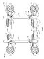
- FIG. 1is a perspective view of an embodiment of a dynamic spine stabilization system of the invention.
- FIG. 1Ais a posterior view of the embodiment of FIG. 1 implanted in a spine.
- FIG. 2is a top view of the embodiment of FIG. 1 .
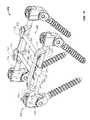
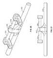
- FIG. 3is a perspective view of an embodiment of a horizontal rod system of the invention for use with a dynamic spine stabilization system such as depicted in FIG. 1 .
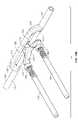
- FIG. 4is a perspective view of an alternative embodiment of a horizontal rod system of the invention for use with a dynamic spine stabilization system such as depicted in FIG. 1 .
- FIG. 5is a perspective view of an embodiment of an anchor system of the invention for use with a dynamic spine stabilization system such as depicted in FIG. 1 .
- FIG. 6is a another perspective view of the embodiment of the anchor system of FIG. 5 .
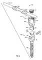
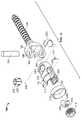
- FIG. 7is an exploded perspective view of an alternative embodiment of the anchor system of the invention for use with a dynamic spine stabilization system such as depicted in FIG. 1 .
- FIG. 8is a sectioned view of a portion of embodiment of the alternative anchor system of FIG. 7 of the invention.
- FIG. 9is a side view of the anchor system of FIG. 7 depicting a degree of freedom of movement of the anchor system of FIG. 7 .
- FIG. 9Ais an end view of the anchor system of FIG. 9 .
- FIG. 10is a side view of the anchor system of FIG. 7 depicting another degree of freedom of movement of the anchor system of FIG. 7 .
- FIG. 10Ais an end view of the anchor system of FIG. 10 .
- FIG. 11is a side view of the anchor system of FIG. 7 depicting yet another degree of freedom of movement of the anchor system of FIG. 7 .
- FIG. 11Ais an end view of the anchor system of FIG. 11 .
- FIG. 12is a perspective view of yet another embodiment of the anchor system of the invention.
- FIG. 13is an exploded perspective view of the embodiment of the anchor system of the invention of FIG. 12 .
- FIG. 14is a perspective view of yet another embodiment of the anchor system of the invention.
- FIG. 15is an exploded perspective view of the embodiment of the anchor system of the invention of FIG. 14 .
- FIG. 16is another exploded perspective view of the embodiment of the anchor system of the invention of FIG. 14 .
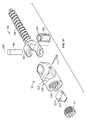
- FIG. 17is an exploded perspective view of another embodiment of the anchor system of the invention.
- FIG. 18is a perspective view of yet another embodiment of the anchor system of the invention.
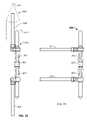
- FIG. 19is a perspective view of another embodiment of a dynamic spine stabilization system of the invention with another horizontal rod system.
- FIG. 19Ais a perspective view of another horizontal rod system of the invention as depicted in FIG. 19 and partially shown in phantom form.
- FIG. 19Bis an exploded perspective view of the embodiment of FIG. 19 .
- FIG. 19Cis a side view of the embodiment of FIG. 19 .
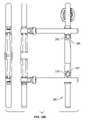
- FIG. 20is a top view of the another embodiment of the dynamic spine stabilization of the system of the invention of FIG. 19 .
- FIG. 20Ais a top side of the embodiment depicted in FIG. 19A .
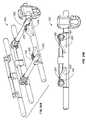
- FIG. 21is another perspective view of the embodiment of the dynamic spine stabilization of the invention of FIG. 19 .
- FIG. 22is a side view the embodiment of the horizontal rod system of the invention as depicted in FIG. 19 configured in a closed position for implantation.
- FIG. 22Ais an end view of the embodiment depicted in FIG. 22 .
- FIG. 23is a side view partially in phantom form of the horizontal rod system of FIG. 22 .
- FIG. 24is a side view of the embodiment of FIG. 22 in an open position as used when the embodiment is deployed in a spine.
- FIG. 25is an end view of the embodiment depicted in FIG. 24 .
- FIG. 26is a perspective view of yet another embodiment of the horizontal rod system of the invention.
- FIG. 27is a side view of the embodiment of the horizontal rod system of the invention of FIG. 26 .
- FIG. 28is a perspective view of still another embodiment of the horizontal rod system of the invention.
- FIG. 29is a side view of the embodiment of the horizontal rod system of the invention of FIG. 28 .
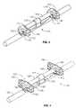
- FIG. 30is a top view of another embodiment of the horizontal rod system of the invention as depicted in FIG. 1 with the horizontal rod system in an undeployed position ready for implantation.
- FIG. 31is a top view of the embodiment of the horizontal rod system of FIG. 30 in a deployed position after implantation.
- FIG. 32is a side view, partially in phantom of the embodiment depicted in FIG. 30 .
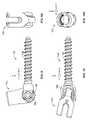
- FIG. 33is a side view of an alternative embodiment of the horizontal rod system of the invention.
- FIG. 33Ais a side view of yet another embodiment of the horizontal rod system of the invention.
- FIG. 34is a side view of another alternative embodiment of the horizontal rod system of the invention.
- FIG. 34Ais a perspective view of yet another embodiment of the horizontal rod system of the invention.
- FIG. 34Bis a side view of the embodiment of FIG. 34A .
- FIG. 34Cis a top view of the embodiment of FIG. 34A .
- FIG. 35is a side view of still another alternative embodiment of the horizontal rod system of the invention.
- FIG. 36is a side view of yet another alternative embodiment of the horizontal rod system of the invention.
- FIG. 37is a side view of another alternative embodiment of the horizontal rod system of the invention.
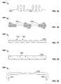
- FIG. 38is a side view of another alternative embodiment of the horizontal rod system of the invention.
- FIG. 39is a side view of yet another alternative embodiment of the horizontal rod system of the invention.
- FIG. 39Ais still another embodiment of the horizontal rod system and the anchor system of the invention.
- FIG. 39Bis yet another embodiment of the horizontal rod system and the anchor system of the invention.
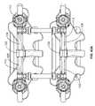
- FIG. 40is a perspective view of another embodiment of a dynamic spine stabilization system of the invention.
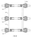
- FIG. 41is a perspective view of still another embodiment of a dynamic spine stabilization system of the invention.
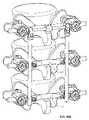
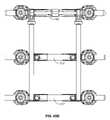
- FIG. 42is a side view of an embodiment of a two level dynamic spine stabilization system of the invention.
- FIG. 43is a side view of yet another embodiment of a two level dynamic spine stabilization system of the invention.
- FIG. 43Ais a side view of an alternative embodiment of a dynamic spine stabilization system of the invention.
- FIG. 44is a side view of an embodiment of a fusion system of the invention.
- FIG. 45is a side view of an embodiment of a two level fusion system of the invention.
- FIGS. 45A , 45 Bare perspective and side views of still another fusion system of an embodiment of the invention that has a transition level.
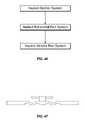
- FIG. 46is a flow chart of an embodiment of the method of the invention.
- FIG. 47is yet another embodiment of the horizontal rod system of the invention.
- Embodiments of the present inventioninclude a system or implant and method that can dynamically stabilize the spine while providing for preservation of spinal motion.
- Alternative embodimentscan be used for spine fusion.
- Embodiments of the inventioninclude a construct with an anchoring system, a horizontal rod system that is associated with the anchoring system and a vertical rod system that is associated with the anchoring system and the horizontal rod system.
- the anchoring systemincludes a head or saddle that allows for appropriate, efficient and convenient placement of the anchoring system relative to the spine in order to reduce the force that is placed on the anchoring system.
- the anchor systemhas enhanced degrees of freedom which contribute to the ease of implantation of the anchor system. Accordingly, the anchor system is designed to isolate the head and the screw from the rest of the dynamic stabilization system and the forces that the rest of the dynamic stabilization system can place on the anchor system and the anchor system/bone interface. Thus, the anchor system can provide a secure purchase in the spine.
- the horizontal rod systemis in part comprised of a super elastic material that allows for convenient positioning of the horizontal rod system relative to the anchor system and allows for isolation of the horizontal rod system from the anchor system so that less force is placed on the anchor system from the horizontal rod system and on the anchor system/bone interface. Accordingly, unlike prior devices the anchor system stays secure in the bone of the spine.
- An aspect and advantage of the inventionis the ability to maximize the range of motion of the spine after embodiments of the dynamic stabilization, motion preservation implant of the invention are implanted in a patient. While traditional solutions to back pain include fusion, discectomy, and artificial implants that replace spine structure, embodiments of the present invention preserve the bone and ligament structure of the spine and preserve a wide range of motion of the spine, while stabilizing spines that were heretofore unstable due to degenerative and other spinal diseases.
- Still another aspect of the inventionis the preservation of the natural motion of the spine and the maintenance of the quality of motion as well as the wide range of motion so that the spine motion is as close to that of the natural spine as possible.
- the present embodiments of the inventionallow for the selection of a less stiff, yet dynamically stable implant for use in a non-fusion situation.
- a less stiff, yet dynamically stable implantrelates directly to a positive patient outcome, including patient comfort and the quality of motion of the spine.
- load sharingis provided by the embodiment, and, in particular, the deflection rod or loading rod of the embodiment.
- the terms “deflection rod” and “loading rod”can be used interchangeably.
- this aspect of the inventionis directed to restoring the normal motion of the spine.
- the embodimentprovides stiffness and support where needed to support the loads exerted on the spine during normal spine motion, which loads, the soft tissues of the spine are no longer able to accommodate since these spine tissues are either degenerated or damaged.
- Load sharingis enhanced by the ability to select the appropriate stiffness of the deflection rod or loading rod in order to match the load sharing desired.
- the stiffness of the implant of the systemcan be selected among a number of loading rods. In other words, the stiffness is variable depending on the deflection rod or loading rod selected.
- the load sharingis between the spine and the embodiment of the invention.
- the deflection rod or loading rodis cantilevered. In another aspect the deflection rod or loading rod is cantilevered from a horizontal rod. In yet another aspect the deflection rod or loading rod is cantilevered from a horizontal rod that is connected between two anchors that are affixed to the same vertebra. In yet another aspect the deflection rod or loading rod is about parallel to the horizontal rod in a resting position. In still a further, aspect the deflection rod or loading rod is cantilevered from a mount on the horizontal rod and said deflection rod or loading rod is about parallel to the horizontal rod in a resting position.
- the horizontal rod attached directly to opposite anchorsis stiff and rigid, and the cantilevered deflection rod or cantilevered loading rod shares the load with the spine resulting from the motions of the body of the patient.
- the load being absorbed or carried by the embodimentis being distributed along at least part of the length of the deflection rod or loading rod. In another aspect of the invention, the load being absorbed or carried by the embodiment is distributed along at least part of the length of the horizontal cantilevered deflection rod or horizontal cantilevered loading rod.
- the embodiments of the inventioncan be made smaller in order to fit in more spaces relative to the spine.
- the embodimentscan fit in the L5-S1 space of the spine.
- An aspect of the inventionis to preserve and not restrict motion between the pedicles of the spine through the use of appropriately selected horizontal and vertical rods of embodiments of the invention.
- An aspect of the inventionis to provide for load bearing on horizontal elements such as horizontal rods instead of vertical elements or rods, and, in particular, vertical elements that are connected between bone anchoring systems.
- An aspect of the inventionis the use of horizontal rods in the embodiments of the invention in order to isolate each level of the implantation system from the other so as not to put undue force and/or torque on anchoring systems of embodiment of the invention and associated bone, and so as to allow customization of the implantation system to the need of the patient. Accordingly, an aspect of the invention is to provide for minimized loading on the bone/implantation system interface. Customization, in preferred embodiments, can be achieved by the selection of the horizontal rod with the desired stiffness and stiffness characteristics. Different materials and different implant configurations enable the selection of various stiffness characteristics.
- Another aspect of the inventionis the ability to control stiffness for extension, flexion, lateral bending and axial rotation, and to control stiffness for each of these motions independently of the other motions.
- An aspect of the inventionis to use the stiffness and load bearing characteristics of super elastic materials.
- Another aspect of the inventionis to use super elastic materials to customize the implant to the motion preservation and the dynamic stabilization needs of a patient.
- An aspect of such embodiments of the inventionis to provide for a force plateau where motion of the implantation system continues without placement of additional force of the bone anchor system, or, in other words, the bone/implantation system interface.
- an aspect of the inventionis to use the horizontal bar to offset loading on the anchor system and on the implantation system in general.
- an aspect of the inventionis to be able to selectively vary the stiffness and selectively vary the orientation and direction that the stiffness is felt by varying the structure of the implantation system of the invention, and, in particular, to vary the stiffness of the horizontal rod system of the invention.
- Another aspect of embodiments of the inventionis to prevent any off-axis implantation by allowing the implantation system to have enhanced degrees of freedom of placement of the implant.
- Embodiments of the inventionprovide for off-axis placement of bone anchor or pedicle screw systems.
- a further aspect of embodiments of the inventionis to control stabilized motion from micro-motion to broad extension, flexion, axial rotation, and lateral bending motions of the spine.
- Yet another aspect of the embodiments of the inventionis to be able to revise a dynamic stabilization implant should a fusion implant be indicated. This procedure can be accomplished by, for example, the removal of the horizontal rods of the implantation system and replacement of such rods with stiffer rods. Accordingly, an aspect of the invention is to provide for a convenient path for a revision of the original implantation system, if needed.
- a further aspect of the inventiondue to the ease of implanting the anchoring system and the ease of affixing vertical rods to the horizontal rods of the invention, is the ability to accommodate the bone structure of the spine, even if adjacent vertebra are misaligned with respect to each other.
- a further aspect of the inventionis that the implant is constructed around features of the spine such as the spinous processes and, thus, such features do not need to be removed and the implant does not get in the way of the normal motion of the spine features and the spine features do not get in the way of the operation of the implant.
- Another aspect of embodiments of the inventionis the ability to stabilize two, three and/or more levels of the spine by the selection of appropriate embodiments and components of embodiments of the invention for implantation in a patient. Further embodiments of the invention allow for fused levels (in conjunction with, if desired, bone graphs) to be placed next to dynamically stabilized levels with the same implantation system. Such embodiments of the invention enable vertebral levels adjacent to fusion levels to be shielded by avoiding an abrupt change from a rigid fusion level to a dynamically stable, motion preserved, and more mobile level.
- another aspect of the embodiments of the inventionis to provide a modular system that can be customized to the needs of the patient.
- Horizontal rodscan be selectively chosen for the particular patient as well the particular levels of the vertebrae of the spine that are treated. Further, the positioning of the various selected horizontal rods can be selected to control stiffness and stability.
- embodiments of the inventioncan be constructed to provide for higher stiffness and fusion at one level while allowing for lower stiffness and dynamic stabilization at another adjacent level.
- Yet a further aspect of the inventionis to provide for dynamic stabilization and motion preservation while preserving the bone and tissues of the spine in order to lessen trauma to the patient and to use the existing functional bone and tissue of the patient as optimally as possible in cooperation with embodiments of the invention.
- Another object of the inventionis to implant the embodiments of the invention in order to unload force from the spinal facets and other posterior spinal structures and also the intervertebral disk.
- a further aspect of the inventionis to implant the embodiment of the invention with a procedure that does not remove or alter bone or tear or sever tissue.
- the muscle and other tissuecan be urged out of the way during the inventive implantation procedure.
- an aspect of the inventionis to provide for a novel implantation procedure that is minimally invasive.
- a dynamic stabilization, motion preservation system 100 embodiment of the inventionis depicted in FIG. 1 and includes an anchor system 102 , a horizontal rod system 104 , and a vertical rod system 106 .
- horizontalrefers to a horizontal orientation with respect to a human patient that is standing
- verticalrefers to a vertical orientation with respect to a patient that is standing ( FIG. 1A ).
- the anchor system 102includes a bone screw 108 which is mounted to a head or saddle 110 .
- the bone screw 108can be replaced by a bone hook as more fully described in U.S. Provisional Patent Application No.
- the head or saddle 110to the bone screw 108 allows for multiple degrees of freedom in order that the bone screw 108 may be appropriately, conveniently, and easily placed in the bone of the spine and in order to assist in isolating the bone screw 108 from the remainder of the system 100 so that less force is placed on the anchor system 102 and on the bone screw/bone interface.
- Some prior art devices, which use such bone screwshave, on occasion, had the bone screws loosen from the spine, and the present embodiment is designed to reduce the force on the bone screw and on the bone screw/bone interface.
- the anchor system 102is comprised of titanium.
- other biocompatible materialssuch as stainless steal and/or PEEK can be used.
- the horizontal bar system 104is preferably secured through the head 110 of the anchor system 102 with a locking set screw 112 .
- This embodimentincludes a first horizontal rod 114 and a second horizontal rod 116 .
- the first horizontal rod 114has first and second deflection rods or loading rods 118 and 120 secured thereto.
- the first horizontal rodcan be comprised of titanium, stainless steel or PEEK or another biocompatible material, and the first and second deflection rods or loading rods can be comprised of a super elastic material.
- the super elastic materialis comprised on Nitinol (NiTi).
- Nitinol or nickel-titaniumNiTi
- other super elastic materialsinclude copper-zinc-aluminum and copper-aluminum-nickel.
- the nickel-titaniumis the preferred material.
- the deflection rods or loading rods 118 and 120are mounted in the center of the first horizontal rod 114 to a mount 122 .
- the deflection rods or loading rods 118 and 120are force fit into the mount 122 .
- the deflection rods or loading rodsmay be screwed, glued, or laser welded to the mount 122 and to bores placed in the mount 122 .
- the first horizontal rod 114includes first and second ridges 124 , 126 located on either side of the mount 122 and extend at least partially along the length of the first horizontal rod 114 toward the respective ends of the horizontal rod 114 .
- These ridges 124 , 126add rigidity to the mount 122 relative to the rest of the horizontal rod system 104 .
- the deflection rods or loading rods 118 , 120have a constant diameter extending outwardly toward the respective ends 128 , 130 of the deflection rods or loading rods 118 , 120 .
- the deflection rods or loading rods 118 , 120can have a varying diameter as the rods 118 , 120 approach their respective ends 128 , 130 .
- the rods 118 and 120can have a decreasing diameter as the rods approach the respective ends 128 , 130 .
- the decreasing diameterallows the super elastic rods 118 , 120 to be more flexible and bendable along the length of the rods as the rods approach the ends 128 , 130 and to more evenly distribute the load placed on the system 100 by the spine.
- the diameter of the deflection rods or loading rodscontinuously decreases in diameter.
- the diametercan decrease in discrete steps along the length, with the diameter of one step not being continuous with the diameter of the next adjacent step.
- the diameters of the deflection rods or loading rodscan continuously increase in diameter or can have discreet step increases in diameter along the length of the deflection rods or loading rods as the rods extent toward the respective ends 128 , 130 .
- the rodscan have at least one step of decreasing diameter and at least one step of increasing diameter in any order along the length of the deflection rods or loading rods as the rods approach the respective ends 128 , 130 , as desired for the force and load carrying characteristics of the deflection rods or loading rods 118 , 120 .
- the horizontal rod system 104and, in particular, the deflection rods 118 , 120 , share the load carried by the spine.
- This load sharingis directed to restoring the normal motion of the spine.
- This embodiment, and, in particular, the deflection rods or loading rods 118 , 120provide stiffness and support where needed to support the loads exerted on the spine during spine motion, which loads, the soft tissues of the spine are no longer able to accommodate since these spine tissues are either degenerated or damaged.
- Such load sharingis enhanced by the ability to select the appropriate stiffness of the deflection rods or loading rods 118 , 120 in order to match the load sharing desired.
- the stiffness of the deflection or loading rodscan be selected from a number of deflection or loading rods. The stiffness is variable depending on the deflection or load rod selected. As indicated herein, the stiffness of the deflection or loading rod can be varied by the shape of the rod and the selection of the material. Shape variations can include diameter, taper, direction of taper, stepped tapering, and material variation can include composition of material, just to name a few variations.
- the load carried by the deflection or loading rodsis distributed along at least part of the length of the deflection or loading rods. Preferably, the load is distributed along the entire length of the deflection or loading rods.
- the embodiments of the inventioncan be made smaller in order to fit in more spaces relative to the spine.
- embodimentscan fit, for example, in the L5-S1 space of the spine in addition to generally less constrained spaces such as the L4-L5 space of the spine.
- the deflection rods or loading rods 118 , 120are cantilevered from mount 122 .
- these deflection rods 118 , 120have a free end and an end fixed by the mount 112 , which mount is located on the horizontal rod 114 .
- the cantilevered deflection rods 118 , 120are about parallel in a rested position to the horizontal rod 114 , and, in this embodiment, the horizontal rod is directly connected to the anchor systems and, in particular, to the heads or saddles of the anchor system.
- the horizontal rod 114is stiff and rigid and, particularly, in comparison to the deflection rods. In this arrangement, the horizontal rod system and, in particular, the deflection rods 118 , 120 share the load resulting from the motions of the body of the patient.
- the second horizontal rod 116could be replaced with a horizontal rod 114 which has deflection rods or loading rods ( FIG. 43A ).
- both horizontal rodswould have deflection rods or loading rods.
- the deflection rods or loading rods mounted on one horizontal rodwould be connected to vertical rods and the vertical rods would be connected to deflection rods or loading rods mounted on the other horizontal rod.
- Such an embodimentprovides for more flexibility.
- the deflection rods or loading rods 118 , 120can have other configurations and be within the spirit and scope of the invention.
- the vertical rod systemis comprised of, in this embodiment, first and second vertical rods 132 , 134 which are secured to first and second connectors 136 , 138 located at the ends 128 , 130 of the first and second deflection rods or loading rods 118 , 120 .
- the vertical rods 132 , 134are preferably connected in such a way as to be pivotal for purposes of implantation in a patient and for purposes of adding flexibility and dynamic stability to the system as a whole.
- These vertical rods 132 , 134are preferably made of titanium. However, other bio-compatible materials can be used.
- the vertical rods 132 , 134are also connected to the second horizontal rod 116 by being received in C-shaped mounts 140 , 142 located on the second horizontal rods and in this embodiment, held in place by set screws 144 , 146 . It is to be understood by one of ordinary skill in the art that other structures can be used to connect the vertical rods to the horizontal rods.
- the vertical rodsare only connected to the horizontal rods and not to the anchoring system 102 in order to isolate the anchor system 102 and, in particular, the heads 110 from stress and forces that could be placed on the heads, and from forces transferred to the heads where the vertical rods connect to the heads.
- the system 100 through the vertical and horizontal rodsallow for dynamic stability, and a wide range of motion without causing undue force to be placed on the heads of the anchor systems.
- These embodimentsalso allow for each level of the spine to move as freely as possible without being unduly restrictively tied to another level.
- More lateral placement of the vertical rods toward the heads of the anchor systemprovides for more stiffness in lateral bending and an easier implant approach by, for example, a Wiltse approach as described in “The Paraspinal Sacraspinalis-Splitting Approach to the Lumber Spine,” by Leon L. Wiltse et al., The Journal of Bone & Joint Surgery , Vol. 50-A, No. 5, July 1968, which is incorporated herein by reference.
- the stiffness of the system 100can preferably be adjusted by the selection of the materials and placement and diameters of the horizontal and vertical rods and also the deflection rods or loading rods. Larger diameter rods would increase the resistance of the system 100 to flexion, extension rotation, and bending of the spine, while smaller diameter rods would decrease the resistance of the system 100 to flexion, extension, rotation and bending of the spine. Further, continually or discretely changing the diameter of the rods such as the deflection rods or loading rods along the length of the rods changes the stiffness characteristics. Thus, with the deflection rods or loading rods 118 , 120 tapered from the mount 122 toward the ends 128 , 130 , the system can have more flexibility in flexion and extension of the spine.
- the horizontal rods and the vertical rodsin addition to the horizontal deflection rods or loading rods adds to the flexibility of the system 100 .
- all of the horizontal and vertical rods, in addition to the deflection rods or loading rods,can be made of titanium or stainless steel or PEEK should a stiffer system 100 be required.
- the system 100can easily accommodate the desired stiffness for the patient depending on the materials uses, and the diameter of the materials, and the placement of the elements of the system 100 .
- an implanted system 100need to be revised, that can be accomplished by removing and replacing the horizontal and/or vertical rods to obtain the desired stiffness.
- the horizontal rods having the deflection rods or loading rodscan be removed and replaced by horizontal rods having deflection rods or loading rods made of titanium, or stainless steel, or non-super elastic rods to increase the stiffness of the system. This can be accomplished by leaving the anchor system 102 in place and removing the existing horizontal rods from the heads 110 and replacing the horizontal rods with stiffer horizontal rods and associated vertical rods.
- FIG. 3depicts a view of the horizontal rod 104 as previously described.
- the connectors 136 , 138are shown on the ends of the deflection rods or loading rods 118 , 120 .
- the connectorscan be forced-fitted to the deflection rods or fastened in other methods known in the art for this material and as further disclosed below.
- the connectors 136 , 138have slits 148 , 150 to aid in placing the connectors onto the ends of the deflection rods.
- the connectors 136 , 138each include upper and lower arms 160 , 162 which can capture there between the vertical rods 132 , 134 .
- the armseach include an aperture 168 , 170 that can accept a pin or screw 176 , 178 ( FIG. 1 ) for either fixedly or pivotally securing the vertical rods 132 , 134 .
- the vertical rodsinclude a head 162 , 164 that can be force fit or screwed onto the rest of the vertical rods.
- the headsinclude apertures 172 , 174 for accepting the pins or screws 176 , 178 .
- the system 100has as low a profile as possible and extends from the spine as little as possible, it is advantageous to place the deflection rods or loading rods 118 , 120 as close to the first horizontal rod 114 as possible.
- preferably notches 152 , 154are placed in horizontal rod 114 to accommodate the connectors 136 , 138 .
- the purpose for the notchesis to provide for a horizontal rod with a low profile when implanted relative to the bones and tissues of the spine so that there is, for example, clearance for implant and the motion of the implant, and to keep the deflection rods or loading rods as close as possible to the horizontal rods in order to reduce any potential moment arm relative to the mounts on the horizontal rod.
- FIG. 4depicts another embodiment of the horizontal rod 114 with deflection rods or loading rods 118 , 120 and with difference connectors 156 , 158 .
- Connectors 156 , 158each include two pairs of upper and lower arms 160 , 162 extending in opposite directions in order for each connector 156 , 158 to mount an upper and a lower vertical rod as presented with respect to FIG. 46 . This configuration allows for a three level system as will be described below.
- FIG. 5A preferred embodiment of the anchor system 102 invention can be seen in FIG. 5 .
- This anchor system 102includes a bone screw 108 with a head 110 in the form of a U-shaped yoke 180 with arms 182 , 184 .
- a hookpreferably with bone engaging barbs or projections, can be substituted for the bone screw 108 .
- the hook embodimentis further described in the above referenced and incorporated provisional application. The hooks are used to hook to the bone, such as the vertebra instead of having screws anchored into the bone.
- Each of the arms 182 , 814 of yoke 180includes an aperture 186 , 188 through which a pin 190 can be placed.
- the pin 190can be laser welded or force fit or glued into the yoke 180 , as desired.
- the pin 190can be smooth or roughened as discussed below.
- the pin 190can be cylindrical or be comprised of a multiple sides as shown in FIG. 7 . In FIG. 7 , pin 190 has six sides and one or more of the accommodating apertures 186 , 188 can also include mating sides in order to fix the position of the pin 190 in the yoke 180 .
- a compression sphere 200is placed over the pin 190 .
- the compression sphere 200can have a roughened surface if desired to assist in locking the sphere in place as described below.
- the compression sphere 200can include one or more slits 202 to assist in compressing the sphere 200 about the pin 190 .
- the compression sphere 200can have an inner bore that is cylindrical or with multiple sides in order conform to and be received over the pin 190 .
- one or more spacer rings 204can be used to space the compression ring from the yoke 180 in order to assist in providing the range of motion and degrees of freedom that are advantageous to the embodiments of the invention.
- Head 110 in FIGS. 7 , 8is somewhat different from head 110 in FIG. 1 as will be described below.
- Head 110 in FIGS. 7 , 8includes a cylindrical body 206 with a lower end having an aperture 208 that can receive the compression sphere 200 .
- the aperture 208can have a concave surface as depicted in FIGS. 7 , 8 . Accordingly, the compression sphere 200 fits inside of the concave surface of aperture 208 and is free to move therein until restrained as described below.
- the lower end of the cylindrical body 206 about the aperture 208has some of the material that comprised wall 224 removed in order to accommodate the motion of the yoke 180 of the bone screw 108 .
- the portion of the wall 224 adjacent to the arms 182 , 184 of the yoke 180has been removed to accommodate the yoke 180 and the range of motion of the yoke.
- the head 110 of the anchor system 102includes an internal cylindrical bore 210 which is preferably substantially parallel to a longitudinal axis of the head 110 .
- This bore 210is open to the aperture 208 and is open and preferably substantially perpendicular to the distal end 212 of the head 110 .
- the bore 210is threaded and can accept the set screw 112 .
- aligned U-shaped slotsthat extend through the head 110 from the outer surface to the bore 210 . These U-shaped slots are also open to the distal end 212 of the head 110 in order to have the set screw 112 accepted by the threads of the bore 210 .
- a compressor element or cradle 220Located in the bore 210 between the set screw 112 and the compression sphere 200 is a compressor element or cradle 220 .
- the compressor element or cradle 220can slide somewhat in the bore 210 , but the compressor element or cradle 220 is restrained by a pin 222 ( FIG. 7 ) received through the wall 224 of the head 110 and into the compressor element or cradle 220 .
- a pin 222FIG. 7
- the compressor element or cradle 220has a generally cylindrical body so that the compressor element 220 can fit into bore 210 .
- An upper end 226 of the compressor element 220includes a concave surface 228 .
- This surface 228is shaped to fit the horizontal rod system 104 and, in particular, a horizontal rod 114 , 116 .
- the lower end of the compressor element 220includes a concave surface 230 which can accommodate the compression sphere 200 .
- the lower end of the compressor element 220 adjacent to the concave surface 230has an additional concave surface 232 ( FIG. 8 ) which is used to accommodate the motion of the upper end of the yoke 180 as the head 110 is moved relative to the bone screw 108 .
- the concave surfaces 228 and 230can be roughened, if desired, to assist in locking the head 110 relative to the bone screw 108 .
- there is no top compression element or cradlein order to reduce the profile of the head of the anchor system.
- the set screwcan press against the horizontal rod 114 , 116 , which horizontal rod 114 , 116 , can press against the compressor element or cradle 220 , which compressor element or cradle 220 can press against the compression sphere 220 , which compression sphere can press against the pin 190 in order to lock the horizontal rod 114 , 116 relative to the head 110 and to lock the head 110 relative to the bone screw 108 .
- all of the surfaces that are in contactcan be roughened to enable this locking, if desired.
- the surfacesmay be smooth with the force of the set screw 112 urging of the elements together and the resultant locking
- This alternative horizontal rod 114 , 116includes first and second concave openings 234 , 236 which can receive vertical rods such as vertical rods 132 , 134 ( FIG. 1 ).
- the horizontal rod 114 , 116is substantially cylindrical with the areas around the concave openings 234 , 236 bulked up or reinforced as desired to support the forces. Additionally, threaded bores are provided adjacent to the concave openings 234 , 236 and these bores can receive screws that have heads that can be used to lock vertical rods in place.
- the screwscan retain short bars that project over the concave openings 234 , 236 in order to hold the vertical rods in place ( FIG. 34 ).
- the short retaining barscan also have concave openings that conform to the shape of, and receive at least part of, the vertical rods in order to retain the vertical rods in place with the system 100 implanted in a patient.
- the head 110 depictedis a preferred embodiment and is somewhat different from the head 110 as seen in FIG. 8 .
- the head body 206 , the outer surface 218 of the head and the head wall 224have been configured in order to prevent splaying of the head 110 when the set screw 112 locks the anchor system 102 as explained above.
- the head 110 and, in particular, the wall 224is reinforced about the U-shaped slot 216 that received the horizontal bar system 104 .
- the head 110can use a number of shapes to be reinforced in order to prevent splaying.
- the exemplary embodiment of FIGS. 1 , 2includes a pitched roof shape as seen in the top view looking down on distal end 212 of the head 110 .
- the wall about the U-shaped slot 216is thickened, while the portion of the head distal from the U-shaped slot can be less thick if desired in order to reduce the bulk and size of the head 110 and, thus, give the head 110 a smaller profile relative to the bone and tissue structures when implanted in a patient.
- the small profileallows greater freedom of motion of the system 100 as described below.
- the head 110can be shorter and, thus, stand less prominently out of the bone when the bone screw 108 in implanted in a spine of a patient for example.
- the anchor system 102includes a number of degrees of freedom of motion. These degrees of freedom of motion are depicted in FIGS. 9 , 9 A, 10 , 10 A, and 11 , 11 A.
- FIG. 9establishes a frame of reference including a longitudinal axis x which is along the longitudinal length of the bone screw 108 , a y axis that extends perpendicular to the x axis, and a lateral axis z which is perpendicular to both the x axis and the y axis and extends outwardly from and parallel to the pin 190 of the yoke 180 of the anchor system 102 .
- FIGS. 9establishes a frame of reference including a longitudinal axis x which is along the longitudinal length of the bone screw 108 , a y axis that extends perpendicular to the x axis, and a lateral axis z which is perpendicular to both the x axis and the y axis and extends outwardly from and parallel to the pin 190 of the yoke 180 of the anchor system 102 .
- the system 100due to the embodiments as disclosed herein is able to have the head 110 rotate about the z axis from about 80 degrees to about zero degrees and, thus, in line with the x axis and from the zero degree position to about 80 degrees on the other side of the x axis. Accordingly, the head is able to rotate about 160 degrees about the z axis relative to the bone screw 108 . As seen in FIGS. 10 , 10 A the head 110 is able to tilt about 0.08 inches (2 mm) relative to and on both sides of the x axis.
- the head 110can tilt from about 12 degrees to zero degrees where the head 110 is about parallel to the x axis and from zero degrees to 12 degrees about the y axis and on the other side of the x axis.
- the headcan tilt through about 24 degrees about the y axis.
- the head 110can swivel for a total of about 40 degrees about the x axis.
- the head 110can swivel about the x axis from about 20 degrees to one side of the z axis to zero degrees and from zero degrees to about 20 degrees on the other side of the z axis.
- the headis able to substantially exercise all of these degrees of freedom at once and, thus, can have a compound position relative to the bone screw by simultaneously moving the head within the ranges of about 160 degrees about the z axis ( FIG. 9 ), about 24 degrees from the y axis ( FIG. 10 ) and about 40 degrees about the x axis ( FIG. 11A ).
- the range of motion in the axial planeis about 180 degrees or about 90 degrees on each side of the centerline.
- the range of motion in the Caudal/Cephalad orientationis about 4 mm or about 2 mm on each side of the centerline or about 24 degrees or about 12 degrees on each side of the centerline.
- the range of motion in the coronal planeis about 40 degrees or about 20 degrees on each side of the centerline.
- FIGS. 12 , 13depict yet another embodiment of the anchor system 102 of the invention where elements that are similar to elements of other embodiments and have similar reference numbers.
- this embodimentincludes a lower cradle or compressor element 220 that is similar to the cradle or compressor element 220 of the embodiment of FIG. 7 with the head 110 similar to the head 110 as seen in FIG. 7 .
- the compression sphere 200is similar to the compression sphere 200 in FIG. 7 with the compression sphere including a plurality of slits provided about the axis of rotation 238 of the sphere 200 .
- the slits 202have openings that alternate between facing the north pole of the axis of rotation of the sphere 200 and facing the south pole of the axis of rotation of the sphere 200 .
- the slitscan be provided in the sphere and have no opening relative to the north or south pole of the axis of rotation of the sphere 200 . Still further, the slits can open relative to only one of the north or south poles.
- FIGS. 12 , 13there is also an upper cradle or compressor element 240 which is positioned adjacent to the set screw 214 (see also FIG. 7 ).
- the upper cradle or compressor element 240has a generally cylindrical body which can slide in the cylindrical bore of the head 110 with an upper end having fingers 242 extending therefrom.
- the fingers 242can spring over a bore formed in the lower surface of the set screw 214 in order to retain the cradle 240 relative to the set screw 214 and to allow the cradle 240 to rotate relative to the set screw 214 .
- the lower surface of the cradle 240includes a concave surface 244 which can mate with a horizontal rod 114 , 116 in order to lock the rod relative the head 110 and the head 110 relative to the bone screw 108 . If desired, the concave surface 244 can be roughened to assist in locking the system 100 .
- a retaining ring 246is depicted.
- the retaining ringcan be force fit over the outer surface 218 of the head 110 , or pop over and snap under a ridge 248 at the distal end 212 of the head 110 , or can have internal threads that mate with external threads located on the outer surface of the 218 of the head 110 .
- the head side wall 224includes a lateral or side opening 250 which communicates with the cylindrical bore 210 which is located in head 110 .
- the lateral or side openingpreferably extends more than 180 degrees about the outer surface of the head.
- the side opening 250includes a lip 252 and the side opening extends down below the lip into communication with the cylindrical bore 210 and follows the outline of the concave surface 228 of the cradle 220 .
- a horizontal rod 114 , 116can be positioned through the side opening 250 and urged downwardly into contact with the concave surface 228 of the cradle 220 .
- the cradle 220includes a downward projecting post 254 .
- this embodimentdoes not include a compression sphere, and instead the pin 190 , which can have a larger diameter than a pin 190 in other embodiments, comes in direct contact with the post 254 when the set screw 112 locks the anchor system 100 .
- the pin 190can have a roughened surface 256 to assist in the locking of the anchor system 100 . As is evident from FIGS.
- this embodimenthas a side loading head 110 , the distal end of the head is a fully cylindrical without communicating with any lateral U-shaped slots of the other embodiments. Accordingly, this embodiment does not include any retaining ring or reinforced areas that can be used to prevent splaying.
- FIG. 17depicts yet another embodiment of the anchor system 102 that has a lateral or side loading head 110 .
- a compression cylinder 258is placed over the pin 190 .
- the compression cylinder 258can slide along the longitudinal axis 260 of the pin 190 , if desired.
- the head 110can rotate about the pin 190 and the compression cylinder 258 .
- the head 110can also slide or translate along the longitudinal axis 260 of the pin as well as the longitudinal axis of the compression cylinder 258 .
- Compression cylinder 258has slits 262 that can be configured similarly as the slits 202 of the other embodiments of the anchor system 100 described and depicted herein.
- FIG. 18depicts still another embodiment of the anchor system 100 that has a lateral or side loading head 110 .
- This embodimentincludes a compression sphere 200 provided over a pin 190 which is similar to the other compression spheres 200 depicted and described herein. Accordingly, this embodiment has the freedom of motion described with respect to the other embodiments which use a compression sphere.
- each embodiment of the anchor systemdoes not necessarily depict all the elements of another embodiment of the anchor system, that one of ordinary skill in the art would be able to use elements of one embodiment of the anchor system in another embodiment of the anchor system.
- Embodiments of the horizontal rod system 104 of the inventioninclude the embodiments describes above, in addition to the embodiments that follow.
- An aspect of the horizontal rod system 104is to isolate the anchor system 102 and reduce the stress and forces on the anchor system. This aspect is accomplished by not transmitting such stresses and forces placed on the horizontal rod system by, for example, flexion, extension, rotation or bending of the spine to the anchor system. This aspect thus maintains the integrity of the placement of the anchor system in, for example, the spine and prevents loosening of the bone screw or bone hook of the anchor system.
- various horizontal rod systemscan be used to control the rigidity, stiffness and/or springiness of the dynamic stabilization system 100 by the various elements that comprise the horizontal rod system.
- the horizontal rod systemcan be used to have one level of rigidity, stiffness and/or springiness in one direction and another level in a different direction.
- the horizontal rod systemcan offer one level of stiffness in flexion of the spine and a different level of stiffness in extension of the spine.
- the resistance to lateral bendingcan be controlled by the horizontal rod system. Select horizontal rod systems allow for more resistance to lateral bending with other select horizontal rod systems allow for less lateral bending.
- placement of the vertical rodsalso effects lateral bending. The more laterally the vertical rods are placed, the more stiff the embodiment is to lateral bending.
- the horizontal rod systemconnects to the heads of the anchor system without the vertical rod system connecting to the heads.
- two anchor systemsare secured to each vertebral level with a horizontal rod system connected between the two anchor systems. This further ensures that less stress and force is placed on the anchor systems secured to each level and also enables dynamic stability of the vertebra of the spine. Accordingly, movement of the vertebra relative to each other vertebra, as the spine extends, flexes, rotates and bends, is stabilized by the horizontal rods and the entire system 100 without placing excessive force or stress on the anchor system as there are no vertical rods that connect the anchor systems of one vertebra level with the anchor system of another vertebra.
- FIG. 19 through FIG. 25another embodiment of the horizontal rod system 304 of the dynamic stabilization system 300 is depicted as used with an anchor system 102 of the embodiment depicted in FIG. 1 .
- the horizontal rod system 304includes first and second horizontal rods 308 , 310 .
- FIG. 19Ashows a second image of only the horizontal rod 308 in a first undeployed position and that FIG. 19 shows a deployed position with the horizontal rod 308 connected with vertical rods 306 and, thus, the entire system 300 .
- the horizontal rod 308includes first and second aligned end rods 312 , 314 which are connected together with an offset rod 316 located between the first and second end rods 312 , 314 .
- the horizontal rod 308looks much like a yoke with the offset rod joining each of the end rods 312 , 314 with a curved section 318 , 320 .
- At the junction of the first end rod 312 and the offset rod 316is a first bore 322 which is aligned with the first end rod 312
- the second end rod 314 and the offset rod 316is a second bore 324 which is aligned with the second end rod 314 and, thus, aligned with the first end rod 312 .
- deflection rods or loading rods 324 , 328are made of a super elastic material such as, for example, Nitinol (NiTi) and the rest of system 300 is comprised of titanium, stainless steel, a biocompatible polymer such as PEEK or other biocompatible material.
- a super elastic materialsuch as, for example, Nitinol (NiTi) and the rest of system 300 is comprised of titanium, stainless steel, a biocompatible polymer such as PEEK or other biocompatible material.
- other super elastic materialsinclude copper-zinc-aluminum and copper-aluminum-nickel.
- the nickel-titaniumis the desired material.
- the super elastic materialhas been selected for the deflection rods as the stress or force/deflection chart for a super elastic material has a plateau where the force is relatively constant as the deflection increases.
- a super elastic rodhas a load (y) axis/deflection (x) axis curve which has a plateau at a certain level where the load plateaus or flattens out with increased deflection. In other words, the rod continues to deflect with the load staying constant at the plateau.
- the load plateauis about 250 Newtons to about 300 Newtons. It is to be understood that the plateau can be customized to the needs of the patient by the selection of the type and composition of the super elastic material.
- the plateaushould be lower, and, for others, the plateau should be higher. Accordingly, and, for example, at the plateau, additional force is not put on the anchor system 102 and, thus, additional force is not put on the area of implantation of the bone screw 108 and the surrounding bone of the spine where the bone screw 108 is implanted.
- the deflection rods or loading rods 326 , 328are force fit, screwed, welded, or glued into the bores 322 , 324 as desired.
- the first and second deflection rods or loading rods 326 , 328extend from the respective bores 322 , 324 toward each other and are joined by a Y-shaped connector 330 .
- the Y-shaped connector 330includes a base 332 which has opposed and aligned bores 334 , 336 that can receive the deflection rods or loading rods 326 , 328 in a manner that preferably allows the Y-shaped connector to pivot about the longitudinal axis defined by the aligned first and second deflection rods or loading rods 326 , 328 .
- the Y-shaped connector 330includes first and second arms that preferably end in threaded bores 342 , 344 that can receive the threaded ends of the vertical bar system 306 as described below.
- first and second armsthat preferably end in threaded bores 342 , 344 that can receive the threaded ends of the vertical bar system 306 as described below.
- recesses 346 , 348FIG. 24
- the horizontal rod 308can be more easily implanted between the tissues and bones of the spine and, in particular, guided between the spinous processes.
- the Y-shaped connector 330can be deployed by rotating it about 90 degrees or as required by the anatomy of the spine of the patient and connected with the vertical rod system 306 .
- the second horizontal rod 310is similar to the second horizontal rod 116 of the embodiment of FIG. 1 .
- This second horizontal rod 310is preferably comprised of titanium or other biocompatible material and includes first and second mounts 350 , 352 which can receive the ends of the vertical rod system 306 .
- the mounts 350 , 352include respective recesses 354 , 356 which can receive the vertical rods 358 , 360 of the vertical rod system 306 .
- the mounts 350 , 352also include tabs 362 , 364 which can capture the vertical rods 358 , 360 in the respective recesses 354 , 356 .
- the tabs 362 , 364can be secured to the mounts 350 , 352 with screws or other appropriate fastening devices.
- the first and second vertical rods 358 , 360are preferably comprised of titanium or other biocompatible material and include a threaded end and a non-threaded end.
- the threaded endcan be formed on the end of the rod or threaded elements can be force fit or glued to the end of the vertical rods 358 , 360 .
- FIGS. 26 , 27 , and FIGS. 28 , 29depict yet more alternative embodiments of the horizontal rod systems of the invention.
- the horizontal rod 370 in FIG. 26 , 27is similar to the horizontal rod 118 in FIG. 1 .
- Horizontal rod 370includes a mount 372 which has bores that can receive first and second deflection rods or loading rods 374 , 376 which are preferably made of a super elastic material.
- At the ends of the first and second deflection rods or loading rods 374 , 376are connectors which include a tab having a threaded bore therethrough. The connectors can be used to connect vertical rods to the deflection rods or loading rods.
- FIGS. 28 , 29depict a horizontal rod 380 with first mount 382 and second mount 384 .
- Each of the mounts 382 , 884includes a bore that is substantially parallel to the horizontal rod 380 .
- First and second deflection rods or loading rods 386 , 388extend respectively from the bores of the first and second mounts 382 , 382 .
- the deflection rods or loading rods 386 , 388are parallel to the horizontal rod 380 and are directed toward each other.
- the deflection rods or loading rods 386 , 388can be directed away from each other.
- the mounts 382 , 384would be spaced apart and the deflection rods or loading rods would be shorter as the deflection rods or loading rods extended parallel to and toward the ends of the horizontal rod 380 .
- FIGS. 30 , 31 , 32depict yet another embodiment of the horizontal rod system 390 of the invention which is similar to the horizontal bar system 104 as depicted in FIG. 1 .
- Horizontal bar system 390includes tapered deflection rods or loading rods 392 , 394 .
- the deflection rods or loading rodsare tapered and reduce in diameter from the mount 396 toward the ends of the horizontal rod 390 .
- the deflection rods or loading rodscan taper continuously or in discrete steps and can also have an decreasing diameter from the ends of the deflection rods or loading rods towards the mount 396 . In other words, a reverse taper than what is depicted in FIG. 30 .
- the vertical rods 402 , 404are connected to the deflection rods or loading rods 392 , 394 as explained above.
- the conically shaped or tapered deflection rods or loading rodscan be formed by drawing or grinding the material which is preferably a super elastic material.
- the tapered shape of the deflection rods or loading rodsdistributes the load or forces placed by the spine on the system evenly over the relatively short length of the deflection rods or loading rods as the rods extend from the central mount outwardly toward the ends of the horizontal rod.
- the deflection rods or loading rodsare less than half the length of the horizontal rods.
- FIG. 30depicts the vertical rods 402 , 404 in undeployed positions that are about parallel to the horizontal rod 390 and with the vertical rods 402 , 404 directed away from each other and toward the respective ends of the horizontal rod 390 .
- the horizontal rod 390can be more conveniently directed through the bone and tissue of the spine and, for example, directed between the spinous processes to the implant position.
- the vertical rods 402 , 404can be deployed so that the vertical rods are parallel to each other and about parallel to the horizontal rod 390 as depicted in FIG. 31 .
- this embodimentcan be inserted from the side of the spine in the undeployed configuration depicted in FIG. 30 and then the vertical rods can be rotated or deployed by about 90 degrees (from FIG.
- the vertical rodsare also free to rotate about 180 degrees about the deflection rods and in the sagittal plane of patient. This allows this embodiment to conform to the different sagittal contours that may be encountered relative to the spine of a patient.
- the deflection rods or loading rodsare rigidly connected to the horizontal rod allowing for an easier surgical technique as sections of the spine and, in particular, the spinous processes and associated ligaments and tissues do not have to be removed in order to accommodate the implantation system 100 .
- the moving action of the systemtakes place about the spinous processes and associated tissues and ligaments, and, thus, the spinous processes do not interfere with this motion.
- having the horizontal rods more lateral than centralalso allows for a more simple surgical technique through, for example, a Wiltse approach.
- a cone 406can be slipped over the end of the horizontal rod 390 and the vertical rod 402 to assist in urging the tissues and bone associated with the spine out of the way. Once the horizontal rod is implanted the cone 406 can be removed.
- the cone 406includes an end 408 which can be pointed or bulbous and the cone 406 has an increasing diameter in the direction to the sleeve 410 portion of the cone 406 .
- the sleevecan be cylindrical and receive the end of the horizontal rod and the end of the deflection rod or loading rod 402 .
- FIG. 32depicts how the connectors 412 , 414 are secured to the respective deflection rods 392 , 394 .
- the deflection rodshave flanges, such as spaced apart flange 416 , 418 on the deflection rod 392 .
- the connectors 412 , 414can snap over and be retained between respective pairs of flanges.
- FIG. 33depicts yet another embodiment of the horizontal rod system 430 of the invention.
- the horizontal rod system 430includes horizontal rod 432 which is preferably comprised of a super elastic material such as Nitinol.
- the horizontal rod 432includes a generally central platform 434 , and on each side of the central platform 434 are first and second upwardly facing scallops or recesses 436 , 438 .
- On each side of the upwardly facing scallop or recess 436are downwardly facing scallops or recesses 440 , 442 .
- On each side of the upwardly facing scallop or recess 438are downwardly facing scallops or recesses 444 , 446 .
- the platform 434accepts a connector for connecting the horizontal rod to vertical rods ( FIG.
- the scallops 436 , 440 , 442 on one side of the platform 434act as a spring and the scallop 438 , 444 , 446 on the other side of the platform 434 acts as a spring.
- These springsassist the platform in carrying the load that the spine can place on the horizontal rod and isolate the anchor systems 102 from that load. That isolation has the advantage of preventing loosening of the anchor system as implanted in the patient. It is to be understood that by varying the pattern of the scallops, that the stiffness or rigidity of the horizontal bar can be varied and customized for each patient. Fewer scallops will generally result in a more stiff horizontal bar and more scallops will generally result in a less rigid horizontal bar.
- the stiffnesscan be different depending on the direction of the force that is placed on the horizontal bar depending on the orientation and location of the scallops.
- the horizontal baris stiffer in extension and less stiff in flexion.
- the rodis of a uniform diameter, although the diameter can be non-uniform as, for example, being larger where the platform 434 is and tapering to the ends of the horizontal rod 432 , or having a large diameter at the ends of the horizontal rod 432 , tapering to a smaller diameter at the platform 434 .
- the scallopsare formed within the uniform diameter.
- the scallopsare molded into the horizontal rod or machined out of the preformed horizontal rod.
- the horizontal rodis more easily inserted into the spine and between bones and tissues of the spine. Further, this horizontal rod can be more easily delivered to the spine through a cannula due to the substantially uniform diameter.
- a machining technique known as wire electric discharge machining or wire EDMcan be used.
- wire EDMwire electric discharge machining
- an approach for shaping the super elastic materialis through wire EDM followed by electro-polishing.
- the super elastic material in this and the other embodimentscan be cold rolled, drawn or worked in order to increase the super elastic property of the material.
- the deflectiontakes place almost exclusively in the middle portion of the horizontal rod and principally at the platform and spring thus relieving the load or force on the ends of the horizontal rod and on the anchor system/bone interface.
- the inferior scallopsare not symmetrical the way the superior scallops are.
- the lateral most cuts in both of the most lateral inferior scallopsare steep and not radiused. These cuts allow the rod to bend at these points enhancing the spring effect.
- the ratio of the radii of the superior scallop to the inferior scallop in this preferred embodimentis two to one. The result is to create two curved and flat (in cross-section) sections, one on each side of the platform and these two flat sections in this preferred embodiment have about the same uniform thickness.
- the scallops and the platformis formed into an otherwise uniformly diametered cylindrical rod. Accordingly, none of these formed elements in this preferred embodiment extend beyond the diameter of the rod.
- the diameter of the horizontal rodis about 4 mm.
- the rodcould be bent in such a way that the platform and/or the scallops extend outside of the diameter of the cylindrical rod.
- that configurationwould not be as suitable for implantation through a cannula or percutaneously as would the horizontal rod as shown in FIG. 33 and described above.
- the torsion rod and connector elements used in the horizontal rod embodiment of FIG. 1can be used with the horizontal rod of FIG. 33 .
- the connectoris secured to the platform of the horizontal rod of FIG. 33 with the two deflection rods or loading rods extending toward the ends of the horizontal rod of FIG. 33 and about parallel to that horizontal rod.
- FIG. 33AAnother embodiment of the horizontal rod 433 is depicted in FIG. 33A .
- the horizontal rod 433is similar to the horizontal rod in FIG. 33 with the exception that the platform and scallops are replaced with a reduced diameter central potion 448 .
- Each end of the central portion 448gradually increases in diameter until the diameter is the full diameter of the ends of the horizontal rod 433 .
- This embodimentcan be formed of a super elastic material and ground to the reduced diameter shape from a rod stock of the super elastic material. The rod stock could also be drawn to this shape. Generally after such operations the horizontal rod would be electro polished.
- a connectorsuch as the connector shown in FIG. 40 could be used to connect vertical rods to preferably the middle of the central portion 448 .
- FIGS. 34A , 34 B, 34 Cdepict yet an alternative embodiment of a horizontal rod 280 such as horizontal rod 116 as shown in FIG. 1 that is meant to rigidly hold the vertical rods secured thereto.
- the mounts 282 , 284 formed in this horizontal rod 280include a body that can be formed with the rod 280 .
- the mountsare then provided with a movable capture arm 286 , 288 that have recesses, which capture arms are formed out of the mount preferably using a wire EDM process that leaves the capture arm still connected to the horizontal rod with a living hinge.
- Eccentric headed set screws 290 , 292are mounted on the horizontal bar. With vertical rods captured in the recesses of the capture arms, the eccentric set screws can be turned to urge the capture arms against the living hinge, and thereby capturing the vertical rods in the recesses of the capture arms.
- FIG. 40depicts a dynamic stabilization system 450 that uses the horizontal rod system 454 of the invention.
- the system 450additionally uses the anchor system 102 as depicted in FIG. 1 and the other horizontal rod 310 as depicted in FIGS. 19 , 34 .
- a connector 452is secured to the platform 434 of the horizontal rod 454 and vertical rods are connected to the connector and to the other horizontal rod 310 .
- the scallopsare formed by bending a bar and not by forming the scallops in a straight horizontal bar as depicted in the horizontal bar 432 of FIG. 33 .
- the horizontal rod 430 of FIG. 33could also be used in the embodiment of FIG. 40 .
- FIG. 35depicts an alternative embodiment of a horizontal rod system 460 of the invention.
- Horizontal rod system 460includes a horizontal rod 462 with a central platform 464 and first and second spring regions 466 , 468 located on either side of the platform 464 . Extending outwardly from each spring region are respective ends of the horizontal rod 462 .
- the spring regionsinclude coils that are wound about the longitudinal axis of the horizontal rod 462 .
- the entire horizontal rod 462can be comprised of a rod wound around a longitudinal axis with the platform 464 and the ends of the horizontal rod being more tightly wound and/or with a smaller diameter and the spring regions 466 , 468 more loosely wound and/or with a larger diameter.
- Such a horizontal rod 462can preferably be comprised of super elastic material such as Nitinol or alternatively titanium or other biocompatible material which demonstrates the ability to flex repeatedly.
- FIG. 36depicts yet another alternative embodiment of a horizontal rod system 480 which includes first and second horizontal rods 482 , 484 which can be flat rods if desired.
- the horizontal rods 482 , 484include spring region 494 , 496 . In the spring region the horizontal rod is formed into an arc, much like a leaf spring.
- spacers 488 , 490 , 492Located at the ends and at the central platform 486 and between the horizontal rods 482 , 484 are spacers 488 , 490 , 492 . The spacers are glued, bonded, welded or otherwise secured between the first and second horizontal rods 482 , 484 in order to form the horizontal rod system 480 .
- This system 480can be comprised of super elastic materials or other materials that are biocompatible with the patient.
- FIG. 37depicts another embodiment of the horizontal rod system 500 including a horizontal rod 502 .
- recesses 504are formed in the horizontal rod in order to define the stiffness of the horizontal rod 502 .
- This systemcan be formed of a super elastic material or other biocompatible material.
- FIG. 38depicts still another embodiment of the horizontal rod system 520 of the invention with a horizontal rod 522 .
- the horizontal rod 522includes dimples 524 distributed around and along the horizontal rod 522 .
- the stiffness of the horizontal rod 522can be determined. Further is more dimples are placed on the lower surface than on the upper surface, when placed in a patient, the horizontal rod 522 would tend to be stiffer in extension and less stiff in flexion.
- This horizontal rod 522can also be made of a super elastic material or other biocompatible material.
- FIG. 39depicts another embodiment of the horizontal rod system 530 of the invention which has a horizontal rod 532 which is similar to the horizontal rod 432 of FIG. 33 and, thus, similar elements will number with similar numbers.
- the ends 534 , 536 of the horizontal rod 532are curved so as to create hooks that can fit around portions of the vertebra so as to secure the horizontal rod 532 to the vertebra.
- the rodis comprised of super elastic material or other biocompatible material.
- the hooks at ends 534 , 536are sprung open and allowed to spring closed around the vertebra.
- An anchor systemwhich includes a hook (as discussed above) could be used with this system.
- FIGS. 39A , 39 Bare similar to FIG. 39 .
- a horizontal rod 532is held in place relative to the spine by two anchor systems 102 .
- the anchor systemsare similar to the anchor systems depicted in FIG. 1 .
- the anchor systems 102include an anchor or bone screw 108 or bone hook 109 with spikes 111 ( FIG. 39B ), as well as the head 110 into which the horizontal rod is received.
- a set screw 112secures the horizontal rod relative to the anchor systems.
- FIG. 41depicts another embodiment of the dynamic stabilization system 540 of the invention.
- This embodimentincludes side loading anchor systems 542 as described above, although top loading anchor systems would also be appropriate for this embodiment.
- the horizontal rods 544 , 546are preferably comprised of a polymer such as PEEK and mounted on the horizontal rods 544 , 546 are first and second connectors 548 , 550 .
- Vertical rods 552 and 554are connected to the first and second connectors 548 , 550 at points 556 with screws, rivets or other devices so that the connection is rigid or, alternatively, so that the vertical rods 552 , 554 can pivot or rotate about the points.
- the horizontal rodsare comprised of PEEK, the system tends to be more rigid than if the rods were comprised of a super elastic material. Rigidity also depends on the diameter of the rod.
- the vertical rod systemsare comprised of vertical rods that can be pivoted or inserted into position after the horizontal rods are deployed in the patient.
- the vertical rodsare preferably connected to the horizontal rods and not to the anchor systems in order to reduce the forces and stress on the anchor systems.
- the vertical rodsare connected to the horizontal rod systems, which horizontal rod systems include mechanisms as described herein that reduce the forces and stresses on the anchor systems.
- the vertical rodscan generally be comprised of titanium, stainless steel, PEEK or other biocompatible material. Should more flexibility be desired, the vertical rods can be comprised of a super elastic material.
- FIGS. 42 and 43depict multi-level dynamic stabilization systems 560 , 580 .
- Each of these systems 560 , 580are two level systems. All of these systems use anchor systems as described herein.
- the middle level horizontal rod 562is secured to a vertebra and includes a horizontal rod system 104 having first and second deflection rods or loading rods such as that depicted in FIG. 4 , whereby a first pair of vertical rods 564 can extend upwardly from horizontal rod system and a second pair of vertical rods 566 can extend downwardly from the horizontal rod system.
- the vertical rods that extend upwardlyare connected to an upper horizontal rod 568 such as depicted in FIG.
- the upper horizontal rod 568is secured with anchor systems to a vertebra located above the vertebra to which the middle level horizontal rod 562 is secured.
- the lower horizontal rod 570is secured with anchor systems to a vertebra located below the vertebra to which the middle level horizontal rod 562 is secured. This embodiment offers more stability for the middle level vertebra relative to the upper and lower vertebra while allowing for extension, flexion, rotation and bending relative to the middle level vertebra.
- FIG. 43depicts another multi-level dynamic stabilization system 580 . All of these systems use anchor systems as described herein.
- the middle level horizontal rod 582is secured to a vertebra and includes a horizontal rod such as that depicted in FIG. 34 .
- the upper and lower horizontal rods 586 , 590can be similar to the horizontal rod 114 including the deflection rods or loading rods and deflection rod or loading rod mount depicted in FIG. 3 .
- Vertical rodsare pivotally and rotationally mounted to the upper and lower horizontal rods 586 , 590 and, respectively, to the deflection or loading rods thereof and are also rigidly mounted to the middle level horizontal rod 582 .
- the upper horizontal rod 586is secured with anchor systems to a vertebra located above the vertebra to which the middle level horizontal rod 582 is secured.
- the lower horizontal rod 590is secured with anchor systems to a vertebra located below the vertebra to which the middle level horizontal rod 582 is secured.
- This embodimentoffers more dynamic stability for the upper and lower vertebra relative to the middle level vertebra while allowing for extension, flexion, rotation and bending relative to the middle level vertebra.
- the middle level horizontal rod 582has four mounts instead of the two mounts depicted in FIG. 34 or FIG. 34A so that a first pair of vertical rods 588 can extend upwardly from a lower horizontal rod 590 and a second pair of vertical rods 566 extending downwardly from the upper horizontal rod 586 , can be secured to the middle level horizontal rod 582 .
- FIGS. 44 , 45depict one and two level systems that are more preferably used for fusion.
- the system 600 depicted in FIG. 44resembles the system depicted in FIG. 41 .
- the systemis substantially rigid and can be used in conjunction with spine fusion.
- this systemcan be used with the placement of bone or a fusion cage between vertebra to which this system is attached.
- bonecan be placed between the vertebral bodies or, alternatively, fusion can be accomplished by placing bone in the valleys on each side of the spinous processes.
- the horizontal rods 602 , 604an also be comprised of titanium, or other biocompatible material and be used for spine fusion.
- the vertical rods 606can be rigidly attached to the horizontal rods through the use of a horizontal rod with mounts, as depicted in FIG. 34 , so that the vertical rods 606 do not move or pivot with respect to the horizontal rods.
- FIG. 45depicts a two level system 620 that is more preferably used for a two level fusion.
- Each levelcan use an anchor system for example described with respect to anchor system 102 of FIG. 1 .
- the horizontal rods 622 , 624 , 626are can be similar to the horizontal rod in FIG. 34 with either two vertical rod mounts for the upper and lower horizontal rods 622 , 626 or four vertical rod mounts for the middle level horizontal rod 624 .
- the vertical rods 628 , 630can be rigidly attached to the horizontal rods through the use of a horizontal rod with mounts as depicted in FIG. 34 so that the vertical rods 628 , 630 do not move or pivot with respect to the horizontal rods.
- Vertical rods 628extend between the upper and middle horizontal rods 622 , 624
- vertical rods 630extend between the middle and lower horizontal rods 624 , 626 .
- the system 620 depicted in FIG. 44resembles the system depicted in FIG. 41 , but with respect to three levels.
- PEEKis used for the horizontal rods 622 , 624 , 626
- the systemis substantially rigid and can be used in conjunction with spine fusion.
- this systemcan be used with the placement of bone or a fusion cage between vertebra to which this system is attached. Bone can also be placed along the valleys on either side of the spinous processes for this system.
- the horizontal rods 622 , 624 , 626can also be comprised of titanium, PEEK or other biocompatible material and be used for spine fusion.
- this two level systemcan be modified by replacing the horizontal rod 622 with a horizontal rod 115 ( FIGS. 45A , 45 B), which is much like horizontal rod 104 with deflection or loading rods 118 , 120 of FIG. 1 .
- This embodimentis depicted in FIG. 45A .
- fusionis accomplished between the two lower horizontal rods 117 which rods are like those depicted in FIG. 34 , or like horizontal rods 116 in FIG. 1 , and made of, preferably, titanium, and flexibility is provided by the upper horizontal rod 115 that is like horizontal rod 114 with deflection or loading rods that are shown in FIG. 1 .
- a method of implantation of the system in the spine of a human patientis as follows.
- the anchor systemsare implanted, generally two anchor systems for each level.
- the anchor systemscan be implanted using a cannula and under guidance imaging such as x-ray imaging.
- the anchor systemcan be implanted using traditional spinal surgery techniques.
- the horizontal rodsare inserted and secured to the anchor systems.
- the horizontal rodscan be inserted laterally through a cannula or with an incision and the use of, for example, a lead-in cone.
- the horizontal rodscan be inserted using traditional techniques when the anchor systems are implanted.
- the vertical rodscan be pivoted, rotated or placed into communication with and secured to the appropriate horizontal rod.
- the system 100can be revised by removing the horizontal rod 104 that includes the deflection rods or loading rods and replace it with a horizontal rod 106 which has the vertical rod mounts ( FIG. 34 ) and is thus substantially more rigid.
- a revision to a fusion configurationcan be accomplished with minimal trauma to the bone and tissue structures of the spine.
- Nitinol or nickel-titaniumother super elastic materials include copper-zinc-aluminum and copper-aluminum-nickel. However for biocompatibility the nickel-titanium is the preferred material.
- implant 100can be made of titanium or stainless steel.
- suitable materialincludes by way of example only polyetheretherketone (PEEK), polyetherketoneketone (PEKK), polyetherketone (PEK), polyetherketoneetherketoneketone (PEKEKK), and polyetheretherketoneketone (PEEKK).
- PEEK 450Gis an unfilled PEEK approved for medical implantation available from Victrex of Lancashire, Great Britain. (Victrex is located at www.matweb.com or see Boedeker www.boedeker.com). Other sources of this material include Gharda located in Panoli, India (www.ghardapolymers.com).
- thermoplastic or thermoplastic polycondensate materialsthat resist fatigue, have good memory, are flexible, and/or deflectable have very low moisture absorption, and good wear and/or abrasion resistance, can be used without departing from the scope of the invention.
Landscapes
- Health & Medical Sciences (AREA)
- Orthopedic Medicine & Surgery (AREA)
- Life Sciences & Earth Sciences (AREA)
- Surgery (AREA)
- Neurology (AREA)
- Veterinary Medicine (AREA)
- Animal Behavior & Ethology (AREA)
- Nuclear Medicine, Radiotherapy & Molecular Imaging (AREA)
- Public Health (AREA)
- General Health & Medical Sciences (AREA)
- Engineering & Computer Science (AREA)
- Molecular Biology (AREA)
- Biomedical Technology (AREA)
- Medical Informatics (AREA)
- Heart & Thoracic Surgery (AREA)
- Medicinal Chemistry (AREA)
- Chemical Kinetics & Catalysis (AREA)
- General Chemical & Material Sciences (AREA)
- Chemical & Material Sciences (AREA)
- Organic Chemistry (AREA)
- Pharmacology & Pharmacy (AREA)
- Rheumatology (AREA)
- Pulmonology (AREA)
- Bioinformatics & Cheminformatics (AREA)
- Pain & Pain Management (AREA)
- Immunology (AREA)
- Physical Education & Sports Medicine (AREA)
- Surgical Instruments (AREA)
- Prostheses (AREA)
- Pharmaceuticals Containing Other Organic And Inorganic Compounds (AREA)
- Acyclic And Carbocyclic Compounds In Medicinal Compositions (AREA)
Abstract
Description
This application is a continuation of U.S. patent application Ser. No. 11/832,400, filed Aug. 1, 2007, entitled “A Bone Anchor with a Compressor Element for Receiving a Rod for a Dynamic Stabilization and Motion Preservation Spinal Implantation System and Method”, which claims benefit to U.S. Provisional Patent Application No. 60/942,162, filed Jun. 5, 2007, entitled “Dynamic Stabilization and Motion Preservation Spinal Implantation System and Method” which is incorporated herein by reference and in its entirety.
This application is related to all of the afore-mentioned patent applications. This application is also related to all of the following applications including:
U.S. patent application Ser. No. 12/615,367, filed Nov. 10, 2009, entitled “A Bone Anchor for Receiving a Rod for a Stabilization and Motion Preservation Spinal Implantation System and Method”; and
U.S. Patent Application No. 60/801,871, filed Jun. 14, 2006, entitled “Implant Positioned Between the Lamina to Treat Degenerative Disorders of the Spine,”;
U.S. patent application Ser. No. 11/761,006, filed Jun. 11, 2007, entitled “Implant System and Method to Treat Degenerative Disorders of the Spine”;
U.S. patent application Ser. No. 11/761,100, filed Jun. 11, 2007, entitled “Implant System and Method to Treat Degenerative Disorders of the Spine”; and
U.S. patent application Ser. No. 11/761,116, filed Jun. 11, 2007, entitled “Implant System and Method to Treat Degenerative Disorders of the Spine”.
The most dynamic segment of orthopedic and neurosurgical medical practice over the past decade has been spinal devices designed to fuse the spine to treat a broad range of degenerative spinal disorders. Back pain is a significant clinical problem and the annual costs to treat it, both surgical and medical, is estimated to be over $2 billion. Motion preserving devices to treat back and extremity pain has, however, created a treatment alternative to fusion for degenerative disc disease. These devices offer the possibility of eliminating the long term clinical consequences of fusing the spine that is associated with accelerated degenerative changes at adjacent disc levels.
Embodiments of the present invention include a system or implant and method that can dynamically stabilize the spine while providing for preservation of spinal motion. Alternative embodiments can be used for spine fusion.
Embodiments of the invention include a construct with an anchoring system, a horizontal rod system that is associated with the anchoring system and a vertical rod system that is associated with the anchoring system and the horizontal rod system.
An advantage and aspect of the system is that the anchoring system includes a head or saddle that allows for appropriate, efficient and convenient placement of the anchoring system relative to the spine in order to reduce the force that is placed on the anchoring system. The anchor system has enhanced degrees of freedom which contribute to the ease of implantation of the anchor system. Accordingly, the anchor system is designed to isolate the head and the screw from the rest of the dynamic stabilization system and the forces that the rest of the dynamic stabilization system can place on the anchor system and the anchor system/bone interface. Thus, the anchor system can provide a secure purchase in the spine.
Another advantage and aspect of the system is that the horizontal rod system is in part comprised of a super elastic material that allows for convenient positioning of the horizontal rod system relative to the anchor system and allows for isolation of the horizontal rod system from the anchor system so that less force is placed on the anchor system from the horizontal rod system and on the anchor system/bone interface. Accordingly, unlike prior devices the anchor system stays secure in the bone of the spine.
An aspect and advantage of the invention is the ability to maximize the range of motion of the spine after embodiments of the dynamic stabilization, motion preservation implant of the invention are implanted in a patient. While traditional solutions to back pain include fusion, discectomy, and artificial implants that replace spine structure, embodiments of the present invention preserve the bone and ligament structure of the spine and preserve a wide range of motion of the spine, while stabilizing spines that were heretofore unstable due to degenerative and other spinal diseases.
Still another aspect of the invention is the preservation of the natural motion of the spine and the maintenance of the quality of motion as well as the wide range of motion so that the spine motion is as close to that of the natural spine as possible. The present embodiments of the invention allow for the selection of a less stiff, yet dynamically stable implant for use in a non-fusion situation. A less stiff, yet dynamically stable implant relates directly to a positive patient outcome, including patient comfort and the quality of motion of the spine.
In another aspect of the invention, load sharing is provided by the embodiment, and, in particular, the deflection rod or loading rod of the embodiment. For embodiments of this invention, the terms “deflection rod” and “loading rod” can be used interchangeably. Accordingly this aspect of the invention is directed to restoring the normal motion of the spine. The embodiment provides stiffness and support where needed to support the loads exerted on the spine during normal spine motion, which loads, the soft tissues of the spine are no longer able to accommodate since these spine tissues are either degenerated or damaged. Load sharing is enhanced by the ability to select the appropriate stiffness of the deflection rod or loading rod in order to match the load sharing desired. By selecting the appropriate stiffness of the deflection rod or loading rod to match the physiology of the patient and the loads that the patient places on the spine, a better outcome is realized for the patient. Prior to implantation of the embodiment, the stiffness of the implant of the system can be selected among a number of loading rods. In other words, the stiffness is variable depending on the deflection rod or loading rod selected. In another aspect, the load sharing is between the spine and the embodiment of the invention.
In another aspect of the invention, the deflection rod or loading rod is cantilevered. In another aspect the deflection rod or loading rod is cantilevered from a horizontal rod. In yet another aspect the deflection rod or loading rod is cantilevered from a horizontal rod that is connected between two anchors that are affixed to the same vertebra. In yet another aspect the deflection rod or loading rod is about parallel to the horizontal rod in a resting position. In still a further, aspect the deflection rod or loading rod is cantilevered from a mount on the horizontal rod and said deflection rod or loading rod is about parallel to the horizontal rod in a resting position.
In another aspect of the invention the horizontal rod attached directly to opposite anchors is stiff and rigid, and the cantilevered deflection rod or cantilevered loading rod shares the load with the spine resulting from the motions of the body of the patient.
In another aspect of embodiments of the invention, the load being absorbed or carried by the embodiment is being distributed along at least part of the length of the deflection rod or loading rod. In another aspect of the invention, the load being absorbed or carried by the embodiment is distributed along at least part of the length of the horizontal cantilevered deflection rod or horizontal cantilevered loading rod.
As the load is carried horizontally along the deflection rod or loading rod, rather than vertically, the embodiments of the invention can be made smaller in order to fit in more spaces relative to the spine. Advantageously, the embodiments can fit in the L5-S1 space of the spine.
An aspect of the invention is to preserve and not restrict motion between the pedicles of the spine through the use of appropriately selected horizontal and vertical rods of embodiments of the invention.
An aspect of the invention is to provide for load bearing on horizontal elements such as horizontal rods instead of vertical elements or rods, and, in particular, vertical elements that are connected between bone anchoring systems.
An aspect of the invention is the use of horizontal rods in the embodiments of the invention in order to isolate each level of the implantation system from the other so as not to put undue force and/or torque on anchoring systems of embodiment of the invention and associated bone, and so as to allow customization of the implantation system to the need of the patient. Accordingly, an aspect of the invention is to provide for minimized loading on the bone/implantation system interface. Customization, in preferred embodiments, can be achieved by the selection of the horizontal rod with the desired stiffness and stiffness characteristics. Different materials and different implant configurations enable the selection of various stiffness characteristics.
Another aspect of the invention is the ability to control stiffness for extension, flexion, lateral bending and axial rotation, and to control stiffness for each of these motions independently of the other motions.
An aspect of the invention is to use the stiffness and load bearing characteristics of super elastic materials.
Another aspect of the invention is to use super elastic materials to customize the implant to the motion preservation and the dynamic stabilization needs of a patient. An aspect of such embodiments of the invention is to provide for a force plateau where motion of the implantation system continues without placement of additional force of the bone anchor system, or, in other words, the bone/implantation system interface.
Thus, an aspect of the invention is to use the horizontal bar to offset loading on the anchor system and on the implantation system in general.
Accordingly, an aspect of the invention is to be able to selectively vary the stiffness and selectively vary the orientation and direction that the stiffness is felt by varying the structure of the implantation system of the invention, and, in particular, to vary the stiffness of the horizontal rod system of the invention.
Another aspect of embodiments of the invention is to prevent any off-axis implantation by allowing the implantation system to have enhanced degrees of freedom of placement of the implant. Embodiments of the invention provide for off-axis placement of bone anchor or pedicle screw systems.
A further aspect of embodiments of the invention is to control stabilized motion from micro-motion to broad extension, flexion, axial rotation, and lateral bending motions of the spine.
Yet another aspect of the embodiments of the invention is to be able to revise a dynamic stabilization implant should a fusion implant be indicated. This procedure can be accomplished by, for example, the removal of the horizontal rods of the implantation system and replacement of such rods with stiffer rods. Accordingly, an aspect of the invention is to provide for a convenient path for a revision of the original implantation system, if needed.
A further aspect of the invention, due to the ease of implanting the anchoring system and the ease of affixing vertical rods to the horizontal rods of the invention, is the ability to accommodate the bone structure of the spine, even if adjacent vertebra are misaligned with respect to each other.
A further aspect of the invention is that the implant is constructed around features of the spine such as the spinous processes and, thus, such features do not need to be removed and the implant does not get in the way of the normal motion of the spine features and the spine features do not get in the way of the operation of the implant.
Another aspect of embodiments of the invention is the ability to stabilize two, three and/or more levels of the spine by the selection of appropriate embodiments and components of embodiments of the invention for implantation in a patient. Further embodiments of the invention allow for fused levels (in conjunction with, if desired, bone graphs) to be placed next to dynamically stabilized levels with the same implantation system. Such embodiments of the invention enable vertebral levels adjacent to fusion levels to be shielded by avoiding an abrupt change from a rigid fusion level to a dynamically stable, motion preserved, and more mobile level.
Accordingly, another aspect of the embodiments of the invention is to provide a modular system that can be customized to the needs of the patient. Horizontal rods can be selectively chosen for the particular patient as well the particular levels of the vertebrae of the spine that are treated. Further, the positioning of the various selected horizontal rods can be selected to control stiffness and stability.
Another aspect of embodiments of the invention is that embodiments can be constructed to provide for higher stiffness and fusion at one level while allowing for lower stiffness and dynamic stabilization at another adjacent level.
Yet a further aspect of the invention is to provide for dynamic stabilization and motion preservation while preserving the bone and tissues of the spine in order to lessen trauma to the patient and to use the existing functional bone and tissue of the patient as optimally as possible in cooperation with embodiments of the invention.
Another object of the invention is to implant the embodiments of the invention in order to unload force from the spinal facets and other posterior spinal structures and also the intervertebral disk.
A further aspect of the invention is to implant the embodiment of the invention with a procedure that does not remove or alter bone or tear or sever tissue. In an aspect of the invention the muscle and other tissue can be urged out of the way during the inventive implantation procedure.
Accordingly, an aspect of the invention is to provide for a novel implantation procedure that is minimally invasive.
Dynamic Stabilization, Motion Preservation System for the Spine:
A dynamic stabilization,motion preservation system 100 embodiment of the invention is depicted inFIG. 1 and includes ananchor system 102, ahorizontal rod system 104, and avertical rod system 106. For these embodiments horizontal refers to a horizontal orientation with respect to a human patient that is standing and vertical refers to a vertical orientation with respect to a patient that is standing (FIG. 1A ). As will be more fully disclosed herein below, one embodiment for theanchor system 102 includes abone screw 108 which is mounted to a head orsaddle 110. Alternatively, thebone screw 108 can be replaced by a bone hook as more fully described in U.S. Provisional Patent Application No. 60/801,871, entitled “An Implant Position Between the Lamina to Treat Degenerative Disorders of the Spine,” which was filed on Jun. 14, 2006, and is incorporated herein by reference and in its entirety. The mounting of the head orsaddle 110 to thebone screw 108 allows for multiple degrees of freedom in order that thebone screw 108 may be appropriately, conveniently, and easily placed in the bone of the spine and in order to assist in isolating thebone screw 108 from the remainder of thesystem 100 so that less force is placed on theanchor system 102 and on the bone screw/bone interface. Some prior art devices, which use such bone screws, have, on occasion, had the bone screws loosen from the spine, and the present embodiment is designed to reduce the force on the bone screw and on the bone screw/bone interface. Preferably, theanchor system 102 is comprised of titanium. However, other biocompatible materials such as stainless steal and/or PEEK can be used.
In the embodiment ofFIG. 1 , thehorizontal bar system 104 is preferably secured through thehead 110 of theanchor system 102 with a locking setscrew 112. This embodiment includes a firsthorizontal rod 114 and a secondhorizontal rod 116. The firsthorizontal rod 114 has first and second deflection rods orloading rods
Such an arrangement allows for thehorizontal rod system 104 to isolate forces placed thereon from theanchor system 102 and, thus, isolate forces that could be placed on thebone screw 108 and the bone screw/bone interface of the spine, and, thus, prevent the loosening of thebone screw 108 in the spine. As shown inFIG. 1 the deflection rods orloading rods horizontal rod 114 to amount 122. Preferably, the deflection rods orloading rods mount 122. Alternatively, the deflection rods or loading rods may be screwed, glued, or laser welded to themount 122 and to bores placed in themount 122. Other fastening techniques are within the scope and spirit of the invention. As can be seen inFIGS. 1 ,3, and4, the firsthorizontal rod 114 includes first andsecond ridges mount 122 and extend at least partially along the length of the firsthorizontal rod 114 toward the respective ends of thehorizontal rod 114. Theseridges mount 122 relative to the rest of thehorizontal rod system 104.
As seen inFIG. 1 , the deflection rods orloading rods loading rods loading rods rods respective ends rods elastic rods system 100 by the spine. Preferably, the diameter of the deflection rods or loading rods continuously decreases in diameter. However, it can be understood that the diameter can decrease in discrete steps along the length, with the diameter of one step not being continuous with the diameter of the next adjacent step. Alternatively, for different force and load carrying criteria the diameters of the deflection rods or loading rods can continuously increase in diameter or can have discreet step increases in diameter along the length of the deflection rods or loading rods as the rods extent toward the respective ends128,130. Still further, the rods can have at least one step of decreasing diameter and at least one step of increasing diameter in any order along the length of the deflection rods or loading rods as the rods approach the respective ends128,130, as desired for the force and load carrying characteristics of the deflection rods orloading rods
With respect toFIG. 3 , for example, thehorizontal rod system 104, and, in particular, thedeflection rods loading rods loading rods
It is to be understood that the load carried by the deflection or loading rods is distributed along at least part of the length of the deflection or loading rods. Preferably, the load is distributed along the entire length of the deflection or loading rods. Further, as the load is carried horizontally and the stiffness can be varied along a horizontal member, rather than vertically, the embodiments of the invention can be made smaller in order to fit in more spaces relative to the spine. Advantageously, embodiments can fit, for example, in the L5-S1 space of the spine in addition to generally less constrained spaces such as the L4-L5 space of the spine.
With respect to the embodiment of the horizontal rod system of the invention as depicted for example inFIG. 3 , the deflection rods orloading rods mount 122. Thus, thesedeflection rods mount 112, which mount is located on thehorizontal rod 114. As is evident inFIG. 3 , the cantilevereddeflection rods horizontal rod 114, and, in this embodiment, the horizontal rod is directly connected to the anchor systems and, in particular, to the heads or saddles of the anchor system. Preferably, thehorizontal rod 114 is stiff and rigid and, particularly, in comparison to the deflection rods. In this arrangement, the horizontal rod system and, in particular, thedeflection rods
As an alternate embodiment, the secondhorizontal rod 116 could be replaced with ahorizontal rod 114 which has deflection rods or loading rods (FIG. 43A ). Thus, both horizontal rods would have deflection rods or loading rods. The deflection rods or loading rods mounted on one horizontal rod would be connected to vertical rods and the vertical rods would be connected to deflection rods or loading rods mounted on the other horizontal rod. Such an embodiment provides for more flexibility. Further, the deflection rods orloading rods
Further, as can be seen inFIG. 1 , the vertical rod system is comprised of, in this embodiment, first and secondvertical rods second connectors ends loading rods vertical rods vertical rods vertical rods horizontal rod 116 by being received in C-shapedmounts set screws
Preferably, the vertical rods are only connected to the horizontal rods and not to theanchoring system 102 in order to isolate theanchor system 102 and, in particular, theheads 110 from stress and forces that could be placed on the heads, and from forces transferred to the heads where the vertical rods connect to the heads. Thus, thesystem 100 through the vertical and horizontal rods allow for dynamic stability, and a wide range of motion without causing undue force to be placed on the heads of the anchor systems. These embodiments also allow for each level of the spine to move as freely as possible without being unduly restrictively tied to another level.
More lateral placement of the vertical rods toward the heads of the anchor system provides for more stiffness in lateral bending and an easier implant approach by, for example, a Wiltse approach as described in “The Paraspinal Sacraspinalis-Splitting Approach to the Lumber Spine,” by Leon L. Wiltse et al.,The Journal of Bone&Joint Surgery, Vol. 50-A, No. 5, July 1968, which is incorporated herein by reference.
The stiffness of thesystem 100 can preferably be adjusted by the selection of the materials and placement and diameters of the horizontal and vertical rods and also the deflection rods or loading rods. Larger diameter rods would increase the resistance of thesystem 100 to flexion, extension rotation, and bending of the spine, while smaller diameter rods would decrease the resistance of thesystem 100 to flexion, extension, rotation and bending of the spine. Further, continually or discretely changing the diameter of the rods such as the deflection rods or loading rods along the length of the rods changes the stiffness characteristics. Thus, with the deflection rods orloading rods mount 122 toward theends system 100. Further, all of the horizontal and vertical rods, in addition to the deflection rods or loading rods, can be made of titanium or stainless steel or PEEK should astiffer system 100 be required. Thus, it can be appreciated that thesystem 100 can easily accommodate the desired stiffness for the patient depending on the materials uses, and the diameter of the materials, and the placement of the elements of thesystem 100.
Should an implantedsystem 100 need to be revised, that can be accomplished by removing and replacing the horizontal and/or vertical rods to obtain the desired stiffness. By way of example only, should a stiffer revised system be desired, more akin to a fusion, or, in fact, a fusion, then the horizontal rods having the deflection rods or loading rods can be removed and replaced by horizontal rods having deflection rods or loading rods made of titanium, or stainless steel, or non-super elastic rods to increase the stiffness of the system. This can be accomplished by leaving theanchor system 102 in place and removing the existing horizontal rods from theheads 110 and replacing the horizontal rods with stiffer horizontal rods and associated vertical rods.
In order that thesystem 100 has as low a profile as possible and extends from the spine as little as possible, it is advantageous to place the deflection rods orloading rods horizontal rod 114 as possible. In order to accomplish this low profile, preferablynotches horizontal rod 114 to accommodate theconnectors
Accordingly, the purpose for the notches is to provide for a horizontal rod with a low profile when implanted relative to the bones and tissues of the spine so that there is, for example, clearance for implant and the motion of the implant, and to keep the deflection rods or loading rods as close as possible to the horizontal rods in order to reduce any potential moment arm relative to the mounts on the horizontal rod.
Embodiments of the Anchor System of the Invention:
A preferred embodiment of theanchor system 102 invention can be seen inFIG. 5 . This is similar to theanchor system 102 depicted inFIG. 1 . In particular, thisanchor system 102 includes abone screw 108 with ahead 110 in the form of aU-shaped yoke 180 witharms bone screw 108. The hook embodiment is further described in the above referenced and incorporated provisional application. The hooks are used to hook to the bone, such as the vertebra instead of having screws anchored into the bone. Each of thearms 182,814 ofyoke 180 includes anaperture pin 190 can be placed. Thepin 190 can be laser welded or force fit or glued into theyoke 180, as desired. Thepin 190 can be smooth or roughened as discussed below. Further, thepin 190 can be cylindrical or be comprised of a multiple sides as shown inFIG. 7 . InFIG. 7 ,pin 190 has six sides and one or more of theaccommodating apertures pin 190 in theyoke 180. Acompression sphere 200 is placed over thepin 190. Thecompression sphere 200 can have a roughened surface if desired to assist in locking the sphere in place as described below. Thecompression sphere 200 can include one ormore slits 202 to assist in compressing thesphere 200 about thepin 190. Thecompression sphere 200 can have an inner bore that is cylindrical or with multiple sides in order conform to and be received over thepin 190. As can be seen inFIG. 8 , one or more spacer rings204 can be used to space the compression ring from theyoke 180 in order to assist in providing the range of motion and degrees of freedom that are advantageous to the embodiments of the invention.
Mounted about thecompression sphere 200 is the head orsaddle 110.Head 110 inFIGS. 7 ,8 is somewhat different fromhead 110 inFIG. 1 as will be described below.Head 110 inFIGS. 7 ,8 includes acylindrical body 206 with a lower end having anaperture 208 that can receive thecompression sphere 200. Theaperture 208 can have a concave surface as depicted inFIGS. 7 ,8. Accordingly, thecompression sphere 200 fits inside of the concave surface ofaperture 208 and is free to move therein until restrained as described below. As is evident from the figures, the lower end of thecylindrical body 206 about theaperture 208 has some of the material that comprisedwall 224 removed in order to accommodate the motion of theyoke 180 of thebone screw 108. Essentially, the portion of thewall 224 adjacent to thearms yoke 180 has been removed to accommodate theyoke 180 and the range of motion of the yoke.
Thehead 110 of theanchor system 102 includes an internalcylindrical bore 210 which is preferably substantially parallel to a longitudinal axis of thehead 110. This bore210 is open to theaperture 208 and is open and preferably substantially perpendicular to thedistal end 212 of thehead 110. At thedistal end 212 of thehead 110, thebore 210 is threaded and can accept theset screw 112. Along the side of thehead 110 are defined aligned U-shaped slots that extend through thehead 110 from the outer surface to thebore 210. These U-shaped slots are also open to thedistal end 212 of thehead 110 in order to have the setscrew 112 accepted by the threads of thebore 210. Located in thebore 210 between theset screw 112 and thecompression sphere 200 is a compressor element orcradle 220. The compressor element orcradle 220 can slide somewhat in thebore 210, but the compressor element orcradle 220 is restrained by a pin222 (FIG. 7 ) received through thewall 224 of thehead 110 and into the compressor element orcradle 220. Thus, the compressor element orcradle 220, until locked into position, can move somewhat in thebore 210.
The compressor element orcradle 220 has a generally cylindrical body so that thecompressor element 220 can fit intobore 210. Anupper end 226 of thecompressor element 220 includes aconcave surface 228. Thissurface 228 is shaped to fit thehorizontal rod system 104 and, in particular, ahorizontal rod compressor element 220 includes aconcave surface 230 which can accommodate thecompression sphere 200. The lower end of thecompressor element 220 adjacent to theconcave surface 230 has an additional concave surface232 (FIG. 8 ) which is used to accommodate the motion of the upper end of theyoke 180 as thehead 110 is moved relative to thebone screw 108. Theconcave surfaces head 110 relative to thebone screw 108. In this embodiment (FIGS. 5 ,6) there is no top compression element or cradle (see, for example,FIGS. 7 ,13) in order to reduce the profile of the head of the anchor system.
As is evident from the figures, with theanchor system 102 assembled and with ahorizontal rod U-shaped slot 216, the set screw can press against thehorizontal rod horizontal rod cradle 220, which compressor element orcradle 220 can press against thecompression sphere 220, which compression sphere can press against thepin 190 in order to lock thehorizontal rod head 110 and to lock thehead 110 relative to thebone screw 108. It is to be understood that all of the surfaces that are in contact, can be roughened to enable this locking, if desired. Alternatively, the surfaces may be smooth with the force of theset screw 112 urging of the elements together and the resultant locking
As can be seen inFIGS. 5 ,6 an alternativehorizontal rod horizontal rod concave openings vertical rods 132,134 (FIG. 1 ). Thehorizontal rod concave openings concave openings concave openings FIG. 34 ). If desired, the short retaining bars can also have concave openings that conform to the shape of, and receive at least part of, the vertical rods in order to retain the vertical rods in place with thesystem 100 implanted in a patient.
Turning again toFIGS. 1 ,2,5,6, thehead 110 depicted is a preferred embodiment and is somewhat different from thehead 110 as seen inFIG. 8 . In particular thehead body 206, theouter surface 218 of the head and thehead wall 224, have been configured in order to prevent splaying of thehead 110 when theset screw 112 locks theanchor system 102 as explained above. As seen inFIGS. 1 ,2, thehead 110 and, in particular, thewall 224 is reinforced about theU-shaped slot 216 that received thehorizontal bar system 104. By reinforcing or bulking up the area of the wall about theU-shaped slot 216, splaying of thehead 110 when force is applied to theset screw 214, in order to lock theanchor system 102, is avoided. Thehead 110 can use a number of shapes to be reinforced in order to prevent splaying. The exemplary embodiment ofFIGS. 1 ,2, includes a pitched roof shape as seen in the top view looking down ondistal end 212 of thehead 110. In particular, the wall about theU-shaped slot 216 is thickened, while the portion of the head distal from the U-shaped slot can be less thick if desired in order to reduce the bulk and size of thehead 110 and, thus, give the head110 a smaller profile relative to the bone and tissue structures when implanted in a patient. Further, the small profile allows greater freedom of motion of thesystem 100 as described below. Also, it is to be understood that due to the design of theanchor system 102, as described above, thehead 110 can be shorter and, thus, stand less prominently out of the bone when thebone screw 108 in implanted in a spine of a patient for example.
Freedom of Motion of the Embodiments of the Anchor System of the Invention:
In order to accommodate embodiments of thehorizontal rod systems 104 of the invention, to allow greater freedom in placing the horizontal rod systems and theanchor systems 102 relative to, for example, the spine of a patient, and to provide for a smaller implanted profile in a patient, theanchor system 102 includes a number of degrees of freedom of motion. These degrees of freedom of motion are depicted inFIGS. 9 ,9A,10,10A, and11,11A.
Thus, with respect toFIGS. 9 ,9A the range of motion in the axial plane is about 180 degrees or about 90 degrees on each side of the centerline. InFIGS. 10 ,10A the range of motion in the Caudal/Cephalad orientation is about 4 mm or about 2 mm on each side of the centerline or about 24 degrees or about 12 degrees on each side of the centerline. InFIGS. 11 ,11A the range of motion in the coronal plane is about 40 degrees or about 20 degrees on each side of the centerline.
As can be seen inFIG. 13 , this embodiment includes a lower cradle orcompressor element 220 that is similar to the cradle orcompressor element 220 of the embodiment ofFIG. 7 with thehead 110 similar to thehead 110 as seen inFIG. 7 . Thecompression sphere 200 is similar to thecompression sphere 200 inFIG. 7 with the compression sphere including a plurality of slits provided about the axis ofrotation 238 of thesphere 200. In this embodiment, theslits 202 have openings that alternate between facing the north pole of the axis of rotation of thesphere 200 and facing the south pole of the axis of rotation of thesphere 200. Alternatively, the slits can be provided in the sphere and have no opening relative to the north or south pole of the axis of rotation of thesphere 200. Still further, the slits can open relative to only one of the north or south poles.
In the embodiment ofFIGS. 12 ,13, there is also an upper cradle orcompressor element 240 which is positioned adjacent to the set screw214 (see alsoFIG. 7 ). The upper cradle orcompressor element 240 has a generally cylindrical body which can slide in the cylindrical bore of thehead 110 with an upperend having fingers 242 extending therefrom. Thefingers 242 can spring over a bore formed in the lower surface of theset screw 214 in order to retain thecradle 240 relative to theset screw 214 and to allow thecradle 240 to rotate relative to theset screw 214. The lower surface of thecradle 240 includes aconcave surface 244 which can mate with ahorizontal rod head 110 and thehead 110 relative to thebone screw 108. If desired, theconcave surface 244 can be roughened to assist in locking thesystem 100.
Further, inFIGS. 12 ,13, a retainingring 246 is depicted. The retaining ring can be force fit over theouter surface 218 of thehead 110, or pop over and snap under aridge 248 at thedistal end 212 of thehead 110, or can have internal threads that mate with external threads located on the outer surface of the218 of thehead 110. With theanchor system 102 in place in a patient and with thehorizontal rod set screw 214 is tightened in order to lock the horizontal rod and the anchor system, the retainingring 246 can be attached to thehead 110 in order to prevent splaying of thehead 110 as theset screw 214 locks thesystem 110.
Further embodiments of theanchor system 102 which can side load thehorizontal rods FIGS. 14 ,15, and16, where similar elements from other embodiments of the anchor system are given similar numeral references. With respect to the embodiment inFIG. 15 , thehead side wall 224 includes a lateral orside opening 250 which communicates with thecylindrical bore 210 which is located inhead 110. The lateral or side opening preferably extends more than 180 degrees about the outer surface of the head. Theside opening 250 includes alip 252 and the side opening extends down below the lip into communication with thecylindrical bore 210 and follows the outline of theconcave surface 228 of thecradle 220. Accordingly, ahorizontal rod side opening 250 and urged downwardly into contact with theconcave surface 228 of thecradle 220. In this embodiment thecradle 220 includes a downward projectingpost 254. Also, this embodiment does not include a compression sphere, and instead thepin 190, which can have a larger diameter than apin 190 in other embodiments, comes in direct contact with thepost 254 when theset screw 112 locks theanchor system 100. If desired thepin 190 can have a roughenedsurface 256 to assist in the locking of theanchor system 100. As is evident fromFIGS. 14 ,15,16, as this embodiment has aside loading head 110, the distal end of the head is a fully cylindrical without communicating with any lateral U-shaped slots of the other embodiments. Accordingly, this embodiment does not include any retaining ring or reinforced areas that can be used to prevent splaying.
It is to be understood that although each embodiment of the anchor system does not necessarily depict all the elements of another embodiment of the anchor system, that one of ordinary skill in the art would be able to use elements of one embodiment of the anchor system in another embodiment of the anchor system.
Embodiments of the Horizontal Rod System of the Invention:
Embodiments of thehorizontal rod system 104 of the invention include the embodiments describes above, in addition to the embodiments that follow. An aspect of thehorizontal rod system 104 is to isolate theanchor system 102 and reduce the stress and forces on the anchor system. This aspect is accomplished by not transmitting such stresses and forces placed on the horizontal rod system by, for example, flexion, extension, rotation or bending of the spine to the anchor system. This aspect thus maintains the integrity of the placement of the anchor system in, for example, the spine and prevents loosening of the bone screw or bone hook of the anchor system. In addition, various horizontal rod systems can be used to control the rigidity, stiffness and/or springiness of thedynamic stabilization system 100 by the various elements that comprise the horizontal rod system. Further the horizontal rod system can be used to have one level of rigidity, stiffness and/or springiness in one direction and another level in a different direction. For example, the horizontal rod system can offer one level of stiffness in flexion of the spine and a different level of stiffness in extension of the spine. Additionally, the resistance to lateral bending can be controlled by the horizontal rod system. Select horizontal rod systems allow for more resistance to lateral bending with other select horizontal rod systems allow for less lateral bending. As discussed below, placement of the vertical rods also effects lateral bending. The more laterally the vertical rods are placed, the more stiff the embodiment is to lateral bending.
As is evident from the figures, the horizontal rod system connects to the heads of the anchor system without the vertical rod system connecting to the heads. Generally, two anchor systems are secured to each vertebral level with a horizontal rod system connected between the two anchor systems. This further ensures that less stress and force is placed on the anchor systems secured to each level and also enables dynamic stability of the vertebra of the spine. Accordingly, movement of the vertebra relative to each other vertebra, as the spine extends, flexes, rotates and bends, is stabilized by the horizontal rods and theentire system 100 without placing excessive force or stress on the anchor system as there are no vertical rods that connect the anchor systems of one vertebra level with the anchor system of another vertebra.
With respect toFIG. 19 throughFIG. 25 another embodiment of thehorizontal rod system 304 of thedynamic stabilization system 300 is depicted as used with ananchor system 102 of the embodiment depicted inFIG. 1 . Also shown inFIGS. 19 ,19A, is thevertical rod system 306. Thehorizontal rod system 304 includes first and secondhorizontal rods FIG. 19A shows a second image of only thehorizontal rod 308 in a first undeployed position and thatFIG. 19 shows a deployed position with thehorizontal rod 308 connected withvertical rods 306 and, thus, theentire system 300.
Thehorizontal rod 308 includes first and second alignedend rods rod 316 located between the first andsecond end rods horizontal rod 308 looks much like a yoke with the offset rod joining each of theend rods curved section first end rod 312 and the offsetrod 316 is afirst bore 322 which is aligned with thefirst end rod 312, and at the junction of thesecond end rod 314 and the offsetrod 316 is asecond bore 324 which is aligned with thesecond end rod 314 and, thus, aligned with thefirst end rod 312. Positioned in and extending from thefirst bore 322 is a first deflection rod orloading rod 326 and positioned in and extending from thesecond bore 324 is a second deflection rod orloading rod 328. As with the other deflection rods or loading rods, preferably deflection rods orloading rods system 300 is comprised of titanium, stainless steel, a biocompatible polymer such as PEEK or other biocompatible material. In addition to Nitinol or nickel-titanium (NiTi), other super elastic materials include copper-zinc-aluminum and copper-aluminum-nickel. However, for biocompatibility the nickel-titanium is the desired material. The super elastic material has been selected for the deflection rods as the stress or force/deflection chart for a super elastic material has a plateau where the force is relatively constant as the deflection increases. Stated differently, a super elastic rod has a load (y) axis/deflection (x) axis curve which has a plateau at a certain level where the load plateaus or flattens out with increased deflection. In other words, the rod continues to deflect with the load staying constant at the plateau. In one embodiment, the load plateau is about 250 Newtons to about 300 Newtons. It is to be understood that the plateau can be customized to the needs of the patient by the selection of the type and composition of the super elastic material. For some patients, the plateau should be lower, and, for others, the plateau should be higher. Accordingly, and, for example, at the plateau, additional force is not put on theanchor system 102 and, thus, additional force is not put on the area of implantation of thebone screw 108 and the surrounding bone of the spine where thebone screw 108 is implanted. The deflection rods orloading rods bores
The first and second deflection rods orloading rods respective bores connector 330. The Y-shapedconnector 330 includes a base332 which has opposed and alignedbores loading rods loading rods connector 330 includes first and second arms that preferably end in threadedbores vertical bar system 306 as described below. Just behind the threaded bores342,344 arerecesses 346,348 (FIG. 24 ) which are shaped to accept the offsetrod 316 with thehorizontal rod 308 in the undeployed configuration depicted inFIG. 19A . In the undeployed configuration, thehorizontal rod 308 can be more easily implanted between the tissues and bones of the spine and, in particular, guided between the spinous processes. Once the firsthorizontal rod 308 is implanted, the Y-shapedconnector 330 can be deployed by rotating it about 90 degrees or as required by the anatomy of the spine of the patient and connected with thevertical rod system 306.
The secondhorizontal rod 310 is similar to the secondhorizontal rod 116 of the embodiment ofFIG. 1 . This secondhorizontal rod 310 is preferably comprised of titanium or other biocompatible material and includes first andsecond mounts vertical rod system 306. Themounts respective recesses vertical rods vertical rod system 306. Themounts tabs vertical rods respective recesses tabs mounts
The first and secondvertical rods vertical rods connector 330 of the firsthorizontal bar 308 and the first and second vertical rods can be captured or otherwise secured to the secondhorizontal bar 310.
The conically shaped or tapered deflection rods or loading rods can be formed by drawing or grinding the material which is preferably a super elastic material. The tapered shape of the deflection rods or loading rods distributes the load or forces placed by the spine on the system evenly over the relatively short length of the deflection rods or loading rods as the rods extend from the central mount outwardly toward the ends of the horizontal rod. In this embodiment, in order to be operatively positioned relative to the spine and between the anchor systems, the deflection rods or loading rods are less than half the length of the horizontal rods.
To assist in implantation, acone 406 can be slipped over the end of thehorizontal rod 390 and thevertical rod 402 to assist in urging the tissues and bone associated with the spine out of the way. Once the horizontal rod is implanted thecone 406 can be removed. Thecone 406 includes anend 408 which can be pointed or bulbous and thecone 406 has an increasing diameter in the direction to thesleeve 410 portion of thecone 406. The sleeve can be cylindrical and receive the end of the horizontal rod and the end of the deflection rod orloading rod 402.
In this embodiment, the deflection takes place almost exclusively in the middle portion of the horizontal rod and principally at the platform and spring thus relieving the load or force on the ends of the horizontal rod and on the anchor system/bone interface.
Accordingly, in this preferred embodiment, there are two superior scallops pointing upwardly having a relatively gentler radius compared to the tighter radii of the inferior scallops pointing downwardly. It is to be understood that in this preferred embodiment, the inferior scallops are not symmetrical the way the superior scallops are. The lateral most cuts in both of the most lateral inferior scallops are steep and not radiused. These cuts allow the rod to bend at these points enhancing the spring effect. The ratio of the radii of the superior scallop to the inferior scallop in this preferred embodiment is two to one. The result is to create two curved and flat (in cross-section) sections, one on each side of the platform and these two flat sections in this preferred embodiment have about the same uniform thickness. Again, in this embodiment, the scallops and the platform is formed into an otherwise uniformly diametered cylindrical rod. Accordingly, none of these formed elements in this preferred embodiment extend beyond the diameter of the rod. In this preferred embodiment, the diameter of the horizontal rod is about 4 mm.
If desired, the rod could be bent in such a way that the platform and/or the scallops extend outside of the diameter of the cylindrical rod. However that configuration would not be as suitable for implantation through a cannula or percutaneously as would the horizontal rod as shown inFIG. 33 and described above.
It is to be understood that to have enhanced flexibility, that the torsion rod and connector elements used in the horizontal rod embodiment ofFIG. 1 can be used with the horizontal rod ofFIG. 33 . In this embodiment (FIG. 47 ), the connector is secured to the platform of the horizontal rod ofFIG. 33 with the two deflection rods or loading rods extending toward the ends of the horizontal rod ofFIG. 33 and about parallel to that horizontal rod.
Another embodiment of thehorizontal rod 433 is depicted inFIG. 33A . In this embodiment thehorizontal rod 433 is similar to the horizontal rod inFIG. 33 with the exception that the platform and scallops are replaced with a reduced diametercentral potion 448. Each end of thecentral portion 448 gradually increases in diameter until the diameter is the full diameter of the ends of thehorizontal rod 433. This embodiment can be formed of a super elastic material and ground to the reduced diameter shape from a rod stock of the super elastic material. The rod stock could also be drawn to this shape. Generally after such operations the horizontal rod would be electro polished. In this embodiment, a connector such as the connector shown inFIG. 40 could be used to connect vertical rods to preferably the middle of thecentral portion 448.
Embodiments of the Vertical Rod System of the Invention:
Embodiments of vertical rod systems of the invention such asvertical rod system 106 are presented throughout this description of the invention. Generally, the vertical rod systems are comprised of vertical rods that can be pivoted or inserted into position after the horizontal rods are deployed in the patient. The vertical rods are preferably connected to the horizontal rods and not to the anchor systems in order to reduce the forces and stress on the anchor systems. The vertical rods are connected to the horizontal rod systems, which horizontal rod systems include mechanisms as described herein that reduce the forces and stresses on the anchor systems. The vertical rods can generally be comprised of titanium, stainless steel, PEEK or other biocompatible material. Should more flexibility be desired, the vertical rods can be comprised of a super elastic material.
Embodiments of Alternative Multi-Level Dynamic Stabilization Systems for the Spine:
Embodiments of Spine Fusion Systems of the Invention:
With respect toFIG. 45 , to ease the transition to a one level fused area of the spine this two level system can be modified by replacing thehorizontal rod 622 with a horizontal rod115 (FIGS. 45A ,45B), which is much likehorizontal rod 104 with deflection orloading rods FIG. 1 . This embodiment is depicted inFIG. 45A . Thus, fusion is accomplished between the two lowerhorizontal rods 117 which rods are like those depicted inFIG. 34 , or likehorizontal rods 116 inFIG. 1 , and made of, preferably, titanium, and flexibility is provided by the upperhorizontal rod 115 that is likehorizontal rod 114 with deflection or loading rods that are shown inFIG. 1 . Accordingly, there is more gradual transition from a healthier portion of the spine located abovehorizontal rod 115 throughhorizontal rod 115 to the fused part of the spine located betweenhorizontal rod 624 andhorizontal rod 606 ofFIG. 45 or between the horizontal rods117 (FIG. 45A ).
Method of Implantation and Revised Implantation:
A method of implantation of the system in the spine of a human patient is as follows.
First the vertebral levels that are to receive the system are identified. Then the anchor systems are implanted, generally two anchor systems for each level. The anchor systems can be implanted using a cannula and under guidance imaging such as x-ray imaging. Alternatively, the anchor system can be implanted using traditional spinal surgery techniques. Then the horizontal rods are inserted and secured to the anchor systems. The horizontal rods can be inserted laterally through a cannula or with an incision and the use of, for example, a lead-in cone. Alternatively, the horizontal rods can be inserted using traditional techniques when the anchor systems are implanted. Thereafter, the vertical rods can be pivoted, rotated or placed into communication with and secured to the appropriate horizontal rod.
Should a dynamic stabilization system such assystem 100 be initially implanted and then should there be a desire to make the system more rigid or to accomplish a fusion, thesystem 100 can be revised by removing thehorizontal rod 104 that includes the deflection rods or loading rods and replace it with ahorizontal rod 106 which has the vertical rod mounts (FIG. 34 ) and is thus substantially more rigid. Thus a revision to a fusion configuration can be accomplished with minimal trauma to the bone and tissue structures of the spine.
Materials of Embodiments of the Invention:
In addition to Nitinol or nickel-titanium (NiTi) other super elastic materials include copper-zinc-aluminum and copper-aluminum-nickel. However for biocompatibility the nickel-titanium is the preferred material.
As desired,implant 100 can be made of titanium or stainless steel. Other suitable material includes by way of example only polyetheretherketone (PEEK), polyetherketoneketone (PEKK), polyetherketone (PEK), polyetherketoneetherketoneketone (PEKEKK), and polyetheretherketoneketone (PEEKK). Still, more specifically, the material can be PEEK 450G, which is an unfilled PEEK approved for medical implantation available from Victrex of Lancashire, Great Britain. (Victrex is located at www.matweb.com or see Boedeker www.boedeker.com). Other sources of this material include Gharda located in Panoli, India (www.ghardapolymers.com).
As will be appreciated by those of skill in the art, other suitable similarly biocompatible thermoplastic or thermoplastic polycondensate materials that resist fatigue, have good memory, are flexible, and/or deflectable have very low moisture absorption, and good wear and/or abrasion resistance, can be used without departing from the scope of the invention.
Reference to appropriate polymers that can be used in the spacer can be made to the following documents. These documents include: PCT Publication WO 02/02158 A1, dated Jan. 10, 2002, entitled “Bio-Compatible Polymeric Materials;” PCT Publication WO 02/00275 A1, dated Jan. 3, 2002, entitled “Bio-Compatible Polymeric Materials;” and PCT Publication WO 02/00270 A1, dated Jan. 3, 2002, entitled “Bio-Compatible Polymeric Materials.”
The foregoing description of preferred embodiments of the present invention has been provided for the purposes of illustration and description. It is not intended to be exhaustive or to limit the invention to the precise forms disclosed. Many embodiments were chosen and described in order to best explain the principles of the invention and its practical application, thereby enabling others skilled in the art to understand the invention for various embodiments and with various modifications that are suited to the particular use contemplated. It is intended that the scope of the invention be defined by the claims and their equivalents.
Claims (19)
1. An anchor assembly comprising:
an anchor body with an anchor;
an anchor head including a U-shaped yoke having two arms;
a first aperture in the first arm and a second aperture in the second arm; and
a shaft spanning a gap between the two arms of the yoke;
a saddle mounting element mounted about said shaft;
a saddle having a transverse bore and a longitudinal bore which intersects the transverse bore;
the saddle mounting element being received in the transverse bore of the saddle such that a portion of the saddle extends around the saddle mounting element between the saddle mounting element and the anchor head such that the saddle is secured to the anchor head and can move relative to the anchor head;
said saddle having a slot adapted to hold a member;
a set that is received in said saddle and can be selectively advanced into the slot;
whereby, with a member received in the slot, advancing the set into the slot forces the member against the saddle mounting element thereby securing the member to the saddle and fixing the saddle relative to the anchor head.
2. The anchor assembly ofclaim 1 wherein said saddle mounting element comprises a ball having a bore through which the shaft is received.
3. The anchor assembly ofclaim 1 wherein said saddle mounting element comprises a bore through which said shaft is received and at least one slot through the surface; and
said slot is adapted so that when the member is forced against the saddle mounting element, a dimension of the bore is changed such that the saddle mounting element is prevented from rotating about the shaft.
4. The anchor assembly ofclaim 1 wherein said saddle-mounting element has a textured surface to enhance fixing the saddle relative to the anchor head.
5. The anchor assembly ofclaim 1 wherein said saddle mounting element is spherical.
6. The anchor assembly ofclaim 1 wherein the saddle can move with three degrees of freedom about said saddle mounting element prior to locking the saddle relative to the anchor head.
7. The anchor assembly ofclaim 1 wherein the saddle mounting element is cylindrical.
8. An anchor assembly comprising:
an anchor body with an anchor;
an anchor head including a U-shaped yoke extending from the anchor body and a shaft spanning the yoke;
a sphere mounted on the shaft in the yoke;
a saddle mounted about the sphere such that a portion of the saddle extends around the sphere between the sphere and the anchor head;
said saddle having a slot adapted to hold a member;
a set received in said saddle and can selectively be advanced into the slot;
whereby the anchor assembly is configured such that, with a member positioned in the slot, advancing the set into the slot applies force against the member and thereby applies force through the member to said sphere and there through to said shaft thereby securing the member to the saddle and securing the saddle relative to the anchor head.
9. The anchor assembly ofclaim 8 wherein said sphere comprises a bore through which said shaft is received and wherein the bore is adapted to engage the shaft to prevent rotation of the sphere about the shaft.
10. The anchor assembly ofclaim 8 wherein the saddle can move with three degrees of freedom about said sphere prior to locking the saddle relative to the anchor head.
11. An anchor assembly comprising:
an anchor body having a longitudinal axis;
an anchor head fixed to the anchor body;
the anchor head including a U-shaped yoke;
a shaft spanning the U-shaped-yoke;
a ball mounted on the shaft inside the U-shaped yoke;
a saddle having a transverse bore and a longitudinal bore which intersects the transverse bore;
the ball and shaft being received through the transverse bore of the saddle such that a portion of the saddle extends around the ball between the ball and the anchor head such that the saddle is secured to the anchor head and can move relative to the anchor head;
said saddle having a slot intersecting the longitudinal bore;
a set that is received in said saddle and can be selectively advanced into the slot;
said slot adapted to receive a rod;
a compression unit and adapted to be located between the rod and the ball;
whereby, with the rod received in the slot, advancement of the set into the slot forces the rod against the compression unit and forces the compression unit against the ball thereby securing the rod to the saddle and locking the saddle relative to the anchor head.
12. The anchor assembly ofclaim 11 wherein the saddle can move with three degrees of freedom about said saddle mounting element prior to locking the saddle relative to the anchor head.
13. An anchor assembly comprising:
an anchor body with an anchor;
an anchor head including a U-shaped yoke having two arms extending from the anchor body and a shaft spanning a gap between the two arms of the yoke;
a saddle having a transverse bore and a longitudinal bore which intersects the transverse bore;
the shaft being received in the transverse bore of the saddle such that a portion of the saddle extends around the shaft between the shaft and the anchor head such that the saddle is secured to the anchor head and can move relative to the anchor head;
said saddle having a slot adapted to hold a member;
a set that is received in said saddle and can be selectively advanced into the slot;
whereby, with a member received in the slot, advancing the set into the slot forces the member against the shaft thereby securing the member to the saddle and fixing the saddle relative to the anchor head.
14. The anchor assembly ofclaim 13 wherein said shaft comprises a ball shaped element.
15. The anchor assembly ofclaim 13 wherein the saddle can move with three degrees of freedom about said shaft prior to locking the saddle relative to the anchor head.
16. An anchor assembly comprising:
an anchor body with an anchor;
an anchor head including a U-shaped yoke extending from the anchor body and a shaft spanning the yoke;
a saddle mounted about the shaft such that a portion of the saddle extends around the shaft between the shaft and the anchor head;
said saddle having a slot adapted to hold a member;
a set received in said saddle and can selectively be advanced into the slot;
whereby the anchor assembly is configured such that, when a member is positioned in the slot, advancing the set into the slot applies force against the member and thereby applies force through the member to said shaft thereby securing the member to the saddle and securing the saddle relative to the anchor head.
17. The anchor assembly ofclaim 16 wherein the saddle can move with three degrees of freedom about said shaft prior to locking the saddle relative to the anchor head.
18. An anchor assembly comprising:
an anchor body having a longitudinal axis;
an anchor head fixed to the anchor body;
the anchor head including a U-shaped yoke;
a shaft spanning the U-shaped-yoke;
a saddle having a transverse bore and a longitudinal bore which intersects the transverse bore;
the shaft being received through the transverse bore of the saddle such that a portion of the saddle extends around the shaft between the shaft and the anchor head such that the saddle is secured to the anchor head and can move relative to the anchor head;
said saddle having a slot intersecting the longitudinal bore;
a set that is received in said saddle and can be selectively advanced into the slot;
said slot adapted to receive a rod
whereby, with the rod received in the slot, advancement of the set into the slot forces the rod against the shaft thereby securing the rod to the saddle and locking the saddle relative to the anchor head.
19. The anchor assembly ofclaim 18 wherein the saddle can move with three degrees of freedom about said shaft prior to locking the saddle relative to the anchor head.
Priority Applications (1)
| Application Number | Priority Date | Filing Date | Title |
|---|---|---|---|
| US12/615,380US8317836B2 (en) | 2007-06-05 | 2009-11-10 | Bone anchor for receiving a rod for stabilization and motion preservation spinal implantation system and method |
Applications Claiming Priority (3)
| Application Number | Priority Date | Filing Date | Title |
|---|---|---|---|
| US94216207P | 2007-06-05 | 2007-06-05 | |
| US11/832,400US7635380B2 (en) | 2007-06-05 | 2007-08-01 | Bone anchor with a compressor element for receiving a rod for a dynamic stabilization and motion preservation spinal implantation system and method |
| US12/615,380US8317836B2 (en) | 2007-06-05 | 2009-11-10 | Bone anchor for receiving a rod for stabilization and motion preservation spinal implantation system and method |
Related Parent Applications (1)
| Application Number | Title | Priority Date | Filing Date |
|---|---|---|---|
| US11/832,400ContinuationUS7635380B2 (en) | 2007-06-05 | 2007-08-01 | Bone anchor with a compressor element for receiving a rod for a dynamic stabilization and motion preservation spinal implantation system and method |
Publications (2)
| Publication Number | Publication Date |
|---|---|
| US20100057140A1 US20100057140A1 (en) | 2010-03-04 |
| US8317836B2true US8317836B2 (en) | 2012-11-27 |
Family
ID=40096581
Family Applications (23)
| Application Number | Title | Priority Date | Filing Date |
|---|---|---|---|
| US11/832,470Expired - Fee RelatedUS8048128B2 (en) | 2007-06-05 | 2007-08-01 | Revision system and method for a dynamic stabilization and motion preservation spinal implantation system and method |
| US11/832,562Expired - Fee RelatedUS8182516B2 (en) | 2007-06-05 | 2007-08-01 | Rod capture mechanism for dynamic stabilization and motion preservation spinal implantation system and method |
| US11/832,485Expired - Fee RelatedUS8118842B2 (en) | 2007-06-05 | 2007-08-01 | Multi-level dynamic stabilization and motion preservation spinal implantation system and method |
| US11/832,534Expired - Fee RelatedUS8147520B2 (en) | 2007-06-05 | 2007-08-01 | Horizontally loaded dynamic stabilization and motion preservation spinal implantation system and method |
| US11/832,436Expired - Fee RelatedUS8211150B2 (en) | 2007-06-05 | 2007-08-01 | Dynamic stabilization and motion preservation spinal implantation system and method |
| US11/832,527Expired - Fee RelatedUS8162987B2 (en) | 2007-06-05 | 2007-08-01 | Modular spine treatment kit for dynamic stabilization and motion preservation of the spine |
| US11/832,557Expired - Fee RelatedUS8080039B2 (en) | 2007-06-05 | 2007-08-01 | Anchor system for a spine implantation system that can move about three axes |
| US11/832,494Expired - Fee RelatedUS8182515B2 (en) | 2007-06-05 | 2007-08-01 | Dynamic stabilization and motion preservation spinal implantation system and method |
| US11/832,338Expired - Fee RelatedUS8070780B2 (en) | 2007-06-05 | 2007-08-01 | Bone anchor with a yoke-shaped anchor head for a dynamic stabilization and motion preservation spinal implantation system and method |
| US11/832,305Expired - Fee RelatedUS8002800B2 (en) | 2007-06-05 | 2007-08-01 | Horizontal rod with a mounting platform for a dynamic stabilization and motion preservation spinal implantation system and method |
| US11/832,400Active2028-02-22US7635380B2 (en) | 2007-06-05 | 2007-08-01 | Bone anchor with a compressor element for receiving a rod for a dynamic stabilization and motion preservation spinal implantation system and method |
| US11/832,446Expired - Fee RelatedUS8177815B2 (en) | 2007-06-05 | 2007-08-01 | Super-elastic deflection rod for a dynamic stabilization and motion preservation spinal implantation system and method |
| US11/832,413Expired - Fee RelatedUS8192469B2 (en) | 2007-06-05 | 2007-08-01 | Dynamic stabilization and motion preservation spinal implantation system and method with a deflection rod |
| US11/832,548Expired - Fee RelatedUS8142480B2 (en) | 2007-06-05 | 2007-08-01 | Dynamic stabilization and motion preservation spinal implantation system with horizontal deflection rod and articulating vertical rods |
| US11/832,426Expired - Fee RelatedUS8172881B2 (en) | 2007-06-05 | 2007-08-01 | Dynamic stabilization and motion preservation spinal implantation system and method with a deflection rod mounted in close proximity to a mounting rod |
| US11/832,358Expired - Fee RelatedUS8105356B2 (en) | 2007-06-05 | 2007-08-01 | Bone anchor with a curved mounting element for a dynamic stabilization and motion preservation spinal implantation system and method |
| US11/832,377Expired - Fee RelatedUS8070774B2 (en) | 2007-06-05 | 2007-08-01 | Reinforced bone anchor for a dynamic stabilization and motion preservation spinal implantation system and method |
| US11/832,330Expired - Fee RelatedUS8052721B2 (en) | 2007-06-05 | 2007-08-01 | Multi-dimensional horizontal rod for a dynamic stabilization and motion preservation spinal implantation system and method |
| US11/832,260Expired - Fee RelatedUS7942900B2 (en) | 2007-06-05 | 2007-08-01 | Shaped horizontal rod for dynamic stabilization and motion preservation spinal implantation system and method |
| US11/832,517Expired - Fee RelatedUS8066747B2 (en) | 2007-06-05 | 2007-08-01 | Implantation method for a dynamic stabilization and motion preservation spinal implantation system and method |
| US11/832,273Expired - Fee RelatedUS8012175B2 (en) | 2007-06-05 | 2007-08-01 | Multi-directional deflection profile for a dynamic stabilization and motion preservation spinal implantation system and method |
| US12/615,367Active2028-07-18US8568451B2 (en) | 2007-06-05 | 2009-11-10 | Bone anchor for receiving a rod for stabilization and motion preservation spinal implantation system and method |
| US12/615,380Expired - Fee RelatedUS8317836B2 (en) | 2007-06-05 | 2009-11-10 | Bone anchor for receiving a rod for stabilization and motion preservation spinal implantation system and method |
Family Applications Before (22)
| Application Number | Title | Priority Date | Filing Date |
|---|---|---|---|
| US11/832,470Expired - Fee RelatedUS8048128B2 (en) | 2007-06-05 | 2007-08-01 | Revision system and method for a dynamic stabilization and motion preservation spinal implantation system and method |
| US11/832,562Expired - Fee RelatedUS8182516B2 (en) | 2007-06-05 | 2007-08-01 | Rod capture mechanism for dynamic stabilization and motion preservation spinal implantation system and method |
| US11/832,485Expired - Fee RelatedUS8118842B2 (en) | 2007-06-05 | 2007-08-01 | Multi-level dynamic stabilization and motion preservation spinal implantation system and method |
| US11/832,534Expired - Fee RelatedUS8147520B2 (en) | 2007-06-05 | 2007-08-01 | Horizontally loaded dynamic stabilization and motion preservation spinal implantation system and method |
| US11/832,436Expired - Fee RelatedUS8211150B2 (en) | 2007-06-05 | 2007-08-01 | Dynamic stabilization and motion preservation spinal implantation system and method |
| US11/832,527Expired - Fee RelatedUS8162987B2 (en) | 2007-06-05 | 2007-08-01 | Modular spine treatment kit for dynamic stabilization and motion preservation of the spine |
| US11/832,557Expired - Fee RelatedUS8080039B2 (en) | 2007-06-05 | 2007-08-01 | Anchor system for a spine implantation system that can move about three axes |
| US11/832,494Expired - Fee RelatedUS8182515B2 (en) | 2007-06-05 | 2007-08-01 | Dynamic stabilization and motion preservation spinal implantation system and method |
| US11/832,338Expired - Fee RelatedUS8070780B2 (en) | 2007-06-05 | 2007-08-01 | Bone anchor with a yoke-shaped anchor head for a dynamic stabilization and motion preservation spinal implantation system and method |
| US11/832,305Expired - Fee RelatedUS8002800B2 (en) | 2007-06-05 | 2007-08-01 | Horizontal rod with a mounting platform for a dynamic stabilization and motion preservation spinal implantation system and method |
| US11/832,400Active2028-02-22US7635380B2 (en) | 2007-06-05 | 2007-08-01 | Bone anchor with a compressor element for receiving a rod for a dynamic stabilization and motion preservation spinal implantation system and method |
| US11/832,446Expired - Fee RelatedUS8177815B2 (en) | 2007-06-05 | 2007-08-01 | Super-elastic deflection rod for a dynamic stabilization and motion preservation spinal implantation system and method |
| US11/832,413Expired - Fee RelatedUS8192469B2 (en) | 2007-06-05 | 2007-08-01 | Dynamic stabilization and motion preservation spinal implantation system and method with a deflection rod |
| US11/832,548Expired - Fee RelatedUS8142480B2 (en) | 2007-06-05 | 2007-08-01 | Dynamic stabilization and motion preservation spinal implantation system with horizontal deflection rod and articulating vertical rods |
| US11/832,426Expired - Fee RelatedUS8172881B2 (en) | 2007-06-05 | 2007-08-01 | Dynamic stabilization and motion preservation spinal implantation system and method with a deflection rod mounted in close proximity to a mounting rod |
| US11/832,358Expired - Fee RelatedUS8105356B2 (en) | 2007-06-05 | 2007-08-01 | Bone anchor with a curved mounting element for a dynamic stabilization and motion preservation spinal implantation system and method |
| US11/832,377Expired - Fee RelatedUS8070774B2 (en) | 2007-06-05 | 2007-08-01 | Reinforced bone anchor for a dynamic stabilization and motion preservation spinal implantation system and method |
| US11/832,330Expired - Fee RelatedUS8052721B2 (en) | 2007-06-05 | 2007-08-01 | Multi-dimensional horizontal rod for a dynamic stabilization and motion preservation spinal implantation system and method |
| US11/832,260Expired - Fee RelatedUS7942900B2 (en) | 2007-06-05 | 2007-08-01 | Shaped horizontal rod for dynamic stabilization and motion preservation spinal implantation system and method |
| US11/832,517Expired - Fee RelatedUS8066747B2 (en) | 2007-06-05 | 2007-08-01 | Implantation method for a dynamic stabilization and motion preservation spinal implantation system and method |
| US11/832,273Expired - Fee RelatedUS8012175B2 (en) | 2007-06-05 | 2007-08-01 | Multi-directional deflection profile for a dynamic stabilization and motion preservation spinal implantation system and method |
| US12/615,367Active2028-07-18US8568451B2 (en) | 2007-06-05 | 2009-11-10 | Bone anchor for receiving a rod for stabilization and motion preservation spinal implantation system and method |
Country Status (3)
| Country | Link |
|---|---|
| US (23) | US8048128B2 (en) |
| BR (1) | BRPI0812221A2 (en) |
| TN (1) | TN2009000439A1 (en) |
Cited By (8)
| Publication number | Priority date | Publication date | Assignee | Title |
|---|---|---|---|---|
| US20160220284A1 (en)* | 2008-11-03 | 2016-08-04 | DePuy Synthes Products, Inc. | Uni-Planer Bone Fixation Assembly |
| US10105163B2 (en) | 2009-04-15 | 2018-10-23 | DePuy Synthes Products, Inc. | Revision connector for spinal constructs |
| US10136923B2 (en) | 2007-07-20 | 2018-11-27 | DePuy Synthes Products, Inc. | Polyaxial bone fixation element |
| US10149702B2 (en) | 2015-01-12 | 2018-12-11 | Imds Llc | Polyaxial screw and rod system |
| US10154859B2 (en) | 2008-09-29 | 2018-12-18 | DePuy Synthes Products, Inc. | Polyaxial bottom-loading screw and rod assembly |
| US10595908B2 (en) | 2005-11-21 | 2020-03-24 | DePuy Sythes Products, Inc. | Polaxial bone anchors with increased angulation |
| US11006978B2 (en) | 2009-06-17 | 2021-05-18 | DePuy Synthes Products, Inc. | Revision connector for spinal constructs |
| US11129648B2 (en) | 2008-09-12 | 2021-09-28 | DePuy Synthes Products, Inc. | Spinal stabilizing and guiding fixation system |
Families Citing this family (185)
| Publication number | Priority date | Publication date | Assignee | Title |
|---|---|---|---|---|
| US7833250B2 (en) | 2004-11-10 | 2010-11-16 | Jackson Roger P | Polyaxial bone screw with helically wound capture connection |
| US8353932B2 (en) | 2005-09-30 | 2013-01-15 | Jackson Roger P | Polyaxial bone anchor assembly with one-piece closure, pressure insert and plastic elongate member |
| US8292926B2 (en) | 2005-09-30 | 2012-10-23 | Jackson Roger P | Dynamic stabilization connecting member with elastic core and outer sleeve |
| US10729469B2 (en) | 2006-01-09 | 2020-08-04 | Roger P. Jackson | Flexible spinal stabilization assembly with spacer having off-axis core member |
| US10258382B2 (en) | 2007-01-18 | 2019-04-16 | Roger P. Jackson | Rod-cord dynamic connection assemblies with slidable bone anchor attachment members along the cord |
| US7862587B2 (en) | 2004-02-27 | 2011-01-04 | Jackson Roger P | Dynamic stabilization assemblies, tool set and method |
| US8876868B2 (en) | 2002-09-06 | 2014-11-04 | Roger P. Jackson | Helical guide and advancement flange with radially loaded lip |
| WO2006052796A2 (en) | 2004-11-10 | 2006-05-18 | Jackson Roger P | Helical guide and advancement flange with break-off extensions |
| US7621918B2 (en) | 2004-11-23 | 2009-11-24 | Jackson Roger P | Spinal fixation tool set and method |
| US7377923B2 (en) | 2003-05-22 | 2008-05-27 | Alphatec Spine, Inc. | Variable angle spinal screw assembly |
| US7766915B2 (en) | 2004-02-27 | 2010-08-03 | Jackson Roger P | Dynamic fixation assemblies with inner core and outer coil-like member |
| US8377102B2 (en)* | 2003-06-18 | 2013-02-19 | Roger P. Jackson | Polyaxial bone anchor with spline capture connection and lower pressure insert |
| US8137386B2 (en) | 2003-08-28 | 2012-03-20 | Jackson Roger P | Polyaxial bone screw apparatus |
| US8366753B2 (en) | 2003-06-18 | 2013-02-05 | Jackson Roger P | Polyaxial bone screw assembly with fixed retaining structure |
| US8926670B2 (en) | 2003-06-18 | 2015-01-06 | Roger P. Jackson | Polyaxial bone screw assembly |
| US7776067B2 (en) | 2005-05-27 | 2010-08-17 | Jackson Roger P | Polyaxial bone screw with shank articulation pressure insert and method |
| US7967850B2 (en) | 2003-06-18 | 2011-06-28 | Jackson Roger P | Polyaxial bone anchor with helical capture connection, insert and dual locking assembly |
| US8398682B2 (en) | 2003-06-18 | 2013-03-19 | Roger P. Jackson | Polyaxial bone screw assembly |
| US8092500B2 (en) | 2007-05-01 | 2012-01-10 | Jackson Roger P | Dynamic stabilization connecting member with floating core, compression spacer and over-mold |
| US7527638B2 (en) | 2003-12-16 | 2009-05-05 | Depuy Spine, Inc. | Methods and devices for minimally invasive spinal fixation element placement |
| US11419642B2 (en) | 2003-12-16 | 2022-08-23 | Medos International Sarl | Percutaneous access devices and bone anchor assemblies |
| US7179261B2 (en) | 2003-12-16 | 2007-02-20 | Depuy Spine, Inc. | Percutaneous access devices and bone anchor assemblies |
| FR2865373B1 (en)* | 2004-01-27 | 2006-03-03 | Medicrea International | MATERIAL OF VERTEBRAL OSTEOSYNTHESIS |
| US8333789B2 (en)* | 2007-01-10 | 2012-12-18 | Gmedelaware 2 Llc | Facet joint replacement |
| US11241261B2 (en) | 2005-09-30 | 2022-02-08 | Roger P Jackson | Apparatus and method for soft spinal stabilization using a tensionable cord and releasable end structure |
| JP2007525274A (en) | 2004-02-27 | 2007-09-06 | ロジャー・ピー・ジャクソン | Orthopedic implant rod reduction instrument set and method |
| US8152810B2 (en) | 2004-11-23 | 2012-04-10 | Jackson Roger P | Spinal fixation tool set and method |
| US7160300B2 (en) | 2004-02-27 | 2007-01-09 | Jackson Roger P | Orthopedic implant rod reduction tool set and method |
| DE102004010380A1 (en)* | 2004-03-03 | 2005-09-22 | Biedermann Motech Gmbh | Anchoring element and stabilizing device for the dynamic stabilization of vertebrae or bones with such an anchoring element |
| US7651502B2 (en) | 2004-09-24 | 2010-01-26 | Jackson Roger P | Spinal fixation tool set and method for rod reduction and fastener insertion |
| US8926672B2 (en) | 2004-11-10 | 2015-01-06 | Roger P. Jackson | Splay control closure for open bone anchor |
| US9216041B2 (en) | 2009-06-15 | 2015-12-22 | Roger P. Jackson | Spinal connecting members with tensioned cords and rigid sleeves for engaging compression inserts |
| US8308782B2 (en) | 2004-11-23 | 2012-11-13 | Jackson Roger P | Bone anchors with longitudinal connecting member engaging inserts and closures for fixation and optional angulation |
| US9980753B2 (en) | 2009-06-15 | 2018-05-29 | Roger P Jackson | pivotal anchor with snap-in-place insert having rotation blocking extensions |
| WO2006057837A1 (en) | 2004-11-23 | 2006-06-01 | Jackson Roger P | Spinal fixation tool attachment structure |
| US8444681B2 (en) | 2009-06-15 | 2013-05-21 | Roger P. Jackson | Polyaxial bone anchor with pop-on shank, friction fit retainer and winged insert |
| US9168069B2 (en) | 2009-06-15 | 2015-10-27 | Roger P. Jackson | Polyaxial bone anchor with pop-on shank and winged insert with lower skirt for engaging a friction fit retainer |
| DE102005005647A1 (en)* | 2005-02-08 | 2006-08-17 | Henning Kloss | Pedicle screw for spinal column stabilizing device, has screw head with two opposed oblong hole shaped recesses, and ball unit including recess for accommodating connecting unit and movably mounted in head |
| US7896905B2 (en)* | 2005-02-09 | 2011-03-01 | David Lee | Bone fixation apparatus |
| US7901437B2 (en) | 2007-01-26 | 2011-03-08 | Jackson Roger P | Dynamic stabilization member with molded connection |
| US10076361B2 (en) | 2005-02-22 | 2018-09-18 | Roger P. Jackson | Polyaxial bone screw with spherical capture, compression and alignment and retention structures |
| US7955358B2 (en) | 2005-09-19 | 2011-06-07 | Albert Todd J | Bone screw apparatus, system and method |
| US8105368B2 (en) | 2005-09-30 | 2012-01-31 | Jackson Roger P | Dynamic stabilization connecting member with slitted core and outer sleeve |
| US8075599B2 (en) | 2005-10-18 | 2011-12-13 | Warsaw Orthopedic, Inc. | Adjustable bone anchor assembly |
| US8002806B2 (en)* | 2005-10-20 | 2011-08-23 | Warsaw Orthopedic, Inc. | Bottom loading multi-axial screw assembly |
| GB0521582D0 (en) | 2005-10-22 | 2005-11-30 | Depuy Int Ltd | An implant for supporting a spinal column |
| US9907580B2 (en) | 2005-11-22 | 2018-03-06 | Bryson Medical Technology Llc | Adjustable spinous process spacer device and method of treating spinal disorders |
| US7517359B2 (en)* | 2005-12-20 | 2009-04-14 | Sdgi Holdings, Inc. | Vertebral rod assemblies and methods |
| GB0600662D0 (en) | 2006-01-13 | 2006-02-22 | Depuy Int Ltd | Spinal support rod kit |
| US8348952B2 (en) | 2006-01-26 | 2013-01-08 | Depuy International Ltd. | System and method for cooling a spinal correction device comprising a shape memory material for corrective spinal surgery |
| FR2901687B1 (en)* | 2006-05-30 | 2008-12-19 | Arthroplastie Diffusion Sarl | BONE FASTENING DEVICE |
| CA2670988C (en) | 2006-12-08 | 2014-03-25 | Roger P. Jackson | Tool system for dynamic spinal implants |
| US8366745B2 (en) | 2007-05-01 | 2013-02-05 | Jackson Roger P | Dynamic stabilization assembly having pre-compressed spacers with differential displacements |
| US8475498B2 (en) | 2007-01-18 | 2013-07-02 | Roger P. Jackson | Dynamic stabilization connecting member with cord connection |
| US10792074B2 (en) | 2007-01-22 | 2020-10-06 | Roger P. Jackson | Pivotal bone anchor assemly with twist-in-place friction fit insert |
| US8012177B2 (en) | 2007-02-12 | 2011-09-06 | Jackson Roger P | Dynamic stabilization assembly with frusto-conical connection |
| US10383660B2 (en) | 2007-05-01 | 2019-08-20 | Roger P. Jackson | Soft stabilization assemblies with pretensioned cords |
| US8979904B2 (en) | 2007-05-01 | 2015-03-17 | Roger P Jackson | Connecting member with tensioned cord, low profile rigid sleeve and spacer with torsion control |
| US8048128B2 (en) | 2007-06-05 | 2011-11-01 | Spartek Medical, Inc. | Revision system and method for a dynamic stabilization and motion preservation spinal implantation system and method |
| US10758283B2 (en) | 2016-08-11 | 2020-09-01 | Mighty Oak Medical, Inc. | Fixation devices having fenestrations and methods for using the same |
| US8057518B2 (en)* | 2007-08-31 | 2011-11-15 | Depuy Spine, Inc. | Spanning connector for connecting a spinal fixation element and an offset bone anchor |
| US20090069849A1 (en)* | 2007-09-10 | 2009-03-12 | Oh Younghoon | Dynamic screw system |
| FR2920959B1 (en)* | 2007-09-17 | 2010-09-10 | Clariance | VERTEBRAL ANCHORING DEVICE. |
| GB0720762D0 (en)* | 2007-10-24 | 2007-12-05 | Depuy Spine Sorl | Assembly for orthopaedic surgery |
| EP2211742A4 (en) | 2007-10-24 | 2012-12-19 | Nuvasive Inc | Surgical fixation system and related methods |
| US8197515B2 (en)* | 2008-02-18 | 2012-06-12 | Expanding Orthopedics Inc. | Cross-connector assembly |
| KR100895243B1 (en)* | 2008-02-27 | 2009-04-30 | 최길운 | Buffered pedicle screws |
| US9060813B1 (en) | 2008-02-29 | 2015-06-23 | Nuvasive, Inc. | Surgical fixation system and related methods |
| US8092495B2 (en)* | 2008-04-04 | 2012-01-10 | The Cleveland Clinic Foundation | Spinal platform and method for delivering a therapeutic agent to a spinal cord target |
| FR2931054A1 (en)* | 2008-05-13 | 2009-11-20 | Warsaw Orthopedic Inc | SPINAL CONNECTOR SYSTEM AND SPINAL SURGICAL SYSTEM USING THE SAME |
| AU2010260521C1 (en) | 2008-08-01 | 2013-08-01 | Roger P. Jackson | Longitudinal connecting member with sleeved tensioned cords |
| WO2010028070A1 (en)* | 2008-09-02 | 2010-03-11 | Life Spine, Inc. | Peek spinal mesh and peek spinal mesh applicator |
| EP2484300B1 (en)* | 2008-09-05 | 2015-05-20 | Biedermann Technologies GmbH & Co. KG | Stabilization device for bones, in particular for the spinal column |
| US10383659B2 (en)* | 2008-10-10 | 2019-08-20 | Globus Medical, Inc. | Uniplanar screw |
| US8177814B2 (en)* | 2009-02-26 | 2012-05-15 | Life Spine, Inc. | Posterior spinal bridge assembly providing static or dynamic N-level spinal bridge interconnection |
| US9351767B2 (en)* | 2009-03-24 | 2016-05-31 | Life Spine, Inc. | Supplementary spinal fixation/stabilization apparatus with dynamic inter-vertebral connection |
| US20100292739A1 (en)* | 2009-05-15 | 2010-11-18 | Warsaw Orthopedic, Inc. | Bone Screws With Improved Locking Mechanisms |
| US8998959B2 (en) | 2009-06-15 | 2015-04-07 | Roger P Jackson | Polyaxial bone anchors with pop-on shank, fully constrained friction fit retainer and lock and release insert |
| CN103826560A (en) | 2009-06-15 | 2014-05-28 | 罗杰.P.杰克逊 | Polyaxial Bone Anchor with Socket Stem and Winged Inserts with Friction Fit Compression Collars |
| US9668771B2 (en) | 2009-06-15 | 2017-06-06 | Roger P Jackson | Soft stabilization assemblies with off-set connector |
| US11229457B2 (en) | 2009-06-15 | 2022-01-25 | Roger P. Jackson | Pivotal bone anchor assembly with insert tool deployment |
| USD642268S1 (en)* | 2009-08-26 | 2011-07-26 | Theken Spine, Llc | Hex rod for spinal surgery |
| US9211144B2 (en) | 2009-09-09 | 2015-12-15 | Globus Medical, Inc. | Spine surgery device and method |
| EP2485654B1 (en) | 2009-10-05 | 2021-05-05 | Jackson P. Roger | Polyaxial bone anchor with non-pivotable retainer and pop-on shank, some with friction fit |
| US20110098748A1 (en)* | 2009-10-26 | 2011-04-28 | Warsaw Orthopedic, Inc. | Adjustable vertebral rod system and methods of use |
| US8298275B2 (en)* | 2009-10-30 | 2012-10-30 | Warsaw Orthopedic, Inc. | Direct control spinal implant |
| US8430917B2 (en)* | 2009-10-30 | 2013-04-30 | Warsaw Orthopedic, Inc. | Bone engaging implant with adjustment saddle |
| US20110106173A1 (en)* | 2009-10-30 | 2011-05-05 | Warsaw Orthopedic, Inc. | Anchor Assembly With Directionally Controlled Saddle Adjustment And Transversely Adjustable Receiver |
| US8449578B2 (en)* | 2009-11-09 | 2013-05-28 | Ebi, Llc | Multiplanar bone anchor system |
| US9044272B2 (en) | 2009-11-09 | 2015-06-02 | Ebi, Llc | Multiplanar bone anchor system |
| US20110202094A1 (en)* | 2009-11-11 | 2011-08-18 | Pereira Mario L | Trans-polyaxial screw |
| CN102695465A (en) | 2009-12-02 | 2012-09-26 | 斯帕泰克医疗股份有限公司 | Low profile spinal prosthesis incorporating a bone anchor having a deflectable post and a compound spinal rod |
| US8419778B2 (en) | 2010-01-15 | 2013-04-16 | Ebi, Llc | Uniplanar bone anchor system |
| US8647370B2 (en)* | 2010-01-15 | 2014-02-11 | Ebi, Llc | Uniplanar bone anchor system |
| US8617216B2 (en)* | 2010-04-05 | 2013-12-31 | David L. Brumfield | Fully-adjustable bone fixation device |
| WO2011127065A1 (en) | 2010-04-06 | 2011-10-13 | Seaspine, Inc. | System and methods for correcting spinal deformities |
| DE102010016854A1 (en) | 2010-05-10 | 2011-11-10 | Ulrich Gmbh & Co. Kg | Retaining device for vertebral bodies of the spine |
| US12383311B2 (en) | 2010-05-14 | 2025-08-12 | Roger P. Jackson | Pivotal bone anchor assembly and method for use thereof |
| WO2017066518A1 (en) | 2010-06-29 | 2017-04-20 | Mighty Oak Medical, Inc. | Patient-matched apparatus and methods for performing surgical procedures |
| US11376073B2 (en) | 2010-06-29 | 2022-07-05 | Mighty Oak Medical Inc. | Patient-matched apparatus and methods for performing surgical procedures |
| US12357413B2 (en) | 2010-06-29 | 2025-07-15 | Mighty Oak Medical, Inc. | Patient-matched apparatus for use in spine related surgical procedures and methods for using the same |
| US11806197B2 (en) | 2010-06-29 | 2023-11-07 | Mighty Oak Medical, Inc. | Patient-matched apparatus for use in spine related surgical procedures and methods for using the same |
| US11039889B2 (en) | 2010-06-29 | 2021-06-22 | Mighty Oak Medical, Inc. | Patient-matched apparatus and methods for performing surgical procedures |
| US9642633B2 (en) | 2010-06-29 | 2017-05-09 | Mighty Oak Medical, Inc. | Patient-matched apparatus and methods for performing surgical procedures |
| US9084634B1 (en) | 2010-07-09 | 2015-07-21 | Theken Spine, Llc | Uniplanar screw |
| US10603083B1 (en) | 2010-07-09 | 2020-03-31 | Theken Spine, Llc | Apparatus and method for limiting a range of angular positions of a screw |
| US8979901B2 (en) | 2010-08-26 | 2015-03-17 | Warsaw Orthopedic, Inc. | Dynamic bone fastener with a preset range of motion |
| US9072546B2 (en)* | 2010-08-26 | 2015-07-07 | Warsaw Orthopedic, Inc. | Spinal constructs with improved load-sharing |
| AU2011299558A1 (en) | 2010-09-08 | 2013-05-02 | Roger P. Jackson | Dynamic stabilization members with elastic and inelastic sections |
| US9232969B2 (en)* | 2010-10-29 | 2016-01-12 | Warsaw Orthopedic, Inc. | Directional control for a multi-axial screw assembly |
| AU2011324058A1 (en) | 2010-11-02 | 2013-06-20 | Roger P. Jackson | Polyaxial bone anchor with pop-on shank and pivotable retainer |
| US8721566B2 (en)* | 2010-11-12 | 2014-05-13 | Robert A. Connor | Spinal motion measurement device |
| EP2455014B1 (en)* | 2010-11-17 | 2015-08-12 | Hyprevention | Implantable device for preventive or interventive treatment of femur fractures, associated ancillary device |
| US20120215263A1 (en)* | 2011-02-23 | 2012-08-23 | Choon Sung Lee | Extensible pedicle screw coupling device |
| US20120221056A1 (en)* | 2011-02-24 | 2012-08-30 | Alphatec Spine, Inc. | Apparatus for linking implants and reducing deformities |
| US9387013B1 (en) | 2011-03-01 | 2016-07-12 | Nuvasive, Inc. | Posterior cervical fixation system |
| US8337530B2 (en)* | 2011-03-09 | 2012-12-25 | Zimmer Spine, Inc. | Polyaxial pedicle screw with increased angulation |
| JP5865479B2 (en) | 2011-03-24 | 2016-02-17 | ロジャー・ピー・ジャクソン | Multiaxial bone anchor with compound joint and pop-mounted shank |
| US20120290013A1 (en)* | 2011-03-24 | 2012-11-15 | Peter Melott Simonson | Tapered spinal rod |
| US9005292B2 (en) | 2011-05-10 | 2015-04-14 | Hooman M. MELAMED | Vertebral spacer |
| US9149306B2 (en) | 2011-06-21 | 2015-10-06 | Seaspine, Inc. | Spinous process device |
| USD775335S1 (en)* | 2011-06-29 | 2016-12-27 | Mighty Oak Medical, Inc. | Multi-level surgical guide |
| US8852241B2 (en) | 2011-08-04 | 2014-10-07 | Devin Datta | Surgical devices and methods providing sacroiliac stabilization |
| US20130103086A1 (en)* | 2011-10-19 | 2013-04-25 | Warsaw Orthopedic, Inc. | Spinous process mounted spinal implant |
| US20130123854A1 (en)* | 2011-11-16 | 2013-05-16 | Dimitriy G. Kondrashov | System and method for spinal stabilization through mutli-head spinal screws |
| US8911479B2 (en) | 2012-01-10 | 2014-12-16 | Roger P. Jackson | Multi-start closures for open implants |
| US8430916B1 (en) | 2012-02-07 | 2013-04-30 | Spartek Medical, Inc. | Spinal rod connectors, methods of use, and spinal prosthesis incorporating spinal rod connectors |
| US9101405B2 (en)* | 2012-02-10 | 2015-08-11 | Warsaw Orthopedic, Inc. | Vertebral implant and connector |
| US8470009B1 (en)* | 2012-03-08 | 2013-06-25 | Warsaw Orthopedic, Inc. | Bone fastener and method of use |
| US10687860B2 (en)* | 2012-04-24 | 2020-06-23 | Retrospine Pty Ltd | Segmental correction of lumbar lordosis |
| US10327818B2 (en) | 2012-06-18 | 2019-06-25 | Bruce Francis Hodgson | Method and apparatus for the treatment of scoliosis |
| CA2903160A1 (en)* | 2012-06-18 | 2014-12-27 | Bruce Francis HODGSON | Method and apparatus for the treatment of scoliosis |
| EP2689734B1 (en) | 2012-07-27 | 2016-09-14 | Biedermann Technologies GmbH & Co. KG | Polyaxial bone anchoring device with enlarged pivot angle |
| US9295488B2 (en) | 2012-08-09 | 2016-03-29 | Wilson T. Asfora | Joint fusion |
| US20140074169A1 (en)* | 2012-09-13 | 2014-03-13 | Warsaw Orthopedic, Inc. | Spinal correction system and method |
| US9023087B2 (en)* | 2012-11-09 | 2015-05-05 | Blackstone Medical, Inc. | Percutaneous modular head-to-head cross connector |
| US9561064B2 (en) | 2012-11-21 | 2017-02-07 | Pioneer Surgical Technology, Inc. | Bone plate system and method |
| US10765465B2 (en) | 2012-11-21 | 2020-09-08 | A&E Advanced Closure Systems, Llc | Tensioning instrument |
| US8911478B2 (en) | 2012-11-21 | 2014-12-16 | Roger P. Jackson | Splay control closure for open bone anchor |
| US10058354B2 (en) | 2013-01-28 | 2018-08-28 | Roger P. Jackson | Pivotal bone anchor assembly with frictional shank head seating surfaces |
| US9579125B2 (en) | 2013-02-09 | 2017-02-28 | Vertiscrew, Llc | Bone screw |
| US9463047B2 (en) | 2013-02-09 | 2016-10-11 | Vertiscrew, Llc | Bone screw |
| US8852239B2 (en) | 2013-02-15 | 2014-10-07 | Roger P Jackson | Sagittal angle screw with integral shank and receiver |
| US10154861B2 (en)* | 2013-03-15 | 2018-12-18 | Jcbd, Llc | Spinal stabilization system |
| US9510872B2 (en) | 2013-03-15 | 2016-12-06 | Jcbd, Llc | Spinal stabilization system |
| WO2014169189A1 (en)* | 2013-04-12 | 2014-10-16 | Alphatec Spine, Inc. | Uniplanar screw assembly and methods of use |
| CN106659524B (en)* | 2013-06-07 | 2019-02-12 | 乔治·弗雷 | Patient-matched instrument and method for performing surgical procedures |
| WO2015023420A2 (en) | 2013-07-25 | 2015-02-19 | Latitude Holdings, Llc | Percutaneous pedicle screw revision system |
| US9987047B2 (en) | 2013-10-07 | 2018-06-05 | Spine Wave, Inc. | Translating polyaxial screw |
| US9566092B2 (en) | 2013-10-29 | 2017-02-14 | Roger P. Jackson | Cervical bone anchor with collet retainer and outer locking sleeve |
| US9999454B2 (en) | 2013-12-05 | 2018-06-19 | A&E Advanced Closure Systems, Llc | Bone plate system and method |
| US9717533B2 (en) | 2013-12-12 | 2017-08-01 | Roger P. Jackson | Bone anchor closure pivot-splay control flange form guide and advancement structure |
| US9451993B2 (en) | 2014-01-09 | 2016-09-27 | Roger P. Jackson | Bi-radial pop-on cervical bone anchor |
| US10314635B2 (en) | 2014-05-28 | 2019-06-11 | A&E Advanced Closure Systems, Llc | Tensioning instruments |
| US9597119B2 (en) | 2014-06-04 | 2017-03-21 | Roger P. Jackson | Polyaxial bone anchor with polymer sleeve |
| US10064658B2 (en) | 2014-06-04 | 2018-09-04 | Roger P. Jackson | Polyaxial bone anchor with insert guides |
| EP3193755B1 (en) | 2014-09-19 | 2022-02-09 | In Queue Innovations, LLC | Fusion systems of assembly and use |
| BR112017005408B1 (en)* | 2014-09-19 | 2022-05-10 | Duet Spine Holdings, Llc | Single-level fusion system and assembly method thereof |
| US9763703B2 (en) | 2015-05-05 | 2017-09-19 | Degen Medical, Inc. | Cross connectors, kits, and methods |
| ES1143158Y (en)* | 2015-07-31 | 2015-11-26 | Inst Catala D Especialitats Odontologiques S L | PERFECTED SHOCK ABSORBER DEVICE FOR DENTAL IMPLANTS AND PROTESIS |
| WO2017040115A1 (en) | 2015-08-28 | 2017-03-09 | Cardiac Pacemakers, Inc. | System for detecting tamponade |
| US10265104B2 (en) | 2015-09-23 | 2019-04-23 | Deniz Ufuk Erbulut | Pedicle screw |
| US9603634B1 (en) | 2015-11-13 | 2017-03-28 | Amendia, Inc. | Percutaneous rod-to-rod cross connector |
| US10034691B1 (en) | 2015-12-03 | 2018-07-31 | Nuvasive, Inc. | Bone anchor |
| ES2878182T3 (en) | 2015-12-17 | 2021-11-18 | Ali Fahir Ozer | Double-headed pedicle screw |
| EP3405131B1 (en) | 2016-01-22 | 2023-07-19 | A&E Advanced Closure Systems, LLC | Bone plate having a connector and a connector for a surgical loop |
| CA3031931C (en) | 2016-07-29 | 2022-10-04 | A&E Advanced Closure Systems, Llc | Surgical cable tensioner |
| US10743890B2 (en) | 2016-08-11 | 2020-08-18 | Mighty Oak Medical, Inc. | Drill apparatus and surgical fixation devices and methods for using the same |
| US12016573B2 (en) | 2016-08-11 | 2024-06-25 | Mighty Oak Medical, Inc. | Drill apparatus and surgical fixation devices and methods for using the same |
| US9887489B1 (en) | 2016-10-19 | 2018-02-06 | Hubbell Incorporated | Electrical connector with plug latching assembly |
| USD864702S1 (en)* | 2017-05-09 | 2019-10-29 | Julius Blum Gmbh | Dowel |
| US10610265B1 (en) | 2017-07-31 | 2020-04-07 | K2M, Inc. | Polyaxial bone screw with increased angulation |
| US11058510B2 (en)* | 2017-09-22 | 2021-07-13 | The Governors Of The University Of Alberta | Spine-mounted stereotactic systems and related methods |
| US10507043B1 (en) | 2017-10-11 | 2019-12-17 | Seaspine Orthopedics Corporation | Collet for a polyaxial screw assembly |
| USD857893S1 (en) | 2017-10-26 | 2019-08-27 | Mighty Oak Medical, Inc. | Cortical surgical guide |
| USD858765S1 (en) | 2017-10-26 | 2019-09-03 | Mighty Oak Medical, Inc. | Cortical surgical guide |
| USD948717S1 (en) | 2018-06-04 | 2022-04-12 | Mighty Oak Medical, Inc. | Sacro-iliac guide |
| USD895111S1 (en) | 2018-06-04 | 2020-09-01 | Mighty Oak Medical, Inc. | Sacro-iliac guide |
| US20220160400A1 (en)* | 2019-03-12 | 2022-05-26 | Carbofix Spine Inc. | Composite material spinal implant |
| JP7487222B2 (en) | 2019-03-26 | 2024-05-20 | マイティ オーク メディカル、インコーポレイテッド | Patient-adapted device for use in augmented reality assisted surgery and method for using same - Patents.com |
| EP3878386B1 (en) | 2020-03-12 | 2023-08-30 | Biedermann Technologies GmbH & Co. KG | Coupling device for use with a bone anchoring element and bone anchoring device with such a coupling device |
| US20250186088A1 (en)* | 2021-08-26 | 2025-06-12 | Orthopediatrics Corp. | Guided growth spinal implants |
| US12226131B2 (en) | 2021-10-18 | 2025-02-18 | Charles KANALY | Spinal fixation tool, system and method |
| JP2024538236A (en)* | 2021-10-28 | 2024-10-18 | アキュームド・エルエルシー | Anchor insertion system for winged bone anchors having a driving core - Patents.com |
| USD1045082S1 (en)* | 2022-01-18 | 2024-10-01 | Mirus Llc | Rod attachment extension |
Citations (578)
| Publication number | Priority date | Publication date | Assignee | Title |
|---|---|---|---|---|
| GB780652A (en) | 1954-04-30 | 1957-08-07 | Zimmer Orthopaedic Ltd | Improvements in or relating to apparatus for use in spinal fixation |
| US4041939A (en) | 1975-04-28 | 1977-08-16 | Downs Surgical Limited | Surgical implant spinal screw |
| US4065817A (en) | 1975-04-22 | 1978-01-03 | Per Ingvar Branemark | Bone prosthesis and method of forming a bone joint |
| DE2649042B1 (en) | 1976-10-28 | 1978-01-05 | Ulrich Max Bernhard | Corrective implant for anterior derotation spondylodesis and device for adjusting the corrective implant |
| US4274401A (en) | 1978-12-08 | 1981-06-23 | Miskew Don B W | Apparatus for correcting spinal deformities and method for using |
| US4347845A (en) | 1981-03-23 | 1982-09-07 | Mayfield Jack K | Hook inserter device |
| US4369770A (en) | 1980-07-30 | 1983-01-25 | Wyzsza Szkola Inzynierska Im. J. Gagarina | Surgical strut for treatment of the back-bone |
| US4382438A (en) | 1979-09-11 | 1983-05-10 | Synthes Ag | Instrument for treatment of spinal fractures, scoliosis and the like |
| US4409968A (en) | 1980-02-04 | 1983-10-18 | Drummond Denis S | Method and apparatus for engaging a hook assembly to a spinal column |
| US4411259A (en) | 1980-02-04 | 1983-10-25 | Drummond Denis S | Apparatus for engaging a hook assembly to a spinal column |
| US4422451A (en) | 1982-03-22 | 1983-12-27 | Ali Kalamchi | Spinal compression and distraction instrumentation |
| US4479491A (en) | 1982-07-26 | 1984-10-30 | Martin Felix M | Intervertebral stabilization implant |
| US4567885A (en) | 1981-11-03 | 1986-02-04 | Androphy Gary W | Triplanar knee resection system |
| US4573454A (en) | 1984-05-17 | 1986-03-04 | Hoffman Gregory A | Spinal fixation apparatus |
| US4604995A (en) | 1984-03-30 | 1986-08-12 | Stephens David C | Spinal stabilizer |
| US4611581A (en) | 1983-12-16 | 1986-09-16 | Acromed Corporation | Apparatus for straightening spinal columns |
| US4611582A (en) | 1983-12-27 | 1986-09-16 | Wisconsin Alumni Research Foundation | Vertebral clamp |
| US4611580A (en) | 1983-11-23 | 1986-09-16 | Henry Ford Hospital | Intervertebral body stabilization |
| US4641636A (en) | 1983-05-04 | 1987-02-10 | Cotrel Yves P C A | Device for supporting the rachis |
| US4648388A (en) | 1985-11-01 | 1987-03-10 | Acromed Corporation | Apparatus and method for maintaining vertebrae in a desired relationship |
| US4653489A (en) | 1984-04-02 | 1987-03-31 | Tronzo Raymond G | Fenestrated hip screw and method of augmented fixation |
| US4653481A (en) | 1985-07-24 | 1987-03-31 | Howland Robert S | Advanced spine fixation system and method |
| US4655199A (en) | 1985-03-29 | 1987-04-07 | Acromed Corporation | Spinal column straightening apparatus |
| US4658809A (en) | 1983-02-25 | 1987-04-21 | Firma Heinrich C. Ulrich | Implantable spinal distraction splint |
| US4696290A (en) | 1983-12-16 | 1987-09-29 | Acromed Corporation | Apparatus for straightening spinal columns |
| GB2173104B (en) | 1984-02-28 | 1987-11-25 | Peter John Webb | Spinal fixation apparatus |
| US4719905A (en) | 1985-11-01 | 1988-01-19 | Acromed Corporation | Apparatus and method for maintaining vertebrae in a desired relationship |
| DE3639810A1 (en) | 1986-11-21 | 1988-05-26 | Heinrich Ulrich | Implant for correction and/or stabilisation of the spine |
| FR2612070A1 (en) | 1987-03-12 | 1988-09-16 | Privat Jean Marie | Posterior spinal osteosynthesis device |
| US4773402A (en) | 1985-09-13 | 1988-09-27 | Isola Implants, Inc. | Dorsal transacral surgical implant |
| FR2615095A1 (en) | 1987-05-15 | 1988-11-18 | Fabrication Materiel Orthopedi | Osteosynthesis instrumentation for the correction of lumbar scoliosis through the posterior |
| US4805602A (en) | 1986-11-03 | 1989-02-21 | Danninger Medical Technology | Transpedicular screw and rod system |
| US4887595A (en) | 1987-07-29 | 1989-12-19 | Acromed Corporation | Surgically implantable device for spinal columns |
| US4913134A (en) | 1987-07-24 | 1990-04-03 | Biotechnology, Inc. | Spinal fixation system |
| US4946458A (en) | 1986-04-25 | 1990-08-07 | Harms Juergen | Pedicle screw |
| US4950269A (en) | 1988-06-13 | 1990-08-21 | Acromed Corporation | Spinal column fixation device |
| US4955885A (en) | 1988-12-21 | 1990-09-11 | Zimmer, Inc. | Surgical slider instrument and method of using instrument |
| US4987892A (en) | 1989-04-04 | 1991-01-29 | Krag Martin H | Spinal fixation device |
| US5005562A (en) | 1988-06-24 | 1991-04-09 | Societe De Fabrication De Material Orthopedique | Implant for spinal osteosynthesis device, in particular in traumatology |
| US5024213A (en) | 1989-02-08 | 1991-06-18 | Acromed Corporation | Connector for a corrective device |
| US5030220A (en) | 1990-03-29 | 1991-07-09 | Advanced Spine Fixation Systems Incorporated | Spine fixation system |
| US5042982A (en) | 1987-07-08 | 1991-08-27 | Harms Juergen | Positioning device |
| US5047029A (en) | 1988-06-10 | 1991-09-10 | Synthes (U.S.A.) | Clamp and system for internal fixation |
| US5067955A (en) | 1989-04-13 | 1991-11-26 | Societe De Fabrication De Material Orthopedique | Vertebral implant for osteosynthesis device |
| US5074864A (en) | 1988-12-21 | 1991-12-24 | Zimmer, Inc. | Clamp assembly for use in a spinal system |
| US5084049A (en) | 1989-02-08 | 1992-01-28 | Acromed Corporation | Transverse connector for spinal column corrective devices |
| US5092866A (en) | 1989-02-03 | 1992-03-03 | Breard Francis H | Flexible inter-vertebral stabilizer as well as process and apparatus for determining or verifying its tension before installation on the spinal column |
| US5102412A (en) | 1990-06-19 | 1992-04-07 | Chaim Rogozinski | System for instrumentation of the spine in the treatment of spinal deformities |
| US5112332A (en) | 1988-12-21 | 1992-05-12 | Zimmer, Inc. | Method of performing spinal surgery |
| US5113685A (en) | 1991-01-28 | 1992-05-19 | Acromed Corporation | Apparatus for contouring spine plates and/or rods |
| US5116334A (en) | 1988-12-21 | 1992-05-26 | Zimmer, Inc. | Posterior spinal system and method |
| US5127912A (en) | 1990-10-05 | 1992-07-07 | R. Charles Ray | Sacral implant system |
| US5129900A (en) | 1990-07-24 | 1992-07-14 | Acromed Corporation | Spinal column retaining method and apparatus |
| US5129388A (en) | 1989-02-09 | 1992-07-14 | Vignaud Jean Louis | Device for supporting the spinal column |
| US5147359A (en) | 1988-12-21 | 1992-09-15 | Zimmer, Inc. | Spinal hook body |
| US5154718A (en) | 1988-12-21 | 1992-10-13 | Zimmer, Inc. | Spinal coupler assembly |
| US5176680A (en) | 1990-02-08 | 1993-01-05 | Vignaud Jean Louis | Device for the adjustable fixing of spinal osteosynthesis rods |
| US5180393A (en) | 1990-09-21 | 1993-01-19 | Polyclinique De Bourgogne & Les Hortensiad | Artificial ligament for the spine |
| US5190543A (en) | 1990-11-26 | 1993-03-02 | Synthes (U.S.A.) | Anchoring device |
| US5201734A (en) | 1988-12-21 | 1993-04-13 | Zimmer, Inc. | Spinal locking sleeve assembly |
| US5207678A (en) | 1989-07-20 | 1993-05-04 | Prufer | Pedicle screw and receiver member therefore |
| US5258031A (en) | 1992-01-06 | 1993-11-02 | Danek Medical | Intervertebral disk arthroplasty |
| US5261912A (en) | 1990-08-21 | 1993-11-16 | Synthes (U.S.A.) | Implant for an osteosynthesis device, in particular for spinal column correction |
| US5261913A (en) | 1989-07-26 | 1993-11-16 | J.B.S. Limited Company | Device for straightening, securing, compressing and elongating the spinal column |
| US5261911A (en) | 1991-06-18 | 1993-11-16 | Allen Carl | Anterolateral spinal fixation system |
| US5281222A (en) | 1992-06-30 | 1994-01-25 | Zimmer, Inc. | Spinal implant system |
| US5282863A (en) | 1985-06-10 | 1994-02-01 | Charles V. Burton | Flexible stabilization system for a vertebral column |
| US5282801A (en) | 1993-02-17 | 1994-02-01 | Danek Medical, Inc. | Top tightening clamp assembly for a spinal fixation system |
| US5290289A (en) | 1990-05-22 | 1994-03-01 | Sanders Albert E | Nitinol spinal instrumentation and method for surgically treating scoliosis |
| US5294227A (en) | 1991-11-23 | 1994-03-15 | Hilti Aktiengesellschaft | Self-tapping screw |
| US5312402A (en) | 1991-04-16 | 1994-05-17 | Synthes (U.S.A.) | Connection device |
| US5344422A (en) | 1989-10-30 | 1994-09-06 | Synthes (U.S.A.) | Pedicular screw clamp |
| US5346493A (en) | 1991-10-04 | 1994-09-13 | Acromed Corporation | Top-entry rod retainer |
| US5360429A (en) | 1992-02-20 | 1994-11-01 | Jbs Societe Anonyme | Device for straightening, fixing, compressing, and elongating cervical vertebrae |
| US5360431A (en) | 1990-04-26 | 1994-11-01 | Cross Medical Products | Transpedicular screw system and method of use |
| US5374267A (en) | 1992-02-17 | 1994-12-20 | Acromed B.V. | Device for fixing at least a part of the human cervical and/or thoracic vertebral column |
| US5380325A (en) | 1992-11-06 | 1995-01-10 | Biomat | Osteosynthesis device for spinal consolidation |
| US5380326A (en) | 1993-11-12 | 1995-01-10 | Lin; Chih-I | Clamping device for vertebral locking rod |
| US5382248A (en) | 1992-09-10 | 1995-01-17 | H. D. Medical, Inc. | System and method for stabilizing bone segments |
| US5385583A (en) | 1991-08-19 | 1995-01-31 | Sofamor | Implant for an osteosynthesis device, particular for the spine |
| US5387213A (en) | 1991-02-05 | 1995-02-07 | Safir S.A.R.L. | Osseous surgical implant particularly for an intervertebral stabilizer |
| US5415661A (en) | 1993-03-24 | 1995-05-16 | University Of Miami | Implantable spinal assist device |
| US5429639A (en) | 1993-05-17 | 1995-07-04 | Tornier S.A. | Spine fixator for holding a vertebral column |
| US5437672A (en) | 1992-11-12 | 1995-08-01 | Alleyne; Neville | Spinal cord protection device |
| US5443467A (en) | 1993-03-10 | 1995-08-22 | Biedermann Motech Gmbh | Bone screw |
| US5466237A (en) | 1993-11-19 | 1995-11-14 | Cross Medical Products, Inc. | Variable locking stabilizer anchor seat and screw |
| US5480442A (en) | 1993-06-24 | 1996-01-02 | Man Ceramics Gmbh | Fixedly adjustable intervertebral prosthesis |
| US5487742A (en) | 1990-03-08 | 1996-01-30 | Sofamore Danek Group | Transverse fixation device for a spinal osteosynthesis system |
| US5496321A (en) | 1993-11-19 | 1996-03-05 | Cross Medical Products, Inc. | Rod anchor seat having a sliding interlocking rod connector |
| US5498264A (en) | 1992-07-21 | 1996-03-12 | Synthes (U.S.A.) | Clamp connection for connecting two construction components for a setting device, particularly an osteosynthetic setting device |
| US5499983A (en)* | 1994-02-23 | 1996-03-19 | Smith & Nephew Richards, Inc. | Variable angle spinal screw |
| US5501684A (en) | 1992-06-25 | 1996-03-26 | Synthes (U.S.A.) | Osteosynthetic fixation device |
| US5520689A (en) | 1992-06-04 | 1996-05-28 | Synthes (U.S.A.) | Osteosynthetic fastening device |
| US5534001A (en) | 1993-05-11 | 1996-07-09 | Synthes (U.S.A.) | Osteosynthetic fixation element and manipulation device |
| US5536268A (en) | 1992-12-23 | 1996-07-16 | Plus Endoprothetik Ag | System for osteosynthesis at the vertebral column, connecting element for such a system and tool for its placement and removal |
| US5540688A (en) | 1991-05-30 | 1996-07-30 | Societe "Psi" | Intervertebral stabilization device incorporating dampers |
| US5545167A (en) | 1995-04-11 | 1996-08-13 | Lin; Chih-I | Retaining mechanism of vertebral fixation rod |
| US5549607A (en) | 1993-02-19 | 1996-08-27 | Alphatec Manufacturing, Inc, | Apparatus for spinal fixation system |
| US5562737A (en) | 1993-11-18 | 1996-10-08 | Henry Graf | Extra-discal intervertebral prosthesis |
| US5569248A (en) | 1992-03-17 | 1996-10-29 | Danek Medical, Inc. | Apparatus for subcutaneous suprafascial pedicular internal fixation |
| US5591166A (en) | 1995-03-27 | 1997-01-07 | Smith & Nephew Richards, Inc. | Multi angle bone bolt |
| US5601552A (en) | 1994-03-18 | 1997-02-11 | Sofamor, S.N.C. | Fixing device for a rigid transverse connection device between rods of a spinal osteosynthesis system |
| US5609592A (en) | 1993-01-04 | 1997-03-11 | Danek Medical, Inc. | Spinal Fixation System |
| US5609593A (en) | 1995-07-13 | 1997-03-11 | Fastenetix, Llc | Advanced polyaxial locking hook and coupling element device for use with top loading rod fixation devices |
| US5611800A (en) | 1994-02-15 | 1997-03-18 | Alphatec Manufacturing, Inc. | Spinal fixation system |
| US5624441A (en) | 1993-08-19 | 1997-04-29 | Danek Medical, Inc. | Attachment plate for top-tightening clamp assembly in a spinal fixation system |
| US5628740A (en) | 1993-12-23 | 1997-05-13 | Mullane; Thomas S. | Articulating toggle bolt bone screw |
| US5630816A (en) | 1995-05-01 | 1997-05-20 | Kambin; Parviz | Double barrel spinal fixation system and method |
| US5643260A (en) | 1995-02-14 | 1997-07-01 | Smith & Nephew, Inc. | Orthopedic fixation system |
| US5645599A (en) | 1994-07-26 | 1997-07-08 | Fixano | Interspinal vertebral implant |
| US5653708A (en) | 1992-12-28 | 1997-08-05 | Advanced Spine Fixation Systems, Inc. | Cervical spine rod fixation system |
| US5658284A (en) | 1994-06-30 | 1997-08-19 | Allo Pro Ag | Connection member for the connection of a resilient rod with a bone screw which can be anchored in a vertebra |
| US5658285A (en) | 1994-10-28 | 1997-08-19 | Jbs S.A. | Rehabitable connecting-screw device for a bone joint, intended in particular for stabilizing at least two vertebrae |
| US5667506A (en) | 1992-10-22 | 1997-09-16 | Danek Medical, Inc. | Spinal rod transverse connector for supporting vertebral fixation elements |
| US5667507A (en) | 1995-12-04 | 1997-09-16 | Fastenetix, Llc | Compression locking variable length cross-link device for use with dual rod apparatus |
| US5669910A (en) | 1996-01-02 | 1997-09-23 | Pioneer Laboratories, Inc. | Crosslink for implantable rods |
| US5672176A (en) | 1995-03-15 | 1997-09-30 | Biedermann; Lutz | Anchoring member |
| US5672175A (en) | 1993-08-27 | 1997-09-30 | Martin; Jean Raymond | Dynamic implanted spinal orthosis and operative procedure for fitting |
| US5676665A (en) | 1995-06-23 | 1997-10-14 | Bryan; Donald W. | Spinal fixation apparatus and method |
| US5676703A (en) | 1994-05-11 | 1997-10-14 | Gelbard; Steven D. | Spinal stabilization implant system |
| US5681310A (en) | 1994-07-20 | 1997-10-28 | Yuan; Hansen A. | Vertebral auxiliary fixation device having holding capability |
| US5681311A (en) | 1994-09-15 | 1997-10-28 | Smith & Nephew, Inc. | Osteosynthesis apparatus |
| US5681319A (en) | 1995-03-01 | 1997-10-28 | Biedermann; Lutz | Locking tool |
| US5683393A (en) | 1996-12-23 | 1997-11-04 | Third Millennium Engineering, Llc | Bidirectional rod-hook locking mechanism |
| US5683391A (en) | 1995-06-07 | 1997-11-04 | Danek Medical, Inc. | Anterior spinal instrumentation and method for implantation and revision |
| US5683392A (en) | 1995-10-17 | 1997-11-04 | Wright Medical Technology, Inc. | Multi-planar locking mechanism for bone fixation |
| US5688272A (en) | 1995-03-30 | 1997-11-18 | Danek Medical, Inc. | Top-tightening transverse connector for a spinal fixation system |
| US5688273A (en) | 1995-10-23 | 1997-11-18 | Fastenetix, Llc. | Spinal implant apparatus having a single central rod and plow hooks |
| US5690629A (en) | 1996-04-24 | 1997-11-25 | Acromed Corporation | Apparatus for maintaining vertebrae of a spinal column in a desired spatial relationship |
| US5690633A (en) | 1994-09-23 | 1997-11-25 | Smith & Nephew Richards, Inc. | Orthopedic fracture fixation device |
| US5690632A (en) | 1995-11-30 | 1997-11-25 | Schwartz; Paul Steven | Osteosynthesis screw fastener having angularly adjustable threads and methods of use therefor |
| US5693053A (en) | 1995-10-19 | 1997-12-02 | Sdgi Holdings, Inc. | Variable angle and transitional linking member |
| US5697929A (en) | 1995-10-18 | 1997-12-16 | Cross Medical Products, Inc. | Self-limiting set screw for use with spinal implant systems |
| US5700292A (en) | 1992-11-09 | 1997-12-23 | Hospital For Joint Diseases | Spinal stabilization system and method |
| US5702392A (en) | 1995-09-25 | 1997-12-30 | Wu; Shing-Sheng | Coupling plate for spinal correction and a correction device of using the same |
| US5702394A (en) | 1993-04-20 | 1997-12-30 | Stryker Corporation | Assembly piece for an osteosynthesis device |
| US5702396A (en) | 1995-03-27 | 1997-12-30 | Hoenig; Johannes Franz | Osteosynthesis plate |
| US5702395A (en) | 1992-11-10 | 1997-12-30 | Sofamor S.N.C. | Spine osteosynthesis instrumentation for an anterior approach |
| US5702399A (en) | 1996-05-16 | 1997-12-30 | Pioneer Laboratories, Inc. | Surgical cable screw connector |
| US5702452A (en) | 1995-01-23 | 1997-12-30 | Sofamor S.N.C. | Spinal osteosynthesis device with median hook and vertebral anchoring support |
| US5713904A (en) | 1997-02-12 | 1998-02-03 | Third Millennium Engineering, Llc | Selectively expandable sacral fixation screw-sleeve device |
| US5713900A (en) | 1996-05-31 | 1998-02-03 | Acromed Corporation | Apparatus for retaining bone portions in a desired spatial relationship |
| US5716359A (en) | 1995-05-30 | 1998-02-10 | Asahi Kogaku Kogyo Kabushiki Kaisha | Anchor and method for fixing a screw in bone |
| US5716356A (en) | 1994-07-18 | 1998-02-10 | Biedermann; Lutz | Anchoring member and adjustment tool therefor |
| US5716355A (en) | 1995-04-10 | 1998-02-10 | Sofamor Danek Group, Inc. | Transverse connection for spinal rods |
| US5716358A (en) | 1994-12-02 | 1998-02-10 | Johnson & Johnson Professional, Inc. | Directional bone fixation device |
| US5716357A (en) | 1993-10-08 | 1998-02-10 | Rogozinski; Chaim | Spinal treatment and long bone fixation apparatus and method |
| US5720751A (en) | 1996-11-27 | 1998-02-24 | Jackson; Roger P. | Tools for use in seating spinal rods in open ended implants |
| US5725528A (en) | 1997-02-12 | 1998-03-10 | Third Millennium Engineering, Llc | Modular polyaxial locking pedicle screw |
| US5725582A (en) | 1992-08-19 | 1998-03-10 | Surgicraft Limited | Surgical implants |
| US5728098A (en) | 1996-11-07 | 1998-03-17 | Sdgi Holdings, Inc. | Multi-angle bone screw assembly using shape-memory technology |
| US5733286A (en) | 1997-02-12 | 1998-03-31 | Third Millennium Engineering, Llc | Rod securing polyaxial locking screw and coupling element assembly |
| US5735851A (en) | 1996-10-09 | 1998-04-07 | Third Millennium Engineering, Llc | Modular polyaxial locking pedicle screw |
| US5741254A (en) | 1993-04-19 | 1998-04-21 | Stryker Corporation | Implant for an ostheosynthesis device, in particular for the spine |
| US5752957A (en) | 1997-02-12 | 1998-05-19 | Third Millennium Engineering, Llc | Polyaxial mechanism for use with orthopaedic implant devices |
| US5766254A (en) | 1992-08-11 | 1998-06-16 | Gelbard; Steven D. | Spinal stabilization implant system |
| US5776135A (en) | 1996-12-23 | 1998-07-07 | Third Millennium Engineering, Llc | Side mounted polyaxial pedicle screw |
| US5782833A (en) | 1996-12-20 | 1998-07-21 | Haider; Thomas T. | Pedicle screw system for osteosynthesis |
| US5785711A (en) | 1997-05-15 | 1998-07-28 | Third Millennium Engineering, Llc | Polyaxial pedicle screw having a through bar clamp locking mechanism |
| US5797911A (en) | 1996-09-24 | 1998-08-25 | Sdgi Holdings, Inc. | Multi-axial bone screw assembly |
| US5800435A (en) | 1996-10-09 | 1998-09-01 | Techsys, Llc | Modular spinal plate for use with modular polyaxial locking pedicle screws |
| US5810819A (en) | 1997-05-15 | 1998-09-22 | Spinal Concepts, Inc. | Polyaxial pedicle screw having a compression locking rod gripping mechanism |
| US5863293A (en) | 1996-10-18 | 1999-01-26 | Spinal Innovations | Spinal implant fixation assembly |
| US5868745A (en) | 1992-11-12 | 1999-02-09 | Alleyne; Neville | Spinal protection device |
| US5879350A (en) | 1996-09-24 | 1999-03-09 | Sdgi Holdings, Inc. | Multi-axial bone screw assembly |
| US5885286A (en) | 1996-09-24 | 1999-03-23 | Sdgi Holdings, Inc. | Multi-axial bone screw assembly |
| EP0905389A2 (en) | 1997-09-25 | 1999-03-31 | TOGE-Dübel A. Gerhard KG | Screw for anchoring in concrete |
| US5891145A (en) | 1997-07-14 | 1999-04-06 | Sdgi Holdings, Inc. | Multi-axial screw |
| US5899904A (en) | 1998-10-19 | 1999-05-04 | Third Milennium Engineering, Llc | Compression locking vertebral body screw, staple, and rod assembly |
| EP0669109B1 (en) | 1994-02-28 | 1999-05-26 | Sulzer Orthopädie AG | Stabilizer for adjacent vertebrae |
| USRE36221E (en) | 1989-02-03 | 1999-06-01 | Breard; Francis Henri | Flexible inter-vertebral stabilizer as well as process and apparatus for determining or verifying its tension before installation on the spinal column |
| US5910142A (en)* | 1998-10-19 | 1999-06-08 | Bones Consulting, Llc | Polyaxial pedicle screw having a rod clamping split ferrule coupling element |
| US5925047A (en) | 1998-10-19 | 1999-07-20 | Third Millennium Engineering, Llc | Coupled rod, anterior vertebral body screw, and staple assembly |
| US5928232A (en) | 1994-11-16 | 1999-07-27 | Advanced Spine Fixation Systems, Incorporated | Spinal fixation system |
| US5928231A (en) | 1995-05-19 | 1999-07-27 | Klein; Jean-Michel | Implantable osteosynthesis device |
| US5928233A (en) | 1995-12-22 | 1999-07-27 | Ohio Medical Instrument Co., Inc. | Spinal fixation device with laterally attachable connectors |
| US5947969A (en) | 1998-10-19 | 1999-09-07 | Third Millennium Engineering, Llc | Rotatable locking vertebral body screw, staple and rod assembly |
| US5947965A (en) | 1992-12-31 | 1999-09-07 | Bryan; Donald W. | Spinal fixation apparatus and method |
| US5961517A (en) | 1994-07-18 | 1999-10-05 | Biedermann; Lutz | Anchoring member and adjustment tool therefor |
| US5964760A (en) | 1996-10-18 | 1999-10-12 | Spinal Innovations | Spinal implant fixation assembly |
| US5980523A (en) | 1998-01-08 | 1999-11-09 | Jackson; Roger | Transverse connectors for spinal rods |
| US5984922A (en) | 1993-07-09 | 1999-11-16 | Mckay; Douglas William | Spinal fixation device and method |
| US5989254A (en) | 1997-05-20 | 1999-11-23 | Katz; Akiva Raphael | Pedicle screw assembly |
| US5989251A (en) | 1998-06-17 | 1999-11-23 | Surgical Dynamics, Inc. | Apparatus for spinal stabilization |
| US6001098A (en) | 1997-01-17 | 1999-12-14 | Howmedica Gmbh | Connecting element for spinal stabilizing system |
| US6004322A (en) | 1994-10-25 | 1999-12-21 | Sdgi Holdings, Inc. | Modular pedicle screw system |
| US6010503A (en) | 1998-04-03 | 2000-01-04 | Spinal Innovations, Llc | Locking mechanism |
| US6015409A (en) | 1994-05-25 | 2000-01-18 | Sdgi Holdings, Inc. | Apparatus and method for spinal fixation and correction of spinal deformities |
| US6033410A (en) | 1999-01-04 | 2000-03-07 | Bristol-Myers Squibb Company | Orthopaedic instrumentation |
| US6036693A (en) | 1996-05-31 | 2000-03-14 | Depuy Orthopaedics, Inc. | Cervical spine stabilization method and system |
| US6050997A (en) | 1999-01-25 | 2000-04-18 | Mullane; Thomas S. | Spinal fixation system |
| US6077262A (en) | 1993-06-04 | 2000-06-20 | Synthes (U.S.A.) | Posterior spinal implant |
| US6086588A (en) | 1997-05-07 | 2000-07-11 | Aesculap Ag & Co. Kg | Osteosynthesis system for vertebra arthrodesis |
| US6090111A (en) | 1998-06-17 | 2000-07-18 | Surgical Dynamics, Inc. | Device for securing spinal rods |
| US6096039A (en) | 1998-05-13 | 2000-08-01 | Howmedica Gmbh | Means for interconnecting two spaced elongated rods of a human spine implant |
| US6113600A (en) | 1995-06-06 | 2000-09-05 | Denek Medical, Inc. | Device for linking adjacent rods in spinal instrumentation |
| US6113601A (en) | 1998-06-12 | 2000-09-05 | Bones Consulting, Llc | Polyaxial pedicle screw having a loosely coupled locking cap |
| US6123706A (en) | 1997-12-17 | 2000-09-26 | Lange; Robert | Apparatus for stabilizing certain vertebrae of the spine |
| US6127597A (en) | 1997-03-07 | 2000-10-03 | Discotech N.V. | Systems for percutaneous bone and spinal stabilization, fixation and repair |
| US6132464A (en) | 1994-06-24 | 2000-10-17 | Paulette Fairant | Vertebral joint facets prostheses |
| US6132430A (en) | 1996-10-24 | 2000-10-17 | Spinal Concepts, Inc. | Spinal fixation system |
| US6136000A (en) | 1996-01-19 | 2000-10-24 | Louis; Rene | Anchoring device for posterior vertebral osteosynthesis |
| US6146383A (en) | 1998-02-02 | 2000-11-14 | Sulzer Orthopadie Ag | Pivotal securing system at a bone screw |
| US6171311B1 (en) | 1996-10-18 | 2001-01-09 | Marc Richelsoph | Transverse connector |
| US6193720B1 (en) | 1998-11-30 | 2001-02-27 | Depuy Orthopaedics, Inc. | Cervical spine stabilization method and system |
| US6197028B1 (en) | 1990-10-05 | 2001-03-06 | Sdgi Holdings, Inc. | Sacral implant system |
| US6210413B1 (en) | 1999-04-23 | 2001-04-03 | Sdgi Holdings, Inc. | Connecting apparatus using shape-memory technology |
| US6217578B1 (en) | 1999-10-19 | 2001-04-17 | Stryker Spine S.A. | Spinal cross connector |
| US6248106B1 (en) | 2000-02-25 | 2001-06-19 | Bret Ferree | Cross-coupled vertebral stabilizers |
| US6254602B1 (en) | 1999-05-28 | 2001-07-03 | Sdgi Holdings, Inc. | Advanced coupling device using shape-memory technology |
| US6261287B1 (en) | 1992-03-02 | 2001-07-17 | Stryker Trauma Gmbh | Apparatus for bracing vertebrae |
| US6267765B1 (en) | 1997-06-03 | 2001-07-31 | Jean Taylor | Multidirectional adaptable vertebral osteosyntsis device with reduced space requirement |
| US6273914B1 (en) | 1995-09-28 | 2001-08-14 | Sparta, Inc. | Spinal implant |
| US6273888B1 (en) | 1999-05-28 | 2001-08-14 | Sdgi Holdings, Inc. | Device and method for selectively preventing the locking of a shape-memory alloy coupling system |
| US6280443B1 (en) | 1999-01-30 | 2001-08-28 | Ja-Kyo Gu | Spinal fixation system |
| US6280442B1 (en) | 1999-09-01 | 2001-08-28 | Sdgi Holdings, Inc. | Multi-axial bone screw assembly |
| US6293949B1 (en) | 2000-03-01 | 2001-09-25 | Sdgi Holdings, Inc. | Superelastic spinal stabilization system and method |
| US6302888B1 (en) | 1999-03-19 | 2001-10-16 | Interpore Cross International | Locking dovetail and self-limiting set screw assembly for a spinal stabilization member |
| US6302882B1 (en) | 1997-05-15 | 2001-10-16 | Surgical Dynamics, Inc. | Transverse rod connector clip |
| US6309391B1 (en) | 2000-03-15 | 2001-10-30 | Sdgi Holding, Inc. | Multidirectional pivoting bone screw and fixation system |
| US6325802B1 (en) | 1992-08-12 | 2001-12-04 | Synthes (U.S.A.) | Spinal fixation element |
| US6344057B1 (en) | 1994-11-22 | 2002-02-05 | Sdgi Holdings, Inc. | Adjustable vertebral body replacement |
| US6379354B1 (en) | 1993-10-08 | 2002-04-30 | Chaim Rogozinski | Spinal implant and method |
| US6402749B1 (en) | 1999-04-21 | 2002-06-11 | Sdgi Holdings, Inc. | Variable angle connection assembly for a spinal implant system |
| US6402752B2 (en) | 2000-02-07 | 2002-06-11 | Ulrich Gmbh & Co. Kg | Polyaxial pedicle-screw |
| US6413257B1 (en) | 1997-05-15 | 2002-07-02 | Surgical Dynamics, Inc. | Clamping connector for spinal fixation systems |
| US6423064B1 (en) | 1999-09-15 | 2002-07-23 | Ulrich Gmbh & Co. Kg | Orthopaedic screw variable angle connection to a longitudinal support |
| US6440169B1 (en) | 1998-02-10 | 2002-08-27 | Dimso | Interspinous stabilizer to be fixed to spinous processes of two vertebrae |
| US6451021B1 (en) | 2001-02-15 | 2002-09-17 | Third Millennium Engineering, Llc | Polyaxial pedicle screw having a rotating locking element |
| US6458131B1 (en) | 2000-08-07 | 2002-10-01 | Salut, Ltd. | Apparatus and method for reducing spinal deformity |
| US6458132B2 (en) | 2000-03-15 | 2002-10-01 | Gil-Woon Choi | Spine supporting system |
| US20020143327A1 (en) | 2001-03-27 | 2002-10-03 | Endius Incorporated | Transverse connector for use in spinal corrective surgery |
| US20020151895A1 (en) | 2001-02-16 | 2002-10-17 | Soboleski Donald A. | Method and device for treating scoliosis |
| US6471705B1 (en) | 1999-08-02 | 2002-10-29 | Lutz Biedermann | Bone screw |
| US6475219B1 (en) | 2001-06-07 | 2002-11-05 | Alexis P. Shelokov | Anterior vertebral protection method and device |
| US6478798B1 (en)* | 2001-05-17 | 2002-11-12 | Robert S. Howland | Spinal fixation apparatus and methods for use |
| US6478797B1 (en) | 2001-05-16 | 2002-11-12 | Kamaljit S. Paul | Spinal fixation device |
| US6482207B1 (en) | 2000-07-13 | 2002-11-19 | Fastenetix, Llc | Efficient assembling modular locking pedicle screw |
| US6485491B1 (en) | 2000-09-15 | 2002-11-26 | Sdgi Holdings, Inc. | Posterior fixation system |
| US6488681B2 (en) | 2001-01-05 | 2002-12-03 | Stryker Spine S.A. | Pedicle screw assembly |
| US20030004511A1 (en) | 2001-06-27 | 2003-01-02 | Ferree Bret A. | Polyaxial pedicle screw system |
| EP1281362A2 (en) | 2001-08-01 | 2003-02-05 | Showa IKA Kohgyo Co., Ltd. | Implant for bone connector |
| US6520962B1 (en) | 2000-10-23 | 2003-02-18 | Sdgi Holdings, Inc. | Taper-locked adjustable connector |
| US6520990B1 (en) | 1990-10-05 | 2003-02-18 | Sdgi Holdings, Inc. | Lateral fixation plates for a spinal system |
| US6540749B2 (en) | 2001-02-17 | 2003-04-01 | Bernd Schäfer | Bone screw |
| US6540748B2 (en) | 1999-09-27 | 2003-04-01 | Blackstone Medical, Inc. | Surgical screw system and method of use |
| US6547789B1 (en) | 1999-07-02 | 2003-04-15 | Sulzer Orthopedics Ltd. | Holding apparatus for the spinal column |
| US6554831B1 (en) | 2000-09-01 | 2003-04-29 | Hopital Sainte-Justine | Mobile dynamic system for treating spinal disorder |
| US6554832B2 (en) | 2001-04-02 | 2003-04-29 | Endius Incorporated | Polyaxial transverse connector |
| US6554834B1 (en) | 1999-10-07 | 2003-04-29 | Stryker Spine | Slotted head pedicle screw assembly |
| US6565566B1 (en) | 2000-03-22 | 2003-05-20 | Spinal Concepts, Inc. | Sacral screw assembly and method |
| US6565605B2 (en) | 2000-12-13 | 2003-05-20 | Medicinelodge, Inc. | Multiple facet joint replacement |
| US6565565B1 (en) | 1998-06-17 | 2003-05-20 | Howmedica Osteonics Corp. | Device for securing spinal rods |
| GB2382304A (en) | 2001-10-10 | 2003-05-28 | Dilip Kumar Sengupta | An assembly for soft stabilisation of vertebral bodies of the spine |
| US6572617B1 (en) | 1997-11-10 | 2003-06-03 | Stryker Spine | Vertebra implant |
| US6572653B1 (en) | 2001-12-07 | 2003-06-03 | Rush E. Simonson | Vertebral implant adapted for posterior insertion |
| US6579290B1 (en) | 1997-11-29 | 2003-06-17 | Surgicraft Limited | Surgical implant and surgical fixing screw |
| US6585737B1 (en) | 1998-04-30 | 2003-07-01 | Stryker Spine | Backbone osteosynthesis system with collar and lock |
| US6589243B1 (en) | 1998-09-18 | 2003-07-08 | Guy Viart | Posterior backbone osteosynthesis device |
| EP1330987A1 (en) | 2002-01-28 | 2003-07-30 | Biomet Merck France | Interspinous vertebral implant |
| US6616669B2 (en) | 1999-04-23 | 2003-09-09 | Sdgi Holdings, Inc. | Method for the correction of spinal deformities through vertebral body tethering without fusion |
| US20030171749A1 (en) | 2000-07-25 | 2003-09-11 | Regis Le Couedic | Semirigid linking piece for stabilizing the spine |
| US6623485B2 (en) | 2001-10-17 | 2003-09-23 | Hammill Manufacturing Company | Split ring bone screw for a spinal fixation system |
| US6626908B2 (en) | 2000-07-22 | 2003-09-30 | Corin Spinal Systems Limited | Pedicle attachment assembly |
| US6626905B1 (en) | 2000-08-02 | 2003-09-30 | Sulzer Spine-Tech Inc. | Posterior oblique lumbar arthrodesis |
| US6645207B2 (en) | 2000-05-08 | 2003-11-11 | Robert A. Dixon | Method and apparatus for dynamized spinal stabilization |
| US6652526B1 (en) | 2001-10-05 | 2003-11-25 | Ruben P. Arafiles | Spinal stabilization rod fastener |
| US6656181B2 (en) | 2000-11-22 | 2003-12-02 | Robert A Dixon | Method and device utilizing tapered screw shanks for spinal stabilization |
| US6656180B2 (en)* | 2001-09-05 | 2003-12-02 | Stahurski Consulting Inc. | Apparatus for retaining vertebrae in a desired spatial relationship |
| US6660005B2 (en) | 2000-12-27 | 2003-12-09 | Kyocera Corporation | Vertebra correcting and fixing device |
| US6676661B1 (en) | 1999-07-23 | 2004-01-13 | Antonio Martin Benlloch | Multiaxial connector for spinal implant |
| US20040015166A1 (en) | 2002-07-22 | 2004-01-22 | Gorek Josef E. | System and method for stabilizing the spine by securing spine stabilization rods in crossed disposition |
| US20040034374A1 (en) | 2002-08-16 | 2004-02-19 | Tutogen Medical Gmbh | Implant |
| US6695845B2 (en) | 2000-10-16 | 2004-02-24 | Robert A Dixon | Method and apparatus utilizing interference fit screw shanks for nonmetallic spinal stabilization |
| US20040049285A1 (en) | 2002-09-09 | 2004-03-11 | Brian Haas | Duo-fixation prosthetic joints |
| FR2844180A1 (en) | 2002-09-11 | 2004-03-12 | Spinevision | Connection element for spinal fixation system designed to link at least two implantable connection assemblies, is formed from a helicoidal spring part and a polymeric material support part |
| US20040054371A1 (en)* | 2002-06-11 | 2004-03-18 | Michael Dierks | Bone screw |
| US6709434B1 (en) | 1998-07-30 | 2004-03-23 | Sofamor S.N.C. | Spinal osteosynthesis device |
| US6716213B2 (en) | 2000-04-28 | 2004-04-06 | Hideo Shitoto | Spinal-rod connecting apparatus and a connector thereof |
| US6716214B1 (en) | 2003-06-18 | 2004-04-06 | Roger P. Jackson | Polyaxial bone screw with spline capture connection |
| US6726689B2 (en) | 2002-09-06 | 2004-04-27 | Roger P. Jackson | Helical interlocking mating guide and advancement structure |
| WO2004034916A1 (en) | 2002-10-14 | 2004-04-29 | Scient'x | Dynamic device for intervertebral linkage with multidirectional controlled displacement |
| US6736820B2 (en) | 2000-11-10 | 2004-05-18 | Biedermann Motech Gmbh | Bone screw |
| US20040097925A1 (en) | 2002-06-07 | 2004-05-20 | Boehm Frank H. | Cervical spine stabilizing system and method |
| US6740086B2 (en) | 2002-04-18 | 2004-05-25 | Spinal Innovations, Llc | Screw and rod fixation assembly and device |
| US20040111088A1 (en) | 2002-12-06 | 2004-06-10 | Picetti George D. | Multi-rod bone attachment member |
| US6749614B2 (en) | 2000-06-23 | 2004-06-15 | Vertelink Corporation | Formable orthopedic fixation system with cross linking |
| US20040122425A1 (en) | 2002-09-12 | 2004-06-24 | Showa Ika Kohgyo Co., Ltd. | Rod fixing apparatus for vertebra connecting member |
| US6755829B1 (en) | 2000-09-22 | 2004-06-29 | Depuy Acromed, Inc. | Lock cap anchor assembly for orthopaedic fixation |
| US6755835B2 (en) | 1999-08-14 | 2004-06-29 | Aesculap Ag & Co. Kg | Bone screw |
| US20040147928A1 (en) | 2002-10-30 | 2004-07-29 | Landry Michael E. | Spinal stabilization system using flexible members |
| US6770075B2 (en)* | 2001-05-17 | 2004-08-03 | Robert S. Howland | Spinal fixation apparatus with enhanced axial support and methods for use |
| US20040158247A1 (en) | 2003-02-07 | 2004-08-12 | Arthit Sitiso | Polyaxial pedicle screw system |
| US20040162560A1 (en) | 2003-02-19 | 2004-08-19 | Raynor Donald E. | Implant device including threaded locking mechanism |
| US6783527B2 (en) | 2001-10-30 | 2004-08-31 | Sdgi Holdings, Inc. | Flexible spinal stabilization system and method |
| US20040172022A1 (en) | 2002-10-30 | 2004-09-02 | Landry Michael E. | Bone fastener assembly for a spinal stabilization system |
| US6786907B2 (en) | 2001-04-24 | 2004-09-07 | Co-Ligne Ag | Instrumentation for stabilizing certain vertebrae of the spine |
| US6805714B2 (en) | 2001-04-02 | 2004-10-19 | Ulrich Gmbh & Co. Kg | Anchorable vertebral implant |
| US6805695B2 (en) | 2000-04-04 | 2004-10-19 | Spinalabs, Llc | Devices and methods for annular repair of intervertebral discs |
| US6811567B2 (en) | 1999-10-22 | 2004-11-02 | Archus Orthopedics Inc. | Facet arthroplasty devices and methods |
| US20040225289A1 (en) | 2003-05-07 | 2004-11-11 | Biedermann Motech Gmbh | Dynamic anchoring device and dynamic stabilization device for bones, in particular for vertebrae, with such an anchoring device |
| US20040230192A1 (en) | 2001-07-20 | 2004-11-18 | Henry Graf | Intervertebral linking device |
| US20040230304A1 (en) | 2003-05-14 | 2004-11-18 | Archus Orthopedics Inc. | Prostheses, tools and methods for replacement of natural facet joints with artifical facet joint surfaces |
| US6827743B2 (en) | 2001-02-28 | 2004-12-07 | Sdgi Holdings, Inc. | Woven orthopedic implants |
| WO2004107997A2 (en)* | 2003-05-28 | 2004-12-16 | Spinevision | Connecting device for spinal osteosynthesis |
| US6832999B2 (en) | 2000-09-22 | 2004-12-21 | Showa Ika Kohgyo Co., Ltd. | Rod for cervical vertebra and connecting system thereof |
| US6843791B2 (en) | 2003-01-10 | 2005-01-18 | Depuy Acromed, Inc. | Locking cap assembly for spinal fixation instrumentation |
| US6852128B2 (en) | 2001-02-28 | 2005-02-08 | Sdgi Holdings, Inc. | Flexible spine stabilization systems |
| US6858029B2 (en) | 2001-05-02 | 2005-02-22 | Chung-Chun Yeh | System for fixing and recuperating vertebrae under treatment |
| US20050049589A1 (en) | 2003-08-28 | 2005-03-03 | Jackson Roger P. | Polyaxial bone screw apparatus |
| US6869433B2 (en) | 2001-01-12 | 2005-03-22 | Depuy Acromed, Inc. | Polyaxial screw with improved locking |
| US6875211B2 (en) | 1999-03-30 | 2005-04-05 | Howmedica Osteonics Corp. | Apparatus for spinal stabilization |
| US20050080486A1 (en) | 2000-11-29 | 2005-04-14 | Fallin T. Wade | Facet joint replacement |
| US20050080415A1 (en) | 2003-10-14 | 2005-04-14 | Keyer Thomas R. | Polyaxial bone anchor and method of spinal fixation |
| US6881215B2 (en) | 1998-04-29 | 2005-04-19 | Stryker Spine | Backbone osteosynthesis system with clamping means in particular for anterior fixing |
| US6883520B2 (en) | 1999-08-18 | 2005-04-26 | Intrinsic Therapeutics, Inc. | Methods and apparatus for dynamically stable spinal implant |
| US20050090822A1 (en) | 2003-10-24 | 2005-04-28 | Dipoto Gene | Methods and apparatus for stabilizing the spine through an access device |
| US6887242B2 (en) | 2001-10-17 | 2005-05-03 | Ortho Innovations, Llc | Split ring bone screw for a spinal fixation system |
| US20050096652A1 (en) | 2003-10-31 | 2005-05-05 | Burton Charles V. | Integral flexible spine stabilization device and method |
| US20050107788A1 (en) | 2001-12-12 | 2005-05-19 | Jacques Beaurain | Implant for osseous anchoring with polyaxial head |
| US20050113923A1 (en) | 2003-10-03 | 2005-05-26 | David Acker | Prosthetic spinal disc nucleus |
| US6899714B2 (en) | 2001-10-03 | 2005-05-31 | Vaughan Medical Technologies, Inc. | Vertebral stabilization assembly and method |
| US20050131406A1 (en) | 2003-12-15 | 2005-06-16 | Archus Orthopedics, Inc. | Polyaxial adjustment of facet joint prostheses |
| US20050131404A1 (en) | 2002-02-25 | 2005-06-16 | Keyvan Mazda | Device for the connection between a shaft and a screw head with spherical symmetry |
| US20050143737A1 (en) | 2003-12-31 | 2005-06-30 | John Pafford | Dynamic spinal stabilization system |
| US6918911B2 (en) | 2002-03-27 | 2005-07-19 | Biedermann Motech Gmbh | Bone anchoring device for stabilizing bone segments and seat part of a bone anchoring device |
| US20050171543A1 (en) | 2003-05-02 | 2005-08-04 | Timm Jens P. | Spine stabilization systems and associated devices, assemblies and methods |
| US20050171537A1 (en) | 2001-11-27 | 2005-08-04 | Christian Mazel | Connector for vertebral anchoring system |
| US20050171538A1 (en)* | 2002-02-11 | 2005-08-04 | Frederic Sgier | Vertebral arthrodesis device |
| US20050177157A1 (en) | 2003-09-24 | 2005-08-11 | N Spine, Inc. | Method and apparatus for flexible fixation of a spine |
| US20050177156A1 (en) | 2003-05-02 | 2005-08-11 | Timm Jens P. | Surgical implant devices and systems including a sheath member |
| US20050177164A1 (en) | 2003-05-02 | 2005-08-11 | Carmen Walters | Pedicle screw devices, systems and methods having a preloaded set screw |
| US20050182400A1 (en) | 2003-05-02 | 2005-08-18 | Jeffrey White | Spine stabilization systems, devices and methods |
| US20050182401A1 (en) | 2003-05-02 | 2005-08-18 | Timm Jens P. | Systems and methods for spine stabilization including a dynamic junction |
| US6932817B2 (en) | 2002-02-01 | 2005-08-23 | Innovative Spinal Design | Polyaxial modular skeletal hook |
| US6945974B2 (en) | 2003-07-07 | 2005-09-20 | Aesculap Inc. | Spinal stabilization implant and method of application |
| US6951561B2 (en) | 2003-05-06 | 2005-10-04 | Triage Medical, Inc. | Spinal stabilization device |
| US20050228378A1 (en) | 2004-03-31 | 2005-10-13 | Iain Kalfas | Spinal rod connector |
| US20050228382A1 (en) | 2004-04-12 | 2005-10-13 | Marc Richelsoph | Screw and rod fixation assembly and device |
| US20050228385A1 (en) | 2004-04-08 | 2005-10-13 | Globus Medical Inc. | Polyaxial screw |
| US20050240265A1 (en) | 2004-04-22 | 2005-10-27 | Kuiper Mark K | Crossbar spinal prosthesis having a modular design and related implantation methods |
| US20050240180A1 (en) | 2001-09-03 | 2005-10-27 | Cecile Vienney | Spinal osteosynthesis system comprising a support pad |
| US6964666B2 (en) | 2003-04-09 | 2005-11-15 | Jackson Roger P | Polyaxial bone screw locking mechanism |
| US6966910B2 (en) | 2002-04-05 | 2005-11-22 | Stephen Ritland | Dynamic fixation device and method of use |
| US20050261770A1 (en) | 2004-04-22 | 2005-11-24 | Kuiper Mark K | Crossbar spinal prosthesis having a modular design and related implantation methods |
| US20050267579A1 (en) | 1999-10-22 | 2005-12-01 | Reiley Mark A | Implantable device for facet joint replacement |
| US20050267470A1 (en) | 2004-05-13 | 2005-12-01 | Mcbride Duncan Q | Spinal stabilization system to flexibly connect vertebrae |
| US20050277922A1 (en) | 2004-06-09 | 2005-12-15 | Trieu Hai H | Systems and methods for flexible spinal stabilization |
| US20050288670A1 (en) | 2004-06-23 | 2005-12-29 | Panjabi Manohar M | Dynamic stabilization device including overhanging stabilizing member |
| EP0982007B1 (en) | 1998-08-27 | 2006-01-11 | DePuy Spine, Inc. | Spinal column retainer |
| US6986771B2 (en) | 2003-05-23 | 2006-01-17 | Globus Medical, Inc. | Spine stabilization system |
| US6991632B2 (en) | 2001-09-28 | 2006-01-31 | Stephen Ritland | Adjustable rod and connector device and method of use |
| US20060025771A1 (en) | 2000-08-23 | 2006-02-02 | Jackson Roger P | Helical reverse angle guide and advancement structure with break-off extensions |
| US20060036324A1 (en) | 2004-08-03 | 2006-02-16 | Dan Sachs | Adjustable spinal implant device and method |
| US20060052783A1 (en) | 2004-08-17 | 2006-03-09 | Dant Jack A | Polyaxial device for spine stabilization during osteosynthesis |
| US20060052786A1 (en) | 2004-08-17 | 2006-03-09 | Zimmer Spine, Inc. | Polyaxial device for spine stabilization during osteosynthesis |
| US20060052784A1 (en) | 2004-08-17 | 2006-03-09 | Zimmer Spine, Inc. | Polyaxial device for spine stabilization during osteosynthesis |
| US7011685B2 (en) | 2003-11-07 | 2006-03-14 | Impliant Ltd. | Spinal prostheses |
| US20060058788A1 (en) | 2004-08-27 | 2006-03-16 | Hammer Michael A | Multi-axial connection system |
| US20060058787A1 (en) | 2004-08-24 | 2006-03-16 | Stryker Spine | Spinal implant assembly |
| US7018378B2 (en) | 2000-12-27 | 2006-03-28 | Biedermann Motech Gmbh | Screw |
| WO2006033503A1 (en) | 2004-09-22 | 2006-03-30 | Kyung-Woo Park | Bio-flexible spinal fixation apparatus with shape memory alloy |
| US7022122B2 (en) | 1997-01-22 | 2006-04-04 | Synthes (U.S.A.) | Device for connecting a longitudinal bar to a pedicle screw |
| US20060079896A1 (en) | 2004-09-30 | 2006-04-13 | Depuy Spine, Inc. | Methods and devices for posterior stabilization |
| US20060079894A1 (en) | 2003-10-21 | 2006-04-13 | Innovative Spinal Technologies | Connector transfer tool for internal structure stabilization systems |
| US7029475B2 (en) | 2003-05-02 | 2006-04-18 | Yale University | Spinal stabilization method |
| US20060085070A1 (en) | 2004-10-20 | 2006-04-20 | Vertiflex, Inc. | Systems and methods for posterior dynamic stabilization of the spine |
| US20060085069A1 (en) | 2004-10-20 | 2006-04-20 | The Board Of Trustees Of The Leland Stanford Junior University | Systems and methods for posterior dynamic stabilization of the spine |
| US20060084978A1 (en) | 2004-09-30 | 2006-04-20 | Mokhtar Mourad B | Spinal fixation system and method |
| US20060084988A1 (en) | 2004-10-20 | 2006-04-20 | The Board Of Trustees Of The Leland Stanford Junior University | Systems and methods for posterior dynamic stabilization of the spine |
| US20060084989A1 (en) | 2004-10-05 | 2006-04-20 | Sdgi Holdings, Inc. | Multi-axial anchor assemblies for spinal implants and methods |
| US20060084990A1 (en) | 2004-05-26 | 2006-04-20 | Jose Gournay | Dual anchor spinal implant apparatus |
| US20060084987A1 (en) | 2004-10-20 | 2006-04-20 | Kim Daniel H | Systems and methods for posterior dynamic stabilization of the spine |
| US20060084983A1 (en) | 2004-10-20 | 2006-04-20 | The Board Of Trustees Of The Leland Stanford Junior University | Systems and methods for posterior dynamic stabilization of the spine |
| US20060084985A1 (en) | 2004-10-20 | 2006-04-20 | The Board Of Trustees Of The Leland Stanford Junior University | Systems and methods for posterior dynamic stabilization of the spine |
| US20060089643A1 (en) | 2004-06-09 | 2006-04-27 | Mujwid James R | Spinal fixation device |
| US20060095035A1 (en) | 2004-11-03 | 2006-05-04 | Jones Robert J | Instruments and methods for reduction of vertebral bodies |
| US7048736B2 (en) | 2002-05-17 | 2006-05-23 | Sdgi Holdings, Inc. | Device for fixation of spinous processes |
| US20060111712A1 (en) | 2004-11-23 | 2006-05-25 | Jackson Roger P | Spinal fixation tool set and method |
| US7051451B2 (en) | 2004-04-22 | 2006-05-30 | Archus Orthopedics, Inc. | Facet joint prosthesis measurement and implant tools |
| US20060122620A1 (en) | 2004-10-20 | 2006-06-08 | The Board Of Trustees Of The Leland Stanford Junior University | Systems and methods for stabilizing the motion or adjusting the position of the spine |
| US7060066B2 (en) | 2002-06-28 | 2006-06-13 | Mayo Foundation For Medical Education And Research | Spinal fixation support device and methods of using |
| US20060129148A1 (en) | 2004-10-01 | 2006-06-15 | Simmons Edward D | Screw sleeve made of polyetheretherketone (PEEK) for augmentation of bone screw insertion in osteoporotic or revision lumbar spine instrumentation |
| US20060129149A1 (en) | 2004-04-08 | 2006-06-15 | Andrew Iott | Polyaxial screw |
| US7066938B2 (en) | 2002-09-09 | 2006-06-27 | Depuy Spine, Inc. | Snap-on spinal rod connector |
| WO2006066685A1 (en) | 2004-12-17 | 2006-06-29 | Zimmer Gmbh | Intervertebral stabilisation system |
| US20060149242A1 (en) | 2004-12-17 | 2006-07-06 | Gary Kraus | Spinal stabilization systems supplemented with diagnostically opaque materials |
| US20060149380A1 (en) | 2004-12-01 | 2006-07-06 | Lotz Jeffrey C | Systems, devices and methods for treatment of intervertebral disorders |
| US20060161153A1 (en) | 2004-10-25 | 2006-07-20 | Alphaspine, Inc. | Pedicle screw systems and methods of assembling/installing the same |
| US7083621B2 (en) | 2003-04-25 | 2006-08-01 | Sdgi Holdings, Inc. | Articulating spinal fixation rod and system |
| US7083622B2 (en) | 2003-11-10 | 2006-08-01 | Simonson Peter M | Artificial facet joint and method |
| US7087057B2 (en) | 2003-06-27 | 2006-08-08 | Depuy Acromed, Inc. | Polyaxial bone screw |
| US7087084B2 (en) | 1999-10-22 | 2006-08-08 | Archus Orthopedics, Inc. | Method for replacing a natural facet joint with a prosthesis having an artificial facet joint structure |
| US7090698B2 (en) | 2001-03-02 | 2006-08-15 | Facet Solutions | Method and apparatus for spine joint replacement |
| US7101398B2 (en) | 2002-12-31 | 2006-09-05 | Depuy Acromed, Inc. | Prosthetic facet joint ligament |
| US20060200131A1 (en) | 2005-03-04 | 2006-09-07 | Depuy Spine Sarl | Constrained motion bone screw assembly |
| US20060200128A1 (en) | 2003-04-04 | 2006-09-07 | Richard Mueller | Bone anchor |
| US7107091B2 (en) | 2002-07-25 | 2006-09-12 | Orthosoft Inc. | Multiple bone tracking |
| US7104992B2 (en) | 2003-01-14 | 2006-09-12 | Ebi, L.P. | Spinal fixation system |
| US7104991B2 (en) | 2001-02-27 | 2006-09-12 | Robert A Dixon | Method and device for using extended interference fit screw shanks for spinal stabilization |
| US20060229613A1 (en) | 2004-12-31 | 2006-10-12 | Timm Jens P | Sheath assembly for spinal stabilization device |
| WO2006105935A1 (en) | 2005-04-04 | 2006-10-12 | Zimmer Gmbh | Pedicle screw |
| US20060229607A1 (en) | 2005-03-16 | 2006-10-12 | Sdgi Holdings, Inc. | Systems, kits and methods for treatment of the spinal column using elongate support members |
| US20060235392A1 (en) | 2004-08-27 | 2006-10-19 | Hammer Michael A | Multi-axial connection system |
| US20060235389A1 (en) | 2005-03-03 | 2006-10-19 | Accin Corporation | Spinal stabilization using bone anchor and anchor seat with tangential locking feature |
| US20060235385A1 (en) | 2005-03-31 | 2006-10-19 | Dale Whipple | Low profile polyaxial screw |
| US7125410B2 (en) | 2002-05-21 | 2006-10-24 | Spinelab Gmbh | Elastic stabilization system for vertebral columns |
| US20060241603A1 (en) | 2003-06-18 | 2006-10-26 | Jackson Roger P | Polyaxial bone screw assembly with fixed retaining structure |
| US20060241757A1 (en) | 2005-03-31 | 2006-10-26 | Sdgi Holdings, Inc. | Intervertebral prosthetic device for spinal stabilization and method of manufacturing same |
| US20060241601A1 (en) | 2005-04-08 | 2006-10-26 | Trautwein Frank T | Interspinous vertebral and lumbosacral stabilization devices and methods of use |
| US20060241600A1 (en) | 2005-03-23 | 2006-10-26 | Ensign Michael D | Percutaneous pedicle screw assembly |
| US20060247637A1 (en) | 2004-08-09 | 2006-11-02 | Dennis Colleran | System and method for dynamic skeletal stabilization |
| US20060247623A1 (en) | 2005-04-29 | 2006-11-02 | Sdgi Holdings, Inc. | Local delivery of an active agent from an orthopedic implant |
| US20060247631A1 (en) | 2005-04-27 | 2006-11-02 | Ahn Sae Y | Spinal pedicle screw assembly |
| US20060264937A1 (en) | 2005-05-04 | 2006-11-23 | White Patrick M | Mobile spine stabilization device |
| US20060264935A1 (en) | 2005-05-04 | 2006-11-23 | White Patrick M | Orthopedic stabilization device |
| US20060276897A1 (en) | 2004-12-13 | 2006-12-07 | St. Francis Medical Technologies, Inc. | Implant for stabilizing a bone graft during spinal fusion |
| US20060282078A1 (en) | 2005-06-10 | 2006-12-14 | Depuy Spine, Inc. | Posterior dynamic stabilization cross connectors |
| US20060282073A1 (en) | 2003-04-03 | 2006-12-14 | Naum Simanovsky | Implant for treating idiopathic scoliosis and a method for using the same |
| US7163538B2 (en) | 2002-02-13 | 2007-01-16 | Cross Medical Products, Inc. | Posterior rod system |
| US20070016190A1 (en) | 2005-07-14 | 2007-01-18 | Medical Device Concepts Llc | Dynamic spinal stabilization system |
| US20070049936A1 (en) | 2005-08-26 | 2007-03-01 | Dennis Colleran | Alignment instrument for dynamic spinal stabilization systems |
| US7189235B2 (en) | 1999-10-20 | 2007-03-13 | Anulex Technologies, Inc. | Spinal disc annulus reconstruction method and spinal disc annulus stent |
| FR2880256B1 (en) | 2004-12-30 | 2007-04-06 | Neuro France Implants Sarl | SYSTEM OF VERTEBRAL OSTEOSYNTHESIS |
| US20070083200A1 (en) | 2005-09-23 | 2007-04-12 | Gittings Darin C | Spinal stabilization systems and methods |
| US20070088359A1 (en) | 2005-02-07 | 2007-04-19 | Woods Richard W | Universal dynamic spine stabilization device and method of use |
| US20070093814A1 (en) | 2005-10-11 | 2007-04-26 | Callahan Ronald Ii | Dynamic spinal stabilization systems |
| US20070093820A1 (en) | 2005-08-29 | 2007-04-26 | Stefan Freudiger | Frictional screw-rod connection having an indirect form-locking portion |
| US20070093821A1 (en) | 2005-09-13 | 2007-04-26 | Stefan Freudiger | Dynamic clamping device for spinal implant |
| US7214227B2 (en) | 2004-03-22 | 2007-05-08 | Innovative Spinal Technologies | Closure member for a medical implant device |
| US20070118122A1 (en) | 2005-11-18 | 2007-05-24 | Life Spine, Llc | Dynamic spinal stabilization device and systems |
| WO2007064324A1 (en) | 2005-12-01 | 2007-06-07 | Warsaw Orthopedic, Inc. | Side-loading adjustable bone anchor |
| US20070161994A1 (en) | 2005-09-30 | 2007-07-12 | Lowery Gary L | Hinged Polyaxial Screw and methods of use |
| US20070162007A1 (en) | 2004-08-13 | 2007-07-12 | Mazor Surgical Technologies, Ltd. | Minimally invasive spinal fusion |
| US20070167946A1 (en) | 2004-02-17 | 2007-07-19 | Facet Solutions, Inc. | System and Method for Multiple Level Facet joint Arthroplasty and Fusion |
| US20070198014A1 (en) | 2006-02-07 | 2007-08-23 | Sdgi Holdings, Inc. | Articulating connecting member and anchor systems for spinal stabilization |
| US20070213719A1 (en) | 2006-03-07 | 2007-09-13 | Zimmer Spine, Inc. | Spinal stabilization device |
| US7270665B2 (en) | 2003-06-11 | 2007-09-18 | Sdgi Holdings, Inc. | Variable offset spinal fixation system |
| US20070233094A1 (en) | 2006-03-29 | 2007-10-04 | Dennis Colleran | Dynamic motion spinal stabilization system |
| US20070233072A1 (en) | 2006-03-01 | 2007-10-04 | Sdgi Holdings, Inc. | Modular fastener assemblies for spinal stabilization systems and methods |
| US20070233068A1 (en) | 2006-02-22 | 2007-10-04 | Sdgi Holdings, Inc. | Intervertebral prosthetic assembly for spinal stabilization and method of implanting same |
| US20070233091A1 (en) | 2006-02-23 | 2007-10-04 | Naifeh Bill R | Multi-level spherical linkage implant system |
| US20070233092A1 (en) | 2006-02-24 | 2007-10-04 | Falahee Mark H | Dynamic/static facet fixation device and method |
| US20070233093A1 (en) | 2006-02-24 | 2007-10-04 | Falahee Mark H | Multilevel facet/laminar fixation system |
| US20070233090A1 (en) | 2006-02-23 | 2007-10-04 | Naifeh Bill R | Aligning cross-connector |
| US7282064B2 (en) | 2003-02-11 | 2007-10-16 | Spinefrontier Lls | Apparatus and method for connecting spinal vertebrae |
| US20070250061A1 (en) | 2006-04-24 | 2007-10-25 | Spinefrontier Lls | Spine fixation method and apparatus |
| US7294129B2 (en) | 2005-02-18 | 2007-11-13 | Ebi, L.P. | Spinal fixation device and associated method |
| US7294128B2 (en) | 2002-04-09 | 2007-11-13 | Nas Medical Technologies, Inc. | Bone fixation apparatus |
| US20070270836A1 (en) | 2006-05-08 | 2007-11-22 | Sdgi Holdings, Inc. | Dynamic spinal stabilization members and methods |
| US20070270838A1 (en) | 2006-05-08 | 2007-11-22 | Sdgi Holdings, Inc. | Dynamic spinal stabilization device with dampener |
| US20070276380A1 (en) | 2003-09-24 | 2007-11-29 | Tae-Ahn Jahng | Spinal stabilization device |
| US7306603B2 (en) | 2002-08-21 | 2007-12-11 | Innovative Spinal Technologies | Device and method for percutaneous placement of lumbar pedicle screws and connecting rods |
| US7306606B2 (en) | 2004-12-15 | 2007-12-11 | Orthopaedic Innovations, Inc. | Multi-axial bone screw mechanism |
| US20070288009A1 (en) | 2006-06-08 | 2007-12-13 | Steven Brown | Dynamic spinal stabilization device |
| US20070288012A1 (en) | 2006-04-21 | 2007-12-13 | Dennis Colleran | Dynamic motion spinal stabilization system and device |
| US7309355B2 (en) | 2003-06-27 | 2007-12-18 | Depuy Mitek, Inc. | Flexible tibial sheath |
| US20080021461A1 (en) | 2006-07-24 | 2008-01-24 | Warsaw Orthopedic Inc. | Spinal stabilization and reconstruction with fusion rods |
| US20080021459A1 (en) | 2006-07-07 | 2008-01-24 | Warsaw Orthopedic Inc. | Dynamic constructs for spinal stabilization |
| US7326210B2 (en) | 2003-09-24 | 2008-02-05 | N Spine, Inc | Spinal stabilization device |
| US20080033433A1 (en) | 2006-08-01 | 2008-02-07 | Dante Implicito | Dynamic spinal stabilization device |
| US7335201B2 (en) | 2003-09-26 | 2008-02-26 | Zimmer Spine, Inc. | Polyaxial bone screw with torqueless fastening |
| US20080051787A1 (en) | 2006-08-22 | 2008-02-28 | Neuropro Technologies, Inc. | Percutaneous system for dynamic spinal stabilization |
| US7338490B2 (en) | 2002-05-21 | 2008-03-04 | Warsaw Orthopedic, Inc. | Reduction cable and bone anchor |
| US7338491B2 (en) | 2005-03-22 | 2008-03-04 | Spinefrontier Inc | Spinal fixation locking mechanism |
| US20080065073A1 (en) | 2006-09-08 | 2008-03-13 | Michael Perriello | Offset dynamic motion spinal stabilization system |
| US20080065079A1 (en) | 2006-09-11 | 2008-03-13 | Aurelien Bruneau | Spinal Stabilization Devices and Methods of Use |
| US7344539B2 (en) | 2001-03-30 | 2008-03-18 | Depuy Acromed, Inc. | Intervertebral connection system |
| US20080071273A1 (en) | 2006-09-15 | 2008-03-20 | Hawkes David T | Dynamic Pedicle Screw System |
| US20080077139A1 (en) | 2002-10-30 | 2008-03-27 | Landry Michael E | Spinal stabilization systems with quick-connect sleeve assemblies for use in surgical procedures |
| US7361196B2 (en) | 2005-02-22 | 2008-04-22 | Stryker Spine | Apparatus and method for dynamic vertebral stabilization |
| US7377923B2 (en) | 2003-05-22 | 2008-05-27 | Alphatec Spine, Inc. | Variable angle spinal screw assembly |
| US20080183215A1 (en) | 2004-10-20 | 2008-07-31 | Moti Altarac | Multi-level minimally invasive spinal stabilization system |
| KR20080072848A (en) | 2005-10-18 | 2008-08-07 | 워쏘우 오르쏘페딕 인코포레이티드 | Adjustable bone anchor assembly |
| US20080195208A1 (en) | 2007-02-09 | 2008-08-14 | Altiva Corporation | Dynamic stabilization device |
| KR20080084997A (en) | 2008-07-01 | 2008-09-22 | 워쏘우 오르쏘페딕 인코포레이티드 | Side mounted adjustable bone anchor |
| US20080262554A1 (en) | 2004-10-20 | 2008-10-23 | Stanley Kyle Hayes | Dyanamic rod |
| US7445627B2 (en) | 2005-01-31 | 2008-11-04 | Alpinespine, Llc | Polyaxial pedicle screw assembly |
| US7455684B2 (en) | 2002-12-17 | 2008-11-25 | Vitatech | Device comprising anterior plate for vertebral column support |
| US20080312693A1 (en) | 2006-12-10 | 2008-12-18 | Paradigm Spine, Llc. | Posterior Functionally Dynamic Stabilization System |
| US7479156B2 (en) | 2002-11-19 | 2009-01-20 | Choice Spine, Lp | Vertebral anchoring device and its blocking device on a polyaxial screw |
| US7481828B2 (en) | 2002-07-23 | 2009-01-27 | Abbott Spine, Inc. | Vertebral fixing system |
| US7513905B2 (en) | 2004-11-03 | 2009-04-07 | Jackson Roger P | Polyaxial bone screw |
| US7520879B2 (en) | 2006-02-07 | 2009-04-21 | Warsaw Orthopedic, Inc. | Surgical instruments and techniques for percutaneous placement of spinal stabilization elements |
| US7530992B2 (en) | 2002-03-27 | 2009-05-12 | Biedermann Motech Gmbh | Bone anchoring device for stabilising bone segments and seat part of a bone anchoring device |
| US7533672B2 (en) | 2005-09-06 | 2009-05-19 | Synthes Usa, Llc | Methods and apparatus for vascular protection in spinal surgery |
| US7553329B2 (en) | 1999-08-18 | 2009-06-30 | Intrinsic Therapeutics, Inc. | Stabilized intervertebral disc barrier |
| US7553320B2 (en) | 2003-12-10 | 2009-06-30 | Warsaw Orthopedic, Inc. | Method and apparatus for replacing the function of facet joints |
| US7559943B2 (en) | 2004-06-09 | 2009-07-14 | Zimmer Spine, Inc. | Spinal fixation device with internal drive structure |
| US7563274B2 (en) | 2006-04-25 | 2009-07-21 | Warsaw Orthopedic, Inc. | Surgical instruments and techniques for controlling spinal motion segments with positioning of spinal stabilization elements |
| US7572279B2 (en) | 2004-11-10 | 2009-08-11 | Jackson Roger P | Polyaxial bone screw with discontinuous helically wound capture connection |
| US7578833B2 (en) | 2004-12-13 | 2009-08-25 | Dr. Robert S. Bray, Jr. | Bone fastener assembly for bone retention apparatus |
| US7585312B2 (en) | 2005-04-29 | 2009-09-08 | Warsaw Orthopedic, Inc. | Spinal stabilization apparatus and method |
| US7588588B2 (en) | 2003-10-21 | 2009-09-15 | Innovative Spinal Technologies | System and method for stabilizing of internal structures |
| US7588575B2 (en) | 2003-10-21 | 2009-09-15 | Innovative Spinal Technologies | Extension for use with stabilization systems for internal structures |
| US7594924B2 (en) | 2005-03-03 | 2009-09-29 | Accelerated Innovation, Llc | Spinal stabilization using bone anchor seat and cross coupling with improved locking feature |
| US7597707B2 (en) | 2003-10-31 | 2009-10-06 | Spinelab Ag | Pedicle screw with a closure device for the fixing of elastic rod elements |
| US7601166B2 (en) | 2004-03-05 | 2009-10-13 | Biedermann Motech Gmbh | Stabilization device for the dynamic stabilization of vertebrae or bones and rod like element for such a stabilization device |
| US7611526B2 (en) | 2004-08-03 | 2009-11-03 | K Spine, Inc. | Spinous process reinforcement device and method |
| US7615068B2 (en) | 2003-05-02 | 2009-11-10 | Applied Spine Technologies, Inc. | Mounting mechanisms for pedicle screws and related assemblies |
| US7625394B2 (en) | 2005-08-05 | 2009-12-01 | Warsaw Orthopedic, Inc. | Coupling assemblies for spinal implants |
| US7625396B2 (en) | 2004-11-23 | 2009-12-01 | Jackson Roger P | Polyaxial bone screw with multi-part shank retainer |
| US7648520B2 (en) | 2004-04-16 | 2010-01-19 | Kyphon Sarl | Pedicle screw assembly |
| US7648522B2 (en) | 2003-09-26 | 2010-01-19 | Stryker Spine | Bone fixation assembly and method |
| US7662172B2 (en) | 2004-10-25 | 2010-02-16 | X-Spine Systems, Inc. | Pedicle screw systems and methods of assembling/installing the same |
| US7662173B2 (en) | 2000-02-16 | 2010-02-16 | Transl, Inc. | Spinal mobility preservation apparatus |
| US20100042156A1 (en) | 2003-10-17 | 2010-02-18 | Biedermann Motech Gmbh | Rod-shaped implant element with flexible section |
| US7674293B2 (en) | 2004-04-22 | 2010-03-09 | Facet Solutions, Inc. | Crossbar spinal prosthesis having a modular design and related implantation methods |
| US7678137B2 (en) | 2004-01-13 | 2010-03-16 | Life Spine, Inc. | Pedicle screw constructs for spine fixation systems |
| US7678136B2 (en) | 2002-02-04 | 2010-03-16 | Spinal, Llc | Spinal fixation assembly |
| US7691129B2 (en) | 2004-10-27 | 2010-04-06 | Felix Brent A | Spinal stabilizing system |
| US7699875B2 (en) | 2006-04-17 | 2010-04-20 | Applied Spine Technologies, Inc. | Spinal stabilization device with weld cap |
| US7699873B2 (en) | 2005-11-23 | 2010-04-20 | Warsaw Orthopedic, Inc. | Spinous process anchoring systems and methods |
| US7704270B2 (en) | 2004-12-22 | 2010-04-27 | Stryker Spine | Variable offset connectors and bone fixation methods |
| US7708762B2 (en) | 2005-04-08 | 2010-05-04 | Warsaw Orthopedic, Inc. | Systems, devices and methods for stabilization of the spinal column |
| US7713287B2 (en) | 2003-05-02 | 2010-05-11 | Applied Spine Technologies, Inc. | Dynamic spine stabilizer |
| US7713288B2 (en) | 2005-08-03 | 2010-05-11 | Applied Spine Technologies, Inc. | Spring junction and assembly methods for spinal device |
| US7717939B2 (en) | 2004-03-31 | 2010-05-18 | Depuy Spine, Inc. | Rod attachment for head to head cross connector |
| US7722654B2 (en) | 2004-10-05 | 2010-05-25 | Warsaw Orthopedic, Inc. | Spinal implants with multi-axial anchor assembly and methods |
| US7722649B2 (en) | 2002-08-09 | 2010-05-25 | Biedermann Motech Gmbh | Dynamic stabilization device for bones, in particular for vertebrae |
| US7731734B2 (en) | 2003-06-27 | 2010-06-08 | Medicrea Technologies | Vertebral osteosynthesis equipment |
| US7731736B2 (en) | 2004-06-14 | 2010-06-08 | Zimmer Spine, Inc. | Fastening system for spinal stabilization system |
| US7763052B2 (en) | 2003-12-05 | 2010-07-27 | N Spine, Inc. | Method and apparatus for flexible fixation of a spine |
| US7766945B2 (en) | 2004-08-10 | 2010-08-03 | Lanx, Inc. | Screw and rod fixation system |
| US7766944B2 (en) | 2002-05-21 | 2010-08-03 | Peter Metz-Stavenhagen | Anchoring element for fastening a rod of a device for adjusting a human or animal vertebral column on a vertebra |
| US7776071B2 (en) | 2001-07-18 | 2010-08-17 | Paradigm Spine, Llc | Flexible vertebral linking device |
| US7780706B2 (en)* | 2005-04-27 | 2010-08-24 | Trinity Orthopedics, Llc | Mono-planar pedicle screw method, system and kit |
| US7785350B2 (en) | 2006-05-08 | 2010-08-31 | Warsaw Orthopedic, Inc. | Load bearing flexible spinal connecting element |
| US7789896B2 (en) | 2005-02-22 | 2010-09-07 | Jackson Roger P | Polyaxial bone screw assembly |
| US7794477B2 (en) | 2004-10-05 | 2010-09-14 | Warsaw Orthopedic, Inc. | Spinal implants and methods with extended multi-axial anchor assemblies |
| US7794481B2 (en) | 2005-04-22 | 2010-09-14 | Warsaw Orthopedic, Inc. | Force limiting coupling assemblies for spinal implants |
| US7799060B2 (en) | 2005-06-20 | 2010-09-21 | Warsaw Orthopedic, Inc. | Multi-directional spinal stabilization systems and methods |
| US7806913B2 (en) | 2006-08-16 | 2010-10-05 | Depuy Spine, Inc. | Modular multi-level spine stabilization system and method |
| US7806914B2 (en) | 2003-12-31 | 2010-10-05 | Spine Wave, Inc. | Dynamic spinal stabilization system |
| US7811311B2 (en) | 2004-12-30 | 2010-10-12 | Warsaw Orthopedic, Inc. | Screw with deployable interlaced dual rods |
| US7811288B2 (en) | 2004-12-02 | 2010-10-12 | Zimmer Spine, Inc. | Instruments and methods for adjusting separation distance of vertebral bodies with a minimally invasive spinal stabilization procedure |
| US7811309B2 (en) | 2005-07-26 | 2010-10-12 | Applied Spine Technologies, Inc. | Dynamic spine stabilization device with travel-limiting functionality |
| US7815665B2 (en) | 2003-09-24 | 2010-10-19 | N Spine, Inc. | Adjustable spinal stabilization system |
| US7815664B2 (en) | 2005-01-04 | 2010-10-19 | Warsaw Orthopedic, Inc. | Systems and methods for spinal stabilization with flexible elements |
| US7819902B2 (en) | 2004-02-27 | 2010-10-26 | Custom Spine, Inc. | Medialised rod pedicle screw assembly |
| US7819899B2 (en) | 2006-01-03 | 2010-10-26 | Zimmer Spine, Inc. | Instrument for pedicle screw adhesive materials |
| US7824431B2 (en) | 2006-12-29 | 2010-11-02 | Providence Medical Technology, Inc. | Cervical distraction method |
| US7828830B2 (en) | 2005-05-12 | 2010-11-09 | Lanx, Inc. | Dynamic spinal stabilization |
| US7828824B2 (en) | 2006-12-15 | 2010-11-09 | Depuy Spine, Inc. | Facet joint prosthesis |
| US7828825B2 (en) | 2005-06-20 | 2010-11-09 | Warsaw Orthopedic, Inc. | Multi-level multi-functional spinal stabilization systems and methods |
| US20100286732A1 (en) | 2002-10-04 | 2010-11-11 | Biedermann Motech Gmbh | Bone screw and bone screw with holding element |
| US7833250B2 (en) | 2004-11-10 | 2010-11-16 | Jackson Roger P | Polyaxial bone screw with helically wound capture connection |
| US7833256B2 (en) | 2004-04-16 | 2010-11-16 | Biedermann Motech Gmbh | Elastic element for the use in a stabilization device for bones and vertebrae and method for the manufacture of such elastic element |
| US7842072B2 (en) | 2006-03-16 | 2010-11-30 | Zimmer Spine, Inc. | Spinal fixation device with variable stiffness |
| US7850715B2 (en) | 2005-04-29 | 2010-12-14 | Warsaw Orthopedic Inc. | Orthopedic implant apparatus |
| US7854752B2 (en) | 2004-08-09 | 2010-12-21 | Theken Spine, Llc | System and method for dynamic skeletal stabilization |
| US7857834B2 (en) | 2004-06-14 | 2010-12-28 | Zimmer Spine, Inc. | Spinal implant fixation assembly |
| US7857833B2 (en) | 2005-10-06 | 2010-12-28 | Abdou M Samy | Devices and methods for inter-vertebral orthopedic device placement |
| US7862594B2 (en) | 2004-02-27 | 2011-01-04 | Custom Spine, Inc. | Polyaxial pedicle screw assembly |
| US7862588B2 (en) | 2005-02-18 | 2011-01-04 | Samy Abdou | Devices and methods for dynamic fixation of skeletal structure |
| US7862591B2 (en) | 2005-11-10 | 2011-01-04 | Warsaw Orthopedic, Inc. | Intervertebral prosthetic device for spinal stabilization and method of implanting same |
| US7862587B2 (en) | 2004-02-27 | 2011-01-04 | Jackson Roger P | Dynamic stabilization assemblies, tool set and method |
| US7862586B2 (en) | 2003-11-25 | 2011-01-04 | Life Spine, Inc. | Spinal stabilization systems |
| US7871413B2 (en) | 2004-07-21 | 2011-01-18 | Solco Biomedical Co., Ltd. | Pedicle screw and operating device thereof |
| US7875060B2 (en) | 2003-09-24 | 2011-01-25 | Spinefrontier, LLS | Multi-axial screw with a spherical landing |
| US7875059B2 (en) | 2007-01-18 | 2011-01-25 | Warsaw Orthopedic, Inc. | Variable stiffness support members |
| US7879074B2 (en) | 2005-09-27 | 2011-02-01 | Depuy Spine, Inc. | Posterior dynamic stabilization systems and methods |
| US7892266B2 (en) | 2002-07-12 | 2011-02-22 | Alphatec Spine, Inc. | Bone anchoring device with spherical articulation |
| US7918792B2 (en) | 2006-01-04 | 2011-04-05 | Depuy Spine, Inc. | Surgical retractor for use with minimally invasive spinal stabilization systems and methods of minimally invasive surgery |
| US7927359B2 (en) | 2005-10-06 | 2011-04-19 | Paradigm Spine, Llc | Polyaxial screw |
| US7942900B2 (en) | 2007-06-05 | 2011-05-17 | Spartek Medical, Inc. | Shaped horizontal rod for dynamic stabilization and motion preservation spinal implantation system and method |
| US7942910B2 (en) | 2007-05-16 | 2011-05-17 | Ortho Innovations, Llc | Polyaxial bone screw |
| US7963978B2 (en) | 2007-06-05 | 2011-06-21 | Spartek Medical, Inc. | Method for implanting a deflection rod system and customizing the deflection rod system for a particular patient need for dynamic stabilization and motion preservation spinal implantation system |
| US7993372B2 (en) | 2007-06-05 | 2011-08-09 | Spartek Medical, Inc. | Dynamic stabilization and motion preservation spinal implantation system with a shielded deflection rod system and method |
| US8007518B2 (en) | 2008-02-26 | 2011-08-30 | Spartek Medical, Inc. | Load-sharing component having a deflectable post and method for dynamic stabilization of the spine |
| US8012183B2 (en)* | 2007-09-17 | 2011-09-06 | Clariance | Vertebral anchoring device |
| US8012181B2 (en) | 2008-02-26 | 2011-09-06 | Spartek Medical, Inc. | Modular in-line deflection rod and bone anchor system and method for dynamic stabilization of the spine |
| US8016861B2 (en) | 2008-02-26 | 2011-09-13 | Spartek Medical, Inc. | Versatile polyaxial connector assembly and method for dynamic stabilization of the spine |
| US8021396B2 (en) | 2007-06-05 | 2011-09-20 | Spartek Medical, Inc. | Configurable dynamic spinal rod and method for dynamic stabilization of the spine |
| US8043337B2 (en) | 2006-06-14 | 2011-10-25 | Spartek Medical, Inc. | Implant system and method to treat degenerative disorders of the spine |
| US8048127B2 (en)* | 2006-05-30 | 2011-11-01 | Arthroplastie-Diffusion | Bone fixing device |
| US8048115B2 (en) | 2007-06-05 | 2011-11-01 | Spartek Medical, Inc. | Surgical tool and method for implantation of a dynamic bone anchor |
| US8057515B2 (en) | 2008-02-26 | 2011-11-15 | Spartek Medical, Inc. | Load-sharing anchor having a deflectable post and centering spring and method for dynamic stabilization of the spine |
Family Cites Families (37)
| Publication number | Priority date | Publication date | Assignee | Title |
|---|---|---|---|---|
| US4308863A (en)* | 1979-10-18 | 1982-01-05 | Ace Orthopedic Manufacturing, Inc. | External fixation device |
| US4931055A (en) | 1986-05-30 | 1990-06-05 | John Bumpus | Distraction rods |
| US5209596A (en)* | 1990-02-07 | 1993-05-11 | Matczak Stanley E | Seal component and rod end assembly utilizing same |
| US5080520A (en)* | 1991-01-31 | 1992-01-14 | Trw Inc. | Joint for rack and pinion steering assembly |
| AU659912B2 (en)* | 1992-03-10 | 1995-06-01 | Bristol-Myers Squibb Company | Perpendicular rod connector for spinal fixation device |
| US5405347A (en)* | 1993-02-12 | 1995-04-11 | Zimmer, Inc. | Adjustable connector for external fixation rods |
| US5545166A (en)* | 1994-07-14 | 1996-08-13 | Advanced Spine Fixation Systems, Incorporated | Spinal segmental reduction derotational fixation system |
| US5509328A (en)* | 1995-02-03 | 1996-04-23 | Lai; Yung-Hsin | Adjustable upright tube of a bicycle handlebar |
| JP2871620B2 (en)* | 1996-09-06 | 1999-03-17 | 株式会社ロバート・リード商会 | Bone fixation device |
| US5860977A (en)* | 1997-01-02 | 1999-01-19 | Saint Francis Medical Technologies, Llc | Spine distraction implant and method |
| FR2761590B1 (en)* | 1997-04-04 | 1999-08-20 | Stryker France Sa | DEVICE FOR OSTEOSYNTHESIS OF THE RACHIS WITH ATTACHMENT OF DEAXED INTERVERTEBRAL ROD |
| US6022164A (en)* | 1998-01-20 | 2000-02-08 | Cbc Industries, Inc. | Captive multi-position fixture |
| US6669697B1 (en) | 1998-09-25 | 2003-12-30 | Perumala Corporation | Self-retaining bolt for internal spinal stabilizers |
| MXPA02004117A (en) | 1999-12-20 | 2002-10-17 | Synthes Ag | Device for the stabilisation of two adjacent verterbral bodies of the spine. |
| AU7123101A (en) | 2000-06-01 | 2001-12-11 | Hipokrat Tibbi Malzemeler Imalat Ve Pazarlama A.S. | New spinal system |
| FR2812186B1 (en) | 2000-07-25 | 2003-02-28 | Spine Next Sa | FLEXIBLE CONNECTION PIECE FOR SPINAL STABILIZATION |
| IT1320834B1 (en) | 2000-11-14 | 2003-12-10 | Giancarlo Cortese | IMPLANT DEVICE FOR DENTAL PROSTHESES. |
| FR2817461B1 (en) | 2000-12-01 | 2003-08-15 | Henry Graf | INTERVERTEBRAL STABILIZATION DEVICE |
| US7314467B2 (en)* | 2002-04-24 | 2008-01-01 | Medical Device Advisory Development Group, Llc. | Multi selective axis spinal fixation system |
| GB0114783D0 (en) | 2001-06-16 | 2001-08-08 | Sengupta Dilip K | A assembly for the stabilisation of vertebral bodies of the spine |
| US7066937B2 (en)* | 2002-02-13 | 2006-06-27 | Endius Incorporated | Apparatus for connecting a longitudinal member to a bone portion |
| FR2837094B1 (en) | 2002-03-15 | 2004-11-26 | Fixano | INTERVERTEBRAL IMPLANT |
| US8632570B2 (en)* | 2003-11-07 | 2014-01-21 | Biedermann Technologies Gmbh & Co. Kg | Stabilization device for bones comprising a spring element and manufacturing method for said spring element |
| US20050216087A1 (en)* | 2004-01-05 | 2005-09-29 | St. Francis Medical Technologies, Inc. | Disk repair structures for positioning disk repair material |
| US8333789B2 (en)* | 2007-01-10 | 2012-12-18 | Gmedelaware 2 Llc | Facet joint replacement |
| US7909852B2 (en)* | 2004-03-31 | 2011-03-22 | Depuy Spine Sarl | Adjustable-angle spinal fixation element |
| US7678139B2 (en)* | 2004-04-20 | 2010-03-16 | Allez Spine, Llc | Pedicle screw assembly |
| WO2006057837A1 (en) | 2004-11-23 | 2006-06-01 | Jackson Roger P | Spinal fixation tool attachment structure |
| US7785353B2 (en)* | 2005-02-02 | 2010-08-31 | Syberspine Limited | Integral, articulated, pedicle screw and longitudinal member for spinal osteosynthesis |
| DE102005005647A1 (en)* | 2005-02-08 | 2006-08-17 | Henning Kloss | Pedicle screw for spinal column stabilizing device, has screw head with two opposed oblong hole shaped recesses, and ball unit including recess for accommodating connecting unit and movably mounted in head |
| ES2313182T3 (en)* | 2005-10-12 | 2009-03-01 | Biedermann Motech Gmbh | PIVOTABLE POLIAXIAL STORM IN A SINGLE FLAT. |
| FR2896145B1 (en) | 2006-01-13 | 2009-02-06 | Spineart Sa Sa | PEDICULAR PLATE AND SCREW SYSTEM AND APPLICATIONS |
| US20070270813A1 (en)* | 2006-04-12 | 2007-11-22 | Laszlo Garamszegi | Pedicle screw assembly |
| US7588593B2 (en)* | 2006-04-18 | 2009-09-15 | International Spinal Innovations, Llc | Pedicle screw with vertical adjustment |
| US8066744B2 (en)* | 2006-11-10 | 2011-11-29 | Warsaw Orthopedic, Inc. | Keyed crown orientation for multi-axial screws |
| US8162990B2 (en)* | 2006-11-16 | 2012-04-24 | Spine Wave, Inc. | Multi-axial spinal fixation system |
| US20090062914A1 (en)* | 2007-08-29 | 2009-03-05 | Marino James F | Devices and methods for intervertebral therapy |
- 2007
- 2007-08-01USUS11/832,470patent/US8048128B2/ennot_activeExpired - Fee Related
- 2007-08-01USUS11/832,562patent/US8182516B2/ennot_activeExpired - Fee Related
- 2007-08-01USUS11/832,485patent/US8118842B2/ennot_activeExpired - Fee Related
- 2007-08-01USUS11/832,534patent/US8147520B2/ennot_activeExpired - Fee Related
- 2007-08-01USUS11/832,436patent/US8211150B2/ennot_activeExpired - Fee Related
- 2007-08-01USUS11/832,527patent/US8162987B2/ennot_activeExpired - Fee Related
- 2007-08-01USUS11/832,557patent/US8080039B2/ennot_activeExpired - Fee Related
- 2007-08-01USUS11/832,494patent/US8182515B2/ennot_activeExpired - Fee Related
- 2007-08-01USUS11/832,338patent/US8070780B2/ennot_activeExpired - Fee Related
- 2007-08-01USUS11/832,305patent/US8002800B2/ennot_activeExpired - Fee Related
- 2007-08-01USUS11/832,400patent/US7635380B2/enactiveActive
- 2007-08-01USUS11/832,446patent/US8177815B2/ennot_activeExpired - Fee Related
- 2007-08-01USUS11/832,413patent/US8192469B2/ennot_activeExpired - Fee Related
- 2007-08-01USUS11/832,548patent/US8142480B2/ennot_activeExpired - Fee Related
- 2007-08-01USUS11/832,426patent/US8172881B2/ennot_activeExpired - Fee Related
- 2007-08-01USUS11/832,358patent/US8105356B2/ennot_activeExpired - Fee Related
- 2007-08-01USUS11/832,377patent/US8070774B2/ennot_activeExpired - Fee Related
- 2007-08-01USUS11/832,330patent/US8052721B2/ennot_activeExpired - Fee Related
- 2007-08-01USUS11/832,260patent/US7942900B2/ennot_activeExpired - Fee Related
- 2007-08-01USUS11/832,517patent/US8066747B2/ennot_activeExpired - Fee Related
- 2007-08-01USUS11/832,273patent/US8012175B2/ennot_activeExpired - Fee Related
- 2008
- 2008-06-04BRBRPI0812221-0A2Apatent/BRPI0812221A2/ennot_activeIP Right Cessation
- 2009
- 2009-10-23TNTNP2009000439Apatent/TN2009000439A1/enunknown
- 2009-11-10USUS12/615,367patent/US8568451B2/enactiveActive
- 2009-11-10USUS12/615,380patent/US8317836B2/ennot_activeExpired - Fee Related
Patent Citations (689)
| Publication number | Priority date | Publication date | Assignee | Title |
|---|---|---|---|---|
| GB780652A (en) | 1954-04-30 | 1957-08-07 | Zimmer Orthopaedic Ltd | Improvements in or relating to apparatus for use in spinal fixation |
| US4065817A (en) | 1975-04-22 | 1978-01-03 | Per Ingvar Branemark | Bone prosthesis and method of forming a bone joint |
| US4041939A (en) | 1975-04-28 | 1977-08-16 | Downs Surgical Limited | Surgical implant spinal screw |
| DE2649042B1 (en) | 1976-10-28 | 1978-01-05 | Ulrich Max Bernhard | Corrective implant for anterior derotation spondylodesis and device for adjusting the corrective implant |
| US4274401A (en) | 1978-12-08 | 1981-06-23 | Miskew Don B W | Apparatus for correcting spinal deformities and method for using |
| US4382438A (en) | 1979-09-11 | 1983-05-10 | Synthes Ag | Instrument for treatment of spinal fractures, scoliosis and the like |
| US4409968A (en) | 1980-02-04 | 1983-10-18 | Drummond Denis S | Method and apparatus for engaging a hook assembly to a spinal column |
| US4411259A (en) | 1980-02-04 | 1983-10-25 | Drummond Denis S | Apparatus for engaging a hook assembly to a spinal column |
| US4369770A (en) | 1980-07-30 | 1983-01-25 | Wyzsza Szkola Inzynierska Im. J. Gagarina | Surgical strut for treatment of the back-bone |
| US4347845A (en) | 1981-03-23 | 1982-09-07 | Mayfield Jack K | Hook inserter device |
| US4567885A (en) | 1981-11-03 | 1986-02-04 | Androphy Gary W | Triplanar knee resection system |
| US4422451A (en) | 1982-03-22 | 1983-12-27 | Ali Kalamchi | Spinal compression and distraction instrumentation |
| US4479491A (en) | 1982-07-26 | 1984-10-30 | Martin Felix M | Intervertebral stabilization implant |
| US4658809A (en) | 1983-02-25 | 1987-04-21 | Firma Heinrich C. Ulrich | Implantable spinal distraction splint |
| US4641636A (en) | 1983-05-04 | 1987-02-10 | Cotrel Yves P C A | Device for supporting the rachis |
| US4815453A (en) | 1983-05-04 | 1989-03-28 | Societe De Fabrication De Materiel Orthopedique (Sofamor) | Device for supporting the rachis |
| EP0128058B1 (en) | 1983-05-04 | 1988-04-13 | SOCIETE DE FABRICATION DE MATERIEL ORTHOPEDIQUE SOFAMOR Société à responsabilité limitée dite: | Spinal fixation device |
| US4611580A (en) | 1983-11-23 | 1986-09-16 | Henry Ford Hospital | Intervertebral body stabilization |
| US4696290A (en) | 1983-12-16 | 1987-09-29 | Acromed Corporation | Apparatus for straightening spinal columns |
| US4611581A (en) | 1983-12-16 | 1986-09-16 | Acromed Corporation | Apparatus for straightening spinal columns |
| US4611582A (en) | 1983-12-27 | 1986-09-16 | Wisconsin Alumni Research Foundation | Vertebral clamp |
| GB2173104B (en) | 1984-02-28 | 1987-11-25 | Peter John Webb | Spinal fixation apparatus |
| US4763644A (en) | 1984-02-28 | 1988-08-16 | Webb Peter J | Spinal fixation |
| US4604995A (en) | 1984-03-30 | 1986-08-12 | Stephens David C | Spinal stabilizer |
| US4653489A (en) | 1984-04-02 | 1987-03-31 | Tronzo Raymond G | Fenestrated hip screw and method of augmented fixation |
| US4573454A (en) | 1984-05-17 | 1986-03-04 | Hoffman Gregory A | Spinal fixation apparatus |
| US4655199A (en) | 1985-03-29 | 1987-04-07 | Acromed Corporation | Spinal column straightening apparatus |
| US5282863A (en) | 1985-06-10 | 1994-02-01 | Charles V. Burton | Flexible stabilization system for a vertebral column |
| US4653481A (en) | 1985-07-24 | 1987-03-31 | Howland Robert S | Advanced spine fixation system and method |
| US4773402A (en) | 1985-09-13 | 1988-09-27 | Isola Implants, Inc. | Dorsal transacral surgical implant |
| US4648388B1 (en) | 1985-11-01 | 1995-10-31 | Acromed Corp | Apparatus and method for maintaining vertebrae in a desired relationship |
| US4719905A (en) | 1985-11-01 | 1988-01-19 | Acromed Corporation | Apparatus and method for maintaining vertebrae in a desired relationship |
| US4719905B1 (en) | 1985-11-01 | 1995-10-31 | Acromed Corp | Apparatus and method for maintaining vertebrae in a desired relationship |
| US4648388A (en) | 1985-11-01 | 1987-03-10 | Acromed Corporation | Apparatus and method for maintaining vertebrae in a desired relationship |
| US4946458A (en) | 1986-04-25 | 1990-08-07 | Harms Juergen | Pedicle screw |
| US4805602A (en) | 1986-11-03 | 1989-02-21 | Danninger Medical Technology | Transpedicular screw and rod system |
| DE3639810A1 (en) | 1986-11-21 | 1988-05-26 | Heinrich Ulrich | Implant for correction and/or stabilisation of the spine |
| FR2612070A1 (en) | 1987-03-12 | 1988-09-16 | Privat Jean Marie | Posterior spinal osteosynthesis device |
| FR2615095A1 (en) | 1987-05-15 | 1988-11-18 | Fabrication Materiel Orthopedi | Osteosynthesis instrumentation for the correction of lumbar scoliosis through the posterior |
| US5042982A (en) | 1987-07-08 | 1991-08-27 | Harms Juergen | Positioning device |
| US4913134A (en) | 1987-07-24 | 1990-04-03 | Biotechnology, Inc. | Spinal fixation system |
| US4887595A (en) | 1987-07-29 | 1989-12-19 | Acromed Corporation | Surgically implantable device for spinal columns |
| US5047029A (en) | 1988-06-10 | 1991-09-10 | Synthes (U.S.A.) | Clamp and system for internal fixation |
| US4950269A (en) | 1988-06-13 | 1990-08-21 | Acromed Corporation | Spinal column fixation device |
| US5005562A (en) | 1988-06-24 | 1991-04-09 | Societe De Fabrication De Material Orthopedique | Implant for spinal osteosynthesis device, in particular in traumatology |
| US5147359A (en) | 1988-12-21 | 1992-09-15 | Zimmer, Inc. | Spinal hook body |
| US5154718A (en) | 1988-12-21 | 1992-10-13 | Zimmer, Inc. | Spinal coupler assembly |
| US5074864A (en) | 1988-12-21 | 1991-12-24 | Zimmer, Inc. | Clamp assembly for use in a spinal system |
| US5112332A (en) | 1988-12-21 | 1992-05-12 | Zimmer, Inc. | Method of performing spinal surgery |
| US4955885A (en) | 1988-12-21 | 1990-09-11 | Zimmer, Inc. | Surgical slider instrument and method of using instrument |
| US5116334A (en) | 1988-12-21 | 1992-05-26 | Zimmer, Inc. | Posterior spinal system and method |
| US5201734A (en) | 1988-12-21 | 1993-04-13 | Zimmer, Inc. | Spinal locking sleeve assembly |
| US5092866A (en) | 1989-02-03 | 1992-03-03 | Breard Francis H | Flexible inter-vertebral stabilizer as well as process and apparatus for determining or verifying its tension before installation on the spinal column |
| USRE36221E (en) | 1989-02-03 | 1999-06-01 | Breard; Francis Henri | Flexible inter-vertebral stabilizer as well as process and apparatus for determining or verifying its tension before installation on the spinal column |
| US5084049A (en) | 1989-02-08 | 1992-01-28 | Acromed Corporation | Transverse connector for spinal column corrective devices |
| US5024213A (en) | 1989-02-08 | 1991-06-18 | Acromed Corporation | Connector for a corrective device |
| US5129388A (en) | 1989-02-09 | 1992-07-14 | Vignaud Jean Louis | Device for supporting the spinal column |
| US4987892A (en) | 1989-04-04 | 1991-01-29 | Krag Martin H | Spinal fixation device |
| US5067955A (en) | 1989-04-13 | 1991-11-26 | Societe De Fabrication De Material Orthopedique | Vertebral implant for osteosynthesis device |
| US5207678A (en) | 1989-07-20 | 1993-05-04 | Prufer | Pedicle screw and receiver member therefore |
| US5261913A (en) | 1989-07-26 | 1993-11-16 | J.B.S. Limited Company | Device for straightening, securing, compressing and elongating the spinal column |
| US5344422A (en) | 1989-10-30 | 1994-09-06 | Synthes (U.S.A.) | Pedicular screw clamp |
| US5176680A (en) | 1990-02-08 | 1993-01-05 | Vignaud Jean Louis | Device for the adjustable fixing of spinal osteosynthesis rods |
| US5651789A (en) | 1990-03-08 | 1997-07-29 | Sofamor Danek Group | Transverse fixation device for ensuring a rigid transverse connection between two rods of a spinal osteosynthesis system |
| US5487742A (en) | 1990-03-08 | 1996-01-30 | Sofamore Danek Group | Transverse fixation device for a spinal osteosynthesis system |
| US5030220A (en) | 1990-03-29 | 1991-07-09 | Advanced Spine Fixation Systems Incorporated | Spine fixation system |
| US5474555A (en) | 1990-04-26 | 1995-12-12 | Cross Medical Products | Spinal implant system |
| US5360431A (en) | 1990-04-26 | 1994-11-01 | Cross Medical Products | Transpedicular screw system and method of use |
| US5290289A (en) | 1990-05-22 | 1994-03-01 | Sanders Albert E | Nitinol spinal instrumentation and method for surgically treating scoliosis |
| US5102412A (en) | 1990-06-19 | 1992-04-07 | Chaim Rogozinski | System for instrumentation of the spine in the treatment of spinal deformities |
| US5129900A (en) | 1990-07-24 | 1992-07-14 | Acromed Corporation | Spinal column retaining method and apparatus |
| US5312404A (en) | 1990-07-24 | 1994-05-17 | Acromed Corporation | Spinal column retaining apparatus |
| US5129900B1 (en) | 1990-07-24 | 1998-12-29 | Acromed Corp | Spinal column retaining method and apparatus |
| US5743907A (en) | 1990-07-24 | 1998-04-28 | Acromed Corporation | Spinal column retaining method and apparatus |
| US5261912A (en) | 1990-08-21 | 1993-11-16 | Synthes (U.S.A.) | Implant for an osteosynthesis device, in particular for spinal column correction |
| US5180393A (en) | 1990-09-21 | 1993-01-19 | Polyclinique De Bourgogne & Les Hortensiad | Artificial ligament for the spine |
| US6197028B1 (en) | 1990-10-05 | 2001-03-06 | Sdgi Holdings, Inc. | Sacral implant system |
| US6520990B1 (en) | 1990-10-05 | 2003-02-18 | Sdgi Holdings, Inc. | Lateral fixation plates for a spinal system |
| US5127912A (en) | 1990-10-05 | 1992-07-07 | R. Charles Ray | Sacral implant system |
| US5190543A (en) | 1990-11-26 | 1993-03-02 | Synthes (U.S.A.) | Anchoring device |
| US5113685A (en) | 1991-01-28 | 1992-05-19 | Acromed Corporation | Apparatus for contouring spine plates and/or rods |
| US5387213A (en) | 1991-02-05 | 1995-02-07 | Safir S.A.R.L. | Osseous surgical implant particularly for an intervertebral stabilizer |
| US5312402A (en) | 1991-04-16 | 1994-05-17 | Synthes (U.S.A.) | Connection device |
| US5540688A (en) | 1991-05-30 | 1996-07-30 | Societe "Psi" | Intervertebral stabilization device incorporating dampers |
| US5261911A (en) | 1991-06-18 | 1993-11-16 | Allen Carl | Anterolateral spinal fixation system |
| US5385583A (en) | 1991-08-19 | 1995-01-31 | Sofamor | Implant for an osteosynthesis device, particular for the spine |
| US5346493A (en) | 1991-10-04 | 1994-09-13 | Acromed Corporation | Top-entry rod retainer |
| US5294227A (en) | 1991-11-23 | 1994-03-15 | Hilti Aktiengesellschaft | Self-tapping screw |
| US5258031A (en) | 1992-01-06 | 1993-11-02 | Danek Medical | Intervertebral disk arthroplasty |
| US5374267A (en) | 1992-02-17 | 1994-12-20 | Acromed B.V. | Device for fixing at least a part of the human cervical and/or thoracic vertebral column |
| US5360429A (en) | 1992-02-20 | 1994-11-01 | Jbs Societe Anonyme | Device for straightening, fixing, compressing, and elongating cervical vertebrae |
| US6537276B2 (en) | 1992-03-02 | 2003-03-25 | Stryker Trauma Gmbh | Apparatus for bracing vertebrae |
| US6261287B1 (en) | 1992-03-02 | 2001-07-17 | Stryker Trauma Gmbh | Apparatus for bracing vertebrae |
| US6793656B1 (en) | 1992-03-17 | 2004-09-21 | Sdgi Holdings, Inc. | Systems and methods for fixation of adjacent vertebrae |
| US5569248A (en) | 1992-03-17 | 1996-10-29 | Danek Medical, Inc. | Apparatus for subcutaneous suprafascial pedicular internal fixation |
| US5520689A (en) | 1992-06-04 | 1996-05-28 | Synthes (U.S.A.) | Osteosynthetic fastening device |
| US5501684A (en) | 1992-06-25 | 1996-03-26 | Synthes (U.S.A.) | Osteosynthetic fixation device |
| US5281222A (en) | 1992-06-30 | 1994-01-25 | Zimmer, Inc. | Spinal implant system |
| US5498264A (en) | 1992-07-21 | 1996-03-12 | Synthes (U.S.A.) | Clamp connection for connecting two construction components for a setting device, particularly an osteosynthetic setting device |
| US5766254A (en) | 1992-08-11 | 1998-06-16 | Gelbard; Steven D. | Spinal stabilization implant system |
| US6325802B1 (en) | 1992-08-12 | 2001-12-04 | Synthes (U.S.A.) | Spinal fixation element |
| US5725582A (en) | 1992-08-19 | 1998-03-10 | Surgicraft Limited | Surgical implants |
| US5382248A (en) | 1992-09-10 | 1995-01-17 | H. D. Medical, Inc. | System and method for stabilizing bone segments |
| US5667506A (en) | 1992-10-22 | 1997-09-16 | Danek Medical, Inc. | Spinal rod transverse connector for supporting vertebral fixation elements |
| US5380325A (en) | 1992-11-06 | 1995-01-10 | Biomat | Osteosynthesis device for spinal consolidation |
| US5700292A (en) | 1992-11-09 | 1997-12-23 | Hospital For Joint Diseases | Spinal stabilization system and method |
| US5702395A (en) | 1992-11-10 | 1997-12-30 | Sofamor S.N.C. | Spine osteosynthesis instrumentation for an anterior approach |
| US5868745A (en) | 1992-11-12 | 1999-02-09 | Alleyne; Neville | Spinal protection device |
| US5437672A (en) | 1992-11-12 | 1995-08-01 | Alleyne; Neville | Spinal cord protection device |
| US5536268A (en) | 1992-12-23 | 1996-07-16 | Plus Endoprothetik Ag | System for osteosynthesis at the vertebral column, connecting element for such a system and tool for its placement and removal |
| US5653708A (en) | 1992-12-28 | 1997-08-05 | Advanced Spine Fixation Systems, Inc. | Cervical spine rod fixation system |
| US5947965A (en) | 1992-12-31 | 1999-09-07 | Bryan; Donald W. | Spinal fixation apparatus and method |
| US5609592A (en) | 1993-01-04 | 1997-03-11 | Danek Medical, Inc. | Spinal Fixation System |
| US5282801A (en) | 1993-02-17 | 1994-02-01 | Danek Medical, Inc. | Top tightening clamp assembly for a spinal fixation system |
| US5549607A (en) | 1993-02-19 | 1996-08-27 | Alphatec Manufacturing, Inc, | Apparatus for spinal fixation system |
| US5443467A (en) | 1993-03-10 | 1995-08-22 | Biedermann Motech Gmbh | Bone screw |
| US5415661A (en) | 1993-03-24 | 1995-05-16 | University Of Miami | Implantable spinal assist device |
| US5741254A (en) | 1993-04-19 | 1998-04-21 | Stryker Corporation | Implant for an ostheosynthesis device, in particular for the spine |
| US5702394A (en) | 1993-04-20 | 1997-12-30 | Stryker Corporation | Assembly piece for an osteosynthesis device |
| US5534001A (en) | 1993-05-11 | 1996-07-09 | Synthes (U.S.A.) | Osteosynthetic fixation element and manipulation device |
| US5429639A (en) | 1993-05-17 | 1995-07-04 | Tornier S.A. | Spine fixator for holding a vertebral column |
| US6077262A (en) | 1993-06-04 | 2000-06-20 | Synthes (U.S.A.) | Posterior spinal implant |
| US5480442A (en) | 1993-06-24 | 1996-01-02 | Man Ceramics Gmbh | Fixedly adjustable intervertebral prosthesis |
| US6468276B1 (en) | 1993-07-09 | 2002-10-22 | Mckay Douglas William | Spinal fixation device and method |
| US5984922A (en) | 1993-07-09 | 1999-11-16 | Mckay; Douglas William | Spinal fixation device and method |
| US5624441A (en) | 1993-08-19 | 1997-04-29 | Danek Medical, Inc. | Attachment plate for top-tightening clamp assembly in a spinal fixation system |
| US5672175A (en) | 1993-08-27 | 1997-09-30 | Martin; Jean Raymond | Dynamic implanted spinal orthosis and operative procedure for fitting |
| US6379354B1 (en) | 1993-10-08 | 2002-04-30 | Chaim Rogozinski | Spinal implant and method |
| US5716357A (en) | 1993-10-08 | 1998-02-10 | Rogozinski; Chaim | Spinal treatment and long bone fixation apparatus and method |
| US5380326A (en) | 1993-11-12 | 1995-01-10 | Lin; Chih-I | Clamping device for vertebral locking rod |
| US5562737A (en) | 1993-11-18 | 1996-10-08 | Henry Graf | Extra-discal intervertebral prosthesis |
| US5496321A (en) | 1993-11-19 | 1996-03-05 | Cross Medical Products, Inc. | Rod anchor seat having a sliding interlocking rod connector |
| US5466237A (en) | 1993-11-19 | 1995-11-14 | Cross Medical Products, Inc. | Variable locking stabilizer anchor seat and screw |
| US5628740A (en) | 1993-12-23 | 1997-05-13 | Mullane; Thomas S. | Articulating toggle bolt bone screw |
| US5611800A (en) | 1994-02-15 | 1997-03-18 | Alphatec Manufacturing, Inc. | Spinal fixation system |
| US5499983A (en)* | 1994-02-23 | 1996-03-19 | Smith & Nephew Richards, Inc. | Variable angle spinal screw |
| EP0669109B1 (en) | 1994-02-28 | 1999-05-26 | Sulzer Orthopädie AG | Stabilizer for adjacent vertebrae |
| US5601552A (en) | 1994-03-18 | 1997-02-11 | Sofamor, S.N.C. | Fixing device for a rigid transverse connection device between rods of a spinal osteosynthesis system |
| US5743911A (en) | 1994-03-18 | 1998-04-28 | Sofamor S.N.C. | Fixing device for a rigid transverse connection device between rods of a spinal osteosynthesis system |
| US5676703A (en) | 1994-05-11 | 1997-10-14 | Gelbard; Steven D. | Spinal stabilization implant system |
| US6015409A (en) | 1994-05-25 | 2000-01-18 | Sdgi Holdings, Inc. | Apparatus and method for spinal fixation and correction of spinal deformities |
| US6132464A (en) | 1994-06-24 | 2000-10-17 | Paulette Fairant | Vertebral joint facets prostheses |
| US5658284A (en) | 1994-06-30 | 1997-08-19 | Allo Pro Ag | Connection member for the connection of a resilient rod with a bone screw which can be anchored in a vertebra |
| US5961517A (en) | 1994-07-18 | 1999-10-05 | Biedermann; Lutz | Anchoring member and adjustment tool therefor |
| US5716356A (en) | 1994-07-18 | 1998-02-10 | Biedermann; Lutz | Anchoring member and adjustment tool therefor |
| US5681310A (en) | 1994-07-20 | 1997-10-28 | Yuan; Hansen A. | Vertebral auxiliary fixation device having holding capability |
| US5645599A (en) | 1994-07-26 | 1997-07-08 | Fixano | Interspinal vertebral implant |
| US5681311A (en) | 1994-09-15 | 1997-10-28 | Smith & Nephew, Inc. | Osteosynthesis apparatus |
| US5690633A (en) | 1994-09-23 | 1997-11-25 | Smith & Nephew Richards, Inc. | Orthopedic fracture fixation device |
| US6004322A (en) | 1994-10-25 | 1999-12-21 | Sdgi Holdings, Inc. | Modular pedicle screw system |
| US5658285A (en) | 1994-10-28 | 1997-08-19 | Jbs S.A. | Rehabitable connecting-screw device for a bone joint, intended in particular for stabilizing at least two vertebrae |
| US5928232A (en) | 1994-11-16 | 1999-07-27 | Advanced Spine Fixation Systems, Incorporated | Spinal fixation system |
| US6344057B1 (en) | 1994-11-22 | 2002-02-05 | Sdgi Holdings, Inc. | Adjustable vertebral body replacement |
| US5716358A (en) | 1994-12-02 | 1998-02-10 | Johnson & Johnson Professional, Inc. | Directional bone fixation device |
| US5702452A (en) | 1995-01-23 | 1997-12-30 | Sofamor S.N.C. | Spinal osteosynthesis device with median hook and vertebral anchoring support |
| US5643260A (en) | 1995-02-14 | 1997-07-01 | Smith & Nephew, Inc. | Orthopedic fixation system |
| US5681319A (en) | 1995-03-01 | 1997-10-28 | Biedermann; Lutz | Locking tool |
| US5672176A (en) | 1995-03-15 | 1997-09-30 | Biedermann; Lutz | Anchoring member |
| US5591166A (en) | 1995-03-27 | 1997-01-07 | Smith & Nephew Richards, Inc. | Multi angle bone bolt |
| US5702396A (en) | 1995-03-27 | 1997-12-30 | Hoenig; Johannes Franz | Osteosynthesis plate |
| US5688272A (en) | 1995-03-30 | 1997-11-18 | Danek Medical, Inc. | Top-tightening transverse connector for a spinal fixation system |
| US5980521A (en) | 1995-03-30 | 1999-11-09 | Sdgi Holdings,Inc. | Top-tightening transverse connector for a spinal fixation system |
| US5716355A (en) | 1995-04-10 | 1998-02-10 | Sofamor Danek Group, Inc. | Transverse connection for spinal rods |
| US5545167A (en) | 1995-04-11 | 1996-08-13 | Lin; Chih-I | Retaining mechanism of vertebral fixation rod |
| US5630816A (en) | 1995-05-01 | 1997-05-20 | Kambin; Parviz | Double barrel spinal fixation system and method |
| US5928231A (en) | 1995-05-19 | 1999-07-27 | Klein; Jean-Michel | Implantable osteosynthesis device |
| US5716359A (en) | 1995-05-30 | 1998-02-10 | Asahi Kogaku Kogyo Kabushiki Kaisha | Anchor and method for fixing a screw in bone |
| US6113600A (en) | 1995-06-06 | 2000-09-05 | Denek Medical, Inc. | Device for linking adjacent rods in spinal instrumentation |
| US6402751B1 (en) | 1995-06-06 | 2002-06-11 | Sdgi Holdings, Inc. | Device for linking adjacent rods in spinal instrumentation |
| US5683391A (en) | 1995-06-07 | 1997-11-04 | Danek Medical, Inc. | Anterior spinal instrumentation and method for implantation and revision |
| US5676665A (en) | 1995-06-23 | 1997-10-14 | Bryan; Donald W. | Spinal fixation apparatus and method |
| US5609593A (en) | 1995-07-13 | 1997-03-11 | Fastenetix, Llc | Advanced polyaxial locking hook and coupling element device for use with top loading rod fixation devices |
| US5702392A (en) | 1995-09-25 | 1997-12-30 | Wu; Shing-Sheng | Coupling plate for spinal correction and a correction device of using the same |
| US6273914B1 (en) | 1995-09-28 | 2001-08-14 | Sparta, Inc. | Spinal implant |
| US5683392A (en) | 1995-10-17 | 1997-11-04 | Wright Medical Technology, Inc. | Multi-planar locking mechanism for bone fixation |
| US5697929A (en) | 1995-10-18 | 1997-12-16 | Cross Medical Products, Inc. | Self-limiting set screw for use with spinal implant systems |
| US5693053A (en) | 1995-10-19 | 1997-12-02 | Sdgi Holdings, Inc. | Variable angle and transitional linking member |
| US5688273A (en) | 1995-10-23 | 1997-11-18 | Fastenetix, Llc. | Spinal implant apparatus having a single central rod and plow hooks |
| US5690632A (en) | 1995-11-30 | 1997-11-25 | Schwartz; Paul Steven | Osteosynthesis screw fastener having angularly adjustable threads and methods of use therefor |
| US5667507A (en) | 1995-12-04 | 1997-09-16 | Fastenetix, Llc | Compression locking variable length cross-link device for use with dual rod apparatus |
| US5928233A (en) | 1995-12-22 | 1999-07-27 | Ohio Medical Instrument Co., Inc. | Spinal fixation device with laterally attachable connectors |
| US5669910A (en) | 1996-01-02 | 1997-09-23 | Pioneer Laboratories, Inc. | Crosslink for implantable rods |
| US6136000A (en) | 1996-01-19 | 2000-10-24 | Louis; Rene | Anchoring device for posterior vertebral osteosynthesis |
| US5690629A (en) | 1996-04-24 | 1997-11-25 | Acromed Corporation | Apparatus for maintaining vertebrae of a spinal column in a desired spatial relationship |
| US5702399A (en) | 1996-05-16 | 1997-12-30 | Pioneer Laboratories, Inc. | Surgical cable screw connector |
| US5713900A (en) | 1996-05-31 | 1998-02-03 | Acromed Corporation | Apparatus for retaining bone portions in a desired spatial relationship |
| US6036693A (en) | 1996-05-31 | 2000-03-14 | Depuy Orthopaedics, Inc. | Cervical spine stabilization method and system |
| US6053917A (en) | 1996-09-24 | 2000-04-25 | Sdgi Holdings, Inc. | Multi-axial bone screw assembly |
| US5797911A (en) | 1996-09-24 | 1998-08-25 | Sdgi Holdings, Inc. | Multi-axial bone screw assembly |
| US5879350A (en) | 1996-09-24 | 1999-03-09 | Sdgi Holdings, Inc. | Multi-axial bone screw assembly |
| US5885286A (en) | 1996-09-24 | 1999-03-23 | Sdgi Holdings, Inc. | Multi-axial bone screw assembly |
| US5800435A (en) | 1996-10-09 | 1998-09-01 | Techsys, Llc | Modular spinal plate for use with modular polyaxial locking pedicle screws |
| US5735851A (en) | 1996-10-09 | 1998-04-07 | Third Millennium Engineering, Llc | Modular polyaxial locking pedicle screw |
| US5964760A (en) | 1996-10-18 | 1999-10-12 | Spinal Innovations | Spinal implant fixation assembly |
| US6171311B1 (en) | 1996-10-18 | 2001-01-09 | Marc Richelsoph | Transverse connector |
| US5863293A (en) | 1996-10-18 | 1999-01-26 | Spinal Innovations | Spinal implant fixation assembly |
| US6328740B1 (en) | 1996-10-18 | 2001-12-11 | Spinal Innovations, Llc | Transverse connector |
| US6416515B1 (en) | 1996-10-24 | 2002-07-09 | Spinal Concepts, Inc. | Spinal fixation system |
| US6132430A (en) | 1996-10-24 | 2000-10-17 | Spinal Concepts, Inc. | Spinal fixation system |
| US6287311B1 (en) | 1996-11-07 | 2001-09-11 | Sdgi Holdings, Inc. | Multi-angle bone screw assembly using shape-memory technology |
| US6132434A (en) | 1996-11-07 | 2000-10-17 | Sdgi Holdings, Inc. | Multi-angle bone screw assembly using shape-memory technology |
| US5954725A (en) | 1996-11-07 | 1999-09-21 | Sdgi Holdings, Inc. | Multi-angle bone screw assembly using shape memory technology |
| US5728098A (en) | 1996-11-07 | 1998-03-17 | Sdgi Holdings, Inc. | Multi-angle bone screw assembly using shape-memory technology |
| US6454773B1 (en) | 1996-11-07 | 2002-09-24 | Sdgi Holdings, Inc. | Multi-angle bone screw assembly using shape-memory technology |
| US5720751A (en) | 1996-11-27 | 1998-02-24 | Jackson; Roger P. | Tools for use in seating spinal rods in open ended implants |
| US5782833A (en) | 1996-12-20 | 1998-07-21 | Haider; Thomas T. | Pedicle screw system for osteosynthesis |
| US6565567B1 (en) | 1996-12-20 | 2003-05-20 | Thomas T. Haider | Pedicle screw for osteosynthesis |
| US6063089A (en) | 1996-12-23 | 2000-05-16 | Spinal Concepts, Inc. | Side mounted polyaxial pedicle screw |
| US5776135A (en) | 1996-12-23 | 1998-07-07 | Third Millennium Engineering, Llc | Side mounted polyaxial pedicle screw |
| US5683393A (en) | 1996-12-23 | 1997-11-04 | Third Millennium Engineering, Llc | Bidirectional rod-hook locking mechanism |
| US6001098A (en) | 1997-01-17 | 1999-12-14 | Howmedica Gmbh | Connecting element for spinal stabilizing system |
| US20060149244A1 (en) | 1997-01-22 | 2006-07-06 | Synthes (Usa) | Device for connecting a longitudinal bar to a pedicle screw |
| US7022122B2 (en) | 1997-01-22 | 2006-04-04 | Synthes (U.S.A.) | Device for connecting a longitudinal bar to a pedicle screw |
| US5713904A (en) | 1997-02-12 | 1998-02-03 | Third Millennium Engineering, Llc | Selectively expandable sacral fixation screw-sleeve device |
| US5733286A (en) | 1997-02-12 | 1998-03-31 | Third Millennium Engineering, Llc | Rod securing polyaxial locking screw and coupling element assembly |
| US5752957A (en) | 1997-02-12 | 1998-05-19 | Third Millennium Engineering, Llc | Polyaxial mechanism for use with orthopaedic implant devices |
| US5725528A (en) | 1997-02-12 | 1998-03-10 | Third Millennium Engineering, Llc | Modular polyaxial locking pedicle screw |
| US6127597A (en) | 1997-03-07 | 2000-10-03 | Discotech N.V. | Systems for percutaneous bone and spinal stabilization, fixation and repair |
| US6086588A (en) | 1997-05-07 | 2000-07-11 | Aesculap Ag & Co. Kg | Osteosynthesis system for vertebra arthrodesis |
| US5810819A (en) | 1997-05-15 | 1998-09-22 | Spinal Concepts, Inc. | Polyaxial pedicle screw having a compression locking rod gripping mechanism |
| US6413257B1 (en) | 1997-05-15 | 2002-07-02 | Surgical Dynamics, Inc. | Clamping connector for spinal fixation systems |
| US6783526B1 (en) | 1997-05-15 | 2004-08-31 | Howmedica Osteonics Corp. | Transverse rod connector clip |
| US5785711A (en) | 1997-05-15 | 1998-07-28 | Third Millennium Engineering, Llc | Polyaxial pedicle screw having a through bar clamp locking mechanism |
| US6706045B2 (en) | 1997-05-15 | 2004-03-16 | Howmedica Osteonics Corp. | Clamping connector for spinal fixation systems |
| US6302882B1 (en) | 1997-05-15 | 2001-10-16 | Surgical Dynamics, Inc. | Transverse rod connector clip |
| US6752807B2 (en) | 1997-05-15 | 2004-06-22 | Howmedica Osteonics Corp. | Transverse rod connector clip |
| US5989254A (en) | 1997-05-20 | 1999-11-23 | Katz; Akiva Raphael | Pedicle screw assembly |
| US6267765B1 (en) | 1997-06-03 | 2001-07-31 | Jean Taylor | Multidirectional adaptable vertebral osteosyntsis device with reduced space requirement |
| US5891145A (en) | 1997-07-14 | 1999-04-06 | Sdgi Holdings, Inc. | Multi-axial screw |
| EP0905389A2 (en) | 1997-09-25 | 1999-03-31 | TOGE-Dübel A. Gerhard KG | Screw for anchoring in concrete |
| US6572617B1 (en) | 1997-11-10 | 2003-06-03 | Stryker Spine | Vertebra implant |
| US6579290B1 (en) | 1997-11-29 | 2003-06-17 | Surgicraft Limited | Surgical implant and surgical fixing screw |
| US6123706A (en) | 1997-12-17 | 2000-09-26 | Lange; Robert | Apparatus for stabilizing certain vertebrae of the spine |
| US5980523A (en) | 1998-01-08 | 1999-11-09 | Jackson; Roger | Transverse connectors for spinal rods |
| US6146383A (en) | 1998-02-02 | 2000-11-14 | Sulzer Orthopadie Ag | Pivotal securing system at a bone screw |
| US6440169B1 (en) | 1998-02-10 | 2002-08-27 | Dimso | Interspinous stabilizer to be fixed to spinous processes of two vertebrae |
| US6010503A (en) | 1998-04-03 | 2000-01-04 | Spinal Innovations, Llc | Locking mechanism |
| US6355040B1 (en) | 1998-04-03 | 2002-03-12 | Spinal Innovations, L.L.C. | Locking mechanism |
| US7008423B2 (en) | 1998-04-29 | 2006-03-07 | Stryker Spine | Spinal osteosynthesis system for anterior fixation |
| US6881215B2 (en) | 1998-04-29 | 2005-04-19 | Stryker Spine | Backbone osteosynthesis system with clamping means in particular for anterior fixing |
| US6585737B1 (en) | 1998-04-30 | 2003-07-01 | Stryker Spine | Backbone osteosynthesis system with collar and lock |
| US6096039A (en) | 1998-05-13 | 2000-08-01 | Howmedica Gmbh | Means for interconnecting two spaced elongated rods of a human spine implant |
| US6113601A (en) | 1998-06-12 | 2000-09-05 | Bones Consulting, Llc | Polyaxial pedicle screw having a loosely coupled locking cap |
| US7819901B2 (en) | 1998-06-17 | 2010-10-26 | Howmedica Osteonics Corp. | Device for securing spinal rods |
| US6090111A (en) | 1998-06-17 | 2000-07-18 | Surgical Dynamics, Inc. | Device for securing spinal rods |
| US7608095B2 (en) | 1998-06-17 | 2009-10-27 | Howmedica Osteonics Corp. | Device for securing spinal rods |
| US5989251A (en) | 1998-06-17 | 1999-11-23 | Surgical Dynamics, Inc. | Apparatus for spinal stabilization |
| US6565565B1 (en) | 1998-06-17 | 2003-05-20 | Howmedica Osteonics Corp. | Device for securing spinal rods |
| US7909856B2 (en) | 1998-06-17 | 2011-03-22 | Howmedica Osteonics Corp. | Methods for securing spinal rods |
| US6709434B1 (en) | 1998-07-30 | 2004-03-23 | Sofamor S.N.C. | Spinal osteosynthesis device |
| EP0982007B1 (en) | 1998-08-27 | 2006-01-11 | DePuy Spine, Inc. | Spinal column retainer |
| US6589243B1 (en) | 1998-09-18 | 2003-07-08 | Guy Viart | Posterior backbone osteosynthesis device |
| US5899904A (en) | 1998-10-19 | 1999-05-04 | Third Milennium Engineering, Llc | Compression locking vertebral body screw, staple, and rod assembly |
| US5910142A (en)* | 1998-10-19 | 1999-06-08 | Bones Consulting, Llc | Polyaxial pedicle screw having a rod clamping split ferrule coupling element |
| US5925047A (en) | 1998-10-19 | 1999-07-20 | Third Millennium Engineering, Llc | Coupled rod, anterior vertebral body screw, and staple assembly |
| US5947969A (en) | 1998-10-19 | 1999-09-07 | Third Millennium Engineering, Llc | Rotatable locking vertebral body screw, staple and rod assembly |
| US6193720B1 (en) | 1998-11-30 | 2001-02-27 | Depuy Orthopaedics, Inc. | Cervical spine stabilization method and system |
| US6033410A (en) | 1999-01-04 | 2000-03-07 | Bristol-Myers Squibb Company | Orthopaedic instrumentation |
| US6050997A (en) | 1999-01-25 | 2000-04-18 | Mullane; Thomas S. | Spinal fixation system |
| US6280443B1 (en) | 1999-01-30 | 2001-08-28 | Ja-Kyo Gu | Spinal fixation system |
| US6302888B1 (en) | 1999-03-19 | 2001-10-16 | Interpore Cross International | Locking dovetail and self-limiting set screw assembly for a spinal stabilization member |
| US20050192569A1 (en) | 1999-03-30 | 2005-09-01 | Howmedica Osteonics Corp. | Apparatus for spinal stabilization |
| US6875211B2 (en) | 1999-03-30 | 2005-04-05 | Howmedica Osteonics Corp. | Apparatus for spinal stabilization |
| US6402749B1 (en) | 1999-04-21 | 2002-06-11 | Sdgi Holdings, Inc. | Variable angle connection assembly for a spinal implant system |
| US6210413B1 (en) | 1999-04-23 | 2001-04-03 | Sdgi Holdings, Inc. | Connecting apparatus using shape-memory technology |
| US6616669B2 (en) | 1999-04-23 | 2003-09-09 | Sdgi Holdings, Inc. | Method for the correction of spinal deformities through vertebral body tethering without fusion |
| US6254602B1 (en) | 1999-05-28 | 2001-07-03 | Sdgi Holdings, Inc. | Advanced coupling device using shape-memory technology |
| US6273888B1 (en) | 1999-05-28 | 2001-08-14 | Sdgi Holdings, Inc. | Device and method for selectively preventing the locking of a shape-memory alloy coupling system |
| US6547789B1 (en) | 1999-07-02 | 2003-04-15 | Sulzer Orthopedics Ltd. | Holding apparatus for the spinal column |
| US6676661B1 (en) | 1999-07-23 | 2004-01-13 | Antonio Martin Benlloch | Multiaxial connector for spinal implant |
| US6471705B1 (en) | 1999-08-02 | 2002-10-29 | Lutz Biedermann | Bone screw |
| US6755835B2 (en) | 1999-08-14 | 2004-06-29 | Aesculap Ag & Co. Kg | Bone screw |
| US7513911B2 (en) | 1999-08-18 | 2009-04-07 | Intrinsic Therapeutics, Inc. | Method of implanting dynamically stable spinal implant |
| US7553329B2 (en) | 1999-08-18 | 2009-06-30 | Intrinsic Therapeutics, Inc. | Stabilized intervertebral disc barrier |
| US6883520B2 (en) | 1999-08-18 | 2005-04-26 | Intrinsic Therapeutics, Inc. | Methods and apparatus for dynamically stable spinal implant |
| US6660004B2 (en) | 1999-09-01 | 2003-12-09 | Sdgi Holdings, Inc. | Multi-axial bone screw assembly |
| US20100198270A1 (en) | 1999-09-01 | 2010-08-05 | Warsaw Orthopedic, Inc. | Multi-Axial Bone Screw Assembly |
| US6280442B1 (en) | 1999-09-01 | 2001-08-28 | Sdgi Holdings, Inc. | Multi-axial bone screw assembly |
| US7727261B2 (en) | 1999-09-01 | 2010-06-01 | Warsaw Orthopedic, Inc. | Multi-axial bone screw assembly |
| US6423064B1 (en) | 1999-09-15 | 2002-07-23 | Ulrich Gmbh & Co. Kg | Orthopaedic screw variable angle connection to a longitudinal support |
| US6540748B2 (en) | 1999-09-27 | 2003-04-01 | Blackstone Medical, Inc. | Surgical screw system and method of use |
| US6554834B1 (en) | 1999-10-07 | 2003-04-29 | Stryker Spine | Slotted head pedicle screw assembly |
| US6217578B1 (en) | 1999-10-19 | 2001-04-17 | Stryker Spine S.A. | Spinal cross connector |
| US7189235B2 (en) | 1999-10-20 | 2007-03-13 | Anulex Technologies, Inc. | Spinal disc annulus reconstruction method and spinal disc annulus stent |
| US7608106B2 (en) | 1999-10-22 | 2009-10-27 | Archus Orthopedics, Inc. | Facet arthroplasty devices and methods |
| US6811567B2 (en) | 1999-10-22 | 2004-11-02 | Archus Orthopedics Inc. | Facet arthroplasty devices and methods |
| US7087084B2 (en) | 1999-10-22 | 2006-08-08 | Archus Orthopedics, Inc. | Method for replacing a natural facet joint with a prosthesis having an artificial facet joint structure |
| US20050267579A1 (en) | 1999-10-22 | 2005-12-01 | Reiley Mark A | Implantable device for facet joint replacement |
| US6402752B2 (en) | 2000-02-07 | 2002-06-11 | Ulrich Gmbh & Co. Kg | Polyaxial pedicle-screw |
| US7662173B2 (en) | 2000-02-16 | 2010-02-16 | Transl, Inc. | Spinal mobility preservation apparatus |
| US6248106B1 (en) | 2000-02-25 | 2001-06-19 | Bret Ferree | Cross-coupled vertebral stabilizers |
| US6761719B2 (en) | 2000-03-01 | 2004-07-13 | Sdgi Holdings, Inc. | Superelastic spinal stabilization system and method |
| US6293949B1 (en) | 2000-03-01 | 2001-09-25 | Sdgi Holdings, Inc. | Superelastic spinal stabilization system and method |
| US20040215192A1 (en) | 2000-03-01 | 2004-10-28 | Justis Jeff R | Superelastic spinal stabilization system and method |
| US6309391B1 (en) | 2000-03-15 | 2001-10-30 | Sdgi Holding, Inc. | Multidirectional pivoting bone screw and fixation system |
| US6458132B2 (en) | 2000-03-15 | 2002-10-01 | Gil-Woon Choi | Spine supporting system |
| US6565566B1 (en) | 2000-03-22 | 2003-05-20 | Spinal Concepts, Inc. | Sacral screw assembly and method |
| US6805695B2 (en) | 2000-04-04 | 2004-10-19 | Spinalabs, Llc | Devices and methods for annular repair of intervertebral discs |
| US6716213B2 (en) | 2000-04-28 | 2004-04-06 | Hideo Shitoto | Spinal-rod connecting apparatus and a connector thereof |
| US6645207B2 (en) | 2000-05-08 | 2003-11-11 | Robert A. Dixon | Method and apparatus for dynamized spinal stabilization |
| US6749614B2 (en) | 2000-06-23 | 2004-06-15 | Vertelink Corporation | Formable orthopedic fixation system with cross linking |
| US6482207B1 (en) | 2000-07-13 | 2002-11-19 | Fastenetix, Llc | Efficient assembling modular locking pedicle screw |
| US6626908B2 (en) | 2000-07-22 | 2003-09-30 | Corin Spinal Systems Limited | Pedicle attachment assembly |
| US20030171749A1 (en) | 2000-07-25 | 2003-09-11 | Regis Le Couedic | Semirigid linking piece for stabilizing the spine |
| US6626905B1 (en) | 2000-08-02 | 2003-09-30 | Sulzer Spine-Tech Inc. | Posterior oblique lumbar arthrodesis |
| US7033392B2 (en) | 2000-08-02 | 2006-04-25 | Zimmer Spine, Inc. | Posterior oblique lumbar arthrodesis |
| US6458131B1 (en) | 2000-08-07 | 2002-10-01 | Salut, Ltd. | Apparatus and method for reducing spinal deformity |
| US20060025771A1 (en) | 2000-08-23 | 2006-02-02 | Jackson Roger P | Helical reverse angle guide and advancement structure with break-off extensions |
| US6554831B1 (en) | 2000-09-01 | 2003-04-29 | Hopital Sainte-Justine | Mobile dynamic system for treating spinal disorder |
| US6485491B1 (en) | 2000-09-15 | 2002-11-26 | Sdgi Holdings, Inc. | Posterior fixation system |
| US6755829B1 (en) | 2000-09-22 | 2004-06-29 | Depuy Acromed, Inc. | Lock cap anchor assembly for orthopaedic fixation |
| US6832999B2 (en) | 2000-09-22 | 2004-12-21 | Showa Ika Kohgyo Co., Ltd. | Rod for cervical vertebra and connecting system thereof |
| US7081117B2 (en) | 2000-09-22 | 2006-07-25 | Depuy Acromed, Inc. | Locking cap assembly for spinal fixation instrumentation |
| US7125426B2 (en) | 2000-09-22 | 2006-10-24 | Depuy Spine Sarl | Locking cap assembly for spinal fixation instrumentation |
| US20060235393A1 (en) | 2000-09-22 | 2006-10-19 | Depuy Spine, Inc. | Locking cap assembly for spinal fixation instrumentation |
| US6695845B2 (en) | 2000-10-16 | 2004-02-24 | Robert A Dixon | Method and apparatus utilizing interference fit screw shanks for nonmetallic spinal stabilization |
| US6520962B1 (en) | 2000-10-23 | 2003-02-18 | Sdgi Holdings, Inc. | Taper-locked adjustable connector |
| US20040153077A1 (en) | 2000-11-10 | 2004-08-05 | Lutz Biedermann | Bone screw |
| US7785354B2 (en) | 2000-11-10 | 2010-08-31 | Biedermann Motech Gmbh | Bone screw |
| US6736820B2 (en) | 2000-11-10 | 2004-05-18 | Biedermann Motech Gmbh | Bone screw |
| US20060106383A1 (en) | 2000-11-10 | 2006-05-18 | Biedermann Motech Gmbh | Bone screw |
| US6656181B2 (en) | 2000-11-22 | 2003-12-02 | Robert A Dixon | Method and device utilizing tapered screw shanks for spinal stabilization |
| US20050080486A1 (en) | 2000-11-29 | 2005-04-14 | Fallin T. Wade | Facet joint replacement |
| US6565605B2 (en) | 2000-12-13 | 2003-05-20 | Medicinelodge, Inc. | Multiple facet joint replacement |
| US7074237B2 (en) | 2000-12-13 | 2006-07-11 | Facet Solutions, Inc. | Multiple facet joint replacement |
| US7018378B2 (en) | 2000-12-27 | 2006-03-28 | Biedermann Motech Gmbh | Screw |
| US6660005B2 (en) | 2000-12-27 | 2003-12-09 | Kyocera Corporation | Vertebra correcting and fixing device |
| US6858030B2 (en) | 2001-01-05 | 2005-02-22 | Stryker Spine | Pedicle screw assembly and methods therefor |
| US6488681B2 (en) | 2001-01-05 | 2002-12-03 | Stryker Spine S.A. | Pedicle screw assembly |
| US6869433B2 (en) | 2001-01-12 | 2005-03-22 | Depuy Acromed, Inc. | Polyaxial screw with improved locking |
| US7722646B2 (en) | 2001-02-15 | 2010-05-25 | K2M, Inc. | Polyaxial pedicle screw having a rotating locking element |
| US6451021B1 (en) | 2001-02-15 | 2002-09-17 | Third Millennium Engineering, Llc | Polyaxial pedicle screw having a rotating locking element |
| US6840940B2 (en) | 2001-02-15 | 2005-01-11 | K2 Medical, Llc | Polyaxial pedicle screw having a rotating locking element |
| US20020151895A1 (en) | 2001-02-16 | 2002-10-17 | Soboleski Donald A. | Method and device for treating scoliosis |
| US7371238B2 (en) | 2001-02-16 | 2008-05-13 | Queen's University At Kingston | Method and device for treating scoliosis |
| US6540749B2 (en) | 2001-02-17 | 2003-04-01 | Bernd Schäfer | Bone screw |
| US7104991B2 (en) | 2001-02-27 | 2006-09-12 | Robert A Dixon | Method and device for using extended interference fit screw shanks for spinal stabilization |
| US6852128B2 (en) | 2001-02-28 | 2005-02-08 | Sdgi Holdings, Inc. | Flexible spine stabilization systems |
| US6827743B2 (en) | 2001-02-28 | 2004-12-07 | Sdgi Holdings, Inc. | Woven orthopedic implants |
| US7090698B2 (en) | 2001-03-02 | 2006-08-15 | Facet Solutions | Method and apparatus for spine joint replacement |
| US20020143327A1 (en) | 2001-03-27 | 2002-10-03 | Endius Incorporated | Transverse connector for use in spinal corrective surgery |
| US7344539B2 (en) | 2001-03-30 | 2008-03-18 | Depuy Acromed, Inc. | Intervertebral connection system |
| US6554832B2 (en) | 2001-04-02 | 2003-04-29 | Endius Incorporated | Polyaxial transverse connector |
| US6805714B2 (en) | 2001-04-02 | 2004-10-19 | Ulrich Gmbh & Co. Kg | Anchorable vertebral implant |
| US6786907B2 (en) | 2001-04-24 | 2004-09-07 | Co-Ligne Ag | Instrumentation for stabilizing certain vertebrae of the spine |
| US6858029B2 (en) | 2001-05-02 | 2005-02-22 | Chung-Chun Yeh | System for fixing and recuperating vertebrae under treatment |
| US6478797B1 (en) | 2001-05-16 | 2002-11-12 | Kamaljit S. Paul | Spinal fixation device |
| US6770075B2 (en)* | 2001-05-17 | 2004-08-03 | Robert S. Howland | Spinal fixation apparatus with enhanced axial support and methods for use |
| US6478798B1 (en)* | 2001-05-17 | 2002-11-12 | Robert S. Howland | Spinal fixation apparatus and methods for use |
| US6475219B1 (en) | 2001-06-07 | 2002-11-05 | Alexis P. Shelokov | Anterior vertebral protection method and device |
| US20030004511A1 (en) | 2001-06-27 | 2003-01-02 | Ferree Bret A. | Polyaxial pedicle screw system |
| US7776071B2 (en) | 2001-07-18 | 2010-08-17 | Paradigm Spine, Llc | Flexible vertebral linking device |
| US20040230192A1 (en) | 2001-07-20 | 2004-11-18 | Henry Graf | Intervertebral linking device |
| EP1281362A2 (en) | 2001-08-01 | 2003-02-05 | Showa IKA Kohgyo Co., Ltd. | Implant for bone connector |
| US20050240180A1 (en) | 2001-09-03 | 2005-10-27 | Cecile Vienney | Spinal osteosynthesis system comprising a support pad |
| US6656180B2 (en)* | 2001-09-05 | 2003-12-02 | Stahurski Consulting Inc. | Apparatus for retaining vertebrae in a desired spatial relationship |
| US6991632B2 (en) | 2001-09-28 | 2006-01-31 | Stephen Ritland | Adjustable rod and connector device and method of use |
| US7087056B2 (en) | 2001-10-03 | 2006-08-08 | Vaughan Medical Technologies, Inc. | Vertebral stabilization assembly and method |
| US6899714B2 (en) | 2001-10-03 | 2005-05-31 | Vaughan Medical Technologies, Inc. | Vertebral stabilization assembly and method |
| US6652526B1 (en) | 2001-10-05 | 2003-11-25 | Ruben P. Arafiles | Spinal stabilization rod fastener |
| GB2382304A (en) | 2001-10-10 | 2003-05-28 | Dilip Kumar Sengupta | An assembly for soft stabilisation of vertebral bodies of the spine |
| US6887242B2 (en) | 2001-10-17 | 2005-05-03 | Ortho Innovations, Llc | Split ring bone screw for a spinal fixation system |
| US6623485B2 (en) | 2001-10-17 | 2003-09-23 | Hammill Manufacturing Company | Split ring bone screw for a spinal fixation system |
| US6783527B2 (en) | 2001-10-30 | 2004-08-31 | Sdgi Holdings, Inc. | Flexible spinal stabilization system and method |
| US7018379B2 (en) | 2001-10-30 | 2006-03-28 | Sdgi Holdings, Inc. | Flexible spinal stabilization system and method |
| US7828826B2 (en) | 2001-10-30 | 2010-11-09 | Warsaw Orthopedic, Inc. | Flexible spinal stabilization system and method |
| US20050171537A1 (en) | 2001-11-27 | 2005-08-04 | Christian Mazel | Connector for vertebral anchoring system |
| US6572653B1 (en) | 2001-12-07 | 2003-06-03 | Rush E. Simonson | Vertebral implant adapted for posterior insertion |
| US20050107788A1 (en) | 2001-12-12 | 2005-05-19 | Jacques Beaurain | Implant for osseous anchoring with polyaxial head |
| EP1330987A1 (en) | 2002-01-28 | 2003-07-30 | Biomet Merck France | Interspinous vertebral implant |
| US6932817B2 (en) | 2002-02-01 | 2005-08-23 | Innovative Spinal Design | Polyaxial modular skeletal hook |
| US7678136B2 (en) | 2002-02-04 | 2010-03-16 | Spinal, Llc | Spinal fixation assembly |
| US20050171538A1 (en)* | 2002-02-11 | 2005-08-04 | Frederic Sgier | Vertebral arthrodesis device |
| US7163538B2 (en) | 2002-02-13 | 2007-01-16 | Cross Medical Products, Inc. | Posterior rod system |
| US20050131404A1 (en) | 2002-02-25 | 2005-06-16 | Keyvan Mazda | Device for the connection between a shaft and a screw head with spherical symmetry |
| US7530992B2 (en) | 2002-03-27 | 2009-05-12 | Biedermann Motech Gmbh | Bone anchoring device for stabilising bone segments and seat part of a bone anchoring device |
| US6918911B2 (en) | 2002-03-27 | 2005-07-19 | Biedermann Motech Gmbh | Bone anchoring device for stabilizing bone segments and seat part of a bone anchoring device |
| US6966910B2 (en) | 2002-04-05 | 2005-11-22 | Stephen Ritland | Dynamic fixation device and method of use |
| US7294128B2 (en) | 2002-04-09 | 2007-11-13 | Nas Medical Technologies, Inc. | Bone fixation apparatus |
| US6740086B2 (en) | 2002-04-18 | 2004-05-25 | Spinal Innovations, Llc | Screw and rod fixation assembly and device |
| US7048736B2 (en) | 2002-05-17 | 2006-05-23 | Sdgi Holdings, Inc. | Device for fixation of spinous processes |
| US7766944B2 (en) | 2002-05-21 | 2010-08-03 | Peter Metz-Stavenhagen | Anchoring element for fastening a rod of a device for adjusting a human or animal vertebral column on a vertebra |
| US7125410B2 (en) | 2002-05-21 | 2006-10-24 | Spinelab Gmbh | Elastic stabilization system for vertebral columns |
| US20070016201A1 (en) | 2002-05-21 | 2007-01-18 | Spinelab Gmbh | Elastic stabilization system for vertebral columns |
| US7338490B2 (en) | 2002-05-21 | 2008-03-04 | Warsaw Orthopedic, Inc. | Reduction cable and bone anchor |
| US20040097925A1 (en) | 2002-06-07 | 2004-05-20 | Boehm Frank H. | Cervical spine stabilizing system and method |
| US20040054371A1 (en)* | 2002-06-11 | 2004-03-18 | Michael Dierks | Bone screw |
| US7060066B2 (en) | 2002-06-28 | 2006-06-13 | Mayo Foundation For Medical Education And Research | Spinal fixation support device and methods of using |
| US7892266B2 (en) | 2002-07-12 | 2011-02-22 | Alphatec Spine, Inc. | Bone anchoring device with spherical articulation |
| US20040172024A1 (en) | 2002-07-22 | 2004-09-02 | Gorek Josef E. | System and method for stabilizing the spine by securing spine stabilization rods in crossed disposition |
| US20040015166A1 (en) | 2002-07-22 | 2004-01-22 | Gorek Josef E. | System and method for stabilizing the spine by securing spine stabilization rods in crossed disposition |
| US7481828B2 (en) | 2002-07-23 | 2009-01-27 | Abbott Spine, Inc. | Vertebral fixing system |
| US7107091B2 (en) | 2002-07-25 | 2006-09-12 | Orthosoft Inc. | Multiple bone tracking |
| US7722649B2 (en) | 2002-08-09 | 2010-05-25 | Biedermann Motech Gmbh | Dynamic stabilization device for bones, in particular for vertebrae |
| US20040034374A1 (en) | 2002-08-16 | 2004-02-19 | Tutogen Medical Gmbh | Implant |
| US7306603B2 (en) | 2002-08-21 | 2007-12-11 | Innovative Spinal Technologies | Device and method for percutaneous placement of lumbar pedicle screws and connecting rods |
| US6726689B2 (en) | 2002-09-06 | 2004-04-27 | Roger P. Jackson | Helical interlocking mating guide and advancement structure |
| US7066938B2 (en) | 2002-09-09 | 2006-06-27 | Depuy Spine, Inc. | Snap-on spinal rod connector |
| US20040049285A1 (en) | 2002-09-09 | 2004-03-11 | Brian Haas | Duo-fixation prosthetic joints |
| WO2004024011A1 (en) | 2002-09-11 | 2004-03-25 | Spinevision | Linking element for dynamically stabilizing a spinal fixing system and spinal fixing system comprising same |
| FR2844180A1 (en) | 2002-09-11 | 2004-03-12 | Spinevision | Connection element for spinal fixation system designed to link at least two implantable connection assemblies, is formed from a helicoidal spring part and a polymeric material support part |
| US20040122425A1 (en) | 2002-09-12 | 2004-06-24 | Showa Ika Kohgyo Co., Ltd. | Rod fixing apparatus for vertebra connecting member |
| US20100286732A1 (en) | 2002-10-04 | 2010-11-11 | Biedermann Motech Gmbh | Bone screw and bone screw with holding element |
| WO2004034916A1 (en) | 2002-10-14 | 2004-04-29 | Scient'x | Dynamic device for intervertebral linkage with multidirectional controlled displacement |
| US7691132B2 (en) | 2002-10-30 | 2010-04-06 | Zimmer Spine, Inc. | Spinal stabilization systems and methods |
| US20080009864A1 (en) | 2002-10-30 | 2008-01-10 | Charlie Forton | Instruments and methods for reduction of vertebral bodies |
| US7250052B2 (en) | 2002-10-30 | 2007-07-31 | Abbott Spine Inc. | Spinal stabilization systems and methods |
| US7914558B2 (en) | 2002-10-30 | 2011-03-29 | Zimmer Spine, Inc. | Spinal stabilization systems and methods using minimally invasive surgical procedures |
| US20080077139A1 (en) | 2002-10-30 | 2008-03-27 | Landry Michael E | Spinal stabilization systems with quick-connect sleeve assemblies for use in surgical procedures |
| US20040172022A1 (en) | 2002-10-30 | 2004-09-02 | Landry Michael E. | Bone fastener assembly for a spinal stabilization system |
| US20060142761A1 (en) | 2002-10-30 | 2006-06-29 | Landry Michael E | Spinal stabilization systems and methods |
| US20080039838A1 (en) | 2002-10-30 | 2008-02-14 | Landry Michael E | Spinal stabilization systems and methods |
| US7491218B2 (en) | 2002-10-30 | 2009-02-17 | Abbott Spine, Inc. | Spinal stabilization systems and methods using minimally invasive surgical procedures |
| US20040147928A1 (en) | 2002-10-30 | 2004-07-29 | Landry Michael E. | Spinal stabilization system using flexible members |
| US7479156B2 (en) | 2002-11-19 | 2009-01-20 | Choice Spine, Lp | Vertebral anchoring device and its blocking device on a polyaxial screw |
| US20040111088A1 (en) | 2002-12-06 | 2004-06-10 | Picetti George D. | Multi-rod bone attachment member |
| US7455684B2 (en) | 2002-12-17 | 2008-11-25 | Vitatech | Device comprising anterior plate for vertebral column support |
| US7101398B2 (en) | 2002-12-31 | 2006-09-05 | Depuy Acromed, Inc. | Prosthetic facet joint ligament |
| US6843791B2 (en) | 2003-01-10 | 2005-01-18 | Depuy Acromed, Inc. | Locking cap assembly for spinal fixation instrumentation |
| US20060253118A1 (en) | 2003-01-14 | 2006-11-09 | Bailey Kirk J | Spinal fixation system |
| US7104992B2 (en) | 2003-01-14 | 2006-09-12 | Ebi, L.P. | Spinal fixation system |
| US20040158247A1 (en) | 2003-02-07 | 2004-08-12 | Arthit Sitiso | Polyaxial pedicle screw system |
| US7282064B2 (en) | 2003-02-11 | 2007-10-16 | Spinefrontier Lls | Apparatus and method for connecting spinal vertebrae |
| US20040162560A1 (en) | 2003-02-19 | 2004-08-19 | Raynor Donald E. | Implant device including threaded locking mechanism |
| US20060282073A1 (en) | 2003-04-03 | 2006-12-14 | Naum Simanovsky | Implant for treating idiopathic scoliosis and a method for using the same |
| US20060200128A1 (en) | 2003-04-04 | 2006-09-07 | Richard Mueller | Bone anchor |
| US6964666B2 (en) | 2003-04-09 | 2005-11-15 | Jackson Roger P | Polyaxial bone screw locking mechanism |
| US7083621B2 (en) | 2003-04-25 | 2006-08-01 | Sdgi Holdings, Inc. | Articulating spinal fixation rod and system |
| US20070016194A1 (en) | 2003-04-25 | 2007-01-18 | Shaolian Samuel M | Articulating spinal fixation rod and system |
| US20050171543A1 (en) | 2003-05-02 | 2005-08-04 | Timm Jens P. | Spine stabilization systems and associated devices, assemblies and methods |
| US7029475B2 (en) | 2003-05-02 | 2006-04-18 | Yale University | Spinal stabilization method |
| US20050177164A1 (en) | 2003-05-02 | 2005-08-11 | Carmen Walters | Pedicle screw devices, systems and methods having a preloaded set screw |
| US7713287B2 (en) | 2003-05-02 | 2010-05-11 | Applied Spine Technologies, Inc. | Dynamic spine stabilizer |
| US20100174317A1 (en) | 2003-05-02 | 2010-07-08 | Applied Spine Technologies, Inc. | Dynamic Spine Stabilizer |
| US20050177156A1 (en) | 2003-05-02 | 2005-08-11 | Timm Jens P. | Surgical implant devices and systems including a sheath member |
| US7635379B2 (en) | 2003-05-02 | 2009-12-22 | Applied Spine Technologies, Inc. | Pedicle screw assembly with bearing surfaces |
| US7476238B2 (en) | 2003-05-02 | 2009-01-13 | Yale University | Dynamic spine stabilizer |
| US20050182401A1 (en) | 2003-05-02 | 2005-08-18 | Timm Jens P. | Systems and methods for spine stabilization including a dynamic junction |
| US7615068B2 (en) | 2003-05-02 | 2009-11-10 | Applied Spine Technologies, Inc. | Mounting mechanisms for pedicle screws and related assemblies |
| US20050182400A1 (en) | 2003-05-02 | 2005-08-18 | Jeffrey White | Spine stabilization systems, devices and methods |
| US6951561B2 (en) | 2003-05-06 | 2005-10-04 | Triage Medical, Inc. | Spinal stabilization device |
| US20040225289A1 (en) | 2003-05-07 | 2004-11-11 | Biedermann Motech Gmbh | Dynamic anchoring device and dynamic stabilization device for bones, in particular for vertebrae, with such an anchoring device |
| US20040230304A1 (en) | 2003-05-14 | 2004-11-18 | Archus Orthopedics Inc. | Prostheses, tools and methods for replacement of natural facet joints with artifical facet joint surfaces |
| US7377923B2 (en) | 2003-05-22 | 2008-05-27 | Alphatec Spine, Inc. | Variable angle spinal screw assembly |
| US6986771B2 (en) | 2003-05-23 | 2006-01-17 | Globus Medical, Inc. | Spine stabilization system |
| WO2004107997A2 (en)* | 2003-05-28 | 2004-12-16 | Spinevision | Connecting device for spinal osteosynthesis |
| US7850718B2 (en)* | 2003-05-28 | 2010-12-14 | Spinevision | Connecting device for spinal osteosynthesis |
| US7270665B2 (en) | 2003-06-11 | 2007-09-18 | Sdgi Holdings, Inc. | Variable offset spinal fixation system |
| US20060241603A1 (en) | 2003-06-18 | 2006-10-26 | Jackson Roger P | Polyaxial bone screw assembly with fixed retaining structure |
| US7662175B2 (en) | 2003-06-18 | 2010-02-16 | Jackson Roger P | Upload shank swivel head bone screw spinal implant |
| US6716214B1 (en) | 2003-06-18 | 2004-04-06 | Roger P. Jackson | Polyaxial bone screw with spline capture connection |
| US7087057B2 (en) | 2003-06-27 | 2006-08-08 | Depuy Acromed, Inc. | Polyaxial bone screw |
| US7731734B2 (en) | 2003-06-27 | 2010-06-08 | Medicrea Technologies | Vertebral osteosynthesis equipment |
| US7309355B2 (en) | 2003-06-27 | 2007-12-18 | Depuy Mitek, Inc. | Flexible tibial sheath |
| US7682377B2 (en) | 2003-06-27 | 2010-03-23 | Depuy Spine, Inc. | Polyaxial bone screw |
| US6945974B2 (en) | 2003-07-07 | 2005-09-20 | Aesculap Inc. | Spinal stabilization implant and method of application |
| US20050049589A1 (en) | 2003-08-28 | 2005-03-03 | Jackson Roger P. | Polyaxial bone screw apparatus |
| US20070123871A1 (en) | 2003-09-24 | 2007-05-31 | Tae-Ahn Jahng | Method and apparatus for flexible fixation of a spine |
| US7137985B2 (en) | 2003-09-24 | 2006-11-21 | N Spine, Inc. | Marking and guidance method and system for flexible fixation of a spine |
| US7875060B2 (en) | 2003-09-24 | 2011-01-25 | Spinefrontier, LLS | Multi-axial screw with a spherical landing |
| US7326210B2 (en) | 2003-09-24 | 2008-02-05 | N Spine, Inc | Spinal stabilization device |
| US7815665B2 (en) | 2003-09-24 | 2010-10-19 | N Spine, Inc. | Adjustable spinal stabilization system |
| US20070276380A1 (en) | 2003-09-24 | 2007-11-29 | Tae-Ahn Jahng | Spinal stabilization device |
| US20050177157A1 (en) | 2003-09-24 | 2005-08-11 | N Spine, Inc. | Method and apparatus for flexible fixation of a spine |
| US20060195093A1 (en) | 2003-09-24 | 2006-08-31 | Tae-Ahn Jahng | Method and apparatus for flexible fixation of a spine |
| US7648522B2 (en) | 2003-09-26 | 2010-01-19 | Stryker Spine | Bone fixation assembly and method |
| US7335201B2 (en) | 2003-09-26 | 2008-02-26 | Zimmer Spine, Inc. | Polyaxial bone screw with torqueless fastening |
| US20050113923A1 (en) | 2003-10-03 | 2005-05-26 | David Acker | Prosthetic spinal disc nucleus |
| US20050080415A1 (en) | 2003-10-14 | 2005-04-14 | Keyer Thomas R. | Polyaxial bone anchor and method of spinal fixation |
| US20100042156A1 (en) | 2003-10-17 | 2010-02-18 | Biedermann Motech Gmbh | Rod-shaped implant element with flexible section |
| US7618442B2 (en)* | 2003-10-21 | 2009-11-17 | Theken Spine, Llc | Implant assembly and method for use in an internal structure stabilization system |
| US7588588B2 (en) | 2003-10-21 | 2009-09-15 | Innovative Spinal Technologies | System and method for stabilizing of internal structures |
| US7588575B2 (en) | 2003-10-21 | 2009-09-15 | Innovative Spinal Technologies | Extension for use with stabilization systems for internal structures |
| US20060079894A1 (en) | 2003-10-21 | 2006-04-13 | Innovative Spinal Technologies | Connector transfer tool for internal structure stabilization systems |
| US20050090822A1 (en) | 2003-10-24 | 2005-04-28 | Dipoto Gene | Methods and apparatus for stabilizing the spine through an access device |
| US20050096652A1 (en) | 2003-10-31 | 2005-05-05 | Burton Charles V. | Integral flexible spine stabilization device and method |
| US7597707B2 (en) | 2003-10-31 | 2009-10-06 | Spinelab Ag | Pedicle screw with a closure device for the fixing of elastic rod elements |
| US7011685B2 (en) | 2003-11-07 | 2006-03-14 | Impliant Ltd. | Spinal prostheses |
| US7083622B2 (en) | 2003-11-10 | 2006-08-01 | Simonson Peter M | Artificial facet joint and method |
| US7862586B2 (en) | 2003-11-25 | 2011-01-04 | Life Spine, Inc. | Spinal stabilization systems |
| US7763052B2 (en) | 2003-12-05 | 2010-07-27 | N Spine, Inc. | Method and apparatus for flexible fixation of a spine |
| US7553320B2 (en) | 2003-12-10 | 2009-06-30 | Warsaw Orthopedic, Inc. | Method and apparatus for replacing the function of facet joints |
| US20050131406A1 (en) | 2003-12-15 | 2005-06-16 | Archus Orthopedics, Inc. | Polyaxial adjustment of facet joint prostheses |
| US20050143737A1 (en) | 2003-12-31 | 2005-06-30 | John Pafford | Dynamic spinal stabilization system |
| US7806914B2 (en) | 2003-12-31 | 2010-10-05 | Spine Wave, Inc. | Dynamic spinal stabilization system |
| US7678137B2 (en) | 2004-01-13 | 2010-03-16 | Life Spine, Inc. | Pedicle screw constructs for spine fixation systems |
| US20070167946A1 (en) | 2004-02-17 | 2007-07-19 | Facet Solutions, Inc. | System and Method for Multiple Level Facet joint Arthroplasty and Fusion |
| US7862587B2 (en) | 2004-02-27 | 2011-01-04 | Jackson Roger P | Dynamic stabilization assemblies, tool set and method |
| US7862594B2 (en) | 2004-02-27 | 2011-01-04 | Custom Spine, Inc. | Polyaxial pedicle screw assembly |
| US7819902B2 (en) | 2004-02-27 | 2010-10-26 | Custom Spine, Inc. | Medialised rod pedicle screw assembly |
| US7601166B2 (en) | 2004-03-05 | 2009-10-13 | Biedermann Motech Gmbh | Stabilization device for the dynamic stabilization of vertebrae or bones and rod like element for such a stabilization device |
| US7214227B2 (en) | 2004-03-22 | 2007-05-08 | Innovative Spinal Technologies | Closure member for a medical implant device |
| EP1737368B1 (en) | 2004-03-31 | 2009-12-09 | DePuy Spine Sàrl | Spinal rod connector |
| US7717939B2 (en) | 2004-03-31 | 2010-05-18 | Depuy Spine, Inc. | Rod attachment for head to head cross connector |
| EP2277465A1 (en) | 2004-03-31 | 2011-01-26 | DePuy Spine Sàrl | Spinal rod connector |
| US20050228378A1 (en) | 2004-03-31 | 2005-10-13 | Iain Kalfas | Spinal rod connector |
| US7503924B2 (en) | 2004-04-08 | 2009-03-17 | Globus Medical, Inc. | Polyaxial screw |
| US20050228385A1 (en) | 2004-04-08 | 2005-10-13 | Globus Medical Inc. | Polyaxial screw |
| US20060129149A1 (en) | 2004-04-08 | 2006-06-15 | Andrew Iott | Polyaxial screw |
| US20050228382A1 (en) | 2004-04-12 | 2005-10-13 | Marc Richelsoph | Screw and rod fixation assembly and device |
| US7833256B2 (en) | 2004-04-16 | 2010-11-16 | Biedermann Motech Gmbh | Elastic element for the use in a stabilization device for bones and vertebrae and method for the manufacture of such elastic element |
| US7648520B2 (en) | 2004-04-16 | 2010-01-19 | Kyphon Sarl | Pedicle screw assembly |
| US20050240265A1 (en) | 2004-04-22 | 2005-10-27 | Kuiper Mark K | Crossbar spinal prosthesis having a modular design and related implantation methods |
| US7051451B2 (en) | 2004-04-22 | 2006-05-30 | Archus Orthopedics, Inc. | Facet joint prosthesis measurement and implant tools |
| US20050261770A1 (en) | 2004-04-22 | 2005-11-24 | Kuiper Mark K | Crossbar spinal prosthesis having a modular design and related implantation methods |
| US7674293B2 (en) | 2004-04-22 | 2010-03-09 | Facet Solutions, Inc. | Crossbar spinal prosthesis having a modular design and related implantation methods |
| US20050267470A1 (en) | 2004-05-13 | 2005-12-01 | Mcbride Duncan Q | Spinal stabilization system to flexibly connect vertebrae |
| US20060084990A1 (en) | 2004-05-26 | 2006-04-20 | Jose Gournay | Dual anchor spinal implant apparatus |
| US7559943B2 (en) | 2004-06-09 | 2009-07-14 | Zimmer Spine, Inc. | Spinal fixation device with internal drive structure |
| US20050277922A1 (en) | 2004-06-09 | 2005-12-15 | Trieu Hai H | Systems and methods for flexible spinal stabilization |
| US20060089643A1 (en) | 2004-06-09 | 2006-04-27 | Mujwid James R | Spinal fixation device |
| US7731736B2 (en) | 2004-06-14 | 2010-06-08 | Zimmer Spine, Inc. | Fastening system for spinal stabilization system |
| US7857834B2 (en) | 2004-06-14 | 2010-12-28 | Zimmer Spine, Inc. | Spinal implant fixation assembly |
| US7931675B2 (en) | 2004-06-23 | 2011-04-26 | Yale University | Dynamic stabilization device including overhanging stabilizing member |
| US20050288670A1 (en) | 2004-06-23 | 2005-12-29 | Panjabi Manohar M | Dynamic stabilization device including overhanging stabilizing member |
| US7871413B2 (en) | 2004-07-21 | 2011-01-18 | Solco Biomedical Co., Ltd. | Pedicle screw and operating device thereof |
| US7611526B2 (en) | 2004-08-03 | 2009-11-03 | K Spine, Inc. | Spinous process reinforcement device and method |
| US20060036324A1 (en) | 2004-08-03 | 2006-02-16 | Dan Sachs | Adjustable spinal implant device and method |
| US7854752B2 (en) | 2004-08-09 | 2010-12-21 | Theken Spine, Llc | System and method for dynamic skeletal stabilization |
| US20060247637A1 (en) | 2004-08-09 | 2006-11-02 | Dennis Colleran | System and method for dynamic skeletal stabilization |
| US7766945B2 (en) | 2004-08-10 | 2010-08-03 | Lanx, Inc. | Screw and rod fixation system |
| US20070162007A1 (en) | 2004-08-13 | 2007-07-12 | Mazor Surgical Technologies, Ltd. | Minimally invasive spinal fusion |
| US20060052784A1 (en) | 2004-08-17 | 2006-03-09 | Zimmer Spine, Inc. | Polyaxial device for spine stabilization during osteosynthesis |
| US20080065075A1 (en) | 2004-08-17 | 2008-03-13 | Zimmer Spine, Inc. | METHOD FOR SPINE STABILIZATION DURING OSTEOSYNTHESIS (As Amended) |
| US20060052786A1 (en) | 2004-08-17 | 2006-03-09 | Zimmer Spine, Inc. | Polyaxial device for spine stabilization during osteosynthesis |
| US20060052783A1 (en) | 2004-08-17 | 2006-03-09 | Dant Jack A | Polyaxial device for spine stabilization during osteosynthesis |
| US20060058787A1 (en) | 2004-08-24 | 2006-03-16 | Stryker Spine | Spinal implant assembly |
| US20060058788A1 (en) | 2004-08-27 | 2006-03-16 | Hammer Michael A | Multi-axial connection system |
| US20060235392A1 (en) | 2004-08-27 | 2006-10-19 | Hammer Michael A | Multi-axial connection system |
| WO2006033503A1 (en) | 2004-09-22 | 2006-03-30 | Kyung-Woo Park | Bio-flexible spinal fixation apparatus with shape memory alloy |
| US7727259B2 (en) | 2004-09-22 | 2010-06-01 | Kyung-Woo Park | Bio-flexible spinal fixation apparatus with shape memory alloy |
| US20060079896A1 (en) | 2004-09-30 | 2006-04-13 | Depuy Spine, Inc. | Methods and devices for posterior stabilization |
| US20060084978A1 (en) | 2004-09-30 | 2006-04-20 | Mokhtar Mourad B | Spinal fixation system and method |
| US20060129148A1 (en) | 2004-10-01 | 2006-06-15 | Simmons Edward D | Screw sleeve made of polyetheretherketone (PEEK) for augmentation of bone screw insertion in osteoporotic or revision lumbar spine instrumentation |
| US20060084989A1 (en) | 2004-10-05 | 2006-04-20 | Sdgi Holdings, Inc. | Multi-axial anchor assemblies for spinal implants and methods |
| US7794477B2 (en) | 2004-10-05 | 2010-09-14 | Warsaw Orthopedic, Inc. | Spinal implants and methods with extended multi-axial anchor assemblies |
| US7722654B2 (en) | 2004-10-05 | 2010-05-25 | Warsaw Orthopedic, Inc. | Spinal implants with multi-axial anchor assembly and methods |
| US20060084987A1 (en) | 2004-10-20 | 2006-04-20 | Kim Daniel H | Systems and methods for posterior dynamic stabilization of the spine |
| US20060084984A1 (en) | 2004-10-20 | 2006-04-20 | The Board Of Trustees For The Leland Stanford Junior University | Systems and methods for posterior dynamic stabilization of the spine |
| US20080262554A1 (en) | 2004-10-20 | 2008-10-23 | Stanley Kyle Hayes | Dyanamic rod |
| US20080183215A1 (en) | 2004-10-20 | 2008-07-31 | Moti Altarac | Multi-level minimally invasive spinal stabilization system |
| US20060085069A1 (en) | 2004-10-20 | 2006-04-20 | The Board Of Trustees Of The Leland Stanford Junior University | Systems and methods for posterior dynamic stabilization of the spine |
| US20060122620A1 (en) | 2004-10-20 | 2006-06-08 | The Board Of Trustees Of The Leland Stanford Junior University | Systems and methods for stabilizing the motion or adjusting the position of the spine |
| US20060084983A1 (en) | 2004-10-20 | 2006-04-20 | The Board Of Trustees Of The Leland Stanford Junior University | Systems and methods for posterior dynamic stabilization of the spine |
| US20060084988A1 (en) | 2004-10-20 | 2006-04-20 | The Board Of Trustees Of The Leland Stanford Junior University | Systems and methods for posterior dynamic stabilization of the spine |
| US20060084985A1 (en) | 2004-10-20 | 2006-04-20 | The Board Of Trustees Of The Leland Stanford Junior University | Systems and methods for posterior dynamic stabilization of the spine |
| US20060084982A1 (en) | 2004-10-20 | 2006-04-20 | The Board Of Trustees Of The Leland Stanford Junior University | Systems and methods for posterior dynamic stabilization of the spine |
| US20060085070A1 (en) | 2004-10-20 | 2006-04-20 | Vertiflex, Inc. | Systems and methods for posterior dynamic stabilization of the spine |
| US7662172B2 (en) | 2004-10-25 | 2010-02-16 | X-Spine Systems, Inc. | Pedicle screw systems and methods of assembling/installing the same |
| US20060161153A1 (en) | 2004-10-25 | 2006-07-20 | Alphaspine, Inc. | Pedicle screw systems and methods of assembling/installing the same |
| US7691129B2 (en) | 2004-10-27 | 2010-04-06 | Felix Brent A | Spinal stabilizing system |
| US7513905B2 (en) | 2004-11-03 | 2009-04-07 | Jackson Roger P | Polyaxial bone screw |
| US20060095035A1 (en) | 2004-11-03 | 2006-05-04 | Jones Robert J | Instruments and methods for reduction of vertebral bodies |
| US7833250B2 (en) | 2004-11-10 | 2010-11-16 | Jackson Roger P | Polyaxial bone screw with helically wound capture connection |
| US7572279B2 (en) | 2004-11-10 | 2009-08-11 | Jackson Roger P | Polyaxial bone screw with discontinuous helically wound capture connection |
| US7625396B2 (en) | 2004-11-23 | 2009-12-01 | Jackson Roger P | Polyaxial bone screw with multi-part shank retainer |
| US20060111712A1 (en) | 2004-11-23 | 2006-05-25 | Jackson Roger P | Spinal fixation tool set and method |
| US20060149380A1 (en) | 2004-12-01 | 2006-07-06 | Lotz Jeffrey C | Systems, devices and methods for treatment of intervertebral disorders |
| US7811288B2 (en) | 2004-12-02 | 2010-10-12 | Zimmer Spine, Inc. | Instruments and methods for adjusting separation distance of vertebral bodies with a minimally invasive spinal stabilization procedure |
| US7578833B2 (en) | 2004-12-13 | 2009-08-25 | Dr. Robert S. Bray, Jr. | Bone fastener assembly for bone retention apparatus |
| US20060276897A1 (en) | 2004-12-13 | 2006-12-07 | St. Francis Medical Technologies, Inc. | Implant for stabilizing a bone graft during spinal fusion |
| US7306606B2 (en) | 2004-12-15 | 2007-12-11 | Orthopaedic Innovations, Inc. | Multi-axial bone screw mechanism |
| US20060149242A1 (en) | 2004-12-17 | 2006-07-06 | Gary Kraus | Spinal stabilization systems supplemented with diagnostically opaque materials |
| WO2006066685A1 (en) | 2004-12-17 | 2006-06-29 | Zimmer Gmbh | Intervertebral stabilisation system |
| US7704270B2 (en) | 2004-12-22 | 2010-04-27 | Stryker Spine | Variable offset connectors and bone fixation methods |
| FR2880256B1 (en) | 2004-12-30 | 2007-04-06 | Neuro France Implants Sarl | SYSTEM OF VERTEBRAL OSTEOSYNTHESIS |
| US7811311B2 (en) | 2004-12-30 | 2010-10-12 | Warsaw Orthopedic, Inc. | Screw with deployable interlaced dual rods |
| US20060229613A1 (en) | 2004-12-31 | 2006-10-12 | Timm Jens P | Sheath assembly for spinal stabilization device |
| US7815664B2 (en) | 2005-01-04 | 2010-10-19 | Warsaw Orthopedic, Inc. | Systems and methods for spinal stabilization with flexible elements |
| US7445627B2 (en) | 2005-01-31 | 2008-11-04 | Alpinespine, Llc | Polyaxial pedicle screw assembly |
| US20070088359A1 (en) | 2005-02-07 | 2007-04-19 | Woods Richard W | Universal dynamic spine stabilization device and method of use |
| US7862588B2 (en) | 2005-02-18 | 2011-01-04 | Samy Abdou | Devices and methods for dynamic fixation of skeletal structure |
| US7294129B2 (en) | 2005-02-18 | 2007-11-13 | Ebi, L.P. | Spinal fixation device and associated method |
| US7361196B2 (en) | 2005-02-22 | 2008-04-22 | Stryker Spine | Apparatus and method for dynamic vertebral stabilization |
| US7789896B2 (en) | 2005-02-22 | 2010-09-07 | Jackson Roger P | Polyaxial bone screw assembly |
| US7594924B2 (en) | 2005-03-03 | 2009-09-29 | Accelerated Innovation, Llc | Spinal stabilization using bone anchor seat and cross coupling with improved locking feature |
| US20060235389A1 (en) | 2005-03-03 | 2006-10-19 | Accin Corporation | Spinal stabilization using bone anchor and anchor seat with tangential locking feature |
| US20060200131A1 (en) | 2005-03-04 | 2006-09-07 | Depuy Spine Sarl | Constrained motion bone screw assembly |
| US20060229607A1 (en) | 2005-03-16 | 2006-10-12 | Sdgi Holdings, Inc. | Systems, kits and methods for treatment of the spinal column using elongate support members |
| US7338491B2 (en) | 2005-03-22 | 2008-03-04 | Spinefrontier Inc | Spinal fixation locking mechanism |
| US20060241600A1 (en) | 2005-03-23 | 2006-10-26 | Ensign Michael D | Percutaneous pedicle screw assembly |
| US20060235385A1 (en) | 2005-03-31 | 2006-10-19 | Dale Whipple | Low profile polyaxial screw |
| US20060241757A1 (en) | 2005-03-31 | 2006-10-26 | Sdgi Holdings, Inc. | Intervertebral prosthetic device for spinal stabilization and method of manufacturing same |
| US20090062868A1 (en) | 2005-04-04 | 2009-03-05 | Zimmer Gmbh | Pedicle screw |
| WO2006105935A1 (en) | 2005-04-04 | 2006-10-12 | Zimmer Gmbh | Pedicle screw |
| US7708762B2 (en) | 2005-04-08 | 2010-05-04 | Warsaw Orthopedic, Inc. | Systems, devices and methods for stabilization of the spinal column |
| US20060241601A1 (en) | 2005-04-08 | 2006-10-26 | Trautwein Frank T | Interspinous vertebral and lumbosacral stabilization devices and methods of use |
| US7794481B2 (en) | 2005-04-22 | 2010-09-14 | Warsaw Orthopedic, Inc. | Force limiting coupling assemblies for spinal implants |
| US7780706B2 (en)* | 2005-04-27 | 2010-08-24 | Trinity Orthopedics, Llc | Mono-planar pedicle screw method, system and kit |
| US20060247631A1 (en) | 2005-04-27 | 2006-11-02 | Ahn Sae Y | Spinal pedicle screw assembly |
| US7585312B2 (en) | 2005-04-29 | 2009-09-08 | Warsaw Orthopedic, Inc. | Spinal stabilization apparatus and method |
| US7850715B2 (en) | 2005-04-29 | 2010-12-14 | Warsaw Orthopedic Inc. | Orthopedic implant apparatus |
| US20060247623A1 (en) | 2005-04-29 | 2006-11-02 | Sdgi Holdings, Inc. | Local delivery of an active agent from an orthopedic implant |
| US20060264935A1 (en) | 2005-05-04 | 2006-11-23 | White Patrick M | Orthopedic stabilization device |
| US20060264937A1 (en) | 2005-05-04 | 2006-11-23 | White Patrick M | Mobile spine stabilization device |
| US7828830B2 (en) | 2005-05-12 | 2010-11-09 | Lanx, Inc. | Dynamic spinal stabilization |
| US7763051B2 (en) | 2005-06-10 | 2010-07-27 | Depuy Spine, Inc. | Posterior dynamic stabilization systems and methods |
| US20060282078A1 (en) | 2005-06-10 | 2006-12-14 | Depuy Spine, Inc. | Posterior dynamic stabilization cross connectors |
| US7828825B2 (en) | 2005-06-20 | 2010-11-09 | Warsaw Orthopedic, Inc. | Multi-level multi-functional spinal stabilization systems and methods |
| US7799060B2 (en) | 2005-06-20 | 2010-09-21 | Warsaw Orthopedic, Inc. | Multi-directional spinal stabilization systems and methods |
| US20070016190A1 (en) | 2005-07-14 | 2007-01-18 | Medical Device Concepts Llc | Dynamic spinal stabilization system |
| US7811309B2 (en) | 2005-07-26 | 2010-10-12 | Applied Spine Technologies, Inc. | Dynamic spine stabilization device with travel-limiting functionality |
| US20100222819A1 (en) | 2005-08-03 | 2010-09-02 | Applied Spine Technologies, Inc. | Integral Spring Junction |
| US7713288B2 (en) | 2005-08-03 | 2010-05-11 | Applied Spine Technologies, Inc. | Spring junction and assembly methods for spinal device |
| US7625394B2 (en) | 2005-08-05 | 2009-12-01 | Warsaw Orthopedic, Inc. | Coupling assemblies for spinal implants |
| US20070049936A1 (en) | 2005-08-26 | 2007-03-01 | Dennis Colleran | Alignment instrument for dynamic spinal stabilization systems |
| US20070093820A1 (en) | 2005-08-29 | 2007-04-26 | Stefan Freudiger | Frictional screw-rod connection having an indirect form-locking portion |
| US7533672B2 (en) | 2005-09-06 | 2009-05-19 | Synthes Usa, Llc | Methods and apparatus for vascular protection in spinal surgery |
| US20070093821A1 (en) | 2005-09-13 | 2007-04-26 | Stefan Freudiger | Dynamic clamping device for spinal implant |
| US20070167947A1 (en) | 2005-09-23 | 2007-07-19 | Gittings Darin C | Spinal stabilization device |
| US7803189B2 (en) | 2005-09-23 | 2010-09-28 | Spinal Kinetics, Inc. | Prosthetic facet and facet joint replacement device |
| US20070083200A1 (en) | 2005-09-23 | 2007-04-12 | Gittings Darin C | Spinal stabilization systems and methods |
| US7879074B2 (en) | 2005-09-27 | 2011-02-01 | Depuy Spine, Inc. | Posterior dynamic stabilization systems and methods |
| US20070161994A1 (en) | 2005-09-30 | 2007-07-12 | Lowery Gary L | Hinged Polyaxial Screw and methods of use |
| US7927359B2 (en) | 2005-10-06 | 2011-04-19 | Paradigm Spine, Llc | Polyaxial screw |
| US7857833B2 (en) | 2005-10-06 | 2010-12-28 | Abdou M Samy | Devices and methods for inter-vertebral orthopedic device placement |
| US20070093814A1 (en) | 2005-10-11 | 2007-04-26 | Callahan Ronald Ii | Dynamic spinal stabilization systems |
| KR20080072848A (en) | 2005-10-18 | 2008-08-07 | 워쏘우 오르쏘페딕 인코포레이티드 | Adjustable bone anchor assembly |
| US7862591B2 (en) | 2005-11-10 | 2011-01-04 | Warsaw Orthopedic, Inc. | Intervertebral prosthetic device for spinal stabilization and method of implanting same |
| US20070118122A1 (en) | 2005-11-18 | 2007-05-24 | Life Spine, Llc | Dynamic spinal stabilization device and systems |
| US7699873B2 (en) | 2005-11-23 | 2010-04-20 | Warsaw Orthopedic, Inc. | Spinous process anchoring systems and methods |
| WO2007064324A1 (en) | 2005-12-01 | 2007-06-07 | Warsaw Orthopedic, Inc. | Side-loading adjustable bone anchor |
| US7819899B2 (en) | 2006-01-03 | 2010-10-26 | Zimmer Spine, Inc. | Instrument for pedicle screw adhesive materials |
| US7918792B2 (en) | 2006-01-04 | 2011-04-05 | Depuy Spine, Inc. | Surgical retractor for use with minimally invasive spinal stabilization systems and methods of minimally invasive surgery |
| US20070198014A1 (en) | 2006-02-07 | 2007-08-23 | Sdgi Holdings, Inc. | Articulating connecting member and anchor systems for spinal stabilization |
| US7520879B2 (en) | 2006-02-07 | 2009-04-21 | Warsaw Orthopedic, Inc. | Surgical instruments and techniques for percutaneous placement of spinal stabilization elements |
| US20070233068A1 (en) | 2006-02-22 | 2007-10-04 | Sdgi Holdings, Inc. | Intervertebral prosthetic assembly for spinal stabilization and method of implanting same |
| US20070233090A1 (en) | 2006-02-23 | 2007-10-04 | Naifeh Bill R | Aligning cross-connector |
| US20070233091A1 (en) | 2006-02-23 | 2007-10-04 | Naifeh Bill R | Multi-level spherical linkage implant system |
| US20070233092A1 (en) | 2006-02-24 | 2007-10-04 | Falahee Mark H | Dynamic/static facet fixation device and method |
| US20070233093A1 (en) | 2006-02-24 | 2007-10-04 | Falahee Mark H | Multilevel facet/laminar fixation system |
| US20070233072A1 (en) | 2006-03-01 | 2007-10-04 | Sdgi Holdings, Inc. | Modular fastener assemblies for spinal stabilization systems and methods |
| US20070213719A1 (en) | 2006-03-07 | 2007-09-13 | Zimmer Spine, Inc. | Spinal stabilization device |
| US7842072B2 (en) | 2006-03-16 | 2010-11-30 | Zimmer Spine, Inc. | Spinal fixation device with variable stiffness |
| US20070233094A1 (en) | 2006-03-29 | 2007-10-04 | Dennis Colleran | Dynamic motion spinal stabilization system |
| US7699875B2 (en) | 2006-04-17 | 2010-04-20 | Applied Spine Technologies, Inc. | Spinal stabilization device with weld cap |
| US20070288012A1 (en) | 2006-04-21 | 2007-12-13 | Dennis Colleran | Dynamic motion spinal stabilization system and device |
| US20070250061A1 (en) | 2006-04-24 | 2007-10-25 | Spinefrontier Lls | Spine fixation method and apparatus |
| US7563274B2 (en) | 2006-04-25 | 2009-07-21 | Warsaw Orthopedic, Inc. | Surgical instruments and techniques for controlling spinal motion segments with positioning of spinal stabilization elements |
| US20070270838A1 (en) | 2006-05-08 | 2007-11-22 | Sdgi Holdings, Inc. | Dynamic spinal stabilization device with dampener |
| US20070270836A1 (en) | 2006-05-08 | 2007-11-22 | Sdgi Holdings, Inc. | Dynamic spinal stabilization members and methods |
| US7785350B2 (en) | 2006-05-08 | 2010-08-31 | Warsaw Orthopedic, Inc. | Load bearing flexible spinal connecting element |
| US8048127B2 (en)* | 2006-05-30 | 2011-11-01 | Arthroplastie-Diffusion | Bone fixing device |
| US20070288009A1 (en) | 2006-06-08 | 2007-12-13 | Steven Brown | Dynamic spinal stabilization device |
| US8043337B2 (en) | 2006-06-14 | 2011-10-25 | Spartek Medical, Inc. | Implant system and method to treat degenerative disorders of the spine |
| US20080021459A1 (en) | 2006-07-07 | 2008-01-24 | Warsaw Orthopedic Inc. | Dynamic constructs for spinal stabilization |
| US20080021461A1 (en) | 2006-07-24 | 2008-01-24 | Warsaw Orthopedic Inc. | Spinal stabilization and reconstruction with fusion rods |
| US20080033433A1 (en) | 2006-08-01 | 2008-02-07 | Dante Implicito | Dynamic spinal stabilization device |
| US7806913B2 (en) | 2006-08-16 | 2010-10-05 | Depuy Spine, Inc. | Modular multi-level spine stabilization system and method |
| US20080051787A1 (en) | 2006-08-22 | 2008-02-28 | Neuropro Technologies, Inc. | Percutaneous system for dynamic spinal stabilization |
| US20080065073A1 (en) | 2006-09-08 | 2008-03-13 | Michael Perriello | Offset dynamic motion spinal stabilization system |
| US20080065079A1 (en) | 2006-09-11 | 2008-03-13 | Aurelien Bruneau | Spinal Stabilization Devices and Methods of Use |
| US20080071273A1 (en) | 2006-09-15 | 2008-03-20 | Hawkes David T | Dynamic Pedicle Screw System |
| US20080312693A1 (en) | 2006-12-10 | 2008-12-18 | Paradigm Spine, Llc. | Posterior Functionally Dynamic Stabilization System |
| US7828824B2 (en) | 2006-12-15 | 2010-11-09 | Depuy Spine, Inc. | Facet joint prosthesis |
| US7824431B2 (en) | 2006-12-29 | 2010-11-02 | Providence Medical Technology, Inc. | Cervical distraction method |
| US7875059B2 (en) | 2007-01-18 | 2011-01-25 | Warsaw Orthopedic, Inc. | Variable stiffness support members |
| US20080195208A1 (en) | 2007-02-09 | 2008-08-14 | Altiva Corporation | Dynamic stabilization device |
| US7942910B2 (en) | 2007-05-16 | 2011-05-17 | Ortho Innovations, Llc | Polyaxial bone screw |
| US8048115B2 (en) | 2007-06-05 | 2011-11-01 | Spartek Medical, Inc. | Surgical tool and method for implantation of a dynamic bone anchor |
| US7963978B2 (en) | 2007-06-05 | 2011-06-21 | Spartek Medical, Inc. | Method for implanting a deflection rod system and customizing the deflection rod system for a particular patient need for dynamic stabilization and motion preservation spinal implantation system |
| US7993372B2 (en) | 2007-06-05 | 2011-08-09 | Spartek Medical, Inc. | Dynamic stabilization and motion preservation spinal implantation system with a shielded deflection rod system and method |
| US8002803B2 (en) | 2007-06-05 | 2011-08-23 | Spartek Medical, Inc. | Deflection rod system for a spine implant including an inner rod and an outer shell and method |
| US8002800B2 (en) | 2007-06-05 | 2011-08-23 | Spartek Medical, Inc. | Horizontal rod with a mounting platform for a dynamic stabilization and motion preservation spinal implantation system and method |
| US8080039B2 (en) | 2007-06-05 | 2011-12-20 | Spartek Medical, Inc. | Anchor system for a spine implantation system that can move about three axes |
| US8012175B2 (en) | 2007-06-05 | 2011-09-06 | Spartek Medical, Inc. | Multi-directional deflection profile for a dynamic stabilization and motion preservation spinal implantation system and method |
| US8070776B2 (en) | 2007-06-05 | 2011-12-06 | Spartek Medical, Inc. | Deflection rod system for use with a vertebral fusion implant for dynamic stabilization and motion preservation spinal implantation system and method |
| US7985243B2 (en) | 2007-06-05 | 2011-07-26 | Spartek Medical, Inc. | Deflection rod system with mount for a dynamic stabilization and motion preservation spinal implantation system and method |
| US8070780B2 (en) | 2007-06-05 | 2011-12-06 | Spartek Medical, Inc. | Bone anchor with a yoke-shaped anchor head for a dynamic stabilization and motion preservation spinal implantation system and method |
| US8021396B2 (en) | 2007-06-05 | 2011-09-20 | Spartek Medical, Inc. | Configurable dynamic spinal rod and method for dynamic stabilization of the spine |
| US8057514B2 (en) | 2007-06-05 | 2011-11-15 | Spartek Medical, Inc. | Deflection rod system dimensioned for deflection to a load characteristic for dynamic stabilization and motion preservation spinal implantation system and method |
| US8048123B2 (en) | 2007-06-05 | 2011-11-01 | Spartek Medical, Inc. | Spine implant with a deflection rod system and connecting linkages and method |
| US8048121B2 (en) | 2007-06-05 | 2011-11-01 | Spartek Medical, Inc. | Spine implant with a defelction rod system anchored to a bone anchor and method |
| US8048128B2 (en) | 2007-06-05 | 2011-11-01 | Spartek Medical, Inc. | Revision system and method for a dynamic stabilization and motion preservation spinal implantation system and method |
| US8048113B2 (en) | 2007-06-05 | 2011-11-01 | Spartek Medical, Inc. | Deflection rod system with a non-linear deflection to load characteristic for a dynamic stabilization and motion preservation spinal implantation system and method |
| US7942900B2 (en) | 2007-06-05 | 2011-05-17 | Spartek Medical, Inc. | Shaped horizontal rod for dynamic stabilization and motion preservation spinal implantation system and method |
| US8048122B2 (en) | 2007-06-05 | 2011-11-01 | Spartek Medical, Inc. | Spine implant with a dual deflection rod system including a deflection limiting sheild associated with a bone screw and method |
| US8070774B2 (en) | 2007-06-05 | 2011-12-06 | Spartek Medical, Inc. | Reinforced bone anchor for a dynamic stabilization and motion preservation spinal implantation system and method |
| US8070775B2 (en) | 2007-06-05 | 2011-12-06 | Spartek Medical, Inc. | Deflection rod system for a dynamic stabilization and motion preservation spinal implantation system and method |
| US8052722B2 (en) | 2007-06-05 | 2011-11-08 | Spartek Medical, Inc. | Dual deflection rod system for a dynamic stabilization and motion preservation spinal implantation system and method |
| US8052721B2 (en) | 2007-06-05 | 2011-11-08 | Spartek Medical, Inc. | Multi-dimensional horizontal rod for a dynamic stabilization and motion preservation spinal implantation system and method |
| US8012183B2 (en)* | 2007-09-17 | 2011-09-06 | Clariance | Vertebral anchoring device |
| US8012181B2 (en) | 2008-02-26 | 2011-09-06 | Spartek Medical, Inc. | Modular in-line deflection rod and bone anchor system and method for dynamic stabilization of the spine |
| US8057517B2 (en) | 2008-02-26 | 2011-11-15 | Spartek Medical, Inc. | Load-sharing component having a deflectable post and centering spring and method for dynamic stabilization of the spine |
| US8057515B2 (en) | 2008-02-26 | 2011-11-15 | Spartek Medical, Inc. | Load-sharing anchor having a deflectable post and centering spring and method for dynamic stabilization of the spine |
| US8048125B2 (en) | 2008-02-26 | 2011-11-01 | Spartek Medical, Inc. | Versatile offset polyaxial connector and method for dynamic stabilization of the spine |
| US8016861B2 (en) | 2008-02-26 | 2011-09-13 | Spartek Medical, Inc. | Versatile polyaxial connector assembly and method for dynamic stabilization of the spine |
| US8007518B2 (en) | 2008-02-26 | 2011-08-30 | Spartek Medical, Inc. | Load-sharing component having a deflectable post and method for dynamic stabilization of the spine |
| KR20080084997A (en) | 2008-07-01 | 2008-09-22 | 워쏘우 오르쏘페딕 인코포레이티드 | Side mounted adjustable bone anchor |
Non-Patent Citations (19)
| Title |
|---|
| "Flexible rods and the case for dynamic stabilization," Jason M. Highsmith, M.D., et al., Neurosurg. Focus, vol. 22, Jan. 2007, pp. 1-5. |
| "Morphological and functional changes of the lumbar spinous processes in the elderly," R. Scapinelli, Surgical Radiologic Anatomy, vol. 11, 1989, pp. 129-133. |
| "The Paraspinal Sacrospinalis-Splitting Approach to the Lumbar Spine," Leon L. Wiltse et al., The Journal of Bone & Joint Surgery, vol. 50-A, No. 5, Jul. 1968 pp. 919-926. |
| "The Spinous Process: The Forgotten Appendage," Kenneth R. Kattan, M. D. eta 1., Skeletal Radiology, vol. 6, 1981, pp. 199-204. |
| Dynamic Reconstruction of the Spine, D.H. Kim et al., Thieme, New York 2006, Chapters 1, 2, 30, 31, 37-43. |
| International Search Report for PCT/US/2009/058460 dated Apr. 29, 2010, 11 pages. |
| International Search Report for PCT/US/2009/058466 dated Apr. 29, 2010, 13 pages. |
| International Search Report for PCT/US/2009/058470 dated Apr. 29, 2010, 12 pages. |
| International Search Report for PCT/US/2009/066567 dated Jul. 20, 2010, 9 pages. |
| International Search Report for PCT/US07/70981 dated Apr. 23, 2008, 7 pages. |
| International Search Report for PCT/US2010/058776 dated Aug. 23, 2011, 4 pages. |
| International Search Report for PCT/US2011/039144 dated Feb. 29, 2012, 11 pages. |
| International Search Report for PCT/US2011/057403 dated May 8, 2012, 17 pages. |
| Ito Medical Instrument website, 2006; Itoika Medical Instruments, product description for S-Plate, 15 pages, . |
| Ito Medical Instrument website, 2006; Itoika Medical Instruments, product description for S-Plate, 15 pages, <http://ito-ika.co.jp/s-plate/splate1.pdf and http://ito-ika.co.jp/s-plate/splate1.pdf>. |
| Mekanika, Inc. Website, 2003; Mekanika-The Spinal Stabilization Company, product description for Modulus System, 2 pages, . |
| Mekanika, Inc. Website, 2003; Mekanika—The Spinal Stabilization Company, product description for Modulus System, 2 pages, <http://mekanika.com/htm/modsystem.htm>. |
| Zimmer, Inc. Website, 2007; Zimmer Spine, product description for Dynesis-The Dynamic Stabilization System, 5 pages, . |
| Zimmer, Inc. Website, 2007; Zimmer Spine, product description for Dynesis—The Dynamic Stabilization System, 5 pages, <http://www.zimmer.com/ctl?template=IN&action=1&op=global&id=9165&pr=Y>. |
Cited By (20)
| Publication number | Priority date | Publication date | Assignee | Title |
|---|---|---|---|---|
| US10595908B2 (en) | 2005-11-21 | 2020-03-24 | DePuy Sythes Products, Inc. | Polaxial bone anchors with increased angulation |
| US11432850B2 (en) | 2005-11-21 | 2022-09-06 | DePuy Synthes Products, Inc. | Polyaxial bone anchors with increased angulation |
| US11998246B2 (en) | 2007-07-20 | 2024-06-04 | DePuy Synthes Products, Inc. | Polyaxial bone fixation element |
| US10136923B2 (en) | 2007-07-20 | 2018-11-27 | DePuy Synthes Products, Inc. | Polyaxial bone fixation element |
| US11819247B2 (en) | 2007-07-20 | 2023-11-21 | DePuy Synthes Products, Inc. | Polyaxial bone fixation element |
| US10898234B2 (en) | 2007-07-20 | 2021-01-26 | DePuy Synthes Products, Inc. | Polyaxial bone fixation element |
| US11357550B2 (en) | 2007-07-20 | 2022-06-14 | DePuy Synthes Products, Inc. | Polyaxial bone fixation element |
| US11129648B2 (en) | 2008-09-12 | 2021-09-28 | DePuy Synthes Products, Inc. | Spinal stabilizing and guiding fixation system |
| US11890037B2 (en) | 2008-09-12 | 2024-02-06 | DePuy Synthes Products, Inc. | Spinal stabilizing and guiding fixation system |
| US10154859B2 (en) | 2008-09-29 | 2018-12-18 | DePuy Synthes Products, Inc. | Polyaxial bottom-loading screw and rod assembly |
| US10709479B2 (en) | 2008-09-29 | 2020-07-14 | DePuy Synthes Products, Inc. | Polyaxial bottom-loading screw and rod assembly |
| US10405892B2 (en)* | 2008-11-03 | 2019-09-10 | DePuy Synthes Products, Inc. | Uni-planer bone fixation assembly |
| US11484348B2 (en) | 2008-11-03 | 2022-11-01 | DePuy Synthes Products, Inc. | Uni-planer bone fixation assembly |
| US20160220284A1 (en)* | 2008-11-03 | 2016-08-04 | DePuy Synthes Products, Inc. | Uni-Planer Bone Fixation Assembly |
| US11020152B2 (en) | 2009-04-15 | 2021-06-01 | DePuy Synthes Products, Inc. | Revision connector for spinal constructs |
| US10105163B2 (en) | 2009-04-15 | 2018-10-23 | DePuy Synthes Products, Inc. | Revision connector for spinal constructs |
| US12064145B2 (en) | 2009-04-15 | 2024-08-20 | DePuy Synthes Products, Inc. | Revision connector for spinal constructs |
| US11006978B2 (en) | 2009-06-17 | 2021-05-18 | DePuy Synthes Products, Inc. | Revision connector for spinal constructs |
| US12089877B2 (en) | 2009-06-17 | 2024-09-17 | DePuy Synthes Products, Inc. | Revision connector for spinal constructs |
| US10149702B2 (en) | 2015-01-12 | 2018-12-11 | Imds Llc | Polyaxial screw and rod system |
Also Published As
Similar Documents
| Publication | Publication Date | Title |
|---|---|---|
| US8317836B2 (en) | Bone anchor for receiving a rod for stabilization and motion preservation spinal implantation system and method | |
| US8002803B2 (en) | Deflection rod system for a spine implant including an inner rod and an outer shell and method | |
| WO2008154194A1 (en) | Dynamic stabilization and motion preservation spinal implantation system and method |
Legal Events
| Date | Code | Title | Description |
|---|---|---|---|
| REMI | Maintenance fee reminder mailed | ||
| LAPS | Lapse for failure to pay maintenance fees | ||
| STCH | Information on status: patent discontinuation | Free format text:PATENT EXPIRED DUE TO NONPAYMENT OF MAINTENANCE FEES UNDER 37 CFR 1.362 | |
| FP | Lapsed due to failure to pay maintenance fee | Effective date:20161127 |