US8317815B2 - Visualization trocar - Google Patents
Visualization trocarDownload PDFInfo
- Publication number
- US8317815B2 US8317815B2US11/973,123US97312307AUS8317815B2US 8317815 B2US8317815 B2US 8317815B2US 97312307 AUS97312307 AUS 97312307AUS 8317815 B2US8317815 B2US 8317815B2
- Authority
- US
- United States
- Prior art keywords
- tip
- penetrating
- penetrating tip
- trocar
- distal
- Prior art date
- Legal status (The legal status is an assumption and is not a legal conclusion. Google has not performed a legal analysis and makes no representation as to the accuracy of the status listed.)
- Expired - Fee Related, expires
Links
- VDJSPRVJUYYMFA-NTLWXLQKSA-NCC1C[C@H](C/C=C\C)CC1Chemical compoundCC1C[C@H](C/C=C\C)CC1VDJSPRVJUYYMFA-NTLWXLQKSA-N0.000description1
- IFTRQJLVEBNKJK-UHFFFAOYSA-NCCC1CCCC1Chemical compoundCCC1CCCC1IFTRQJLVEBNKJK-UHFFFAOYSA-N0.000description1
- LRRSRNDROMWFAY-UHFFFAOYSA-N[NH2+2]CCC[O]1CC1Chemical compound[NH2+2]CCC[O]1CC1LRRSRNDROMWFAY-UHFFFAOYSA-N0.000description1
Images


Classifications
- A—HUMAN NECESSITIES
- A61—MEDICAL OR VETERINARY SCIENCE; HYGIENE
- A61B—DIAGNOSIS; SURGERY; IDENTIFICATION
- A61B17/00—Surgical instruments, devices or methods
- A61B17/34—Trocars; Puncturing needles
- A61B17/3417—Details of tips or shafts, e.g. grooves, expandable, bendable; Multiple coaxial sliding cannulas, e.g. for dilating
- A61B17/3421—Cannulas
- A61B17/3423—Access ports, e.g. toroid shape introducers for instruments or hands
- A—HUMAN NECESSITIES
- A61—MEDICAL OR VETERINARY SCIENCE; HYGIENE
- A61B—DIAGNOSIS; SURGERY; IDENTIFICATION
- A61B17/00—Surgical instruments, devices or methods
- A61B17/34—Trocars; Puncturing needles
- A61B17/3498—Valves therefor, e.g. flapper valves, slide valves
- A—HUMAN NECESSITIES
- A61—MEDICAL OR VETERINARY SCIENCE; HYGIENE
- A61B—DIAGNOSIS; SURGERY; IDENTIFICATION
- A61B17/00—Surgical instruments, devices or methods
- A61B2017/0046—Surgical instruments, devices or methods with a releasable handle; with handle and operating part separable
- A61B2017/00473—Distal part, e.g. tip or head
- A—HUMAN NECESSITIES
- A61—MEDICAL OR VETERINARY SCIENCE; HYGIENE
- A61B—DIAGNOSIS; SURGERY; IDENTIFICATION
- A61B17/00—Surgical instruments, devices or methods
- A61B2017/00831—Material properties
- A61B2017/00902—Material properties transparent or translucent
- A61B2017/00907—Material properties transparent or translucent for light
- A—HUMAN NECESSITIES
- A61—MEDICAL OR VETERINARY SCIENCE; HYGIENE
- A61B—DIAGNOSIS; SURGERY; IDENTIFICATION
- A61B17/00—Surgical instruments, devices or methods
- A61B17/34—Trocars; Puncturing needles
- A61B17/3417—Details of tips or shafts, e.g. grooves, expandable, bendable; Multiple coaxial sliding cannulas, e.g. for dilating
- A61B2017/3454—Details of tips
- A61B2017/3456—Details of tips blunt
- A—HUMAN NECESSITIES
- A61—MEDICAL OR VETERINARY SCIENCE; HYGIENE
- A61B—DIAGNOSIS; SURGERY; IDENTIFICATION
- A61B17/00—Surgical instruments, devices or methods
- A61B17/34—Trocars; Puncturing needles
- A61B2017/347—Locking means, e.g. for locking instrument in cannula
- A—HUMAN NECESSITIES
- A61—MEDICAL OR VETERINARY SCIENCE; HYGIENE
- A61B—DIAGNOSIS; SURGERY; IDENTIFICATION
- A61B90/00—Instruments, implements or accessories specially adapted for surgery or diagnosis and not covered by any of the groups A61B1/00 - A61B50/00, e.g. for luxation treatment or for protecting wound edges
- A61B90/06—Measuring instruments not otherwise provided for
- A61B2090/064—Measuring instruments not otherwise provided for for measuring force, pressure or mechanical tension
- A—HUMAN NECESSITIES
- A61—MEDICAL OR VETERINARY SCIENCE; HYGIENE
- A61B—DIAGNOSIS; SURGERY; IDENTIFICATION
- A61B90/00—Instruments, implements or accessories specially adapted for surgery or diagnosis and not covered by any of the groups A61B1/00 - A61B50/00, e.g. for luxation treatment or for protecting wound edges
- A61B90/36—Image-producing devices or illumination devices not otherwise provided for
- A61B90/361—Image-producing devices, e.g. surgical cameras
- A61B2090/3614—Image-producing devices, e.g. surgical cameras using optical fibre
- A—HUMAN NECESSITIES
- A61—MEDICAL OR VETERINARY SCIENCE; HYGIENE
- A61B—DIAGNOSIS; SURGERY; IDENTIFICATION
- A61B90/00—Instruments, implements or accessories specially adapted for surgery or diagnosis and not covered by any of the groups A61B1/00 - A61B50/00, e.g. for luxation treatment or for protecting wound edges
- A61B90/36—Image-producing devices or illumination devices not otherwise provided for
- A61B90/37—Surgical systems with images on a monitor during operation
- A61B2090/373—Surgical systems with images on a monitor during operation using light, e.g. by using optical scanners
- A—HUMAN NECESSITIES
- A61—MEDICAL OR VETERINARY SCIENCE; HYGIENE
- A61B—DIAGNOSIS; SURGERY; IDENTIFICATION
- A61B34/00—Computer-aided surgery; Manipulators or robots specially adapted for use in surgery
- A61B34/10—Computer-aided planning, simulation or modelling of surgical operations
- A—HUMAN NECESSITIES
- A61—MEDICAL OR VETERINARY SCIENCE; HYGIENE
- A61B—DIAGNOSIS; SURGERY; IDENTIFICATION
- A61B50/00—Containers, covers, furniture or holders specially adapted for surgical or diagnostic appliances or instruments, e.g. sterile covers
- A61B50/30—Containers specially adapted for packaging, protecting, dispensing, collecting or disposing of surgical or diagnostic appliances or instruments
- A—HUMAN NECESSITIES
- A61—MEDICAL OR VETERINARY SCIENCE; HYGIENE
- A61B—DIAGNOSIS; SURGERY; IDENTIFICATION
- A61B90/00—Instruments, implements or accessories specially adapted for surgery or diagnosis and not covered by any of the groups A61B1/00 - A61B50/00, e.g. for luxation treatment or for protecting wound edges
- A61B90/36—Image-producing devices or illumination devices not otherwise provided for
- A61B90/37—Surgical systems with images on a monitor during operation
Definitions
- the present inventionrelates to surgical instruments such as trocars for use in insertion of surgical access devices, such as access cannulas.
- surgical access devicessuch as access cannulas.
- the present inventionis directed to such insertion devices having a transparent tip to allow visualization of tissue being penetrated.
- a variety of devices and methodsare known in the art for insertion of surgical access devices, such as surgical cannulas in minimally-invasive surgical procedures. Of such devices, many are configured to puncture a patient's abdominal wall. Most of such insertion devices are fully solid and opaque, so a surgeon cannot easily visually differentiate between layers of the abdominal wall and internal abdominal organs.
- Some insertion deviceshave been developed that include a transparent tip or an integral endoscope While such devices can offer improved guidance to a surgeon over those with no means for visualization, such devices can be relatively complex, difficult to manufacture, and therefore can be expensive. Accordingly, there still remains a need in the art for an insertion device that is capable of visually guiding puncture of an abdominal wall and, optionally, concurrent insertion of a surgical access device. There further remains a need for such a device that is relatively inexpensive and easy to fabricate. The present invention provides a solution for these foregoing problems.
- the penetrating tipincludes a generally transparent body, having proximal and distal ends.
- the bodyhas an opaque distal tip portion, which can be used as a guide or indicator, and/or to reduce glare, as described in more detail below.
- the bodyalso has an integral penetrating edge arranged at a distal end of the body, and inwardly tapered opposed facets formed in the body, converging with one another at the integral penetrating edge, which can be a dissecting edge, a cutting edge or a blunt edge, for example.
- the penetrating edgeis arranged on the tip in the distal end portion thereof, and not necessarily at the distal end thereof.
- the tipcan further include an expanded-diameter region for engaging a surgical access device.
- the tipcan be formed by molding, such as by injection molding.
- the tip's opposed facetscan be convexly curved, substantially planar, or a combination thereof.
- Opposed facetsare provided on the tip at a predetermined angle with respect to one another, such as at 20 degrees or 30 degrees. In other embodiments in accordance with the invention, the facets are provided at an angle of about 40 degrees, with respect to one another. It is therefore to be understood that a relative angle of between about 5 and about 90 degrees, at any increment of one-degree therebetween may be used for tips in accordance with the invention.
- the penetrating edge of the tipcan be substantially straight or convexly arcuate in configuration.
- a locking elementcan be provided on the body for engaging a trocar or other insertion device.
- Tips in accordance with the inventioncan further include an inner optical surface configured so as to minimize distortion of images taken through the penetrating tip.
- the tipscan be formed of a plastic material, which can be, for example, polycarbonate plastic or polymethyl methacrylate.
- a surgical trocarhaving a handle, a shaft extending from the handle and a penetrating tip.
- the penetrating tipincludes a generally transparent body having proximal and distal ends.
- the bodyhas an opaque distal tip portion, an integral penetrating edge arranged at a distal end of the body, and inwardly tapered opposed facets formed in the body, converging with one another at the integral penetrating edge.
- the trocarcan further include an optical path extending from the tip to an imaging device.
- the imaging devicecan be, for example, a CCD sensor or an optical eyepiece. Further, the imaging device can be provided in the shaft of the surgical trocar or external thereto.
- the trocarcan further include an access device, configured and dimensioned to receive the shaft of the trocar.
- a kithaving a package for holding kit contents and storing kit contents in a sterile environment, a surgical trocar and one or more penetrating tips for the surgical trocar.
- the surgical trocarhas a handle, and a shaft extending from the handle.
- the penetrating tips for the surgical trocareach have a generally transparent body having proximal and distal ends.
- the bodyhas an opaque distal tip portion, and an integral edge arranged at a distal end of the body and inwardly tapered opposed facets formed in the body, converging with one another at the integral edge.
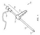
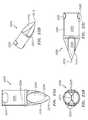
- FIG. 1is an isometric view of an exemplary embodiment of a trocar in accordance with the present invention, for use with penetrating tips constructed in accordance with the invention;
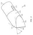
- FIG. 2is an isometric view of one embodiment of a penetrating tip in accordance with the invention, which includes a substantially straight edge;
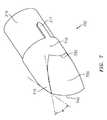
- FIG. 3is an isometric view of the penetrating tip of FIG. 2 , including hidden lines illustrating internal surface geometry of the tip;
- FIG. 4is a side view of the penetrating tip of FIG. 2 , including hidden lines illustrating internal surface geometry;
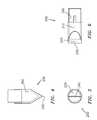
- FIG. 5is an end view of the penetrating tip of FIG. 2 , including hidden lines illustrating internal surface geometry;
- FIG. 6is a top view of the penetrating tip of FIG. 2 , including hidden lines illustrating internal surface geometry;
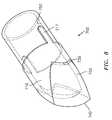
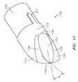
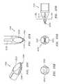
- FIG. 7is an alternate embodiment of a penetrating tip in accordance with the invention, having an arcuate penetrating surface
- FIG. 8is an isometric view of the penetrating tip of FIG. 7 , including hidden lines illustrating internal surface geometry of the tip;
- FIG. 9is a side view of the penetrating tip of FIG. 7 , including hidden lines illustrating internal surface geometry
- FIG. 10is an end view of the penetrating tip of FIG. 7 , including hidden lines illustrating internal surface geometry
- FIG. 11is a top view of the penetrating tip of FIG. 7 , including hidden lines illustrating internal surface geometry;
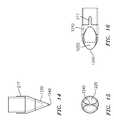
- FIG. 12is a further embodiment of a penetrating tip in accordance with the invention having ovoid facets formed thereon, terminating in an arcuate penetrating edge;
- FIG. 13is an isometric view of the penetrating tip of FIG. 12 , including hidden lines illustrating internal surface geometry of the tip;
- FIG. 14is a side view of the penetrating tip of FIG. 12 , including hidden lines illustrating internal surface geometry;
- FIG. 15is an end view of the penetrating tip of FIG. 12 , including hidden lines illustrating internal surface geometry;
- FIG. 16is a top view of the penetrating tip of FIG. 12 , including hidden lines illustrating internal surface geometry;
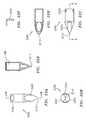
- FIG. 17is another embodiment of a penetrating tip in accordance with the invention having multiple facets on each side thereof, including ovoid facets, and terminating in an arcuate penetrating surface;
- FIG. 18is an isometric view of the penetrating tip of FIG. 17 , including hidden lines illustrating internal surface geometry of the tip;
- FIG. 19is a side view of the penetrating tip of FIG. 17 , including hidden lines illustrating internal surface geometry;
- FIG. 20is an end view of the penetrating tip of FIG. 17 , including hidden lines illustrating internal surface geometry;
- FIG. 21is a top view of the penetrating tip of FIG. 17 , including hidden lines illustrating internal surface geometry;
- FIGS. 22A-22Fare views of a further embodiment of a penetrating tip constructed in accordance with the present invention.
- FIGS. 23A-23Dare further views of the embodiment of FIG. 22 ;
- FIGS. 24A-24Eare views of still another embodiment of a penetrating tip constructed in accordance with the present invention.
- FIGS. 25A-25Eare views of yet another embodiment of a penetrating tip constructed in accordance with the present invention.
- FIGS. 26A-26Eare views of another embodiment of a penetrating tip constructed in accordance with the present invention.
- the present inventionmay be used for insertion of surgical access devices or other devices that require the puncture of biological tissue.
- the present inventionis particularly suited for insertion of surgical access devices or cannulas (or “cannulae”) through the abdominal wall of a patient, in order to provide a working channel through which a surgical procedure can be performed.
- a visualization trocar 100which includes a handle 110 , a shaft 120 extending from the handle 110 , and a penetrating tip 130 arranged at the distal end of the shaft 120 .
- the trocar 100can be used with an endoscope 190 having an eyepiece 193 at a distal end thereof, which receives images through an optical path from a lens (not shown) situated on the endoscope 190 near the penetrating tip 130 .
- Such imagesare typically transmitted by way of a transparent medium within the endoscope 190 , such as an optical shaft or one or more optical fibers.
- an attachment having an image sensorcan be secured to the endoscope 190 on or in place of the eyepiece 193 .
- the endoscope 190can further be provided with a secondary optical conduit 180 , which can transmit light to the penetrating tip 130 .
- the trocar 100can be provided with an integral endoscope, including all of the features thereof contained in one integral device.
- an image sensorcan be provided within the trocar 100 at the distal end thereof—in the shaft 120 or within the penetrating tip 130 . Accordingly, electrical rather than optical connections then extend through the shaft 120 to a display device, such as a video monitor.
- a locking element 170can be provided in the handle portion 110 of the trocar 100 .
- the locking element 170engages the endoscope 190 passing through the handle 110 , to prevent at a minimum, relative axial movement between the trocar 100 and the endoscope 190 . Additionally, relative rotational movement can be inhibited, if desired.
- trocar 100itself can vary, and can include additional features, as needed or desired.
- cannulae utilized with the trocar 100can include one or more demarcations thereon, which indicate the progress of insertion, and can therefore signal to the surgeon when the cannula has been inserted sufficiently.
- the geometry of the penetrating tip 130can change as desired, as will become apparent through understanding of the various embodiments of penetrating tips, which are set forth hereinbelow.
- the term “trocar”is used herein to refer generally to an insertion device, which is capable of puncturing an anatomical structure, such as an abdominal wall, to insert a surgical access device or “port” to aid in performing a surgical procedure.
- FIG. 2an isometric view of an exemplary embodiment of a penetrating tip in accordance with the invention is shown in FIG. 2 and is designated generally by reference number 200 .
- the penetrating tip 200includes a body 210 , at its proximal end having a reduced-diameter portion 219 , and one or more rotation locking elements 217 , each of which interfaces with the shaft of a trocar (e.g., shaft 120 of trocar 100 ).
- a trocare.g., shaft 120 of trocar 100
- the reduced-diameter portion 219is inserted into the shaft of a trocar, thereby enabling secure mutual engagement therebetween, while the rotation locking element(s) 217 engage a mating element, such as a groove, notch or recess in the shaft of the trocar, preventing relative rotation between the penetrating tip 200 and the trocar shaft. If, however, the tip 200 is manufactured integrally with a trocar, relative positioning can be achieved and maintained in another manner, such as integrally molding, insert molding, adhering, bonding or welding the components by heat, solvent or friction, or by another suitable manufacturing technique.
- the distal end of the penetrating tip 200includes a distal taper 215 of the body 210 , and two opposed angled facets 220 , which are angled inwardly, approaching the penetrating edge 240 at the distal end of the tip 200 .
- the facets 220are substantially planar in this embodiment, and are delimited partially by a change in contour indicated by arcuate contour interface 230 with the body 210 , and partially by the distal penetrating edge 240 .
- the facets 220are angled, with respect to one another at an angle ⁇ (alpha).
- the angle ⁇can be anywhere from about 5 degrees to about 90 degrees, inclusive, at any one-degree increment therebetween. In one embodiment, the angle ⁇ is about 30 degrees, and in another embodiment the angle ⁇ is about 40 degrees, for example.
- the tip 200is inserted into a trocar, such as trocar 100 of FIG. 1 , or alternatively is manufactured integrally therewith.
- the tip 200can be manufactured from any suitable material, but is preferably transparent, to allow a surgeon to view the layers of tissue through which the surgeon is penetrating.
- Such materialscan include, for example, polycarbonate plastic, polymethyl methacrylate (“acrylic”), a vitreous material such as glass, or an optical crystal material. Accordingly, the surgeon is able to view the tissue through which the trocar and tip 200 are passing. The surgeon is able, therefore, to determine by the general appearance of the tissue, the point at which the tip 200 has penetrated to a sufficient depth. During an abdominal procedure, the depth will typically be a point at which the tip 200 has just entered the peritoneal cavity.
- the tip 200can be provided with any desired degree of sharpness. That is, the penetrating tip 240 can be formed to have a sharp point, a dissecting edge or can be rounded to any desired degree in order to provide a relatively blunt leading edge. When provided with a relatively blunt tip 240 , accidental injury to internal anatomical structures, such as intestines, can be reduced.
- FIG. 3is an isometric view of the tip of FIG. 2 , including hidden lines illustrating internal surface geometry of the tip 200 .
- an internal surface 350is provided in the penetrating tip 200 .
- This internal surface 350defines a space through which images can be taken.
- a visualization device(not shown) is preferably provided with trocars and penetrating tips in accordance with the invention, including that illustrated in FIGS. 2-6 .
- Various embodimentscan be used to provide an image to the surgeon inserting the trocar.
- an imaging devicesuch as a CCD (charge-coupled device) can be provided in the trocar (e.g., trocar 100 ) or in the penetrating tip (e.g., tip 200 ), or alternatively connected thereto via an optical path, which can include, for example, one or more fiber-optic conduits.
- an optical pathcan include, for example, one or more fiber-optic conduits.
- Such trocarscan also be provided with illumination capability provided through the optical path.
- the internal space defined by the internal surface 350 of the tip 200includes surface features that correspond to features provided on the external surface of the tip 200 .
- an arcuate contour interface 353 and inner facet 352correspond to the arcuate contour interface 230 and the facets 220 of the outer surface of the tip 200 .
- an inner tip 354 of the space defined by the inner surface 350corresponds to the penetrating edge 240 of the outer surface of the tip 200 .
- Such corresponding internal geometrycan reduce distortion in an image obtained from the tip 200 .
- one or more lensescan be additionally provided within the tip 200 , to adjust, correct or direct images as needed.
- FIGS. 4 , 5 and 6are side, end and top views, respectively, of the tip 200 of FIGS. 2 and 3 , including hidden lines illustrating internal surface geometry of the tip 200 .
- any of the features described in connection with any of the following embodimentscan advantageously be applied to this embodiment.
- FIGS. 7-11illustrate an alternate embodiment of a penetrating tip 700 in accordance with the invention, having an arcuate penetrating surface 740 .
- the tip 700includes a body 710 , having at its proximal end a reduced-diameter portion 219 , and one or more rotation locking elements 217 .
- the tip 700is manufactured integrally with a trocar, relative positioning can be achieved and maintained without such locking elements 217 .
- the distal end of the penetrating tip 700includes a distal taper 715 of the body 710 , and two opposed angled facets 720 , which are angled inwardly, approaching the cutting or dissecting edge 740 at the distal end of the tip 700 .
- the facets 720are delimited partially by an arcuate contour interface 730 with the body 210 , and partially by the distal edge 740 .
- the facets 720are convexly contoured, rather than being planar, which can best be seen in the side view of FIG. 9 .
- the facets 720are angled, with respect to one another at an angle ⁇ (alpha).
- the angle ⁇can be, for example, anywhere from about 5 degrees to about 80 degrees.
- FIG. 8is an isometric view of the tip 700 of FIG. 7 , including hidden lines illustrating internal surface geometry of the tip 700 .
- an internal surface 750is formed within the tip 700 , which includes surface features corresponding to features of the outer surface of the tip 700 .
- any of the embodiments set forth hereincan include a solid tip.
- such tipwill include optical elements to enable adequate optical transmission of images from the distal end of the tip 700 .
- an imaging devicesuch as a CCD is provided within the body 710 of the tip 700 at an appropriate location, such as just proximal of the facet 720 , an adequate image can be obtained regardless of the optical characteristics of the remainder of the tip 700 .
- FIGS. 9-11are side, end and top views of the tip 700 of FIGS. 7-8 , including hidden lines illustrating internal surface geometry.
- any of the features described in connection with any other embodiment set forth hereincan advantageously be applied to this embodiment.
- FIGS. 12-16illustrate a further embodiment of a penetrating tip, designated generally with reference number 1200 , in accordance with the invention.
- the tip 1200includes ovoid facets 1120 formed thereon, terminating in an arcuate cutting or dissecting surface 1240 .
- the tip 1200is similar in many respects to the foregoing embodiments.
- the ovoid facets 1220result in a reduced profile for insertion. That is, instead of the relatively wide surfaces 240 , 740 of the above-described tips 200 , 700 , respectively, the cutting or dissecting edge 1240 , at the distal end of the ovoid facets 1220 , is relatively narrow.
- the tip 1200can facilitate initial insertion by reducing the force necessary to puncture the abdominal wall.
- the tapered region 1215 of the body 1210helps widen the initial incision, as the tip 1200 advances through the patient's abdominal wall.
- the ovoid facets 1220can be convex or planar, as desired, and are delimited by the penetrating edge 1240 , and the contour interface 1230 , where the contour of the tip 1200 transitions from the facet 1220 to the relatively cylindrical body 1210 .
- the facets 1220are angled with respect to one another at an angle ⁇ (alpha).
- the angle ⁇can be anywhere from about 5 degrees to about 80 degrees, for example.
- FIG. 13is an isometric view of the tip 1200 of FIG. 12 , including hidden lines illustrating internal surface geometry of the tip 1200 .
- the internal surface 1350 of the tip 1200is visible.
- the internal surface 1350can include features that correspond to features of the outer surface of the tip 1200 .
- the tip 1200can include a contour interface 1353 corresponding to the contour interface 1230 of the outer surface of the tip 1200 , and can include an inner facet 1352 corresponding to the facet 1220 on the outer surface of the tip 1200 .
- FIGS. 14-16are side, end and top views, respectively, of the tip of FIGS. 12-13 , including hidden lines illustrating internal surface geometry.
- FIG. 17-21illustrate another embodiment of a penetrating tip 1700 constructed in accordance with the invention having multiple facets 1721 , 1723 , 1725 on each side thereof, including ovoid facets 1721 , and terminating in an arcuate cutting or dissecting surface 1740 , similar to the embodiment of FIGS. 7-11 .
- the penetrating tip 1700includes a body 1710 , at its proximal end having a reduced-diameter portion 219 , and one or more rotation locking elements 217 , as with the foregoing embodiments.
- the distal end of the penetrating tip 1700includes a distal taper 1715 of the body 1710 , and opposed angled facets 1721 , 1723 , 1725 , which are angled inwardly, approaching the penetrating edge 1740 at the distal end of the penetrating tip 1700 .
- the facets 1721 , 1723 , 1725can be either convex or substantially planar. As illustrated, the facets include a substantially planar facet 1721 , and convex facets 1723 , 1725 , the convexity of which is best seen, for example, in the side view of FIG. 19 .
- the facets 1721 , 1723 , 1725are delimited on one side by the contour interface 1730 and at the other side by the cutting or dissecting edge 1740 .
- the change in contours among adjacent facetsis defined therebetween at a contour interface indicated by line 1732 .
- the facets 1721 of opposite sides of the penetrating tip 1700are angled, with respect to one another at an angle ⁇ (alpha).
- the angle ⁇can be anywhere from about 5 degrees to about 80 degrees, at any one degree increment therebetween, for example.
- the contour interface 1730includes a corresponding inner contour interface 1853 defined on the inner surface 1850 of the tip 1700 , as part of a generally corresponding overall shape.
- FIGS. 19-21are side, end and top views, respectively of the tip 1700 of FIGS. 17 and 18 , including hidden lines illustrating internal surface geometry.
- FIGS. 22A-22F and 23 A-Drepresent further embodiments of a tip 2200 made in accordance with the invention.
- FIG. 22Adepicts a lengthwise view of tip 2200 along one of two opposing substantially ovoid main facets 2220 that converge to a distal dissecting edge 2210 .
- facets 2220are substantially flat, as opposed to concave or convex.
- Additional smaller facets 2225are defined between the main facets 2220 .
- the intervening facets 2225are generally elongate concave formations or grooves. It will be appreciated that each of the facets 2220 , 2225 may be substantially flat, convex or concave, as desired.
- FIG. 22Adepicts a lengthwise view of tip 2200 along one of two opposing substantially ovoid main facets 2220 that converge to a distal dissecting edge 2210 .
- facets 2220are substantially flat, as opposed to concave or convex.
- Additional smaller facets 2225are defined between
- FIG. 22Bdepicts an end view of tip 2200 , showing the manner in which all four facets converge and taper to edge 2210 .
- FIG. 22Cdepicts a lengthwise view of tip 2200 illustrating the shape of facet 2225 .
- FIG. 22Dillustrates a cross sectional view of tip 2200 taken along line “A-A” in FIG. 22C .
- FIG. 22Eillustrates a cross sectional view of tip 2200 taken along line “B-B” in FIG. 22A .
- FIG. 22Fillustrates an enlarged cross sectional view of tip 2200 illustrating a locking feature discussed below.
- FIGS. 23A-Cdepict similar illustrations of tip 2200 showing the interior surfaces of tip 2200 in broken lines.
- FIG. 23Ddepicts an isometric view of tip 2200 .
- tip 2200defines a hollow interior 2250 bound by a plurality of inner surfaces 2260 .
- a locking feature 2230may be provided to facilitate attachment of tip 2200 to a trocar shaft, as described herein.
- the tip 2200may be fully transparent or may include one or more opaque, darkened or otherwise visually obscured regions, such as in the distal region 240 of the tip 2200 , proximate the dissecting edge 2210 in region 2240 . Such regions are illustrated in the embodiments of FIGS. 24-26 and discussed in further detail below, and can improve visibility of the anatomy being penetrated by reducing glare from stray light entering the tip 2200 .
- the integral dissecting edge, whether blunt or otherwise, the inwardly tapered opposed planar facets and the opaque distal tip portion of the penetrating tipcooperate to define a continuous outer surface without any openings therethrough.
- the opaque regionis preferably adapted to extend around the entire periphery of the tip from a portion proximal to the distal end of the tip to and including the distal end of the tip.
- the opaque distal region of the bodycan minimize glare by reducing errant internal reflections within the tip 2200 .
- the opaque distal regionwhich can be colored and in contrast with the remainder of the body of the penetrating tip, can be provided in a manner such that it functions as an indicator or gauge.
- the term opaquegenerally refers to an item that substantially inhibits transmission of light.
- the opaque distal regioncan be black, gray, blue, white, red, green, purple, pink, yellow, orange or any color desired.
- the tipcan be translucent and can be clear or have a color imparted thereon.
- the degree of transluciditycan be selected as desired, and thus may still act to reduce glare and/or to serve as a gauge or guide. It is also conceived that providing the entire tip or only the distal region 2240 of the tip 2200 with a particular color can serve to act as an optical filter to enhance images obtained therethrough.
- the colored or obscured distal region 2240when the colored or obscured distal region 2240 is provided in a trocar used in a surgery, a patient's abdomen can be insufflated normally, and an endoscope inserted through the abdominal wall in a conventional manner. Then, when a trocar having a penetrating tip constructed in accordance with the invention is inserted through the abdominal wall, upon reaching the peritoneum, the distal region (having a color, or other feature), becomes readily visible to the surgeon. This is possible only if the surgeon views the procedure through the endoscope already inserted through the abdominal wall. This, however, may require two separate people to view two separate endoscopes.
- FIGS. 24A-24Ddepict still another embodiment of a tip 2400 made in accordance with the present invention having a plurality of facets 2420 , 2425 similar to the embodiment of FIGS. 22-23 and defining a dissecting edge 2410 .
- facets 2420are generally flat surfaces
- facets 2425are generally concave grooves.
- Locking features 2430are further provided to facilitate a connection with a trocar tube.
- a distal region 2440is provided that is generally pyramidal shaped to ease penetration in tissue. As depicted, the distal region 2440 can be darkened, opaque or otherwise obscured, such as by a coating applied thereto, for example, or in another manner.
- Such an obscured or opaque regioncan help reduce the effects of internal reflections in the tip 2400 , thus improving viewing.
- all tips disclosed hereinmay be provided with such an opaque, or otherwise obscured distal region, as desired.
- the opaque or obscured regionmay be made by depositing an opaque material on the surface of the tip 2400 in region 2440 , such as by screen printing or painting.
- such a regionmay be provided by treating the surface of the tip to be obscured such as by roughening to substantially prevent light from passing through the region 2440 .
- the obscured region 2440can be separately formed of an opaque material and combined, by insert molding or other suitable manufacturing technique, with the remaining material of the tip 2400 .
- the region 2440may be treated by providing a second material within the material of the tip 2400 in the region 2440 in order to darken the region 2440 .
- the tip 2400is preferably hollow as with the foregoing embodiments, in order to ease image transmission and to accommodate an endoscope therein for transmitting and receiving light.
- FIGS. 25A-25Dillustrate still another embodiment of a tip 2500 made in accordance with the invention.
- the tip 2500includes two facets 2520 similar to the embodiments of FIGS. 22-24 .
- Tip 2500further includes a generally pyramidal distal region 2540 that is opaque or otherwise obscured. It will be understood that the entirety of tip 2500 may alternatively be transparent, as desired.
- the distal region 2540terminates in a tissue separating edge 2510 and locking feature 2530 as with other embodiments described herein.
- tip 2500further includes two longitudinal depressions 2545 formed therein. Depressions 2545 may facilitate advancement of tip 2500 through tissue by lowering resistance.
- depressions 2545may be obscured and/or provided with an opaque coating to improve the optical performance of tip 2500 .
- the tip 2500is preferably hollow to accommodate an endoscope, and can be provided with optical features to enhance images obtained therefrom.
- FIGS. 26A-26Eillustrate yet another embodiment of a tip 2600 made in accordance with the invention.
- Tip 2600includes a plurality of facets 2620 (four identical facets, as depicted) that join each other at edges 2622 and taper to form a distal region 2640 terminating at a penetrating edge 2610 .
- distal region 2640is obscured or opaque, but may be transparent if desired.
- a locking feature 2630may further be provided, if desired.
- the cross section of tip 2600closely resembles a rectangle with inwardly bowed sides. Such a geometry effectively forms four concave facets 2620 with a reduced cross sectional profile that can facilitate advancement of tip 2600 through tissue by lowering insertion resistance.
- Tip 2600is preferably hollow to accommodate an endoscope.
- Imagescan be output from the aforementioned devices—that is in the penetrating tips or in the trocars, for example.
- the imagescan be displayed for the surgeon on a monitor arranged in a convenient location. If so-desired, a monitor can be provided at and integrated with the proximal end of the trocar itself, so as to enhance the perception and ergonomic aspects of trocars in accordance with the invention. If so-equipped, the proximal end of the trocar can be configured so as to include one or more integral handles to facilitate gripping of the trocar by the surgeon.
- imagescan be automatically manipulated in real time by a computer, prior to display, so as to reduce or eliminate any distortion, color imbalance or other optical aberrations which may be present in the raw image output from the image sensor.
- Penetrating tips and trocars in accordance with the inventioncan be used to create an opening in an anatomical structure of a patient, such in the patient's abdominal wall.
- the openingcan be used to provide access or any of a variety of instruments, such as, for example, a feeding tube.
- devices constructed in accordance with the inventionwill be used to insert surgical access devices, such as access ports and cannulas, which maintain the opening formed by a trocar and therefore provide easy access to a surgical cavity.
- surgical access devicessuch as access ports and cannulas, which maintain the opening formed by a trocar and therefore provide easy access to a surgical cavity.
- Access devices described in the aforementioned applicationinclude various types of seals to inhibit escape of insufflation gas from a patient's peritoneal cavity during a surgical procedure. Additionally, devices constructed in accordance with the invention can be used to insert flexible access devices, such as those set forth in the application entitled “Elastically Deformable Surgical Access Device” U.S. patent application Ser. No. 11/544,856, filed Oct. 6, 2006, which application is also incorporated herein by reference in its entirety. If used with such elastically deformable surgical access devices, engagement elements can be provided on the trocar or the penetrating tip to enable engagement with such access device.
- a trocar having a tip in accordance with the inventionis used to pierce the abdominal wall of the patient.
- the surgeonis able to view the tissue being penetrated by the penetrating tip through any of the aforementioned means, such as through a video monitor.
- a surgical access deviceas those described above, will be inserted simultaneously through the opening created by the trocar.
- the trocar with the penetrating tipis inserted through the access device such that the penetrating tip protrudes from the end of the access port, and the penetrating tip, surrounded by the access port, is inserted through the abdominal wall.
- a scalpelis used to make an incision through the skin, and the penetrating tip with the trocar and access port is inserted through the remaining layers of tissue into the abdominal wall. The trocar is then removed, leaving the surgical access device in place in order to carry out the prescribed surgical procedure.
- the present inventionencompasses methods of use of the devices described herein.
- the present inventionincludes methods of use of penetrating tips described herein, in combination with insertion devices, such as trocars or obturators, and surgical access devices, such as cannulas.
- the present inventioncan relate to a kit having one or more of a penetrating tip in accordance with the invention, a surgical access device, such as a cannula, and an insertion device, such as a trocar or obturator.
Landscapes
- Health & Medical Sciences (AREA)
- Surgery (AREA)
- Life Sciences & Earth Sciences (AREA)
- Medical Informatics (AREA)
- Nuclear Medicine, Radiotherapy & Molecular Imaging (AREA)
- Engineering & Computer Science (AREA)
- Biomedical Technology (AREA)
- Heart & Thoracic Surgery (AREA)
- Pathology (AREA)
- Molecular Biology (AREA)
- Animal Behavior & Ethology (AREA)
- General Health & Medical Sciences (AREA)
- Public Health (AREA)
- Veterinary Medicine (AREA)
- Endoscopes (AREA)
- Surgical Instruments (AREA)
Abstract
Description
Claims (24)
Priority Applications (4)
| Application Number | Priority Date | Filing Date | Title |
|---|---|---|---|
| US11/973,123US8317815B2 (en) | 2006-10-06 | 2007-10-05 | Visualization trocar |
| US29/359,636USD663838S1 (en) | 2007-10-05 | 2010-04-13 | Visualization trocar |
| US29/366,388USD667954S1 (en) | 2007-10-05 | 2010-07-23 | Visualization trocar |
| US12/950,684US20110125084A1 (en) | 2003-04-08 | 2010-11-19 | Trocar assembly with pneumatic sealing |
Applications Claiming Priority (3)
| Application Number | Priority Date | Filing Date | Title |
|---|---|---|---|
| US85000606P | 2006-10-06 | 2006-10-06 | |
| US92392107P | 2007-04-17 | 2007-04-17 | |
| US11/973,123US8317815B2 (en) | 2006-10-06 | 2007-10-05 | Visualization trocar |
Related Parent Applications (1)
| Application Number | Title | Priority Date | Filing Date |
|---|---|---|---|
| US29/359,636Continuation-In-PartUSD663838S1 (en) | 2007-10-05 | 2010-04-13 | Visualization trocar |
Related Child Applications (3)
| Application Number | Title | Priority Date | Filing Date |
|---|---|---|---|
| US10/441,149Continuation-In-PartUS7182752B2 (en) | 2003-04-08 | 2003-05-17 | Continuous gas flow trocar assembly |
| US29/359,636Continuation-In-PartUSD663838S1 (en) | 2007-10-05 | 2010-04-13 | Visualization trocar |
| US29/366,388Continuation-In-PartUSD667954S1 (en) | 2007-10-05 | 2010-07-23 | Visualization trocar |
Publications (2)
| Publication Number | Publication Date |
|---|---|
| US20080086160A1 US20080086160A1 (en) | 2008-04-10 |
| US8317815B2true US8317815B2 (en) | 2012-11-27 |
Family
ID=39134626
Family Applications (1)
| Application Number | Title | Priority Date | Filing Date |
|---|---|---|---|
| US11/973,123Expired - Fee RelatedUS8317815B2 (en) | 2003-04-08 | 2007-10-05 | Visualization trocar |
Country Status (3)
| Country | Link |
|---|---|
| US (1) | US8317815B2 (en) |
| EP (2) | EP2068732B1 (en) |
| WO (1) | WO2008045316A2 (en) |
Cited By (20)
| Publication number | Priority date | Publication date | Assignee | Title |
|---|---|---|---|---|
| US8517977B2 (en) | 2006-10-06 | 2013-08-27 | Applied Medical Resources Corporation | Visual insufflation port |
| US20130331773A1 (en)* | 2012-06-06 | 2013-12-12 | Covidien Lp | Obturator tip with insufflation pathway |
| US8608769B2 (en) | 2001-09-24 | 2013-12-17 | Applied Medical Resources Corporation | Bladeless optical obturator |
| US8608768B2 (en) | 2002-05-16 | 2013-12-17 | Applied Medical Resources Corporation | Blunt tip obturator |
| US8636759B2 (en) | 2001-09-24 | 2014-01-28 | Applied Medical Resources Corporation | Bladeless obturator |
| US9155558B2 (en) | 2004-06-29 | 2015-10-13 | Applied Medical Resources Corporation | Insufflating optical surgical instrument |
| US9254148B2 (en) | 2011-05-02 | 2016-02-09 | Applied Medical Resources Corporation | Low-profile surgical universal access port |
| US9265899B2 (en) | 2008-01-25 | 2016-02-23 | Applied Medical Resources Corporation | Insufflating access system |
| US9314266B2 (en) | 2008-09-29 | 2016-04-19 | Applied Medical Resources Corporation | First-entry trocar system |
| WO2016122937A1 (en) | 2015-01-30 | 2016-08-04 | Surgiquest, Inc. | Self-adjusting pneumatically sealed trocar |
| US9439667B2 (en) | 2002-05-31 | 2016-09-13 | Vidacare LLC | Apparatus and methods to install, support and/or monitor performance of intraosseous devices |
| US9545264B2 (en) | 2014-06-06 | 2017-01-17 | Surgiquest, Inc. | Trocars and obturators |
| US9907569B2 (en) | 2006-10-06 | 2018-03-06 | Conmed Corporation | Trocar assembly with pneumatic sealing |
| US11103282B1 (en) | 2002-05-31 | 2021-08-31 | Teleflex Life Sciences Limited | Powered drivers, intraosseous devices and methods to access bone marrow |
| US11234683B2 (en) | 2002-05-31 | 2022-02-01 | Teleflex Life Sciences Limited | Assembly for coupling powered driver with intraosseous device |
| US11266441B2 (en) | 2002-05-31 | 2022-03-08 | Teleflex Life Sciences Limited | Penetrator assembly for accessing bone marrow |
| US11324521B2 (en) | 2002-05-31 | 2022-05-10 | Teleflex Life Sciences Limited | Apparatus and method to access bone marrow |
| US11337728B2 (en) | 2002-05-31 | 2022-05-24 | Teleflex Life Sciences Limited | Powered drivers, intraosseous devices and methods to access bone marrow |
| US11426249B2 (en) | 2006-09-12 | 2022-08-30 | Teleflex Life Sciences Limited | Vertebral access system and methods |
| US11771439B2 (en) | 2007-04-04 | 2023-10-03 | Teleflex Life Sciences Limited | Powered driver |
Families Citing this family (47)
| Publication number | Priority date | Publication date | Assignee | Title |
|---|---|---|---|---|
| US11298202B2 (en) | 2002-05-31 | 2022-04-12 | Teleflex Life Sciences Limited | Biopsy devices and related methods |
| US7854724B2 (en) | 2003-04-08 | 2010-12-21 | Surgiquest, Inc. | Trocar assembly with pneumatic sealing |
| US7470230B2 (en) | 2005-03-31 | 2008-12-30 | Tyco Healthcare Group Lp | Optical obturator |
| EP2073728B1 (en)* | 2006-09-12 | 2018-11-07 | Teleflex Medical Devices S.à.r.l. | Biopsy device |
| EP3189787B1 (en) | 2006-09-12 | 2019-01-09 | Teleflex Medical Devices S.à.r.l. | Medical procedures trays and related methods |
| WO2008045316A2 (en) | 2006-10-06 | 2008-04-17 | Surgiquest, Incorporated | Visualization trocar |
| AU2008202266B2 (en)* | 2007-06-01 | 2013-09-12 | Covidien Lp | Obturator tips |
| USD663838S1 (en) | 2007-10-05 | 2012-07-17 | Surgiquest, Inc. | Visualization trocar |
| USD667954S1 (en)* | 2007-10-05 | 2012-09-25 | Surgiquest, Inc. | Visualization trocar |
| JP5733831B2 (en) | 2008-10-10 | 2015-06-10 | サージクェスト,インコーポレーテッド | System and method for improved gas recirculation in a surgical trocar with a gas sealing mechanism |
| EP3181074A1 (en)* | 2009-01-30 | 2017-06-21 | St. Jude Medical, Inc. | Transapical mini-introducer homeostasis valve and punch |
| JP5654568B2 (en)* | 2009-04-15 | 2015-01-14 | コーニンクレッカ フィリップス エヌ ヴェ | Needle with fiber incorporated into bevel cutting facet |
| EP2494912A4 (en)* | 2009-10-27 | 2013-06-05 | Panasonic Corp | INTRAORAL CAMERA |
| KR101689250B1 (en) | 2009-12-10 | 2016-12-23 | 알콘 리서치, 리미티드 | Multi-spot laser surgical probe using faceted optical elements |
| WO2011130399A1 (en)* | 2010-04-13 | 2011-10-20 | Surgiquest, Incorporated | Visualization trocar |
| GB201016056D0 (en)* | 2010-09-24 | 2010-11-10 | Surgical Innovations Ltd | Trocar tip |
| GB2492987A (en)* | 2011-07-19 | 2013-01-23 | Surgical Innovations Ltd | Optical trocar assembly |
| US9216067B2 (en) | 2011-09-23 | 2015-12-22 | Gholam A. Peyman | Vitreous cutter sleeve and a vitreous cutter system using the same |
| US8979867B2 (en)* | 2011-09-23 | 2015-03-17 | Gholam A. Peyman | Vitreous cutter |
| US10117703B2 (en)* | 2011-10-17 | 2018-11-06 | Beaver-Visitec International (Us), Inc. | Method of, and device for, marking a patients eye for reference during a toric lens implantation procedure |
| ES2769810T3 (en)* | 2011-10-18 | 2020-06-29 | Covidien Lp | Optical trocar system |
| US9308128B2 (en) | 2013-01-08 | 2016-04-12 | Novartis Ag | Multi-spot laser probe with micro-structured faceted proximal surface |
| BR112015022987A2 (en)* | 2013-03-15 | 2017-07-18 | Olive Medical Corp | integrated prism trocar visualization for use with angled endoscope |
| AU2015258930A1 (en)* | 2014-05-15 | 2016-11-24 | Smith & Nephew, Inc. | Tissue graft fixation with tension adjustment |
| DE102014118575B4 (en)* | 2014-12-12 | 2016-10-06 | Carl Zeiss Meditec Ag | Surgical instrument |
| CN112998807B (en) | 2015-02-13 | 2024-07-05 | 瑟西纳斯医疗技术有限责任公司 | System and method for placement of medical devices in bone |
| US10117675B2 (en)* | 2015-07-28 | 2018-11-06 | Covidien Lp | Trocar tip protector |
| US20240074640A1 (en)* | 2015-08-17 | 2024-03-07 | Rebound Therapeutics Corporation | Cannula and Obturator with a Transparent Tip with an Opaque Component |
| US20180147328A1 (en)* | 2015-09-02 | 2018-05-31 | MicroAire Surgical Instruments, LLC. | Endoscopic Surgical Devices and Other Surgical Devices and Methods of Making, Especially Using Polyarylamides, Polyetherimides, Polyether Ether Ketones, and Liquid Crystal Polymers |
| US20170056047A1 (en)* | 2015-09-02 | 2017-03-02 | MicroAire Surgical Instruments, LLC. | Endoscopic Surgical Devices and Other Surgical Devices |
| KR102486092B1 (en)* | 2016-08-17 | 2023-01-06 | 리바운드 세라퓨틱스 코포레이션 | Cannula with Proximally Mounted Camera |
| GB2553045B (en)* | 2016-08-17 | 2019-02-13 | Rebound Therapeutics Corp | Cannula with proximally mounted camera |
| US10105042B2 (en) | 2016-08-17 | 2018-10-23 | Rebound Therapeutics Corporation | Cannula with proximally mounted camera |
| WO2018170549A1 (en)* | 2017-03-23 | 2018-09-27 | Medlogical Innovations Pty Ltd | Device for interstitial laser therapy |
| WO2019036524A1 (en) | 2017-08-14 | 2019-02-21 | Scapa Flow, Llc | System and method using augmented reality with shape alignment for medical device placement in bone |
| US10722111B2 (en) | 2018-03-13 | 2020-07-28 | Covidien Lp | Optical trocar assembly |
| US11986423B1 (en) | 2018-06-18 | 2024-05-21 | Gholam A. Peyman | Method of using a vitrectomy instrument |
| US11020270B1 (en) | 2018-06-18 | 2021-06-01 | Gholam A. Peyman | Vitrectomy instrument and a system including the same |
| US10736659B2 (en) | 2018-10-23 | 2020-08-11 | Covidien Lp | Optical trocar assembly |
| CA3130085A1 (en)* | 2019-02-22 | 2020-08-27 | Rebound Therapeutics Corporation | Cannula and obturator with a transparent tip with an opaque component |
| CN109771036B (en)* | 2019-03-15 | 2021-10-29 | 上海电气集团股份有限公司 | End effector device |
| AU2020257211A1 (en) | 2019-04-15 | 2021-11-11 | Circinus Medical Technology Llc | Orientation calibration system for image capture |
| US11357542B2 (en) | 2019-06-21 | 2022-06-14 | Covidien Lp | Valve assembly and retainer for surgical access assembly |
| AU2019458295B2 (en) | 2019-07-24 | 2025-02-27 | Medlogical Innovations Pty Ltd | System with cooling fluid for interstitial laser therapy |
| AU2021383765A1 (en) | 2020-11-19 | 2023-06-22 | Circinus Medical Technology Llc | Systems and methods for artificial intelligence based image analysis for placement of surgical appliance |
| US12064186B2 (en) | 2021-02-02 | 2024-08-20 | Circinus Medical Technology Llc | Systems and methods for simulating three-dimensional orientations of surgical hardware devices about an insertion point of an anatomy |
| WO2022221449A1 (en) | 2021-04-14 | 2022-10-20 | Circinus Medical Technology Llc | System and method for lidar-based anatomical mapping |
Citations (74)
| Publication number | Priority date | Publication date | Assignee | Title |
|---|---|---|---|---|
| US3224320A (en) | 1959-05-05 | 1965-12-21 | Slagteriernes Forskningsinst | Apparatus for determination of the distribution of meat and fat in slaughtered animals or parts thereof |
| US3357433A (en) | 1962-12-04 | 1967-12-12 | Centre Nat Rech Scient | Endoscope for illumination and observation of contacting distal regions |
| US3459189A (en) | 1965-07-28 | 1969-08-05 | Brunswick Corp | Trocar catheter |
| US3556085A (en) | 1968-02-26 | 1971-01-19 | Olympus Optical Co | Optical viewing instrument |
| DE2538758A1 (en) | 1975-08-30 | 1977-03-10 | Eberhard Dr Med Regenbogen | Rectoscope obturator with transparent bolt - is coupled to annular end piece over thin parallel connecting rods |
| US4191191A (en) | 1978-02-13 | 1980-03-04 | Auburn Robert M | Laproscopic trocar |
| DE2847561A1 (en) | 1978-11-02 | 1980-05-08 | Wolf Gmbh Richard | Endoscopic length measurement without gauge rods or discs - using endoscope attachment with measurement plate viewed with object |
| US4319563A (en) | 1977-12-02 | 1982-03-16 | Olympus Optical Co., Ltd. | Endoscope with a smoothly curved distal end face |
| GB2173312A (en) | 1985-04-06 | 1986-10-08 | Wolf Gmbh Richard | Endoscope |
| US5057082A (en) | 1988-11-04 | 1991-10-15 | Plastic Injectors, Inc. | Trocar assembly |
| US5058603A (en) | 1988-08-09 | 1991-10-22 | Asahi Kogaku Kogyo K.K. | Length-measuring device and reference color display device for color tone adjustment for use in combination with endoscope |
| US5066288A (en)* | 1988-07-06 | 1991-11-19 | Ethicon, Inc. | Safety trocar |
| DE4133073A1 (en) | 1990-10-11 | 1992-04-16 | Effner Gmbh | Trocar for producing access for surgery under endoscopic control - has pointed tip at one end of shaft and optical system with objective in vicinity to tip |
| US5122122A (en) | 1989-11-22 | 1992-06-16 | Dexide, Incorporated | Locking trocar sleeve |
| US5147376A (en) | 1990-05-04 | 1992-09-15 | Francesco Pianetti | Trocar needle laparoscopy with a threaded truncated cone bit |
| US5159920A (en) | 1990-06-18 | 1992-11-03 | Mentor Corporation | Scope and stent system |
| US5256149A (en) | 1992-02-14 | 1993-10-26 | Ethicon, Inc. | Trocar having transparent cannula and method of using |
| US5271380A (en) | 1990-11-06 | 1993-12-21 | Siegfried Riek | Penetration instrument |
| EP0577400A1 (en) | 1992-06-30 | 1994-01-05 | Ethicon, Inc. | Flexible endoscopic surgical port |
| US5290276A (en) | 1992-02-06 | 1994-03-01 | Sewell Jr Frank | Rotatable laparoscopic puncturing instrument |
| WO1994011040A1 (en) | 1992-11-17 | 1994-05-26 | Kaali Steven G | Visually directed trocar and method |
| US5330437A (en) | 1993-11-12 | 1994-07-19 | Ethicon Endo-Surgery | Self sealing flexible elastomeric valve and trocar assembly for incorporating same |
| US5342383A (en)* | 1992-03-27 | 1994-08-30 | Thomas Medical Products, Inc. | Soft tip obturator |
| US5385572A (en) | 1992-11-12 | 1995-01-31 | Beowulf Holdings | Trocar for endoscopic surgery |
| US5391153A (en) | 1993-04-09 | 1995-02-21 | Habley Medical Technology Corporation | Trocar with linear movement seal |
| US5405328A (en) | 1992-06-17 | 1995-04-11 | Minnesota Mining And Manufacturing Company | Trocar with replaceable obturator |
| EP0664992A1 (en) | 1994-01-26 | 1995-08-02 | PARTOMED Medizintechnik GmbH | Instrument for penetrating body tissue |
| US5441041A (en) | 1993-09-13 | 1995-08-15 | United States Surgical Corporation | Optical trocar |
| US5445142A (en) | 1994-03-15 | 1995-08-29 | Ethicon Endo-Surgery, Inc. | Surgical trocars having optical tips defining one or more viewing ports |
| US5467762A (en) | 1993-09-13 | 1995-11-21 | United States Surgical Corporation | Optical trocar |
| US5545150A (en) | 1994-05-06 | 1996-08-13 | Endoscopic Concepts, Inc. | Trocar |
| US5562696A (en) | 1992-11-12 | 1996-10-08 | Cordis Innovasive Systems, Inc. | Visualization trocar |
| US5569292A (en)* | 1995-02-01 | 1996-10-29 | Ethicon Endo-Surgery, Inc. | Surgical penetration instrument with transparent blades and tip cover |
| US5569291A (en) | 1995-02-01 | 1996-10-29 | Ethicon Endo-Surgery, Inc. | Surgical penetration and dissection instrument |
| US5591192A (en) | 1995-02-01 | 1997-01-07 | Ethicon Endo-Surgery, Inc. | Surgical penetration instrument including an imaging element |
| US5607441A (en) | 1995-03-24 | 1997-03-04 | Ethicon Endo-Surgery, Inc. | Surgical dissector |
| US5609562A (en) | 1993-11-16 | 1997-03-11 | Worldwide Optical Trocar Licensing Corporation | Visually directed trocar and method |
| US5624459A (en) | 1995-01-26 | 1997-04-29 | Symbiosis Corporation | Trocar having an improved cutting tip configuration |
| US5647840A (en) | 1994-09-14 | 1997-07-15 | Circon Corporation | Endoscope having a distally heated distal lens |
| US5690664A (en) | 1993-09-13 | 1997-11-25 | United States Surgical Corporation | Trocar having movable blade |
| US5697913A (en) | 1996-08-09 | 1997-12-16 | Ethicon Endo-Surgery, Inc. | Trocar including cannula with stepped region |
| US5720761A (en) | 1993-11-16 | 1998-02-24 | Worldwide Optical Trocar Licensing Corp. | Visually directed trocar and method |
| US5738628A (en) | 1995-03-24 | 1998-04-14 | Ethicon Endo-Surgery, Inc. | Surgical dissector and method for its use |
| US5779728A (en) | 1991-05-29 | 1998-07-14 | Origin Medsystems, Inc. | Method and inflatable chamber apparatus for separating layers of tissue |
| US5800451A (en) | 1994-01-18 | 1998-09-01 | Willy Rusch Ag | Trocar system |
| US5817061A (en)* | 1997-05-16 | 1998-10-06 | Ethicon Endo-Surgery, Inc. | Trocar assembly |
| US5817062A (en) | 1996-03-12 | 1998-10-06 | Heartport, Inc. | Trocar |
| US5860996A (en) | 1994-05-26 | 1999-01-19 | United States Surgical Corporation | Optical trocar |
| US5951464A (en) | 1991-06-05 | 1999-09-14 | Asahi Kogaku Kogyo Kabushiki Kaisha | Distal end part of endoscope |
| US5976168A (en) | 1995-07-13 | 1999-11-02 | Origin Medsystems, Inc. | Tissue separation cannula |
| US6017356A (en) | 1997-09-19 | 2000-01-25 | Ethicon Endo-Surgery Inc. | Method for using a trocar for penetration and skin incision |
| US6203568B1 (en)* | 1996-04-05 | 2001-03-20 | Medtronic, Inc. | Endoluminal prostheses having position indicating markers |
| US6206823B1 (en) | 1999-08-02 | 2001-03-27 | Ethicon Endo-Surgery, Inc. | Surgical instrument and method for endoscopic tissue dissection |
| USD443360S1 (en) | 2000-03-22 | 2001-06-05 | Dexterity Surgical Inc. | Distal end of obturator for a trocar |
| US6283948B1 (en) | 1999-07-13 | 2001-09-04 | Ethicon, Inc. | Trocar obturator having grooved passageway |
| US20020013597A1 (en) | 2000-05-16 | 2002-01-31 | Mcfarlane Richard H. | Penetrating tip for trocar assembly |
| US6439541B1 (en) | 1999-06-02 | 2002-08-27 | Olympus Winter & Ibe Gmbh | Trocar sleeve with a duckbill valve |
| US6471638B1 (en) | 2000-04-28 | 2002-10-29 | Origin Medsystems, Inc. | Surgical apparatus |
| US6613063B1 (en) | 2000-10-03 | 2003-09-02 | Daniel Hunsberger | Trocar assembly |
| US6692467B2 (en) | 2000-05-31 | 2004-02-17 | Taut, Inc. | Trocar assembly |
| US6830578B2 (en) | 2001-11-26 | 2004-12-14 | Neosurg Technologies, Inc. | Trocar |
| US6835201B2 (en)* | 2001-03-15 | 2004-12-28 | Neosurg Technologies, Inc. | Trocar |
| US6863674B2 (en) | 2001-12-28 | 2005-03-08 | Olympus Corporation | Operating trocar |
| US20050075605A1 (en) | 1999-04-16 | 2005-04-07 | Lyon Thomas R. | Clear view cannula |
| US6884253B1 (en) | 2000-05-16 | 2005-04-26 | Taut, Inc. | Penetrating tip for trocar assembly |
| US20050107816A1 (en)* | 2001-09-24 | 2005-05-19 | Pingleton Edward D. | Bladeless obturator |
| US6908454B2 (en) | 2002-02-15 | 2005-06-21 | Taut, Inc. | Anchoring assembly for a medical instrument |
| US6918871B2 (en) | 2003-06-19 | 2005-07-19 | Ethicon Endo-Surgery, Inc. | Method for accessing cavity |
| US6939296B2 (en) | 2001-10-17 | 2005-09-06 | Applied Medical Resources Corp. | Laparoscopic illumination apparatus and method |
| US6960164B2 (en) | 2003-08-01 | 2005-11-01 | Neosurg Technologies, Inc. | Obturator tip for a trocar |
| US20050251190A1 (en) | 2000-05-16 | 2005-11-10 | Mcfarlane Richard H | Penetrating tip for trocar assembly |
| EP1685792A1 (en) | 2005-01-28 | 2006-08-02 | Tyco Healthcare Group Lp | Optical penetrating adapter for surgical portal |
| EP1707132A2 (en) | 2005-03-31 | 2006-10-04 | Tyco Healthcare Group Lp | Optical obturator |
| US20080086160A1 (en) | 2006-10-06 | 2008-04-10 | Surgiquest, Incorporated | Visualization trocar |
- 2007
- 2007-10-05WOPCT/US2007/021387patent/WO2008045316A2/enactiveApplication Filing
- 2007-10-05USUS11/973,123patent/US8317815B2/ennot_activeExpired - Fee Related
- 2007-10-05EPEP07839288.3Apatent/EP2068732B1/enactiveActive
- 2007-10-05EPEP12184667.9Apatent/EP2537477B1/enactiveActive
Patent Citations (101)
| Publication number | Priority date | Publication date | Assignee | Title |
|---|---|---|---|---|
| US3224320A (en) | 1959-05-05 | 1965-12-21 | Slagteriernes Forskningsinst | Apparatus for determination of the distribution of meat and fat in slaughtered animals or parts thereof |
| US3357433A (en) | 1962-12-04 | 1967-12-12 | Centre Nat Rech Scient | Endoscope for illumination and observation of contacting distal regions |
| US3459189A (en) | 1965-07-28 | 1969-08-05 | Brunswick Corp | Trocar catheter |
| US3556085A (en) | 1968-02-26 | 1971-01-19 | Olympus Optical Co | Optical viewing instrument |
| DE2538758A1 (en) | 1975-08-30 | 1977-03-10 | Eberhard Dr Med Regenbogen | Rectoscope obturator with transparent bolt - is coupled to annular end piece over thin parallel connecting rods |
| US4319563A (en) | 1977-12-02 | 1982-03-16 | Olympus Optical Co., Ltd. | Endoscope with a smoothly curved distal end face |
| US4191191A (en) | 1978-02-13 | 1980-03-04 | Auburn Robert M | Laproscopic trocar |
| DE2847561A1 (en) | 1978-11-02 | 1980-05-08 | Wolf Gmbh Richard | Endoscopic length measurement without gauge rods or discs - using endoscope attachment with measurement plate viewed with object |
| GB2173312A (en) | 1985-04-06 | 1986-10-08 | Wolf Gmbh Richard | Endoscope |
| US5066288A (en)* | 1988-07-06 | 1991-11-19 | Ethicon, Inc. | Safety trocar |
| US5058603A (en) | 1988-08-09 | 1991-10-22 | Asahi Kogaku Kogyo K.K. | Length-measuring device and reference color display device for color tone adjustment for use in combination with endoscope |
| US5057082A (en) | 1988-11-04 | 1991-10-15 | Plastic Injectors, Inc. | Trocar assembly |
| US5122122A (en) | 1989-11-22 | 1992-06-16 | Dexide, Incorporated | Locking trocar sleeve |
| US5147376A (en) | 1990-05-04 | 1992-09-15 | Francesco Pianetti | Trocar needle laparoscopy with a threaded truncated cone bit |
| US5159920A (en) | 1990-06-18 | 1992-11-03 | Mentor Corporation | Scope and stent system |
| DE4133073A1 (en) | 1990-10-11 | 1992-04-16 | Effner Gmbh | Trocar for producing access for surgery under endoscopic control - has pointed tip at one end of shaft and optical system with objective in vicinity to tip |
| US5271380A (en) | 1990-11-06 | 1993-12-21 | Siegfried Riek | Penetration instrument |
| US5685820A (en)* | 1990-11-06 | 1997-11-11 | Partomed Medizintechnik Gmbh | Instrument for the penetration of body tissue |
| US6007481A (en) | 1990-11-06 | 1999-12-28 | Riek; Siegfried | Instrument for the penetration of body tissue with cutting and viewing of body structure |
| EP0484725B1 (en) | 1990-11-06 | 1996-03-27 | PARTOMED Medizintechnik GmbH | Instrument for penetrating body tissue |
| US5431151A (en) | 1990-11-06 | 1995-07-11 | Partomed Medizintechnik Gmbh | Instrument for the penetration of body tissue |
| US5779728A (en) | 1991-05-29 | 1998-07-14 | Origin Medsystems, Inc. | Method and inflatable chamber apparatus for separating layers of tissue |
| US5951464A (en) | 1991-06-05 | 1999-09-14 | Asahi Kogaku Kogyo Kabushiki Kaisha | Distal end part of endoscope |
| US5290276A (en) | 1992-02-06 | 1994-03-01 | Sewell Jr Frank | Rotatable laparoscopic puncturing instrument |
| US5256149A (en) | 1992-02-14 | 1993-10-26 | Ethicon, Inc. | Trocar having transparent cannula and method of using |
| US5342383A (en)* | 1992-03-27 | 1994-08-30 | Thomas Medical Products, Inc. | Soft tip obturator |
| US5405328A (en) | 1992-06-17 | 1995-04-11 | Minnesota Mining And Manufacturing Company | Trocar with replaceable obturator |
| EP0577400A1 (en) | 1992-06-30 | 1994-01-05 | Ethicon, Inc. | Flexible endoscopic surgical port |
| EP0577400B1 (en) | 1992-06-30 | 1999-10-27 | Ethicon, Inc. | Flexible endoscopic surgical port |
| US5385572A (en) | 1992-11-12 | 1995-01-31 | Beowulf Holdings | Trocar for endoscopic surgery |
| US5797944A (en)* | 1992-11-12 | 1998-08-25 | Ethicon Endo-Surgery, Inc. | Visualization trocar |
| US5562696A (en) | 1992-11-12 | 1996-10-08 | Cordis Innovasive Systems, Inc. | Visualization trocar |
| US5380291A (en) | 1992-11-17 | 1995-01-10 | Kaali; Steven G. | Visually directed trocar for laparoscopic surgical procedures and method of using same |
| US5376076A (en) | 1992-11-17 | 1994-12-27 | Kaali; Steven G. | Visually directed trocar for laparoscopic surgical procedures and method of using same |
| US5334150A (en)* | 1992-11-17 | 1994-08-02 | Kaali Steven G | Visually directed trocar for laparoscopic surgical procedures and method of using same |
| WO1994011040A1 (en) | 1992-11-17 | 1994-05-26 | Kaali Steven G | Visually directed trocar and method |
| US5551947A (en) | 1992-11-17 | 1996-09-03 | Worldwide Optical Trocar Licensing Corporation | Visually directed trocar for laparoscopic surgical procedures and method of using same |
| US5391153A (en) | 1993-04-09 | 1995-02-21 | Habley Medical Technology Corporation | Trocar with linear movement seal |
| US5690664A (en) | 1993-09-13 | 1997-11-25 | United States Surgical Corporation | Trocar having movable blade |
| US5658236A (en) | 1993-09-13 | 1997-08-19 | United States Surgical Corporation | Optical trocar |
| US20050261717A1 (en) | 1993-09-13 | 2005-11-24 | Sauer Jude S | Optical trocar |
| US20040158126A1 (en)* | 1993-09-13 | 2004-08-12 | Sauer Jude S. | Optical trocar |
| US6685630B2 (en) | 1993-09-13 | 2004-02-03 | United States Surgical Corporation | Optical trocar |
| US20020143236A1 (en) | 1993-09-13 | 2002-10-03 | Sauer Jude S. | Optical trocar |
| US5441041A (en) | 1993-09-13 | 1995-08-15 | United States Surgical Corporation | Optical trocar |
| US5569160A (en) | 1993-09-13 | 1996-10-29 | United States Surgical Corporation | Optical trocar |
| US5467762A (en) | 1993-09-13 | 1995-11-21 | United States Surgical Corporation | Optical trocar |
| US5330437A (en) | 1993-11-12 | 1994-07-19 | Ethicon Endo-Surgery | Self sealing flexible elastomeric valve and trocar assembly for incorporating same |
| US5609562A (en) | 1993-11-16 | 1997-03-11 | Worldwide Optical Trocar Licensing Corporation | Visually directed trocar and method |
| US5720761A (en) | 1993-11-16 | 1998-02-24 | Worldwide Optical Trocar Licensing Corp. | Visually directed trocar and method |
| US5800451A (en) | 1994-01-18 | 1998-09-01 | Willy Rusch Ag | Trocar system |
| EP0664992B1 (en) | 1994-01-26 | 2000-04-26 | PARTOMED Medizintechnik GmbH | Instrument for penetrating body tissue |
| EP0664992A1 (en) | 1994-01-26 | 1995-08-02 | PARTOMED Medizintechnik GmbH | Instrument for penetrating body tissue |
| US5674184A (en) | 1994-03-15 | 1997-10-07 | Ethicon Endo-Surgery, Inc. | Surgical trocars with cutting electrode and viewing rod |
| US5445142A (en) | 1994-03-15 | 1995-08-29 | Ethicon Endo-Surgery, Inc. | Surgical trocars having optical tips defining one or more viewing ports |
| US6063099A (en) | 1994-05-06 | 2000-05-16 | Endoscopic Concepts, Inc. | Dilating trocar shield with blade tip |
| US5545150A (en) | 1994-05-06 | 1996-08-13 | Endoscopic Concepts, Inc. | Trocar |
| US5797943A (en) | 1994-05-06 | 1998-08-25 | Endoscopic Concepts, Inc. | Shielded trocar and trocar shield |
| US5607440A (en) | 1994-05-06 | 1997-03-04 | Endoscopic Concepts, Inc. | Trocar with lockable shield |
| US5989228A (en) | 1994-05-06 | 1999-11-23 | Endoscopic Concepts, Inc. | Trocar flapper valve |
| US5860996A (en) | 1994-05-26 | 1999-01-19 | United States Surgical Corporation | Optical trocar |
| US5647840A (en) | 1994-09-14 | 1997-07-15 | Circon Corporation | Endoscope having a distally heated distal lens |
| US5624459A (en) | 1995-01-26 | 1997-04-29 | Symbiosis Corporation | Trocar having an improved cutting tip configuration |
| US5591192A (en) | 1995-02-01 | 1997-01-07 | Ethicon Endo-Surgery, Inc. | Surgical penetration instrument including an imaging element |
| US5569292A (en)* | 1995-02-01 | 1996-10-29 | Ethicon Endo-Surgery, Inc. | Surgical penetration instrument with transparent blades and tip cover |
| US5569291A (en) | 1995-02-01 | 1996-10-29 | Ethicon Endo-Surgery, Inc. | Surgical penetration and dissection instrument |
| US5607441A (en) | 1995-03-24 | 1997-03-04 | Ethicon Endo-Surgery, Inc. | Surgical dissector |
| US5738628A (en) | 1995-03-24 | 1998-04-14 | Ethicon Endo-Surgery, Inc. | Surgical dissector and method for its use |
| US5707382A (en) | 1995-03-24 | 1998-01-13 | Ethicon Endo Surgery, Inc. | Surgical dissector |
| US6277137B1 (en) | 1995-04-12 | 2001-08-21 | Origin Medsystems | Tissue separation cannula with dissection probe and method |
| US5976168A (en) | 1995-07-13 | 1999-11-02 | Origin Medsystems, Inc. | Tissue separation cannula |
| US5817062A (en) | 1996-03-12 | 1998-10-06 | Heartport, Inc. | Trocar |
| US6203568B1 (en)* | 1996-04-05 | 2001-03-20 | Medtronic, Inc. | Endoluminal prostheses having position indicating markers |
| US5697913A (en) | 1996-08-09 | 1997-12-16 | Ethicon Endo-Surgery, Inc. | Trocar including cannula with stepped region |
| US5817061A (en)* | 1997-05-16 | 1998-10-06 | Ethicon Endo-Surgery, Inc. | Trocar assembly |
| US6017356A (en) | 1997-09-19 | 2000-01-25 | Ethicon Endo-Surgery Inc. | Method for using a trocar for penetration and skin incision |
| US20050075605A1 (en) | 1999-04-16 | 2005-04-07 | Lyon Thomas R. | Clear view cannula |
| US6439541B1 (en) | 1999-06-02 | 2002-08-27 | Olympus Winter & Ibe Gmbh | Trocar sleeve with a duckbill valve |
| US6283948B1 (en) | 1999-07-13 | 2001-09-04 | Ethicon, Inc. | Trocar obturator having grooved passageway |
| US6206823B1 (en) | 1999-08-02 | 2001-03-27 | Ethicon Endo-Surgery, Inc. | Surgical instrument and method for endoscopic tissue dissection |
| USD443360S1 (en) | 2000-03-22 | 2001-06-05 | Dexterity Surgical Inc. | Distal end of obturator for a trocar |
| US6471638B1 (en) | 2000-04-28 | 2002-10-29 | Origin Medsystems, Inc. | Surgical apparatus |
| US6478806B2 (en) | 2000-05-16 | 2002-11-12 | Taut, Inc. | Penetrating tip for trocar assembly |
| US6884253B1 (en) | 2000-05-16 | 2005-04-26 | Taut, Inc. | Penetrating tip for trocar assembly |
| US20050107815A1 (en)* | 2000-05-16 | 2005-05-19 | Mcfarlane Richard H. | Penetrating tip for trocar assembly |
| US20020013597A1 (en) | 2000-05-16 | 2002-01-31 | Mcfarlane Richard H. | Penetrating tip for trocar assembly |
| US20050251190A1 (en) | 2000-05-16 | 2005-11-10 | Mcfarlane Richard H | Penetrating tip for trocar assembly |
| US6692467B2 (en) | 2000-05-31 | 2004-02-17 | Taut, Inc. | Trocar assembly |
| US6613063B1 (en) | 2000-10-03 | 2003-09-02 | Daniel Hunsberger | Trocar assembly |
| US6835201B2 (en)* | 2001-03-15 | 2004-12-28 | Neosurg Technologies, Inc. | Trocar |
| US20050107816A1 (en)* | 2001-09-24 | 2005-05-19 | Pingleton Edward D. | Bladeless obturator |
| US6939296B2 (en) | 2001-10-17 | 2005-09-06 | Applied Medical Resources Corp. | Laparoscopic illumination apparatus and method |
| US6830578B2 (en) | 2001-11-26 | 2004-12-14 | Neosurg Technologies, Inc. | Trocar |
| US6863674B2 (en) | 2001-12-28 | 2005-03-08 | Olympus Corporation | Operating trocar |
| US6908454B2 (en) | 2002-02-15 | 2005-06-21 | Taut, Inc. | Anchoring assembly for a medical instrument |
| US6918871B2 (en) | 2003-06-19 | 2005-07-19 | Ethicon Endo-Surgery, Inc. | Method for accessing cavity |
| US6960164B2 (en) | 2003-08-01 | 2005-11-01 | Neosurg Technologies, Inc. | Obturator tip for a trocar |
| EP1685792A1 (en) | 2005-01-28 | 2006-08-02 | Tyco Healthcare Group Lp | Optical penetrating adapter for surgical portal |
| EP1707132A2 (en) | 2005-03-31 | 2006-10-04 | Tyco Healthcare Group Lp | Optical obturator |
| EP1707132B1 (en) | 2005-03-31 | 2008-05-14 | Tyco Healthcare Group Lp | Optical obturator |
| US20080086160A1 (en) | 2006-10-06 | 2008-04-10 | Surgiquest, Incorporated | Visualization trocar |
Non-Patent Citations (4)
| Title |
|---|
| International Preliminary Report on Patentability for PCT/US2007/021387 dated Apr. 7, 2009 together with the Written Opinion of the International Searching Authority (ISA) (10 pages). |
| International Search Report and Written Opinion dated May 24, 2011 for international application PCT/US2011/032305. |
| International Search Report dated Jul. 30, 2008. |
| Office Action dated Nov. 10, 2011 for European Patent Application No. 07 839 288.3. |
Cited By (43)
| Publication number | Priority date | Publication date | Assignee | Title |
|---|---|---|---|---|
| US10568658B2 (en) | 2001-09-24 | 2020-02-25 | Applied Medical Resources Corporation | Bladeless optical obturator |
| US8608769B2 (en) | 2001-09-24 | 2013-12-17 | Applied Medical Resources Corporation | Bladeless optical obturator |
| US8636759B2 (en) | 2001-09-24 | 2014-01-28 | Applied Medical Resources Corporation | Bladeless obturator |
| US8940009B2 (en) | 2001-09-24 | 2015-01-27 | Applied Medical Resources Corporation | Bladeless optical obturator |
| US9254125B2 (en) | 2001-09-24 | 2016-02-09 | Applied Medical Resources Corporation | Bladeless obturator |
| US9655643B2 (en) | 2001-09-24 | 2017-05-23 | Applied Medical Resources Corporation | Bladeless optical obturator |
| US11207098B2 (en) | 2002-05-16 | 2021-12-28 | Applied Medical Resources Corporation | Blunt tip obturator |
| US8608768B2 (en) | 2002-05-16 | 2013-12-17 | Applied Medical Resources Corporation | Blunt tip obturator |
| US10368906B2 (en) | 2002-05-16 | 2019-08-06 | Applied Medical Resources Corporation | Blunt tip obturator |
| US9545248B2 (en) | 2002-05-16 | 2017-01-17 | Applied Medical Resources Corporation | Blunt tip obturator |
| US11103281B2 (en) | 2002-05-31 | 2021-08-31 | Teleflex Life Sciences Limited | Apparatus and methods to install, support and/or monitor performance of intraosseous devices |
| US11103282B1 (en) | 2002-05-31 | 2021-08-31 | Teleflex Life Sciences Limited | Powered drivers, intraosseous devices and methods to access bone marrow |
| US11266441B2 (en) | 2002-05-31 | 2022-03-08 | Teleflex Life Sciences Limited | Penetrator assembly for accessing bone marrow |
| US9439667B2 (en) | 2002-05-31 | 2016-09-13 | Vidacare LLC | Apparatus and methods to install, support and/or monitor performance of intraosseous devices |
| US11234683B2 (en) | 2002-05-31 | 2022-02-01 | Teleflex Life Sciences Limited | Assembly for coupling powered driver with intraosseous device |
| US11324521B2 (en) | 2002-05-31 | 2022-05-10 | Teleflex Life Sciences Limited | Apparatus and method to access bone marrow |
| US11337728B2 (en) | 2002-05-31 | 2022-05-24 | Teleflex Life Sciences Limited | Powered drivers, intraosseous devices and methods to access bone marrow |
| US10016217B2 (en) | 2002-05-31 | 2018-07-10 | Teleflex Medical Devices S.À.R.L. | Apparatus and methods to install, support and/or monitor performance of intraosseous devices |
| US11291472B2 (en) | 2002-05-31 | 2022-04-05 | Teleflex Life Sciences Limited | Powered drivers, intraosseous devices and methods to access bone marrow |
| US10918814B2 (en) | 2003-10-03 | 2021-02-16 | Applied Medical Resources Corporation | Insufflating optical surgical instrument |
| US10226589B2 (en) | 2003-10-03 | 2019-03-12 | Applied Medical Resources Corporation | Insufflating optical surgical instrument |
| US9155558B2 (en) | 2004-06-29 | 2015-10-13 | Applied Medical Resources Corporation | Insufflating optical surgical instrument |
| US11426249B2 (en) | 2006-09-12 | 2022-08-30 | Teleflex Life Sciences Limited | Vertebral access system and methods |
| US12089972B2 (en) | 2006-09-12 | 2024-09-17 | Teleflex Life Sciences Limited | Apparatus and methods for biopsy and aspiration of bone marrow |
| US9907569B2 (en) | 2006-10-06 | 2018-03-06 | Conmed Corporation | Trocar assembly with pneumatic sealing |
| US11123105B2 (en) | 2006-10-06 | 2021-09-21 | Applied Medical Resources Corporation | Visual insufflation port |
| US9492062B2 (en) | 2006-10-06 | 2016-11-15 | Applied Medical Resources Corporation | Visual insufflation port |
| US8517977B2 (en) | 2006-10-06 | 2013-08-27 | Applied Medical Resources Corporation | Visual insufflation port |
| US11771439B2 (en) | 2007-04-04 | 2023-10-03 | Teleflex Life Sciences Limited | Powered driver |
| US9265899B2 (en) | 2008-01-25 | 2016-02-23 | Applied Medical Resources Corporation | Insufflating access system |
| US10856906B2 (en) | 2008-09-29 | 2020-12-08 | Applied Medical Resources Corporation | First-entry trocar system |
| US11723689B2 (en) | 2008-09-29 | 2023-08-15 | Applied Medical Resources Corporation | First-entry trocar system |
| US10022150B2 (en) | 2008-09-29 | 2018-07-17 | Applied Medical Resources Corporation | First-entry trocar system |
| US9358040B2 (en) | 2008-09-29 | 2016-06-07 | Applied Medical Resources Corporation | First-entry trocar system |
| US9314266B2 (en) | 2008-09-29 | 2016-04-19 | Applied Medical Resources Corporation | First-entry trocar system |
| US9254148B2 (en) | 2011-05-02 | 2016-02-09 | Applied Medical Resources Corporation | Low-profile surgical universal access port |
| US20130331773A1 (en)* | 2012-06-06 | 2013-12-12 | Covidien Lp | Obturator tip with insufflation pathway |
| US9693802B2 (en)* | 2012-06-06 | 2017-07-04 | Covidien Lp | Obturator tip with insufflation pathway |
| US11147587B2 (en) | 2012-06-06 | 2021-10-19 | Covidien Lp | Obturator tip with insufflation pathway |
| US10420586B2 (en)* | 2012-06-06 | 2019-09-24 | Covidien Lp | Obturator tip with insufflation pathway |
| US9545264B2 (en) | 2014-06-06 | 2017-01-17 | Surgiquest, Inc. | Trocars and obturators |
| WO2016122937A1 (en) | 2015-01-30 | 2016-08-04 | Surgiquest, Inc. | Self-adjusting pneumatically sealed trocar |
| US9801656B2 (en) | 2015-01-30 | 2017-10-31 | Surgiquest, Inc. | Self-adjusting pneumatically sealed trocar |
Also Published As
| Publication number | Publication date |
|---|---|
| EP2537477A1 (en) | 2012-12-26 |
| EP2068732B1 (en) | 2014-04-23 |
| WO2008045316A3 (en) | 2008-10-02 |
| EP2537477B1 (en) | 2014-12-03 |
| US20080086160A1 (en) | 2008-04-10 |
| WO2008045316A2 (en) | 2008-04-17 |
| EP2068732A2 (en) | 2009-06-17 |
Similar Documents
| Publication | Publication Date | Title |
|---|---|---|
| US8317815B2 (en) | Visualization trocar | |
| US11723689B2 (en) | First-entry trocar system | |
| WO2011130399A1 (en) | Visualization trocar | |
| US8475486B2 (en) | Optical penetrating adapter for surgical portal | |
| EP3175804B1 (en) | Insufflating optical surgical instrument | |
| AU2015201956B2 (en) | First-entry trocar system |
Legal Events
| Date | Code | Title | Description |
|---|---|---|---|
| AS | Assignment | Owner name:SURGIQUEST, INCORPORATED, CONNECTICUT Free format text:ASSIGNMENT OF ASSIGNORS INTEREST;ASSIGNORS:MASTRI, DOMINICK;AZARBARZIN, KURT;REEL/FRAME:020116/0339 Effective date:20071011 | |
| ZAAA | Notice of allowance and fees due | Free format text:ORIGINAL CODE: NOA | |
| ZAAB | Notice of allowance mailed | Free format text:ORIGINAL CODE: MN/=. | |
| STCF | Information on status: patent grant | Free format text:PATENTED CASE | |
| AS | Assignment | Owner name:JPMORGAN CHASE BANK, N.A., AS ADMINISTRATIVE AGENT, ILLINOIS Free format text:SECURITY INTEREST;ASSIGNOR:SURGIQUEST, INC.;REEL/FRAME:037440/0364 Effective date:20160104 Owner name:JPMORGAN CHASE BANK, N.A., AS ADMINISTRATIVE AGENT Free format text:SECURITY INTEREST;ASSIGNOR:SURGIQUEST, INC.;REEL/FRAME:037440/0364 Effective date:20160104 | |
| FPAY | Fee payment | Year of fee payment:4 | |
| FEPP | Fee payment procedure | Free format text:ENTITY STATUS SET TO UNDISCOUNTED (ORIGINAL EVENT CODE: BIG.) | |
| FEPP | Fee payment procedure | Free format text:MAINTENANCE FEE REMINDER MAILED (ORIGINAL EVENT CODE: REM.); ENTITY STATUS OF PATENT OWNER: LARGE ENTITY | |
| FEPP | Fee payment procedure | Free format text:7.5 YR SURCHARGE - LATE PMT W/IN 6 MO, LARGE ENTITY (ORIGINAL EVENT CODE: M1555); ENTITY STATUS OF PATENT OWNER: LARGE ENTITY | |
| MAFP | Maintenance fee payment | Free format text:PAYMENT OF MAINTENANCE FEE, 8TH YEAR, LARGE ENTITY (ORIGINAL EVENT CODE: M1552); ENTITY STATUS OF PATENT OWNER: LARGE ENTITY Year of fee payment:8 | |
| FEPP | Fee payment procedure | Free format text:MAINTENANCE FEE REMINDER MAILED (ORIGINAL EVENT CODE: REM.); ENTITY STATUS OF PATENT OWNER: LARGE ENTITY | |
| LAPS | Lapse for failure to pay maintenance fees | Free format text:PATENT EXPIRED FOR FAILURE TO PAY MAINTENANCE FEES (ORIGINAL EVENT CODE: EXP.); ENTITY STATUS OF PATENT OWNER: LARGE ENTITY | |
| STCH | Information on status: patent discontinuation | Free format text:PATENT EXPIRED DUE TO NONPAYMENT OF MAINTENANCE FEES UNDER 37 CFR 1.362 | |
| FP | Lapsed due to failure to pay maintenance fee | Effective date:20241127 |