US8317748B2 - Method and apparatus for increasing blood flow through an obstructed blood vessel - Google Patents
Method and apparatus for increasing blood flow through an obstructed blood vesselDownload PDFInfo
- Publication number
- US8317748B2 US8317748B2US13/184,359US201113184359AUS8317748B2US 8317748 B2US8317748 B2US 8317748B2US 201113184359 AUS201113184359 AUS 201113184359AUS 8317748 B2US8317748 B2US 8317748B2
- Authority
- US
- United States
- Prior art keywords
- expandable member
- obstruction
- blood vessel
- interstices
- proximal
- Prior art date
- Legal status (The legal status is an assumption and is not a legal conclusion. Google has not performed a legal analysis and makes no representation as to the accuracy of the status listed.)
- Active
Links
- 210000004204blood vesselAnatomy0.000titleclaimsabstractdescription70
- 230000017531blood circulationEffects0.000titleclaimsabstractdescription36
- 238000000034methodMethods0.000titleabstractdescription17
- 230000001965increasing effectEffects0.000titleabstractdescription10
- 239000012634fragmentSubstances0.000claimsabstractdescription67
- 239000008177pharmaceutical agentSubstances0.000claimsdescription15
- 239000000463materialSubstances0.000claimsdescription14
- 230000002490cerebral effectEffects0.000claimsdescription2
- 238000011144upstream manufacturingMethods0.000abstractdescription5
- 230000000717retained effectEffects0.000abstractdescription2
- 230000002792vascularEffects0.000description11
- 230000002934lysing effectEffects0.000description8
- 239000008280bloodSubstances0.000description7
- 210000004369bloodAnatomy0.000description7
- 230000007246mechanismEffects0.000description7
- 239000000126substanceSubstances0.000description7
- 239000012530fluidSubstances0.000description5
- 238000003780insertionMethods0.000description5
- 230000037431insertionEffects0.000description5
- 238000007917intracranial administrationMethods0.000description5
- 208000007536ThrombosisDiseases0.000description4
- 210000001367arteryAnatomy0.000description4
- 230000006835compressionEffects0.000description4
- 238000007906compressionMethods0.000description4
- 238000013461designMethods0.000description4
- 230000036961partial effectEffects0.000description4
- BASFCYQUMIYNBI-UHFFFAOYSA-NplatinumChemical compound[Pt]BASFCYQUMIYNBI-UHFFFAOYSA-N0.000description4
- 238000001356surgical procedureMethods0.000description4
- 206010018985Haemorrhage intracranialDiseases0.000description3
- 208000008574Intracranial HemorrhagesDiseases0.000description3
- 230000001154acute effectEffects0.000description3
- 239000003146anticoagulant agentSubstances0.000description3
- 229940079593drugDrugs0.000description3
- 239000003814drugSubstances0.000description3
- 238000001914filtrationMethods0.000description3
- 208000028867ischemiaDiseases0.000description3
- 230000033001locomotionEffects0.000description3
- 229910001000nickel titaniumInorganic materials0.000description3
- HLXZNVUGXRDIFK-UHFFFAOYSA-Nnickel titaniumChemical compound[Ti].[Ti].[Ti].[Ti].[Ti].[Ti].[Ti].[Ti].[Ti].[Ti].[Ti].[Ni].[Ni].[Ni].[Ni].[Ni].[Ni].[Ni].[Ni].[Ni].[Ni].[Ni].[Ni].[Ni].[Ni]HLXZNVUGXRDIFK-UHFFFAOYSA-N0.000description3
- OKTJSMMVPCPJKN-UHFFFAOYSA-NCarbonChemical compound[C]OKTJSMMVPCPJKN-UHFFFAOYSA-N0.000description2
- 238000002399angioplastyMethods0.000description2
- 238000013176antiplatelet therapyMethods0.000description2
- 239000003795chemical substances by applicationSubstances0.000description2
- 230000001684chronic effectEffects0.000description2
- 238000002591computed tomographyMethods0.000description2
- 230000000694effectsEffects0.000description2
- 230000002708enhancing effectEffects0.000description2
- 230000003628erosive effectEffects0.000description2
- 238000002594fluoroscopyMethods0.000description2
- 239000003112inhibitorSubstances0.000description2
- 208000014674injuryDiseases0.000description2
- 230000002101lytic effectEffects0.000description2
- 239000003550markerSubstances0.000description2
- 229910052751metalInorganic materials0.000description2
- 239000002184metalSubstances0.000description2
- 208000010125myocardial infarctionDiseases0.000description2
- 229910052697platinumInorganic materials0.000description2
- 230000008569processEffects0.000description2
- 230000002829reductive effectEffects0.000description2
- 230000008733traumaEffects0.000description2
- 208000019553vascular diseaseDiseases0.000description2
- 210000005166vasculatureAnatomy0.000description2
- 238000003466weldingMethods0.000description2
- 206010053567CoagulopathiesDiseases0.000description1
- 229910000684Cobalt-chromeInorganic materials0.000description1
- HTTJABKRGRZYRN-UHFFFAOYSA-NHeparinChemical compoundOC1C(NC(=O)C)C(O)OC(COS(O)(=O)=O)C1OC1C(OS(O)(=O)=O)C(O)C(OC2C(C(OS(O)(=O)=O)C(OC3C(C(O)C(O)C(O3)C(O)=O)OS(O)(=O)=O)C(CO)O2)NS(O)(=O)=O)C(C(O)=O)O1HTTJABKRGRZYRN-UHFFFAOYSA-N0.000description1
- 108010001014Plasminogen ActivatorsProteins0.000description1
- 102000001938Plasminogen ActivatorsHuman genes0.000description1
- 208000035965Postoperative ComplicationsDiseases0.000description1
- 108010023197StreptokinaseProteins0.000description1
- 101000712605Theromyzon tessulatum TherominProteins0.000description1
- 229940122388Thrombin inhibitorDrugs0.000description1
- RTAQQCXQSZGOHL-UHFFFAOYSA-NTitaniumChemical compound[Ti]RTAQQCXQSZGOHL-UHFFFAOYSA-N0.000description1
- 108090000435Urokinase-type plasminogen activatorProteins0.000description1
- 102000003990Urokinase-type plasminogen activatorHuman genes0.000description1
- WAIPAZQMEIHHTJ-UHFFFAOYSA-N[Cr].[Co]Chemical compound[Cr].[Co]WAIPAZQMEIHHTJ-UHFFFAOYSA-N0.000description1
- 230000009471actionEffects0.000description1
- 239000000853adhesiveSubstances0.000description1
- 230000001070adhesive effectEffects0.000description1
- 229910045601alloyInorganic materials0.000description1
- 239000000956alloySubstances0.000description1
- 238000002583angiographyMethods0.000description1
- 210000002551anterior cerebral arteryAnatomy0.000description1
- 230000000702anti-platelet effectEffects0.000description1
- 230000002785anti-thrombosisEffects0.000description1
- 229940127218antiplatelet drugDrugs0.000description1
- 210000001841basilar arteryAnatomy0.000description1
- 230000015572biosynthetic processEffects0.000description1
- OIRCOABEOLEUMC-GEJPAHFPSA-NbivalirudinChemical compoundC([C@@H](C(=O)N[C@@H](CCC(O)=O)C(=O)N[C@@H](CCC(O)=O)C(=O)N[C@@H]([C@@H](C)CC)C(=O)N1[C@@H](CCC1)C(=O)N[C@@H](CCC(O)=O)C(=O)N[C@@H](CCC(O)=O)C(=O)N[C@@H](CC=1C=CC(O)=CC=1)C(=O)N[C@@H](CC(C)C)C(O)=O)NC(=O)[C@H](CC(O)=O)NC(=O)CNC(=O)[C@H](CC(N)=O)NC(=O)CNC(=O)CNC(=O)CNC(=O)CNC(=O)[C@H]1N(CCC1)C(=O)[C@H](CCCNC(N)=N)NC(=O)[C@H]1N(CCC1)C(=O)[C@H](N)CC=1C=CC=CC=1)C1=CC=CC=C1OIRCOABEOLEUMC-GEJPAHFPSA-N0.000description1
- 229960001500bivalirudinDrugs0.000description1
- 108010055460bivalirudinProteins0.000description1
- 238000009954braidingMethods0.000description1
- 210000004556brainAnatomy0.000description1
- 210000004004carotid artery internalAnatomy0.000description1
- 230000008859changeEffects0.000description1
- 230000035602clottingEffects0.000description1
- 239000010952cobalt-chromeSubstances0.000description1
- 238000004891communicationMethods0.000description1
- 239000002131composite materialSubstances0.000description1
- 239000012141concentrateSubstances0.000description1
- 208000029078coronary artery diseaseDiseases0.000description1
- 238000002788crimpingMethods0.000description1
- 230000003111delayed effectEffects0.000description1
- 230000001419dependent effectEffects0.000description1
- 238000011161developmentMethods0.000description1
- 238000001125extrusionMethods0.000description1
- 238000013467fragmentationMethods0.000description1
- 238000006062fragmentation reactionMethods0.000description1
- 229960002897heparinDrugs0.000description1
- 229920000669heparinPolymers0.000description1
- 230000000642iatrogenic effectEffects0.000description1
- 238000002513implantationMethods0.000description1
- 230000007794irritationEffects0.000description1
- 238000003698laser cuttingMethods0.000description1
- 238000002386leachingMethods0.000description1
- 230000000670limiting effectEffects0.000description1
- 238000004519manufacturing processMethods0.000description1
- 210000003657middle cerebral arteryAnatomy0.000description1
- 239000000203mixtureSubstances0.000description1
- 238000000465mouldingMethods0.000description1
- 230000001151other effectEffects0.000description1
- 230000002093peripheral effectEffects0.000description1
- 229940127126plasminogen activatorDrugs0.000description1
- 239000004033plasticSubstances0.000description1
- 239000000106platelet aggregation inhibitorSubstances0.000description1
- 229920000642polymerPolymers0.000description1
- 210000003388posterior cerebral arteryAnatomy0.000description1
- 230000009467reductionEffects0.000description1
- 230000000250revascularizationEffects0.000description1
- 239000012781shape memory materialSubstances0.000description1
- 229910001285shape-memory alloyInorganic materials0.000description1
- 239000007779soft materialSubstances0.000description1
- 238000005476solderingMethods0.000description1
- 239000010935stainless steelSubstances0.000description1
- 229910001220stainless steelInorganic materials0.000description1
- 238000010561standard procedureMethods0.000description1
- 229960005202streptokinaseDrugs0.000description1
- 239000013589supplementSubstances0.000description1
- -1tPAProteins0.000description1
- 238000002560therapeutic procedureMethods0.000description1
- 238000013151thrombectomyMethods0.000description1
- 239000003868thrombin inhibitorSubstances0.000description1
- 230000002537thrombolytic effectEffects0.000description1
- 229960003425tirofibanDrugs0.000description1
- COKMIXFXJJXBQG-NRFANRHFSA-NtirofibanChemical compoundC1=CC(C[C@H](NS(=O)(=O)CCCC)C(O)=O)=CC=C1OCCCCC1CCNCC1COKMIXFXJJXBQG-NRFANRHFSA-N0.000description1
- 230000019432tissue deathEffects0.000description1
- 229910052719titaniumInorganic materials0.000description1
- 239000010936titaniumSubstances0.000description1
- 230000007704transitionEffects0.000description1
- 230000001960triggered effectEffects0.000description1
- 229960005356urokinaseDrugs0.000description1
- 210000003462veinAnatomy0.000description1
- 238000012800visualizationMethods0.000description1
- 238000009941weavingMethods0.000description1
Images

Classifications
- A—HUMAN NECESSITIES
- A61—MEDICAL OR VETERINARY SCIENCE; HYGIENE
- A61B—DIAGNOSIS; SURGERY; IDENTIFICATION
- A61B17/00—Surgical instruments, devices or methods
- A61B17/32—Surgical cutting instruments
- A61B17/3205—Excision instruments
- A61B17/3207—Atherectomy devices working by cutting or abrading; Similar devices specially adapted for non-vascular obstructions
- A61B17/320725—Atherectomy devices working by cutting or abrading; Similar devices specially adapted for non-vascular obstructions with radially expandable cutting or abrading elements
- A—HUMAN NECESSITIES
- A61—MEDICAL OR VETERINARY SCIENCE; HYGIENE
- A61B—DIAGNOSIS; SURGERY; IDENTIFICATION
- A61B17/00—Surgical instruments, devices or methods
- A61B17/22—Implements for squeezing-off ulcers or the like on inner organs of the body; Implements for scraping-out cavities of body organs, e.g. bones; for invasive removal or destruction of calculus using mechanical vibrations; for removing obstructions in blood vessels, not otherwise provided for
- A—HUMAN NECESSITIES
- A61—MEDICAL OR VETERINARY SCIENCE; HYGIENE
- A61M—DEVICES FOR INTRODUCING MEDIA INTO, OR ONTO, THE BODY; DEVICES FOR TRANSDUCING BODY MEDIA OR FOR TAKING MEDIA FROM THE BODY; DEVICES FOR PRODUCING OR ENDING SLEEP OR STUPOR
- A61M25/00—Catheters; Hollow probes
- A61M25/10—Balloon catheters
- A61M25/1027—Making of balloon catheters
- A—HUMAN NECESSITIES
- A61—MEDICAL OR VETERINARY SCIENCE; HYGIENE
- A61M—DEVICES FOR INTRODUCING MEDIA INTO, OR ONTO, THE BODY; DEVICES FOR TRANSDUCING BODY MEDIA OR FOR TAKING MEDIA FROM THE BODY; DEVICES FOR PRODUCING OR ENDING SLEEP OR STUPOR
- A61M29/00—Dilators with or without means for introducing media, e.g. remedies
- A61M29/02—Dilators made of swellable material
- A—HUMAN NECESSITIES
- A61—MEDICAL OR VETERINARY SCIENCE; HYGIENE
- A61B—DIAGNOSIS; SURGERY; IDENTIFICATION
- A61B17/00—Surgical instruments, devices or methods
- A61B17/22—Implements for squeezing-off ulcers or the like on inner organs of the body; Implements for scraping-out cavities of body organs, e.g. bones; for invasive removal or destruction of calculus using mechanical vibrations; for removing obstructions in blood vessels, not otherwise provided for
- A61B17/221—Gripping devices in the form of loops or baskets for gripping calculi or similar types of obstructions
- A—HUMAN NECESSITIES
- A61—MEDICAL OR VETERINARY SCIENCE; HYGIENE
- A61B—DIAGNOSIS; SURGERY; IDENTIFICATION
- A61B17/00—Surgical instruments, devices or methods
- A61B2017/00831—Material properties
- A61B2017/00867—Material properties shape memory effect
- A—HUMAN NECESSITIES
- A61—MEDICAL OR VETERINARY SCIENCE; HYGIENE
- A61B—DIAGNOSIS; SURGERY; IDENTIFICATION
- A61B17/00—Surgical instruments, devices or methods
- A61B2017/00831—Material properties
- A61B2017/00893—Material properties pharmaceutically effective
- A—HUMAN NECESSITIES
- A61—MEDICAL OR VETERINARY SCIENCE; HYGIENE
- A61B—DIAGNOSIS; SURGERY; IDENTIFICATION
- A61B17/00—Surgical instruments, devices or methods
- A61B17/22—Implements for squeezing-off ulcers or the like on inner organs of the body; Implements for scraping-out cavities of body organs, e.g. bones; for invasive removal or destruction of calculus using mechanical vibrations; for removing obstructions in blood vessels, not otherwise provided for
- A61B17/22031—Gripping instruments, e.g. forceps, for removing or smashing calculi
- A61B2017/22034—Gripping instruments, e.g. forceps, for removing or smashing calculi for gripping the obstruction or the tissue part from inside
- A—HUMAN NECESSITIES
- A61—MEDICAL OR VETERINARY SCIENCE; HYGIENE
- A61B—DIAGNOSIS; SURGERY; IDENTIFICATION
- A61B17/00—Surgical instruments, devices or methods
- A61B17/22—Implements for squeezing-off ulcers or the like on inner organs of the body; Implements for scraping-out cavities of body organs, e.g. bones; for invasive removal or destruction of calculus using mechanical vibrations; for removing obstructions in blood vessels, not otherwise provided for
- A61B2017/22038—Implements for squeezing-off ulcers or the like on inner organs of the body; Implements for scraping-out cavities of body organs, e.g. bones; for invasive removal or destruction of calculus using mechanical vibrations; for removing obstructions in blood vessels, not otherwise provided for with a guide wire
- A—HUMAN NECESSITIES
- A61—MEDICAL OR VETERINARY SCIENCE; HYGIENE
- A61B—DIAGNOSIS; SURGERY; IDENTIFICATION
- A61B17/00—Surgical instruments, devices or methods
- A61B17/22—Implements for squeezing-off ulcers or the like on inner organs of the body; Implements for scraping-out cavities of body organs, e.g. bones; for invasive removal or destruction of calculus using mechanical vibrations; for removing obstructions in blood vessels, not otherwise provided for
- A61B2017/22051—Implements for squeezing-off ulcers or the like on inner organs of the body; Implements for scraping-out cavities of body organs, e.g. bones; for invasive removal or destruction of calculus using mechanical vibrations; for removing obstructions in blood vessels, not otherwise provided for with an inflatable part, e.g. balloon, for positioning, blocking, or immobilisation
- A61B2017/22061—Implements for squeezing-off ulcers or the like on inner organs of the body; Implements for scraping-out cavities of body organs, e.g. bones; for invasive removal or destruction of calculus using mechanical vibrations; for removing obstructions in blood vessels, not otherwise provided for with an inflatable part, e.g. balloon, for positioning, blocking, or immobilisation for spreading elements apart
- A—HUMAN NECESSITIES
- A61—MEDICAL OR VETERINARY SCIENCE; HYGIENE
- A61B—DIAGNOSIS; SURGERY; IDENTIFICATION
- A61B17/00—Surgical instruments, devices or methods
- A61B17/22—Implements for squeezing-off ulcers or the like on inner organs of the body; Implements for scraping-out cavities of body organs, e.g. bones; for invasive removal or destruction of calculus using mechanical vibrations; for removing obstructions in blood vessels, not otherwise provided for
- A61B2017/22082—Implements for squeezing-off ulcers or the like on inner organs of the body; Implements for scraping-out cavities of body organs, e.g. bones; for invasive removal or destruction of calculus using mechanical vibrations; for removing obstructions in blood vessels, not otherwise provided for after introduction of a substance
- A61B2017/22084—Implements for squeezing-off ulcers or the like on inner organs of the body; Implements for scraping-out cavities of body organs, e.g. bones; for invasive removal or destruction of calculus using mechanical vibrations; for removing obstructions in blood vessels, not otherwise provided for after introduction of a substance stone- or thrombus-dissolving
- A—HUMAN NECESSITIES
- A61—MEDICAL OR VETERINARY SCIENCE; HYGIENE
- A61B—DIAGNOSIS; SURGERY; IDENTIFICATION
- A61B17/00—Surgical instruments, devices or methods
- A61B17/22—Implements for squeezing-off ulcers or the like on inner organs of the body; Implements for scraping-out cavities of body organs, e.g. bones; for invasive removal or destruction of calculus using mechanical vibrations; for removing obstructions in blood vessels, not otherwise provided for
- A61B17/221—Gripping devices in the form of loops or baskets for gripping calculi or similar types of obstructions
- A61B2017/2212—Gripping devices in the form of loops or baskets for gripping calculi or similar types of obstructions having a closed distal end, e.g. a loop
- A—HUMAN NECESSITIES
- A61—MEDICAL OR VETERINARY SCIENCE; HYGIENE
- A61B—DIAGNOSIS; SURGERY; IDENTIFICATION
- A61B17/00—Surgical instruments, devices or methods
- A61B17/32—Surgical cutting instruments
- A61B2017/320004—Surgical cutting instruments abrasive
- A—HUMAN NECESSITIES
- A61—MEDICAL OR VETERINARY SCIENCE; HYGIENE
- A61B—DIAGNOSIS; SURGERY; IDENTIFICATION
- A61B17/00—Surgical instruments, devices or methods
- A61B17/32—Surgical cutting instruments
- A61B2017/320004—Surgical cutting instruments abrasive
- A61B2017/320008—Scrapers
- A—HUMAN NECESSITIES
- A61—MEDICAL OR VETERINARY SCIENCE; HYGIENE
- A61B—DIAGNOSIS; SURGERY; IDENTIFICATION
- A61B17/00—Surgical instruments, devices or methods
- A61B17/32—Surgical cutting instruments
- A61B17/3205—Excision instruments
- A61B17/3207—Atherectomy devices working by cutting or abrading; Similar devices specially adapted for non-vascular obstructions
- A61B2017/320733—Atherectomy devices working by cutting or abrading; Similar devices specially adapted for non-vascular obstructions with a flexible cutting or scraping element, e.g. with a whip-like distal filament member
- A—HUMAN NECESSITIES
- A61—MEDICAL OR VETERINARY SCIENCE; HYGIENE
- A61B—DIAGNOSIS; SURGERY; IDENTIFICATION
- A61B17/00—Surgical instruments, devices or methods
- A61B17/32—Surgical cutting instruments
- A61B17/3205—Excision instruments
- A61B17/3207—Atherectomy devices working by cutting or abrading; Similar devices specially adapted for non-vascular obstructions
- A61B2017/320741—Atherectomy devices working by cutting or abrading; Similar devices specially adapted for non-vascular obstructions for stripping the intima or the internal plaque from a blood vessel, e.g. for endarterectomy
- A—HUMAN NECESSITIES
- A61—MEDICAL OR VETERINARY SCIENCE; HYGIENE
- A61M—DEVICES FOR INTRODUCING MEDIA INTO, OR ONTO, THE BODY; DEVICES FOR TRANSDUCING BODY MEDIA OR FOR TAKING MEDIA FROM THE BODY; DEVICES FOR PRODUCING OR ENDING SLEEP OR STUPOR
- A61M25/00—Catheters; Hollow probes
- A61M25/10—Balloon catheters
- A61M2025/1043—Balloon catheters with special features or adapted for special applications
- A61M2025/1088—Balloon catheters with special features or adapted for special applications having special surface characteristics depending on material properties or added substances, e.g. for reducing friction
- A—HUMAN NECESSITIES
- A61—MEDICAL OR VETERINARY SCIENCE; HYGIENE
- A61M—DEVICES FOR INTRODUCING MEDIA INTO, OR ONTO, THE BODY; DEVICES FOR TRANSDUCING BODY MEDIA OR FOR TAKING MEDIA FROM THE BODY; DEVICES FOR PRODUCING OR ENDING SLEEP OR STUPOR
- A61M25/00—Catheters; Hollow probes
- A61M25/10—Balloon catheters
- A61M2025/1043—Balloon catheters with special features or adapted for special applications
- A61M2025/1095—Balloon catheters with special features or adapted for special applications with perfusion means for enabling blood circulation while the balloon is in an inflated state or in a deflated state, e.g. permanent by-pass within catheter shaft
Definitions
- the present inventionrelates to an apparatus and method for increasing blood flow through an obstructed blood vessel and, more particularly, to a method and apparatus for using an expandable member to increase blood flow through an obstructed blood vessel.
- Vascular diseaseinvolves damage that happens to the blood vessels in the body. Diseased blood vessels can become plugged with thrombus, plaque, clots, grumous material, and/or other unwanted matter (hereafter “obstructions”) that may ultimately lead to a condition known as ischemia. Ischemia refers to a substantial reduction or loss of blood flow to the brain or any other tissue that is being supplied by the blood vessel and can lead to permanent damage of the affected region.
- vascular diseaseis most commonly associated with the formation of hard plaque and coronary artery disease in the heart, similar damage can happen to many other vessels in the body, such as the peripheral vessels and cerebral vessels, due to the buildup of obstructions, including hard plaque or softer thrombus/grumous material, within the lumen of an artery or vein.
- vascular medical devices and procedureshave been developed to treat diseased vessels.
- the current standard proceduresinclude bypass surgery (where a new blood vessel is grafted around a narrowed or blocked artery) and several different types of non-surgical interventional vascular medical procedures, including angioplasty (a balloon on a catheter is inflated inside a narrowed or blocked portion of an artery in an attempt to push back the obstruction), lytic therapy (pharmaceutical agents are employed to chemically fragment the obstruction), stenting (a metal mesh tube is expanded against a narrowed or blocked portion of an artery to hold back the obstruction), and debulking techniques in the form of atherectomy (a high speed or high power mechanism is used to dislodge or mechanically abrade a hardened obstruction) or thrombectomy (a mechanism or infused fluid is used to dislodge/remove the obstruction).
- angioplastya balloon on a catheter is inflated inside a narrowed or blocked portion of an artery in an attempt to push back the obstruction
- lytic therapy
- interventional vascular proceduresavoid many of the complications involved in surgery, there is a possibility of complications if some of the obstruction breaks free and flows downstream in the blood vessel or into a connected blood vessel, potentially causing a stroke, a myocardial infarction (heart attack), or other tissue death.
- One solution to this potential complicationis to use some kind of occlusive device or filtering device to block or screen the blood flowing downstream of the treatment location.
- vascular filterAn example of a vascular filter is disclosed in U.S. Patent Application Publication No. 2002/0111648, published Aug. 15, 2002 by Richard S. Kusleika et al. (hereafter referenced as “the '648 publication”).
- the '648 publicationdiscloses a collapsible medical device including a radially expandable body having proximal and distal sliders slidably attached to a mandrel (Abstract).
- the medical deviceis placed at a predetermined treatment site, such as a convenient location in a patient's vasculature positioned distally of an obstruction which will be treated with an angioplasty balloon or an atherectomy device (paragraph 0066).
- At least one embodiment of the medical device of the '648 publicationcan be used to filter fluid which is passing through a vessel and also can either temporarily or permanently occlude the vessel.
- the medical device of the '648 publicationmay cause undue mechanical trauma or irritation to a previously healthy portion of the blood vessel because of the remote deployment from the obstruction site.
- temporary or permanent occlusion of the blood vesselmay cause ischemia and/or additional clotting of stagnant blood, thus adding to any such damage already caused by the unwanted obstruction.
- An expandable membersubstantially made of a mesh having a plurality of interstices is provided.
- the expandable memberhas a proximal member end and a distal member end spaced longitudinally apart by a tubular member body.
- the expandable memberis substantially closed at the distal member end.
- the expandable memberis inserted into the blood vessel.
- the expandable memberis positioned within the blood vessel with the proximal member end upstream of the distal member end and the member body located radially adjacent at least a portion of an obstruction.
- the expandable memberis expanded to bring at least a portion of the member body into contact with the obstruction.
- An outward radial forceis exerted on the obstruction to dislodge at least one fragment from the obstruction and to enhance blood flow through the blood vessel past the obstruction.
- the at least one fragmentis passed through at least one interstice of the member body in the radial direction.
- the at least one fragmentis selectively retained within the expandable member.
- an expandable memberin an embodiment of the present invention, is described.
- the expandable memberincludes a proximal member end and a distal member end, longitudinally spaced from the proximal member end.
- a tubular member bodyextends between the proximal and distal member ends and is adapted to selectively contact at least a portion of an obstruction within a blood vessel in a radial direction, to dislodge at least one fragment from the obstruction, and to enhance blood flow through the blood vessel past the obstruction. At least one of the proximal and distal member ends is closed.
- the member bodyis made of a first mesh having a plurality of first interstices.
- At least one of the first intersticesis adapted to allow passage of at least one fragment therethrough in a radial direction into the member body.
- a closed one of the proximal and distal member endsis made of a second mesh having a plurality of second interstices.
- At least one of the second intersticesis adapted to selectively allow passage of at least one fragment therethrough.
- a delivery catheterhas proximal and distal catheter ends separated by a hollow catheter lumen and defining a longitudinal axis. The distal catheter end is adapted for placement within the blood vessel adjacent an obstruction.
- a guidewirehas proximal and distal guidewire ends longitudinally separated by a guidewire body. The guidewire is adapted for selective insertion through the catheter lumen.
- An expandable memberis removably attached to the guidewire adjacent the distal guidewire end; is selectively moveable between a first, collapsed condition and a second, expanded condition; and is adapted for passage through the catheter lumen in the collapsed condition and selective release from the catheter lumen and placement into the expanded condition adjacent the obstruction.
- the expandable memberincludes a proximal member end and a distal member end, longitudinally spaced from the proximal member end.
- a tubular member bodyextends between the proximal and distal member ends and is adapted to selectively contact at least a portion of the obstruction in a radial direction, to dislodge at least one fragment from the obstruction and to enhance blood flow through the blood vessel past the obstruction, when the expandable member is in the expanded condition. At least one of the proximal and distal member ends is closed.
- the tubular member bodyis made of a first mesh having a plurality of first interstices. At least one of the first interstices is adapted to allow passage of the at least one fragment therethrough in a radial direction into the member body.
- a closed one of the proximal and distal member endsis made of a second mesh having a plurality of second interstices. At least one of the second interstices is adapted to selectively allow passage of the at least one fragment therethrough.
- FIG. 1is a side view of a first embodiment of the present invention
- FIG. 2is a side view of a second embodiment of the present invention.
- FIG. 3is a side view of a third embodiment of the present invention.
- FIG. 4is a side view of a fourth embodiment of the present invention.
- FIG. 5is a side view of a fifth embodiment of the present invention.
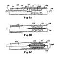
- FIGS. 6A-6Care partial sectional views depicting the embodiment of FIG. 1 in a first mode of operation
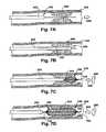
- FIGS. 7A-7Dare partial sectional views depicting the embodiment of FIG. 1 in a second mode of operation.
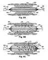
- FIGS. 8A-8Eare partial sectional views depicting a mechanism of operation of any embodiment of the present invention.
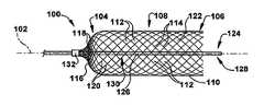
- FIG. 1depicts a first arrangement of an expandable member 100 for increasing blood flow through an obstructed blood vessel.
- the expandable member 100defines a longitudinal axis 102 , which may be rectilinear or curvilinear.
- the expandable member 100has a proximal member end 104 longitudinally spaced from a distal member end 106 .
- proximal and distalrefer to orientations inside a patient's body with respect to a user, with a proximal location being nearer to an insertion point into the body than a distal location.
- proximal and distalare used herein for ease of description without limiting the present invention.
- At least one of the proximal and distal member ends 104 and 106is closed, with a closed end, depicted as the proximal member end in FIG. 1 , being positioned further downstream in a blood vessel than the rest of the expandable member 100 .
- the expandable member 100is selectively moveable between a first, collapsed condition and a second, expanded condition.
- a tubular member body 108extends between the proximal and distal member ends 104 and 106 .
- the member body 108is adapted to selectively contact at least a portion of an obstruction within a blood vessel in a radial direction, the radial direction being defined with respect to the longitudinal axis 102 , and may exert a compressive force upon the obstruction.
- the member body 108is also adapted to dislodge at least one fragment from the obstruction and to enhance blood flow through the blood vessel past the obstruction, with these functions being described in further detail below.
- the member body 108is made of a first mesh 110 having a plurality of first interstices 112 .
- Each of the first interstices 112is defined by a plurality of first strands 114 .
- At least one of the first interstices 112is adapted to allow passage of at least one fragment therethrough in a radial direction into the member body 108 .
- a closed one of the proximal and distal member ends 104 and 106(as shown in FIG. 1 , the proximal member end) is made of a second mesh 116 having a plurality of second interstices 118 .
- Each of the second interstices 118is defined by a plurality of second strands 120 .
- At least one of the second interstices 118is adapted to selectively allow passage of at least one fragment therethrough.
- Many of the first and second interstices 112 and 118 and first and second strands 114 and 120are left unlabeled in the Figures for clarity of depiction.
- the first interstices 112are depicted in certain of the Figures as being larger than the second interstices 118 when there is an optional size difference between the two, the second interstices could instead be larger than the first interstices.
- the sizes of the first interstices 112could vary from one another and the sizes of the second interstices 118 need not be uniform either. It is contemplated that there could even be an overlap in size ranges between the first and second interstices 112 and 118 .
- first and second strands 114 and 120may be oriented in at least one of a helical, longitudinal, and radial direction with respect to the member body 108 .
- the first and second strands 114 and 120may each be formed of any desired material or combination of materials, including, but not limited to, a metal, an alloy, a composite, a polymer, and the like.
- the first and second strands 114 and 120may each be made of nitinol, stainless steel, cobalt chromium, platinum, titanium, plastic, or any combination thereof.
- the first and second strands 114 and 120may each have a diameter between about 10-250 microns, e.g., about 50 microns.
- any of the first and second strands 114 and 120may have a cross-sectional shape along at least a portion thereof which is designed to augment the performance of the expandable member 100 as described below.
- the cross-sectional shapemay include an angle designed to concentrate outward force of the expandable member at a specific portion of the strand cross-section periphery.
- at least a portion of any of the first and second strands 114 and 120could be coated with a material designed to produce a desired mechanical effect (e.g., cushioning, erosion, or any other effect) upon a surface contacted by the coated portion of the strand.
- the first and second meshes 110 and 116may be formed integrally or may be separately formed and attached together during manufacture of the expandable member 100 .
- the first and second meshes 110 and 114may each be at least partially constructed of a shape-memory material, such as nitinol.
- the first and second meshes 110 and 114may be formed in any desired manner, including, but not limited to, braiding, welding, molding, weaving, laser-cutting a tube or sheet, and the like.
- the first and second meshes 110 and 114should be configured for desired deployment characteristics, as described below, and to provide sufficient flexibility for tracking through a possibly tortuous vascular system of an individual, such as the intracranial vascular system.
- the closed distal member end 106is depicted in the Figures as having a tapered shape, the closed one (or both) of the proximal and distal member ends 104 and 106 can be of any suitable shape, such as, but not limited to, tubular, conical, convex, concave, or any other shape. Both of the proximal and distal member ends 104 and 106 , when closed, may be made from the first mesh 110 , the second mesh 116 , or any other mesh (not shown) and need not be made from the same mesh. The below description will presume that each closed end is made from the second mesh 116 .
- the shape of the closed one of the proximal and distal member ends 104 and 106may be coincidentally produced by the method used to form the closed end(s) or may be formed intentionally for a desired performance effect.
- the member body 108defines a body interior 122 .
- the expandable member 100may include a guidewire 124 extending longitudinally between the proximal and distal member ends 104 and 106 through the body interior 122 .
- the guidewire 124may have an operative length 126 between the proximal and distal member ends 104 and 106 of between about 0.5-50 mm, e.g., about 22 mm.
- the guidewire 124has a proximal guidewire end (not shown) longitudinally separated from a distal guidewire end 128 by a guidewire body 130 .
- the operative length 126 of the guidewire 124between the proximal and distal member ends 104 and 106 , is located adjacent the distal guidewire end 128 .
- the guidewire 124may help push or pull the expandable member 100 through the vascular system to a desired deployment location.
- any suitable portion of the expandable member 100may be attached to the guidewire 124 in a permanent manner (e.g., welding, crimping, soldering, adhesives, or the like) or by a temporary, releasable connection. If the latter, the connection mechanism (not shown) should be designed to be selectively releasable by the user as discussed below.
- the guidewire body 130has a length sufficient to extend through the vascular system to place the expandable member 100 in the desired deployment location.
- the guidewire body 130when the guidewire 124 is longitudinally connected to another structure (not shown) for moving the expandable member 100 , the guidewire body 130 will be shorter than if the guidewire is the only structure that moves the expandable member.
- the guidewire body 130may have a length of between about 0.5 mm-200 cm, e.g., about 150 cm.
- the diameter of the guidewire body 130may vary along the length of the guidewire body or may be constant.
- the diameter of the guidewire body 130 toward the proximal guidewire endmay be between about 0.2-1 mm, e.g., about 0.36 mm, while the diameter of the operative length 126 portion of the guidewire body may be between about 0.05-1 mm, e.g., about 0.15 mm.
- the proximal member end 104will be described below as being attached to the guidewire at or adjacent the distal guidewire end 128 , unless otherwise specifically indicated.
- the guidewire 124may extend beyond at least one of the proximal and distal member ends 104 and 106 to support the expandable member 100 , and may be adapted to removably or permanently attach the expandable member to a delivery system (not shown).
- the guidewire 124when affixed, can facilitate minor changes in the position of the expandable member 100 during use and also can increase positional stability of the expandable member.
- the expandable member 100may include at least one radiopaque portion, such as the attachment collar 132 shown in FIG. 1 , to facilitate remote visualization using, for example, one or more of fluoroscopy, computer tomography (CT) fluoroscopy, magnetic resonance, or the like.
- the radiopaque portioncould be a structure of the expandable member 100 made of a radiopaque material or could be a separate radiopaque marker/material attached to or coated on at least a portion of the expandable member. For example, a thin layer of platinum could be sprayed, electroplated, or otherwise coated onto at least a portion of the expandable member 100 .
- the expandable member 100may be at least partially adapted to elute a pharmaceutical agent (not shown).
- elutingmeans releasing, leaching, diffusing, or otherwise providing a pharmaceutical agent to a target area.
- the pharmaceutical agentmay be impregnated in or coated on at least a portion of the expandable member 100 , provided through a fluid connection between the expandable member and a pharmaceutical source (not shown), or otherwise directed to the target area via the expandable member 100 .
- a pharmaceutical agentmay be provided to the patient locally or systemically in any desired dosage, using a mechanism other than the expandable member 100 .
- thrombolytic medicationexamples include thrombolytic medication, anti-platelet medication, anti-thrombotic medication, a plasminogen activator (e.g., tPA, urokinase, streptokinase, desmotoplase), a IIb/IIIa inhibitor (e.g., abiciximab, tirofiban, eptifatide), a thrombin inhibitor (e.g., heparin, bivalirudin), or any combinations thereof.
- a plasminogen activatore.g., tPA, urokinase, streptokinase, desmotoplase
- IIb/IIIa inhibitore.g., abiciximab, tirofiban, eptifatide
- a thrombin inhibitore.g., heparin, bivalirudin
- FIG. 2depicts a second embodiment of an expandable member 100 b according to the present invention.
- the expandable member 100 b of FIG. 2is similar to the expandable member 100 of FIG. 1 and therefore, structures of FIG. 2 that are the same as or similar to those described with reference to FIG. 1 have the same reference numbers with the addition of a “b”. Description of common elements and operation similar to those in the previously described embodiment will not be repeated with respect to the second embodiment.
- the first and second meshes 110 b and 116 b of the second embodimentmay be formed integrally or may be separately provided and attached before use. As shown in FIG. 2 , however, at least one of the plurality of second interstices 118 b may be smaller than at least one of the plurality of first interstices 112 b.
- FIG. 3depicts a third embodiment of an expandable member 100 c according to the present invention.
- the expandable member 100 c of FIG. 3is similar to the expandable member 100 of FIG. 1 and therefore, structures of FIG. 3 that are the same as or similar to those described with reference to FIG. 1 have the same reference numbers with the addition of a “c”. Description of common elements and operation similar to those in the previously described embodiments will not be repeated with respect to the third embodiment.
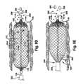
- both the proximal and distal ends 104 c and 106 care closed. Additionally, the proximal and distal ends 104 c and 106 c are both shown as being connected to the guidewire 124 c through attachment collars 132 c . Either or both of the attachment collars 132 c depicted in FIG. 3 , or any other portions of the expandable member 100 c , may be radiopaque.
- FIG. 4depicts a fourth embodiment of an expandable member 100 d according to the present invention.
- the expandable member 100 d of FIG. 4is similar to the expandable member 100 of FIG. 1 and therefore, structures of FIG. 4 that are the same as or similar to those described with reference to FIG. 1 have the same reference numbers with the addition of a “d”. Description of common elements and operation similar to those in the previously described embodiments will not be repeated with respect to the fourth embodiment.
- the fourth embodimentincludes first interstices 112 d which are a different size than the second interstices 118 d .
- the expandable member 100 d shown in FIG. 4omits the previously described guidewire.
- one of ordinary skill in the artcan readily design a suitable deployment mechanism for an expandable member 100 d lacking a guidewire, and the description of operation of the present invention (below) will presume that a guidewire is present, notwithstanding the depiction of FIG. 4 .
- FIG. 5depicts a fifth embodiment of an expandable member 100 e according to the present invention.
- the expandable member 100 e of FIG. 5is similar to the expandable member 100 of FIG. 1 and therefore, structures of FIG. 5 that are the same as or similar to those described with reference to FIG. 1 have the same reference numbers with the addition of a “e”. Description of common elements and operation similar to those in the previously described embodiment will not be repeated with respect to the fifth embodiment.
- FIG. 5illustrates an expandable member 100 e similar to that of the third embodiment, in which both the proximal and distal ends 104 e and 106 e are closed. Additionally, the proximal and distal ends 104 e and 106 e are both shown as being connected to the guidewire 124 e through attachment collars 132 e .
- the proximal end 104 eis not made of a tightly woven mesh, however, but instead includes a small number of second strands 120 e (four shown) linking the member body 108 e to the attachment collar 132 e.
- FIGS. 6A-6C and 7 A- 7 Ddepict first and second modes of operation, respectively, of the deployment of an expandable member 100 according to the present invention.
- the expandable member 100is described in a vascular application, the present invention may readily be used in other body lumens, as will be appreciated by one of ordinary skill in the art.
- a delivery catheter 232may be inserted into a blood vessel 234 in any suitable manner, such as through the use of endovascular, percutaneous, or other minimally invasive surgical techniques.
- the delivery catheter 232defines a longitudinal axis 236 , which may be rectilinear or curvilinear.
- the delivery catheter 232has proximal and distal catheter ends 238 and 240 , respectively, separated by a hollow catheter lumen 242 .
- the distal catheter end 240is adapted for placement within the blood vessel 234 adjacent an obstruction 244 , as shown in FIG. 6A .
- a nonlimiting example of a suitable delivery catheteris one of the Excelsior line of microcatheters, available from Boston Scientific of Natick, Mass.
- the 1.5-3 French sized Excelsior microcathetersfor example, may be useful in an intracranial application of the present invention.
- the obstruction 244may include any material that fully or partially blocks a blood vessel 234 , such as a thrombus.
- the thrombuscan arise due to conditions such as a cardioembolism, a carotid bifurcation, or an iatrogenic cause of idiopathic or cryptogenic etiology. Plaque, clots, grumous material, and/or other unwanted matter could also or instead form the obstruction 244 .
- Several of the Figuresare partial side or sectional views depicting the obstruction 244 in cross-section as a cylindrical obstruction lining the blood vessel 234 , but discontinuous patches of obstruction could also or instead be present.
- the obstruction 244may not be tightly adhered to the blood vessel 234 , but may be loosely held in position within the blood vessel, or could even be floating freely in the body. In the latter two cases, the expandable member 100 can be used to trap the obstruction 244 against a wall of the blood vessel 234 .
- the blood vessel 234may be of the intracranial cerebrovasculature, such as an internal carotid artery, a middle cerebral artery, an anterior cerebral artery, a vertebral basilar artery, or a posterior cerebral artery, or may be in any other body lumen or vessel.
- proximal and distalare used herein for clarity of description and do not limit the positioning or arrangement of the structures of the present invention.
- blood within the vesselflows in a bloodstream 246 direction, from the proximal catheter end 238 toward the distal catheter end 240 , and the obstruction 244 is accessed from upstream.
- the bloodstream 246may assist the operation of the expandable member 100
- one of ordinary skill in the artcan readily design a suitable expandable member and corresponding deployment apparatus which may be used in the opposite instance, when the obstruction 244 is accessed from downstream (not shown).
- the expandable member 100in dashed line, is in the first, collapsed condition within the catheter lumen 242 .
- the expandable member 100is attached to the guidewire 124 , which is adapted for selective insertion through the catheter lumen 242 .
- the guidewire 124travels through the catheter lumen 242 , the expandable member 100 is carried to the obstruction 244 .
- At least one of the delivery catheter 232 , guidewire 124 , and expandable member 100may include at least one radiopaque portion/marker (not shown) to aid the user in visualizing the position of the marked structure throughout the deployment procedure.
- the expandable member 100is still in the collapsed condition, but has exited the distal catheter end 240 and is located adjacent the obstruction 244 .
- the site of deployment of all or a portion of the expandable member 100is typically radially within the obstruction 244 .
- the site of deploymentcan also be upstream or downstream of the obstruction 244 , with the expandable member 100 being moved, in a collapsed or partially expanded condition, to a position radially within the obstruction.
- the obstruction 244need not entirely radially surround the expandable member 100 ; instead, the expandable member could be deployed radially off-center with respect to the obstruction, or the obstruction 244 may not entirely cover the inner circumference of the blood vessel 234 .
- the diameter of the expandable member 100may be between about 0.05-5 mm, e.g., about 0.016 mm, in the collapsed state and between about 0.1-10 mm, e.g., about 5 mm, in the expanded state.
- the length of the expandable member 100may be between about 5-60 mm, e.g., about 22 mm, in both the collapsed and expanded states, unless the design structure of the expandable member causes appreciable length change during radial expansion and collapse.
- the dimensions of the expandable member 100are highly dependent upon the dimensions of the delivery catheter and body lumen in which the expandable member 100 travels and is deployed, respectively, and one of ordinary skill in the art can readily choose appropriate dimensions for all structures used in a particular application of the present invention.
- the expandable member 100is shown in the second, expanded condition within at least a portion of the obstruction 244 .
- the arrow depicting the expansion direction 248indicates that a radially outward force is exerted by the expandable member 100 against the adjacent obstruction 244 .
- the expansion direction 248is shown as being two-dimensional, the expandable member 100 will expand radially in all directions outward from the longitudinal axis 102 unless the expandable member has been designed/configured for nonuniform expansion.
- the expandable member 100exits the delivery catheter 232 in the collapsed condition and is placed in the desired position adjacent the obstruction 244 before being expanded into the expanded condition.
- the expandable member 100 shown in FIGS. 6A-6Cmay self-expand once in position, for example, through use of a temperature-respondent shape-memory alloy.
- the expandable member 100may be manually expanded through use of an inflation balloon (not shown), in a known manner. That is, an inflation catheter (not shown) carrying the inflation balloon may be provided for selective insertion through the catheter lumen 242 .
- the expandable member 100is optionally crimped around the inflation balloon when in the collapsed condition.
- the inflation cathetermay replace the guidewire 124 in performing the function of guiding and/or carrying the expandable member 100 to the site of the obstruction 244 .
- the inflation catheterthrough the inflation balloon, then may be operative to selectively manually expand the expandable member 100 adjacent at least a portion of the obstruction 244 .
- the inflation balloonmay be configured so as not to block the first interstices 112 while the inflation balloon still exerts radially outward pressure on the expandable member, to help provide compression and fragmentation of the obstruction 244 as described below.
- a second mode of operation of the expandable member 100is depicted.
- a delivery catheter 232is advanced downstream through a blood vessel 234 to a position adjacent an obstruction 244 .
- the expandable member 100is at least partially constructed of a superelastic and/or self-expanding material, such as nitinol which has been memory-shaped into an expanded condition and is compressed into a collapsed condition before use. Therefore, the expandable member 100 is constrained in the collapsed condition by the delivery catheter 232 and self-expands into the expanded condition upon removal from the delivery catheter.
- FIG. 7Adepicts the delivery catheter 232 with the guidewire 124 extending from the distal catheter end 240 and through the obstruction 244 .
- FIG. 7Bthe delivery catheter 232 has been advanced over the guidewire 124 until the distal catheter end 240 is located radially adjacent at least a portion of the obstruction 244 .
- the expandable member 100shown in dashed line in FIG. 7B within the delivery catheter 232 , is also located radially adjacent at least a portion of the obstruction 244 .
- a secondary guidewire(not shown) may be provided to assist in positioning the delivery catheter; the secondary guidewire could then be exchanged for the guidewire 124 for deployment of the expandable member.
- the expandable member 100is maintained in position within the obstruction 244 while the delivery catheter 232 is withdrawn in a proximal direction from the expandable member, thus exposing the distal member end 106 . Because the expandable member 100 in the second mode of operation is self-expanding, the distal member end 106 begins to expand in a known manner in the expansion direction 248 as the expandable member is released by the delivery catheter 232 .
- FIG. 7Ddepicts the self-expanding expandable member 100 of the second mode of operation in a fully expanded condition adjacent the obstruction 244 . Since the bloodflow direction 246 in the orientation of FIGS. 7A-7D moves proximal-to-distal, it is desirable for the distal member end 106 to be closed and to be located downstream of the proximal member end 104 , which is also shown in FIGS. 7A-7D as being closed. As can be seen in FIG. 7D , the proximal and distal member ends 104 and 106 may be connected to the guidewire 124 by the attachment collars 132 .
- the obstruction 244becomes at least partially compressed against the blood vessel 234 as the expandable member 100 expands, regardless of the means by which such expansion occurs. This compression aids in increasing blood flow past the obstruction 244 .
- the sequence of FIGS. 8A-8Edepicts both this compression and a separate erosion-type process as a combined mechanism of operation through which any embodiment of the present invention increases blood flow through the obstructed blood vessel 234 .
- the expandable member 100is positioned adjacent the obstruction 244 with the proximal member end 104 located upstream of the distal member end 106 (both shown here as being closed).
- the bloodflow direction 246is from left to right, in the orientation of FIGS. 8A-8E , and the expandable member 100 is exerting outward radial force in the expansion direction 248 .
- the force exerted by the expandable member 100depends on a number of factors, which include the properties of the material chosen for the expandable member. By suitably varying these factors, the force exerted by the expandable member 100 can be controlled.
- the expandable member 100may exert sufficient force to cause the member body 108 , or another portion of the expandable member, to compress at least a portion of the obstruction 244 against a vessel wall 350 of the blood vessel 234 .
- the force exerted by the expandable member 100dislodges at least one fragment 352 from the obstruction 244 and helps pass each fragment 352 through a first interstice 112 in the radial direction into the body interior 122 .
- at least one of the plurality of first strands 114may penetrate into the obstruction 244 to longitudinally separate each fragment 352 from a remaining portion of the obstruction.
- the action by which the expandable member 100 dislodges the fragments 352may vary depending upon the composition of the obstruction 244 .
- the first strands 114may slice radially into the obstruction 244 and the fragments 352 will protrude into the expandable member 100 in an extruding manner.
- pressure from the first strands 114may instead flake off fragments 352 in a fracturing manner.
- the expandable member 100may be adapted for at least a small degree of rotation about the longitudinal axis 102 . Such rotation, once the first strands 114 are at least partially embedded in the obstruction 244 , may help to free the fragments 352 from the obstruction 244 by severance in a circumferential direction about the longitudinal axis 102 .
- the expandable member 100Whether or not the expandable member 100 is rotated, blood flowing in the bloodflow direction 246 will exert pressure on the fragments 352 to help separate the fragments from the obstruction 244 .
- the fragments 352once free within the member body 108 , are then carried by the blood in the bloodflow direction 246 toward the (closed) distal member end 106 , where the fragments collect as shown in FIG. 8C .
- the size of at least one of the plurality of first interstices 112 and/or the plurality of second interstices 118may be chosen depending upon an allowable particulate size of the blood vessel 234 .
- This allowable particulate sizemay vary, depending upon the size and location of the blood vessel 234 , the size and location of other vasculature in fluid connection downstream from the blood vessel 234 , the presence of any pharmaceutical agents and/or other medical devices within the blood vessel 234 , or any other factors.
- the size of fragment 352 which may pass through the first and second interstices 112 and 118will vary depending upon at least the position of that interstice on the member body 108 , the degree of expansion of the expandable member 100 , the shape of the fragment 352 , and the orientation of the interstice with respect to the bloodflow direction 246 . For example, if a certain interstice (particularly a second interstice 118 ) is oriented substantially perpendicularly to the longitudinal axis 108 , a larger fragment 352 may more readily pass through that interstice than if the interstice were at an oblique angle with respect to the longitudinal axis.
- first and second meshes 110 and 116having desired properties to selectively retain the fragments 352 in a suitable manner for a particular application of the present invention.
- At least one of the plurality of second strands 120may break the fragment into a plurality of subfragments 354 .
- At least one of the second interstices 118may then allow passage therethrough of at least one subfragment 354 to release the subfragment 354 from the expandable member 100 .
- the second strand 120breaks the fragment 352 into subfragments 354 in a similar manner to that in which the first strand 114 dislodges the fragment from the obstruction 244 .
- the fragments 352could also undergo chemical lysing to enhance the breakup of the obstruction 244 .
- a pharmaceutical agent(not shown) could be provided to at least partially lyse at least one fragment 352 and/or subfragment 354 .
- the pharmaceutical agentmay be eluted by the expandable member 100 , as previously mentioned. Additionally or alternatively, the pharmaceutical agent may be provided via the delivery catheter 232 at a location adjacent the obstruction 244 . Moreover, the pharmaceutical agent could be locally or systemically provided to the patient in another manner.
- chemical lysingwill be operative upon at least one of the obstruction 244 , a fragment 352 , and/or a subfragment 354 .
- Chemical lysing agentsare most effective upon structures having a large ratio of surface area to volume, so it is advantageous to mechanically break up the obstruction 244 into smaller pieces (such as fragments 352 and/or subfragments 354 ) to decrease the time required for the obstruction 244 to chemically lyse.
- the expandable member 100continues to exert pressure upon the obstruction 244 in the expansion direction 248 as fragments 352 are dislodged from the obstruction. Therefore, as the volume of the obstruction 244 is reduced by loss of the fragments 352 and/or by compression of the obstruction 244 toward the vessel wall 350 , more blood will be able to flow through the volume-diminished obstruction 244 . The increased bloodflow past the obstruction 244 will help to mechanically lyse the obstruction, whether or not the expandable member 100 continues to dislodge fragments 352 from the obstruction. Stasis (e.g., that caused by an obstruction 244 ) in a blood vessel 234 allows for factors which promote obstructions to accumulate, thereby maintaining the obstruction in the blood vessel.
- Stasise.g., that caused by an obstruction 244
- an aspiration catheter(not shown) is adapted for selective insertion through the catheter lumen 242 .
- the aspiration catheterwhen present, is operative to selectively remove at least one fragment 352 from the expandable member 100 under suction power.
- the aspiration cathetermay place the body interior 122 into direct fluid communication with a suction source (not shown) to directly remove the fragment 352 from within the expandable member 100 .
- the aspiration cathetermay exert suction power upon the fragment 352 from an outside position adjacent the proximal or distal member ends 104 or 106 to supplement the pressure naturally provided in the bloodflow direction 246 and thereby pull the fragment through a second interstice 118 , either into the aspiration catheter for removal from the body or to enhance release of the fragment into the blood vessel 234 downstream of the expansion member 100 .
- the use of such an aspiration cathetermay be desirable if fragments 352 collecting at the distal member end 106 are not exiting the expandable member 100 and are reducing bloodflow through the expandable member in an unwanted manner.
- the expandable member 100may be collapsed from the expanded condition to the collapsed condition and removed from the blood vessel 234 through the delivery catheter 232 .
- FIG. 8Edepicts the expandable member 100 in the process of collapsing.
- the expandable member 100is maintained in position inside the blood vessel 234 , and the delivery catheter is moved in a sheathing direction 356 (opposite the bloodflow direction 246 ) to envelop the expandable member.
- the expandable member 100will be constrained into the collapsed condition upon contact with the distal catheter end 240 and can then be held within the catheter lumen 242 for removal from the blood vessel 234 .
- the delivery catheter 232could be maintained in position so that the guidewire 124 can be pulled in the bloodflow direction 246 .
- the guidewire in this alternate removal modethus pulls an attached expandable member 100 into a relatively stationary delivery catheter.
- the delivery catheter 232 and the expandable member 100can both or either move to produce a relative sheathing motion between these two structures.
- the expandable member 100can be collapsed from the expanded condition into the collapsed condition in any suitable manner, and then moved rotationally and/or longitudinally within the blood vessel 234 while constrained, such as through a motion of the delivery catheter 232 enclosing the expandable member.
- the expandable member 100once positioned as desired, may then be re-expanded from the collapsed condition to the expanded condition.
- redeploymentmay be useful, for example, when the obstruction 244 has a longitudinal dimension greater than that of the expandable member 100 or when the same expandable member is operative on a plurality of spaced-apart obstructions 244 .
- the expandable member 100may be collapsed and redeployed any number of times, as desired by the user.
- angiographycan be performed to assess blood flow, with additional mechanical and/or chemical lysing being performed until the blood flow has achieved a suitable rate for a predetermined period of time—for example, between about 10-15 minutes.
- acute and chronic anti-platelet therapyis no longer necessary to prevent the expandable member from causing future obstructions.
- Such acute and chronic anti-platelet therapymay increase the likelihood of development of complication, such as an intracranial hemorrhage, associated with other methods of acute revascularization.
- An intracranial hemorrhage occurring when the patient's system contains pharmaceutical agents for chemical lysingmay be fatal.
- surgical treatment for an intracranial hemorrhageis fraught with postoperative complications. Therefore, it may be desirable for the expandable member 100 to be removed from the patient's body.
- the expandable member 100may be removed from the blood vessel 234 before the structures of the expandable member heal into the vessel wall 350 .
- the expandable member 100may be removed in the above manner from about one (1) minute to about 48 hours after delivery of the device, with re-operation possibly being required for removal toward the latter portion of that range of time.
- the expandable member 100should be adapted for release from the guidewire 124 , preferably when the expandable member is in the expanded condition at the desired implantation location within the blood vessel 234 .
- the releasemay be carried out in any suitable manner, using any desired mechanical, chemical, electrolytic, temperature-sensitive, remotely-triggered, or other type of release means.
- At least one fragment 352may be carried from the blood vessel 234 within the expandable member 100 as the expandable member is withdrawn through the delivery catheter 232 . Additionally, the force exerted by the distal catheter end 240 on the expandable member 100 may squeeze the fragments 352 collected at the distal member end 106 against the first or second strands 114 or 120 . Such squeezing force may cause extrusion or flaking of the fragments into subfragments 354 , which are then released into the blood vessel 234 as shown in FIG. 8E .
- the first and second meshes 110 and 116should be designed such that these delayed subfragments 354 do not exceed the allowable particulate size of the blood vessel 234 .
- the member body 108could have a round, ovoid, rectilinear, curvilinear, or any other desired cross-sectional shape.
- the expandable member 100can expand or collapse in a radial, circumferential, and/or longitudinal direction. Like all described structures, the expandable member 100 may be made of any materials and in any dimensions, as appropriate for a particular application of the present invention.
- the expanded and collapsed conditions of the expandable member 100are not strict binary limits upon the condition of the expandable member, but represent more general ranges of condition (e.g., an expandable member in the “expanded” condition may be able to expand further as the obstruction 244 is eroded and/or compressed).
- first strands 114may perform functions of the second strands 120 and vice versa, particularly if the divisions between the member body 108 and proximal/distal member ends 104 and 106 are not sharply delineated.
- certain strandsmay function as both first and second strands 114 and 120 at various points along the length thereof.
- the expandable member 100can be used in conjunction with lytic agents (tPA and IIb/IIIa inhibitors), and can also be used with various microcatheters, guidewires and endovascular access devices that are currently commercially available. Operation of the expandable member 100 is described as being assisted by bloodflow within the blood vessel 234 , but the present invention is also operable when bloodflow is intentionally or inadvertently reduced or eliminated within the blood vessel 234 .
- the expandable member 100is described as performing a filtering function upon fragments 352 dislodged from the obstruction 244 , but could also or instead provide a filtering function to existing fragments (not shown) in the bloodstream which did not originate with the obstruction. A device or method incorporating any of these features should be understood to fall under the scope of the present invention as determined based upon the claims below and any equivalents thereof.
Landscapes
- Health & Medical Sciences (AREA)
- Life Sciences & Earth Sciences (AREA)
- Heart & Thoracic Surgery (AREA)
- Public Health (AREA)
- Veterinary Medicine (AREA)
- Engineering & Computer Science (AREA)
- Biomedical Technology (AREA)
- Animal Behavior & Ethology (AREA)
- General Health & Medical Sciences (AREA)
- Surgery (AREA)
- Hematology (AREA)
- Anesthesiology (AREA)
- Vascular Medicine (AREA)
- Pulmonology (AREA)
- Child & Adolescent Psychology (AREA)
- Biophysics (AREA)
- Molecular Biology (AREA)
- Medical Informatics (AREA)
- Nuclear Medicine, Radiotherapy & Molecular Imaging (AREA)
- Orthopedic Medicine & Surgery (AREA)
- Surgical Instruments (AREA)
- Media Introduction/Drainage Providing Device (AREA)
- Prostheses (AREA)
- External Artificial Organs (AREA)
Abstract
Description
Claims (15)
Priority Applications (6)
| Application Number | Priority Date | Filing Date | Title |
|---|---|---|---|
| US13/184,359US8317748B2 (en) | 2006-02-01 | 2011-07-15 | Method and apparatus for increasing blood flow through an obstructed blood vessel |
| US13/672,496US10201359B2 (en) | 2006-02-01 | 2012-11-08 | Method and apparatus for increasing blood flow through an obstructed blood vessel |
| US13/672,445US8696622B2 (en) | 2006-02-01 | 2012-11-08 | Method and apparatus for increasing blood flow through an obstructed blood vessel |
| US13/672,323US8702652B2 (en) | 2006-02-01 | 2012-11-08 | Method and apparatus for increasing blood flow through an obstructed blood vessel |
| US16/225,691US20190125374A1 (en) | 2006-02-01 | 2018-12-19 | Method and apparatus for increasing blood flow through an obstructed blood vessel |
| US16/262,484US11090070B2 (en) | 2006-02-01 | 2019-01-30 | Method and apparatus for increasing blood flow through an obstructed blood vessel |
Applications Claiming Priority (4)
| Application Number | Priority Date | Filing Date | Title |
|---|---|---|---|
| US76420606P | 2006-02-01 | 2006-02-01 | |
| US79358806P | 2006-04-20 | 2006-04-20 | |
| US11/700,987US8052640B2 (en) | 2006-02-01 | 2007-02-01 | Method and apparatus for increasing blood flow through an obstructed blood vessel |
| US13/184,359US8317748B2 (en) | 2006-02-01 | 2011-07-15 | Method and apparatus for increasing blood flow through an obstructed blood vessel |
Related Parent Applications (1)
| Application Number | Title | Priority Date | Filing Date |
|---|---|---|---|
| US11/700,987DivisionUS8052640B2 (en) | 2006-02-01 | 2007-02-01 | Method and apparatus for increasing blood flow through an obstructed blood vessel |
Related Child Applications (3)
| Application Number | Title | Priority Date | Filing Date |
|---|---|---|---|
| US13/672,496DivisionUS10201359B2 (en) | 2006-02-01 | 2012-11-08 | Method and apparatus for increasing blood flow through an obstructed blood vessel |
| US13/672,323DivisionUS8702652B2 (en) | 2006-02-01 | 2012-11-08 | Method and apparatus for increasing blood flow through an obstructed blood vessel |
| US13/672,445DivisionUS8696622B2 (en) | 2006-02-01 | 2012-11-08 | Method and apparatus for increasing blood flow through an obstructed blood vessel |
Publications (2)
| Publication Number | Publication Date |
|---|---|
| US20110270178A1 US20110270178A1 (en) | 2011-11-03 |
| US8317748B2true US8317748B2 (en) | 2012-11-27 |
Family
ID=38266663
Family Applications (9)
| Application Number | Title | Priority Date | Filing Date |
|---|---|---|---|
| US11/700,987Active2030-06-12US8052640B2 (en) | 2006-02-01 | 2007-02-01 | Method and apparatus for increasing blood flow through an obstructed blood vessel |
| US13/184,359ActiveUS8317748B2 (en) | 2006-02-01 | 2011-07-15 | Method and apparatus for increasing blood flow through an obstructed blood vessel |
| US13/281,068ActiveUS8366663B2 (en) | 2006-02-01 | 2011-10-25 | Method and apparatus for increasing blood flow through an obstructed blood vessel |
| US13/672,323Expired - LifetimeUS8702652B2 (en) | 2006-02-01 | 2012-11-08 | Method and apparatus for increasing blood flow through an obstructed blood vessel |
| US13/672,445ActiveUS8696622B2 (en) | 2006-02-01 | 2012-11-08 | Method and apparatus for increasing blood flow through an obstructed blood vessel |
| US13/672,496Active2031-03-19US10201359B2 (en) | 2006-02-01 | 2012-11-08 | Method and apparatus for increasing blood flow through an obstructed blood vessel |
| US13/747,757AbandonedUS20130131703A1 (en) | 2006-02-01 | 2013-01-23 | Method and apparatus for increasing blood flow through an obstructed blood vessel |
| US16/225,691AbandonedUS20190125374A1 (en) | 2006-02-01 | 2018-12-19 | Method and apparatus for increasing blood flow through an obstructed blood vessel |
| US16/262,484Active2027-07-03US11090070B2 (en) | 2006-02-01 | 2019-01-30 | Method and apparatus for increasing blood flow through an obstructed blood vessel |
Family Applications Before (1)
| Application Number | Title | Priority Date | Filing Date |
|---|---|---|---|
| US11/700,987Active2030-06-12US8052640B2 (en) | 2006-02-01 | 2007-02-01 | Method and apparatus for increasing blood flow through an obstructed blood vessel |
Family Applications After (7)
| Application Number | Title | Priority Date | Filing Date |
|---|---|---|---|
| US13/281,068ActiveUS8366663B2 (en) | 2006-02-01 | 2011-10-25 | Method and apparatus for increasing blood flow through an obstructed blood vessel |
| US13/672,323Expired - LifetimeUS8702652B2 (en) | 2006-02-01 | 2012-11-08 | Method and apparatus for increasing blood flow through an obstructed blood vessel |
| US13/672,445ActiveUS8696622B2 (en) | 2006-02-01 | 2012-11-08 | Method and apparatus for increasing blood flow through an obstructed blood vessel |
| US13/672,496Active2031-03-19US10201359B2 (en) | 2006-02-01 | 2012-11-08 | Method and apparatus for increasing blood flow through an obstructed blood vessel |
| US13/747,757AbandonedUS20130131703A1 (en) | 2006-02-01 | 2013-01-23 | Method and apparatus for increasing blood flow through an obstructed blood vessel |
| US16/225,691AbandonedUS20190125374A1 (en) | 2006-02-01 | 2018-12-19 | Method and apparatus for increasing blood flow through an obstructed blood vessel |
| US16/262,484Active2027-07-03US11090070B2 (en) | 2006-02-01 | 2019-01-30 | Method and apparatus for increasing blood flow through an obstructed blood vessel |
Country Status (10)
| Country | Link |
|---|---|
| US (9) | US8052640B2 (en) |
| EP (1) | EP1981413B1 (en) |
| JP (1) | JP5164861B2 (en) |
| CN (1) | CN101400309B (en) |
| AU (1) | AU2007211269B2 (en) |
| BR (1) | BRPI0707681A2 (en) |
| CA (1) | CA2641249C (en) |
| ES (1) | ES2524778T3 (en) |
| MX (1) | MX2008009863A (en) |
| WO (1) | WO2007089897A2 (en) |
Cited By (27)
| Publication number | Priority date | Publication date | Assignee | Title |
|---|---|---|---|---|
| US20130066348A1 (en)* | 2006-02-01 | 2013-03-14 | The Cleveland Clinic Foundation | Method and apparatus for increasing blood flow through an obstructed blood vessel |
| US9526865B2 (en) | 2014-06-09 | 2016-12-27 | Inceptus Medical, Llc | Retraction and aspiration device for treating embolism and associated systems and methods |
| US9700332B2 (en) | 2015-10-23 | 2017-07-11 | Inari Medical, Inc. | Intravascular treatment of vascular occlusion and associated devices, systems, and methods |
| US9717519B2 (en) | 2012-11-20 | 2017-08-01 | Inceptus Medical, Llc | Methods and apparatus for treating embolism |
| US10045790B2 (en) | 2012-09-24 | 2018-08-14 | Inari Medical, Inc. | Device and method for treating vascular occlusion |
| US10098651B2 (en) | 2017-01-10 | 2018-10-16 | Inari Medical, Inc. | Devices and methods for treating vascular occlusion |
| US10238406B2 (en) | 2013-10-21 | 2019-03-26 | Inari Medical, Inc. | Methods and apparatus for treating embolism |
| US10342571B2 (en) | 2015-10-23 | 2019-07-09 | Inari Medical, Inc. | Intravascular treatment of vascular occlusion and associated devices, systems, and methods |
| US10687834B2 (en) | 2013-03-13 | 2020-06-23 | DePuy Synthes Products, Inc. | Ischemic stroke device |
| US11000682B2 (en) | 2017-09-06 | 2021-05-11 | Inari Medical, Inc. | Hemostasis valves and methods of use |
| US11013900B2 (en) | 2018-03-08 | 2021-05-25 | CereVasc, Inc. | Systems and methods for minimally invasive drug delivery to a subarachnoid space |
| US11154314B2 (en) | 2018-01-26 | 2021-10-26 | Inari Medical, Inc. | Single insertion delivery system for treating embolism and associated systems and methods |
| US11278708B2 (en) | 2014-01-15 | 2022-03-22 | Tufts Medical Center, Inc. | Endovascular cerebrospinal fluid shunt |
| US11383068B2 (en) | 2018-07-20 | 2022-07-12 | eLum Technologies, Inc. | Neurovascular distal access support catheters, aspiration catheters, or device shafts |
| US11399853B2 (en) | 2018-05-30 | 2022-08-02 | eLum Technologies, Inc. | Integrated thrombectomy and filter device and methods of use |
| US11433218B2 (en) | 2015-12-18 | 2022-09-06 | Inari Medical, Inc. | Catheter shaft and associated devices, systems, and methods |
| US11529158B2 (en) | 2004-03-25 | 2022-12-20 | Inari Medical, Inc. | Method for treating vascular occlusion |
| US11554005B2 (en) | 2018-08-13 | 2023-01-17 | Inari Medical, Inc. | System for treating embolism and associated devices and methods |
| US11679195B2 (en) | 2021-04-27 | 2023-06-20 | Contego Medical, Inc. | Thrombus aspiration system and methods for controlling blood loss |
| US11771875B2 (en) | 2017-03-02 | 2023-10-03 | CereVasc, Inc. | Catheter systems and methods for medical procedures using catheters |
| US20230310815A1 (en)* | 2022-04-05 | 2023-10-05 | The Board Of Trustees Of The University Of Illinois | Proximal ventriculoperitoneal shunt with retractable mesh |
| US11864779B2 (en) | 2019-10-16 | 2024-01-09 | Inari Medical, Inc. | Systems, devices, and methods for treating vascular occlusions |
| US11918243B2 (en) | 2015-10-23 | 2024-03-05 | Inari Medical, Inc. | Intravascular treatment of vascular occlusion and associated devices, systems, and methods |
| US11951270B2 (en) | 2015-10-30 | 2024-04-09 | Cerevasc, Llc | Systems and methods for endovascularly accessing a subarachnoid space |
| US12011557B2 (en) | 2014-10-31 | 2024-06-18 | CereVasc, Inc. | Methods and systems for draining cerebrospinal fluid into the venous system |
| US12036375B2 (en) | 2016-10-11 | 2024-07-16 | CereVasc, Inc. | Methods and systems for treating hydrocephalus |
| US12364496B2 (en) | 2022-01-11 | 2025-07-22 | Inari Medical, Inc. | Devices for removing clot material from intravascularly implanted devices, and associated systems and methods |
Families Citing this family (193)
| Publication number | Priority date | Publication date | Assignee | Title |
|---|---|---|---|---|
| US9498604B2 (en) | 1997-11-12 | 2016-11-22 | Genesis Technologies Llc | Medical device and method |
| DE10027401A1 (en)* | 2000-06-02 | 2001-12-20 | Emitec Emissionstechnologie | Device, for adsorbing one component of exhaust gas from vehicle engine, has adsorber with volume calculated by equation, through which exhaust gas is made to flow |
| DE10233085B4 (en) | 2002-07-19 | 2014-02-20 | Dendron Gmbh | Stent with guide wire |
| US8425549B2 (en) | 2002-07-23 | 2013-04-23 | Reverse Medical Corporation | Systems and methods for removing obstructive matter from body lumens and treating vascular defects |
| CA2565106C (en) | 2004-05-25 | 2013-11-05 | Chestnut Medical Technologies, Inc. | Flexible vascular occluding device |
| US8617234B2 (en) | 2004-05-25 | 2013-12-31 | Covidien Lp | Flexible vascular occluding device |
| CA2758946C (en) | 2004-05-25 | 2014-10-21 | Tyco Healthcare Group Lp | Vascular stenting for aneurysms |
| US8623067B2 (en) | 2004-05-25 | 2014-01-07 | Covidien Lp | Methods and apparatus for luminal stenting |
| US20060206200A1 (en) | 2004-05-25 | 2006-09-14 | Chestnut Medical Technologies, Inc. | Flexible vascular occluding device |
| AU2005332044B2 (en) | 2005-05-25 | 2012-01-19 | Covidien Lp | System and method for delivering and deploying and occluding device within a vessel |
| US20080114439A1 (en)* | 2005-06-28 | 2008-05-15 | Venkatesh Ramaiah | Non-occluding dilation device |
| EP1986568B1 (en) | 2006-02-03 | 2017-04-05 | Covidien LP | Methods and devices for restoring blood flow within blocked vasculature |
| US8152833B2 (en) | 2006-02-22 | 2012-04-10 | Tyco Healthcare Group Lp | Embolic protection systems having radiopaque filter mesh |
| US20080269774A1 (en) | 2006-10-26 | 2008-10-30 | Chestnut Medical Technologies, Inc. | Intracorporeal Grasping Device |
| US10076346B2 (en) | 2007-04-17 | 2018-09-18 | Covidien Lp | Complex wire formed devices |
| US7988646B2 (en)* | 2007-06-26 | 2011-08-02 | Mark Taber | Catheter apparatus and methods for treating vasculatures |
| US8100855B2 (en) | 2007-09-17 | 2012-01-24 | Abbott Cardiovascular Systems, Inc. | Methods and devices for eluting agents to a vessel |
| US9034007B2 (en) | 2007-09-21 | 2015-05-19 | Insera Therapeutics, Inc. | Distal embolic protection devices with a variable thickness microguidewire and methods for their use |
| US20100022951A1 (en)* | 2008-05-19 | 2010-01-28 | Luce, Forward, Hamilton 7 Scripps, Llp | Detachable hub/luer device and processes |
| US20100174309A1 (en)* | 2008-05-19 | 2010-07-08 | Mindframe, Inc. | Recanalization/revascularization and embolus addressing systems including expandable tip neuro-microcatheter |
| US8088140B2 (en) | 2008-05-19 | 2012-01-03 | Mindframe, Inc. | Blood flow restorative and embolus removal methods |
| US10123803B2 (en)* | 2007-10-17 | 2018-11-13 | Covidien Lp | Methods of managing neurovascular obstructions |
| US9220522B2 (en) | 2007-10-17 | 2015-12-29 | Covidien Lp | Embolus removal systems with baskets |
| US8066757B2 (en) | 2007-10-17 | 2011-11-29 | Mindframe, Inc. | Blood flow restoration and thrombus management methods |
| US8926680B2 (en) | 2007-11-12 | 2015-01-06 | Covidien Lp | Aneurysm neck bridging processes with revascularization systems methods and products thereby |
| US20100256600A1 (en)* | 2009-04-04 | 2010-10-07 | Ferrera David A | Neurovascular otw pta balloon catheter and delivery system |
| US11337714B2 (en) | 2007-10-17 | 2022-05-24 | Covidien Lp | Restoring blood flow and clot removal during acute ischemic stroke |
| US9198687B2 (en)* | 2007-10-17 | 2015-12-01 | Covidien Lp | Acute stroke revascularization/recanalization systems processes and products thereby |
| US8585713B2 (en) | 2007-10-17 | 2013-11-19 | Covidien Lp | Expandable tip assembly for thrombus management |
| JP2011507633A (en)* | 2007-12-19 | 2011-03-10 | マインドフレーム, インコーポレイテッド | Improved device and method for emboli removal during severe ischemic stroke |
| JP5457373B2 (en) | 2008-02-22 | 2014-04-02 | コヴィディエン リミテッド パートナーシップ | Device for blood flow recovery |
| US20090248059A1 (en)* | 2008-03-25 | 2009-10-01 | Hesham Morsi | Embolectomy Catheter |
| CN101977650A (en)* | 2008-04-11 | 2011-02-16 | 曼德弗雷姆公司 | Monorail neural microcatheter for delivery of medical device for treatment of stroke, methods and products thereof |
| US20090292307A1 (en)* | 2008-05-22 | 2009-11-26 | Nasser Razack | Mechanical embolectomy device and method |
| EP2341845B1 (en) | 2008-07-22 | 2016-01-06 | Neuravi Limited | Clot capture systems |
| US9402707B2 (en) | 2008-07-22 | 2016-08-02 | Neuravi Limited | Clot capture systems and associated methods |
| CA2732313A1 (en)* | 2008-07-30 | 2010-02-04 | Cornell University | Method and apparatus for straightening and flattening the side wall of a body lumen or body cavity so as to provide three dimensional exposure of a lesion or abnormality within the body lumen or body cavity, and/or for stabilizing an instrument relative to the same |
| US20100087850A1 (en)* | 2008-10-03 | 2010-04-08 | Nasser Razack | Mechanical Embolectomy Device and Method |
| US20100137899A1 (en)* | 2008-12-02 | 2010-06-03 | Nasser Razack | Mechanical Embolectomy Device and Method |
| WO2010075445A1 (en) | 2008-12-23 | 2010-07-01 | Silk Road Medical, Inc. | Methods and systems for treatment of acute ischemic stroke |
| US20100191168A1 (en) | 2009-01-29 | 2010-07-29 | Trustees Of Tufts College | Endovascular cerebrospinal fluid shunt |
| DE102009017050B4 (en)* | 2009-04-09 | 2016-09-01 | Acandis Gmbh & Co. Kg | Device for removing concrements from body vessels |
| JP2012525239A (en) | 2009-05-01 | 2012-10-22 | エンドロジックス、インク | Transcutaneous methods and devices for treating dissociation (priority information and incorporation by reference) |
| US10772717B2 (en) | 2009-05-01 | 2020-09-15 | Endologix, Inc. | Percutaneous method and device to treat dissections |
| US8784467B2 (en) | 2009-05-15 | 2014-07-22 | Lemaitre Vascular, Inc. | Non-occlusive dilation devices |
| TR201907891T4 (en) | 2009-06-15 | 2019-06-21 | Perflow Medical Ltd | Apparatus for maintaining blood flow through a blocked vein. |
| WO2011017123A2 (en) | 2009-07-27 | 2011-02-10 | Endologix, Inc. | Stent graft |
| US20110087254A1 (en)* | 2009-10-09 | 2011-04-14 | Cardiovascular Systems, Inc. | Rotational atherectomy device with keyed exchangeable drive shaft |
| DE102010025661A1 (en)* | 2010-02-05 | 2011-08-11 | Acandis GmbH & Co. KG, 76327 | Medical device for the release of concrements, method for producing such a device, treatment system with such a device and method for producing a treatment system |
| CA2804254C (en)* | 2010-02-23 | 2016-11-01 | Medina Medical, Inc. | Devices and methods for vascular recanalization |
| US20120046600A1 (en)* | 2010-02-25 | 2012-02-23 | Cardiovascular Systems, Inc. | High-speed rotational atherectomy system, device and method for localized application of therapeutic agents to a biological conduit |
| DE102010045367B4 (en)* | 2010-05-18 | 2019-08-08 | Acandis Gmbh | Medical device for removing concrements |
| US9561094B2 (en) | 2010-07-23 | 2017-02-07 | Nfinium Vascular Technologies, Llc | Devices and methods for treating venous diseases |
| US9039749B2 (en) | 2010-10-01 | 2015-05-26 | Covidien Lp | Methods and apparatuses for flow restoration and implanting members in the human body |
| ES2683943T3 (en) | 2010-10-22 | 2018-09-28 | Neuravi Limited | Clot capture and removal system |
| WO2012064726A1 (en) | 2010-11-12 | 2012-05-18 | Stryker Corporation | Axially variable radial pressure cages for clot capture |
| JP5944914B2 (en) | 2010-11-15 | 2016-07-05 | エンドバスキュラー ディベロップメント アクティエボラーグ | Assembly with guide wire and fixator for attachment to a blood vessel |
| US9393100B2 (en) | 2010-11-17 | 2016-07-19 | Endologix, Inc. | Devices and methods to treat vascular dissections |
| DE102010051740A1 (en)* | 2010-11-19 | 2012-05-24 | Phenox Gmbh | thrombectomy |
| WO2012081020A1 (en)* | 2010-12-12 | 2012-06-21 | Perflow Medical Ltd. | Method and apparatus for occlusion retrieval |
| DE102011011510B4 (en)* | 2011-02-17 | 2022-12-29 | Acandis Gmbh | Medical device for removing calculus and system with such a medical device |
| US12076037B2 (en) | 2011-03-09 | 2024-09-03 | Neuravi Limited | Systems and methods to restore perfusion to a vessel |
| EP4566553A3 (en) | 2011-03-09 | 2025-08-06 | Neuravi Limited | A clot retrieval device for removing occlusive clot from a blood vessel |
| US11259824B2 (en) | 2011-03-09 | 2022-03-01 | Neuravi Limited | Clot retrieval device for removing occlusive clot from a blood vessel |
| US10625069B2 (en)* | 2011-03-14 | 2020-04-21 | Cook Medical Technologies, LLC | Infusion system having filtration device and method |
| US9707374B2 (en)* | 2011-03-14 | 2017-07-18 | Cook Medical Technologies Llc | Infusion system having filtration device and method |
| EP4101399B1 (en) | 2011-08-05 | 2025-04-09 | Route 92 Medical, Inc. | System for treatment of acute ischemic stroke |
| US10779855B2 (en) | 2011-08-05 | 2020-09-22 | Route 92 Medical, Inc. | Methods and systems for treatment of acute ischemic stroke |
| WO2013023121A1 (en)* | 2011-08-11 | 2013-02-14 | Boston Scientific Scimed, Inc. | Expandable scaffold with cutting elements mounted thereto |
| DE102011120004B3 (en) | 2011-11-30 | 2013-03-14 | Universitätsklinikum Freiburg | Device for detaching wall-shaped thrombi from a body vessel |
| CN102488578B (en)* | 2011-12-14 | 2014-10-15 | 湖南瑞康通科技发展有限公司 | Quick blood flow reconstruction device and preparation method thereof |
| CN102488577B (en)* | 2011-12-14 | 2014-12-24 | 湖南埃普特医疗器械有限公司 | Intravascular guiding wire positioning device and manufacturing method thereof |
| US9439750B2 (en) | 2011-12-16 | 2016-09-13 | Stryker Corporation | Embolectomy cage |
| CN103417261B (en)* | 2012-05-14 | 2016-03-30 | 微创神通医疗科技(上海)有限公司 | Intracranial vessel gets pin device |
| WO2013171276A1 (en) | 2012-05-16 | 2013-11-21 | Endovascular Development AB | An assembly with a guide tube, a fixator for attaching to a blood vessel, and a pump |
| US9358022B2 (en) | 2012-05-21 | 2016-06-07 | Noha, Llc | Clot removal device and method of using same |
| DE102012104381A1 (en)* | 2012-05-22 | 2013-11-28 | Acandis Gmbh & Co. Kg | Medical system for the endovascular tempering of blood and medical catheters |
| US9204887B2 (en) | 2012-08-14 | 2015-12-08 | W. L. Gore & Associates, Inc. | Devices and systems for thrombus treatment |
| US11419620B2 (en) | 2012-10-03 | 2022-08-23 | The University Of Toledo | Minimally invasive thrombectomy |
| US9301831B2 (en) | 2012-10-30 | 2016-04-05 | Covidien Lp | Methods for attaining a predetermined porosity of a vascular device |
| US9456834B2 (en) | 2012-10-31 | 2016-10-04 | Covidien Lp | Thrombectomy device with distal protection |
| US9452070B2 (en) | 2012-10-31 | 2016-09-27 | Covidien Lp | Methods and systems for increasing a density of a region of a vascular device |
| US9943427B2 (en) | 2012-11-06 | 2018-04-17 | Covidien Lp | Shaped occluding devices and methods of using the same |
| CN104936550B (en)* | 2012-11-15 | 2017-09-22 | 恩菲纽姆血管技术有限公司 | Temporary vascular scaffolds and scoring devices |
| US9157174B2 (en) | 2013-02-05 | 2015-10-13 | Covidien Lp | Vascular device for aneurysm treatment and providing blood flow into a perforator vessel |
| US20140257362A1 (en)* | 2013-03-07 | 2014-09-11 | St. Jude Medical, Cardiology Division, Inc. | Filtering and removing particulates from bloodstream |
| US9642635B2 (en) | 2013-03-13 | 2017-05-09 | Neuravi Limited | Clot removal device |
| US9433429B2 (en) | 2013-03-14 | 2016-09-06 | Neuravi Limited | Clot retrieval devices |
| WO2014140092A2 (en) | 2013-03-14 | 2014-09-18 | Neuravi Limited | Devices and methods for removal of acute blockages from blood vessels |
| ES2708786T3 (en) | 2013-03-14 | 2019-04-11 | Neuravi Ltd | Clot recovery device to remove occlusive clots from a blood vessel |
| CN105228688B (en) | 2013-03-15 | 2019-02-19 | 伊瑟拉医疗公司 | Vascular treatment devices and methods |
| WO2014141226A1 (en)* | 2013-03-15 | 2014-09-18 | National University Of Ireland | A device suitable for removing matter from inside the lumen and the wall of a body lumen |
| US8679150B1 (en) | 2013-03-15 | 2014-03-25 | Insera Therapeutics, Inc. | Shape-set textile structure based mechanical thrombectomy methods |
| US8715314B1 (en) | 2013-03-15 | 2014-05-06 | Insera Therapeutics, Inc. | Vascular treatment measurement methods |
| US8690907B1 (en) | 2013-03-15 | 2014-04-08 | Insera Therapeutics, Inc. | Vascular treatment methods |
| US9393035B2 (en)* | 2013-04-12 | 2016-07-19 | Yongyi Alan Yu | Systems and methods for restoring blood flow to a vessel |
| CN110101422A (en)* | 2013-05-07 | 2019-08-09 | 阿姆泽尔医药公司 | For occluding vascular and/or the method and apparatus that two objects are fixed together |
| US9259237B2 (en) | 2013-07-12 | 2016-02-16 | Inceptus Medical, Llc | Methods and apparatus for treating pulmonary embolism |
| US9402708B2 (en) | 2013-07-25 | 2016-08-02 | Covidien Lp | Vascular devices and methods with distal protection |
| US10076399B2 (en) | 2013-09-13 | 2018-09-18 | Covidien Lp | Endovascular device engagement |
| CA2928887C (en)* | 2013-12-13 | 2021-07-06 | Vac Stent Medtec Ag | Suction stent, stent system, and method for sealing a leakage |
| US9265512B2 (en) | 2013-12-23 | 2016-02-23 | Silk Road Medical, Inc. | Transcarotid neurovascular catheter |
| US9737696B2 (en) | 2014-01-15 | 2017-08-22 | Tufts Medical Center, Inc. | Endovascular cerebrospinal fluid shunt |
| US10272192B2 (en)* | 2014-02-14 | 2019-04-30 | Cook Medical Technologies Llc | Site specific drug delivery device |
| US10285720B2 (en) | 2014-03-11 | 2019-05-14 | Neuravi Limited | Clot retrieval system for removing occlusive clot from a blood vessel |
| US9241699B1 (en) | 2014-09-04 | 2016-01-26 | Silk Road Medical, Inc. | Methods and devices for transcarotid access |
| US20150297250A1 (en)* | 2014-04-16 | 2015-10-22 | Covidien Lp | Systems and methods for catheter advancement |
| EP3151904A4 (en) | 2014-06-04 | 2018-02-14 | Nfinium Vascular Technologies, LLC | Low radial force vascular device and method of occlusion |
| JP6595513B2 (en) | 2014-06-13 | 2019-10-23 | ニューラヴィ・リミテッド | Device for removal of acute occlusions from blood vessels |
| US10792056B2 (en) | 2014-06-13 | 2020-10-06 | Neuravi Limited | Devices and methods for removal of acute blockages from blood vessels |
| US10265086B2 (en) | 2014-06-30 | 2019-04-23 | Neuravi Limited | System for removing a clot from a blood vessel |
| US11027104B2 (en) | 2014-09-04 | 2021-06-08 | Silk Road Medical, Inc. | Methods and devices for transcarotid access |
| DE102014222600A1 (en)* | 2014-11-05 | 2016-05-12 | Epflex Feinwerktechnik Gmbh | Medical safety wire instrument |
| US11253278B2 (en) | 2014-11-26 | 2022-02-22 | Neuravi Limited | Clot retrieval system for removing occlusive clot from a blood vessel |
| US10617435B2 (en) | 2014-11-26 | 2020-04-14 | Neuravi Limited | Clot retrieval device for removing clot from a blood vessel |
| EP3682821B1 (en) | 2014-11-26 | 2022-05-11 | Neuravi Limited | A clot retrieval device for removing an occlusive clot from a blood vessel |
| ES2577288B8 (en) | 2015-01-13 | 2019-01-10 | Anaconda Biomed S L | Device for thrombectomy |
| US11771446B2 (en) | 2020-10-19 | 2023-10-03 | Anaconda Biomed, S.L. | Thrombectomy system and method of use |
| US10426497B2 (en) | 2015-07-24 | 2019-10-01 | Route 92 Medical, Inc. | Anchoring delivery system and methods |
| US11065019B1 (en) | 2015-02-04 | 2021-07-20 | Route 92 Medical, Inc. | Aspiration catheter systems and methods of use |
| CN119949953A (en) | 2015-02-04 | 2025-05-09 | 92号医疗公司 | Intravascular access system, dilator and system including dilator |
| EP3256200A1 (en) | 2015-02-11 | 2017-12-20 | Covidien LP | Expandable tip medical devices and methods |
| US10376274B2 (en) | 2015-07-16 | 2019-08-13 | Perflow Medical Ltd. | Apparatus and method for vessel occlusion removal |
| US9579116B1 (en)* | 2015-08-06 | 2017-02-28 | Kp Medcure, Inc. | Axial lengthening thrombus capture system |
| US9999493B2 (en) | 2015-08-06 | 2018-06-19 | Kp Medcure, Inc. | Axial lengthening thrombus capture system |
| US9744024B2 (en) | 2015-08-06 | 2017-08-29 | Kp Medcure, Inc. | Axial lengthening thrombus capture system |
| EP3344167B1 (en) | 2015-09-04 | 2021-12-01 | The Trustees of The University of Pennsylvania | Systems for percutaneous removal of objects from an internal body space |
| US12082845B2 (en) | 2015-09-04 | 2024-09-10 | The Trustees Of The University Of Pennsylvania | Systems and methods for percutaneous removal of objects from an internal body space |
| US10722256B2 (en) | 2015-09-28 | 2020-07-28 | Gyrus Acmi, Inc. | Stone collection device |
| EP3389758A4 (en)* | 2015-12-16 | 2019-07-17 | Rapid Medical Ltd. | Intraluminal device |
| CN108697423A (en) | 2016-02-16 | 2018-10-23 | 伊瑟拉医疗公司 | The part flow arrangement of suction unit and anchoring |
| JP2019062932A (en)* | 2016-02-23 | 2019-04-25 | テルモ株式会社 | Medical device and treatment method |
| CN105726088A (en)* | 2016-04-27 | 2016-07-06 | 湖南瑞康通科技发展有限公司 | Thrombus removing device |
| US10980555B2 (en)* | 2016-07-12 | 2021-04-20 | Cardioprolific Inc. | Methods and devices for clots and tissue removal |
| EP3500191B1 (en) | 2016-08-17 | 2020-09-23 | Neuravi Limited | A clot retrieval system for removing occlusive clot from a blood vessel |
| EP3509509B1 (en) | 2016-09-06 | 2021-03-31 | Neuravi Limited | A clot retrieval device for removing occlusive clot from a blood vessel |
| CN110392591B (en) | 2017-01-10 | 2022-06-03 | 92号医疗公司 | Aspiration catheter system and method of use |
| US10864350B2 (en) | 2017-01-20 | 2020-12-15 | Route 92 Medical, Inc. | Single operator intracranial medical device delivery systems and methods of use |
| EP4018946A1 (en) | 2017-05-03 | 2022-06-29 | Medtronic Vascular, Inc. | Tissue-removing catheter |
| US11690645B2 (en) | 2017-05-03 | 2023-07-04 | Medtronic Vascular, Inc. | Tissue-removing catheter |
| CN107468306A (en)* | 2017-08-15 | 2017-12-15 | 南京普微森医疗科技有限公司 | A kind of thrombus suction catheter |
| US10258357B1 (en)* | 2017-10-16 | 2019-04-16 | Michael Bruce Horowitz | Catheter based retrieval device with proximal body having axial freedom of movement |
| US10105154B1 (en) | 2017-11-09 | 2018-10-23 | Pebble Hill Partners, Llc | Basket for a catheter device |
| US12318126B2 (en) | 2021-06-25 | 2025-06-03 | Covidien Lp | Current generator for a medical treatment system |
| US11974752B2 (en) | 2019-12-12 | 2024-05-07 | Covidien Lp | Electrically enhanced retrieval of material from vessel lumens |
| CN111867495A (en)* | 2018-03-12 | 2020-10-30 | 纽瓦斯克医疗科技有限公司 | Blood flow protection device for ischemic stroke treatment |
| JP7616642B2 (en) | 2018-05-17 | 2025-01-17 | ルート92メディカル・インコーポレイテッド | Suction catheter system and method of use |
| US10842498B2 (en) | 2018-09-13 | 2020-11-24 | Neuravi Limited | Systems and methods of restoring perfusion to a vessel |
| US11406416B2 (en) | 2018-10-02 | 2022-08-09 | Neuravi Limited | Joint assembly for vasculature obstruction capture device |
| US12090072B2 (en)* | 2018-11-13 | 2024-09-17 | Icad Endovascular Llc | Systems and methods for delivery retrievable stents |
| CN118697424A (en) | 2018-11-16 | 2024-09-27 | 美敦力瓦斯科尔勒公司 | Tissue Removal Catheter |
| ES2910600T3 (en) | 2019-03-04 | 2022-05-12 | Neuravi Ltd | Powered Clot Recovery Catheter |
| US11819236B2 (en) | 2019-05-17 | 2023-11-21 | Medtronic Vascular, Inc. | Tissue-removing catheter |
| US11523838B2 (en) | 2019-06-12 | 2022-12-13 | Covidien Lp | Retrieval of material from corporeal lumens |
| US20220265988A1 (en)* | 2019-06-25 | 2022-08-25 | Norcri Invest, S.L. | Drainage catheter with safety valve |
| EP3791815B1 (en) | 2019-09-11 | 2024-06-26 | Neuravi Limited | Expandable mouth catheter |
| US11712231B2 (en) | 2019-10-29 | 2023-08-01 | Neuravi Limited | Proximal locking assembly design for dual stent mechanical thrombectomy device |
| CN115175638B (en) | 2019-11-05 | 2025-09-26 | 瓦斯科尔勒治疗股份有限公司 | Axially extended thrombus capture system, tensioning system, and expandable funnel catheter |
| CN110974349B (en)* | 2019-11-25 | 2022-08-02 | 湖南瑞康通科技发展有限公司 | Bolt taking device and bolt taking assembly |
| US11839725B2 (en) | 2019-11-27 | 2023-12-12 | Neuravi Limited | Clot retrieval device with outer sheath and inner catheter |
| US11779364B2 (en) | 2019-11-27 | 2023-10-10 | Neuravi Limited | Actuated expandable mouth thrombectomy catheter |
| WO2021113302A1 (en)* | 2019-12-02 | 2021-06-10 | Razack Intellectual Properties, LLC | Thrombectomy devices and methods |
| CN112890913B (en)* | 2019-12-03 | 2022-05-20 | 先健科技(深圳)有限公司 | Thrombus taking device and thrombus taking device |
| US11517340B2 (en) | 2019-12-03 | 2022-12-06 | Neuravi Limited | Stentriever devices for removing an occlusive clot from a vessel and methods thereof |
| CN110882472B (en)* | 2019-12-04 | 2024-12-31 | 上海纽脉医疗科技有限公司 | A balloon catheter for aortic valve dilation |
| US11944327B2 (en) | 2020-03-05 | 2024-04-02 | Neuravi Limited | Expandable mouth aspirating clot retrieval catheter |
| US11633198B2 (en) | 2020-03-05 | 2023-04-25 | Neuravi Limited | Catheter proximal joint |
| US11883043B2 (en) | 2020-03-31 | 2024-01-30 | DePuy Synthes Products, Inc. | Catheter funnel extension |
| US11759217B2 (en) | 2020-04-07 | 2023-09-19 | Neuravi Limited | Catheter tubular support |
| US11717308B2 (en) | 2020-04-17 | 2023-08-08 | Neuravi Limited | Clot retrieval device for removing heterogeneous clots from a blood vessel |
| US11730501B2 (en) | 2020-04-17 | 2023-08-22 | Neuravi Limited | Floating clot retrieval device for removing clots from a blood vessel |
| US11871946B2 (en) | 2020-04-17 | 2024-01-16 | Neuravi Limited | Clot retrieval device for removing clot from a blood vessel |
| CN113729873A (en)* | 2020-05-27 | 2021-12-03 | 关芳 | Blood purifier |
| US11737771B2 (en) | 2020-06-18 | 2023-08-29 | Neuravi Limited | Dual channel thrombectomy device |
| US11937836B2 (en) | 2020-06-22 | 2024-03-26 | Neuravi Limited | Clot retrieval system with expandable clot engaging framework |
| US11439418B2 (en) | 2020-06-23 | 2022-09-13 | Neuravi Limited | Clot retrieval device for removing clot from a blood vessel |
| US11395669B2 (en) | 2020-06-23 | 2022-07-26 | Neuravi Limited | Clot retrieval device with flexible collapsible frame |
| US11864781B2 (en) | 2020-09-23 | 2024-01-09 | Neuravi Limited | Rotating frame thrombectomy device |
| WO2022076893A1 (en) | 2020-10-09 | 2022-04-14 | Route 92 Medical, Inc. | Aspiration catheter systems and methods of use |
| US11937837B2 (en) | 2020-12-29 | 2024-03-26 | Neuravi Limited | Fibrin rich / soft clot mechanical thrombectomy device |
| US12029442B2 (en) | 2021-01-14 | 2024-07-09 | Neuravi Limited | Systems and methods for a dual elongated member clot retrieval apparatus |
| US11504151B2 (en) | 2021-02-18 | 2022-11-22 | Boston Scientific Scimed, Inc. | Thrombectomy apparatuses |
| US11471183B1 (en) | 2021-02-18 | 2022-10-18 | Boston Scientific Scimed, Inc. | Thrombectomy methods |
| US11872354B2 (en) | 2021-02-24 | 2024-01-16 | Neuravi Limited | Flexible catheter shaft frame with seam |
| US12064130B2 (en) | 2021-03-18 | 2024-08-20 | Neuravi Limited | Vascular obstruction retrieval device having sliding cages pinch mechanism |
| US11974764B2 (en) | 2021-06-04 | 2024-05-07 | Neuravi Limited | Self-orienting rotating stentriever pinching cells |
| CN113616275A (en)* | 2021-07-11 | 2021-11-09 | 辽宁垠艺生物科技股份有限公司 | Device for removing lumen blockage and manufacturing method thereof |
| US11937839B2 (en) | 2021-09-28 | 2024-03-26 | Neuravi Limited | Catheter with electrically actuated expandable mouth |
| US12011186B2 (en) | 2021-10-28 | 2024-06-18 | Neuravi Limited | Bevel tip expandable mouth catheter with reinforcing ring |
| US12076020B2 (en) | 2021-11-18 | 2024-09-03 | Covidien Lp | Retrieval of material from corporeal lumens |
| CN114391920A (en)* | 2022-01-07 | 2022-04-26 | 无锡天广泰医疗科技有限公司 | Thrombolytic stent catheter system and application method thereof |
| CN115153749B (en)* | 2022-07-27 | 2024-04-19 | 上海百心安生物技术股份有限公司 | Ultrasonic lithotriptic catheter |
| US12226112B1 (en) | 2023-12-15 | 2025-02-18 | Cerebrova KP Medical, Inc. | Neurovascular clot retrieving system |
Citations (40)
| Publication number | Priority date | Publication date | Assignee | Title |
|---|---|---|---|---|
| US5222971A (en) | 1990-10-09 | 1993-06-29 | Scimed Life Systems, Inc. | Temporary stent and methods for use and manufacture |
| US5693014A (en) | 1993-08-23 | 1997-12-02 | Boston Scientific Corporation | Balloon catheter |
| WO1998038920A1 (en) | 1997-03-06 | 1998-09-11 | Scimed Life Systems, Inc. | Distal protection device |
| US5902263A (en) | 1997-02-12 | 1999-05-11 | Prolifix Medical, Inc. | Apparatus and method for removing stenotic material from stents |
| EP0914807A2 (en) | 1996-07-25 | 1999-05-12 | Target Therapeutics, Inc. | Intravascular occlusion removal device |
| US5928261A (en) | 1998-06-29 | 1999-07-27 | Ruiz; Carlos E. | Removable vascular filter, catheter system and methods of use |
| RU2143246C1 (en) | 1999-06-03 | 1999-12-27 | Балан Александр Наумович | Intravascular stent-filter |
| US6146396A (en) | 1999-03-05 | 2000-11-14 | Board Of Regents, The University Of Texas System | Declotting method and apparatus |
| WO2001021100A1 (en) | 1999-09-21 | 2001-03-29 | Microvena Corporation | Temporary vascular filter |
| US6267777B1 (en) | 1998-06-29 | 2001-07-31 | Cordis Corporation | Vascular filter convertible to a stent and method |
| US20020045916A1 (en) | 1999-12-06 | 2002-04-18 | C.R. Bard, Inc. | Temporary vascular filter guide wire |
| US20020111648A1 (en) | 1999-08-27 | 2002-08-15 | Kusleika Richard S. | Slideable vascular filter |
| US6443972B1 (en) | 1997-11-19 | 2002-09-03 | Cordis Europa N.V. | Vascular filter |
| US6458138B1 (en) | 1995-03-24 | 2002-10-01 | Scimed Life Systems, Inc. | Selective coating of a balloon catheter with lubricious material for stent deployment |
| US20020143360A1 (en) | 2001-04-03 | 2002-10-03 | Nareak Douk | Temporary intraluminal filter guidewire |
| US20030153870A1 (en) | 2002-02-14 | 2003-08-14 | Intella Interventional Systems, Inc. | Balloon catheter for creating a longitudinal channel in a lesion and method |
| US6623452B2 (en) | 2000-12-19 | 2003-09-23 | Scimed Life Systems, Inc. | Drug delivery catheter having a highly compliant balloon with infusion holes |
| US6632241B1 (en) | 2000-03-22 | 2003-10-14 | Endovascular Technologies, Inc. | Self-expanding, pseudo-braided intravascular device |
| US20030195554A1 (en) | 2001-08-24 | 2003-10-16 | Shen Christopher T. | Embolic filter |
| US6635068B1 (en) | 1998-02-10 | 2003-10-21 | Artemis Medical, Inc. | Occlusion, anchoring, tensioning and flow direction apparatus and methods for use |
| US6660021B1 (en) | 1999-12-23 | 2003-12-09 | Advanced Cardiovascular Systems, Inc. | Intravascular device and system |
| US20040064093A1 (en) | 2002-08-21 | 2004-04-01 | Hektner Thomas R. | Vascular treatment method and device |
| US20040082962A1 (en) | 1999-12-06 | 2004-04-29 | Bacchus Vascular, Inc. | Systems and methods for clot disruption and retrieval |
| US20040127975A1 (en) | 2002-12-31 | 2004-07-01 | Marc-Alan Levine | Bifurcated guidewire and methods of use |
| US6824545B2 (en) | 2000-06-29 | 2004-11-30 | Concentric Medical, Inc. | Systems, methods and devices for removing obstructions from a blood vessel |
| US20050021075A1 (en) | 2002-12-30 | 2005-01-27 | Bonnette Michael J. | Guidewire having deployable sheathless protective filter |
| US20050149113A1 (en) | 2001-04-03 | 2005-07-07 | Medtronic Vascular, Inc. | Temporary intraluminal filter guidewire and methods of use |
| US6918921B2 (en) | 1999-05-07 | 2005-07-19 | Salviac Limited | Support frame for an embolic protection device |
| US20050186242A1 (en) | 2003-11-10 | 2005-08-25 | Angiotech International Ag | Intravascular devices and fibrosis-inducing agents |
| US20050240148A1 (en) | 2004-04-21 | 2005-10-27 | Scimed Life Systems, Inc. | Traction cutting balloon |
| US20060015133A1 (en) | 2000-07-24 | 2006-01-19 | Jeffrey Grayzel | Stiffened balloon catheter for dilatation and stenting |
| US20060030925A1 (en) | 2004-08-03 | 2006-02-09 | Medtronic Vascular, Inc. | Flexible resheathable stent design |
| WO2006021407A2 (en) | 2004-08-23 | 2006-03-02 | Phenox Gmbh | Device for the removal of thromboses |
| US7033375B2 (en) | 1994-07-08 | 2006-04-25 | Ev3 Inc. | Method and device for filtering body fluid |
| US7063707B2 (en) | 2002-03-06 | 2006-06-20 | Scimed Life Systems, Inc. | Medical retrieval device |
| US20060149355A1 (en) | 2001-06-14 | 2006-07-06 | Valdimir Mitelberg | Intravascular stent device |
| US7232432B2 (en) | 1998-04-27 | 2007-06-19 | Artemis Medical, Inc. | Particle-removing medical device and method |
| US7252650B1 (en) | 1996-08-02 | 2007-08-07 | Ranier Limited | Balloon catheter |
| US7354419B2 (en) | 2004-10-15 | 2008-04-08 | Futuremed Interventional, Inc. | Medical balloon having strengthening rods |
| US7654978B2 (en) | 2001-05-01 | 2010-02-02 | St. Jude Medical, Cardiology Division, Inc. | Emboli protection devices and related methods of use |
Family Cites Families (21)
| Publication number | Priority date | Publication date | Assignee | Title |
|---|---|---|---|---|
| US5100423A (en)* | 1990-08-21 | 1992-03-31 | Medical Engineering & Development Institute, Inc. | Ablation catheter |
| AU682003B2 (en)* | 1992-06-26 | 1997-09-18 | Schneider (Usa) Inc. | Catheter with expandable wire mesh tip |
| US5527326A (en) | 1992-12-29 | 1996-06-18 | Thomas J. Fogarty | Vessel deposit shearing apparatus |
| US5833644A (en)* | 1996-05-20 | 1998-11-10 | Percusurge, Inc. | Method for emboli containment |
| JP2001512334A (en)* | 1997-02-12 | 2001-08-21 | プロリフィックス メディカル,インコーポレイテッド | Equipment for removing material from stents |
| JP4292710B2 (en) | 1997-09-24 | 2009-07-08 | エム イー ディ インスチィチュート インク | Radially expandable stent |
| US6511492B1 (en) | 1998-05-01 | 2003-01-28 | Microvention, Inc. | Embolectomy catheters and methods for treating stroke and other small vessel thromboembolic disorders |
| JP2000126303A (en)* | 1998-10-26 | 2000-05-09 | Asahi Intecc Co Ltd | Multifunctional wire for vascular treatment |
| JP2000175923A (en)* | 1998-12-15 | 2000-06-27 | Asahi Intecc Co Ltd | Foreign matter removal device |
| US7018401B1 (en) | 1999-02-01 | 2006-03-28 | Board Of Regents, The University Of Texas System | Woven intravascular devices and methods for making the same and apparatus for delivery of the same |
| US6168579B1 (en) | 1999-08-04 | 2001-01-02 | Scimed Life Systems, Inc. | Filter flush system and methods of use |
| US6514273B1 (en) | 2000-03-22 | 2003-02-04 | Endovascular Technologies, Inc. | Device for removal of thrombus through physiological adhesion |
| US20010031981A1 (en)* | 2000-03-31 | 2001-10-18 | Evans Michael A. | Method and device for locating guidewire and treating chronic total occlusions |
| US7766921B2 (en)* | 2000-06-29 | 2010-08-03 | Concentric Medical, Inc. | Systems, methods and devices for removing obstructions from a blood vessel |
| US20040199201A1 (en) | 2003-04-02 | 2004-10-07 | Scimed Life Systems, Inc. | Embolectomy devices |
| US7931659B2 (en) | 2004-09-10 | 2011-04-26 | Penumbra, Inc. | System and method for treating ischemic stroke |
| AU2005296096A1 (en) | 2004-10-14 | 2006-04-27 | Cardiomind, Inc. | Small vessel stent designs |
| BRPI0707681A2 (en)* | 2006-02-01 | 2011-05-10 | Cleveland Clinic Foudation | Method and apparatus for increasing blood flow through a blocked artery |
| US8088140B2 (en)* | 2008-05-19 | 2012-01-03 | Mindframe, Inc. | Blood flow restorative and embolus removal methods |
| US8585713B2 (en) | 2007-10-17 | 2013-11-19 | Covidien Lp | Expandable tip assembly for thrombus management |
| JP5457373B2 (en) | 2008-02-22 | 2014-04-02 | コヴィディエン リミテッド パートナーシップ | Device for blood flow recovery |
- 2007
- 2007-02-01BRBRPI0707681-9Apatent/BRPI0707681A2/ennot_activeApplication Discontinuation
- 2007-02-01WOPCT/US2007/002750patent/WO2007089897A2/enactiveApplication Filing
- 2007-02-01AUAU2007211269Apatent/AU2007211269B2/ennot_activeCeased
- 2007-02-01CACA2641249Apatent/CA2641249C/ennot_activeExpired - Fee Related
- 2007-02-01EPEP07762841.0Apatent/EP1981413B1/enactiveActive
- 2007-02-01MXMX2008009863Apatent/MX2008009863A/enactiveIP Right Grant
- 2007-02-01ESES07762841.0Tpatent/ES2524778T3/enactiveActive
- 2007-02-01CNCN2007800084081Apatent/CN101400309B/enactiveActive
- 2007-02-01USUS11/700,987patent/US8052640B2/enactiveActive
- 2007-02-01JPJP2008553354Apatent/JP5164861B2/enactiveActive
- 2011
- 2011-07-15USUS13/184,359patent/US8317748B2/enactiveActive
- 2011-10-25USUS13/281,068patent/US8366663B2/enactiveActive
- 2012
- 2012-11-08USUS13/672,323patent/US8702652B2/ennot_activeExpired - Lifetime
- 2012-11-08USUS13/672,445patent/US8696622B2/enactiveActive
- 2012-11-08USUS13/672,496patent/US10201359B2/enactiveActive
- 2013
- 2013-01-23USUS13/747,757patent/US20130131703A1/ennot_activeAbandoned
- 2018
- 2018-12-19USUS16/225,691patent/US20190125374A1/ennot_activeAbandoned
- 2019
- 2019-01-30USUS16/262,484patent/US11090070B2/enactiveActive
Patent Citations (52)
| Publication number | Priority date | Publication date | Assignee | Title |
|---|---|---|---|---|
| US5222971A (en) | 1990-10-09 | 1993-06-29 | Scimed Life Systems, Inc. | Temporary stent and methods for use and manufacture |
| US5693014A (en) | 1993-08-23 | 1997-12-02 | Boston Scientific Corporation | Balloon catheter |
| US7033375B2 (en) | 1994-07-08 | 2006-04-25 | Ev3 Inc. | Method and device for filtering body fluid |
| US6458138B1 (en) | 1995-03-24 | 2002-10-01 | Scimed Life Systems, Inc. | Selective coating of a balloon catheter with lubricious material for stent deployment |
| EP0914807A2 (en) | 1996-07-25 | 1999-05-12 | Target Therapeutics, Inc. | Intravascular occlusion removal device |
| CA2211516C (en) | 1996-07-25 | 2002-01-08 | Erik T. Engelson | Mechanical clot treatment device |
| US7252650B1 (en) | 1996-08-02 | 2007-08-07 | Ranier Limited | Balloon catheter |
| US5902263A (en) | 1997-02-12 | 1999-05-11 | Prolifix Medical, Inc. | Apparatus and method for removing stenotic material from stents |
| WO1998038920A1 (en) | 1997-03-06 | 1998-09-11 | Scimed Life Systems, Inc. | Distal protection device |
| US20030074019A1 (en) | 1997-11-03 | 2003-04-17 | C.R. Bard, Inc. | Temporary vascular filter guide wire |
| US6443972B1 (en) | 1997-11-19 | 2002-09-03 | Cordis Europa N.V. | Vascular filter |
| US6635068B1 (en) | 1998-02-10 | 2003-10-21 | Artemis Medical, Inc. | Occlusion, anchoring, tensioning and flow direction apparatus and methods for use |
| US7232432B2 (en) | 1998-04-27 | 2007-06-19 | Artemis Medical, Inc. | Particle-removing medical device and method |
| US6267777B1 (en) | 1998-06-29 | 2001-07-31 | Cordis Corporation | Vascular filter convertible to a stent and method |
| US5928261A (en) | 1998-06-29 | 1999-07-27 | Ruiz; Carlos E. | Removable vascular filter, catheter system and methods of use |
| US6146396A (en) | 1999-03-05 | 2000-11-14 | Board Of Regents, The University Of Texas System | Declotting method and apparatus |
| US6918921B2 (en) | 1999-05-07 | 2005-07-19 | Salviac Limited | Support frame for an embolic protection device |
| RU2143246C1 (en) | 1999-06-03 | 1999-12-27 | Балан Александр Наумович | Intravascular stent-filter |
| US20020111648A1 (en) | 1999-08-27 | 2002-08-15 | Kusleika Richard S. | Slideable vascular filter |
| US20020123720A1 (en) | 1999-08-27 | 2002-09-05 | Kusleika Richard S. | Slideable vascular filter |
| US20050203569A1 (en) | 1999-08-27 | 2005-09-15 | Kusleika Richard S. | Slideable vascular filter |
| US6843798B2 (en) | 1999-08-27 | 2005-01-18 | Ev3 Inc. | Slideable vascular filter |
| US20020032460A1 (en) | 1999-09-21 | 2002-03-14 | Kusleika Richard S. | Temporary vascular filter |
| WO2001021100A1 (en) | 1999-09-21 | 2001-03-29 | Microvena Corporation | Temporary vascular filter |
| US6325815B1 (en) | 1999-09-21 | 2001-12-04 | Microvena Corporation | Temporary vascular filter |
| US20040102807A1 (en) | 1999-09-21 | 2004-05-27 | Microvena Corporation | Temporary vascular filter |
| US20020133192A1 (en) | 1999-09-21 | 2002-09-19 | Microvena Corporation | Temporary vascular filter |
| US20040082962A1 (en) | 1999-12-06 | 2004-04-29 | Bacchus Vascular, Inc. | Systems and methods for clot disruption and retrieval |
| US20020045916A1 (en) | 1999-12-06 | 2002-04-18 | C.R. Bard, Inc. | Temporary vascular filter guide wire |
| US6660021B1 (en) | 1999-12-23 | 2003-12-09 | Advanced Cardiovascular Systems, Inc. | Intravascular device and system |
| US6632241B1 (en) | 2000-03-22 | 2003-10-14 | Endovascular Technologies, Inc. | Self-expanding, pseudo-braided intravascular device |
| US20040039435A1 (en) | 2000-03-22 | 2004-02-26 | David Hancock | Self-expanding, pseudo-braided intravascular device |
| US6824545B2 (en) | 2000-06-29 | 2004-11-30 | Concentric Medical, Inc. | Systems, methods and devices for removing obstructions from a blood vessel |
| US20060015133A1 (en) | 2000-07-24 | 2006-01-19 | Jeffrey Grayzel | Stiffened balloon catheter for dilatation and stenting |
| US6623452B2 (en) | 2000-12-19 | 2003-09-23 | Scimed Life Systems, Inc. | Drug delivery catheter having a highly compliant balloon with infusion holes |
| US20050149113A1 (en) | 2001-04-03 | 2005-07-07 | Medtronic Vascular, Inc. | Temporary intraluminal filter guidewire and methods of use |
| US20020143360A1 (en) | 2001-04-03 | 2002-10-03 | Nareak Douk | Temporary intraluminal filter guidewire |
| US6818006B2 (en) | 2001-04-03 | 2004-11-16 | Medtronic Vascular, Inc. | Temporary intraluminal filter guidewire |
| US20040220609A1 (en) | 2001-04-03 | 2004-11-04 | Medtronic Vascular, Inc. | Temporary intraluminal filter guidewire |
| US7654978B2 (en) | 2001-05-01 | 2010-02-02 | St. Jude Medical, Cardiology Division, Inc. | Emboli protection devices and related methods of use |
| US20060149355A1 (en) | 2001-06-14 | 2006-07-06 | Valdimir Mitelberg | Intravascular stent device |
| US20030195554A1 (en) | 2001-08-24 | 2003-10-16 | Shen Christopher T. | Embolic filter |
| US20030153870A1 (en) | 2002-02-14 | 2003-08-14 | Intella Interventional Systems, Inc. | Balloon catheter for creating a longitudinal channel in a lesion and method |
| US7063707B2 (en) | 2002-03-06 | 2006-06-20 | Scimed Life Systems, Inc. | Medical retrieval device |
| US20040064093A1 (en) | 2002-08-21 | 2004-04-01 | Hektner Thomas R. | Vascular treatment method and device |
| US20050021075A1 (en) | 2002-12-30 | 2005-01-27 | Bonnette Michael J. | Guidewire having deployable sheathless protective filter |
| US20040127975A1 (en) | 2002-12-31 | 2004-07-01 | Marc-Alan Levine | Bifurcated guidewire and methods of use |
| US20050186242A1 (en) | 2003-11-10 | 2005-08-25 | Angiotech International Ag | Intravascular devices and fibrosis-inducing agents |
| US20050240148A1 (en) | 2004-04-21 | 2005-10-27 | Scimed Life Systems, Inc. | Traction cutting balloon |
| US20060030925A1 (en) | 2004-08-03 | 2006-02-09 | Medtronic Vascular, Inc. | Flexible resheathable stent design |
| WO2006021407A2 (en) | 2004-08-23 | 2006-03-02 | Phenox Gmbh | Device for the removal of thromboses |
| US7354419B2 (en) | 2004-10-15 | 2008-04-08 | Futuremed Interventional, Inc. | Medical balloon having strengthening rods |
Non-Patent Citations (1)
| Title |
|---|
| "Rapid Stent-Supported Revascularization in Acute Ischemic Stroke", by Fitzsimmons et al, Am. J. Neuroradiol. May 2006:27:1132-34. |
Cited By (88)
| Publication number | Priority date | Publication date | Assignee | Title |
|---|---|---|---|---|
| US11529158B2 (en) | 2004-03-25 | 2022-12-20 | Inari Medical, Inc. | Method for treating vascular occlusion |
| US12023057B2 (en) | 2004-03-25 | 2024-07-02 | Inari Medical, Inc. | Method for treating vascular occlusion |
| US11969178B2 (en) | 2004-03-25 | 2024-04-30 | Inari Medical, Inc. | Method for treating vascular occlusion |
| US11925369B2 (en) | 2004-03-25 | 2024-03-12 | Inari Medical, Inc. | Method for treating vascular occlusion |
| US11839393B2 (en) | 2004-03-25 | 2023-12-12 | Inari Medical, Inc. | Method for treating vascular occlusion |
| US11832837B2 (en) | 2004-03-25 | 2023-12-05 | Inari Medical, Inc. | Method for treating vascular occlusion |
| US11832838B2 (en) | 2004-03-25 | 2023-12-05 | Inari Medical, Inc. | Method for treating vascular occlusion |
| US20130066348A1 (en)* | 2006-02-01 | 2013-03-14 | The Cleveland Clinic Foundation | Method and apparatus for increasing blood flow through an obstructed blood vessel |
| US10201359B2 (en)* | 2006-02-01 | 2019-02-12 | Cleveland Clinic Foundation, The | Method and apparatus for increasing blood flow through an obstructed blood vessel |
| US11147571B2 (en) | 2012-09-24 | 2021-10-19 | Inari Medical, Inc. | Device and method for treating vascular occlusion |
| US10045790B2 (en) | 2012-09-24 | 2018-08-14 | Inari Medical, Inc. | Device and method for treating vascular occlusion |
| US9717519B2 (en) | 2012-11-20 | 2017-08-01 | Inceptus Medical, Llc | Methods and apparatus for treating embolism |
| US11648028B2 (en) | 2012-11-20 | 2023-05-16 | Inari Medical, Inc. | Methods and apparatus for treating embolism |
| US10335186B2 (en) | 2012-11-20 | 2019-07-02 | Inari Medical, Inc. | Methods and apparatus for treating embolism |
| US10004531B2 (en) | 2012-11-20 | 2018-06-26 | Inari Medical, Inc. | Methods and apparatus for treating embolism |
| US10588655B2 (en) | 2012-11-20 | 2020-03-17 | Inari Medical, Inc. | Methods and apparatus for treating embolism |
| US10709471B2 (en) | 2012-11-20 | 2020-07-14 | Inari Medical, Inc. | Methods and apparatus for treating embolism |
| US10687834B2 (en) | 2013-03-13 | 2020-06-23 | DePuy Synthes Products, Inc. | Ischemic stroke device |
| US11058445B2 (en) | 2013-10-21 | 2021-07-13 | Inari Medical, Inc. | Methods and apparatus for treating embolism |
| US11937838B2 (en) | 2013-10-21 | 2024-03-26 | Inari Medical, Inc. | Methods and apparatus for treating embolism |
| US10238406B2 (en) | 2013-10-21 | 2019-03-26 | Inari Medical, Inc. | Methods and apparatus for treating embolism |
| US12343028B2 (en) | 2013-10-21 | 2025-07-01 | Inari Medical, Inc. | Methods and apparatus for treating embolism |
| US12090291B2 (en) | 2014-01-15 | 2024-09-17 | Tufts Medical Center, Inc. | Endovascular cerebrospinal fluid shunt |
| US11278708B2 (en) | 2014-01-15 | 2022-03-22 | Tufts Medical Center, Inc. | Endovascular cerebrospinal fluid shunt |
| US10349960B2 (en) | 2014-06-09 | 2019-07-16 | Inari Medical, Inc. | Retraction and aspiration device for treating embolism and associated systems and methods |
| US9526865B2 (en) | 2014-06-09 | 2016-12-27 | Inceptus Medical, Llc | Retraction and aspiration device for treating embolism and associated systems and methods |
| US9526864B2 (en) | 2014-06-09 | 2016-12-27 | Inceptus Medical, Llc | Retraction and aspiration device for treating embolism and associated systems and methods |
| US12011557B2 (en) | 2014-10-31 | 2024-06-18 | CereVasc, Inc. | Methods and systems for draining cerebrospinal fluid into the venous system |
| US11918244B2 (en) | 2015-10-23 | 2024-03-05 | Inari Medical, Inc. | Intravascular treatment of vascular occlusion and associated devices, systems, and methods |
| US11918243B2 (en) | 2015-10-23 | 2024-03-05 | Inari Medical, Inc. | Intravascular treatment of vascular occlusion and associated devices, systems, and methods |
| US9844387B2 (en) | 2015-10-23 | 2017-12-19 | Inari Medical, Inc. | Intravascular treatment of vascular occlusion and associated devices, systems, and methods |
| US12310608B2 (en) | 2015-10-23 | 2025-05-27 | Inari Medical, Inc. | Intravascular treatment of vascular occlusion and associated devices, systems, and methods |
| US11058451B2 (en) | 2015-10-23 | 2021-07-13 | Inari Medical, Inc. | Intravascular treatment of vascular occlusion and associated devices, systems, and methods |
| US10342571B2 (en) | 2015-10-23 | 2019-07-09 | Inari Medical, Inc. | Intravascular treatment of vascular occlusion and associated devices, systems, and methods |
| US9700332B2 (en) | 2015-10-23 | 2017-07-11 | Inari Medical, Inc. | Intravascular treatment of vascular occlusion and associated devices, systems, and methods |
| US10524811B2 (en) | 2015-10-23 | 2020-01-07 | Inari Medical, Inc. | Intravascular treatment of vascular occlusion and associated devices, systems, and methods |
| US11951270B2 (en) | 2015-10-30 | 2024-04-09 | Cerevasc, Llc | Systems and methods for endovascularly accessing a subarachnoid space |
| US11433218B2 (en) | 2015-12-18 | 2022-09-06 | Inari Medical, Inc. | Catheter shaft and associated devices, systems, and methods |
| US12036375B2 (en) | 2016-10-11 | 2024-07-16 | CereVasc, Inc. | Methods and systems for treating hydrocephalus |
| US11806033B2 (en) | 2017-01-10 | 2023-11-07 | Inari Medical, Inc. | Devices and methods for treating vascular occlusion |
| US12251120B2 (en) | 2017-01-10 | 2025-03-18 | Inari Medical, Inc. | Devices and methods for treating vascular occlusion |
| US10912577B2 (en) | 2017-01-10 | 2021-02-09 | Inari Medical, Inc. | Devices and methods for treating vascular occlusion |
| US10098651B2 (en) | 2017-01-10 | 2018-10-16 | Inari Medical, Inc. | Devices and methods for treating vascular occlusion |
| US11771875B2 (en) | 2017-03-02 | 2023-10-03 | CereVasc, Inc. | Catheter systems and methods for medical procedures using catheters |
| US12318564B2 (en) | 2017-03-02 | 2025-06-03 | Cerevasc, Llc | Catheter systems and methods for medical procedures using catheters |
| US11697012B2 (en) | 2017-09-06 | 2023-07-11 | Inari Medical, Inc. | Hemostasis valves and methods of use |
| US11697011B2 (en) | 2017-09-06 | 2023-07-11 | Inari Medical, Inc. | Hemostasis valves and methods of use |
| US12109384B2 (en) | 2017-09-06 | 2024-10-08 | Inari Medical, Inc. | Hemostasis valves and methods of use |
| US11844921B2 (en) | 2017-09-06 | 2023-12-19 | Inari Medical, Inc. | Hemostasis valves and methods of use |
| US11000682B2 (en) | 2017-09-06 | 2021-05-11 | Inari Medical, Inc. | Hemostasis valves and methods of use |
| US11865291B2 (en) | 2017-09-06 | 2024-01-09 | Inari Medical, Inc. | Hemostasis valves and methods of use |
| US12102343B2 (en) | 2018-01-26 | 2024-10-01 | Inari Medical, Inc. | Single insertion delivery system for treating embolism and associated systems and methods |
| US12016580B2 (en) | 2018-01-26 | 2024-06-25 | Inari Medical, Inc. | Single insertion delivery system for treating embolism and associated systems and methods |
| US11849963B2 (en) | 2018-01-26 | 2023-12-26 | Inari Medical, Inc. | Single insertion delivery system for treating embolism and associated systems and methods |
| US12156669B2 (en) | 2018-01-26 | 2024-12-03 | Inari Medical, Inc. | Single insertion delivery system for treating embolism and associated systems and methods |
| US12239333B2 (en) | 2018-01-26 | 2025-03-04 | Inari Medical, Inc. | Single insertion delivery system for treating embolism and associated systems and methods |
| US11154314B2 (en) | 2018-01-26 | 2021-10-26 | Inari Medical, Inc. | Single insertion delivery system for treating embolism and associated systems and methods |
| US11850390B2 (en) | 2018-03-08 | 2023-12-26 | CereVasc, Inc. | Systems and methods for minimally invasive drug delivery to a subarachnoid space |
| US11013900B2 (en) | 2018-03-08 | 2021-05-25 | CereVasc, Inc. | Systems and methods for minimally invasive drug delivery to a subarachnoid space |
| US11759221B2 (en) | 2018-05-30 | 2023-09-19 | eLum Technologies, Inc. | Integrated thrombectomy and filter device and methods of use |
| US11399853B2 (en) | 2018-05-30 | 2022-08-02 | eLum Technologies, Inc. | Integrated thrombectomy and filter device and methods of use |
| US11896757B2 (en) | 2018-07-20 | 2024-02-13 | eLum Technologies, Inc. | Neurovascular distal access support catheters, aspiration catheters, or device shafts |
| US11383068B2 (en) | 2018-07-20 | 2022-07-12 | eLum Technologies, Inc. | Neurovascular distal access support catheters, aspiration catheters, or device shafts |
| US11986382B2 (en) | 2018-08-13 | 2024-05-21 | Inari Medical, Inc. | System for treating embolism and associated devices and Methods |
| US11890180B2 (en) | 2018-08-13 | 2024-02-06 | Inari Medical, Inc. | System for treating embolism and associated devices and methods |
| US11969331B2 (en) | 2018-08-13 | 2024-04-30 | Inari Medical, Inc. | System for treating embolism and associated devices and methods |
| US11969332B2 (en) | 2018-08-13 | 2024-04-30 | Inari Medical, Inc. | System for treating embolism and associated devices and methods |
| US11974909B2 (en) | 2018-08-13 | 2024-05-07 | Inari Medical, Inc. | System for treating embolism and associated devices and methods |
| US11974910B2 (en) | 2018-08-13 | 2024-05-07 | Inari Medical, Inc. | System for treating embolism and associated devices and methods |
| US11969333B2 (en) | 2018-08-13 | 2024-04-30 | Inari Medical, Inc. | System for treating embolism and associated devices and methods |
| US11998436B2 (en) | 2018-08-13 | 2024-06-04 | Inari Medical, Inc. | System for treating embolism and associated devices and methods |
| US11980537B2 (en) | 2018-08-13 | 2024-05-14 | Inari Medical, Inc. | System for treating embolism and associated devices and methods |
| US11554005B2 (en) | 2018-08-13 | 2023-01-17 | Inari Medical, Inc. | System for treating embolism and associated devices and methods |
| US11642209B2 (en) | 2018-08-13 | 2023-05-09 | Inari Medical, Inc. | System for treating embolism and associated devices and methods |
| US11963861B2 (en) | 2018-08-13 | 2024-04-23 | Inari Medical, Inc. | System for treating embolism and associated devices and methods |
| US11833023B2 (en) | 2018-08-13 | 2023-12-05 | Inari Medical, Inc. | System for treating embolism and associated devices and methods |
| US11559382B2 (en) | 2018-08-13 | 2023-01-24 | Inari Medical, Inc. | System for treating embolism and associated devices and methods |
| US11744691B2 (en) | 2018-08-13 | 2023-09-05 | Inari Medical, Inc. | System for treating embolism and associated devices and methods |
| US11864779B2 (en) | 2019-10-16 | 2024-01-09 | Inari Medical, Inc. | Systems, devices, and methods for treating vascular occlusions |
| US12274459B2 (en) | 2019-10-16 | 2025-04-15 | Inari Medical, Inc. | Systems, devices, and methods for treating vascular occlusions |
| US11937834B2 (en) | 2019-10-16 | 2024-03-26 | Inari Medical, Inc. | Systems, devices, and methods for treating vascular occlusions |
| US11679194B2 (en) | 2021-04-27 | 2023-06-20 | Contego Medical, Inc. | Thrombus aspiration system and methods for controlling blood loss |
| US11679195B2 (en) | 2021-04-27 | 2023-06-20 | Contego Medical, Inc. | Thrombus aspiration system and methods for controlling blood loss |
| US11717603B2 (en) | 2021-04-27 | 2023-08-08 | Contego Medical, Inc. | Thrombus aspiration system and methods for controlling blood loss |
| US11931502B2 (en) | 2021-04-27 | 2024-03-19 | Contego Medical, Inc. | Thrombus aspiration system and methods for controlling blood loss |
| US12364496B2 (en) | 2022-01-11 | 2025-07-22 | Inari Medical, Inc. | Devices for removing clot material from intravascularly implanted devices, and associated systems and methods |
| US12171967B2 (en)* | 2022-04-05 | 2024-12-24 | The Board Of Trustees Of The University Of Illinois | Proximal ventriculoperitoneal shunt with retractable mesh |
| US20230310815A1 (en)* | 2022-04-05 | 2023-10-05 | The Board Of Trustees Of The University Of Illinois | Proximal ventriculoperitoneal shunt with retractable mesh |
Also Published As
| Publication number | Publication date |
|---|---|
| MX2008009863A (en) | 2008-12-16 |
| JP2009525136A (en) | 2009-07-09 |
| EP1981413B1 (en) | 2014-11-12 |
| US8702652B2 (en) | 2014-04-22 |
| US8366663B2 (en) | 2013-02-05 |
| CA2641249A1 (en) | 2007-08-09 |
| WO2007089897A2 (en) | 2007-08-09 |
| CN101400309B (en) | 2012-05-09 |
| CA2641249C (en) | 2014-08-05 |
| US8052640B2 (en) | 2011-11-08 |
| AU2007211269A1 (en) | 2007-08-09 |
| BRPI0707681A2 (en) | 2011-05-10 |
| AU2007211269B2 (en) | 2013-10-03 |
| US20130066347A1 (en) | 2013-03-14 |
| US20120041459A1 (en) | 2012-02-16 |
| US20110270178A1 (en) | 2011-11-03 |
| US20070208367A1 (en) | 2007-09-06 |
| JP5164861B2 (en) | 2013-03-21 |
| US20130165871A1 (en) | 2013-06-27 |
| EP1981413A2 (en) | 2008-10-22 |
| US20130066348A1 (en) | 2013-03-14 |
| US8696622B2 (en) | 2014-04-15 |
| US20130131703A1 (en) | 2013-05-23 |
| CN101400309A (en) | 2009-04-01 |
| US20190159791A1 (en) | 2019-05-30 |
| US11090070B2 (en) | 2021-08-17 |
| US10201359B2 (en) | 2019-02-12 |
| ES2524778T3 (en) | 2014-12-12 |
| WO2007089897A3 (en) | 2007-11-15 |
| US20190125374A1 (en) | 2019-05-02 |
Similar Documents
| Publication | Publication Date | Title |
|---|---|---|
| US11090070B2 (en) | Method and apparatus for increasing blood flow through an obstructed blood vessel | |
| US11786254B2 (en) | Methods of managing neurovascular obstructions | |
| AU2016273879B2 (en) | Devices and systems for thrombus treatment | |
| EP2367482B1 (en) | Device for blood flow restoration and thrombus management | |
| JP4152071B2 (en) | Mechanical clot treatment device using distal filter | |
| US20240180568A1 (en) | Thrombosis removal device | |
| ES2772948T3 (en) | Device for regeneration of blood flow and thrombus control | |
| HK1205909B (en) | Devices and systems for thrombus treatment |
Legal Events
| Date | Code | Title | Description |
|---|---|---|---|
| STCF | Information on status: patent grant | Free format text:PATENTED CASE | |
| FEPP | Fee payment procedure | Free format text:PAYOR NUMBER ASSIGNED (ORIGINAL EVENT CODE: ASPN); ENTITY STATUS OF PATENT OWNER: LARGE ENTITY | |
| AS | Assignment | Owner name:DEPUY SYNTHES PRODUCTS, LLC, MASSACHUSETTS Free format text:CHANGE OF NAME;ASSIGNOR:HAND INNOVATIONS LLC;REEL/FRAME:030353/0083 Effective date:20121231 Owner name:DEPUY SPINE, LLC, MASSACHUSETTS Free format text:ASSIGNMENT OF ASSIGNORS INTEREST;ASSIGNOR:CODMAN & SHURTLEFF, INC.;REEL/FRAME:030352/0987 Effective date:20121230 Owner name:HAND INNOVATIONS LLC, FLORIDA Free format text:ASSIGNMENT OF ASSIGNORS INTEREST;ASSIGNOR:DEPUY SPINE, LLC;REEL/FRAME:030353/0075 Effective date:20121230 Owner name:CODMAN & SHURTLEFF, INC., MASSACHUSETTS Free format text:ASSIGNMENT OF ASSIGNORS INTEREST;ASSIGNOR:MICRUS ENOVASCULAR LLC;REEL/FRAME:030352/0972 Effective date:20121230 | |
| AS | Assignment | Owner name:CODMAN & SHURTLEFF, INC., MASSACHUSETTS Free format text:CORRECTIVE ASSIGNMENT TO CORRECT THE REMOVE SERIAL NUMBER 12/554,588 PREVIOUSLY RECORDED ON REEL 030352 FRAME 0973. ASSIGNOR(S) HEREBY CONFIRMS THE ASSIGNMENT;ASSIGNOR:MICRUS ENDOVASCULAR LLC;REEL/FRAME:034535/0733 Effective date:20121230 | |
| FPAY | Fee payment | Year of fee payment:4 | |
| MAFP | Maintenance fee payment | Free format text:PAYMENT OF MAINTENANCE FEE, 8TH YEAR, LARGE ENTITY (ORIGINAL EVENT CODE: M1552); ENTITY STATUS OF PATENT OWNER: LARGE ENTITY Year of fee payment:8 | |
| MAFP | Maintenance fee payment | Free format text:PAYMENT OF MAINTENANCE FEE, 12TH YEAR, LARGE ENTITY (ORIGINAL EVENT CODE: M1553); ENTITY STATUS OF PATENT OWNER: LARGE ENTITY Year of fee payment:12 |