US8317689B1 - Miniature endoscope system - Google Patents
Miniature endoscope systemDownload PDFInfo
- Publication number
- US8317689B1 US8317689B1US09/660,840US66084000AUS8317689B1US 8317689 B1US8317689 B1US 8317689B1US 66084000 AUS66084000 AUS 66084000AUS 8317689 B1US8317689 B1US 8317689B1
- Authority
- US
- United States
- Prior art keywords
- endoscope
- light
- channel
- miniature
- probe
- Prior art date
- Legal status (The legal status is an assumption and is not a legal conclusion. Google has not performed a legal analysis and makes no representation as to the accuracy of the status listed.)
- Expired - Fee Related
Links
Images


Classifications
- A—HUMAN NECESSITIES
- A61—MEDICAL OR VETERINARY SCIENCE; HYGIENE
- A61B—DIAGNOSIS; SURGERY; IDENTIFICATION
- A61B1/00—Instruments for performing medical examinations of the interior of cavities or tubes of the body by visual or photographical inspection, e.g. endoscopes; Illuminating arrangements therefor
- A61B1/00142—Instruments for performing medical examinations of the interior of cavities or tubes of the body by visual or photographical inspection, e.g. endoscopes; Illuminating arrangements therefor with means for preventing contamination, e.g. by using a sanitary sheath
- A—HUMAN NECESSITIES
- A61—MEDICAL OR VETERINARY SCIENCE; HYGIENE
- A61B—DIAGNOSIS; SURGERY; IDENTIFICATION
- A61B1/00—Instruments for performing medical examinations of the interior of cavities or tubes of the body by visual or photographical inspection, e.g. endoscopes; Illuminating arrangements therefor
- A61B1/00064—Constructional details of the endoscope body
- A61B1/00066—Proximal part of endoscope body, e.g. handles
- A—HUMAN NECESSITIES
- A61—MEDICAL OR VETERINARY SCIENCE; HYGIENE
- A61B—DIAGNOSIS; SURGERY; IDENTIFICATION
- A61B1/00—Instruments for performing medical examinations of the interior of cavities or tubes of the body by visual or photographical inspection, e.g. endoscopes; Illuminating arrangements therefor
- A61B1/04—Instruments for performing medical examinations of the interior of cavities or tubes of the body by visual or photographical inspection, e.g. endoscopes; Illuminating arrangements therefor combined with photographic or television appliances
- A61B1/042—Instruments for performing medical examinations of the interior of cavities or tubes of the body by visual or photographical inspection, e.g. endoscopes; Illuminating arrangements therefor combined with photographic or television appliances characterised by a proximal camera, e.g. a CCD camera
- A—HUMAN NECESSITIES
- A61—MEDICAL OR VETERINARY SCIENCE; HYGIENE
- A61B—DIAGNOSIS; SURGERY; IDENTIFICATION
- A61B1/00—Instruments for performing medical examinations of the interior of cavities or tubes of the body by visual or photographical inspection, e.g. endoscopes; Illuminating arrangements therefor
- A61B1/06—Instruments for performing medical examinations of the interior of cavities or tubes of the body by visual or photographical inspection, e.g. endoscopes; Illuminating arrangements therefor with illuminating arrangements
- A61B1/0661—Endoscope light sources
- A61B1/0669—Endoscope light sources at proximal end of an endoscope
- A—HUMAN NECESSITIES
- A61—MEDICAL OR VETERINARY SCIENCE; HYGIENE
- A61B—DIAGNOSIS; SURGERY; IDENTIFICATION
- A61B1/00—Instruments for performing medical examinations of the interior of cavities or tubes of the body by visual or photographical inspection, e.g. endoscopes; Illuminating arrangements therefor
- A61B1/00064—Constructional details of the endoscope body
- A61B1/00105—Constructional details of the endoscope body characterised by modular construction
- A—HUMAN NECESSITIES
- A61—MEDICAL OR VETERINARY SCIENCE; HYGIENE
- A61B—DIAGNOSIS; SURGERY; IDENTIFICATION
- A61B1/00—Instruments for performing medical examinations of the interior of cavities or tubes of the body by visual or photographical inspection, e.g. endoscopes; Illuminating arrangements therefor
- A61B1/00112—Connection or coupling means
- A61B1/00121—Connectors, fasteners and adapters, e.g. on the endoscope handle
- A61B1/00126—Connectors, fasteners and adapters, e.g. on the endoscope handle optical, e.g. for light supply cables
Definitions
- Endoscopesare devices which allow visual examination inside a hollow cavity. In the field of medicine, the use of endoscopes permits inspection of organs for the purpose of diagnosis, viewing of a surgical site, sampling tissue, or facilitating the safe manipulation of other surgical instruments.
- Laparoscopesare used particularly for examining organs in the abdominal area.
- Laparoscopestypically include a light pipe for illuminating the region to be viewed, at least one lens assembly for focusing and relaying the image of the illuminated object, and a housing for the entire assembly which is structured to minimize tissue damage during the surgical procedure.
- the light pipecan include a fiber optic element for illuminating the site.
- the laparoscope housingincludes a distal section that can be inserted within a body cavity and a proximal section which can include a handle that a user grips to position the distal end near the surgical site.
- Existing laparoscopescan include an imaging device such as a charge coupled device (CCD). This device can capture an image of an object being viewed and convey it to a display device, such as monitor.
- CCDcharge coupled device
- the present inventionrelates to a small diameter imaging probe or endoscope having improved resolution and field of view.
- the distal end of the probe, that is inserted into the tissue under examination,is preferably less than 2 mm in diameter to reduce trauma at the point of insertion and thereby provide access to sites that are otherwise unavailable for endoscopic examination.
- the endoscopehas an optical waveguide or elongated rod, which can be made of a transparent material such as a high refractive index glass, an illumination channel, an optical system and an imaging sensor.
- the outer diameter of the elongated rodis preferably in the range of 0.6-1.6 mm.
- the imaging deviceis optically coupled to the rod using one or more lenses.
- the waveguidecan be used to conduct light from a distal end to a proximal end of the device.
- the rodcan have an outer surface which is coated with an absorbing material or light absorbing layer to inhibit internal reflection and scattering of light.
- One or more lenses at the distal end of the rodcan provide enhanced coupling of light into the distal aperture of the rod.
- the illumination channelcan surround the rod and transmits light from a light source to an object being examined.
- the illumination channelis formed with or on the outer surface of the light absorbing layer.
- a dispersive elementcan be placed at the distal end of the illumination channel to enhance illumination of the region of interest.
- the imaging devicecan be a charge coupled device (CCD), a CMOS imaging device or other solid state imaging sensor having a two dimensional array of pixel elements.
- the sensorcan capture an image as an object being viewed and transmit it to a computer for storage, processing and/or a display.
- the endoscopehas an optical system which includes distal optics and an image relay or tube.
- the tubecan have an inner channel such as a hollow cylinder coated with a light absorbing material to inhibit internal reflection and scattering of light.
- the endoscopehas a duplex configuration which uses a beamsplitter to direct illumination light along the same optical path or air tube used for the transfer of image light from an object being imaged.
- the systemcan use a sheath assembly to provide a sterile barrier over the handle.
- the barriercan be disposable along with the needle probe.
- the light sourcecan be a high power light source.
- the lightcan be concentrated by source optics to a polarizer and to a beam splitter before traveling through the tube.
- the illumination lightcan be polarized to improve delivery and collection efficiency.
- the miniature endoscope systemcan be used for orthopedic, rheumatologic, general laparoscopic, gynecological or ear, nose and throat procedures, for example. Although many applications require a small diameter to reduce trauma, certain applications can accommodate larger diameters.
- FIG. 1illustrates a schematic illustration of a preferred embodiment of the endoscope
- FIG. 2shows a cross-sectional view of the endoscope optical system
- FIG. 3illustrates a front view of an embodiment of the endoscope optical system
- FIG. 4shows a schematic illustration of an alternate embodiment of the endoscope shown in FIG. 1 ;
- FIG. 5illustrates rectangular optics and a rectangular image transmission rod of an endoscope transmitting light to an imaging device
- FIG. 6illustrates a super-clad structure integrated over a square or rectangular transmission path of an endoscope
- FIG. 7illustrates a perspective view of a preferred embodiment of the invention
- FIG. 8illustrates an endoscope having an air tube and a duplex configuration
- FIGS. 9 and 10show a side view and a perspective view, respectively, of a miniature endoscope
- FIG. 11illustrates a rod tip of a miniature endoscope
- FIG. 12shows a cross-sectional view of a miniature endoscope
- FIG. 13shows a detailed view of the light transfer and imaging system of the endoscope of FIG. 12 ;
- FIG. 14illustrates a rod tip of an endoscope mounted within a needle
- FIG. 15shows a cross-sectional view of an alternate embodiment of an endoscope
- FIG. 16shows a detailed view of the light transfer and imaging system of the endoscope of FIG. 15 ;
- FIG. 17shows a micro endoscope with an external light source
- FIG. 18illustrates an alternate configuration of a lighting system for a miniature endoscope
- FIG. 19illustrates a cannula for a miniature endoscope; the cannula having an illumination cannula;
- FIG. 20shows a cannula having a stylet
- FIG. 21is a perspective view of an alternative embodiment of the miniature endoscope
- FIG. 22is a top sectional view of the miniature endoscope
- FIG. 23is a side view, a portion shown in hemline of the miniature endoscope.
- FIG. 24is a rear view of the miniature endoscope
- FIG. 25Ais a front view of the base of the miniature endoscope with the needle not attached;
- FIG. 25Bis an enlarged view of a portion of the connection of the endoscope of FIG. 25A ;
- FIG. 26is a side sectional view of the miniature endoscope
- FIG. 27Ais an enlarged sectional view of a portion of the endoscope of FIG. 26 ;
- FIG. 27Bis an enlarged sectional view of the distal end of the endoscope of FIG. 26 ;
- FIG. 28is a sectional view of the miniature endoscope taken along the line 28 - 28 of FIG. 26 ;
- FIG. 29Ais an enlarged sectional view of a portion of the endoscope of FIG. 28 ;
- FIG. 29Bis an enlarged sectional view of a portion of the endoscope of FIG. 28 .
- FIG. 1shows a miniature endoscope 10 .
- the endoscope 10has an image transmission path such as an optical waveguide or elongated rod 12 used to view objects to be examined.
- the elongated rod 12can be attached to a handle 16 .
- the handle 16can house a light source input 20 which can connect to a light source 18 .
- the light source input 20such as a fiber optic cable optically couples the light source 18 to an illumination channel within the endoscope 10 .
- the handle 16can also house a power input 22 , used to provide power to the endoscope 10 .
- the light source and/or power sourcecan be mounted within the handle.
- the handle 16can also house an image output 24 .
- the image output 24provides a connection between an imaging device in the endoscope and an electronic storage and/or display device.
- the storage deviceis a computer 26 which is connected to a monitor 28 .
- the imaging devicecan be a charge coupled device or other pixellated flat panel sensor.
- FIG. 2shows a cross-sectional view of an embodiment of the microendoscope 10 .
- the elongated rod 12can have a transparent material such as a high index glass rod 30 having a refractive index greater than one, an illumination channel 34 , an optical element or distal optics 38 and proximal optics 42 .
- the distal optics 38can form a virtual image of an object being examined.
- the distal optics 38can be one or more plastic lenses.
- the high index glass rod or core 30links the distal optics 38 to relay optics 42 located in a proximal end of the endoscope 10 .
- the distal opticscomprise two lenses.
- the high index glass core 30can have a refractive index of 1.85 and can reduce the optical path between a virtual image created by the distal optics 38 and the relay optics 42 .
- the high index glass rod 30is preferably free of birefringence to produce an aberration free image at an image sensor 44 . Stress within the glass core 30 is necessary for mechanical strength.
- the glass core 30is made of SF57, a pochels glass, which is a glass that can be mechanically stressed without introducing stress birefringence.
- the high index glass core 30can have a tunnel barrier or light absorbing layer or sheath 32 .
- the purpose of the tunnel barrier or sheath 32is to absorb unwanted light.
- a tunnel barrieris described in U.S. Pat. No. 5,423,312, the entirety of which is incorporated herein by reference. This option employs a glass rod having an outer surface that has been roughened and blackened to provide an absorbing barrier. In contrast, the present invention leaves the glass rod intact and provides an external coating having a lower index of refraction to absorb light crossing the rod's external surface.
- the tunnel barrier or absorbing sheath 32is EMA or extramural absorption glass (available from Shott Fiber Optics, Southbridge, Mass.).
- the EMA glasscan be extruded during a fiber optics drawing process.
- the extrusion processleaves the outer surface of the high index glass rod intact.
- the extruding processinstead adds material to the outer surface of the high index glass rod 30 to create a reflective boundary.
- the extruding processcan be performed using a bar in tube drawing process.
- the extruding processcan be performed using a differential bar in tube drawing process.
- the EMA glassis approximately 5-10 ⁇ m thick.
- the EMA glasscan have a refractive index of 1.6, for example.
- the illumination channel 34can be used to provide light from a light source to an object being illuminated.
- the illumination channelis coupled to glass fiber which is coupled to a light source.
- the illumination channel 34can be extruded during a fiber optics drawings process. In another embodiment, this fiber optic drawing process can be performed in a second drawing process.
- the illumination channelcan have a wall thickness of 0.15 mm and can have a refractive index of 1.5 for example. Generally, the illumination channel has a wall thickness in a range of 0.1 mm and 0.2 mm.
- the image channel or illumination channel 34can have an outer sheath 36 .
- the outer sheath 36is a polyamide coating.
- the coatingcan be between 100 and 150 ⁇ m thick.
- the polyamide coatingcan be applied in a final fiber optics drawing process. Alternatively, one or more of the layers on the rod can be applied by a coating, dipping or deposition process.
- the polyamide coatingcan provide strength to the glass core 30 . If a glass shatter event were to occur, the polyamide coating can contain the glass from the core 30 to prevent injury to the patient.
- An outer metal or plastic tubecan also be used to enclose the distal end of the device.
- the elongated rod 12can also have a binary phase ring 40 located at its distal end.
- the ring 40is positioned on the elongated rod 12 so as to abut the illumination channel 40 .
- the binary phase ringis coupled to the illumination channel in one embodiment.
- the binary phase ring 40disperses light traveling through the illumination channel 34 to provide even illumination of the field of view.
- the binary phase ring 40is made from a plastic material.
- the binary phase ring 40can also have a distal window 46 . The window can be mounted flush against the distal optics 38 .
- the elongated rod 12 of the endoscope 10in one embodiment has an outer diameter under 2 mm. In another embodiment, the endoscope 10 has an outer diameter of 1.6 mm or less. In a preferred embodiment requiring a small entry site, the endoscope 10 has an outer diameter of 1 to 1.2 mm.
- FIG. 3illustrates a front view of an embodiment of an endoscope 10 .
- the endoscope 10can have an image light channel 58 and a super-clad structure 68 .
- the image light channel 58can include and a light absorbing layer 56 .
- the super-clad structure 68can include a first coating or layer 64 , a second coating or layer 66 and an illumination channel 62 .
- the super clad structure 68directs light through the endoscope 10 .
- the image light channel 58can be made from a transparent material or high index glass core 52 .
- the core 52is made from a material having a constant refractive index to eliminate deviation of light passing through the material.
- the constant refractive indexmay be achieved after the stress of a fiber drawing process by using a pockels glass core, for example. Pockels glasses exhibit zero birefringence when placed in compression or tension.
- the constant refractive indexmay also be achieved by annealing the image light channel 58 after the fiber drawing process.
- the core 52can also have a first diameter 54 . In a preferred embodiment, the first diameter 54 is 1.20 mm.
- the light absorbing layer 56 of the image light channel 58in a preferred embodiment, is a light absorbing glass.
- the light absorbing layer 56can have a higher index of refraction than the core 52 and can be made from the same material as the core 52 .
- Light absorbing colorantscan be added to the light absorbing glass material to raise its index of refraction and increase its light absorption.
- the index of refraction of the light absorbing layer 56is slightly higher than the index of refraction of the core 52 .
- the light absorbing layer 56can be applied to the core 52 using a fiber drawing process, for example.
- the high index glass core 52 and light absorbing layer 56can be formed from various types of glass materials.
- the image light channel 58can be formed from an F2 glass core and a BG-4 glass light absorbing layer.
- the F2 glass corecan have a refractive index of 1.620.
- the BG-4 glass light absorbing layercan have a refractive index of approximately 1.65.
- the image light channel 58can be formed from an F7 glass core and a BG-2 glass light absorbing layer.
- the F7 glass corecan have a refractive index of 1.625.
- the BG-2 glass light absorbing layercan have a refractive index of approximately 1.66.
- the light absorbing layer 56can have a thickness as low as 5 ⁇ m. Preferably, the thickness of the light absorbing layer 56 is no greater than 10 ⁇ m.
- the image light channel 58formed of the core 52 and the light absorbing layer 56 , can have a second diameter 60 . In one embodiment, the second diameter 60 is 1.24 mm.
- the illumination channel 62has the first coating 64 and the second coating 66 to form a super-clad structure 68 .
- the first coating 64is located on an inner surface of the channel 62 .
- the second coating 66is located on an outer surface of the channel 62 .
- the illumination channel 62can be made from a high index of refraction material.
- the illumination channel 62can be made from LG1 glass which can have a refractive index of approximately 1.82.
- Both the first coating 64 and the second coating 66can be made from a low index of refraction material.
- the coatings 64 , 66can be made from EG1 glass which can have a refractive index of approximately 1.50.
- the coatingscan be made from EG9 glass which can have a refractive index of approximately 1.56.
- the low index materialcan provide for illumination containment of the illumination channel 62 .
- the illumination channel 62can have a thickness of 30 ⁇ m.
- the first 64 and second 66 coating layerscan each have a thickness as low as 5 ⁇ m respectively. Preferably, the thickness of each of the first 64 and second 66 coating layers is 10 ⁇ m.
- the super-clad structure 68can be made by different processes such as a triple-glass, a tube-extrusion process, a dip coating process or chemical deposition combined with fiber drawing processes, for example.
- the image light channel 58can be exposed to a triple-glass tube-extrusion process, which can form the super-clad structure 68 .
- a bar-in-tube fiber drawcan then be used to fuse the super-clad structure 68 around the image light channel 58 .
- an image light channel 58can be dipped in a low index, high temperature polymer to form a first coating 64 .
- a high index plasticcan then be extruded over the polymer clad image light channel 58 , to form an illumination channel 62 .
- the entire structurecan then be dipped in a low index polymer to form the second coating 66 .
- a metal layercan be chemically deposited onto both sides of an illumination channel 62 to form a super-clad structure 68 .
- the metalis aluminum.
- the super-clad structure 68can then be fused to an image light channel 58 using a bar-in-tube fiber drawing process.
- the super-clad structure 68 and the image light channel 58 , the endoscope 50can have a third diameter 70 .
- the third diameter 70is 1.65 mm.
- the endoscopecan have an angled distal tip in the shape of a needle shown in FIG. 4 . This tip provides for ease of insertion at the site to be examined.
- the endoscopecan also have square or rectangularly shaped distal optics which can form a virtual image of an object being examined.
- the endoscopecan also have an image transmission path or image channel, such as an elongated rod, which can have a square or rectangularly shaped cross section.
- the endoscopecan have square or rectangularly shaped relay optics.
- endoscopeshave circular optics which can transmit light rays to a rectangularly shaped imaging device.
- endoscopes having optics with circular cross-sectional areas greater than the cross-sectional area of the imaging devicea portion of the light rays traveling in the arcuate areas of the circular optics will not be transmitted to the imaging device.
- These light rayscan be considered as “wasted” since the light rays fail to intersect the imaging device and are, therefore, unused.
- FIG. 5illustrates rectangular distal optics or optical elements 88 for an endoscope which can transmit light rays to an imaging device 44 .
- all light rays from the rectangular distal optics 88can be transferred to the imaging device 84 . More light from the object being imaged can therefore be transferred to the imaging device 84 with little waste.
- a rectangularly shaped transmission path 90can be used to transfer the light from the distal optics 88 to the imaging device 44 .
- Rectangularly shaped relay optics 86can also be used to transfer the light from the distal optics 88 to the imaging device 44 .
- FIG. 6illustrates a microendoscope 94 having a rectangular light transmission path 96 and a super-clad layer 98 .
- the light transmission path 96has an outer surface 100 which can be coated with a light absorbing layer which conforms to the geometry of the outer surface 100 .
- an inner surface 102 of the super-clad layer 98can conform to the geometry of the light transmission path 96 , as illustrated.
- the inner surface 102 of the super-clad layer 98can be extruded square over the transmission path 96 .
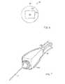
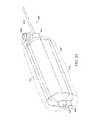
- FIG. 7shows a perspective view of a miniature needle endoscope in accordance with the invention.
- Fiber and electrical cablesare connected to the proximal end of handle 16 or needle 12 for insertion into a patient is attached at a distal end of handle 16 .
- a preferred embodiment of the inventioncan be considered as three subassemblies.
- a first subassembly shown in FIG. 9is the outer handle housing 120 having a distal rod connector 122 .
- a second subassemblyis the inner handle 140 shown in FIG. 12 .
- Inner handle 140includes proximally located fiber and electrical connectors 142 and 144 that are attached to an inner cage assembly 146 .
- the fiber connector 142connects light from an external source to an illumination annulus 154 which couples light to an illumination channel 308 in needle 240 as shown in FIG. 19 .
- Light collected through needle 240is coupled to lenses 150 and 152 onto an imaging sensor such as CCD 148 .
- FIGS. 9 and 12 - 14illustrate a disposable third assembly having a rod and needle with a distal lens assembly 162 that is attached to a sterile sleeve assembly 160 .
- the sleeve assembly 160includes a sleeve 164 that extends over the handle or base unit 202 .
- the distal end of sleeve 164is secured between plastic frames 166 , 170 which can form a mounting hub 218 .
- Frame 166has a hole 168 that connects to rod and lens assembly 162 .
- Frame 170connects to rod connector or interface connector 122 .
- FIG. 8illustrates an endoscope, identified generally as 130 .
- the endoscope 130can have an optical system 123 and a handle 124 .
- the optical system 123can include a tube 103 having a distal end 112 , a proximal end 111 and distal optics 117 and can have an outer diameter between 0.6 and 2.0 mm with a preferred outer diameter of about 1.6 mm.
- the optical system 123can be disposable.
- the handle portion 124can include proximal optics 105 , an image polarizer 106 , an image sensor 107 and a beam splitter 104 .
- the proximal optics 105can include an achromatic lens.
- the beam splitter 104can be coated with a dielectric coating.
- the beam splitter coatingcan be designed to provide maximum reflection of “s polarized” illumination flux and maximum transmission of “p polarized” image light.
- the curvature of the distal optics 117can be chosen to minimize retro-reflections of illumination flux appearing in the image.
- the endoscope 130can have a duplex configuration wherein the duplex configuration integrates illumination optics and uses the beam splitter 104 to direct illumination energy along the same optical path used for image light transfer.
- Duplexrefers to the optical components and optical path used by illumination flux and image light.
- an object plane 101can be located from 2 to 20 mm in front of a distal tip 126 of the endoscope 130 .
- the distal optics 117form a demagnified virtual image 114 , located just outside the distal tip 126 .
- a narrow beam of image light from the virtual image 114can pass through the tube 103 , through a dielectric coated beam splitter 104 , toward proximal optics 105 , and eventually to an image sensor 107 , where a real image is formed.
- Image polarizer 106can be a linear polarizer that is “crossed” with an illumination polarizer 108 to block retro-reflected illumination flux originating from surfaces of the distal optics.
- the tube 103can be a stainless steel extrusion having a rough inner surface which can be coated with a light absorbing coating, such as spray paint.
- a light absorbing coatingsuch as spray paint.
- Krylon #1602a dull black paint can be used.
- the tube 103can have an inner diameter of 1.5 mm with the light absorbing inner wall to reduce or eliminate veiling or scattered light at the image sensor 107 .
- the tube 103can be filled with air or some other inert gas, or can be evacuated.
- the image channel or image relay 103functions to minimize or absorb unwanted light and hard to image light to prevent veiling glare.
- the image relay 103provides high resolution of the optical image, 114 at the plane of the imaging device, removes intermediate image planes and reduces the tolerances needed for optical alignment and optical fabrication.
- the image relay 103has an inner tunnel wall that can absorb light diverging from the optics 117 .
- the rough wall surfacecan disperse up to about 95% or more of unwanted light.
- the image relay 103can have a length to diameter (L to D) ratio of between 40:1 and 60:1.
- the length of the tunnelcan be approximately 60 mm.
- the length of the image relay 103affects proper illumination of an imaging device, helps control depth of field of view, increases F number for adequate depth of field of view.
- the image relay 103can also be disposable.
- the optical element or distal optics 117 on the tube 103can be a polymer lens or an epoxy lens.
- the distal opticscan have a diameter of 1.5 mm.
- the distal optics 117can be a single distal lens to reduce retro-reflections.
- the distal optics 117can be formed from an epoxy using an injection method. In this method a mandrel can first be placed within the tube 103 from the distal end 112 to the proximal end 111 . Epoxy can then be ejected from the needle within 1 mm of the distal end 112 of the tube 103 . The epoxy can then be exposed to ultraviolet (UV) light to cure the epoxy.
- UVultraviolet
- the distal optics 117can be formed as a concave/negative lens because of the capillary action caused by the air tube 103 after ejection of the epoxy from the needle.
- the distal 117 and proximal 105 opticscan allow control of the size of an image.
- the area surrounding the proximal end 111 of the tubecan be carefully sculpted and blackened to reduce retro-reflected energy at the image sensor 107 originating from the illumination flux overfill of the air tube 103 .
- the proximal optics 105are “looking at” this overfill area and the image polarizer 106 can transmit scattered, unpolarized light to the image sensor 107 .
- the endoscope 130can be linked via'beamsplitter 104 to an illumination system 116 .
- the illumination system 116can include an illumination source 110 such as a COTS lens end Halogen Lamp having a 0.25 inch diameter from Gilway Technical Lamp.
- the COTS “Lens End” lampcan have high flux output from a small filament.
- the illumination source 110can provide high color temperature visible light for object plane 101 illumination.
- Source optics 109can concentrate illumination flux at the proximal end 111 of the tube 103 and provide a low divergence beam to maximize transmission of illumination flux through the tube 103 .
- a beam splitter 104can redirect illumination flux along an image light axis 115 .
- Illumination polarizer 108is a linear polarizer oriented to provide “s polarization” at the beam splitter to maximize reflection of illumination flux from dielectric coated beam splitter 104 , along axis 115 .
- a light absorbing mechanism or beam dump 113can remove unused portion of illumination flux from the system to reduce veiling background light that can find its way onto the image sensor.
- Illumination opticsmust be carefully designed to maximize illumination at object plane.
- the illumination opticscreate a small spot of light at proximal end of air tube and a collimated beam for maximum transmission through air tube.
- Illumination and image polarizersmust provide high polarization purity with minimum absorption.
- dichroic sheet polarizerscan be inexpensive, but lossy.
- Calcite polarizerscan be more efficient, but expensive and more difficult to accommodate in a simple optical design.
- Unused illumination flux transmitted by the beam splittermust be completely removed from the system because the proximal optics are “looking at” the dump area 113 .
- the image polarizerwill transmit scattered, unpolarized light to the image sensor.
- the endoscope 130can be inserted into a body using a cannula.
- a cannulacan first be inserted into a site within a body.
- the optical system 123 of the endoscope 130can then be inserted within the cannula which can have an outer diameter of 1.6 mm.
- the optical system 123can pass through the cannula and into the body to provide the user with an image of the site.
- the systemcan be used with a disposable sleeve or sheath to aid in maintaining a sterile environment and reduce the sterilization requirements prior to reuse.
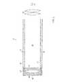
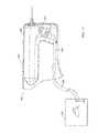
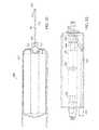
- FIGS. 9 and 10illustrate a miniature endoscope, given generally as 200 , in both a side and a perspective view respectively.
- the endoscope 200can include a base unit 202 and a sheath assembly 160 .
- the base unitcan include a cable 224 which can provide power to an internal light source within the base unit 202 .
- the sheath assemblycan include a sterile barrier 164 and a probe or rod and lens assembly 162 .
- the rod and lens assembly 162can be formed of a rod or waveguide 204 and a object lenses 206 .
- the waveguidecan be a hollow channel.
- the probecan have an annular illumination channel around the waveguide.
- the probecan have a length between 2 cm and 10 cm.
- the sterile barrier 164 and the rod and lens assembly 162can be attached to a mounting hub 218 or second locking element which secures to a first locking element of the base unit 202 of the endoscope 200 .
- the hub 218can include an interface connection 122 or first locking element that allows the sheath assembly 160 to attach to the base unit 202 .
- the interface connection 122can be a securing mechanism such as a locking mechanism.
- the sterile barrier 164can attach to the mounting hub 218 by bonding. The bonding can include cementing between the sterile barrier 164 and the hub 218 , for example.
- the mounting hub 218can include a locking mechanism 216 such as a luer lock for example.
- the locking mechanism 216can allow connection between the miniature endoscope 200 and a needle such as a 14 gage cannula, for example (manufactured by Popper).
- the rod and lens assembly 162can include a rod tip 226 illustrated in FIG. 11 .
- the rod tip 226can have object lenses 206 . These object lenses can include a first object lens 208 and a second object lens 210 .
- the rod 204 of the rod and lens assembly 162can be covered by a tube 214 or light absorbing boundary. The tube can be a dark coating in order to reduce or eliminate veiling or scattered light within the rod 204 .
- the sterile barrier 164 of the sheath assembly 160can cover the entire base unit 202 . This covering provides a sterility of the base unit 202 during a surgical procedure.
- the miniature endoscope 200can be inserted into a cannula or needle 240 as illustrated in FIGS. 12-16 .
- the needle 240has a blunt end.
- the needlecan be a 14 gauge needle.
- a sheath assembly 160can first be placed on a base unit 202 .
- the rod and lens assembly 162 of the sheath assembly 160can lock into the interface connection 122 of the base unit 202 .
- a needle or cannula 240having a stylet 320 , such as seen in FIG. 20 , slidably mounted within the cannula, can be inserted into a surgical site.
- the stylet 320can cut into the tissue of a surgical site and thereby allow the needle 240 to be inserted into the surgical site.
- the stylet 320can then be removed from the cannula 240 .
- the stylet or obturator 320fills the center portion of the cannula during insertion into a surgical site.
- the use of the styletprevents coring of tissue, whereby a cylindrical portion of tissue enters the needle or cannula 240 and can clog the needle cavity. By having a stylet within the needle 240 , no such tissue can enter the cannula 240 and can clog the needle cavity.
- the usercan flush the surgical site with saline.
- the rod and lens assembly 162 of the miniature endoscope 200can be introduced into the needle 240 .
- the rod portion 204can be inserted within the needle 240 so that a user can obtain a view of the surgical site.
- the needlecan include a locking mechanism on its proximal end, such as a luer lock for example.
- the luer lockcan attach to the locking mechanism 216 of the mounting hub 218 thereby providing a secure attachment between the endoscope 200 and the needle 240 .
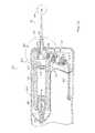
- FIGS. 12 , 13 and 14illustrate a cross sectional view of the miniature endoscope 200 .
- the endoscope 200can include a lighting system or light source 236 and an imaging system 238 .
- the lighting system 236can include a lamp 242 , a polarizer 244 and a lens expander 246 .
- the lamp 242can be mounted within the base unit 202 by a light source housing 270 and can be a high output light source.
- the polarizer 244can polarize light from the light source and direct light towards the expander 246 .
- the lens expander 246can direct light towards a prism 264 .
- the imaging system 238 of the endoscope 200can include a first image path lens 150 , a second image path lens 152 and a sheet polarizer 252 .
- the imaging systemcan be mounted within a housing 140 .
- the sheet polarizer 252can help to eliminate back reflections from the rod and lens assembly 162 .
- the polarizer 252can have a polarization purity of 10 ⁇ 3 .
- FIG. 13illustrates a light transfer and imaging system 262 of the endoscope 200 of FIG. 12 .
- the light transfer and imaging system 262can include a beamsplitter 264 which can be mounted within a housing 266 in the endoscope 200 .
- the beamsplitter 264can be a prism for example.
- the beamsplitter 266can direct light from the lens expander 246 into the rod 204 of the rod and lens assembly 162 . This light can be directed at an object to be imaged.
- the beamsplitter 264can also receive image light through the rod or channel 204 of an object being imaged and transfer that light to the polarizer 252 of the imaging system 238 .
- the beamsplitter 264can be mounted within the endoscope 200 at a Brewster's angle with such a mounting.
- the beamsplitter 264 in this examplecan form a 33.5° angle with respect to the long axis 272 of the rod.
- the beamsplitter 264can also form a 33.5° angle with respect to the central axis of the imaging system 238 .
- FIG. 12also illustrates an image sensor 148 mounted within the base unit 202 of the endoscope 200 .
- the image sensor 148can be mounted within an image sensor housing 258 within the endoscope 200 .
- the image sensor 148can be attached to an electrical cable connector 254 whereby the cable connector 254 can attach to a cable 230 to provide image signal data from an object being imaged to an external unit.
- the external unitcan be a television screen, for example.
- the image sensor 148can be a charge coupled device (CCD).
- the CCDcan be a 1 ⁇ 8 inch CCD. By using a 1 ⁇ 8 inch CCD, the user can quadruple the amount of light he receives from an image.
- the focal length of the endoscope 200can be between 25 and 30 mm. Preferably the focal length is 27 mm.
- FIG. 14illustrates the rod tip 260 of the miniature endoscope 200 whereby the rod tip 260 includes the first object lens 208 , the second object lens 210 and a dark coating or tube 214 around a rod 204 .
- the rod tip 260is mounted within a needle or cannula 240 .
- Such insertion of the rod tip 260 within the cannula 240can be done after the cannula 240 is inserted into a surgical site of interest.
- the cannula 240can lock on to the base unit 202 by means of a locking mechanism.
- FIGS. 15 and 16illustrate an alternate to the imaging system 238 illustrated in FIGS. 12 , 13 and 14 .
- the imaging system 238can include a first image path lens 150 , a second image path lens 152 and a polarizer 280 .
- the cross polarizer 280can be made from cal cite and can eliminate back reflections created by the rod and lens assembly 162 .
- the polarization purity of the cross polarizercan be between 10 ⁇ 5 and 10 ⁇ 6 .
- the cross polarizer 280can increase light throughout by 15% to 20%.
- the polarizer 280can include a first prism 282 and a second prism 284 .
- the polarizer 280can be attached to the housing 140 of the endoscope 200 by a polarizer housing 286 .
- FIG. 16illustrates the light transfer and imaging system 262 of FIG. 15 .
- Light directed from the lens expander 246can be sent through the beamsplitter 264 and into the rod 204 to an object being imaged.
- Light from the object being imagedcan be transferred back through the rod 204 and through the prism 264 into the beamsplitter 280 .
- the beamsplittercan transfer the image light to the polarizer 280 which can eliminate back reflections created by the object lenses 206 .
- FIG. 17illustrates a miniature endoscope 200 where the light source of the endoscope 200 is an external light source 290 .
- the external light sourcecan include a lamp 292 and light source optics 294 .
- the lamp 292can be a xenon lamp which can be 300 watts, for example.
- the optics 294 and lamp 292 of the external light source 290can be coupled to the miniature endoscope 200 by a silica cable 296 .
- the endoscope 200can include a reducer 298 mounted within the base unit 202 .
- the reducer 298can reduce the cross sectional area of the source by a factor of 2-5 times. Preferably the reducer reduces by a factor of 3.5.
- the reducer 298can reduce the aperture size of source for efficient coupling into the probe waveguide.
- the use of a reducer 298 within the endoscope 200can simplify the optics within the lighting system 236 .
- FIG. 18shows a configuration of the endoscope 200 wherein the lighting system 236 is mounted within the base unit 202 parallel to the imaging system 238 .
- the lighting system 236can include a mirror 302 .
- the mirror 302can be a fold mirror for example.
- the mirror 302can be mounted within the endoscope 200 such that light from a light source 242 which travels through a polarizer 244 and an expander 246 can reflect from the mirror to travel to the prism 264 .
- FIG. 19illustrates the cross section of a needle 240 wherein the needle acts a reducer to provide light to an object being imaged.
- the needle 240can include an aperture 304 .
- the aperturecan be surrounded by a first cladding layer 306 , an illumination channel 308 and a second cladding layer 310 .
- the first cladding layercan have a first cladding layer thickness 312 .
- the illumination channel 308can include a channel thickness 314 which can be 10 microns.
- the second cladding layer 310can include a second cladding thickness 316 whereby the thickness can be 3 microns.
- FIG. 20illustrates a cannula 240 having a stylet.
- a stylet or obturatorPrior to inserting a needle 240 into a surgical site, a stylet or obturator can be inserted within the needle 240 .
- the styletcan include a cutting surface 322 and a cleaning edge 324 .
- tissuecan accumulate in an area between the stylet 320 and the needle 240 .
- the stylet 320can include a cleaning edge 324 whereby the cleaning edge is formed of a less stiff material than is the cutting edge 322 .
- the weaker edge or the cleaning edge 324will bend about the needle thereby cleaning or wiping away any tissue debris from the needle area. Such a cleaning function allows proper insertion of the microendoscope within the cannula and proper viewing of a surgical site.
- FIG. 21shows a miniature endoscope 400 in side perspective view.
- the endoscope 400includes a base unit 402 and a sheath assembly 404 .
- the base unit 402includes an electrical connection 406 for the imaging device, such as a CCD and a fiber optic light source connection 408 .
- the sheath assembly 404includes a sterile barrier 410 and a rod and lens assembly 412 .
- the sterile barrier 410 and the rod and lens assembly 412are attached to a mounting hub 414 , which is secured to the base unit 402 of the endoscope 400 .
- the mounting hub 414is a light sheath hub with luer lockside port.
- the hub 414can include an interface connection 416 that allows the sheath assembly 404 to attach to the base unit 402 .
- the interface connection 416can be a securing mechanism such as a locking mechanism.
- the sterile barrier 410as seen in FIG. 22 , is attached to the mounting hub 414 by bonding.
- the bondingcan include cementing between the sterile barrier 410 and the hub 414 , for example.
- the mounting hub 414can include a locking mechanism 418 such as a luer lock or fitting for example.
- the locking mechanism 418can allow connection between the miniature endoscope 400 and a needle such as a 14 gage cannula, for example (manufactured by Popper).
- FIG. 22a sectional view of the endoscope 400 is shown.
- the sheath assembly 404 with the rod and lens assembly 412 and sterile barrier 410is shown.
- the sterile barrier 410 and the rod and lens assembly 412are attached to the mounting hub 414 .
- the mounting hub 414has a fiber optic window 420 which transmits light from a light source to a light sheath in an obturator.
- the window 420can be a lens.
- the rod and lens assembly 412has a darkened outer tube 422 and a pair of object lenses 424 .
- the distal end of the rod and lens assembly 412will be discussed in further detail with reference to FIG. 27B .
- the base unit 402 of the endoscope 400has a main scope body 428 with the CCD camera 430 , a set of lenses 432 , and a fiber optic tip mount 434 and fiber optic bundle 436 which define an opening 438 through which an optical image passes from the rod and lens assembly 412 towards the CCD camera 430 .
- the opening 438can be covered by a window or a lens.
- underlying the main scope by 428is a fiber optic 442 which extends from the fiber optic light source connection 408 to fiber optic bundle 436 .
- FIG. 24shows the rear portion of the base unit 402 of the endoscope 400 .
- the electrical connection 406is seen and in addition the fiber optic light source connection 408 is shown.
- the base unit 402has a plurality of fiber optic fibers 444 forming an annulus 445 surrounding the opening 438 as seen in FIG. 25B .
- the fiber optic bundle 436is formed of these fiber optic fibers 444 in one embodiment. Alternately, the fiber optic bundle 436 has a single fiber optic fiber.
- the annulus 445can be a continuous circular pattern. Alternately, the annulus is formed of two semicircular portions 457 .
- a slot 459can separate the semicircular portions 457 . The slot 459 can allow mechanical attachment of the light sheath 422 , shown in FIG. 27B to the hub 446 .
- FIG. 26a side sectional view of the endoscope 400 is shown.
- the main scope body 428as indicated above, has the CCD camera 430 which is connected through the electrical connection 406 to a monitor, such as illustrated in FIG. 1 .
- the CCD camera 430captures the image projected through the set of lenses 432 that is projected from the high index glass rod of the sheath assembly 404 . While the sheath assembly is solid, the image that is projected through the lens 432 in the main scope body is through the opening 438 .
- the fiber optics 442directs the light from the fiber optic light source connection 408 to the fibre optic bundle 436 .
- the fiber optic bundle 436can be formed of a plurality of fiber optics or from a single fiber optic.
- the fiber optic bundle 436projects its light through the lens 432 into the light sheath 448 .
- the lens 432can be a window, in an alternate embodiment.
- the connector between the bundle 436 and the lens 432is shown in FIG. 29A .
- the disposable optic tube hub connector 446 with lens 432can attach to an obturator or needle having a flushing port 450 , as shown in FIG. 26 .
- the flushing port 450can include a cap 452 .
- the flushing port 450allows a user the ability to flush a needle, after insertion into a surgical site, either when the rod and lens assembly 412 is located within the needle or has been removed from the needle.
- a fluid sourcesuch as a syringe filled with saline, for example, can be attached to the port 450 .
- the endoscopecan block fluid from flowing from a proximal end of the needle, thereby concentrating flow through a distal end located within a surgical site.
- the cap 452can be used to cover the proximal end of the needle to direct the flow of the fluid to the distal end of the needle. Such flushing can allow clear viewing of a surgical site.
- the distal end of the sheath assembly 404has the light sheath 448 and encircles the disposable optic dark tube 422 containing the object lenses 424 .
- Lightcan be transferred from the fiber optic bundle 436 through the light sheath and to an object being imaged.
- FIG. 28is a sectional view taken along the line 28 - 28 of FIG. 26 .
- the figureshows a sectional view of the main scope body 428 cut through and looking up from the optical opening 438 .
- the CCD 430 with connection 406is shown.
- the lens 432 through which the image projectare shown.
- the fiber optic bundle 436through which light is passed from the fiber optic 442 , as shown in FIG. 26 , encircles a portion of the optical opening 438 and directs light through the lens 432 in the disposable optics dark tube hub connector 446 into the light sheath surrounding the rod and lens assembly 412 .
- FIG. 29Ais an enlarged sectional view of the interface of the fiber optic bundle 436 , the disposable optics dark tube hub connector 446 and the mounting hub 414 .
Landscapes
- Health & Medical Sciences (AREA)
- Life Sciences & Earth Sciences (AREA)
- Surgery (AREA)
- Nuclear Medicine, Radiotherapy & Molecular Imaging (AREA)
- Biomedical Technology (AREA)
- Optics & Photonics (AREA)
- Pathology (AREA)
- Radiology & Medical Imaging (AREA)
- Biophysics (AREA)
- Engineering & Computer Science (AREA)
- Physics & Mathematics (AREA)
- Heart & Thoracic Surgery (AREA)
- Medical Informatics (AREA)
- Molecular Biology (AREA)
- Animal Behavior & Ethology (AREA)
- General Health & Medical Sciences (AREA)
- Public Health (AREA)
- Veterinary Medicine (AREA)
- Endoscopes (AREA)
Abstract
Description
Claims (42)
Priority Applications (3)
| Application Number | Priority Date | Filing Date | Title |
|---|---|---|---|
| US09/660,840US8317689B1 (en) | 1999-09-13 | 2000-09-13 | Miniature endoscope system |
| US09/813,939US20020087047A1 (en) | 1999-09-13 | 2001-03-21 | Miniature endoscope system |
| US13/658,458US20130046142A1 (en) | 1999-09-13 | 2012-10-23 | Miniature endoscope system |
Applications Claiming Priority (6)
| Application Number | Priority Date | Filing Date | Title |
|---|---|---|---|
| US15356899P | 1999-09-13 | 1999-09-13 | |
| US15647899P | 1999-09-28 | 1999-09-28 | |
| US18730500P | 2000-03-06 | 2000-03-06 | |
| US51895400A | 2000-03-06 | 2000-03-06 | |
| US21293500P | 2000-06-20 | 2000-06-20 | |
| US09/660,840US8317689B1 (en) | 1999-09-13 | 2000-09-13 | Miniature endoscope system |
Related Parent Applications (1)
| Application Number | Title | Priority Date | Filing Date |
|---|---|---|---|
| US51895400AContinuation-In-Part | 1999-09-13 | 2000-03-06 |
Related Child Applications (2)
| Application Number | Title | Priority Date | Filing Date |
|---|---|---|---|
| US09/813,939Continuation-In-PartUS20020087047A1 (en) | 1999-09-13 | 2001-03-21 | Miniature endoscope system |
| US13/658,458DivisionUS20130046142A1 (en) | 1999-09-13 | 2012-10-23 | Miniature endoscope system |
Publications (1)
| Publication Number | Publication Date |
|---|---|
| US8317689B1true US8317689B1 (en) | 2012-11-27 |
Family
ID=47190818
Family Applications (2)
| Application Number | Title | Priority Date | Filing Date |
|---|---|---|---|
| US09/660,840Expired - Fee RelatedUS8317689B1 (en) | 1999-09-13 | 2000-09-13 | Miniature endoscope system |
| US13/658,458AbandonedUS20130046142A1 (en) | 1999-09-13 | 2012-10-23 | Miniature endoscope system |
Family Applications After (1)
| Application Number | Title | Priority Date | Filing Date |
|---|---|---|---|
| US13/658,458AbandonedUS20130046142A1 (en) | 1999-09-13 | 2012-10-23 | Miniature endoscope system |
Country Status (1)
| Country | Link |
|---|---|
| US (2) | US8317689B1 (en) |
Cited By (40)
| Publication number | Priority date | Publication date | Assignee | Title |
|---|---|---|---|---|
| US20080064925A1 (en)* | 2001-10-19 | 2008-03-13 | Gill Thomas J | Portable imaging system employing a miniature endoscope |
| US20100284580A1 (en)* | 2009-05-07 | 2010-11-11 | Ouyang Xiaolong | Tissue visualization systems and methods for using the same |
| US20110112359A1 (en)* | 2009-11-06 | 2011-05-12 | Mark Joseph L | Surgical adapter assembly for use with endoscope |
| US20140221740A1 (en)* | 2013-02-05 | 2014-08-07 | Paul John Kawula | Wireless endoscopic surgical device |
| WO2014126757A3 (en)* | 2013-02-15 | 2014-10-16 | Nico Corporation | Surgical interface for use with endoscope |
| USD716841S1 (en) | 2012-09-07 | 2014-11-04 | Covidien Lp | Display screen with annotate file icon |
| USD717340S1 (en) | 2012-09-07 | 2014-11-11 | Covidien Lp | Display screen with enteral feeding icon |
| US20150011825A1 (en)* | 2012-02-24 | 2015-01-08 | L'HELGOUAL'CH, Guy | Endoscopic device intended, in particular, for a medical usage |
| USD735343S1 (en) | 2012-09-07 | 2015-07-28 | Covidien Lp | Console |
| US9198835B2 (en) | 2012-09-07 | 2015-12-01 | Covidien Lp | Catheter with imaging assembly with placement aid and related methods therefor |
| US9343489B2 (en) | 2011-05-12 | 2016-05-17 | DePuy Synthes Products, Inc. | Image sensor for endoscopic use |
| US9370295B2 (en) | 2014-01-13 | 2016-06-21 | Trice Medical, Inc. | Fully integrated, disposable tissue visualization device |
| US20160231555A1 (en)* | 2015-02-09 | 2016-08-11 | Visicon Technologies, Inc. | Borescope Inspection System |
| US9433339B2 (en) | 2010-09-08 | 2016-09-06 | Covidien Lp | Catheter with imaging assembly and console with reference library and related methods therefor |
| US20160278615A1 (en)* | 2013-02-05 | 2016-09-29 | Scopernicus, LLC | Wireless endoscopic surgical device |
| US9462234B2 (en) | 2012-07-26 | 2016-10-04 | DePuy Synthes Products, Inc. | Camera system with minimal area monolithic CMOS image sensor |
| US9468367B2 (en) | 2012-05-14 | 2016-10-18 | Endosee Corporation | Method and apparatus for hysteroscopy and combined hysteroscopy and endometrial biopsy |
| US20160324409A1 (en)* | 2014-01-23 | 2016-11-10 | Olympus Corporation | Endoscope light source system |
| US9517184B2 (en) | 2012-09-07 | 2016-12-13 | Covidien Lp | Feeding tube with insufflation device and related methods therefor |
| US9622646B2 (en) | 2012-06-25 | 2017-04-18 | Coopersurgical, Inc. | Low-cost instrument for endoscopically guided operative procedures |
| US20180055596A1 (en)* | 2016-08-25 | 2018-03-01 | Novartis Ag | Planar illuminator for ophthalmic surgery |
| US10045686B2 (en) | 2008-11-12 | 2018-08-14 | Trice Medical, Inc. | Tissue visualization and modification device |
| US20180279855A1 (en)* | 2015-03-30 | 2018-10-04 | Acclarent, Inc. | Guide catheter with image capture and light emission features |
| US10342579B2 (en) | 2014-01-13 | 2019-07-09 | Trice Medical, Inc. | Fully integrated, disposable tissue visualization device |
| US10405886B2 (en) | 2015-08-11 | 2019-09-10 | Trice Medical, Inc. | Fully integrated, disposable tissue visualization device |
| US10429627B2 (en) | 2014-11-24 | 2019-10-01 | University Of Utah Research Foundation | Computational microscopy through a cannula |
| US10441134B2 (en) | 2011-05-03 | 2019-10-15 | Coopersurgical, Inc. | Method and apparatus for hysteroscopy and endometrial biopsy |
| US10517469B2 (en) | 2013-03-15 | 2019-12-31 | DePuy Synthes Products, Inc. | Image sensor synchronization without input clock and data transmission clock |
| US10702305B2 (en) | 2016-03-23 | 2020-07-07 | Coopersurgical, Inc. | Operative cannulas and related methods |
| US10750933B2 (en) | 2013-03-15 | 2020-08-25 | DePuy Synthes Products, Inc. | Minimize image sensor I/O and conductor counts in endoscope applications |
| US10996456B2 (en) | 2016-04-25 | 2021-05-04 | Panasonic I-Pro Sensing Solutions Co., Ltd. | Endoscope and camera module |
| US11096557B2 (en) | 2016-03-14 | 2021-08-24 | Eyelum Ltd. | Endoscopy system having a miniature closed head |
| US11382492B2 (en) | 2013-02-05 | 2022-07-12 | Scopernicus, LLC | Wireless endoscopic surgical device |
| US11484189B2 (en) | 2001-10-19 | 2022-11-01 | Visionscope Technologies Llc | Portable imaging system employing a miniature endoscope |
| US11547446B2 (en) | 2014-01-13 | 2023-01-10 | Trice Medical, Inc. | Fully integrated, disposable tissue visualization device |
| US11547282B2 (en)* | 2016-05-25 | 2023-01-10 | avateramedical GmBH | Arrangement for the sterile handling of non-sterile units in a sterile environment |
| US11622753B2 (en) | 2018-03-29 | 2023-04-11 | Trice Medical, Inc. | Fully integrated endoscope with biopsy capabilities and methods of use |
| WO2023215578A1 (en) | 2022-05-05 | 2023-11-09 | Intravu Inc. | Miniature angle-view endoscope with image orientation correction |
| US11849917B2 (en) | 2017-09-11 | 2023-12-26 | Eyelum Ltd. | Disposable miniature endoscopy system |
| US12035889B2 (en) | 2008-07-22 | 2024-07-16 | Trice Medical, Inc. | Tissue modification devices and methods of using the same |
Families Citing this family (10)
| Publication number | Priority date | Publication date | Assignee | Title |
|---|---|---|---|---|
| US20100286477A1 (en)* | 2009-05-08 | 2010-11-11 | Ouyang Xiaolong | Internal tissue visualization system comprising a rf-shielded visualization sensor module |
| US20110009694A1 (en)* | 2009-07-10 | 2011-01-13 | Schultz Eric E | Hand-held minimally dimensioned diagnostic device having integrated distal end visualization |
| US10869592B2 (en) | 2015-02-23 | 2020-12-22 | Uroviu Corp. | Handheld surgical endoscope |
| US11684248B2 (en) | 2017-09-25 | 2023-06-27 | Micronvision Corp. | Endoscopy/stereo colposcopy medical instrument |
| US11832797B2 (en) | 2016-09-25 | 2023-12-05 | Micronvision Corp. | Endoscopic fluorescence imaging |
| US11771304B1 (en) | 2020-11-12 | 2023-10-03 | Micronvision Corp. | Minimally invasive endoscope |
| US11980342B2 (en)* | 2020-11-12 | 2024-05-14 | Micronvision Corp. | Minimally invasive endoscope |
| US12268358B2 (en) | 2019-12-05 | 2025-04-08 | Uroviu Corp. | Portable endoscope with side-mountable disposable portion |
| EP4003138A4 (en) | 2019-07-25 | 2023-08-30 | Uroviu Corp. | DISPOSABLE ENDOSCOPY NEEDLE WITH INTEGRATED GRIPPER |
| CN111552026A (en)* | 2020-04-10 | 2020-08-18 | 桂林电子科技大学 | Optical fiber and system for human body intervention visual photodynamic therapy |
Citations (128)
| Publication number | Priority date | Publication date | Assignee | Title |
|---|---|---|---|---|
| US1692554A (en)* | 1923-02-01 | 1928-11-20 | Josef Leiter Fabrik Chirurgisc | Device for illuminating all kinds of hollow members |
| US3261349A (en) | 1963-08-29 | 1966-07-19 | American Cystoscope Makers Inc | Endoscope |
| US3724922A (en)* | 1970-12-17 | 1973-04-03 | I Jones | Scope for viewing the internal surface of a bore of similar cavity |
| US3784386A (en)* | 1971-02-16 | 1974-01-08 | Corning Glass Works | Cladding glasses for photochromic optical fibers |
| US3902880A (en)* | 1974-01-16 | 1975-09-02 | American Optical Corp | Method of making a fiber optic illuminating halo |
| US3941121A (en)* | 1974-12-20 | 1976-03-02 | The University Of Cincinnati | Focusing fiber-optic needle endoscope |
| US4254762A (en)* | 1979-10-23 | 1981-03-10 | Inbae Yoon | Safety endoscope system |
| EP0072205A1 (en) | 1981-08-05 | 1983-02-16 | Olympus Optical Co., Ltd. | Endoscope cover glass fitting |
| US4569334A (en)* | 1981-05-22 | 1986-02-11 | Fuji Photo Optical Co., Ltd. | Apparatus for restoring the light transmittance of an image-transmitting optical fiber bundle used in a fiber optic endoscope |
| US4593973A (en)* | 1982-06-26 | 1986-06-10 | Sumitomo Electric Industries, Ltd. | Composite optical fiber and imaging catheter and method for producing the same |
| US4607622A (en) | 1985-04-11 | 1986-08-26 | Charles D. Fritch | Fiber optic ocular endoscope |
| US4610242A (en)* | 1984-04-18 | 1986-09-09 | Codman & Shurtleff, Inc. | Endoscope insertion cannula assembly |
| US4641912A (en)* | 1984-12-07 | 1987-02-10 | Tsvi Goldenberg | Excimer laser delivery system, angioscope and angioplasty system incorporating the delivery system and angioscope |
| US4755029A (en) | 1986-05-22 | 1988-07-05 | Olympus Optical Co., Ltd. | Objective for an endoscope |
| US4790295A (en)* | 1986-12-16 | 1988-12-13 | Olympus Optical Co., Ltd. | Endoscope having transparent resin sealing layer |
| US4802461A (en) | 1987-08-26 | 1989-02-07 | Candela Laser Corporation | Rigid endoscope with flexible tip |
| US4807597A (en)* | 1985-01-14 | 1989-02-28 | Sumitomo Electric Industries, Ltd. | Fiberscope |
| EP0316244A1 (en) | 1987-11-12 | 1989-05-17 | Welch Allyn, Inc. | Video equipped endoscope with needle probe |
| US4878485A (en) | 1989-02-03 | 1989-11-07 | Adair Edwin Lloyd | Rigid video endoscope with heat sterilizable sheath |
| DE8814573U1 (en) | 1988-11-18 | 1990-01-11 | BIOMET Deutschland GmbH, 14167 Berlin | endoscope |
| US4904246A (en) | 1988-07-19 | 1990-02-27 | Snyder Laboratories, Inc. | Cannula assembly |
| US4921326A (en) | 1989-03-23 | 1990-05-01 | Victor F. Wild | Fiber optic probe |
| US4947245A (en) | 1988-05-23 | 1990-08-07 | Sumitomo Electric Industries, Ltd. | Image picking-up and processing apparatus |
| US4963960A (en)* | 1988-06-01 | 1990-10-16 | Kabushiki Kaisha Toshiba | Electronic endoscope apparatus employing automatic light source control |
| US4972827A (en)* | 1989-02-06 | 1990-11-27 | Fuji Photo Optical Co., Ltd. | Guide device for percutaneous insertion of endoscope |
| US4979498A (en) | 1989-10-30 | 1990-12-25 | Machida Incorporated | Video cervicoscope system |
| EP0461669A1 (en)* | 1990-06-15 | 1991-12-18 | Nihon Kohden Corporation | Structure of rod lens for endoscopes |
| US5074642A (en) | 1989-11-14 | 1991-12-24 | Hicks John W | Multifiber endoscope with fibers having different indices of refraction |
| US5121740A (en) | 1991-05-06 | 1992-06-16 | Martin Uram | Laser video endoscope |
| US5159919A (en) | 1990-02-01 | 1992-11-03 | Machida Endoscope Co., Ltd. | Endoscope cover |
| US5168863A (en)* | 1990-08-27 | 1992-12-08 | Medical Concepts, Inc. | Sterile endoscopic system |
| US5172685A (en) | 1988-05-27 | 1992-12-22 | The University Of Connecticut | Endoscope and video laser camera system therefor |
| US5183031A (en)* | 1991-05-13 | 1993-02-02 | Rossoff Leonard J | Fiberoptic intubating laryngoscope |
| US5184602A (en)* | 1988-11-18 | 1993-02-09 | Effner Biomet Gmbh | Endoscope, in particular an arthroscope |
| EP0549097A1 (en) | 1991-12-24 | 1993-06-30 | Citation Medical Corporation | Portable arthroscope with periscope optics |
| US5237984A (en) | 1991-06-24 | 1993-08-24 | Xomed-Treace Inc. | Sheath for endoscope |
| US5274500A (en) | 1992-07-23 | 1993-12-28 | Kansas City Medical, Inc. | Video camera drape with lens |
| US5290279A (en) | 1991-12-19 | 1994-03-01 | Meditron Devices, Inc. | Arthroscopic tool combining five functions in one |
| EP0586162A1 (en) | 1992-08-24 | 1994-03-09 | Ethicon Inc. | Glare elimination device |
| US5319731A (en)* | 1992-10-02 | 1994-06-07 | Eastman Kodak Company | Fiber-optic array of limited acceptance angle |
| US5323766A (en) | 1991-05-06 | 1994-06-28 | Endo Optiks Corporation | Illuminating endo-photocoagulation probe |
| US5323767A (en)* | 1991-02-04 | 1994-06-28 | Citation Medical Corporation | Portable arthroscope with periscope optics |
| US5329936A (en)* | 1991-02-04 | 1994-07-19 | Citation Medical Corporation | Portable arthroscope with periscope optics |
| US5337734A (en) | 1992-10-29 | 1994-08-16 | Advanced Polymers, Incorporated | Disposable sheath with optically transparent window formed continuously integral therewith |
| US5341240A (en) | 1992-02-06 | 1994-08-23 | Linvatec Corporation | Disposable endoscope |
| US5347990A (en) | 1992-10-08 | 1994-09-20 | Wendell V. Ebling | Endoscope with sterile sleeve |
| US5369525A (en) | 1992-12-02 | 1994-11-29 | United States Surgical Corporation | Ring lens assembly for an optical viewing device |
| US5402768A (en) | 1992-09-01 | 1995-04-04 | Adair; Edwin L. | Endoscope with reusable core and disposable sheath with passageways |
| EP0647425A1 (en) | 1993-10-08 | 1995-04-12 | United States Surgical Corporation | Endoscope attachment for changing angle of view |
| US5423312A (en)* | 1992-12-18 | 1995-06-13 | Schott Fiber Optics, Inc. | Rigid endoscope having modified high refractive index tunnel rod for image transmission and method of manufacture thereof |
| US5425123A (en)* | 1993-07-20 | 1995-06-13 | Hicks; John W. | Multifiber endoscope with multiple viewing modes to produce an image free of fixed pattern noise |
| US5458132A (en) | 1993-03-15 | 1995-10-17 | Olympus Optical Co., Ltd. | Endoscope cover-sheathed endoscope system |
| US5467762A (en)* | 1993-09-13 | 1995-11-21 | United States Surgical Corporation | Optical trocar |
| US5476090A (en) | 1992-07-15 | 1995-12-19 | Fuji Photo Optical Co., Ltd. | Hard enclosure and sheath for same |
| US5479550A (en)* | 1993-05-13 | 1995-12-26 | Olympus Optical Co., Ltd. | Image fiber |
| US5483951A (en) | 1994-02-25 | 1996-01-16 | Vision-Sciences, Inc. | Working channels for a disposable sheath for an endoscope |
| US5486155A (en) | 1994-07-15 | 1996-01-23 | Circon Corporation | Rotatable endoscope sheath |
| US5496259A (en) | 1993-09-13 | 1996-03-05 | Welch Allyn, Inc. | Sterile protective sheath and drape for video laparoscope and method of use |
| US5538497A (en) | 1992-10-28 | 1996-07-23 | Oktas | Endoscope having parasitic light elements |
| US5569161A (en) | 1992-10-08 | 1996-10-29 | Wendell V. Ebling | Endoscope with sterile sleeve |
| US5575757A (en) | 1992-10-09 | 1996-11-19 | Smith & Nephew Endoscopy Inc. | Endoscope with focusing mechanism |
| US5587839A (en) | 1994-10-18 | 1996-12-24 | Fuji Photo Optical Co., Ltd. | Objective lens system for endoscope |
| US5591192A (en) | 1995-02-01 | 1997-01-07 | Ethicon Endo-Surgery, Inc. | Surgical penetration instrument including an imaging element |
| US5591160A (en) | 1993-09-24 | 1997-01-07 | Reynard; Michael | Fiber optic sleeve for surgical instruments |
| US5599278A (en) | 1994-03-15 | 1997-02-04 | Erich M. N. Hibbard | Autoclavable rigid endoscope |
| US5601525A (en)* | 1994-04-11 | 1997-02-11 | Olympus Optical Co., Ltd. | Hard-type endoscope apparatus |
| US5617498A (en) | 1994-12-05 | 1997-04-01 | Cawood; Charles D. | Light-transmitting outer casings for endoscopes and methods of making |
| US5630788A (en) | 1994-08-12 | 1997-05-20 | Imagyn Medical, Inc. | Endoscope with curved end image guide |
| US5630783A (en)* | 1995-08-11 | 1997-05-20 | Steinberg; Jeffrey | Portable cystoscope |
| EP0511805B1 (en) | 1991-05-01 | 1997-07-02 | Coherent, Inc. | Coupler for a laser delivery system |
| US5685822A (en) | 1996-08-08 | 1997-11-11 | Vision-Sciences, Inc. | Endoscope with sheath retaining device |
| US5690605A (en) | 1993-11-05 | 1997-11-25 | Hamlin; David | Endoscopic device |
| US5702348A (en) | 1996-07-24 | 1997-12-30 | Vision-Sciences, Inc. | Disposable endoscopic sheath support and positioning assembly |
| US5704892A (en) | 1992-09-01 | 1998-01-06 | Adair; Edwin L. | Endoscope with reusable core and disposable sheath with passageways |
| US5746494A (en)* | 1994-11-22 | 1998-05-05 | Asahi Kogaku Kogyo Kabushiki Kaisha | Illuminating apparatus of endoscope |
| US5751341A (en) | 1993-01-05 | 1998-05-12 | Vista Medical Technologies, Inc. | Stereoscopic endoscope system |
| US5754716A (en)* | 1992-02-07 | 1998-05-19 | Baxter International Inc. | Optical mode mixer using fiber optic bundle |
| US5776049A (en) | 1992-12-24 | 1998-07-07 | Olympus Optical Co., Ltd. | Stereo endoscope and stereo endoscope imaging apparatus |
| US5788628A (en) | 1994-05-26 | 1998-08-04 | Asahi Kogaku Kogyo Kabushiki Kaisha | Endoscope |
| US5800343A (en)* | 1994-08-18 | 1998-09-01 | Fuji Photo Optical Co., Ltd. | Endoscope light guide connector allowing adjustment of the angle of incident light rays |
| US5817015A (en) | 1993-06-22 | 1998-10-06 | Adair; Edwin L. | Endoscope with reusable core and disposable sheath with passageways |
| US5827177A (en) | 1997-02-18 | 1998-10-27 | Vision-Sciences, Inc. | Endoscope sheath assembly with isolating fabric sleeve |
| US5879287A (en) | 1995-11-17 | 1999-03-09 | Machida Endoscope Co., Ltd. | Endoscope for medical use |
| US5879289A (en)* | 1996-07-15 | 1999-03-09 | Universal Technologies International, Inc. | Hand-held portable endoscopic camera |
| US5882295A (en) | 1998-04-13 | 1999-03-16 | Spectrum Medical Industries, Inc. | Video camera drape |
| US5892630A (en) | 1992-02-10 | 1999-04-06 | Linvatec Corporation | Disposable endoscope |
| US5919130A (en) | 1995-03-14 | 1999-07-06 | Welch Allyn, Inc. | Video otoscope |
| US5919128A (en)* | 1997-06-18 | 1999-07-06 | The Regents Of The University Of California | Sparse aperture endoscope |
| US5928137A (en) | 1996-05-03 | 1999-07-27 | Green; Philip S. | System and method for endoscopic imaging and endosurgery |
| US5941817A (en) | 1996-11-14 | 1999-08-24 | Vista Medical Technologies, Inc. | Endoscope wherein electrical components are electrically isolated from patient-engaging components |
| US5947958A (en)* | 1995-09-14 | 1999-09-07 | Conceptus, Inc. | Radiation-transmitting sheath and methods for its use |
| US5961445A (en) | 1995-05-31 | 1999-10-05 | Machida Endoscope Co., Ltd. | Endoscope having replaceable objective unit |
| US5984861A (en) | 1997-09-29 | 1999-11-16 | Boston Scientific Corporation | Endofluorescence imaging module for an endoscope |
| US6013025A (en) | 1996-07-11 | 2000-01-11 | Micro Medical Devices, Inc. | Integrated illumination and imaging system |
| GB2339922A (en) | 1998-05-08 | 2000-02-09 | Smiths Industries Plc | Endoscope with removable sheath |
| US6059720A (en) | 1997-03-07 | 2000-05-09 | Asahi Kogaku Kogyo Kabushiki Kaisha | Endoscope system with amplification of fluorescent image |
| US6086542A (en) | 1997-07-01 | 2000-07-11 | Linvatec Corporation | Pressure sensing input/output scope sheath |
| US6086554A (en) | 1998-06-04 | 2000-07-11 | Cabot Technology Corporation | Surgical suction/irrigation probe assembly with a rotatable adaptor |
| US6152872A (en) | 1994-03-24 | 2000-11-28 | United States Surgical Coporation | Relay lens assembly for a disposable arthroscope |
| US6179776B1 (en) | 1999-03-12 | 2001-01-30 | Scimed Life Systems, Inc. | Controllable endoscopic sheath apparatus and related method of use |
| US6190353B1 (en) | 1995-10-13 | 2001-02-20 | Transvascular, Inc. | Methods and apparatus for bypassing arterial obstructions and/or performing other transvascular procedures |
| US6275255B1 (en) | 1997-10-06 | 2001-08-14 | Micro-Medical Devices, Inc. | Reduced area imaging devices |
| US6293910B1 (en) | 1997-02-13 | 2001-09-25 | Matsushita Electric Industrial Co., Ltd. | Endoscope, method of manufacturing the same, and insertion member |
| US6310642B1 (en) | 1997-11-24 | 2001-10-30 | Micro-Medical Devices, Inc. | Reduced area imaging devices incorporated within surgical instruments |
| US6322498B1 (en) | 1996-10-04 | 2001-11-27 | University Of Florida | Imaging scope |
| US20020013513A1 (en) | 2000-07-25 | 2002-01-31 | Bala John L. | Micro-endoscopic system |
| US6350231B1 (en) | 1999-01-21 | 2002-02-26 | Vision Sciences, Inc. | Apparatus and method for forming thin-walled elastic components from an elastomeric material |
| US6387044B1 (en) | 1998-12-02 | 2002-05-14 | J. Morita Manufacturing Corporation | Laparoscope apparatus |
| US6393431B1 (en) | 1997-04-04 | 2002-05-21 | Welch Allyn, Inc. | Compact imaging instrument system |
| US6411835B1 (en) | 1997-01-13 | 2002-06-25 | Medispectra, Inc. | Spectral volume microprobe arrays |
| US6432047B1 (en) | 1999-02-25 | 2002-08-13 | Micro Medical Devices, Inc. | Endoscopic surgical procedures and endoscopic apparatus comprising segmented fiber optic cables |
| US6478730B1 (en) | 1998-09-09 | 2002-11-12 | Visionscope, Inc. | Zoom laparoscope |
| US6487440B2 (en) | 1998-07-08 | 2002-11-26 | Lifespex, Inc. | Optical probe having and methods for difuse and uniform light irradiation |
| US6498884B1 (en)* | 1999-10-21 | 2002-12-24 | Quickie Vision Llc | Wide-view endoscope compatible with HDTV format |
| US6503196B1 (en) | 1997-01-10 | 2003-01-07 | Karl Storz Gmbh & Co. Kg | Endoscope having a composite distal closure element |
| US6527704B1 (en) | 1999-03-10 | 2003-03-04 | Stryker Corporation | Endoscopic camera system integrated with a trocar sleeve |
| US6530881B1 (en) | 1999-01-21 | 2003-03-11 | Vision Sciences, Inc. | Sheath apparatus for endoscopes and methods for forming same |
| US6549794B1 (en) | 1999-09-24 | 2003-04-15 | Cytometrics, Llc | Single use disposable protective cap |
| US6561973B1 (en) | 2000-07-25 | 2003-05-13 | John L. Bala | Micro-endoscopic system |
| US6599238B2 (en) | 1997-11-07 | 2003-07-29 | Matsushita Electric Industrial Co., Ltd. | Video scope with discriminating cover |
| US6612981B2 (en) | 2000-04-10 | 2003-09-02 | Olympus Optical Co., Ltd. | Endoscope apparatus |
| US6659940B2 (en) | 2000-04-10 | 2003-12-09 | C2Cure Inc. | Image sensor and an endoscope using the same |
| US6712757B2 (en) | 2001-05-16 | 2004-03-30 | Stephen Becker | Endoscope sleeve and irrigation device |
| US6740030B2 (en) | 2002-01-04 | 2004-05-25 | Vision Sciences, Inc. | Endoscope assemblies having working channels with reduced bending and stretching resistance |
| US6761684B1 (en) | 2000-08-10 | 2004-07-13 | Linvatec Corporation | Endoscope tip protection system |
| US6808505B2 (en) | 2000-02-01 | 2004-10-26 | Kadan Jeffrey S | Diagnostic needle arthroscopy and lavage system |
| US6826422B1 (en) | 1997-01-13 | 2004-11-30 | Medispectra, Inc. | Spectral volume microprobe arrays |
| US6936004B2 (en) | 2001-09-06 | 2005-08-30 | Pentax Corporation | Probe and fluorescent diagnostic system |
Family Cites Families (9)
| Publication number | Priority date | Publication date | Assignee | Title |
|---|---|---|---|---|
| US4149769A (en)* | 1977-09-20 | 1979-04-17 | Richard Wolf Gmbh | Endoscope telescopes with tubular connected ocular and objective lens means |
| US5077087A (en)* | 1988-04-25 | 1991-12-31 | The Board Of Trustees Of The Leland Stanford Junior Univ. | Method of cladding single crystal optical fiber |
| FR2640389B1 (en)* | 1988-12-12 | 1992-10-02 | Fibres Optiques Rech Technolo | RIGID VIDEO ENDOSCOPES |
| US5293872A (en)* | 1991-04-03 | 1994-03-15 | Alfano Robert R | Method for distinguishing between calcified atherosclerotic tissue and fibrous atherosclerotic tissue or normal cardiovascular tissue using Raman spectroscopy |
| US5127393A (en)* | 1991-05-28 | 1992-07-07 | Medilase, Inc. | Flexible endoscope with rigid introducer |
| US5213092A (en)* | 1991-10-31 | 1993-05-25 | Martin Uram | Aspirating endoscope |
| US5725478A (en)* | 1996-03-14 | 1998-03-10 | Saad; Saad A. | Methods and apparatus for providing suction and/or irrigation in a rigid endoscope while maintaining visual contact with a target area through the endoscope |
| US5886822A (en)* | 1996-10-08 | 1999-03-23 | The Microoptical Corporation | Image combining system for eyeglasses and face masks |
| US6639739B1 (en)* | 2002-09-04 | 2003-10-28 | The Regents Of The University Of California | Optic for an endoscope/borescope having high resolution and narrow field of view |
- 2000
- 2000-09-13USUS09/660,840patent/US8317689B1/ennot_activeExpired - Fee Related
- 2012
- 2012-10-23USUS13/658,458patent/US20130046142A1/ennot_activeAbandoned
Patent Citations (139)
| Publication number | Priority date | Publication date | Assignee | Title |
|---|---|---|---|---|
| US1692554A (en)* | 1923-02-01 | 1928-11-20 | Josef Leiter Fabrik Chirurgisc | Device for illuminating all kinds of hollow members |
| US3261349A (en) | 1963-08-29 | 1966-07-19 | American Cystoscope Makers Inc | Endoscope |
| US3724922A (en)* | 1970-12-17 | 1973-04-03 | I Jones | Scope for viewing the internal surface of a bore of similar cavity |
| US3784386A (en)* | 1971-02-16 | 1974-01-08 | Corning Glass Works | Cladding glasses for photochromic optical fibers |
| US3902880A (en)* | 1974-01-16 | 1975-09-02 | American Optical Corp | Method of making a fiber optic illuminating halo |
| US3941121A (en)* | 1974-12-20 | 1976-03-02 | The University Of Cincinnati | Focusing fiber-optic needle endoscope |
| US4254762A (en)* | 1979-10-23 | 1981-03-10 | Inbae Yoon | Safety endoscope system |
| US4569334A (en)* | 1981-05-22 | 1986-02-11 | Fuji Photo Optical Co., Ltd. | Apparatus for restoring the light transmittance of an image-transmitting optical fiber bundle used in a fiber optic endoscope |
| EP0072205A1 (en) | 1981-08-05 | 1983-02-16 | Olympus Optical Co., Ltd. | Endoscope cover glass fitting |
| US4593973A (en)* | 1982-06-26 | 1986-06-10 | Sumitomo Electric Industries, Ltd. | Composite optical fiber and imaging catheter and method for producing the same |
| US4610242A (en)* | 1984-04-18 | 1986-09-09 | Codman & Shurtleff, Inc. | Endoscope insertion cannula assembly |
| US4641912A (en)* | 1984-12-07 | 1987-02-10 | Tsvi Goldenberg | Excimer laser delivery system, angioscope and angioplasty system incorporating the delivery system and angioscope |
| US4807597A (en)* | 1985-01-14 | 1989-02-28 | Sumitomo Electric Industries, Ltd. | Fiberscope |
| US4607622A (en) | 1985-04-11 | 1986-08-26 | Charles D. Fritch | Fiber optic ocular endoscope |
| US4755029A (en) | 1986-05-22 | 1988-07-05 | Olympus Optical Co., Ltd. | Objective for an endoscope |
| US4790295A (en)* | 1986-12-16 | 1988-12-13 | Olympus Optical Co., Ltd. | Endoscope having transparent resin sealing layer |
| US4802461A (en) | 1987-08-26 | 1989-02-07 | Candela Laser Corporation | Rigid endoscope with flexible tip |
| EP0316244A1 (en) | 1987-11-12 | 1989-05-17 | Welch Allyn, Inc. | Video equipped endoscope with needle probe |
| US4854302A (en) | 1987-11-12 | 1989-08-08 | Welch Allyn, Inc. | Video equipped endoscope with needle probe |
| US4947245A (en) | 1988-05-23 | 1990-08-07 | Sumitomo Electric Industries, Ltd. | Image picking-up and processing apparatus |
| US5172685A (en) | 1988-05-27 | 1992-12-22 | The University Of Connecticut | Endoscope and video laser camera system therefor |
| US4963960A (en)* | 1988-06-01 | 1990-10-16 | Kabushiki Kaisha Toshiba | Electronic endoscope apparatus employing automatic light source control |
| US4904246A (en) | 1988-07-19 | 1990-02-27 | Snyder Laboratories, Inc. | Cannula assembly |
| DE8814573U1 (en) | 1988-11-18 | 1990-01-11 | BIOMET Deutschland GmbH, 14167 Berlin | endoscope |
| US5184602A (en)* | 1988-11-18 | 1993-02-09 | Effner Biomet Gmbh | Endoscope, in particular an arthroscope |
| US5156142A (en) | 1988-11-18 | 1992-10-20 | Effner Gmbh | Endoscope |
| US4878485A (en) | 1989-02-03 | 1989-11-07 | Adair Edwin Lloyd | Rigid video endoscope with heat sterilizable sheath |
| US4972827A (en)* | 1989-02-06 | 1990-11-27 | Fuji Photo Optical Co., Ltd. | Guide device for percutaneous insertion of endoscope |
| US4921326A (en) | 1989-03-23 | 1990-05-01 | Victor F. Wild | Fiber optic probe |
| US4979498A (en) | 1989-10-30 | 1990-12-25 | Machida Incorporated | Video cervicoscope system |
| US5074642A (en) | 1989-11-14 | 1991-12-24 | Hicks John W | Multifiber endoscope with fibers having different indices of refraction |
| US5159919A (en) | 1990-02-01 | 1992-11-03 | Machida Endoscope Co., Ltd. | Endoscope cover |
| EP0461669A1 (en)* | 1990-06-15 | 1991-12-18 | Nihon Kohden Corporation | Structure of rod lens for endoscopes |
| US5168863A (en)* | 1990-08-27 | 1992-12-08 | Medical Concepts, Inc. | Sterile endoscopic system |
| US5329936A (en)* | 1991-02-04 | 1994-07-19 | Citation Medical Corporation | Portable arthroscope with periscope optics |
| US5323767A (en)* | 1991-02-04 | 1994-06-28 | Citation Medical Corporation | Portable arthroscope with periscope optics |
| EP0511805B1 (en) | 1991-05-01 | 1997-07-02 | Coherent, Inc. | Coupler for a laser delivery system |
| US5323766A (en) | 1991-05-06 | 1994-06-28 | Endo Optiks Corporation | Illuminating endo-photocoagulation probe |
| US5121740A (en) | 1991-05-06 | 1992-06-16 | Martin Uram | Laser video endoscope |
| US5183031A (en)* | 1991-05-13 | 1993-02-02 | Rossoff Leonard J | Fiberoptic intubating laryngoscope |
| US5237984A (en) | 1991-06-24 | 1993-08-24 | Xomed-Treace Inc. | Sheath for endoscope |
| US5413092A (en) | 1991-06-24 | 1995-05-09 | Xomed-Treace, Inc. | Sheath for endoscope |
| US5290279A (en) | 1991-12-19 | 1994-03-01 | Meditron Devices, Inc. | Arthroscopic tool combining five functions in one |
| EP0549097A1 (en) | 1991-12-24 | 1993-06-30 | Citation Medical Corporation | Portable arthroscope with periscope optics |
| US5341240A (en) | 1992-02-06 | 1994-08-23 | Linvatec Corporation | Disposable endoscope |
| US5754716A (en)* | 1992-02-07 | 1998-05-19 | Baxter International Inc. | Optical mode mixer using fiber optic bundle |
| US5892630A (en) | 1992-02-10 | 1999-04-06 | Linvatec Corporation | Disposable endoscope |
| US5476090A (en) | 1992-07-15 | 1995-12-19 | Fuji Photo Optical Co., Ltd. | Hard enclosure and sheath for same |
| US5274500A (en) | 1992-07-23 | 1993-12-28 | Kansas City Medical, Inc. | Video camera drape with lens |
| US5406938A (en) | 1992-08-24 | 1995-04-18 | Ethicon, Inc. | Glare elimination device |
| EP0586162A1 (en) | 1992-08-24 | 1994-03-09 | Ethicon Inc. | Glare elimination device |
| US5402768A (en) | 1992-09-01 | 1995-04-04 | Adair; Edwin L. | Endoscope with reusable core and disposable sheath with passageways |
| US5704892A (en) | 1992-09-01 | 1998-01-06 | Adair; Edwin L. | Endoscope with reusable core and disposable sheath with passageways |
| US5319731A (en)* | 1992-10-02 | 1994-06-07 | Eastman Kodak Company | Fiber-optic array of limited acceptance angle |
| US5347990A (en) | 1992-10-08 | 1994-09-20 | Wendell V. Ebling | Endoscope with sterile sleeve |
| US5569161A (en) | 1992-10-08 | 1996-10-29 | Wendell V. Ebling | Endoscope with sterile sleeve |
| US5575757A (en) | 1992-10-09 | 1996-11-19 | Smith & Nephew Endoscopy Inc. | Endoscope with focusing mechanism |
| US5538497A (en) | 1992-10-28 | 1996-07-23 | Oktas | Endoscope having parasitic light elements |
| US5337734A (en) | 1992-10-29 | 1994-08-16 | Advanced Polymers, Incorporated | Disposable sheath with optically transparent window formed continuously integral therewith |
| US5369525A (en) | 1992-12-02 | 1994-11-29 | United States Surgical Corporation | Ring lens assembly for an optical viewing device |
| US5423312A (en)* | 1992-12-18 | 1995-06-13 | Schott Fiber Optics, Inc. | Rigid endoscope having modified high refractive index tunnel rod for image transmission and method of manufacture thereof |
| US5630784A (en) | 1992-12-18 | 1997-05-20 | Schott Fiber Optics Inc. | Method of making and using a rigid endoscope having a modified high refractive index tunnel rod |
| US5776049A (en) | 1992-12-24 | 1998-07-07 | Olympus Optical Co., Ltd. | Stereo endoscope and stereo endoscope imaging apparatus |
| US5751341A (en) | 1993-01-05 | 1998-05-12 | Vista Medical Technologies, Inc. | Stereoscopic endoscope system |
| US5458132A (en) | 1993-03-15 | 1995-10-17 | Olympus Optical Co., Ltd. | Endoscope cover-sheathed endoscope system |
| US5479550A (en)* | 1993-05-13 | 1995-12-26 | Olympus Optical Co., Ltd. | Image fiber |
| US5817015A (en) | 1993-06-22 | 1998-10-06 | Adair; Edwin L. | Endoscope with reusable core and disposable sheath with passageways |
| US5425123A (en)* | 1993-07-20 | 1995-06-13 | Hicks; John W. | Multifiber endoscope with multiple viewing modes to produce an image free of fixed pattern noise |
| US5467762A (en)* | 1993-09-13 | 1995-11-21 | United States Surgical Corporation | Optical trocar |
| US5496259A (en) | 1993-09-13 | 1996-03-05 | Welch Allyn, Inc. | Sterile protective sheath and drape for video laparoscope and method of use |
| US5591160A (en) | 1993-09-24 | 1997-01-07 | Reynard; Michael | Fiber optic sleeve for surgical instruments |
| US5573493A (en) | 1993-10-08 | 1996-11-12 | United States Surgical Corporation | Endoscope attachment for changing angle of view |
| US5700236A (en) | 1993-10-08 | 1997-12-23 | United States Surgical Corporation | Endoscope attachment for changing angle of view |
| EP0647425A1 (en) | 1993-10-08 | 1995-04-12 | United States Surgical Corporation | Endoscope attachment for changing angle of view |
| US5690605A (en) | 1993-11-05 | 1997-11-25 | Hamlin; David | Endoscopic device |
| US5483951A (en) | 1994-02-25 | 1996-01-16 | Vision-Sciences, Inc. | Working channels for a disposable sheath for an endoscope |
| US5599278A (en) | 1994-03-15 | 1997-02-04 | Erich M. N. Hibbard | Autoclavable rigid endoscope |
| US6152872A (en) | 1994-03-24 | 2000-11-28 | United States Surgical Coporation | Relay lens assembly for a disposable arthroscope |
| US5601525A (en)* | 1994-04-11 | 1997-02-11 | Olympus Optical Co., Ltd. | Hard-type endoscope apparatus |
| US5788628A (en) | 1994-05-26 | 1998-08-04 | Asahi Kogaku Kogyo Kabushiki Kaisha | Endoscope |
| US5486155A (en) | 1994-07-15 | 1996-01-23 | Circon Corporation | Rotatable endoscope sheath |
| US5630788A (en) | 1994-08-12 | 1997-05-20 | Imagyn Medical, Inc. | Endoscope with curved end image guide |
| US5800343A (en)* | 1994-08-18 | 1998-09-01 | Fuji Photo Optical Co., Ltd. | Endoscope light guide connector allowing adjustment of the angle of incident light rays |
| US5587839A (en) | 1994-10-18 | 1996-12-24 | Fuji Photo Optical Co., Ltd. | Objective lens system for endoscope |
| US5746494A (en)* | 1994-11-22 | 1998-05-05 | Asahi Kogaku Kogyo Kabushiki Kaisha | Illuminating apparatus of endoscope |
| US5617498A (en) | 1994-12-05 | 1997-04-01 | Cawood; Charles D. | Light-transmitting outer casings for endoscopes and methods of making |
| US5591192A (en) | 1995-02-01 | 1997-01-07 | Ethicon Endo-Surgery, Inc. | Surgical penetration instrument including an imaging element |
| US5919130A (en) | 1995-03-14 | 1999-07-06 | Welch Allyn, Inc. | Video otoscope |
| US5961445A (en) | 1995-05-31 | 1999-10-05 | Machida Endoscope Co., Ltd. | Endoscope having replaceable objective unit |
| US5630783A (en)* | 1995-08-11 | 1997-05-20 | Steinberg; Jeffrey | Portable cystoscope |
| US5947958A (en)* | 1995-09-14 | 1999-09-07 | Conceptus, Inc. | Radiation-transmitting sheath and methods for its use |
| US6190353B1 (en) | 1995-10-13 | 2001-02-20 | Transvascular, Inc. | Methods and apparatus for bypassing arterial obstructions and/or performing other transvascular procedures |
| US5879287A (en) | 1995-11-17 | 1999-03-09 | Machida Endoscope Co., Ltd. | Endoscope for medical use |
| US5928137A (en) | 1996-05-03 | 1999-07-27 | Green; Philip S. | System and method for endoscopic imaging and endosurgery |
| US6013025A (en) | 1996-07-11 | 2000-01-11 | Micro Medical Devices, Inc. | Integrated illumination and imaging system |
| US6306083B1 (en)* | 1996-07-11 | 2001-10-23 | Micro Medical Devices, Inc. | Integrated illumination and imaging system |
| US5879289A (en)* | 1996-07-15 | 1999-03-09 | Universal Technologies International, Inc. | Hand-held portable endoscopic camera |
| US5702348A (en) | 1996-07-24 | 1997-12-30 | Vision-Sciences, Inc. | Disposable endoscopic sheath support and positioning assembly |
| US5685822A (en) | 1996-08-08 | 1997-11-11 | Vision-Sciences, Inc. | Endoscope with sheath retaining device |
| US5876329A (en) | 1996-08-08 | 1999-03-02 | Vision-Sciences, Inc. | Endoscope with sheath retaining device |
| US6322498B1 (en) | 1996-10-04 | 2001-11-27 | University Of Florida | Imaging scope |
| US5941817A (en) | 1996-11-14 | 1999-08-24 | Vista Medical Technologies, Inc. | Endoscope wherein electrical components are electrically isolated from patient-engaging components |
| US6503196B1 (en) | 1997-01-10 | 2003-01-07 | Karl Storz Gmbh & Co. Kg | Endoscope having a composite distal closure element |
| US6411835B1 (en) | 1997-01-13 | 2002-06-25 | Medispectra, Inc. | Spectral volume microprobe arrays |
| US6826422B1 (en) | 1997-01-13 | 2004-11-30 | Medispectra, Inc. | Spectral volume microprobe arrays |
| US6293910B1 (en) | 1997-02-13 | 2001-09-25 | Matsushita Electric Industrial Co., Ltd. | Endoscope, method of manufacturing the same, and insertion member |
| US5827177A (en) | 1997-02-18 | 1998-10-27 | Vision-Sciences, Inc. | Endoscope sheath assembly with isolating fabric sleeve |
| US6059720A (en) | 1997-03-07 | 2000-05-09 | Asahi Kogaku Kogyo Kabushiki Kaisha | Endoscope system with amplification of fluorescent image |
| US6393431B1 (en) | 1997-04-04 | 2002-05-21 | Welch Allyn, Inc. | Compact imaging instrument system |
| US5919128A (en)* | 1997-06-18 | 1999-07-06 | The Regents Of The University Of California | Sparse aperture endoscope |
| US6086542A (en) | 1997-07-01 | 2000-07-11 | Linvatec Corporation | Pressure sensing input/output scope sheath |
| US5984861A (en) | 1997-09-29 | 1999-11-16 | Boston Scientific Corporation | Endofluorescence imaging module for an endoscope |
| US6275255B1 (en) | 1997-10-06 | 2001-08-14 | Micro-Medical Devices, Inc. | Reduced area imaging devices |
| US6599238B2 (en) | 1997-11-07 | 2003-07-29 | Matsushita Electric Industrial Co., Ltd. | Video scope with discriminating cover |
| US6310642B1 (en) | 1997-11-24 | 2001-10-30 | Micro-Medical Devices, Inc. | Reduced area imaging devices incorporated within surgical instruments |
| US5882295A (en) | 1998-04-13 | 1999-03-16 | Spectrum Medical Industries, Inc. | Video camera drape |
| GB2339922A (en) | 1998-05-08 | 2000-02-09 | Smiths Industries Plc | Endoscope with removable sheath |
| US6086554A (en) | 1998-06-04 | 2000-07-11 | Cabot Technology Corporation | Surgical suction/irrigation probe assembly with a rotatable adaptor |
| US6487440B2 (en) | 1998-07-08 | 2002-11-26 | Lifespex, Inc. | Optical probe having and methods for difuse and uniform light irradiation |
| US6478730B1 (en) | 1998-09-09 | 2002-11-12 | Visionscope, Inc. | Zoom laparoscope |
| US6387044B1 (en) | 1998-12-02 | 2002-05-14 | J. Morita Manufacturing Corporation | Laparoscope apparatus |
| US6530881B1 (en) | 1999-01-21 | 2003-03-11 | Vision Sciences, Inc. | Sheath apparatus for endoscopes and methods for forming same |
| US6350231B1 (en) | 1999-01-21 | 2002-02-26 | Vision Sciences, Inc. | Apparatus and method for forming thin-walled elastic components from an elastomeric material |
| US6432047B1 (en) | 1999-02-25 | 2002-08-13 | Micro Medical Devices, Inc. | Endoscopic surgical procedures and endoscopic apparatus comprising segmented fiber optic cables |
| US6527704B1 (en) | 1999-03-10 | 2003-03-04 | Stryker Corporation | Endoscopic camera system integrated with a trocar sleeve |
| US6179776B1 (en) | 1999-03-12 | 2001-01-30 | Scimed Life Systems, Inc. | Controllable endoscopic sheath apparatus and related method of use |
| US6761685B2 (en) | 1999-03-12 | 2004-07-13 | Scimed Life Systems, Inc. | Controllable endoscopic sheath apparatus and related method of use |
| US20010000040A1 (en) | 1999-03-12 | 2001-03-15 | Ronald Adams | Controllable endoscopic sheath apparatus and related method of use |
| US6549794B1 (en) | 1999-09-24 | 2003-04-15 | Cytometrics, Llc | Single use disposable protective cap |
| US6498884B1 (en)* | 1999-10-21 | 2002-12-24 | Quickie Vision Llc | Wide-view endoscope compatible with HDTV format |
| US6808505B2 (en) | 2000-02-01 | 2004-10-26 | Kadan Jeffrey S | Diagnostic needle arthroscopy and lavage system |
| US6612981B2 (en) | 2000-04-10 | 2003-09-02 | Olympus Optical Co., Ltd. | Endoscope apparatus |
| US6659940B2 (en) | 2000-04-10 | 2003-12-09 | C2Cure Inc. | Image sensor and an endoscope using the same |
| US20020013513A1 (en) | 2000-07-25 | 2002-01-31 | Bala John L. | Micro-endoscopic system |
| US6561973B1 (en) | 2000-07-25 | 2003-05-13 | John L. Bala | Micro-endoscopic system |
| US6761684B1 (en) | 2000-08-10 | 2004-07-13 | Linvatec Corporation | Endoscope tip protection system |
| US6712757B2 (en) | 2001-05-16 | 2004-03-30 | Stephen Becker | Endoscope sleeve and irrigation device |
| US6936004B2 (en) | 2001-09-06 | 2005-08-30 | Pentax Corporation | Probe and fluorescent diagnostic system |
| US6740030B2 (en) | 2002-01-04 | 2004-05-25 | Vision Sciences, Inc. | Endoscope assemblies having working channels with reduced bending and stretching resistance |
Non-Patent Citations (1)
| Title |
|---|
| Rol, P. et al., "Optical Properties of Miniaturized Endoscopes for Ophthalmic Use", Optical Engineering, vol. 34, No. 7, pp. 2070-2077, Jul. 1995. |
Cited By (78)
| Publication number | Priority date | Publication date | Assignee | Title |
|---|---|---|---|---|
| US20080064925A1 (en)* | 2001-10-19 | 2008-03-13 | Gill Thomas J | Portable imaging system employing a miniature endoscope |
| US11484189B2 (en) | 2001-10-19 | 2022-11-01 | Visionscope Technologies Llc | Portable imaging system employing a miniature endoscope |
| US10595710B2 (en)* | 2001-10-19 | 2020-03-24 | Visionscope Technologies Llc | Portable imaging system employing a miniature endoscope |
| US12035889B2 (en) | 2008-07-22 | 2024-07-16 | Trice Medical, Inc. | Tissue modification devices and methods of using the same |
| US10045686B2 (en) | 2008-11-12 | 2018-08-14 | Trice Medical, Inc. | Tissue visualization and modification device |
| US20100284580A1 (en)* | 2009-05-07 | 2010-11-11 | Ouyang Xiaolong | Tissue visualization systems and methods for using the same |
| US9144372B2 (en) | 2009-11-06 | 2015-09-29 | Nico Corporation | Surgical adapter assembly for use with endoscope |
| US20110112359A1 (en)* | 2009-11-06 | 2011-05-12 | Mark Joseph L | Surgical adapter assembly for use with endoscope |
| US10272016B2 (en) | 2010-09-08 | 2019-04-30 | Kpr U.S., Llc | Catheter with imaging assembly |
| US9433339B2 (en) | 2010-09-08 | 2016-09-06 | Covidien Lp | Catheter with imaging assembly and console with reference library and related methods therefor |
| US9585813B2 (en) | 2010-09-08 | 2017-03-07 | Covidien Lp | Feeding tube system with imaging assembly and console |
| US9538908B2 (en) | 2010-09-08 | 2017-01-10 | Covidien Lp | Catheter with imaging assembly |
| US10441134B2 (en) | 2011-05-03 | 2019-10-15 | Coopersurgical, Inc. | Method and apparatus for hysteroscopy and endometrial biopsy |
| US9907459B2 (en) | 2011-05-12 | 2018-03-06 | DePuy Synthes Products, Inc. | Image sensor with tolerance optimizing interconnects |
| US10863894B2 (en) | 2011-05-12 | 2020-12-15 | DePuy Synthes Products, Inc. | System and method for sub-column parallel digitizers for hybrid stacked image sensor using vertical interconnects |
| US11109750B2 (en) | 2011-05-12 | 2021-09-07 | DePuy Synthes Products, Inc. | Pixel array area optimization using stacking scheme for hybrid image sensor with minimal vertical interconnects |
| US10517471B2 (en) | 2011-05-12 | 2019-12-31 | DePuy Synthes Products, Inc. | Pixel array area optimization using stacking scheme for hybrid image sensor with minimal vertical interconnects |
| US10537234B2 (en) | 2011-05-12 | 2020-01-21 | DePuy Synthes Products, Inc. | Image sensor with tolerance optimizing interconnects |
| US12100716B2 (en) | 2011-05-12 | 2024-09-24 | DePuy Synthes Products, Inc. | Image sensor with tolerance optimizing interconnects |
| US11432715B2 (en) | 2011-05-12 | 2022-09-06 | DePuy Synthes Products, Inc. | System and method for sub-column parallel digitizers for hybrid stacked image sensor using vertical interconnects |
| US9343489B2 (en) | 2011-05-12 | 2016-05-17 | DePuy Synthes Products, Inc. | Image sensor for endoscopic use |
| US11682682B2 (en) | 2011-05-12 | 2023-06-20 | DePuy Synthes Products, Inc. | Pixel array area optimization using stacking scheme for hybrid image sensor with minimal vertical interconnects |
| US11026565B2 (en) | 2011-05-12 | 2021-06-08 | DePuy Synthes Products, Inc. | Image sensor for endoscopic use |
| US11848337B2 (en) | 2011-05-12 | 2023-12-19 | DePuy Synthes Products, Inc. | Image sensor |
| US9622650B2 (en) | 2011-05-12 | 2017-04-18 | DePuy Synthes Products, Inc. | System and method for sub-column parallel digitizers for hybrid stacked image sensor using vertical interconnects |
| US9763566B2 (en) | 2011-05-12 | 2017-09-19 | DePuy Synthes Products, Inc. | Pixel array area optimization using stacking scheme for hybrid image sensor with minimal vertical interconnects |
| US11179029B2 (en) | 2011-05-12 | 2021-11-23 | DePuy Synthes Products, Inc. | Image sensor with tolerance optimizing interconnects |
| US10709319B2 (en) | 2011-05-12 | 2020-07-14 | DePuy Synthes Products, Inc. | System and method for sub-column parallel digitizers for hybrid stacked image sensor using vertical interconnects |
| US9980633B2 (en) | 2011-05-12 | 2018-05-29 | DePuy Synthes Products, Inc. | Image sensor for endoscopic use |
| US20150011825A1 (en)* | 2012-02-24 | 2015-01-08 | L'HELGOUAL'CH, Guy | Endoscopic device intended, in particular, for a medical usage |
| US10646106B2 (en)* | 2012-02-24 | 2020-05-12 | Guy L'Helgoual'ch | Endoscopic device intended, in particular, for a medical usage |
| US9468367B2 (en) | 2012-05-14 | 2016-10-18 | Endosee Corporation | Method and apparatus for hysteroscopy and combined hysteroscopy and endometrial biopsy |
| US9622646B2 (en) | 2012-06-25 | 2017-04-18 | Coopersurgical, Inc. | Low-cost instrument for endoscopically guided operative procedures |
| US10362926B2 (en) | 2012-06-25 | 2019-07-30 | Coopersurgical, Inc. | Low-cost instrument for endoscopically guided operative procedures |
| US11766175B2 (en) | 2012-07-26 | 2023-09-26 | DePuy Synthes Products, Inc. | Camera system with minimal area monolithic CMOS image sensor |
| US10075626B2 (en) | 2012-07-26 | 2018-09-11 | DePuy Synthes Products, Inc. | Camera system with minimal area monolithic CMOS image sensor |
| US10701254B2 (en) | 2012-07-26 | 2020-06-30 | DePuy Synthes Products, Inc. | Camera system with minimal area monolithic CMOS image sensor |
| US11089192B2 (en) | 2012-07-26 | 2021-08-10 | DePuy Synthes Products, Inc. | Camera system with minimal area monolithic CMOS image sensor |
| US9462234B2 (en) | 2012-07-26 | 2016-10-04 | DePuy Synthes Products, Inc. | Camera system with minimal area monolithic CMOS image sensor |
| US9517184B2 (en) | 2012-09-07 | 2016-12-13 | Covidien Lp | Feeding tube with insufflation device and related methods therefor |
| USD717340S1 (en) | 2012-09-07 | 2014-11-11 | Covidien Lp | Display screen with enteral feeding icon |
| USD716841S1 (en) | 2012-09-07 | 2014-11-04 | Covidien Lp | Display screen with annotate file icon |
| US9198835B2 (en) | 2012-09-07 | 2015-12-01 | Covidien Lp | Catheter with imaging assembly with placement aid and related methods therefor |
| USD735343S1 (en) | 2012-09-07 | 2015-07-28 | Covidien Lp | Console |
| US20140221740A1 (en)* | 2013-02-05 | 2014-08-07 | Paul John Kawula | Wireless endoscopic surgical device |
| US11382492B2 (en) | 2013-02-05 | 2022-07-12 | Scopernicus, LLC | Wireless endoscopic surgical device |
| US20160278615A1 (en)* | 2013-02-05 | 2016-09-29 | Scopernicus, LLC | Wireless endoscopic surgical device |
| WO2014126757A3 (en)* | 2013-02-15 | 2014-10-16 | Nico Corporation | Surgical interface for use with endoscope |
| US10980406B2 (en) | 2013-03-15 | 2021-04-20 | DePuy Synthes Products, Inc. | Image sensor synchronization without input clock and data transmission clock |
| US10517469B2 (en) | 2013-03-15 | 2019-12-31 | DePuy Synthes Products, Inc. | Image sensor synchronization without input clock and data transmission clock |
| US10750933B2 (en) | 2013-03-15 | 2020-08-25 | DePuy Synthes Products, Inc. | Minimize image sensor I/O and conductor counts in endoscope applications |
| US10881272B2 (en) | 2013-03-15 | 2021-01-05 | DePuy Synthes Products, Inc. | Minimize image sensor I/O and conductor counts in endoscope applications |
| US11344189B2 (en) | 2013-03-15 | 2022-05-31 | DePuy Synthes Products, Inc. | Image sensor synchronization without input clock and data transmission clock |
| US12150620B2 (en) | 2013-03-15 | 2024-11-26 | DePuy Synthes Products, Inc. | Minimize image sensor I/O and conductor counts in endoscope applications |
| US11253139B2 (en) | 2013-03-15 | 2022-02-22 | DePuy Synthes Products, Inc. | Minimize image sensor I/O and conductor counts in endoscope applications |
| US11903564B2 (en) | 2013-03-15 | 2024-02-20 | DePuy Synthes Products, Inc. | Image sensor synchronization without input clock and data transmission clock |
| US9370295B2 (en) | 2014-01-13 | 2016-06-21 | Trice Medical, Inc. | Fully integrated, disposable tissue visualization device |
| US9610007B2 (en) | 2014-01-13 | 2017-04-04 | Trice Medical, Inc. | Fully integrated, disposable tissue visualization device |
| US10092176B2 (en) | 2014-01-13 | 2018-10-09 | Trice Medical, Inc. | Fully integrated, disposable tissue visualization device |
| US10342579B2 (en) | 2014-01-13 | 2019-07-09 | Trice Medical, Inc. | Fully integrated, disposable tissue visualization device |
| US10398298B2 (en) | 2014-01-13 | 2019-09-03 | Trice Medical, Inc. | Fully integrated, disposable tissue visualization device |
| US11547446B2 (en) | 2014-01-13 | 2023-01-10 | Trice Medical, Inc. | Fully integrated, disposable tissue visualization device |
| US20160324409A1 (en)* | 2014-01-23 | 2016-11-10 | Olympus Corporation | Endoscope light source system |
| US10429627B2 (en) | 2014-11-24 | 2019-10-01 | University Of Utah Research Foundation | Computational microscopy through a cannula |
| US20160231555A1 (en)* | 2015-02-09 | 2016-08-11 | Visicon Technologies, Inc. | Borescope Inspection System |
| US10687690B2 (en)* | 2015-03-30 | 2020-06-23 | Acclarent, Inc. | Guide catheter with image capture and light emission features |
| US20180279855A1 (en)* | 2015-03-30 | 2018-10-04 | Acclarent, Inc. | Guide catheter with image capture and light emission features |
| US10945588B2 (en) | 2015-08-11 | 2021-03-16 | Trice Medical, Inc. | Fully integrated, disposable tissue visualization device |
| US10405886B2 (en) | 2015-08-11 | 2019-09-10 | Trice Medical, Inc. | Fully integrated, disposable tissue visualization device |
| US11096557B2 (en) | 2016-03-14 | 2021-08-24 | Eyelum Ltd. | Endoscopy system having a miniature closed head |
| US10702305B2 (en) | 2016-03-23 | 2020-07-07 | Coopersurgical, Inc. | Operative cannulas and related methods |
| US10996456B2 (en) | 2016-04-25 | 2021-05-04 | Panasonic I-Pro Sensing Solutions Co., Ltd. | Endoscope and camera module |
| US11547282B2 (en)* | 2016-05-25 | 2023-01-10 | avateramedical GmBH | Arrangement for the sterile handling of non-sterile units in a sterile environment |
| US10952808B2 (en)* | 2016-08-25 | 2021-03-23 | Alcon, Inc. | Planar illuminator for ophthalmic surgery |
| US20180055596A1 (en)* | 2016-08-25 | 2018-03-01 | Novartis Ag | Planar illuminator for ophthalmic surgery |
| US11849917B2 (en) | 2017-09-11 | 2023-12-26 | Eyelum Ltd. | Disposable miniature endoscopy system |
| US11622753B2 (en) | 2018-03-29 | 2023-04-11 | Trice Medical, Inc. | Fully integrated endoscope with biopsy capabilities and methods of use |
| WO2023215578A1 (en) | 2022-05-05 | 2023-11-09 | Intravu Inc. | Miniature angle-view endoscope with image orientation correction |
Also Published As
| Publication number | Publication date |
|---|---|
| US20130046142A1 (en) | 2013-02-21 |
Similar Documents
| Publication | Publication Date | Title |
|---|---|---|
| US8317689B1 (en) | Miniature endoscope system | |
| CA2381823C (en) | Miniature endoscope system | |
| US20020087047A1 (en) | Miniature endoscope system | |
| US5538497A (en) | Endoscope having parasitic light elements | |
| CA2748436C (en) | Miniature endoscope with imaging fiber system | |
| US5198894A (en) | Drape for endoscope | |
| US5239984A (en) | Hand-held opto-diagnostic instrument system | |
| US5329936A (en) | Portable arthroscope with periscope optics | |
| AU2007232458B2 (en) | Protection for endoscope, and corresponding endoscope | |
| US6398724B1 (en) | Focusable optical instrument with a sealed optical system having no internal optical moving parts | |
| US5846185A (en) | High resolution, wide field of view endoscopic viewing system | |
| EP0498114A1 (en) | Portable arthroscope with periscope optics | |
| US10905322B2 (en) | Bala Laparoscope System | |
| CN103142200A (en) | Portable imaging system employing miniature endoscope | |
| US5323767A (en) | Portable arthroscope with periscope optics | |
| AU662348B2 (en) | Portable arthroscope | |
| US5263110A (en) | Imaging endoscope and endoscopic method employing phase conjugate imaging techniques | |
| WO2001022866A1 (en) | Endoscope system | |
| US6039687A (en) | Rectoscope with semi-reflective tube surface | |
| EP0574460A1 (en) | An improved micro-endoscope | |
| EP0260856A2 (en) | Distortion corrected endoscope | |
| US20230270322A1 (en) | Endoscope | |
| JPH08262342A (en) | Endoscope | |
| Allan | Fibre Optics in Medicine |
Legal Events
| Date | Code | Title | Description |
|---|---|---|---|
| AS | Assignment | Owner name:VISIONSCOPE, INC., MASSACHUSETTS Free format text:ASSIGNMENT OF ASSIGNORS INTEREST;ASSIGNORS:REMIJAN, PAUL;LABOMBARD, DENIS;SIGNING DATES FROM 20001229 TO 20010106;REEL/FRAME:011448/0086 | |
| AS | Assignment | Owner name:VISIONSCOPE LLC, NEW HAMPSHIRE Free format text:ASSIGNMENT OF ASSIGNORS INTEREST;ASSIGNOR:VISIONSCOPE INC.;REEL/FRAME:018519/0696 Effective date:20040206 | |
| AS | Assignment | Owner name:VISIONSCOPE TECHNOLOGIES LLC, NEW HAMPSHIRE Free format text:ASSIGNMENT OF ASSIGNORS INTEREST;ASSIGNOR:VISIONSCOPE LLC;REEL/FRAME:019943/0192 Effective date:20070822 | |
| AS | Assignment | Owner name:VISIONSCOPE TECHNOLOGIES LLC, NEW HAMPSHIRE Free format text:ASSIGNMENT OF ASSIGNORS INTEREST;ASSIGNOR:VISIONSCOPE LLC;REEL/FRAME:023177/0311 Effective date:20070822 | |
| STCF | Information on status: patent grant | Free format text:PATENTED CASE | |
| AS | Assignment | Owner name:SILVERSTONE III, L.P., NEW YORK Free format text:SECURITY INTEREST;ASSIGNOR:VISIONSCOPE TECHNOLOGIES LLC;REEL/FRAME:033428/0690 Effective date:20140723 | |
| FEPP | Fee payment procedure | Free format text:PAT HOLDER CLAIMS SMALL ENTITY STATUS, ENTITY STATUS SET TO SMALL (ORIGINAL EVENT CODE: LTOS); ENTITY STATUS OF PATENT OWNER: SMALL ENTITY | |
| FPAY | Fee payment | Year of fee payment:4 | |
| AS | Assignment | Owner name:MCCARTER & ENGLISH LLP, MASSACHUSETTS Free format text:LIEN BY OPERATION OF MASSACHUSETTS LAW;ASSIGNOR:VISIONSCOPE TECHNOLOGIES LLC;REEL/FRAME:042671/0171 Effective date:19980909 | |
| AS | Assignment | Owner name:MCCARTER & ENGLISH LLP, MASSACHUSETTS Free format text:LIEN BY OPERATION OF MASSACHUSETTS LAW;ASSIGNOR:VISIONSCOPE TECHNOLOGIES LLC;REEL/FRAME:042746/0638 Effective date:19980909 | |
| AS | Assignment | Owner name:VISIONQUEST HOLDINGS, LLC, MASSACHUSETTS Free format text:RELEASE BY SECURED PARTY;ASSIGNOR:SILVERSTONE III, LP;REEL/FRAME:042870/0518 Effective date:20170626 Owner name:VISIONQUEST HOLDINGS, LLC, MASSACHUSETTS Free format text:ASSIGNMENT OF ASSIGNORS INTEREST;ASSIGNOR:SILVERSTONE III, LP;REEL/FRAME:042870/0502 Effective date:20170626 | |
| FEPP | Fee payment procedure | Free format text:MAINTENANCE FEE REMINDER MAILED (ORIGINAL EVENT CODE: REM.); ENTITY STATUS OF PATENT OWNER: SMALL ENTITY | |
| LAPS | Lapse for failure to pay maintenance fees | Free format text:PATENT EXPIRED FOR FAILURE TO PAY MAINTENANCE FEES (ORIGINAL EVENT CODE: EXP.); ENTITY STATUS OF PATENT OWNER: SMALL ENTITY | |
| STCH | Information on status: patent discontinuation | Free format text:PATENT EXPIRED DUE TO NONPAYMENT OF MAINTENANCE FEES UNDER 37 CFR 1.362 | |
| FP | Lapsed due to failure to pay maintenance fee | Effective date:20201127 |