US8317075B2 - Raised boss for staple guide - Google Patents
Raised boss for staple guideDownload PDFInfo
- Publication number
- US8317075B2 US8317075B2US13/195,207US201113195207AUS8317075B2US 8317075 B2US8317075 B2US 8317075B2US 201113195207 AUS201113195207 AUS 201113195207AUS 8317075 B2US8317075 B2US 8317075B2
- Authority
- US
- United States
- Prior art keywords
- anvil
- assembly
- pusher
- stapling device
- screw
- Prior art date
- Legal status (The legal status is an assumption and is not a legal conclusion. Google has not performed a legal analysis and makes no representation as to the accuracy of the status listed.)
- Expired - Fee Related
Links
Images


Classifications
- A—HUMAN NECESSITIES
- A61—MEDICAL OR VETERINARY SCIENCE; HYGIENE
- A61B—DIAGNOSIS; SURGERY; IDENTIFICATION
- A61B17/00—Surgical instruments, devices or methods
- A61B17/11—Surgical instruments, devices or methods for performing anastomosis; Buttons for anastomosis
- A61B17/115—Staplers for performing anastomosis, e.g. in a single operation
- A61B17/1155—Circular staplers comprising a plurality of staples
- A—HUMAN NECESSITIES
- A61—MEDICAL OR VETERINARY SCIENCE; HYGIENE
- A61B—DIAGNOSIS; SURGERY; IDENTIFICATION
- A61B17/00—Surgical instruments, devices or methods
- A61B17/068—Surgical staplers, e.g. containing multiple staples or clamps
- A61B17/072—Surgical staplers, e.g. containing multiple staples or clamps for applying a row of staples in a single action, e.g. the staples being applied simultaneously
- A61B2017/07214—Stapler heads
- A61B2017/07257—Stapler heads characterised by its anvil
Definitions
- the present disclosurerelates generally to a surgical stapling device for applying surgical staples to body tissue. More particularly, the present disclosure relates to a surgical stapling device suitable for performing circular anastomosis and/or treatment to internal walls of hollow tissue organs.
- Anastomosisis the surgical joining of separate hollow organ sections.
- an anastomosis procedurefollows surgery in which a diseased or defective section of hollow tissue is removed and the remaining end sections are to be joined.
- the end sectionsmay be joined by either circular, end-to-end or side-to-side organ reconstruction methods.
- these instrumentstypically include an elongated shaft having a handle portion at a proximal end to actuate the instrument and a staple holding component disposed at a distal end.
- An anvil assemblyincluding an anvil rod with attached anvil head is mounted to the distal end of the instrument adjacent the staple holding component.
- Opposed end portions of tissue of the hollow organ(s) to be stapledare clamped between the anvil head and the staple holding component.
- the clamped tissueis stapled by driving one or more staples from the staple holding component so that the ends of the staples pass through the tissue and are deformed by the anvil head.
- An annular knifeis concurrently advanced to core tissue with the hollow organ to free a tubular passage within the organ.
- surgical stapling devicesfor performing circular anastomosis have been used to treat internal hemorrhoids in the rectum.
- the anvil head and the staple holding component of the surgical stapling deviceare inserted through the anus and into the rectum with the anvil head and the staple holding component in an open or unapproximated position.
- a pursestring sutureis used to pull the internal hemorrhoidal tissue towards the anvil rod.
- the anvil head and the staple holding componentare approximated to clamp the hemorrhoid tissue between the anvil head and the staple holding component.
- the stapling deviceis fired to remove the hemorrhoidal tissue and staple the cut tissue.
- the surgical stapling deviceincludes a shell assembly with supports ribs configured to provide support to the outer wall of the shell assembly.
- a mating staple pusherincludes slots therein configured to align with the support ribs of the shell assembly.
- the present disclosurerelates to a surgical stapling device including a handle assembly, a body portion, and a head portion.
- the handle assemblyincludes a firing trigger.
- the body portionextends distally from the handle assembly.
- the head portionincludes an anvil assembly and a shell assembly.
- the anvil assemblyis movable in relation to the shell assembly between spaced and approximated positions.
- the shell assemblyincludes a pusher and an inner guide portion.
- the pusherincludes at least one slot therein and is movable in relation to the anvil assembly between retracted and extended positions.
- the inner guide portionis disposed adjacent at least a portion of the pusher and includes a raised boss extending therefrom. The raised boss is configured to shroud the slot in the pusher when the pusher is in the retracted position.
- a distal end of the raised bossis substantially aligned with a distal end of the pusher when the pusher is in the retracted position.
- the raised bossis integrally formed with the inner guide portion. Additionally, embodiments disclose a tapered portion disposed on at least one of the inner guide portion and the raised boss.
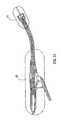
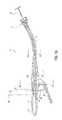
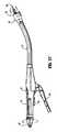
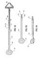
- FIG. 1is a top side perspective view from the proximal end of the presently disclosed surgical stapling device in the unapproximated position;
- FIG. 2is a top side perspective view from the distal end of the surgical stapling device shown in FIG. 1 ;
- FIG. 3is a side perspective exploded view of the handle assembly of the surgical stapling device shown in FIG. 1 ;
- FIG. 3Ais a top perspective view of the indicator of the handle assembly shown in FIG. 3 ;
- FIG. 4is a side perspective view from the top of the handle assembly of the surgical stapling device shown in FIG. 1 with a handle section removed;
- FIG. 5is a side perspective view from the bottom of the handle assembly of the surgical stapling device shown in FIG. 4 ;
- FIG. 6is a side perspective exploded view of the central body portion and distal head portion of the surgical stapling device shown in FIG. 1 ;
- FIG. 7is an enlarged side perspective of the anvil retainer and band portions of the central body portion shown in FIG. 6 ;
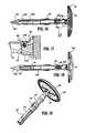
- FIG. 8is a side perspective view of the screw and screw stop of the approximation mechanism of the handle assembly shown in FIG. 5 ;
- FIG. 9is an enlarged view of the indicated area of detail shown in FIG. 3 ;
- FIG. 9Ais a side perspective view from the top of the abutment member of the handle assembly shown in FIG. 3 ;
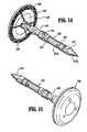
- FIG. 10is a side perspective exploded view from the proximal end of the anvil assembly of the surgical stapling device shown in FIG. 1 ;
- FIG. 11is a side perspective view of the retaining clip of the anvil assembly shown in FIG. 10 ;
- FIG. 12is a side perspective view of the distal end of the center rod of the anvil assembly shown in FIG. 10 with a removable trocar fastened thereto;
- FIG. 13is a side perspective view of the center rod and removable trocar shown in FIG. 11 separated one from the other;
- FIG. 14is a side perspective view from the proximal end of the anvil assembly shown in FIG. 10 with the removable trocar attached thereto;
- FIG. 15is a side perspective view from the distal end of the anvil assembly shown in FIG. 14 ;
- FIG. 16is a side cross-sectional view taken through the retaining clip of the anvil assembly and removable trocar of the anvil assembly shown in FIG. 15 ;
- FIG. 17is an enlarged view of the indicated area of detail shown in FIG. 16 ;
- FIG. 18is a side cross-sectional view taken through the pivot member of the anvil head assembly of the anvil assembly shown in FIG. 15 ;
- FIG. 19is a side perspective view from the proximal end of the anvil assembly shown in FIG. 18 with the removable trocar removed;
- FIG. 20is a perspective, partial cutaway view from the distal end of the anvil assembly shown in FIG. 19 , with the anvil head removed;
- FIG. 21is a side cross-sectional partial cutaway view of the distal portion of the anvil assembly shown in FIG. 19 , with the anvil head in phantom;
- FIG. 22is a side perspective view from the bottom of the screw stop of the handle assembly shown in FIG. 3 ;
- FIG. 23is a bottom perspective view from the proximal end of the screw stop shown in FIG. 22 ;
- FIG. 24is a top perspective view of the cam adjustment member of the handle assembly shown in FIG. 3 ;
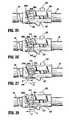
- FIG. 25is a side view of the screw and screw stop of the handle assembly shown in FIG. 3 with the set screw and the cam adjustment member removed;
- FIG. 26is a side view of the screw and screw stop shown in FIG. 25 with the set screw and cam adjustment member attached thereto;
- FIG. 27is a side view of the screw and screw stop shown in FIG. 26 with the cam adjustment screw adjusted to increase the tissue gap;
- FIG. 28is a side view of the screw and screw stop shown in FIG. 26 with the cam adjustment screw adjusted to decrease the tissue gap;
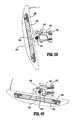
- FIG. 29is a top perspective view from the proximal end of the slide member of the indicator mechanism of the handle assembly shown in FIG. 3 ;
- FIG. 30is a bottom perspective view of the lockout member of the fire lockout mechanism of the handle assembly shown in FIG. 3 ;
- FIG. 31is a side cross-sectional view of the surgical stapling device shown in FIG. 1 with the anvil assembly removed;
- FIG. 32is a side enlarged view of the handle assembly of the surgical stapling device shown in FIG. 31 with the handle sections removed;
- FIG. 33is an enlarged view of the indicated area of detail shown in FIG. 31 ;
- FIG. 34is an enlarged, cross-sectional view of the shell assembly in the indicated area of detail shown in FIG. 31 ;
- FIG. 34Ais an enlarged, cross-sectional view of the shell assembly in the indicated area of detail shown in FIG. 31 , according to an embodiment of the present disclosure
- FIG. 34Bis a perspective view of a portion of the shell assembly of FIG. 34 ;
- FIG. 34Cis a perspective view of a portion of the shell assembly of FIG. 34A ;
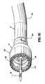
- FIG. 35is a perspective view from the front of the distal end of the surgical stapling device shown in FIG. 31 with the anvil assembly removed;
- FIG. 36is a perspective view from the front of the distal end of the surgical stapling device shown in FIG. 35 with an anvil assembly attached thereto;
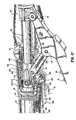
- FIG. 37is a side cross-sectional view of the distal end of the surgical stapling device shown in FIG. 36 ;
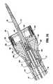
- FIG. 38is a side cross-sectional view of the surgical stapling device shown in FIG. 31 with the anvil assembly attached thereto;
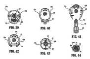
- FIG. 39is a cross-sectional view taken along section lines 39 - 39 of FIG. 38 ;
- FIG. 40is a cross-sectional view taken along section lines 40 - 40 of FIG. 38 ;
- FIG. 41is a cross-sectional view taken along section lines 41 - 41 of FIG. 38 ;
- FIG. 42is a cross-sectional view taken along section lines 42 - 42 of FIG. 38 ;
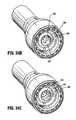
- FIG. 43is a cross-sectional view taken along section lines 43 - 43 of FIG. 38 ;
- FIG. 44is a cross-sectional view taken along section lines 44 - 44 of FIG. 38 ;
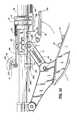
- FIG. 45is a side perspective view of the surgical stapling device shown in FIG. 38 with the anvil assembly in an approximated position;
- FIG. 46is a side cross-sectional view of the distal end of the surgical stapling device shown in FIG. 45 ;
- FIG. 47is a side enlarged view of the handle assembly of the surgical stapling device shown in FIG. 45 with a handle section removed;
- FIG. 48is a side cross-sectional view of the handle assembly of the surgical stapling device shown in FIG. 45 ;
- FIG. 49is a top horizontal cross-sectional view of a portion of the handle assembly of the surgical stapling device shown in FIG. 45 ;
- FIG. 50is a side view of a portion of the handle assembly of the surgical stapler shown in FIG. 45 with the handle sections removed;
- FIG. 51is a side cross-sectional view of a portion of the handle assembly of the surgical stapling device shown in FIG. 45 after the firing trigger has been actuated;
- FIG. 52is a side cross-sectional view of the distal end of the surgical stapling device shown in FIG. 45 after the firing trigger has been actuated;
- FIG. 53is a side view of the handle assembly shown in FIG. 51 with the handle sections removed;
- FIG. 54is an enlarged view of the firing link extension engaging the abutment member of the tactile indicator mechanism of the handle assembly shown in FIG. 53 ;
- FIG. 55is a side cross-sectional view of the distal portion of the anvil assembly of the surgical stapling device shown in FIG. 52 ;
- FIG. 56is a side cross-sectional view of the distal portion of the anvil assembly shown in FIG. 55 with a portion of the anvil head assembly in phantom;
- FIG. 57is a side view of the surgical stapling device shown in FIG. 45 after the anvil assembly and cartridge assembly have been unapproximated a distance sufficient to permit the anvil head assembly to pivot on the anvil center rod;
- FIG. 58is an enlarged view of the abutment member of the tactile indicator mechanism of the handle assembly shown in FIG. 53 (during unapproximation of the anvil and cartridge assemblies) with the wing of the screw stop, shown in phantom, in engagement with the abutment member;
- FIG. 59is a side cross-sectional view of the anvil assembly shown in FIG. 56 as the anvil head assembly begins to tilt;
- FIG. 60is a side cross-sectional view of the anvil assembly shown in FIG. 59 with the anvil assembly tilted;
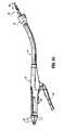
- FIG. 61is a side view of the surgical stapling device shown in FIG. 45 with the anvil head assembly unapproximated and tilted.
- FIG. 62is a side cross-sectional view of another embodiment of the presently disclosed surgical stapling device with the anvil assembly removed from the anvil retainer;
- FIG. 63is a side cross-sectional view of the surgical stapling device shown in FIG. 62 with the anvil assembly attached to the anvil retainer in the open position;
- FIG. 64is a side cross-sectional view of the anvil assembly of the surgical stapling device shown in FIG. 63 ;
- FIG. 65is a side cross-sectional view of the surgical stapling device shown in FIG. 63 with the anvil assembly in the approximated position;
- FIG. 66is a side perspective view from the proximal end of the retainer extension of the surgical stapling device shown in FIG. 65 ;
- FIG. 67is a side view of the retainer extension shown in FIG. 66 ;
- FIG. 68is a top cross-sectional view of the retainer extension shown in FIG. 67 ;
- FIG. 69is a top view of the anvil retainer of the surgical stapling device shown in FIG. 65 ;
- FIG. 70is a side view of the anvil retainer shown in FIG. 69 ;
- FIG. 71is an enlarged view of the indicated area of detail shown in FIG. 70 ;
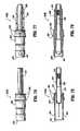
- FIG. 72is a side view of the outer housing portion of the shell assembly of the surgical stapling device shown in FIG. 65 ;
- FIG. 73is a top view of the outer housing portion of the shell assembly shown in FIG. 72 ;
- FIG. 74is a cross-sectional view taken along section lines 74 - 74 of FIG. 72 ;
- FIG. 75is a cross-sectional view taken along section lines 75 - 75 of FIG. 73 ;
- FIG. 76is a side view of the inner guide portion of the shell assembly of the surgical stapling device shown in FIG. 65 ;
- FIG. 77is a top view of the inner guide portion of the shell assembly shown in FIG. 76 ;
- FIG. 78is a side cross-sectional view of the inner guide portion of the shell assembly shown in FIG. 77 ;
- FIG. 79is a top cross-sectional view of the inner guide portion of the shell assembly shown in FIG. 77 ;
- FIG. 80is a side view of the pusher of the surgical stapling device shown in FIG. 65 ;
- FIG. 81is a top view of the pusher shown in FIG. 80 ;
- FIG. 82is a side cross-sectional view of the pusher shown in FIG. 81 ;
- FIG. 83is a top cross-sectional view of the pusher shown in FIG. 82 ;
- FIG. 84is a side cross-sectional view of the anvil assembly of the surgical stapling device shown in FIG. 65 ;
- FIG. 85is a top cross-sectional view of the anvil assembly of the surgical stapling device shown in FIG. 84 ;
- FIG. 86is a top view of the anvil center rod of the anvil assembly shown in FIG. 85 ;
- FIG. 87is a side view of the anvil center rod of the anvil assembly shown in FIG. 85 ;
- FIG. 88is a side cross-sectional view of the anvil head of the anvil assembly shown in FIG. 85 ;
- FIG. 89is a side view of the anvil head shown in FIG. 88 ;
- FIG. 90is a side cross-sectional view of the anvil center rod shown in FIG. 87 ;
- FIG. 91is a side view of the anvil cover of the anvil assembly shown in FIG. 84 ;
- FIG. 92is a side cross-sectional view of the anvil cover shown in FIG. 91 ;
- FIG. 93is a side cross-sectional view of an anvil assembly insertion handle
- FIG. 94is a side perspective view of the anvil assembly insertion handle shown in FIG. 93 ;
- FIG. 95is a side cross-sectional view of the anvil assembly insertion handle attached to the anvil assembly shown in FIG. 84 ;
- FIG. 96is a top view of a speculum suitable for use with the presently disclosed surgical stapling device
- FIG. 97is a side perspective view from above of the speculum shown in FIG. 96 ;
- FIG. 98is a rear view of the speculum shown in FIG. 96 ;
- FIG. 99is a side cross-sectional view of the speculum shown in FIG. 97 .
- proximalwill refer to the portion of the instrument closest to the operator and the term “distal” will refer to the portion of the instrument farthest from the operator.
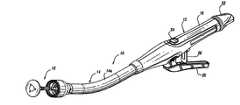
- FIGS. 1 and 2illustrate one embodiment of the presently disclosed surgical stapling device shown generally as 10 .
- surgical stapling device 10includes a proximal handle assembly 12 , an elongated central body portion 14 including a curved elongated outer tube 14 a , and a distal head portion 16 .
- proximal handle assembly 12an elongated central body portion 14 including a curved elongated outer tube 14 a
- distal head portion 16e.g., the treatment of hemorrhoids
- the length, shape and/or the diameter of body portion 14 and head portion 16may also be varied to suit a particular surgical procedure.
- Handle assembly 12includes a stationary handle 18 , a firing trigger 20 , a rotatable approximation knob 22 and an indicator 24 .
- Stationary handle 18may be formed from thermoplastic handle sections 18 a and 18 b , e.g., polycarbonate, ( FIG. 3 ) which together define a housing for the internal components of handle assembly 12 .
- Handle sections 18 a and 18 bmay be secured together by sonic welding. Alternately, other known securement techniques may be employed including screws, adhesives, snap-fit connectors, etc.
- the internal components of handle portion 12will be discussed in detail below.
- cushioned and/or resilient slip resistant portionssuch as a grip (not shown) can be fastened to or included as part of handle sections 18 a and 18 b and firing trigger 20 .
- the slip resistant gripmay be formed over handle sections 18 a and 18 b and firing trigger 20 using an overmolding procedure and may be formed from Neoprene polychloroprene or rubber. Alternately, other suitable, e.g., elastomeric, materials and joining techniques may be employed.
- a pivotally mounted trigger lock 26is fastened to handle assembly 12 and is manually positioned to prevent inadvertent firing of stapling device 10 .
- Indicator 24is positioned on the stationary handle 18 and includes indicia, e.g., color coding, alpha-numeric labeling, etc., to identify to a surgeon whether the device has been fired and/or when the device is ready to be fired.
- indiciae.g., color coding, alpha-numeric labeling, etc.
- Head portion 16includes an anvil assembly 30 and a shell assembly 31 .
- the components of surgical device 10are formed from thermoplastics including polycarbonates, and metals including stainless steel and aluminum.
- the particular material selected to form a particular componentwill depend upon the strength requirements of the particular component.
- the anvilmay be formed from a metal, such as stainless steel
- the stationary handlemay be formed from a thermoplastic such as polycarbonate.
- other materials not listed above, which can withstand sterilization proceduresmay be used to form components of stapling device 10 provided the materials are suitable for surgical use and meet the strength requirements of the particular component.
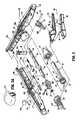
- FIGS. 3-5illustrate the internal components of handle assembly 12 .
- the internal componentsinclude the proximal components of approximation and firing mechanisms, a firing lockout mechanism and an indicator drive mechanism.
- FIGS. 6 and 7illustrate the internal components of elongated body portion 14 . These components include the distal components of the approximation and firing mechanisms. Each of these mechanisms will be disclosed in detail hereinbelow.
- the approximation mechanismincludes approximation knob 22 , a rotatable sleeve 33 , a drive screw 32 , first and second screw extensions 34 and 36 ( FIG. 6 ), and an anvil retainer 38 .
- Rotatable sleeve 33includes a substantially cylindrical hollow body portion 40 and a substantially cylindrical collar 42 which together define a central bore 33 a .
- Collar 42has an annular groove 44 formed thereabout and is dimensioned to receive an inwardly extending flange 46 formed on an inner wall of stationary handle 18 . Engagement between groove 44 and flange 46 axially fixes sleeve 33 within handle 18 while permitting rotation of sleeve 33 in relation to stationary handle 18 .
- the proximal end of body portion 40 of rotatable sleeve 33extends through an opening 18 b in the proximal end of stationary handle 18 .
- a pair of diametrically opposed elongated ribs 48are positioned on the outer surface of body portion 40 .
- Approximation knob 22includes a pair of internal slots 49 a positioned to receive ribs 48 of sleeve 33 to rotatably fix sleeve 33 to knob 22 , such that rotation of knob 22 causes concurrent rotation of sleeve 33 .
- the proximal half of screw 32includes a helical channel 50 and is dimensioned to be slidably positioned within central bore 33 a of rotatable sleeve 33 .
- the distal end of screw 32includes an annular recess 35 dimensioned to receive a seal member 37 ( FIG. 3 ) for providing a fluid tight seal between the outer surface of screw 32 and the inner surface of pusher link 74 ( FIG. 6 ).
- a pin 52( FIG. 3 ) extends radially through body portion 42 of sleeve 33 into helical channel 50 . Since sleeve 33 is axially fixed with respect to stationary handle 18 , rotation of sleeve 33 about screw 32 causes pin 52 to move along channel 50 of screw 32 to effect axial movement of screw 32 within stationary handle 18 .
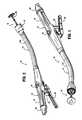
- top and bottom screw extensions 34 and 36each include a proximally located flexible flat band portion 58 and a distally located flat band portion 60 .
- screw extensions 34 and 36may have other than a band configuration.
- screw extensions 34 and 36may be semi-circular or circular in cross-section.
- the flexibility of top and bottom screw extensions 34 and 36permits movement of screw extensions 34 and 36 through curved elongated body portion 14 .
- the proximal end of each band portion 58includes a hole 62 dimensioned to receive a pin 64 for securing the proximal end of screw extensions 34 and 36 within transverse slot 54 of screw 32 .
- each band portion 58may be secured to screw 32 , e.g., welding, crimping, etc.
- Distally located band portion 60 of each screw extension 34 and 36is dimensioned to be received within a transverse slot 66 formed in a proximal end of anvil retainer 38 ( FIG. 7 ) to fasten anvil retainer 38 to the distal end of screw extensions 34 and 36 .
- a pair of pins 66 awhich extend through the proximal end of anvil retainer 38 and band portions 60 are used to secure screw extensions 34 and 36 to anvil retainer 38 .
- band portions 60can be brazed or welded within slot 66 or other fastening techniques may be used to secure band portions 60 of screw extensions 34 and 36 to anvil retainer 38 , e.g., screws, crimping, etc.
- Anvil retainer 38includes an annular protrusion 177 ( FIG. 7 ) which is configured to engage the anvil assembly in a manner to be discussed in detail below.
- protrusion 177need not be annular or may include different attachment structure, e.g., recesses, grooves, etc.
- rotatable sleeve 33is rotated about the proximal end of screw 32 to move pin 52 along helical channel 50 of screw 32 . Since sleeve 33 is axially fixed to stationary handle 18 , as pin 52 is moved through channel 50 , screw 32 is advanced or retracted within stationary handle 18 . As a result, top and bottom screw extensions 34 and 36 , which are fastened to the distal end of screw 32 , and anvil retainer 38 , which is fastened to the distal end of screw extensions 34 and 36 , are moved axially within elongated body portion 14 . Since anvil assembly 30 is secured to the distal end of anvil retainer 38 , rotation of approximation knob 22 will effect movement of anvil assembly 30 in relation to shell assembly 31 between spaced and approximated positions.
- Firing trigger 20includes a body portion 76 and a trigger cover 80 .
- a cushioned gripping surface(not shown) which may be formed of Neoprene polychloroprene or rubber is provided on trigger cover 80 .
- the cushioned gripping surfaceprovides a non-slip cushioned surface to make actuation of device 10 more comfortable and less traumatic to a surgeon.
- Body portion 76 of trigger 20is pivotally connected to a coupling member 86 (which is secured to the proximal end of pusher link 74 ), by a pivot member 84 .
- Coupling member 86may be formed integrally with pusher link 74 or as a separate element fastened thereto.
- Firing link 72has a first end pivotally secured to body portion 76 of trigger 20 by a pivot member 87 and a second end pivotally secured within a vertical slot 82 formed between stationary handle half-sections 18 a and 18 b of stationary handle 18 by pivot member 79 .
- Pivot member 79is free to move vertically within slot 82 .
- a spring 82 a( FIG. 9 ) is supported within handle 18 to urge pivot member 79 downwardly towards the bottom of slot 82 .
- Body portion 76further includes a pair of abutments including an abutment 89 and an abutment 91 which are positioned to engage the distal end 26 a ( FIG. 4 ) of trigger lock 26 in a manner to be described in greater detail below to prevent actuation of trigger 20 prior to approximation of device 10 .
- Coupling member 86which is supported on the proximal end of elongated pusher link 74 includes a flange 104 ( FIG. 6 ).
- a spring 106positioned between an inner wall or abutment within stationary handle 18 and flange 104 , biases pusher link 74 proximally to a retracted, non-fired position.
- a pair of wings 108extend radially outwardly from coupling member 86 . Wings 108 are dimensioned to slide along channel 111 ( FIG. 3 ) formed along the internal walls of stationary handle 18 to maintain proper alignment of pusher link 74 within stationary handle 18 during firing of device 10 .
- Pusher link 74includes a pair of engagement fingers 110 which are dimensioned to lockingly engage with members 220 formed in the proximal end of pusher back 186 .
- Pusher back 186forms part of shell assembly 31 and will be discussed in greater detail below.
- Pusher link 74may be formed from a flexible plastic material and includes a plurality of notches 187 which allow pusher link 74 to bend more easily as it moves through body 14 .
- Pusher link 74defines a hollow channel 75 for slidably receiving the approximation mechanism.
- a flat surface or cutout 74 a formed in pusher link 74slidably supports screw extensions 34 and 36 which are positioned in juxtaposed alignment one on top of the other.
- Spacers 77are positioned within outer tube 14 a adjacent cutout 74 a to provide additional support for screw extensions 34 and 36 and pusher link 74 and prevent each component from buckling during actuation.
- An annular channel 74 bis formed about pusher link 74 to receive an O-ring seal 74 c .
- Pusher link 74is slidably positioned within body portion 14 such that O-ring 74 c seals the space between pusher link 74 and an internal wall of outer tube 14 a . Operation of the firing mechanism of the device will be described in detail below.
- firing link 72When firing trigger 20 is actuated, i.e., pivoted about pivot member 84 , firing link 72 is moved proximally until pivot member 79 engages an abutment surface 307 ( FIGS. 25 , 28 and 48 ) formed on screw stop 306 . Screw stop 306 is axially fixed to screw 32 .
- pusher link 74When firing trigger 20 is pushed distally, pusher link 74 is advanced distally against the bias of spring 106 .
- actuation of firing trigger 20effects advancement of pusher back 186 within shell assembly 31 to eject staples from shell assembly 31 in a manner to be described below.
- anvil assembly 30includes an anvil head assembly 120 and an anvil center rod assembly 152 .
- Anvil head assembly 120includes a post 122 , an anvil head 124 , a backup plate 126 , a cutting ring 128 , an anvil 129 and a retaining clip 127 .
- Post 122is centrally positioned through a bore in anvil head 124 .
- Anvil 129is supported on anvil head 124 in an outer annular recess 136 and includes a plurality of pockets 140 for receiving and deforming staples.
- At least one tab 129 aextends radially outwardly from anvil 129 and is dimensioned to be received within a cutout 124 a formed in anvil head 124 .
- Backup plate 126includes a central opening 126 b which is positioned about post 122 within an inner recess 134 of anvil head 124 between post 122 and annular recess 136 .
- Backup ring 126includes a raised platform 126 a .
- Cutting ring 128includes an opening 128 a having a configuration substantially the same as platform 126 a . Opening 128 a is positioned about platform 126 a to rotatably fix cutting ring 128 a on backup ring 126 .
- cutting ring 128is formed from polyethylene and is fixedly secured to backup plate 126 using, for example, an adhesive.
- Backup ring 126may be formed from a harder material such as a metal. Alternately other materials of construction may be used to construct plate 126 and ring 128 . Cutting ring 128 and backup plate 126 are slidably mounted about post 122 . Backup plate 126 includes a pair of inwardly extending tabs 150 which will be described in further detail below. Cutting ring 128 includes tabs 128 b which are received within cutouts 124 b formed in anvil head 124 to properly align backup ring 126 and cutting ring 128 within anvil head 124 .
- Anvil center rod assembly 152includes anvil center rod 154 , a plunger 156 and plunger spring 158 .
- a first end of center rod 154includes a transverse throughbore 160 which is offset from the central longitudinal axis of center rod 154 .
- Post 122 of anvil head assembly 120also includes a transverse throughbore 162 .
- a pivot member 164pivotably secures post 122 to center rod 154 such that anvil head assembly 120 is pivotably mounted to anvil center rod assembly 152 .
- Plunger 156is slidably positioned in a bore 154 b ( FIG. 16 ) formed in the first end of center rod 154 .
- Plunger 156includes an engagement finger 168 which is offset from the pivot axis of anvil head assembly 120 and biased into engagement with the base 122 a of post 122 by plunger spring 158 to urge anvil head assembly 120 to a pivoted position orthogonal to center rod 154 .
- tabs 150 formed on backup plate 126engage a top surface 154 a ( FIG. 20 ) of center rod 154 to prevent anvil head assembly 120 from pivoting about pivot member 164 .
- backup plate 126 and cutting ring 128are moved deeper into anvil recess 134 of anvil head 124 about post 122 ( FIG. 21 ) by knife 188 ( FIG. 6 ) in a manner to be described in further detail below. Movement of backup plate 126 and cutting ring 128 into anvil recess 134 moves tabs 150 out of engagement with top surface 154 a of center rod 154 to permit plunger 156 to pivot anvil head assembly 120 about pivot member 164 .
- a retainer clip 127is positioned in a transverse slot 122 c formed in post 122 and includes a pair of outwardly biased flexible arms 127 a and 127 b .
- Arm 127 bincludes a recess 127 c dimensioned to receive pivot pin 164 ( FIG. 17 ).
- arms 127 a and 127 bPrior to firing device 10 , arms 127 a and 127 b are deformed inwardly by backup plate 126 ( FIG. 17 ).
- backup plate 126FIG. 17
- flexible arms 127 a and 127 bspring outwardly to a position in front of backup plate 126 . In this position, arms 127 a and 127 b prevent cutting ring 128 and backup plate 126 from sticking to knife 188 when anvil assembly 30 is unapproximated.
- a second end of center rod 154includes a bore 170 defined by a plurality of flexible arms 155 . Bore 170 is dimensioned to receive a removable trocar 157 ( FIG. 12 ).
- Flexible arms 155each include an opening 155 a dimensioned to receive a projection 157 d formed on removable trocar 157 to releasably secure trocar 157 to center rod 154 ( FIG. 13 ).
- the distal ends of each of flexible arms 155include an internal shoulder 155 b dimensioned to releasably engage anvil retainer 38 ( FIG. 6 ) in a manner to be discussed in detail below.
- a plurality of splines 181FIG.
- Center rod 154also includes an annular recessed portion 183 to facilitate grasping of anvil assembly 30 by a surgeon with a grasper.
- removable trocar 157includes a trocar tip 157 a , a body portion 157 b and a cantilevered arm 157 c .
- Projection 157 dis positioned on the end of cantilevered arm 157 c .
- Arm 157 cis deflectable downwardly, i.e., radially inwardly, in the direction indicated by arrow “A” in FIG. 13 to facilitate insertion of body portion 157 b into bore 170 of center rod 154 .
- Splines 157 eare provided on body portion 157 b to properly align trocar 157 within bore 170 of center rod 154 .
- Arm 157 cbiases projection 157 d outwardly such that when projection 157 d passes beneath opening 155 a in center rod 154 , projection 157 d snaps into opening 155 a to releasably secure removable trocar 157 to center rod 154 .
- a tab 157 fis positioned on arm 157 c and can be depressed to facilitate removal of trocar 157 from center rod 154 .
- Trocar tip 157 aincludes a throughbore 157 g dimensioned to receive a suture (not shown) to facilitate locating and removal of trocar 157 within and from the human body. Although illustrated as having a sharpened tip, other trocar tip configurations are envisioned, e.g., blunt.
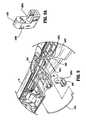
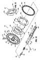
- shell assembly 31includes a shell 182 , a pusher back 186 , a cylindrical knife 188 , and a staple guide 192 .
- Shell 182includes an outer housing portion 194 and an inner guide portion 196 having grooves 196 a for mating with splines 181 on anvil center rod 154 ( FIG. 10 ).
- Outer housing portion 194defines a throughbore 198 having a distal cylindrical section 200 , a central conical section 202 and a proximal smaller diameter cylindrical section 204 .
- a plurality of openings 206may be formed in conical section 202 . Openings 206 are dimensioned to permit fluid and tissue passage during operation of the device.
- a pair of diametrically opposed flexible engagement members 207are formed on proximal cylindrical section 204 of shell 182 .
- Engagement members 207are positioned to be received in openings 207 a formed on the distal end of outer tube 14 a to secure shell 182 to elongated body 14 .
- a pair of openings 211 formed in the proximal end of outer tube 14 aare dimensioned to receive protrusions (not shown) formed on the internal wall of stationary handle 18 ( FIG. 1 ) to facilitate attachment of tube 14 a to handle portion 12 .
- pusher back 186includes a central throughbore 208 which is slidably positioned about inner guide portion 196 of shell 182 .
- Pusher back 186includes a distal cylindrical section 210 which is slidably positioned within distal cylindrical section 200 of shell 182 , a central conical section 212 and a proximal smaller diameter cylindrical section 214 .
- the proximal end of pusher back 186includes members 220 which are configured to lockingly engage with resilient fingers 110 of pusher link 74 to fasten pusher link 74 to pusher back 186 such that a distal face of pusher link 74 abuts a proximal face of pusher back 186 .
- the distal end of pusher back 186includes a pusher 190 .
- Pusher 190includes a multiplicity of distally extending fingers 226 dimensioned to be slidably received within slots 228 formed in staple guide 192 to eject staples 230 therefrom.
- Cylindrical knife 188is frictionally retained within the central throughbore of pusher back 186 to fixedly secure knife 188 in relation to pusher 190 .
- knife 188may be retained within pusher back 186 using adhesives, crimping, pins, etc.
- the distal end of knife 188includes a circular cutting edge 234 .
- pusher back 186is advanced distally within shell 182 . Advancement of pusher back 186 advances fingers 226 through slots 228 of staple guide 192 to advance staples 230 positioned within slots 228 and eject staples 230 from staple guide 192 into staple deforming pockets 140 of anvil 129 ( FIG. 11 ). Since knife 188 is secured to pusher back 186 , knife 188 is also advanced distally to core tissue as will be described in more detail below.
- a rigid bushing 209is supported in the proximal end of inner guide portion 196 of shell 182 .
- Bushing 209defines a throughbore dimensioned to slidably receive anvil retainer 38 and center rod 154 ( FIG. 10 ) of anvil assembly 30 .
- Bushing 209provides lateral support for flexible arms 155 of center rod 154 when the anvil assembly 30 has been approximated to prevent disengagement of anvil assembly 30 from anvil retainer 38 .
- flexible arms 155 of center rod 154are positioned externally of bushing 209 to permit removal of anvil assembly 30 from retainer 38 .
- Shell assembly 31is illustrated in FIGS. 34A and 34C .
- a raised boss 197is disposed adjacent a distal end of inner guide portion 196 and is preferably integrally formed with inner guide portion 196 .
- Raised boss 197is preferably a circumferential extension of inner guide portion 196 and is configured to reduce the possibility of tissue becoming caught between pusher back 186 and inner guide portion 196 upon retraction of pusher back 186 .
- raised boss 197is configured to shroud slots 199 ( FIGS. 34 and 34B ) in pusher back 186 .
- distal end 197 a of raised boss 197is substantially aligned with a distal end 186 a of pusher back 186 when pusher back 186 is in a retracted position ( FIG. 45 ).
- so-called “tissue donuts”may form when tissue enters into portion of slots 199 in pusher back 186 that extend beyond limits of inner guide portion 196 upon retraction of pusher back 186 .
- raised boss 197is configured to help direct purse-stringed tissue away from pusher back 186 and towards a center of inner guide portion 196 , which may be facilitated by a tapered portion 197 b (see FIG. 34A ) disposed on at least one of inner guide portion 196 and raised boss 197 . It is envisioned that raised boss 197 extends inner guide portion 196 between about 0.110 inches and about 0.114 inches, e.g., about 0.120 inches, although other dimensions are also contemplated.
- a cam adjustment member 400is secured by set screw 312 onto a sidewall 306 a of screw stop 306 within a recess 306 b formed in sidewall 306 a .
- Cam adjustment member 400includes a circular disc 402 having a throughbore 404 .
- Throughbore 404is eccentrically formed through disc 402 and is dimensioned to receive set screw 312 .
- a smaller notch or hole 406is also formed in disc 402 and is dimensioned to receive the tip of an adjustment tool (not shown).
- Recess 306 b( FIG. 22 ) includes a forward abutment shoulder or surface 306 c ( FIG. 23 ) and a rear abutment surface 306 d and is dimensioned to receive disc 402 such that the outer edge of disc 402 abuts forward and rear abutment surfaces 306 c and 306 d.
- Set screw 312extends through disc 402 and screw stop 306 and is received in a threaded bore 32 a in screw 32 to secure screw stop 306 in position on screw 32 .
- Cam adjustment member 400functions to adjust the axial position of screw stop 306 on screw 32 . More specifically, set screw 312 can be loosened to allow disc 402 to rotate within recess 306 b of screw stop 306 while still remaining fixed to screw 32 . Since disc 402 is eccentrically mounted about screw 32 and engages forward and rear abutment surfaces 306 c and 306 d of recess 306 b , rotation of disc 402 about fixed set screw 312 will urge screw stop 306 axially along screw 32 to adjust the axial position of screw stop 306 on screw 32 .
- stapling device 10When stapling device 10 is in a fully approximated position (as can be seen for instance in FIG. 65 ), i.e., anvil assembly 30 , 640 and shell assembly 31 , 605 are brought into juxtaposed alignment to define a tissue receiving clearance, screw stop 306 ( FIG. 47 ) abuts against body portion 42 of the rotatable sleeve 33 , i.e., sleeve 33 functions as a stop for the approximation mechanism. In this position, anvil assembly 30 and shell assembly 31 are spaced slightly to define a tissue receiving clearance. By providing cam adjustment member 400 , the tissue receiving clearance can be selectively adjusted to be within a desired range by adjusting the position of screw stop 306 on screw 32 .
- cam adjustment member 400permits adjustment of the tissue receiving clearance of ⁇ 0.045 inches, although greater or lesser adjustment capabilities are also envisioned. Typically, adjustments to the tissue receiving clearance will be made by the device manufacturer. Alternately, a hole or opening (not shown) may be provided in handle portion 12 ( FIG. 1 ) to provide direct access to adjustment member 400 to allow for adjustment of the tissue receiving clearance at the surgical site.
- the indicator mechanismincludes indicator 24 , lens cover 24 a and slide member 500 .
- Indicator 24is pivotally supported about a pivot member 502 which may be formed monolithically with handle sections 18 a and 18 b .
- Lens cover 24 ais positioned above indicator 24 and may be formed of magnification material to facilitate easy visualization of indicator 24 .
- Slide member 500( FIG. 29 ) includes a body portion 504 having an elongated slot 506 formed therein, a distal abutment member or upturned lip portion 508 , and a proximal extension 510 .
- Slide member 500is slidably positioned between handle sections 18 a and 18 b .
- Proximal extension 510is slidably supported within stationary handle 18 by support structure 516 ( FIG. 5 ).
- a biasing member 512e.g., a coil spring, is positioned in compression about proximal extension 510 between support structure 516 and body portion 504 of slide member 500 to urge slide member 500 distally within stationary handle 18 .
- Indicator 24includes a pair of downwardly extending projections 518 and 520 positioned about pivot member 502 . Upturned lip portion 508 of slide member 500 is positioned between projections 518 and 520 and is positioned to engage projections 518 and 520 as it moves within stationary handle 18 .
- biasing member 512urges slide member 500 distally to move lip portion 508 into engagement with projection 518 to pivot indicator to a first position, which provides indication to a surgeon that the device has not been approximated and is not in a fire-ready condition.
- Screw stop 306is fixedly attached to screw 32 .
- Screw stop 306includes a first engagement member 522 which is positioned to travel through slot 506 and engage the proximal end 506 a of slot 506 during approximation of the device.
- engagement member 522abuts proximal end 506 a ( FIG. 29 ) of slot 506
- further approximation of device 10moves slide plate 500 proximally within stationary handle 18 against the bias of spring 512 such that upturned lip 508 of slide member 500 engages projections 518 & 520 of indicator 24 .
- Engagement between projections 518 & 520 and lip 508causes indicator 24 to pivot about pivot member 502 to a second position. In the second position, indicator 24 provides indication to a surgeon that the device has been approximated and is now in a fire-ready position.
- the firing-lockout mechanismincludes trigger lock 26 and lockout member 530 .
- Trigger lock 26is pivotally supported within bores 532 in handle sections 18 a and 18 b about pivot member 534 .
- pivot member 534extends from an upper edge of trigger lock 26 and is T-shaped and frictionally engages the inner wall of bores 532 to prevent free rotation of trigger lock 26 .
- Tip 26 a ( FIG. 5 ) of trigger lock 26is positioned between abutments 89 and 91 on body portion 76 of firing trigger 20 to prevent actuation of trigger 20 when trigger lock 26 is in the locked position.
- Trigger lock 26also includes a proximal extension 26 b ( FIG. 4 ) which will be discussed in further detail below.
- Lockout member 530( FIG. 30 ) includes a body portion 536 , a proximal extension 538 , a pair of front legs 540 a , a pair of rear legs 540 b , and an abutment member or downturned lip portion 542 .
- Lockout member 530is slidably positioned between first and second stops 544 and 546 ( FIG. 5 ) formed on an internal wall of handle sections 18 a and 18 b .
- Stop 544is positioned to engage rear legs 540 b and stop 546 is positioned to engage front legs 540 a . It is also envisioned that a single abutment member may be substituted for each pair of legs.
- a biasing member 548e.g., a coil spring, is positioned between stop 544 and body 536 about proximal extension 538 to urge lockout 530 to its distal-most position with legs 540 a abutting stop 546 .
- extension 26 b of trigger lock 26is positioned beneath lip portion 542 of lockout member 530 to prevent pivotal movement of trigger lock 26 , and thus prevent actuation of stapling device 10 .
- screw stop 306is secured to screw 32 .
- a second engagement member or members 548extend downwardly from screw stop 306 . (See FIG. 22 ).
- engagement member 548abuts front legs 540 a of lockout member 530 to move lockout member 530 proximally against the bias of member 548 to a position in which lip portion 542 is spaced proximally of extension 26 b of trigger lock 26 .
- trigger lock 526can be pivoted to permit firing of stapling device 10 .
- a tactile indicator mechanism provided in stationary handle 18includes an abutment member 580 which is slidably positioned in a vertical slot 582 defined within handle sections 18 a and 18 b .
- Abutment member 580includes a protuberance 580 a and a guide rib 580 b .
- Protuberance 580 ais dimensioned to be received within one of two detents 582 a and 582 b formed along a wall of slot 582 .
- Abutment member 580is movable from a retracted (downward) position, wherein protuberance 580 a is positioned within detent 582 a , to an extended (upward) position, wherein protuberance 580 a is positioned within detent 582 b . Engagement between protuberance 580 a and detents 582 a and 582 b retains abutment member 580 in the respective position.
- Detent 582 cformed in vertical slot 582 , is sized to slidably receive guide rib 580 b and thereby maintain member 580 in contact with slot 582 .
- abutment member 580Prior to firing of stapling device 10 , abutment member 580 is located in the retracted (downward) position ( FIG. 5 ). When device 10 is fired, an extension 590 of firing link 72 engages abutment member 580 and moves abutment member 580 from its retracted to its extended position. In the extended position, abutment member 580 extends into channel 111 of stationary handle 18 .
- Screw stop 306includes a pair of wings 584 which are slidably positioned in channel 111 of stationary handle 18 . After stapling device 10 has been fired, abutment member 580 is positioned within channel 111 . During unapproximation of anvil assembly 150 and cartridge assembly 31 , one of the wings 584 of screw stop 306 engage abutment member 580 when the device has been unapproximated a sufficient distance to allow anvil assembly 30 to pivot to its reduced profile position (as will be discussed in mere detail below and as can be seen in FIG. 57 ).
- abutment member 580 and wing 584 of screw stop 306provides a tactile and/or an audible indication to the surgeon that the anvil assembly 120 has tilted and stapling device 10 can be removed from a patient. If the surgical stapling device is unapproximated further, wing 584 will force abutment member 580 from the extended position back to the retracted position.
- FIGS. 31-35illustrate surgical stapling device 10 in the unapproximated or open position prior to attachment of anvil assembly 30 to anvil retainer 38 .
- biasing member 106is engaged with coupling 86 to urge pusher link 74 to its proximal-most position in which coupling 86 abuts screw-stop 306 .
- Biasing member 512is engaged with slide member 500 of the indicator mechanism to position slide member 500 in engagement with projection 518 of indicator 24 to pivot indicator 24 in a clockwise direction, as viewed in FIG. 33 .
- Biasing member 549is engaged with body 536 of lockout member 530 to urge lockout member 530 to its distal-most position, wherein lip portion 542 of lockout member 530 is positioned above extension 26 b of trigger lock 26 to prevent movement of trigger lock 26 to the unlocked position.
- Biasing member 82 aengages pivot member 79 to urge pivot member 79 to the base of vertical slot 82 .
- Tactile indicator 580is in the retracted or downward position with protrusion 580 a positioned with detent 582 a.
- FIGS. 36-44illustrate surgical stapling device 10 with anvil assembly 30 attached to anvil retainer 38 and the anvil assembly 30 in the unapproximated or open position.
- anvil retainer 38is positioned within bore 170 of center rod 154 of anvil assembly 30 .
- Flexible arms 155deflect outwardly to accommodate center rod 154 .
- Center rod 154is advanced onto anvil retainer 38 in the direction indicated by arrow “K” in FIG. 37 until internal shoulder 155 b of flexible arms 155 passes over annular protrusion 177 formed on anvil retainer 38 .
- resilient legs 155releasably engage the anvil retainer.
- the position of the remaining components of stapling deviceare unaffected by attachment of anvil assembly 30 to anvil retainer 38 and remain as described above and shown in FIGS. 31-35 .
- FIGS. 45-50illustrate surgical stapling device 10 during movement of anvil assembly 30 and cartridge assembly 31 to the approximated or closed position.
- anvil assembly 30is moved to the approximated or closed position by rotating rotation knob 22 in the direction indicated by arrow “L” in FIG. 45 .
- Rotation of knob 22causes cylindrical sleeve 33 to rotate to move pin 52 along helical channel 50 of screw 32 .
- Movement of pin 52 ( FIG. 48 ) along helical channel 50causes screw 32 to translate within sleeve 33 .
- the distal end of screw 32is connected to screw extensions 34 and 36 which are fastened at their distal ends to anvil retainer 38 .
- screw stop 306( FIG. 47 ) is axially fixed to screw 32 by set screw 312 .
- screw stop 306is moved from a distal position within stationary handle 18 to a proximal position.
- first engagement member 522 formed on screw stop 306abuts proximal end 506 a of slot 506 of slide plate 500 and moves slide plate 500 proximally against the bias of spring 512 .
- lip 508 of slide member 500engages projections 518 & 520 of indicator 24 to pivot indicator 24 in a counter-clockwise direction as viewed in FIG. 48 .
- Screw stop 306also includes a second engagement member 548 ( FIG. 47 ). As screw stop 306 is moved from the distal position to the proximal position during approximation of anvil assembly 30 , second engagement member 548 engages distal legs 540 a of lockout member 530 to move lockout member 530 proximally to a position in which lip portion 542 is spaced proximally of extension 26 b of trigger lock 26 . In this position, trigger lock 26 can be pivoted to an unlocked position to permit firing of stapling device 10 .
- Abutment surface 307comprises a substantially concave surface which is positioned to partially capture and act as a backstop for pivot 79 during firing of the stapling device.
- FIGS. 51-56illustrate surgical stapling device 10 during the firing stroke of firing trigger 20 .
- trigger 20is compressed towards stationary handle 18 (as shown by the arrow in FIG. 51 )
- pivot member 79engages abutment surface 307 on screw stop 306 and firing trigger 20 is pushed distally.
- the distal end of firing trigger 22is connected through coupling member 86 to the proximal end of pusher link 74 .
- pusher link 74is moved distally to effect advancement of pusher back 186 within shell assembly 31 .
- Fingers 190 of pusher back 186engage and eject staples 230 from staple guide 192 ( FIG. 52 ).
- Cylindrical knife 188is moved concurrently with pusher back 186 such that knife 188 moves into engagement with cutting ring 128 and backup plate 126 .
- cutting ring 128may be formed from polyethylene and backup plate 126 may be formed from a metal.
- knife 188engages cutting ring 128 , it cuts into cutting ring 128 and pushes backup plate 126 deeper into anvil head 124 to move tabs 150 from engagement with top surface 154 a of center rod 154 ( FIG. 56 ).
- Anvil head 124is now free to pivot about member 164 and is urged to do so by plunger 156 .
- wing 584 of screw stop 306engages tactile indicator 580 ( FIG. 58 ) at the point of unapproximation at which anvil assembly 124 is able to pivot to its tilted reduced profile position.
- tactile indicator 580FIG. 58
- Contact between wing 584 and tactile indicator 580provides a tactile and/or audible indication that anvil head 124 has tilted.
- wing 584 of screw stop 306will force tactile indicator to the retracted position to allow stapling device 10 to move to the fully open position. In this position, flexible arms 155 are positioned distally of bushing 209 and anvil assembly 30 can be disengaged from anvil retainer 28 .
- FIGS. 62-91illustrate another embodiment of the presently disclosed surgical stapling device shown generally as 600 .
- Stapling device 600is configured and dimensioned to be particularly suitable for use in surgical procedures for removing internal hemorrhoids from a patient.
- surgical stapling device 600includes a proximal handle assembly 601 , a central body portion 603 and a distal head portion 605 .
- the handle assembly 601is substantially identical to handle assembly 12 of surgical stapling device 10 and will not be discussed in further detail herein.
- the approximation mechanism of surgical stapling device 600includes an approximation knob 602 , a rotatable sleeve 604 , a drive screw 606 , a retainer extension 608 , and an anvil retainer 610 .
- Approximation knob 602 , rotatable sleeve 604 and drive screw 606are substantially identical to the like named components described above with respect to surgical stapling device 10 and will not be described in further detail herein.
- retainer extension 608includes a proximal end 612 defining a bore 614 dimensioned to receive the distal end of drive screw 606 .
- a pair of transverse openings 618extend through sidewalls of the proximal end of retainer extension 608 to facilitate attachment of retainer extension 608 to the distal end of drive screw 606 with a pin or screw 620 ( FIG. 62 ).
- other known attachment devicesmay be used, e.g., welding, brazing, screw threads, etc.
- the distal end of retainer extension 608includes a flat finger 622 configured to be received within a slot 624 ( FIG. 69 ) formed in the proximal end of anvil retainer 610 . Openings 626 and 626 a in retainer extension 608 and anvil retainer 610 ( FIG. 70 ), respectively, are dimensioned to receive pins or screws 628 ( FIG. 62 ) to secure anvil retainer 610 to the distal end of retainer extension 608 .
- other attachment configurations and techniquesare contemplated.
- annular shoulder 632defines an angle of about ninety-degrees with respect to the outer axial surface 610 a of anvil retainer 610 ( FIG. 71 ). As will be discussed in further detail below, the sharp angle of shoulder 632 securely fastens an anvil assembly onto anvil retainer 610 . As discussed above with respect to stapling device 10 , when approximation knob 602 ( FIG. 71 ), when approximation knob 602 ( FIG.
- anvil assembly 640( FIG. 64 ) is secured to anvil retainer 610 . Accordingly, when approximation knob 602 is manually rotated, anvil assembly 640 will move axially with anvil retainer 610 in relation to a shell assembly 642 between spaced and approximated positions.
- distal head portion 605( FIG. 63 ) includes anvil assembly 640 and shell assembly 642 .
- Shell assembly 642includes a housing 644 , a pusher 646 , a cylindrical knife 645 and a staple guide 648 .
- housing 644includes an outer housing portion 644 a and an inner guide portion 644 b .
- Outer housing portion 644 a( FIGS. 72-75 ) defines an outwardly diverging throughbore 650 and includes a small diameter proximal end 652 and a large diameter distal end 654 .
- Distal end 652includes a pair of diametrically opposed spring tabs 656 for releasably engaging inner guide portion 644 b in a manner to be discussed below.
- Throughbore 650is dimensioned to slidably receive pusher 646 ( FIG. 62 ). Because of the configuration of throughbore 650 and pusher 646 , pusher 646 is slidable in throughbore 650 only in a distal direction.
- a pair of stabilizing ribs 653( FIG. 75 ) extend inwardly from an inner wall defining throughbore 650 . Stabilizing ribs 653 engage ribs 654 ( FIG. 76 ) formed on sidewalls of inner guide portion 644 b to secure inner guide portion 644 b within outer housing portion 644 a.
- Inner guide portion 644 b( FIGS. 76-79 ) includes a cylindrical proximal end 658 , a cylindrical central portion 660 and an inner distal portion 662 .
- Proximal end 658includes a pair of openings 664 for engaging spring tabs (not shown) formed on handle assembly 612 for securing shell assembly 642 onto handle assembly 612 .
- Ribs 654are formed on inner distal portion 662 of inner guide portion 644 b .
- a pair of annular ribs 666are formed in spaced relation on central portion 660 .
- Spring tabs 656 of outer housing portion 644 a( FIGS.
- Inner distal portion 662defines a cylindrical bore 668 for slidably receiving retainer extension 608 and anvil retainer 610 ( FIG. 62 ).
- Cylindrical bore 668includes an annular array of ribs and grooves 676 for accurately circumferentially and axially aligning anvil assembly 640 and shell assembly 642 during approximation thereof.
- the proximal end of distal portion 662extends proximally within central portion 660 to define therewith a pair of channels 670 ( FIG. 78 ).
- a proximal portion of channels 670is dimensioned to slidably receive drive arms of a pusher link (not shown).
- the pusher link employed in this embodimentis similar to pusher link 74 discussed above with respect to stapling device 10 and will not be discussed in further detail herein.
- pusher 646is slidably positioned within shell assembly housing 644 .
- Pusher 646includes a pair of proximal extensions 676 which extends through the distal end of channels 670 ( FIG. 78 ) formed in inner guide portion 644 b .
- the distal end of pusher 646includes a multiplicity of distally extending fingers 680 which are slidably received within slots formed in staple guide 648 ( FIG. 62 ).
- Staple guide 648is fixedly retained in the distal end of outer housing portion 644 a . Staples (not shown) are housed within the staple guide slots (not shown).
- a cylindrical knife 645( FIGS. 62 and 63 ) is secured or frictionally retained within a central throughbore of pusher 646 .
- the distal end of knife 645includes an annular cutting edge 682 .
- the distal portion of pusher 646defines an internal chamber 780 for receiving excised tissue.
- anvil assembly 640includes an anvil head assembly 684 and an anvil center rod 686 .
- Anvil head assembly 684includes an anvil head 688 , an anvil post 690 , an anvil 692 and an anvil cover 694 .
- Anvil cover 694( FIGS. 91 and 92 ) is substantially conical and includes a rounded distal portion 696 to facilitate smooth entry of anvil assembly 640 into a body lumen or orifice, e.g., anus.
- Anvil 692is secured to anvil head 688 and includes a plurality of staple deforming pockets (not shown), as discussed above, for receiving and deforming staples.
- Anvil head assembly 684is secured to the distal end of anvil center rod 686 .
- anvil head assembly 684may be pivotally secured to anvil center rod 686 , as discussed above, in one embodiment, anvil head assembly 684 is fixedly secured to anvil center rod 686 .
- anvil center rod 686defines a central bore 700 which is partially defined by a plurality of flexile arms 702 .
- Central bore 700extends substantially along the longitudinal length of center rod 686 .
- the distal end of each flexible arm 702includes a radial projection 702 a .
- Central bore 700is dimensioned to slidably receive anvil retainer 610 ( FIG. 62 ) including distal extension 630 such that radial projections 702 a snap over and engage annular shoulder 632 ( FIGS. 70 and 71 ) of anvil retainer 610 to secure anvil assembly 640 to anvil retainer 610 .
- Radial projection 702 aFIG.
- distal extension 630 of anvil retainer 610extends through central bore 700 along a substantial portion of the length of anvil center rod 686 . In one embodiment, distal extension 630 extends through central bore 700 substantially the entire length of anvil center rod 686 .
- approximation knob 602( FIG. 63 ) is manually rotated to move screw 606 proximally, anvil retainer 610 and anvil assembly 640 are withdrawn into shell assembly 642 to move anvil head assembly 684 into approximation with shell assembly 642 ( FIG. 65 ).
- flexible arms 702are drawn into cylindrical bore 668 of inner guide portion 644 b , arms 702 are prevented from flexing outwardly to lock anvil assembly 640 to anvil retainer 610 .
- stapling device 600is particularly suitable for use in surgical procedures for removing internal hemorrhoids from a patient.
- anvil assembly 640FIG. 64
- an insertion handle 720may be used to facilitate insertion of anvil assembly 640 into the anus and rectum.
- handle 720includes a gripping knob 722 , a rigid shaft 725 extending distally from knob 722 and an attachment portion 724 .
- Attachment portion 724includes a detent 726 and a protrusion 728 .
- Attachment portion 725 of shaft 724is dimensioned to be slidably received within anvil center rod central bore 700 .
- Detent 726is positioned to be received within one of a plurality of suture holes 730 ( FIG. 87 ) formed in the distal end of anvil center rod 686 to releaseably lock handle 720 to anvil center rod 686 .
- Protrusion 728is positioned to be slidably received between and engaged by flexible arms 702 to properly align handle 720 with anvil center rod 686 .
- a stop member 728 amay also be provided on the attachment portion to limit the insertion depth of shaft 724 into central bore 700 .
- a force sufficient to flex flexible arms 702 outwardlymust be applied to handle 720 to release detent 726 from suture hole 730 .
- a purse string sutureis placed into each of the internal hemorrhoids. Thereafter, the purse string is cinched about the anvil center rod 686 to draw the internal hemorrhoids inwardly about the anvil center rod 686 .
- the purse string suturemay be placed into the internal hemorrhoids prior to insertion of the anvil assembly into the anus and rectum.
- an anoscope or speculum 750may be provided to place the purse string into the internal hemorrhoids.
- Speculum 750may include a semi-cylindrical body 752 having a tapered or blunt tip 754 .
- Body 752defines a channel or recess 756 .
- the proximal end of body 752has a semi-annular flange 758 including a plurality of openings 760 and a pair of protruding finger tabs 762 .
- speculum 750may be formed from a clear plastic material to enhance visualization. Further, the speculum 750 may include gradation markings (not shown) along the surface of the speculum 750 to assist the surgeon with knowledge of depth of placement of the hemorrhoids.
- blunt tip 754 of speculum 750is inserted into the anus to a position in which first internal hemorrhoids hang into channel 756 .
- a purse string sutureis placed into a first portion of internal hemorrhoids.
- Speculum 750is then rotated using finger tabs 762 and openings 760 until a second portion of internal hemorrhoids hang into channel 756 .
- a purse string sutureis placed into the second internal hemorrhoids. This process is repeated until a purse string suture has been placed into each of the internal hemorrhoids about the annulus of the anus.
- speculum 750is removed from the anus and the anvil assembly 640 is inserted into the anus and rectum. Thereafter, the purse string sutures are cinched to draw the internal hemorrhoids in about the anvil center rod 686 .
- Attachment structuresuch as openings, grooves, hooks, ridges or ribs, may be provided on anvil center rod 686 to secure the purse string suture and, thus, the internal hemorrhoids to the anvil center rod 686 .
- the attachment structuremay be in the form of an axially adjustable member, e.g., slidable hook, which may be adjusted to change the position of the purse string suture on anvil center rod 686 and within shell assembly 642 .
- gradationscan be placed on the center rod 686 to indicate depth of insertion of the center rod 686 or length of the suture or of sutured hemorrhoids.
- center rod 686is attached to anvil retainer 610 in the manner discussed above.
- Distal extension 630 and anvil center rod 686should be of a length to allow telescoping of extension 630 within anvil center rod 686 before visibility of the surgical site is obstructed by shell assembly 642 of device 600 .
- the combined length of anvil center rod 686 and retainer extension 630is at least 4.5 inches (114.3) or of a length to achieve the above objective.
- knob 602can be manually rotated to approximate the anvil and shell assemblies and draw the internal hemorrhoids into an inner chamber 780 ( FIG. 62 ) defined within pusher 646 and within annular knife 682 of shell assembly 642 .
- Firing trigger 790FIG. 62
- stapling device 600is removed from the anus with the excised internal hemorrhoids contained within inner chamber 780 of shell assembly 642 .
- instrument accessoriesmay be used to assist in performing particular steps of the above described procedures.
- an anal dilatormay be inserted into the anus prior to performing the above-described method steps to provide easier access to the surgical site.
- An obturatormay be used to assist in placement of the dilator.
- an expandable introducermay be provided to reduce the trauma that results from insertion of the stapling device into the anus.
- any combination of the components discussed above including the stapling device, anvil assembly, insertion handle, speculum anal dilator, and/or an obturatormay be included in a kit to perform a hemorrhoidal treatment procedure.
Landscapes
- Health & Medical Sciences (AREA)
- Life Sciences & Earth Sciences (AREA)
- Surgery (AREA)
- Heart & Thoracic Surgery (AREA)
- Engineering & Computer Science (AREA)
- Biomedical Technology (AREA)
- Nuclear Medicine, Radiotherapy & Molecular Imaging (AREA)
- Medical Informatics (AREA)
- Molecular Biology (AREA)
- Animal Behavior & Ethology (AREA)
- General Health & Medical Sciences (AREA)
- Public Health (AREA)
- Veterinary Medicine (AREA)
- Surgical Instruments (AREA)
Abstract
Description
Claims (7)
Priority Applications (1)
| Application Number | Priority Date | Filing Date | Title |
|---|---|---|---|
| US13/195,207US8317075B2 (en) | 2008-01-09 | 2011-08-01 | Raised boss for staple guide |
Applications Claiming Priority (3)
| Application Number | Priority Date | Filing Date | Title |
|---|---|---|---|
| US1988308P | 2008-01-09 | 2008-01-09 | |
| US12/348,953US8011554B2 (en) | 2008-01-09 | 2009-01-06 | Raised boss for staple guide |
| US13/195,207US8317075B2 (en) | 2008-01-09 | 2011-08-01 | Raised boss for staple guide |
Related Parent Applications (1)
| Application Number | Title | Priority Date | Filing Date |
|---|---|---|---|
| US12/348,953ContinuationUS8011554B2 (en) | 2008-01-09 | 2009-01-06 | Raised boss for staple guide |
Publications (2)
| Publication Number | Publication Date |
|---|---|
| US20110284617A1 US20110284617A1 (en) | 2011-11-24 |
| US8317075B2true US8317075B2 (en) | 2012-11-27 |
Family
ID=40843764
Family Applications (2)
| Application Number | Title | Priority Date | Filing Date |
|---|---|---|---|
| US12/348,953Active2029-06-06US8011554B2 (en) | 2008-01-09 | 2009-01-06 | Raised boss for staple guide |
| US13/195,207Expired - Fee RelatedUS8317075B2 (en) | 2008-01-09 | 2011-08-01 | Raised boss for staple guide |
Family Applications Before (1)
| Application Number | Title | Priority Date | Filing Date |
|---|---|---|---|
| US12/348,953Active2029-06-06US8011554B2 (en) | 2008-01-09 | 2009-01-06 | Raised boss for staple guide |
Country Status (1)
| Country | Link |
|---|---|
| US (2) | US8011554B2 (en) |
Cited By (3)
| Publication number | Priority date | Publication date | Assignee | Title |
|---|---|---|---|---|
| CN103961162A (en)* | 2014-05-22 | 2014-08-06 | 无锡市神康医疗器械设备有限公司 | Circumcision assembly of one-time circumcision stapler |
| WO2014139467A1 (en)* | 2013-03-15 | 2014-09-18 | Covidien Lp | Surgical stapling apparatus with reusable components |
| EP2823771A1 (en) | 2013-07-09 | 2015-01-14 | Covidien LP | Surgical device and surgical adapters for use between surgical handle assembly and surgical loading units |
Families Citing this family (179)
| Publication number | Priority date | Publication date | Assignee | Title |
|---|---|---|---|---|
| JP5070300B2 (en) | 2007-03-07 | 2012-11-07 | コヴィディエン・アクチェンゲゼルシャフト | Mucosal resection stapler |
| US8231042B2 (en) | 2008-11-06 | 2012-07-31 | Tyco Healthcare Group Lp | Surgical stapler |
| US8281974B2 (en) | 2009-01-14 | 2012-10-09 | Tyco Healthcare, Group LP | Surgical stapler with suture locator |
| US8146790B2 (en) | 2009-07-11 | 2012-04-03 | Tyco Healthcare Group Lp | Surgical instrument with safety mechanism |
| US8733615B2 (en)* | 2011-05-19 | 2014-05-27 | Ethicon Endo-Surgery, Inc. | Circular stapler with frictional reducing member |
| US8708212B2 (en) | 2011-10-18 | 2014-04-29 | Covidien Lp | Tilt top anvil with torsion spring |
| US9016547B2 (en) | 2011-10-26 | 2015-04-28 | Covidien Lp | EEA tilt top anvil with ratchet/locking mechanism |
| US8740036B2 (en) | 2011-12-01 | 2014-06-03 | Covidien Lp | Surgical instrument with actuator spring arm |
| US9186148B2 (en)* | 2012-01-05 | 2015-11-17 | Ethicon Endo-Surgery, Inc. | Tissue stapler anvil feature to prevent premature jaw opening |
| US9010605B2 (en) | 2012-01-12 | 2015-04-21 | Covidien Lp | Sliding sleeve for circular stapling instrument reloads |
| US10299815B2 (en) | 2012-01-19 | 2019-05-28 | Covidien Lp | Surgical instrument with clam releases mechanism |
| US9038882B2 (en) | 2012-02-03 | 2015-05-26 | Covidien Lp | Circular stapling instrument |
| US9022274B2 (en) | 2012-02-15 | 2015-05-05 | Covidien Lp | Circular stapler with increased lumen diameter |
| CN102551833B (en)* | 2012-02-22 | 2013-07-31 | 吴伟敏 | Anastomat for procedure for prolapse and hemorrhoids |
| US8979827B2 (en) | 2012-03-14 | 2015-03-17 | Covidien Lp | Surgical instrument with articulation mechanism |
| US9526497B2 (en) | 2012-05-07 | 2016-12-27 | Covidien Lp | Surgical instrument with articulation mechanism |
| US9351734B2 (en) | 2012-06-19 | 2016-05-31 | Covidien Lp | Spring loaded anvil retainer |
| US9468439B2 (en) | 2012-06-29 | 2016-10-18 | Covidien Lp | Surgical instrument and bushing |
| US9232944B2 (en) | 2012-06-29 | 2016-01-12 | Covidien Lp | Surgical instrument and bushing |
| US10213205B2 (en) | 2012-07-06 | 2019-02-26 | Covidien Lp | T-slot tilt anvil for circular stapling instrument |
| USD726315S1 (en)* | 2012-07-20 | 2015-04-07 | Ethicon Endo-Surgery, Inc. | Surgical stapler cartridge |
| USD707819S1 (en)* | 2012-07-20 | 2014-06-24 | Ethicon Endo-Surgery, Inc. | Surgical stapler cartridge |
| US9675359B2 (en) | 2012-10-10 | 2017-06-13 | Covidien Lp | Surgical instrument with preload assembly |
| US9572572B2 (en) | 2012-11-09 | 2017-02-21 | Covidien Lp | Circular stapler mechanical lockout |
| CN103860221B (en)* | 2012-12-18 | 2016-08-17 | 苏州天臣国际医疗科技有限公司 | Linear stapling cutter nail-head component |
| US9351724B2 (en) | 2013-01-11 | 2016-05-31 | Covidien Lp | Circular stapling instrument |
| ITTO20130038A1 (en)* | 2013-01-17 | 2013-04-18 | Fabio Davoli | SUPPORT ROD FOR CIRCULAR MECHANICAL SUTURING HEAD |
| US9592056B2 (en) | 2013-03-14 | 2017-03-14 | Covidien Lp | Powered stapling apparatus |
| US9532780B2 (en)* | 2013-06-12 | 2017-01-03 | Covidien Lp | EEA anvil snap ring activator |
| US9668740B2 (en) | 2013-06-14 | 2017-06-06 | Covidien Lp | Anvil assembly with sliding sleeve |
| US10271843B2 (en) | 2013-06-17 | 2019-04-30 | Covidien Lp | Surgical instrument with lockout mechanism |
| US9750503B2 (en) | 2013-07-11 | 2017-09-05 | Covidien Lp | Methods and devices for performing a surgical anastomosis |
| US9693773B2 (en) | 2013-09-11 | 2017-07-04 | Covidien Lp | Anvil assembly with sliding sleeve |
| CN103536331A (en)* | 2013-09-29 | 2014-01-29 | 无锡市神康医疗器械设备有限公司 | Disposable leading-in type anorectal hemorrhoid stapler regulating pipe |
| CN103462663A (en)* | 2013-09-29 | 2013-12-25 | 无锡市神康医疗器械设备有限公司 | Indication device for disposable guide type anorectal hemorrhoid anastomat |
| US9517070B2 (en) | 2013-11-13 | 2016-12-13 | Covidien Lp | Anvil assembly and delivery system |
| US9554802B2 (en) | 2013-11-13 | 2017-01-31 | Covidien Lp | Anvil assembly with frangible retaining member |
| US9707005B2 (en) | 2014-02-14 | 2017-07-18 | Ethicon Llc | Lockout mechanisms for surgical devices |
| US9913643B2 (en) | 2014-05-09 | 2018-03-13 | Covidien Lp | Interlock assemblies for replaceable loading unit |
| CA2949253A1 (en)* | 2014-06-12 | 2015-12-17 | Covidien Lp | Surgical stapling apparatus |
| US9867619B2 (en) | 2014-06-24 | 2018-01-16 | Covidien Lp | System for delivering an anvil assembly to a surgical site |
| US9861367B2 (en) | 2014-06-24 | 2018-01-09 | Covidien Lp | Anvil assembly delivery systems |
| US9730694B2 (en)* | 2014-07-01 | 2017-08-15 | Covidien Lp | Loading unit including shipping assembly |
| WO2016000247A1 (en) | 2014-07-04 | 2016-01-07 | Covidien Lp | Loading unit with shipping member for surgical stapling device |
| US9757133B2 (en) | 2014-07-09 | 2017-09-12 | Covidien Lp | Methods and devices for performing a surgical anastomosis |
| CN105395231B (en)* | 2014-09-11 | 2018-02-13 | 天津瑞奇外科器械股份有限公司 | The operation handle and surgical operating instrument of surgical operating instrument |
| US10085744B2 (en) | 2014-12-08 | 2018-10-02 | Covidien Lp | Loading unit attachment band for surgical stapling instrument |
| US9855045B2 (en) | 2014-12-09 | 2018-01-02 | Covidien Lp | Anvil assembly delivery system |
| WO2016090594A1 (en) | 2014-12-11 | 2016-06-16 | Covidien Lp | Surgical stapling loading unit |
| EP3229708B1 (en) | 2014-12-11 | 2019-08-28 | Covidien LP | Stapler with automatic lockout mechanism |
| JP6518766B2 (en)* | 2014-12-17 | 2019-05-22 | コヴィディエン リミテッド パートナーシップ | Surgical stapling device with firing indicator |
| US10117656B2 (en) | 2015-01-07 | 2018-11-06 | Covidien Lp | Loading unit locking collar |
| US10039549B2 (en) | 2015-01-07 | 2018-08-07 | Covidien Lp | Loading unit retention clip for surgical stapling instrument |
| US10022126B2 (en) | 2015-01-07 | 2018-07-17 | Covidien Lp | Loading unit locking collar |
| CN105982710A (en)* | 2015-01-28 | 2016-10-05 | 常州安康医疗器械有限公司 | Novel continuously variable locking mechanism of circular stapler |
| WO2016127433A1 (en) | 2015-02-15 | 2016-08-18 | Covidien Lp | Surgical stapling device with firing indicator of unitary construction |
| US10881408B2 (en) | 2015-04-22 | 2021-01-05 | Covidien Lp | Interlock assembly for replaceable loading units |
| US10426480B2 (en) | 2015-04-29 | 2019-10-01 | Covidien Lp | Cutting ring assembly with rigid cutting member |
| US9987001B2 (en) | 2015-06-12 | 2018-06-05 | Covidien Lp | Surgical anastomosis apparatus |
| US9974536B2 (en) | 2015-07-02 | 2018-05-22 | Covidien Lp | Anvil assemblies and delivery systems |
| US10111668B2 (en) | 2015-07-02 | 2018-10-30 | Covidien Lp | Anvil assembly with snap backup ring |
| US10117655B2 (en) | 2015-07-22 | 2018-11-06 | Covidien Lp | Loading unit locking band for surgical stapling instrument |
| US10085756B2 (en) | 2015-07-24 | 2018-10-02 | Covidien Lp | Anvil assembly and anvil assembly delivery system |
| US10117675B2 (en) | 2015-07-28 | 2018-11-06 | Covidien Lp | Trocar tip protector |
| US9980730B2 (en) | 2015-09-21 | 2018-05-29 | Covidien Lp | Loading unit locking collar with rotational actuated release |
| US10111684B2 (en) | 2015-09-25 | 2018-10-30 | Covidien Lp | Adapter assembly including a removable trocar assembly |
| US10542992B2 (en) | 2015-10-19 | 2020-01-28 | Covidien Lp | Loading unit with stretchable bushing |
| CN111803163B (en) | 2015-10-20 | 2024-04-26 | 柯惠有限合伙公司 | Circular stapler with tissue gap indicator assembly |
| US10842495B2 (en) | 2015-10-21 | 2020-11-24 | Covidien Lp | Annular knife for a surgical stapler |
| US10512466B2 (en) | 2015-11-05 | 2019-12-24 | Covidien Lp | Adapter assembly for surgical device |
| WO2017079970A1 (en) | 2015-11-13 | 2017-05-18 | Covidien Lp | Circular stapler with audible indicator mechanism |
| WO2017096502A1 (en) | 2015-12-07 | 2017-06-15 | Covidien Lp | Anvil assembly and delivery system |
| US10390835B2 (en) | 2015-12-10 | 2019-08-27 | Covidien Lp | Surgical fastener apparatus with linear position sensor |
| US10524797B2 (en) | 2016-01-13 | 2020-01-07 | Covidien Lp | Adapter assembly including a removable trocar assembly |
| EP3410957B1 (en) | 2016-02-04 | 2020-06-03 | Covidien LP | Circular stapler with visual indicator mechanism |
| US10603042B2 (en) | 2016-02-10 | 2020-03-31 | Covidien Lp | Flexible circular stapler |
| US10398439B2 (en) | 2016-02-10 | 2019-09-03 | Covidien Lp | Adapter, extension, and connector assemblies for surgical devices |
| US10595871B2 (en) | 2016-05-10 | 2020-03-24 | Covidien Lp | Insertion instrument, adapter assemblies and protector assemblies for a flexible circular stapler |
| US11141162B2 (en) | 2016-07-08 | 2021-10-12 | Covidien Lp | Loading unit locking collar with linearly actuated release |
| US11452522B2 (en) | 2016-08-15 | 2022-09-27 | Covidien Lp | Circular stapling device with articulating anvil retainer assembly |
| CN106308890B (en)* | 2016-08-26 | 2020-09-18 | 常州生物医学工程有限公司 | Disposable prepuce cutting anastomat |
| US10426470B2 (en) | 2016-11-04 | 2019-10-01 | Covidien Lp | Stapling device with releasable knife carrier |
| US10499922B2 (en) | 2016-11-04 | 2019-12-10 | Covidien Lp | Stapling device with self-releasing knife carrier pusher |
| US11241232B2 (en)* | 2017-01-24 | 2022-02-08 | Covidien Lp | Surgical stapling device with resettable anvil assembly |
| EP3573543A4 (en) | 2017-01-25 | 2021-03-03 | Covidien LP | Circular stapling device and method of use |
| US10542993B2 (en) | 2017-02-24 | 2020-01-28 | Covidien Lp | Anvil assembly of circular stapling device including alignment splines |
| WO2018161301A1 (en) | 2017-03-09 | 2018-09-13 | Covidien Lp | End effector assembly for circular stapler apparatus |
| WO2018161314A1 (en) | 2017-03-09 | 2018-09-13 | Covidien Lp | Surgical stapling device with audible indicator mechanism |
| US11071549B2 (en) | 2017-03-23 | 2021-07-27 | Covidien Lp | Circular stapling device with alignment splines |
| US10342534B2 (en) | 2017-03-23 | 2019-07-09 | Covidien Lp | Surgical stapling device with releasable knife carrier |
| US10881409B2 (en) | 2017-05-02 | 2021-01-05 | Covidien Lp | Rotation assembly for a surgical device |
| US11596400B2 (en) | 2017-06-09 | 2023-03-07 | Covidien Lp | Handheld electromechanical surgical system |
| US11045199B2 (en) | 2017-06-09 | 2021-06-29 | Covidien Lp | Handheld electromechanical surgical system |
| US10932784B2 (en) | 2017-06-09 | 2021-03-02 | Covidien Lp | Handheld electromechanical surgical system |
| US11160682B2 (en) | 2017-06-19 | 2021-11-02 | Covidien Lp | Method and apparatus for accessing matter disposed within an internal body vessel |
| US10987107B2 (en) | 2017-07-05 | 2021-04-27 | Covidien Lp | Surgical stapling device |
| CN107242889B (en)* | 2017-07-28 | 2023-02-28 | 广西壮族自治区人民医院 | Purse-string suture cutting closer |
| US11090054B2 (en) | 2017-08-07 | 2021-08-17 | Covidien Lp | Stapling device with resettable tilt anvil assembly |
| US10828026B2 (en) | 2017-08-08 | 2020-11-10 | Covidien Lp | Tiltable anvil assembly |
| US10695069B2 (en) | 2017-08-23 | 2020-06-30 | Covidien Lp | Circular stapling device with offset spline tip |
| EP3675748B1 (en) | 2017-09-01 | 2024-06-12 | Covidien LP | Circular stapling device with position ribs |
| US10835256B2 (en)* | 2017-09-27 | 2020-11-17 | Ethicon Llc | Circular stapling instrument with firing trigger having integral resilient features |
| US11058428B2 (en)* | 2017-09-27 | 2021-07-13 | Cilag Gmbh International | Circular stapling instrument with asymmetric molded shroud components |
| US11324507B2 (en) | 2017-11-03 | 2022-05-10 | Covidien Lp | Device and method for attachment of a stomal sleeve |
| US11497501B2 (en) | 2018-03-26 | 2022-11-15 | Covidien Lp | Circular stapling device with A-frame splines |
| US11006959B2 (en)* | 2018-03-28 | 2021-05-18 | Covidien Lp | Surgical anvil assemblies for surgical stapling instruments |
| US10952734B2 (en) | 2018-04-23 | 2021-03-23 | Covidien Lp | Stapling device with cut ring biasing member |
| CN108670341B (en)* | 2018-05-11 | 2020-07-07 | 张博 | Tubular digestive tract anastomat with tail wing |
| US11197676B2 (en) | 2018-06-28 | 2021-12-14 | Covidien Lp | Tie-down method for anvil assembly delivery system |
| US11241234B2 (en) | 2018-08-14 | 2022-02-08 | Covidien Lp | Anvil assembly with self-retaining backup member |
| US11564691B2 (en) | 2018-08-24 | 2023-01-31 | Covidien Lp | Powered circular stapling device |
| US10973544B2 (en) | 2018-10-02 | 2021-04-13 | Covidien Lp | Retaining mechanism for trocar assembly |
| US11141163B2 (en) | 2018-10-04 | 2021-10-12 | Covidien Lp | Circular stapling device with anvil rotation locking structure |
| US11065005B2 (en) | 2018-11-07 | 2021-07-20 | Covidien Lp | Reload assembly for a circular stapling device |
| US11147561B2 (en) | 2018-11-28 | 2021-10-19 | Covidien Lp | Reload assembly for a circular stapling device |
| US11389263B2 (en) | 2018-12-13 | 2022-07-19 | Covidien Lp | Lockout mechanisms for surgical instruments |
| WO2020135564A1 (en)* | 2018-12-27 | 2020-07-02 | 天臣国际医疗科技股份有限公司 | Medical anastomat |
| US11166728B2 (en) | 2019-02-08 | 2021-11-09 | Covidien Lp | Reload assembly for a circular stapling device |
| US11529144B2 (en) | 2019-02-22 | 2022-12-20 | Covidien Lp | Encapsulated plug assembly for electromechanical surgical devices |
| US11547411B2 (en) | 2019-02-22 | 2023-01-10 | Covidien Lp | Anastomosis wound protector |
| US11337701B2 (en) | 2019-03-01 | 2022-05-24 | Covidien Lp | Devices and methods for assembling adapter assemblies |
| US11331782B2 (en) | 2019-03-01 | 2022-05-17 | Covidien Lp | Reload assembly for a circular stapling device |
| US11457921B2 (en) | 2019-03-26 | 2022-10-04 | Covidien Lp | Anvil assembly for surgical stapling instrument |
| US11534164B2 (en) | 2019-04-05 | 2022-12-27 | Covidien Lp | Strain gauge stabilization in a surgical device |
| US11596410B2 (en) | 2019-04-05 | 2023-03-07 | Covidien Lp | Surgical stapling device |
| US11419631B2 (en) | 2019-04-16 | 2022-08-23 | Covidien Lp | Trocar assemblies for adapter assemblies for surgical stapling instruments |
| US11344330B2 (en) | 2019-04-16 | 2022-05-31 | Covidien Lp | Trocar assemblies for adapter assemblies for surgical stapling instruments |
| US11317945B2 (en) | 2019-04-16 | 2022-05-03 | Covidien Lp | Trocar assemblies for adapter assemblies for surgical stapling instruments |
| US11660116B2 (en) | 2019-04-16 | 2023-05-30 | Covidien Lp | Trocar assemblies for adapter assemblies for surgical stapling instruments |
| US11839378B2 (en) | 2019-04-19 | 2023-12-12 | Covidien Lp | Circular stapling instruments |
| US11399838B2 (en) | 2019-04-22 | 2022-08-02 | Covidien Lp | Reload assembly for circular stapling devices |
| US11246599B2 (en) | 2019-04-25 | 2022-02-15 | Covidien Lp | End effector for circular stapling instrument |
| CA3139541A1 (en) | 2019-05-31 | 2020-12-03 | Covidien Lp | Circular stapling device |
| US11690624B2 (en) | 2019-06-21 | 2023-07-04 | Covidien Lp | Reload assembly injection molded strain gauge |
| US11446035B2 (en) | 2019-06-24 | 2022-09-20 | Covidien Lp | Retaining mechanisms for trocar assemblies |
| US11123101B2 (en) | 2019-07-05 | 2021-09-21 | Covidien Lp | Retaining mechanisms for trocar assemblies |
| US11357509B2 (en) | 2019-07-11 | 2022-06-14 | Covidien Lp | Reload assembly for a circular stapling device |
| US11192227B2 (en) | 2019-07-16 | 2021-12-07 | Covidien Lp | Reload assembly for circular stapling devices |
| US11253255B2 (en) | 2019-07-26 | 2022-02-22 | Covidien Lp | Knife lockout wedge |
| US11464510B2 (en) | 2019-07-26 | 2022-10-11 | Covidien Lp | Reload assembly with knife carrier lockout |
| US11399825B2 (en) | 2019-10-28 | 2022-08-02 | Covidien Lp | Reload assembly with knife carrier lockout |
| US11553918B2 (en) | 2019-12-16 | 2023-01-17 | Covidien Lp | Reload assembly with knife carrier lockout |
| US11730481B2 (en) | 2020-01-06 | 2023-08-22 | Covidien Lp | Assemblies for retaining a trocar assembly |
| US11517317B2 (en) | 2020-01-06 | 2022-12-06 | Covidien Lp | Trocar release assemblies for a surgical stapler |
| US11911038B2 (en) | 2020-01-13 | 2024-02-27 | Covidien Lp | Cut optimization for excessive tissue conditions |
| US11523828B2 (en) | 2020-01-28 | 2022-12-13 | Covidien Lp | Sealed reload assembly for stapling device |
| US11622767B2 (en) | 2020-02-19 | 2023-04-11 | Covidien Lp | Sealed trocar assembly for stapling device |
| US11547438B2 (en) | 2020-02-24 | 2023-01-10 | Covidien Lp | Tip protector for ensuring trocar insertion |
| US11382630B2 (en) | 2020-02-25 | 2022-07-12 | Covidien Lp | Surgical stapling device with two part knife assembly |
| US11779343B2 (en) | 2020-02-26 | 2023-10-10 | Covidien Lp | Staple reload assembly with releasable knife |
| US11298152B2 (en) | 2020-02-28 | 2022-04-12 | Covidien Lp | Trocar retaining mechanism including band support |
| US11272998B2 (en) | 2020-03-04 | 2022-03-15 | Covidien Lp | Strain gage fixation in tension |
| US11406383B2 (en) | 2020-03-17 | 2022-08-09 | Covidien Lp | Fire assisted powered EGIA handle |
| US11426170B2 (en) | 2020-03-24 | 2022-08-30 | Covidien Lp | Retaining mechanisms for trocar assemblies |
| US11350939B2 (en) | 2020-03-24 | 2022-06-07 | Covidien Lp | Retaining mechanisms for trocar assemblies |
| US11426169B2 (en) | 2020-03-24 | 2022-08-30 | Covidien Lp | Retaining mechanisms for trocar assemblies |
| US12121237B2 (en)* | 2020-04-28 | 2024-10-22 | Covidien Lp | Surgical stapling apparatus with tissue gap lock |
| US11653925B2 (en) | 2020-05-21 | 2023-05-23 | Covidien Lp | Tissue relaxation monitoring for optimized tissue stapling |
| US11547405B2 (en) | 2020-05-22 | 2023-01-10 | Covidien Lp | Surgical stapling device |
| US11553921B2 (en) | 2020-07-15 | 2023-01-17 | Covidien Lp | Surgical stapling device with flexible shaft |
| US11547412B2 (en) | 2020-07-22 | 2023-01-10 | Covidien Lp | Surgical instruments and methods of assembly |
| US11627966B2 (en) | 2020-08-26 | 2023-04-18 | Covidien Lp | Surgical stapling device |
| US11801054B2 (en) | 2020-09-22 | 2023-10-31 | Covidien Lp | Surgical stapler with oval tool assembly |
| US11712509B2 (en) | 2020-10-02 | 2023-08-01 | Covidien Lp | Seal assembly for circular stapling instrument |
| US11627967B2 (en) | 2020-11-23 | 2023-04-18 | Covidien Lp | Trans-anastomotic insertion device |
| EP4262580B1 (en) | 2020-12-15 | 2025-10-08 | Covidien LP | Surgical stapling device rotatable camming element |
| US11986187B2 (en) | 2021-01-29 | 2024-05-21 | Covidien Lp | Circular stapling device with integrated visualization device |
| US11786241B2 (en) | 2021-02-16 | 2023-10-17 | Covidien Lp | Surgical stapling device including a hydraulic staple formation mechanism |
| US11553920B2 (en) | 2021-05-03 | 2023-01-17 | Covidien Lp | Trocar retainer assembly for surgical stapler |
| US11490894B1 (en) | 2021-05-12 | 2022-11-08 | Covidien Lp | Surgical device with grease filter |
| US11642131B2 (en) | 2021-05-17 | 2023-05-09 | Covidien Lp | Devices and methods for shortening a rectal stump during a lower anterior resection procedure |
| US11612400B2 (en) | 2021-05-24 | 2023-03-28 | Covidien Lp | Trocar assembly with bearing assembly for load sharing |
| CN117715596A (en) | 2021-05-24 | 2024-03-15 | 柯惠有限合伙公司 | Anvil and delivery system components with automatic holding suture release |
| US11737759B2 (en) | 2021-08-05 | 2023-08-29 | Covidien Lp | Surgical stapling device accommodating prolapsed tissue |
| US11744592B2 (en) | 2021-08-05 | 2023-09-05 | Covidien Lp | Handheld electromechanical stapler with tissue thickness detection |
| US11819208B2 (en) | 2021-08-05 | 2023-11-21 | Covidien Lp | Handheld electromechanical surgical device with strain gauge drift detection |
| US11883028B2 (en) | 2021-09-08 | 2024-01-30 | Covidien Lp | Systems and methods for post-operative anastomotic leak detection |
| US11717299B2 (en) | 2021-10-12 | 2023-08-08 | Covidien Lp | Surgical stapling device with probiotics |
| US12213674B2 (en) | 2021-12-08 | 2025-02-04 | Covidien Lp | Determination of premature staple ejection |
Citations (190)
| Publication number | Priority date | Publication date | Assignee | Title |
|---|---|---|---|---|
| DE1057729B (en) | 1954-03-29 | 1959-05-21 | Lameris Instr N V | Surgical device for connecting two parts of the intestine |
| FR1461464A (en) | 1965-08-20 | 1966-02-25 | Niiex Khirurgicheskoi Apparatu | Surgical device for suturing organs |
| GB1185292A (en) | 1968-02-02 | 1970-03-25 | Vnii Khirurgicheskoi Apparatur | Improvements in or relating to Surgical Staplers |
| US3638652A (en) | 1970-06-01 | 1972-02-01 | James L Kelley | Surgical instrument for intraluminal anastomosis |
| CA908529A (en) | 1972-08-29 | V. Astafiev Georgy | Surgical instrument for suturing hollow organs in infants | |
| NL7711347A (en) | 1977-10-17 | 1979-04-19 | Carl Robert Erik Daantje | Stapling instrument for joining intestine ends - has head coupling rod in two parts screwing together with hand grip |
| US4198982A (en) | 1978-03-31 | 1980-04-22 | Memorial Hospital For Cancer And Allied Diseases | Surgical stapling instrument and method |
| US4207898A (en) | 1978-03-27 | 1980-06-17 | Senco Products, Inc. | Intralumenal anastomosis surgical stapling instrument |
| FR2443239A1 (en) | 1978-12-07 | 1980-07-04 | United States Surgical Corp | INSTRUMENT WITH PRECISION ALIGNED STAPLING CARTRIDGE FOR MAKING ANASTOMOSES |
| US4289133A (en) | 1980-02-28 | 1981-09-15 | Senco Products, Inc. | Cut-through backup washer for the scalpel of an intraluminal surgical stapling instrument |
| US4304236A (en) | 1977-05-26 | 1981-12-08 | United States Surgical Corporation | Stapling instrument having an anvil-carrying part of particular geometric shape |
| US4319576A (en) | 1980-02-26 | 1982-03-16 | Senco Products, Inc. | Intralumenal anastomosis surgical stapling instrument |
| US4350160A (en) | 1979-11-14 | 1982-09-21 | Kolesov Evgeny V | Instrument for establishing vascular anastomoses |
| US4351466A (en) | 1980-10-16 | 1982-09-28 | United States Surgical Corporation | Disposable instrument for surgical fastening |
| US4379457A (en) | 1981-02-17 | 1983-04-12 | United States Surgical Corporation | Indicator for surgical stapler |
| US4473077A (en) | 1982-05-28 | 1984-09-25 | United States Surgical Corporation | Surgical stapler apparatus with flexible shaft |
| US4476863A (en) | 1981-03-09 | 1984-10-16 | Kanshin Nikolai N | Surgical instrument for establishing circular coloanastomoses |
| US4485817A (en) | 1982-05-28 | 1984-12-04 | United States Surgical Corporation | Surgical stapler apparatus with flexible shaft |
| US4488523A (en) | 1982-09-24 | 1984-12-18 | United States Surgical Corporation | Flexible, hydraulically actuated device for applying surgical fasteners |
| US4505272A (en) | 1982-02-23 | 1985-03-19 | Vsesojozny Naucho-Issledovatelsky i Ispytatelny Institut Meditsinskoi Tekhniki | Surgical suturing instrument for performing anastomoses between structures of the digestive tract |
| US4505414A (en) | 1983-10-12 | 1985-03-19 | Filipi Charles J | Expandable anvil surgical stapler |
| US4550870A (en) | 1983-10-13 | 1985-11-05 | Alchemia Ltd. Partnership | Stapling device |
| US4573468A (en) | 1977-05-26 | 1986-03-04 | United States Surgical Corporation | Hollow body organ stapling instrument and disposable cartridge employing relief vents |
| US4576167A (en) | 1981-09-03 | 1986-03-18 | United States Surgical Corporation | Surgical stapler apparatus with curved shaft |
| US4592354A (en) | 1983-10-11 | 1986-06-03 | Senmed, Inc. | Tissue retention spool for intraluminal anastomotic surgical stapling instrument and methods |
| US4603693A (en) | 1977-05-26 | 1986-08-05 | United States Surgical Corporation | Instrument for circular surgical stapling of hollow body organs and disposable cartridge therefor |
| US4606343A (en) | 1980-08-18 | 1986-08-19 | United States Surgical Corporation | Self-powered surgical fastening instrument |
| US4667673A (en) | 1984-03-12 | 1987-05-26 | American Cyanamid Company | Anastomotic device applicator and method |
| US4671445A (en) | 1984-08-09 | 1987-06-09 | Baxter Travenol Laboratories, Inc. | Flexible surgical stapler assembly |
| US4700703A (en) | 1986-03-27 | 1987-10-20 | Semion Resnick | Cartridge assembly for a surgical stapling instrument |
| US4703887A (en) | 1985-01-28 | 1987-11-03 | Ethicon, Inc. | Collapsible purse string aid for use with intraluminal stapling device |
| US4708141A (en) | 1985-04-04 | 1987-11-24 | Takasago Medical Industry Co., Ltd. | Soluble suturing device for an intestine |
| US4752024A (en) | 1986-10-17 | 1988-06-21 | Green David T | Surgical fastener and surgical stapling apparatus |
| US4754909A (en) | 1984-08-09 | 1988-07-05 | Barker John M | Flexible stapler |
| US4817847A (en) | 1986-04-21 | 1989-04-04 | Finanzaktiengesellschaft Globe Control | Instrument and a procedure for performing an anastomosis |
| US4873977A (en) | 1987-02-11 | 1989-10-17 | Odis L. Avant | Stapling method and apparatus for vesicle-urethral re-anastomosis following retropubic prostatectomy and other tubular anastomosis |
| DE3301713C2 (en) | 1983-01-20 | 1989-11-02 | Horst Dr. 3004 Isernhagen De Ziegler | |
| US4893622A (en) | 1986-10-17 | 1990-01-16 | United States Surgical Corporation | Method of stapling tubular body organs |
| US4903697A (en) | 1986-03-27 | 1990-02-27 | Semion Resnick | Cartridge assembly for a surgical stapling instrument |
| US4907591A (en) | 1988-03-29 | 1990-03-13 | Pfizer Hospital Products Group, Inc. | Surgical instrument for establishing compression anastomosis |
| US4917114A (en) | 1986-10-17 | 1990-04-17 | United States Surgical Corporation | Surgical fastener and surgical stapling apparatus |
| EP0152382B1 (en) | 1984-02-16 | 1990-06-13 | Pfizer Hospital Products Group, Inc. | Circular mechanical anastomotic gun |
| US4957499A (en) | 1987-07-14 | 1990-09-18 | Lipatov Viktor A | Surgical suturing instrument |
| US5005749A (en) | 1988-07-01 | 1991-04-09 | United States Surgical Corp. | Anastomosis surgical stapling instrument |
| US5042707A (en) | 1990-10-16 | 1991-08-27 | Taheri Syde A | Intravascular stapler, and method of operating same |
| US5047039A (en) | 1990-09-14 | 1991-09-10 | Odis Lynn Avant | Method and apparatus for effecting dorsal vein ligation and tubular anastomosis and laparoscopic prostatectomy |
| US5104025A (en) | 1990-09-28 | 1992-04-14 | Ethicon, Inc. | Intraluminal anastomotic surgical stapler with detached anvil |
| EP0190022B1 (en) | 1985-01-28 | 1992-04-29 | Ethicon, Inc. | Intraluminal stapling device with tissue gripper |
| US5119983A (en) | 1987-05-26 | 1992-06-09 | United States Surgical Corporation | Surgical stapler apparatus |
| US5122156A (en) | 1990-12-14 | 1992-06-16 | United States Surgical Corporation | Apparatus for securement and attachment of body organs |
| US5139513A (en) | 1989-10-17 | 1992-08-18 | Bieffe Medital S.A. | Apparatus and method for suturing |
| US5158222A (en) | 1987-05-26 | 1992-10-27 | United States Surgical Corp. | Surgical stapler apparatus |
| US5188638A (en) | 1992-02-06 | 1993-02-23 | Tzakis Andreas G | Apparatus and method for preforming anastomosis fastener securement of hollow organs |
| US5193731A (en) | 1988-07-01 | 1993-03-16 | United States Surgical Corporation | Anastomosis surgical stapling instrument |
| US5197649A (en) | 1991-10-29 | 1993-03-30 | The Trustees Of Columbia University In The City Of New York | Gastrointestinal endoscoptic stapler |
| US5197648A (en) | 1988-11-29 | 1993-03-30 | Gingold Bruce S | Surgical stapling apparatus |
| US5205459A (en) | 1991-08-23 | 1993-04-27 | Ethicon, Inc. | Surgical anastomosis stapling instrument |
| US5221036A (en) | 1991-06-11 | 1993-06-22 | Haruo Takase | Surgical stapler |
| US5222963A (en) | 1991-01-17 | 1993-06-29 | Ethicon, Inc. | Pull-through circular anastomosic intraluminal stapler with absorbable fastener means |
| US5253793A (en) | 1990-09-17 | 1993-10-19 | United States Surgical Corporation | Apparatus for applying two-part surgical fasteners |
| US5261920A (en) | 1992-08-21 | 1993-11-16 | Ethicon, Inc. | Anvil bushing for circular stapler |
| US5271543A (en) | 1992-02-07 | 1993-12-21 | Ethicon, Inc. | Surgical anastomosis stapling instrument with flexible support shaft and anvil adjusting mechanism |
| US5282810A (en) | 1992-04-08 | 1994-02-01 | American Cyanamid Company | Surgical anastomosis device |
| US5285944A (en) | 1987-05-26 | 1994-02-15 | United States Surgical Corporation | Surgical stapler apparatus |
| US5309927A (en) | 1992-10-22 | 1994-05-10 | Ethicon, Inc. | Circular stapler tissue retention spring method |
| US5314436A (en) | 1992-10-30 | 1994-05-24 | Wilk Peter J | Method and apparatus for performing end-to-end anastomoses |
| US5314435A (en) | 1992-05-19 | 1994-05-24 | United States Surgical Corporation | Anvil delivery system |
| US5330486A (en) | 1992-07-29 | 1994-07-19 | Wilk Peter J | Laparoscopic or endoscopic anastomosis technique and associated instruments |
| US5333773A (en) | 1991-08-23 | 1994-08-02 | Ethicon, Inc. | Sealing means for endoscopic surgical anastomosis stapling instrument |
| US5344059A (en) | 1992-05-19 | 1994-09-06 | United States Surgical Corporation | Surgical apparatus and anvil delivery system therefor |
| US5346115A (en) | 1991-03-29 | 1994-09-13 | Eric Perouse | Surgical staple inserter |
| US5348259A (en) | 1992-02-10 | 1994-09-20 | Massachusetts Institute Of Technology | Flexible, articulable column |
| US5350104A (en) | 1991-08-23 | 1994-09-27 | Ethicon, Inc. | Sealing means for endoscopic surgical anastomosis stapling instrument |
| US5355897A (en) | 1992-04-16 | 1994-10-18 | Ethicon, Inc. | Method of performing a pyloroplasty/pylorectomy using a stapler having a shield |
| US5360154A (en) | 1992-07-17 | 1994-11-01 | United States Surgical Corporation | Apparatus for creating partial anastomoses |
| US5368215A (en) | 1992-09-08 | 1994-11-29 | United States Surgical Corporation | Surgical apparatus and detachable anvil rod therefor |
| US5395030A (en) | 1992-06-04 | 1995-03-07 | Olympus Optical Co., Ltd. | Surgical device for stapling and fastening body tissues |
| US5403333A (en) | 1990-08-28 | 1995-04-04 | Robert L. Kaster | Side-to-end vascular anastomotic staple apparatus |
| US5404870A (en) | 1993-05-28 | 1995-04-11 | Ethicon, Inc. | Method of using a transanal inserter |
| US5433721A (en) | 1992-01-17 | 1995-07-18 | Ethicon, Inc. | Endoscopic instrument having a torsionally stiff drive shaft for applying fasteners to tissue |
| US5437684A (en) | 1993-10-01 | 1995-08-01 | United States Surgical Corporation | Circular anastomosis device |
| US5443198A (en) | 1991-10-18 | 1995-08-22 | United States Surgical Corporation | Surgical fastener applying apparatus |
| US5447514A (en) | 1993-10-01 | 1995-09-05 | United States Surgical Corporation | Circular anastomosis device |
| US5454825A (en) | 1993-10-01 | 1995-10-03 | United States Surgical Corporation | Circular anastomosis device with seal |
| US5470006A (en) | 1990-12-06 | 1995-11-28 | United States Surgical Corporation | Surgical fastening apparatus with locking mechanism |
| US5474223A (en) | 1991-10-18 | 1995-12-12 | United States Surgical Corporation | Surgical fastener applying apparatus |
| US5497934A (en) | 1993-08-19 | 1996-03-12 | United States Surgical Corporation | Surgical apparatus with indicator |
| US5522534A (en) | 1993-10-01 | 1996-06-04 | United States Surgical Corporation | Anvil for surgical stapler |
| US5588579A (en) | 1994-08-25 | 1996-12-31 | United States Surgical Corporation | Anvil for circular stapler |
| US5658300A (en) | 1992-06-04 | 1997-08-19 | Olympus Optical Co., Ltd. | Tissue fixing surgical instrument, tissue-fixing device, and method of fixing tissues |
| US5669918A (en) | 1995-03-16 | 1997-09-23 | Deutsche Forschungsanstalt Fur Luft-Und Raumfahrt E.V. | Surgical instrument for preparing an anastomosis in minimally invasive surgery |
| US5685474A (en) | 1994-10-04 | 1997-11-11 | United States Surgical Corporation | Tactile indicator for surgical instrument |
| US5709335A (en) | 1994-06-17 | 1998-01-20 | Heartport, Inc. | Surgical stapling instrument and method thereof |
| US5715987A (en) | 1994-04-05 | 1998-02-10 | Tracor Incorporated | Constant width, adjustable grip, staple apparatus and method |
| US5720755A (en) | 1995-01-18 | 1998-02-24 | Dakov; Pepi | Tubular suturing device and methods of use |
| US5732872A (en) | 1994-06-17 | 1998-03-31 | Heartport, Inc. | Surgical stapling instrument |
| US5799857A (en) | 1993-10-07 | 1998-09-01 | United States Surgical Corporation | Circular anastomosis device |
| US5836503A (en) | 1996-04-22 | 1998-11-17 | United States Surgical Corporation | Insertion device for surgical apparatus |
| US5839639A (en) | 1995-08-17 | 1998-11-24 | Lasersurge, Inc. | Collapsible anvil assembly and applicator instrument |
| US5855312A (en) | 1996-07-25 | 1999-01-05 | Toledano; Haviv | Flexible annular stapler for closed surgery of hollow organs |
| US5860581A (en) | 1994-03-24 | 1999-01-19 | United States Surgical Corporation | Anvil for circular stapler |
| US5868760A (en) | 1994-12-07 | 1999-02-09 | Mcguckin, Jr.; James F. | Method and apparatus for endolumenally resectioning tissue |
| US5881943A (en) | 1994-06-17 | 1999-03-16 | Heartport, Inc. | Surgical anastomosis apparatus and method thereof |
| US5951576A (en) | 1998-03-02 | 1999-09-14 | Wakabayashi; Akio | End-to-side vascular anastomosing stapling device |
| US5993468A (en) | 1995-10-31 | 1999-11-30 | Oticon A/S | Method and anastomotic instrument for use when performing an end-to-side anastomosis |
| US6050472A (en) | 1996-04-26 | 2000-04-18 | Olympus Optical Co., Ltd. | Surgical anastomosis stapler |
| US6068636A (en) | 1999-04-23 | 2000-05-30 | Chen; Te-Chuan | Intra-intestinal bypass gun |
| US6083241A (en) | 1998-11-23 | 2000-07-04 | Ethicon Endo-Surgery, Inc. | Method of use of a circular stapler for hemorrhoidal procedure |
| US6102271A (en) | 1998-11-23 | 2000-08-15 | Ethicon Endo-Surgery, Inc. | Circular stapler for hemorrhoidal surgery |
| US6117148A (en) | 1997-10-17 | 2000-09-12 | Ravo; Biagio | Intraluminal anastomotic device |
| US6119913A (en) | 1996-06-14 | 2000-09-19 | Boston Scientific Corporation | Endoscopic stapler |
| US6126058A (en) | 1998-06-19 | 2000-10-03 | Scimed Life Systems, Inc. | Method and device for full thickness resectioning of an organ |
| US6149667A (en) | 1998-05-11 | 2000-11-21 | Surgical Connections, Inc. | Devices and methods for treating E.G. urinary stress incontinence |
| US6193129B1 (en) | 2000-01-24 | 2001-02-27 | Ethicon Endo-Surgery, Inc. | Cutting blade for a surgical anastomosis stapling instrument |
| US6203553B1 (en) | 1999-09-08 | 2001-03-20 | United States Surgical | Stapling apparatus and method for heart valve replacement |
| US6258107B1 (en) | 1998-08-17 | 2001-07-10 | DEUTSCHES ZENTRUM FüR LUFT-UND RAUMFAHRT E.V. | Apparatus for connecting a variety of surgical instruments to an operating control device |
| US6269997B1 (en) | 1998-08-17 | 2001-08-07 | DEUTSCHES ZENTRUM-FüR LUFT-UND RAUMFAHRT E.V. | Apparatus for actuating a variety of interchangeable surgical instruments for hollow organ anastomosis |
| US6279809B1 (en) | 1998-03-10 | 2001-08-28 | Enrico Nicolo | Circular stapler for side to end, side to side and end to side anastomosis |
| US6338737B1 (en) | 1997-07-17 | 2002-01-15 | Haviv Toledano | Flexible annular stapler for closed surgery of hollow organs |
| US20020020732A1 (en) | 1998-06-19 | 2002-02-21 | Adams Ronald D. | Integrated surgical staple retainer for a full thickness resectioning device |
| US20020047036A1 (en) | 1998-06-19 | 2002-04-25 | Sullivan Roy H. | Multi fire full thickness resectioning device |
| US6387105B1 (en) | 1995-02-24 | 2002-05-14 | Gifford, Iii Hanson S. | Devices and methods for performing a vascular anastomosis |
| US20020063143A1 (en) | 2000-10-25 | 2002-05-30 | Adams Ronald D. | Method and device for full thickness resectioning of an organ |
| US6398795B1 (en) | 2000-11-30 | 2002-06-04 | Scimed Life Systems, Inc. | Stapling and cutting in resectioning for full thickness resection devices |
| US6402008B1 (en) | 1999-04-19 | 2002-06-11 | Deborah A. Lucas | Surgical stapler assembly with interchangeable heads |
| US6488197B1 (en) | 2000-02-22 | 2002-12-03 | Power Medical Interventions, Inc. | Fluid delivery device for use with anastomosing resecting and stapling instruments |
| US6491201B1 (en) | 2000-02-22 | 2002-12-10 | Power Medical Interventions, Inc. | Fluid delivery mechanism for use with anastomosing, stapling, and resecting instruments |
| US20020185517A1 (en) | 2001-04-02 | 2002-12-12 | Vresh Susan E. | Luminal anastomotic device and method |
| US6494877B2 (en) | 1995-06-13 | 2002-12-17 | Electroscope, Inc. | Electrosurgical apparatus for laparoscopic and like procedures |
| US6503259B2 (en) | 2000-12-27 | 2003-01-07 | Ethicon, Inc. | Expandable anastomotic device |
| US6517566B1 (en) | 1998-05-11 | 2003-02-11 | Surgical Connections, Inc. | Devices and methods for treating e.g. urinary stress incontinence |
| US20030047582A1 (en) | 2000-11-20 | 2003-03-13 | Elazar Sonnenschein | Stapler for endoscopes |
| US6533157B1 (en) | 2000-02-22 | 2003-03-18 | Power Medical Interventions, Inc. | Tissue stapling attachment for use with an electromechanical driver device |
| US20030057251A1 (en) | 2001-09-26 | 2003-03-27 | Hartwick Darrell J. | Method of sequentially firing staples using springs and a rotary or linear shutter |
| US20030065342A1 (en) | 2001-09-28 | 2003-04-03 | Nobis Rudolph H. | Surgical device for creating an anastomosis between first and second hollow organs |
| US20030073981A1 (en) | 1999-06-02 | 2003-04-17 | Whitman Michael P. | Electro-mechanical surgical device |
| US20030111507A1 (en) | 2001-12-14 | 2003-06-19 | George Nunez | Balloon actuator for use in a resectioning device |
| US6592596B1 (en) | 2000-05-10 | 2003-07-15 | Scimed Life Systems, Inc. | Devices and related methods for securing a tissue fold |
| US20030144675A1 (en) | 2001-12-14 | 2003-07-31 | Enrico Nicolo | Surgical anastomotic devices |
| US6605078B2 (en) | 2001-11-26 | 2003-08-12 | Scimed Life Systems, Inc. | Full thickness resection device |
| US6623227B2 (en) | 2001-07-27 | 2003-09-23 | Copemaster, Llc | Drill screw for adjusting molding relative to an underlying wall |
| US20030178465A1 (en) | 2001-11-28 | 2003-09-25 | Federico Bilotti | Surgical stapling instrument |
| US6626921B2 (en) | 1999-04-16 | 2003-09-30 | Integrated Vascular Interventional Technologies, L.C. | Externally positioned anvil apparatus for cutting anastomosis |
| US20030183671A1 (en) | 2002-03-26 | 2003-10-02 | Mooradian Daniel L. | Circular stapler buttress combination |
| US6629630B2 (en) | 1998-06-19 | 2003-10-07 | Scimed Life Systems, Inc. | Non-circular resection device and endoscope |
| US6632237B2 (en) | 2001-01-11 | 2003-10-14 | Bio-Seal Tech, Inc. | Device and method for sealing a puncture in a blood vessel |
| US6632227B2 (en) | 2001-08-24 | 2003-10-14 | Scimed Life Systems, Inc. | Endoscopic resection devices |
| US20030218047A1 (en) | 2002-05-24 | 2003-11-27 | Sharma Satish K. | Full thickness resectioning device |
| US20030222117A1 (en) | 2002-05-31 | 2003-12-04 | Orban Joseph P. | End-to-end anastomosis instrument and method for performing same |
| US6716233B1 (en) | 1999-06-02 | 2004-04-06 | Power Medical Interventions, Inc. | Electromechanical driver and remote surgical instrument attachment having computer assisted control capabilities |
| US20040092974A1 (en) | 2002-10-23 | 2004-05-13 | Jamy Gannoe | Method and device for use in endoscopic organ procedures |
| US20040092960A1 (en) | 2002-04-24 | 2004-05-13 | Abrams Jerome H. | Resection and anastomosis devices and methods |
| US20050006433A1 (en) | 2003-06-20 | 2005-01-13 | Milliman Keith L. | Surgical stapling device |
| US20050021053A1 (en) | 2003-07-16 | 2005-01-27 | Russell Heinrich | Surgical stapling device with tissue tensioner |
| US6884250B2 (en) | 2002-07-22 | 2005-04-26 | Niti Medical Technologies Ltd. | Intratubular anastomosis apparatus |
| US20050107813A1 (en) | 2001-09-17 | 2005-05-19 | Vincente Gilete Garcia | Bone fixing device for cranial surgery |
| US20050116009A1 (en) | 2003-10-17 | 2005-06-02 | Milliman Keith L. | Surgical stapling device |
| US20050125009A1 (en) | 2000-11-27 | 2005-06-09 | Perry Stephen J. | Full thickness resection device control handle |
| US6905504B1 (en) | 2002-02-26 | 2005-06-14 | Cardica, Inc. | Tool for performing end-to-end anastomosis |
| US20050143758A1 (en) | 2003-12-24 | 2005-06-30 | Ryan Abbott | Anastomosis device, tools and methods of using |
| US20050145675A1 (en) | 2003-12-24 | 2005-07-07 | Scimed Life Systems, Inc. | Circumferential full thickness resectioning device |
| US6945444B2 (en) | 2001-04-03 | 2005-09-20 | Tyco Healthcare Group, Lp | Surgical stapling device for performing circular anastomoses |
| US20050205640A1 (en) | 2004-03-19 | 2005-09-22 | Tyco Healthcare Group, Lp | Surgical stapling device |
| US6981941B2 (en) | 1999-06-02 | 2006-01-03 | Power Medical Interventions | Electro-mechanical surgical device |
| US20060000869A1 (en) | 2004-05-17 | 2006-01-05 | Datascope Investment Corp. | Surgical stapling system |
| US20060011698A1 (en) | 2004-07-14 | 2006-01-19 | Olympus Corporation | Tissue stapling method and tissue stapler |
| US20060047308A1 (en) | 2004-07-28 | 2006-03-02 | Ethicon Endo-Surgery, Inc. | Electroactive polymer-based actuation mechanism for circular stapler |
| US20060085033A1 (en) | 2004-10-18 | 2006-04-20 | Criscuolo Christopher J | Surgical apparatus and structure for applying sprayable wound treatment material |
| US20060085032A1 (en) | 2004-10-18 | 2006-04-20 | Viola Frank J | Structure containing wound treatment material |
| US20060085034A1 (en) | 2004-10-18 | 2006-04-20 | Bettuchi Michael J | Support structures and methods of using the same |
| US20060085035A1 (en) | 2004-10-18 | 2006-04-20 | Viola Frank J | Compression anastomosis device and method |
| US7032798B2 (en) | 1999-06-02 | 2006-04-25 | Power Medical Interventions, Inc. | Electro-mechanical surgical device |
| US20060097025A1 (en) | 2002-10-04 | 2006-05-11 | Tyco Healthcare Graoup Llp | Surgical stapling device |
| US20060108393A1 (en) | 2004-10-18 | 2006-05-25 | Russell Heinrich | Structure for applying sprayable wound treatment material |
| US20060144897A1 (en) | 2002-12-20 | 2006-07-06 | Tyco Healthcare Group, Lp | Vacuum assisted surgical stapler |
| US20060151567A1 (en) | 2002-10-04 | 2006-07-13 | Tyco Healthcare Lp | Pneumatic powered surgical stapling device |
| US20060201993A1 (en) | 2003-04-11 | 2006-09-14 | Yoon-Seok Hur | Circular stapler |
| US20060201989A1 (en) | 2005-03-11 | 2006-09-14 | Ojeda Herminio F | Surgical anvil and system for deploying the same |
| US7114642B2 (en) | 1999-07-12 | 2006-10-03 | Power Medical Interventions, Inc. | Expanding parallel jaw device for use with an electromechanical driver device |
| US7118528B1 (en) | 2004-03-16 | 2006-10-10 | Gregory Piskun | Hemorrhoids treatment method and associated instrument assembly including anoscope and cofunctioning tissue occlusion device |
| US20060241692A1 (en) | 2001-01-31 | 2006-10-26 | Mcguckin James F Jr | Apparatus and method for resectioning gastro-esophageal tissue |
| US20060255090A1 (en) | 1997-09-23 | 2006-11-16 | Milliman Keith L | Surgical stapling apparatus |
| US20060289601A1 (en) | 2003-05-30 | 2006-12-28 | Tyco Healthcare Group, Lp | End-to-end anastomosis instrument and method for performing same |
| US20070023475A1 (en) | 2003-09-01 | 2007-02-01 | Laszlo Csiky | Circular stapler for hemorrhoid operations |
| US20070029363A1 (en) | 2005-08-07 | 2007-02-08 | Sergey Popov | Surgical apparatus with remote drive |
| US20070034668A1 (en) | 2005-08-15 | 2007-02-15 | Tyco Healthcare Group Lp | Surgical stapling instruments including a cartridge having multiple staple sizes |
| US20070034667A1 (en) | 2005-08-15 | 2007-02-15 | Holsten Henry E | Surgical stapling instruments including a cartridge having multiple staple sizes |
| US7179267B2 (en) | 2000-03-06 | 2007-02-20 | Tyco Healthcare Group Lp | Apparatus and method for performing a bypass procedure in a digestive system |
| US7182239B1 (en) | 2004-08-27 | 2007-02-27 | Myers Stephan R | Segmented introducer device for a circular surgical stapler |
| US20070060952A1 (en) | 2005-09-02 | 2007-03-15 | Roby Mark S | Surgical stapling device with coated knife blade |
Family Cites Families (21)
| Publication number | Priority date | Publication date | Assignee | Title |
|---|---|---|---|---|
| US1722044A (en)* | 1926-11-12 | 1929-07-23 | Folse Raphael Joseph | Priming device for internal-combustion engines |
| US5275622A (en)* | 1983-12-09 | 1994-01-04 | Harrison Medical Technologies, Inc. | Endovascular grafting apparatus, system and method and devices for use therewith |
| US5104399A (en)* | 1986-12-10 | 1992-04-14 | Endovascular Technologies, Inc. | Artificial graft and implantation method |
| US5425738A (en)* | 1992-04-08 | 1995-06-20 | American Cyanamid Company | Endoscopic anastomosis ring insertion device and method of use thereof |
| US5972000A (en)* | 1992-11-13 | 1999-10-26 | Influence Medical Technologies, Ltd. | Non-linear anchor inserter device and bone anchors |
| US5346501A (en)* | 1993-02-05 | 1994-09-13 | Ethicon, Inc. | Laparoscopic absorbable anastomosic fastener and means for applying |
| US5464415A (en) | 1994-03-15 | 1995-11-07 | Chen; Te-Chuan | Sutureless intestinal anastomosis gun |
| JP3209430B2 (en)* | 1996-02-29 | 2001-09-17 | オチコン アクツイエセルスカプ | Anastomotic device for use when performing end-to-end anastomosis |
| US6152937A (en)* | 1998-11-06 | 2000-11-28 | St. Jude Medical Cardiovascular Group, Inc. | Medical graft connector and methods of making and installing same |
| US8025199B2 (en)* | 2004-02-23 | 2011-09-27 | Tyco Healthcare Group Lp | Surgical cutting and stapling device |
| US6699256B1 (en)* | 1999-06-04 | 2004-03-02 | St. Jude Medical Atg, Inc. | Medical grafting apparatus and methods |
| USRE44297E1 (en)* | 1999-06-18 | 2013-06-11 | Radi Medical Systems Ab | Tool, a sealing device, a system and a method for closing a wound |
| US6366437B1 (en)* | 1999-06-24 | 2002-04-02 | Relcom, Inc. | Current limiter for a network |
| CA2405406A1 (en)* | 2000-04-12 | 2001-10-25 | Weather Central, Inc. | System and method for providing personalized weather reports and the like |
| IL147324A0 (en)* | 2001-12-26 | 2002-08-14 | Sergey Popov | Minimally invasive device |
| US7029482B1 (en) | 2002-01-22 | 2006-04-18 | Cardica, Inc. | Integrated anastomosis system |
| US6627814B1 (en)* | 2002-03-22 | 2003-09-30 | David H. Stark | Hermetically sealed micro-device package with window |
| US8414546B2 (en)* | 2003-08-15 | 2013-04-09 | Novartis Ag | Tip assembly |
| US7547312B2 (en)* | 2003-09-17 | 2009-06-16 | Gore Enterprise Holdings, Inc. | Circular stapler buttress |
| US7318830B2 (en) | 2004-04-12 | 2008-01-15 | Mayoral Jaime L | Apparatus and method of use of a circular surgical stapler |
| US7500972B2 (en) | 2004-05-07 | 2009-03-10 | Ethicon Endo-Surgery, Inc. | Device for alternately holding, or effecting relative longitudinal movement, of members of a medical instrument |
- 2009
- 2009-01-06USUS12/348,953patent/US8011554B2/enactiveActive
- 2011
- 2011-08-01USUS13/195,207patent/US8317075B2/ennot_activeExpired - Fee Related
Patent Citations (288)
| Publication number | Priority date | Publication date | Assignee | Title |
|---|---|---|---|---|
| CA908529A (en) | 1972-08-29 | V. Astafiev Georgy | Surgical instrument for suturing hollow organs in infants | |
| DE1057729B (en) | 1954-03-29 | 1959-05-21 | Lameris Instr N V | Surgical device for connecting two parts of the intestine |
| FR1461464A (en) | 1965-08-20 | 1966-02-25 | Niiex Khirurgicheskoi Apparatu | Surgical device for suturing organs |
| US3388847A (en) | 1965-08-20 | 1968-06-18 | Kasulin Vyacheslav Sergeevich | Surgical instrument for suturing hollow organs |
| GB1185292A (en) | 1968-02-02 | 1970-03-25 | Vnii Khirurgicheskoi Apparatur | Improvements in or relating to Surgical Staplers |
| FR1588250A (en) | 1968-02-02 | 1970-04-10 | ||
| US3552626A (en) | 1968-02-02 | 1971-01-05 | Georgy Vasilievich Astafiev | Instrument for circular suturing of hollow body organs |
| US3638652A (en) | 1970-06-01 | 1972-02-01 | James L Kelley | Surgical instrument for intraluminal anastomosis |
| US4603693A (en) | 1977-05-26 | 1986-08-05 | United States Surgical Corporation | Instrument for circular surgical stapling of hollow body organs and disposable cartridge therefor |
| US4304236A (en) | 1977-05-26 | 1981-12-08 | United States Surgical Corporation | Stapling instrument having an anvil-carrying part of particular geometric shape |
| US4573468A (en) | 1977-05-26 | 1986-03-04 | United States Surgical Corporation | Hollow body organ stapling instrument and disposable cartridge employing relief vents |
| NL7711347A (en) | 1977-10-17 | 1979-04-19 | Carl Robert Erik Daantje | Stapling instrument for joining intestine ends - has head coupling rod in two parts screwing together with hand grip |
| US4207898A (en) | 1978-03-27 | 1980-06-17 | Senco Products, Inc. | Intralumenal anastomosis surgical stapling instrument |
| GB2016991B (en) | 1978-03-27 | 1982-04-07 | Senco Products | Intralumenal anastomosis surgical stapling instrument |
| US4198982A (en) | 1978-03-31 | 1980-04-22 | Memorial Hospital For Cancer And Allied Diseases | Surgical stapling instrument and method |
| FR2443239A1 (en) | 1978-12-07 | 1980-07-04 | United States Surgical Corp | INSTRUMENT WITH PRECISION ALIGNED STAPLING CARTRIDGE FOR MAKING ANASTOMOSES |
| US4350160A (en) | 1979-11-14 | 1982-09-21 | Kolesov Evgeny V | Instrument for establishing vascular anastomoses |
| GB2070499B (en) | 1980-02-26 | 1984-08-22 | Senco Products | Intralumenal anastomosis surgical stapling instrument |
| US4319576A (en) | 1980-02-26 | 1982-03-16 | Senco Products, Inc. | Intralumenal anastomosis surgical stapling instrument |
| US4319576B1 (en) | 1980-02-26 | 1986-02-25 | ||
| US4289133A (en) | 1980-02-28 | 1981-09-15 | Senco Products, Inc. | Cut-through backup washer for the scalpel of an intraluminal surgical stapling instrument |
| US4606343A (en) | 1980-08-18 | 1986-08-19 | United States Surgical Corporation | Self-powered surgical fastening instrument |
| US4351466A (en) | 1980-10-16 | 1982-09-28 | United States Surgical Corporation | Disposable instrument for surgical fastening |
| US4379457A (en) | 1981-02-17 | 1983-04-12 | United States Surgical Corporation | Indicator for surgical stapler |
| US4476863A (en) | 1981-03-09 | 1984-10-16 | Kanshin Nikolai N | Surgical instrument for establishing circular coloanastomoses |
| US4646745A (en) | 1981-09-03 | 1987-03-03 | United States Surgical Corporation | Surgical stapler apparatus with curved shaft |
| US4576167A (en) | 1981-09-03 | 1986-03-18 | United States Surgical Corporation | Surgical stapler apparatus with curved shaft |
| US4505272A (en) | 1982-02-23 | 1985-03-19 | Vsesojozny Naucho-Issledovatelsky i Ispytatelny Institut Meditsinskoi Tekhniki | Surgical suturing instrument for performing anastomoses between structures of the digestive tract |
| US4485817A (en) | 1982-05-28 | 1984-12-04 | United States Surgical Corporation | Surgical stapler apparatus with flexible shaft |
| US4473077A (en) | 1982-05-28 | 1984-09-25 | United States Surgical Corporation | Surgical stapler apparatus with flexible shaft |
| US4488523A (en) | 1982-09-24 | 1984-12-18 | United States Surgical Corporation | Flexible, hydraulically actuated device for applying surgical fasteners |
| DE3301713C2 (en) | 1983-01-20 | 1989-11-02 | Horst Dr. 3004 Isernhagen De Ziegler | |
| US4592354A (en) | 1983-10-11 | 1986-06-03 | Senmed, Inc. | Tissue retention spool for intraluminal anastomotic surgical stapling instrument and methods |
| US4505414A (en) | 1983-10-12 | 1985-03-19 | Filipi Charles J | Expandable anvil surgical stapler |
| US4550870A (en) | 1983-10-13 | 1985-11-05 | Alchemia Ltd. Partnership | Stapling device |
| EP0152382B1 (en) | 1984-02-16 | 1990-06-13 | Pfizer Hospital Products Group, Inc. | Circular mechanical anastomotic gun |
| US4667673A (en) | 1984-03-12 | 1987-05-26 | American Cyanamid Company | Anastomotic device applicator and method |
| US4671445A (en) | 1984-08-09 | 1987-06-09 | Baxter Travenol Laboratories, Inc. | Flexible surgical stapler assembly |
| EP0173451B1 (en) | 1984-08-09 | 1991-05-08 | Minnesota Mining And Manufacturing Company | Flexible surgical stapler and handle actuator assembly and firing head assembly suitable therefor |
| US4754909A (en) | 1984-08-09 | 1988-07-05 | Barker John M | Flexible stapler |
| US4703887A (en) | 1985-01-28 | 1987-11-03 | Ethicon, Inc. | Collapsible purse string aid for use with intraluminal stapling device |
| EP0190022B1 (en) | 1985-01-28 | 1992-04-29 | Ethicon, Inc. | Intraluminal stapling device with tissue gripper |
| US4708141A (en) | 1985-04-04 | 1987-11-24 | Takasago Medical Industry Co., Ltd. | Soluble suturing device for an intestine |
| US4700703A (en) | 1986-03-27 | 1987-10-20 | Semion Resnick | Cartridge assembly for a surgical stapling instrument |
| US4903697A (en) | 1986-03-27 | 1990-02-27 | Semion Resnick | Cartridge assembly for a surgical stapling instrument |
| US4817847A (en) | 1986-04-21 | 1989-04-04 | Finanzaktiengesellschaft Globe Control | Instrument and a procedure for performing an anastomosis |
| US4893622A (en) | 1986-10-17 | 1990-01-16 | United States Surgical Corporation | Method of stapling tubular body organs |
| US4917114A (en) | 1986-10-17 | 1990-04-17 | United States Surgical Corporation | Surgical fastener and surgical stapling apparatus |
| US4752024A (en) | 1986-10-17 | 1988-06-21 | Green David T | Surgical fastener and surgical stapling apparatus |
| US4873977A (en) | 1987-02-11 | 1989-10-17 | Odis L. Avant | Stapling method and apparatus for vesicle-urethral re-anastomosis following retropubic prostatectomy and other tubular anastomosis |
| US5392979A (en) | 1987-05-26 | 1995-02-28 | United States Surgical Corporation | Surgical stapler apparatus |
| US5285944A (en) | 1987-05-26 | 1994-02-15 | United States Surgical Corporation | Surgical stapler apparatus |
| US5158222A (en) | 1987-05-26 | 1992-10-27 | United States Surgical Corp. | Surgical stapler apparatus |
| US5119983A (en) | 1987-05-26 | 1992-06-09 | United States Surgical Corporation | Surgical stapler apparatus |
| US4957499A (en) | 1987-07-14 | 1990-09-18 | Lipatov Viktor A | Surgical suturing instrument |
| US4907591A (en) | 1988-03-29 | 1990-03-13 | Pfizer Hospital Products Group, Inc. | Surgical instrument for establishing compression anastomosis |
| EP0503689A2 (en) | 1988-03-29 | 1992-09-16 | Rosati, Riccardo | Surgical instrument for establishing compression anastomosis |
| US5005749A (en) | 1988-07-01 | 1991-04-09 | United States Surgical Corp. | Anastomosis surgical stapling instrument |
| US5193731A (en) | 1988-07-01 | 1993-03-16 | United States Surgical Corporation | Anastomosis surgical stapling instrument |
| US5197648A (en) | 1988-11-29 | 1993-03-30 | Gingold Bruce S | Surgical stapling apparatus |
| US5139513A (en) | 1989-10-17 | 1992-08-18 | Bieffe Medital S.A. | Apparatus and method for suturing |
| US5403333A (en) | 1990-08-28 | 1995-04-04 | Robert L. Kaster | Side-to-end vascular anastomotic staple apparatus |
| US5047039A (en) | 1990-09-14 | 1991-09-10 | Odis Lynn Avant | Method and apparatus for effecting dorsal vein ligation and tubular anastomosis and laparoscopic prostatectomy |
| US5253793A (en) | 1990-09-17 | 1993-10-19 | United States Surgical Corporation | Apparatus for applying two-part surgical fasteners |
| US5104025A (en) | 1990-09-28 | 1992-04-14 | Ethicon, Inc. | Intraluminal anastomotic surgical stapler with detached anvil |
| US5042707A (en) | 1990-10-16 | 1991-08-27 | Taheri Syde A | Intravascular stapler, and method of operating same |
| US5470006A (en) | 1990-12-06 | 1995-11-28 | United States Surgical Corporation | Surgical fastening apparatus with locking mechanism |
| US5122156A (en) | 1990-12-14 | 1992-06-16 | United States Surgical Corporation | Apparatus for securement and attachment of body organs |
| US5222963A (en) | 1991-01-17 | 1993-06-29 | Ethicon, Inc. | Pull-through circular anastomosic intraluminal stapler with absorbable fastener means |
| US5346115A (en) | 1991-03-29 | 1994-09-13 | Eric Perouse | Surgical staple inserter |
| US5221036A (en) | 1991-06-11 | 1993-06-22 | Haruo Takase | Surgical stapler |
| US5205459A (en) | 1991-08-23 | 1993-04-27 | Ethicon, Inc. | Surgical anastomosis stapling instrument |
| US5533661A (en) | 1991-08-23 | 1996-07-09 | Ethicon, Inc. | Sealing means for endoscopic surgical anastomosis stapling instrument |
| US5333773A (en) | 1991-08-23 | 1994-08-02 | Ethicon, Inc. | Sealing means for endoscopic surgical anastomosis stapling instrument |
| US5285945A (en) | 1991-08-23 | 1994-02-15 | Ethicon, Inc. | Surgical anastomosis stapling instrument |
| US5271544A (en) | 1991-08-23 | 1993-12-21 | Ethicon, Inc. | Surgical anastomosis stapling instrument |
| US5292053A (en) | 1991-08-23 | 1994-03-08 | Ethicon, Inc. | Surgical anastomosis stapling instrument |
| US5275322A (en) | 1991-08-23 | 1994-01-04 | Ethicon, Inc. | Surgical anastomosis stapling instrument |
| US5350104A (en) | 1991-08-23 | 1994-09-27 | Ethicon, Inc. | Sealing means for endoscopic surgical anastomosis stapling instrument |
| US5915616A (en) | 1991-10-18 | 1999-06-29 | United States Surgical Corporation | Surgical fastener applying apparatus |
| US5474223A (en) | 1991-10-18 | 1995-12-12 | United States Surgical Corporation | Surgical fastener applying apparatus |
| US5443198A (en) | 1991-10-18 | 1995-08-22 | United States Surgical Corporation | Surgical fastener applying apparatus |
| US5411508A (en) | 1991-10-29 | 1995-05-02 | The Trustees Of Columbia University In The City Of New York | Gastrointestinal approximating and tissue attaching device |
| US5197649A (en) | 1991-10-29 | 1993-03-30 | The Trustees Of Columbia University In The City Of New York | Gastrointestinal endoscoptic stapler |
| US5433721A (en) | 1992-01-17 | 1995-07-18 | Ethicon, Inc. | Endoscopic instrument having a torsionally stiff drive shaft for applying fasteners to tissue |
| US5188638A (en) | 1992-02-06 | 1993-02-23 | Tzakis Andreas G | Apparatus and method for preforming anastomosis fastener securement of hollow organs |
| US5271543A (en) | 1992-02-07 | 1993-12-21 | Ethicon, Inc. | Surgical anastomosis stapling instrument with flexible support shaft and anvil adjusting mechanism |
| US5439156A (en) | 1992-02-07 | 1995-08-08 | Ethicon, Inc. | Surgical anastomosis stapling instrument with flexible support shaft and anvil adjusting mechanism |
| US5632433A (en) | 1992-02-07 | 1997-05-27 | Ethicon, Inc. | Surgical anastomosis stapling instrument with flexible support shaft and anvil adjusting mechanism |
| US5312024A (en) | 1992-02-07 | 1994-05-17 | Ethicon, Inc. | Surgical anastomosis stapling instrument with flexible support shaft and anvil adjusting mechanism |
| US5609285A (en) | 1992-02-07 | 1997-03-11 | Ethicon, Inc. | Surgical anastomosis stapling instrument with flexible support shaft and anvil adjusting mechanism |
| US5348259A (en) | 1992-02-10 | 1994-09-20 | Massachusetts Institute Of Technology | Flexible, articulable column |
| US5282810A (en) | 1992-04-08 | 1994-02-01 | American Cyanamid Company | Surgical anastomosis device |
| US5355897A (en) | 1992-04-16 | 1994-10-18 | Ethicon, Inc. | Method of performing a pyloroplasty/pylorectomy using a stapler having a shield |
| US5445644A (en) | 1992-04-16 | 1995-08-29 | Ethicon, Inc. | Pyloroplasty/pylorectomy shield |
| US6053390A (en) | 1992-05-19 | 2000-04-25 | United States Surgical | Anvil for surgical stapler |
| US5344059A (en) | 1992-05-19 | 1994-09-06 | United States Surgical Corporation | Surgical apparatus and anvil delivery system therefor |
| US5314435A (en) | 1992-05-19 | 1994-05-24 | United States Surgical Corporation | Anvil delivery system |
| US5395030A (en) | 1992-06-04 | 1995-03-07 | Olympus Optical Co., Ltd. | Surgical device for stapling and fastening body tissues |
| US5658300A (en) | 1992-06-04 | 1997-08-19 | Olympus Optical Co., Ltd. | Tissue fixing surgical instrument, tissue-fixing device, and method of fixing tissues |
| US5360154A (en) | 1992-07-17 | 1994-11-01 | United States Surgical Corporation | Apparatus for creating partial anastomoses |
| US5330486A (en) | 1992-07-29 | 1994-07-19 | Wilk Peter J | Laparoscopic or endoscopic anastomosis technique and associated instruments |
| US5261920A (en) | 1992-08-21 | 1993-11-16 | Ethicon, Inc. | Anvil bushing for circular stapler |
| US5718360A (en) | 1992-09-08 | 1998-02-17 | United States Surgical Corporation | Surgical apparatus and detachable anvil rod therefor |
| US5368215A (en) | 1992-09-08 | 1994-11-29 | United States Surgical Corporation | Surgical apparatus and detachable anvil rod therefor |
| US5309927A (en) | 1992-10-22 | 1994-05-10 | Ethicon, Inc. | Circular stapler tissue retention spring method |
| US5314436A (en) | 1992-10-30 | 1994-05-24 | Wilk Peter J | Method and apparatus for performing end-to-end anastomoses |
| US5404870A (en) | 1993-05-28 | 1995-04-11 | Ethicon, Inc. | Method of using a transanal inserter |
| US5497934A (en) | 1993-08-19 | 1996-03-12 | United States Surgical Corporation | Surgical apparatus with indicator |
| US5454825A (en) | 1993-10-01 | 1995-10-03 | United States Surgical Corporation | Circular anastomosis device with seal |
| US5437684A (en) | 1993-10-01 | 1995-08-01 | United States Surgical Corporation | Circular anastomosis device |
| US5522534A (en) | 1993-10-01 | 1996-06-04 | United States Surgical Corporation | Anvil for surgical stapler |
| US5447514A (en) | 1993-10-01 | 1995-09-05 | United States Surgical Corporation | Circular anastomosis device |
| US5799857A (en) | 1993-10-07 | 1998-09-01 | United States Surgical Corporation | Circular anastomosis device |
| US5860581A (en) | 1994-03-24 | 1999-01-19 | United States Surgical Corporation | Anvil for circular stapler |
| US5715987A (en) | 1994-04-05 | 1998-02-10 | Tracor Incorporated | Constant width, adjustable grip, staple apparatus and method |
| US6631837B1 (en) | 1994-06-17 | 2003-10-14 | Heartport, Inc. | Surgical stapling instrument and method thereof |
| US7122044B2 (en) | 1994-06-17 | 2006-10-17 | Heartport, Inc. | Surgical stapling instrument and method thereof |
| US5732872A (en) | 1994-06-17 | 1998-03-31 | Heartport, Inc. | Surgical stapling instrument |
| US6176413B1 (en) | 1994-06-17 | 2001-01-23 | Heartport, Inc. | Surgical anastomosis apparatus and method thereof |
| US5709335A (en) | 1994-06-17 | 1998-01-20 | Heartport, Inc. | Surgical stapling instrument and method thereof |
| US6450390B2 (en) | 1994-06-17 | 2002-09-17 | Hearport, Inc. | Surgical anastomosis apparatus and method thereof |
| US20020185516A1 (en) | 1994-06-17 | 2002-12-12 | Heck Christopher F. | Surgical anastomosis apparatus and method thereof |
| US20010010320A1 (en) | 1994-06-17 | 2001-08-02 | Heartport, Inc. | Surgical stapling instrument and method thereof |
| US20030201301A1 (en) | 1994-06-17 | 2003-10-30 | Bolduc Lee R. | Surgical stapling instrument and method thereof |
| US6209773B1 (en) | 1994-06-17 | 2001-04-03 | Heartport, Inc. | Surgical stapling instrument and method thereof |
| US5881943A (en) | 1994-06-17 | 1999-03-16 | Heartport, Inc. | Surgical anastomosis apparatus and method thereof |
| US6763993B2 (en) | 1994-06-17 | 2004-07-20 | Bolduc Lee R | Surgical stapling instrument and method thereof |
| US5947363A (en) | 1994-06-17 | 1999-09-07 | Heartport, Inc. | Surgical stapling instrument and method thereof |
| US6659327B2 (en) | 1994-06-17 | 2003-12-09 | Heartport, Inc. | Surgical anastomosis apparatus and method thereof |
| US5957363A (en) | 1994-06-17 | 1999-09-28 | Elf Atochem S.A. | Method of performing vascular anastomosis |
| US6253984B1 (en) | 1994-06-17 | 2001-07-03 | Heartport, Inc. | Surgical anastomosis apparatus and method thereof |
| US6588643B2 (en) | 1994-06-17 | 2003-07-08 | Hearport, Inc. | Surgical stapling instrument and method thereof |
| US20010000903A1 (en) | 1994-06-17 | 2001-05-10 | Heartport, Inc. | Surgical anastomosis apparatus and method thereof |
| US5588579A (en) | 1994-08-25 | 1996-12-31 | United States Surgical Corporation | Anvil for circular stapler |
| US5639008A (en) | 1994-08-25 | 1997-06-17 | The United States Surgical Corporation | Anvil for circular stapler |
| US5758814A (en) | 1994-08-25 | 1998-06-02 | United States Surgical Corporation | Anvil for circular stapler |
| US5685474A (en) | 1994-10-04 | 1997-11-11 | United States Surgical Corporation | Tactile indicator for surgical instrument |
| US6264086B1 (en) | 1994-12-07 | 2001-07-24 | Mcguckin, Jr. James F. | Surgical apparatus and method |
| US5868760A (en) | 1994-12-07 | 1999-02-09 | Mcguckin, Jr.; James F. | Method and apparatus for endolumenally resectioning tissue |
| US5720755A (en) | 1995-01-18 | 1998-02-24 | Dakov; Pepi | Tubular suturing device and methods of use |
| US6387105B1 (en) | 1995-02-24 | 2002-05-14 | Gifford, Iii Hanson S. | Devices and methods for performing a vascular anastomosis |
| US5669918A (en) | 1995-03-16 | 1997-09-23 | Deutsche Forschungsanstalt Fur Luft-Und Raumfahrt E.V. | Surgical instrument for preparing an anastomosis in minimally invasive surgery |
| US6494877B2 (en) | 1995-06-13 | 2002-12-17 | Electroscope, Inc. | Electrosurgical apparatus for laparoscopic and like procedures |
| US5839639A (en) | 1995-08-17 | 1998-11-24 | Lasersurge, Inc. | Collapsible anvil assembly and applicator instrument |
| US5993468A (en) | 1995-10-31 | 1999-11-30 | Oticon A/S | Method and anastomotic instrument for use when performing an end-to-side anastomosis |
| US5836503A (en) | 1996-04-22 | 1998-11-17 | United States Surgical Corporation | Insertion device for surgical apparatus |
| US6050472A (en) | 1996-04-26 | 2000-04-18 | Olympus Optical Co., Ltd. | Surgical anastomosis stapler |
| US6302311B1 (en) | 1996-06-14 | 2001-10-16 | Boston Scientific Corporation | Endoscopic stapler |
| US6119913A (en) | 1996-06-14 | 2000-09-19 | Boston Scientific Corporation | Endoscopic stapler |
| US5855312A (en) | 1996-07-25 | 1999-01-05 | Toledano; Haviv | Flexible annular stapler for closed surgery of hollow organs |
| US6338737B1 (en) | 1997-07-17 | 2002-01-15 | Haviv Toledano | Flexible annular stapler for closed surgery of hollow organs |
| US20060255090A1 (en) | 1997-09-23 | 2006-11-16 | Milliman Keith L | Surgical stapling apparatus |
| US6117148A (en) | 1997-10-17 | 2000-09-12 | Ravo; Biagio | Intraluminal anastomotic device |
| US5951576A (en) | 1998-03-02 | 1999-09-14 | Wakabayashi; Akio | End-to-side vascular anastomosing stapling device |
| US6279809B1 (en) | 1998-03-10 | 2001-08-28 | Enrico Nicolo | Circular stapler for side to end, side to side and end to side anastomosis |
| US20010054636A1 (en) | 1998-03-10 | 2001-12-27 | Enrico Nicolo | Circular stapler for side to end, side to side and end to side anastomosis |
| US6520398B2 (en) | 1998-03-10 | 2003-02-18 | Enrico Nicolo | Circular stapler for side to end, side to side and end to side anastomosis |
| US6149667A (en) | 1998-05-11 | 2000-11-21 | Surgical Connections, Inc. | Devices and methods for treating E.G. urinary stress incontinence |
| US6517566B1 (en) | 1998-05-11 | 2003-02-11 | Surgical Connections, Inc. | Devices and methods for treating e.g. urinary stress incontinence |
| US20040134964A1 (en) | 1998-06-19 | 2004-07-15 | Adams Ronald D. | Integrated surgical staple retainer for a full thickness resectioning device |
| US6601749B2 (en) | 1998-06-19 | 2003-08-05 | Scimed Life Systems, Inc. | Multi fire full thickness resectioning device |
| US6866178B2 (en) | 1998-06-19 | 2005-03-15 | Boston Scientific Scimed, Inc. | Integrated surgical staple retainer for a full thickness resectioning device |
| US20030192937A1 (en) | 1998-06-19 | 2003-10-16 | Sullivan Roy H. | Multi fire full thickness resectioning device |
| US20020047036A1 (en) | 1998-06-19 | 2002-04-25 | Sullivan Roy H. | Multi fire full thickness resectioning device |
| US6840423B2 (en) | 1998-06-19 | 2005-01-11 | Scimed Life Systems, Inc. | Integrated surgical staple retainer for a full thickness resectioning device |
| US6827246B2 (en) | 1998-06-19 | 2004-12-07 | Scimed Life Systems, Inc. | Multi fire full thickness resectioning device |
| US20040232198A1 (en) | 1998-06-19 | 2004-11-25 | Adams Ronald D. | Integrated surgical staple retainer for a full thickness resectioning device |
| US20020020732A1 (en) | 1998-06-19 | 2002-02-21 | Adams Ronald D. | Integrated surgical staple retainer for a full thickness resectioning device |
| US6820791B2 (en) | 1998-06-19 | 2004-11-23 | Scimed Life Systems, Inc. | Non-circular resection device and endoscope |
| US6343731B1 (en) | 1998-06-19 | 2002-02-05 | Scimed Life Systems, Inc. | Method and device for full thickness resectioning of an organ |
| US6629630B2 (en) | 1998-06-19 | 2003-10-07 | Scimed Life Systems, Inc. | Non-circular resection device and endoscope |
| US20030019905A1 (en) | 1998-06-19 | 2003-01-30 | Adams Ronald D. | Method and device for full thickness resectioning of an organ |
| US6241140B1 (en) | 1998-06-19 | 2001-06-05 | Scimed Life Systems, Inc. | Method and device for full-thickness resectioning of an organ |
| US6585144B2 (en) | 1998-06-19 | 2003-07-01 | Acimed Life Systems, Inc. | Integrated surgical staple retainer for a full thickness resectioning device |
| US20060191975A1 (en) | 1998-06-19 | 2006-08-31 | Boston Scientific Scimed, Inc. | Method and device for full thickness resectioning of an organ |
| US6126058A (en) | 1998-06-19 | 2000-10-03 | Scimed Life Systems, Inc. | Method and device for full thickness resectioning of an organ |
| US6874669B2 (en) | 1998-06-19 | 2005-04-05 | Boston Scientific Scimed, Inc. | Integrated surgical staple retainer for a full thickness resectioning device |
| US6179195B1 (en) | 1998-06-19 | 2001-01-30 | Scimed Life Systems, Inc. | Method and device for full thickness resectioning of an organ |
| US20030127491A1 (en) | 1998-06-19 | 2003-07-10 | Adams Ronald D. | Integrated surgical staple retainer for a full thickness resectioning device |
| US6695198B2 (en) | 1998-06-19 | 2004-02-24 | Scimed Life Systems, Inc. | Integrated surgical staple retainer for a full thickness resectioning device |
| US7059331B2 (en) | 1998-06-19 | 2006-06-13 | Boston Scientific Scimed, Inc. | Method and device for full thickness resectioning of an organ |
| US20030132267A1 (en) | 1998-06-19 | 2003-07-17 | Adams Ronald D. | Integrated surgical staple retainer for a full thickness resectioning device |
| US6258107B1 (en) | 1998-08-17 | 2001-07-10 | DEUTSCHES ZENTRUM FüR LUFT-UND RAUMFAHRT E.V. | Apparatus for connecting a variety of surgical instruments to an operating control device |
| US6269997B1 (en) | 1998-08-17 | 2001-08-07 | DEUTSCHES ZENTRUM-FüR LUFT-UND RAUMFAHRT E.V. | Apparatus for actuating a variety of interchangeable surgical instruments for hollow organ anastomosis |
| US6676671B2 (en) | 1998-09-15 | 2004-01-13 | United States Surgical | Stapling apparatus and method for heart valve replacement |
| US6083241A (en) | 1998-11-23 | 2000-07-04 | Ethicon Endo-Surgery, Inc. | Method of use of a circular stapler for hemorrhoidal procedure |
| US6102271A (en) | 1998-11-23 | 2000-08-15 | Ethicon Endo-Surgery, Inc. | Circular stapler for hemorrhoidal surgery |
| US20050051597A1 (en) | 1998-12-28 | 2005-03-10 | Haviv Toledano | Flexible annular stapler for closed surgery of hollow organs |
| US6626921B2 (en) | 1999-04-16 | 2003-09-30 | Integrated Vascular Interventional Technologies, L.C. | Externally positioned anvil apparatus for cutting anastomosis |
| US6402008B1 (en) | 1999-04-19 | 2002-06-11 | Deborah A. Lucas | Surgical stapler assembly with interchangeable heads |
| US6068636A (en) | 1999-04-23 | 2000-05-30 | Chen; Te-Chuan | Intra-intestinal bypass gun |
| US20040153124A1 (en) | 1999-06-02 | 2004-08-05 | Whitman Michael P. | Electromechanical driver and remote surgical instrument attachment having computer assisted control capabilities |
| US6716233B1 (en) | 1999-06-02 | 2004-04-06 | Power Medical Interventions, Inc. | Electromechanical driver and remote surgical instrument attachment having computer assisted control capabilities |
| US6981941B2 (en) | 1999-06-02 | 2006-01-03 | Power Medical Interventions | Electro-mechanical surgical device |
| US7032798B2 (en) | 1999-06-02 | 2006-04-25 | Power Medical Interventions, Inc. | Electro-mechanical surgical device |
| US20030073981A1 (en) | 1999-06-02 | 2003-04-17 | Whitman Michael P. | Electro-mechanical surgical device |
| US7114642B2 (en) | 1999-07-12 | 2006-10-03 | Power Medical Interventions, Inc. | Expanding parallel jaw device for use with an electromechanical driver device |
| US6203553B1 (en) | 1999-09-08 | 2001-03-20 | United States Surgical | Stapling apparatus and method for heart valve replacement |
| US6193129B1 (en) | 2000-01-24 | 2001-02-27 | Ethicon Endo-Surgery, Inc. | Cutting blade for a surgical anastomosis stapling instrument |
| US6695199B2 (en) | 2000-02-22 | 2004-02-24 | Power Medical Interventions, Inc. | Fluid delivery mechanism for use with anastomosing, stapling, and resecting instruments |
| US6488197B1 (en) | 2000-02-22 | 2002-12-03 | Power Medical Interventions, Inc. | Fluid delivery device for use with anastomosing resecting and stapling instruments |
| US6491201B1 (en) | 2000-02-22 | 2002-12-10 | Power Medical Interventions, Inc. | Fluid delivery mechanism for use with anastomosing, stapling, and resecting instruments |
| US6681979B2 (en) | 2000-02-22 | 2004-01-27 | Power Medical Interventions, Inc. | Fluid delivery device for use with anastomosing stapling, and resecting instruments |
| US6533157B1 (en) | 2000-02-22 | 2003-03-18 | Power Medical Interventions, Inc. | Tissue stapling attachment for use with an electromechanical driver device |
| US20030089757A1 (en) | 2000-02-22 | 2003-05-15 | Whitman Michael P. | Fluid delivery mechanism for use with anastomosing, stapling, and resecting instruments |
| US7179267B2 (en) | 2000-03-06 | 2007-02-20 | Tyco Healthcare Group Lp | Apparatus and method for performing a bypass procedure in a digestive system |
| US6592596B1 (en) | 2000-05-10 | 2003-07-15 | Scimed Life Systems, Inc. | Devices and related methods for securing a tissue fold |
| US6478210B2 (en) | 2000-10-25 | 2002-11-12 | Scimed Life Systems, Inc. | Method and device for full thickness resectioning of an organ |
| US20020063143A1 (en) | 2000-10-25 | 2002-05-30 | Adams Ronald D. | Method and device for full thickness resectioning of an organ |
| US20050145674A1 (en) | 2000-11-20 | 2005-07-07 | Medigus Ltd. | Stapler for endoscopes |
| US20030047582A1 (en) | 2000-11-20 | 2003-03-13 | Elazar Sonnenschein | Stapler for endoscopes |
| US6872214B2 (en) | 2000-11-20 | 2005-03-29 | Medigus Ltd. | Stapler for endoscopes |
| US20050125009A1 (en) | 2000-11-27 | 2005-06-09 | Perry Stephen J. | Full thickness resection device control handle |
| US6716222B2 (en) | 2000-11-30 | 2004-04-06 | Scimed Life Systems, Inc. | Stapling and cutting in resectioning for full thickness resection devices |
| US6398795B1 (en) | 2000-11-30 | 2002-06-04 | Scimed Life Systems, Inc. | Stapling and cutting in resectioning for full thickness resection devices |
| US6503259B2 (en) | 2000-12-27 | 2003-01-07 | Ethicon, Inc. | Expandable anastomotic device |
| US6632237B2 (en) | 2001-01-11 | 2003-10-14 | Bio-Seal Tech, Inc. | Device and method for sealing a puncture in a blood vessel |
| US20060241692A1 (en) | 2001-01-31 | 2006-10-26 | Mcguckin James F Jr | Apparatus and method for resectioning gastro-esophageal tissue |
| US20070027473A1 (en) | 2001-04-02 | 2007-02-01 | Vresh Susan E | Luminal anastomotic device and method |
| US7080769B2 (en) | 2001-04-02 | 2006-07-25 | Vresh Susan E | Luminal anastomotic device |
| US20050067454A1 (en) | 2001-04-02 | 2005-03-31 | Vresh Susan E. | Luminal anastomotic device and method |
| US6769590B2 (en) | 2001-04-02 | 2004-08-03 | Susan E. Vresh | Luminal anastomotic device and method |
| US20020185517A1 (en) | 2001-04-02 | 2002-12-12 | Vresh Susan E. | Luminal anastomotic device and method |
| US7234624B2 (en) | 2001-04-03 | 2007-06-26 | Tyco Healthcare Group Lp | Surgical stapling device for performing circular anastomoses |
| US20060043148A1 (en) | 2001-04-03 | 2006-03-02 | Tyco Healthcare Group Lp | Surgical stapling device for performing circular anastomoses |
| US6945444B2 (en) | 2001-04-03 | 2005-09-20 | Tyco Healthcare Group, Lp | Surgical stapling device for performing circular anastomoses |
| US6623227B2 (en) | 2001-07-27 | 2003-09-23 | Copemaster, Llc | Drill screw for adjusting molding relative to an underlying wall |
| US6632227B2 (en) | 2001-08-24 | 2003-10-14 | Scimed Life Systems, Inc. | Endoscopic resection devices |
| US20050107813A1 (en) | 2001-09-17 | 2005-05-19 | Vincente Gilete Garcia | Bone fixing device for cranial surgery |
| US6742692B2 (en) | 2001-09-26 | 2004-06-01 | Scimed Life Systems, Inc. | method of sequentially firing staples using springs and a rotary or linear shutter |
| US20030057251A1 (en) | 2001-09-26 | 2003-03-27 | Hartwick Darrell J. | Method of sequentially firing staples using springs and a rotary or linear shutter |
| US6578751B2 (en) | 2001-09-26 | 2003-06-17 | Scimed Life Systems, Inc. | Method of sequentially firing staples using springs and a rotary or linear shutter |
| US20030192936A1 (en) | 2001-09-26 | 2003-10-16 | Hartwick Darrell J. | Method of sequentially firing staples using springs and a rotary or linear shutter |
| US20030065342A1 (en) | 2001-09-28 | 2003-04-03 | Nobis Rudolph H. | Surgical device for creating an anastomosis between first and second hollow organs |
| US6605078B2 (en) | 2001-11-26 | 2003-08-12 | Scimed Life Systems, Inc. | Full thickness resection device |
| US20030178465A1 (en) | 2001-11-28 | 2003-09-25 | Federico Bilotti | Surgical stapling instrument |
| US20030144675A1 (en) | 2001-12-14 | 2003-07-31 | Enrico Nicolo | Surgical anastomotic devices |
| US20030111507A1 (en) | 2001-12-14 | 2003-06-19 | George Nunez | Balloon actuator for use in a resectioning device |
| US6905504B1 (en) | 2002-02-26 | 2005-06-14 | Cardica, Inc. | Tool for performing end-to-end anastomosis |
| US20030183671A1 (en) | 2002-03-26 | 2003-10-02 | Mooradian Daniel L. | Circular stapler buttress combination |
| US7128748B2 (en) | 2002-03-26 | 2006-10-31 | Synovis Life Technologies, Inc. | Circular stapler buttress combination |
| US20040092960A1 (en) | 2002-04-24 | 2004-05-13 | Abrams Jerome H. | Resection and anastomosis devices and methods |
| US20030218047A1 (en) | 2002-05-24 | 2003-11-27 | Sharma Satish K. | Full thickness resectioning device |
| US6938814B2 (en) | 2002-05-24 | 2005-09-06 | Boston Scientific Scimed, Inc. | Full thickness resectioning device |
| US20040118896A1 (en) | 2002-05-24 | 2004-06-24 | Sharma Satish K. | Full thickness resectioning device |
| US6685079B2 (en) | 2002-05-24 | 2004-02-03 | Scimed Life Systems, Inc. | Full thickness resectioning device |
| US20030222117A1 (en) | 2002-05-31 | 2003-12-04 | Orban Joseph P. | End-to-end anastomosis instrument and method for performing same |
| US7059510B2 (en) | 2002-05-31 | 2006-06-13 | Tyco Healthcare Group Lp | End-to-end anastomosis instrument and method for performing same |
| US20050087580A1 (en) | 2002-05-31 | 2005-04-28 | Orban Joseph P.Iii | End-to-end anastomosis instrument and method for performing same |
| US6769594B2 (en) | 2002-05-31 | 2004-08-03 | Tyco Healthcare Group, Lp | End-to-end anastomosis instrument and method for performing same |
| US6884250B2 (en) | 2002-07-22 | 2005-04-26 | Niti Medical Technologies Ltd. | Intratubular anastomosis apparatus |
| US20060151567A1 (en) | 2002-10-04 | 2006-07-13 | Tyco Healthcare Lp | Pneumatic powered surgical stapling device |
| US20060097025A1 (en) | 2002-10-04 | 2006-05-11 | Tyco Healthcare Graoup Llp | Surgical stapling device |
| US7303106B2 (en) | 2002-10-04 | 2007-12-04 | Tyco Healthcare Group Lp | Surgical stapling device with visual indicator |
| US20040092974A1 (en) | 2002-10-23 | 2004-05-13 | Jamy Gannoe | Method and device for use in endoscopic organ procedures |
| US20060144897A1 (en) | 2002-12-20 | 2006-07-06 | Tyco Healthcare Group, Lp | Vacuum assisted surgical stapler |
| US20060201993A1 (en) | 2003-04-11 | 2006-09-14 | Yoon-Seok Hur | Circular stapler |
| US20060289601A1 (en) | 2003-05-30 | 2006-12-28 | Tyco Healthcare Group, Lp | End-to-end anastomosis instrument and method for performing same |
| US7168604B2 (en) | 2003-06-20 | 2007-01-30 | Tyco Healthcare Group Lp | Surgical stapling device |
| US20050006433A1 (en) | 2003-06-20 | 2005-01-13 | Milliman Keith L. | Surgical stapling device |
| US6959851B2 (en) | 2003-07-16 | 2005-11-01 | Tyco Healthcare Group Lp | Surgical stapling device with tissue tensioner |
| US20070038248A1 (en) | 2003-07-16 | 2007-02-15 | Russell Heinrch | Surgical stapling device with tissue tensioner |
| US20050021053A1 (en) | 2003-07-16 | 2005-01-27 | Russell Heinrich | Surgical stapling device with tissue tensioner |
| US20070023475A1 (en) | 2003-09-01 | 2007-02-01 | Laszlo Csiky | Circular stapler for hemorrhoid operations |
| US7431191B2 (en) | 2003-10-17 | 2008-10-07 | Tyco Healthcare Group Lp | Surgical stapling device with tiltable anvil head |
| US7364060B2 (en) | 2003-10-17 | 2008-04-29 | Tyco Healthcare Group Lp | Surgical stapling device with tiltable anvil head |
| US20050116009A1 (en) | 2003-10-17 | 2005-06-02 | Milliman Keith L. | Surgical stapling device |
| US20050143758A1 (en) | 2003-12-24 | 2005-06-30 | Ryan Abbott | Anastomosis device, tools and methods of using |
| US20050145675A1 (en) | 2003-12-24 | 2005-07-07 | Scimed Life Systems, Inc. | Circumferential full thickness resectioning device |
| US7118528B1 (en) | 2004-03-16 | 2006-10-10 | Gregory Piskun | Hemorrhoids treatment method and associated instrument assembly including anoscope and cofunctioning tissue occlusion device |
| US20050205640A1 (en) | 2004-03-19 | 2005-09-22 | Tyco Healthcare Group, Lp | Surgical stapling device |
| US20060000869A1 (en) | 2004-05-17 | 2006-01-05 | Datascope Investment Corp. | Surgical stapling system |
| US20060011698A1 (en) | 2004-07-14 | 2006-01-19 | Olympus Corporation | Tissue stapling method and tissue stapler |
| US20060047308A1 (en) | 2004-07-28 | 2006-03-02 | Ethicon Endo-Surgery, Inc. | Electroactive polymer-based actuation mechanism for circular stapler |
| US20060047307A1 (en) | 2004-07-28 | 2006-03-02 | Ethicon Endo-Surgery, Inc. | Electroactive polymer-based articulation mechanism for circular stapler |
| US7182239B1 (en) | 2004-08-27 | 2007-02-27 | Myers Stephan R | Segmented introducer device for a circular surgical stapler |
| US20060108393A1 (en) | 2004-10-18 | 2006-05-25 | Russell Heinrich | Structure for applying sprayable wound treatment material |
| US20060085033A1 (en) | 2004-10-18 | 2006-04-20 | Criscuolo Christopher J | Surgical apparatus and structure for applying sprayable wound treatment material |
| US20060085032A1 (en) | 2004-10-18 | 2006-04-20 | Viola Frank J | Structure containing wound treatment material |
| US20060085034A1 (en) | 2004-10-18 | 2006-04-20 | Bettuchi Michael J | Support structures and methods of using the same |
| US20060085035A1 (en) | 2004-10-18 | 2006-04-20 | Viola Frank J | Compression anastomosis device and method |
| US20060201989A1 (en) | 2005-03-11 | 2006-09-14 | Ojeda Herminio F | Surgical anvil and system for deploying the same |
| US20070029363A1 (en) | 2005-08-07 | 2007-02-08 | Sergey Popov | Surgical apparatus with remote drive |
| US20070034666A1 (en) | 2005-08-15 | 2007-02-15 | Holsten Henry E | Surgical stapling instruments including a cartridge having multiple staple sizes |
| US20070034667A1 (en) | 2005-08-15 | 2007-02-15 | Holsten Henry E | Surgical stapling instruments including a cartridge having multiple staple sizes |
| US20070034668A1 (en) | 2005-08-15 | 2007-02-15 | Tyco Healthcare Group Lp | Surgical stapling instruments including a cartridge having multiple staple sizes |
| US20070060952A1 (en) | 2005-09-02 | 2007-03-15 | Roby Mark S | Surgical stapling device with coated knife blade |
Cited By (7)
| Publication number | Priority date | Publication date | Assignee | Title |
|---|---|---|---|---|
| WO2014139467A1 (en)* | 2013-03-15 | 2014-09-18 | Covidien Lp | Surgical stapling apparatus with reusable components |
| US10178994B2 (en) | 2013-03-15 | 2019-01-15 | Covidien Lp | Surgical stapling apparatus with reusable components |
| US11083461B2 (en) | 2013-03-15 | 2021-08-10 | Covidien Lp | Surgical stapling apparatus with reusable components |
| EP2823771A1 (en) | 2013-07-09 | 2015-01-14 | Covidien LP | Surgical device and surgical adapters for use between surgical handle assembly and surgical loading units |
| EP3120782A2 (en) | 2013-07-09 | 2017-01-25 | Covidien LP | Surgical device, surgical adapters for use between surgical handle assembly and surgical loading units, and methods of use |
| US10485549B2 (en) | 2013-07-09 | 2019-11-26 | Covidien Lp | Surgical device, surgical adapters for use between surgical handle assembly and surgical loading units, and methods of use |
| CN103961162A (en)* | 2014-05-22 | 2014-08-06 | 无锡市神康医疗器械设备有限公司 | Circumcision assembly of one-time circumcision stapler |
Also Published As
| Publication number | Publication date |
|---|---|
| US20090173767A1 (en) | 2009-07-09 |
| US8011554B2 (en) | 2011-09-06 |
| US20110284617A1 (en) | 2011-11-24 |
Similar Documents
| Publication | Publication Date | Title |
|---|---|---|
| US8317075B2 (en) | Raised boss for staple guide | |
| US10413299B2 (en) | Ratcheting mechanism for surgical stapling device | |
| US9592055B2 (en) | Surgical stapling device | |
| US20130175315A1 (en) | Method and device for performing a surgical anastomosis | |
| US20130284792A1 (en) | Surgical Stapling Device Including A Camera | |
| US8343185B2 (en) | Surgical stapling device | |
| US8348122B2 (en) | Surgical stapling device | |
| AU2014206190A1 (en) | Ratcheting mechanism for surgical stapling device |
Legal Events
| Date | Code | Title | Description |
|---|---|---|---|
| ZAAA | Notice of allowance and fees due | Free format text:ORIGINAL CODE: NOA | |
| ZAAB | Notice of allowance mailed | Free format text:ORIGINAL CODE: MN/=. | |
| AS | Assignment | Owner name:COVIDIEN LP, MASSACHUSETTS Free format text:CHANGE OF NAME;ASSIGNOR:TYCO HEALTHCARE GROUP LP;REEL/FRAME:029065/0448 Effective date:20120928 | |
| AS | Assignment | Owner name:TYCO HEALTHCARE GROUP LP, MASSACHUSETTS Free format text:ASSIGNMENT OF ASSIGNORS INTEREST;ASSIGNOR:MILLIMAN, KEITH L.;REEL/FRAME:029081/0787 Effective date:20090202 | |
| STCF | Information on status: patent grant | Free format text:PATENTED CASE | |
| FPAY | Fee payment | Year of fee payment:4 | |
| MAFP | Maintenance fee payment | Free format text:PAYMENT OF MAINTENANCE FEE, 8TH YEAR, LARGE ENTITY (ORIGINAL EVENT CODE: M1552); ENTITY STATUS OF PATENT OWNER: LARGE ENTITY Year of fee payment:8 | |
| FEPP | Fee payment procedure | Free format text:MAINTENANCE FEE REMINDER MAILED (ORIGINAL EVENT CODE: REM.); ENTITY STATUS OF PATENT OWNER: LARGE ENTITY | |
| LAPS | Lapse for failure to pay maintenance fees | Free format text:PATENT EXPIRED FOR FAILURE TO PAY MAINTENANCE FEES (ORIGINAL EVENT CODE: EXP.); ENTITY STATUS OF PATENT OWNER: LARGE ENTITY | |
| STCH | Information on status: patent discontinuation | Free format text:PATENT EXPIRED DUE TO NONPAYMENT OF MAINTENANCE FEES UNDER 37 CFR 1.362 | |
| FP | Lapsed due to failure to pay maintenance fee | Effective date:20241127 |