US8316709B2 - Method and device for measuring force, torque and output on an ergometer or bicycle - Google Patents
Method and device for measuring force, torque and output on an ergometer or bicycleDownload PDFInfo
- Publication number
- US8316709B2 US8316709B2US12/674,472US67447208AUS8316709B2US 8316709 B2US8316709 B2US 8316709B2US 67447208 AUS67447208 AUS 67447208AUS 8316709 B2US8316709 B2US 8316709B2
- Authority
- US
- United States
- Prior art keywords
- shaft
- torque
- ergometer
- bicycle
- output
- Prior art date
- Legal status (The legal status is an assumption and is not a legal conclusion. Google has not performed a legal analysis and makes no representation as to the accuracy of the status listed.)
- Expired - Fee Related, expires
Links
Images

Classifications
- A—HUMAN NECESSITIES
- A63—SPORTS; GAMES; AMUSEMENTS
- A63B—APPARATUS FOR PHYSICAL TRAINING, GYMNASTICS, SWIMMING, CLIMBING, OR FENCING; BALL GAMES; TRAINING EQUIPMENT
- A63B22/00—Exercising apparatus specially adapted for conditioning the cardio-vascular system, for training agility or co-ordination of movements
- A63B22/06—Exercising apparatus specially adapted for conditioning the cardio-vascular system, for training agility or co-ordination of movements with support elements performing a rotating cycling movement, i.e. a closed path movement
- A63B22/0605—Exercising apparatus specially adapted for conditioning the cardio-vascular system, for training agility or co-ordination of movements with support elements performing a rotating cycling movement, i.e. a closed path movement performing a circular movement, e.g. ergometers
- A—HUMAN NECESSITIES
- A63—SPORTS; GAMES; AMUSEMENTS
- A63B—APPARATUS FOR PHYSICAL TRAINING, GYMNASTICS, SWIMMING, CLIMBING, OR FENCING; BALL GAMES; TRAINING EQUIPMENT
- A63B71/00—Games or sports accessories not covered in groups A63B1/00 - A63B69/00
- A63B71/06—Indicating or scoring devices for games or players, or for other sports activities
- A63B71/0619—Displays, user interfaces and indicating devices, specially adapted for sport equipment, e.g. display mounted on treadmills
- A63B2071/065—Visualisation of specific exercise parameters
- A63B2071/0652—Visualisation or indication relating to symmetrical exercise, e.g. right-left performance related to spinal column
- A—HUMAN NECESSITIES
- A63—SPORTS; GAMES; AMUSEMENTS
- A63B—APPARATUS FOR PHYSICAL TRAINING, GYMNASTICS, SWIMMING, CLIMBING, OR FENCING; BALL GAMES; TRAINING EQUIPMENT
- A63B2220/00—Measuring of physical parameters relating to sporting activity
- A63B2220/50—Force related parameters
- A63B2220/54—Torque
- A—HUMAN NECESSITIES
- A63—SPORTS; GAMES; AMUSEMENTS
- A63B—APPARATUS FOR PHYSICAL TRAINING, GYMNASTICS, SWIMMING, CLIMBING, OR FENCING; BALL GAMES; TRAINING EQUIPMENT
- A63B2220/00—Measuring of physical parameters relating to sporting activity
- A63B2220/50—Force related parameters
- A63B2220/58—Measurement of force related parameters by electric or magnetic means
Definitions
- the inventionrelates to a method and a device for measuring force, torque and output on an ergometer or bicycle, where, as a result of an intended use of this, torque transmission from two pedal cranks, equipped with pedals, via a shaft to a wrap-around drive and, further on, to an ergometer flywheel or to the rear wheel of the bicycle takes place, and where the wrap-around drive has a belt pulley or a chain wheel which is connected fixedly in terms of rotation to the shaft in at least one direction of rotation.
- Ergometers and bicycleshave been used for a fairly long time as training appliances and/or for rehabilitation, and it is in this case expedient, during the intended use of these appliances, to measure the user's output during training and to evaluate it correspondingly.
- Complicated solutions for detecting the outputinvolve evaluating the tension in a wrap-around drive, for example a chain, via which the applied force can be determined and from which, in turn, together with a measured angular speed, the output can be arrived at.
- a wrap-around drivefor example a chain
- DE 37 22 728 C1discloses what is known as an output meter for a crank mechanism of a bicycle, in which the force applied by a person is measured directly on the bottom bracket of the bicycle.
- the tread forceis converted into an electrical signal as a result of the deformation of a suitable flexural element, on which strain gages are applied, and is transmitted by inductive transmission to a receiver connected to the bicycle frame.
- the tread speedis determined by means of the tread frequency.
- the two values, namely the tread force and the tread speedare processed in a microcomputer on the bicycle, displayed and stored or converted into an output.
- DE 44 35 174 C2discloses a device for detecting the applied forces and output on a pedal crank, in particular of a bicycle, a force being determined separately, for both legs of the person applying the force, by measuring the shear strain on the crank pin or on the pedal shaft by means of strain gages arranged thereon.
- Magnetostrictive torque sensors of this typeare based on the magnetic properties of ferromagnetic materials, for example a tensile stress in the material causing an increase in a magnetic field induced in the material.
- compressive stresseslead to a reduction in the induced magnetic field.
- a sensor coil fed with alternating currentis predominantly used in order to induce the magnetic field into a ferromagnetic torque-transmitting shaft.
- a secondary pick-up coil or another meansmonitors the change in the induced magnetic field when the stresses in the shaft change with the torque. The voltage signal induced in the secondary coil is an indicator of the torque.
- DE 34 17 893 A1describes an arrangement for the contactless detection or contactless measurement of mechanical stress states of machine parts, such as, for example, shafts, by means of a magnetostrictive torque sensor, a layer composed of amorphous magnetostrictive material being arranged on the shaft. Under the influence of mechanical stresses, this layer varies its magnetic permeability, so that, in turn, the inductance of a sensor which is arranged in the vicinity of this layer and comprises at least one coil, is varied.
- the coatingmay be sputtered or electrolytically applied to the shaft or be in foil form and be adhesively bonded to the shaft or welded to the latter.
- the object on which the invention is basedis to specify an improved method for measuring force, torque and output on an ergometer or bicycle and a device for carrying it out, which is suitable, at low outlay in measurement terms, for detecting reliable measurement results, specifically separately for both legs of the user who is using the ergometer or bicycle, as intended.
- the inventionis based on the recognition that conventional measurement methods on ergometers or bicycles, which, in particular, involve stress measurements in the wrap-around drive or force measurements by means of strain gages, are complicated and therefore cost-intensive.
- the set objectis first achieved by means of a method for measuring force, torque and output on an ergometer or bicycle, where, as a result of an intended use of this, torque transmission from two pedal cranks, equipped with pedals, via a shaft to a wrap-around drive and, further on, to an ergometer flywheel or to the rear wheel of the bicycle takes place, and where the wrap-around drive has a belt pulley or a chain wheel which is connected fixedly in terms of rotation to the shaft in at least one direction of rotation.
- the elastic torsion of the shaftis detected in each case according to the principle of magnetostriction.
- the generated sensor signalsmay be delivered to the storage and/or evaluation unit electrically or contactlessly.
- the rotational speed of the shaftis detected and is delivered to the storage and/or evaluation unit, and, in the latter, the output furnished by the user with his right leg and/or with his left leg is calculated by dividing the torque acting on the shaft on the right side and/or on the left side by the measured rotational speed.
- the inventionrelates to a device for measuring force and output on an ergometer or bicycle, where, as a result of an intended use of the ergometer or bicycle, torque transmission from two pedal cranks, equipped with pedals, via a shaft to a wrap-around drive and, further on, to an ergometer flywheel or to the rear wheel of the bicycle takes place, and where the wrap-around drive has a belt pulley or a chain wheel which is connected fixedly in terms of rotation to the shaft in at least one direction of rotation.
- At least one sensor means for the contactless detection of deformations of the shaft in the form of elastic torsions resulting from the torque transmission, as a measure of the forces applied to the shaft, for the purpose of determining the torque and the output both of the left and of the right leg of the user of the ergometer or bicycle,is arranged axially on both sides of the belt pulley or of the chain wheel.
- these sensor means for measuring the elastic torsion of the shaftare formed in each case by at least one magnetostrictive torque sensor means.
- the torque sensor meansin this case each comprise at least one magnetically coded region on the shaft and at least one sensor coil arranged spaced apart from this.
- the magnetically coded regions of the shaftthese may be formed by coatings composed of magnetostrictive material which are connected firmly to the shaft or by separate built-on parts composed of magnetostrictive material and firmly connected to the shaft.
- rotational speed transmittersare arranged on the surface of the shaft and cooperate with a rotational speed sensor which is arranged radially above the rotational speed transmitters and is connected to the storage and/or evaluation unit.
- rotational speed transmitters moved past the rotational speed sensorgenerate in the rotational speed sensor a rotational speed signal which is transferred to the storage and/or the evaluation unit.
- the torque sensor meansare connected in each case electrically or contactlessly to an electronic storage and/or evaluation unit for the processing of generated sensor signals of the detected deformations of the shaft.
- the belt pulley or the chain wheeltogether with the sensor means arranged axially on both sides of the belt pulley or of the chain wheel, may be arranged within a region of the shaft which is axially delimited by two bearing points of the latter.
- the belt pulley or the chain wheelmay also be arranged outside a region of the shaft which is axially delimited by two bearing points of the latter, in which case the sensor means are arranged axially on both sides of the belt pulley or of the chain wheel and at least one sensor means is arranged within said region.
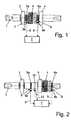
- FIG. 1shows a shaft, designed according to the invention, of an ergometer with a belt pulley arranged between two bearing points and with a measuring device, according to a first embodiment
- FIG. 2shows a shaft, designed according to the invention, of an ergometer with a belt pulley arranged outside a region between two bearing points, according to a second embodiment.
- the shaft 1illustrated schematically in FIG. 1 , of the bottom bracket of an ergometer known per se, and therefore not shown in detail, allows torque transmission from two pedal cranks, equipped with pedals, via this shaft 1 to a wrap-around drive and, further on, to an ergometer flywheel.
- the shaft 1is rotary-mounted by means of rolling bearings at two bearing points 2 , 3 in an ergometer frame, not shown in any more detail.
- the wrap-around driveis designed as a belt drive and has a belt pulley 4 which is connected fixedly in terms of rotation to the shaft 1 in at least one direction of rotation.
- a sensor means 5 and 6 for the contactless detection of deformations in the form of elastic torsions of the shaft 1 which result from torque transmission,is provided axially on both sides of the belt pulley 4 .
- the sensor-detected elastic torsionsconstitute a measure of the forces or torques applied to the shaft 1 for the arithmetic determination of the output, furnished per time unit by the user, both of the left and of the right leg of the user of the ergometer.
- the measuring meansare formed in each case by at least one magnetostrictive torque sensor means 5 and 6 and comprise a magnetically coded region 5 a , 6 a on the shaft 1 and at least one sensor coil 5 b , 6 b arranged, spaced apart from this.
- magnetostrictive torque sensor means 5 , 6 of this typehas already been explained in detail initially.
- the magnetically coded regions 5 a , 6 aare preferably formed by coatings composed of magnetostrictive material which are connected fixedly to the shaft 1 . It may, however, also be advantageous, instead, to provide separate, for example, ring-shaped built-on parts composed of magnetostrictive material which are to be connected fixedly to the shaft 1 and which are slipped onto the shaft 1 and connected to the latter nonpositively and/or positively in such a way that the elastic torsions of the shaft 1 which are to be detected are transmitted to the magnetostrictive built-on parts (not illustrated in any more detail).
- the torque sensor means 5 , 6 or their sensor coils 5 b , 6 bare in each case connected electrically or contactlessly, for example by radio or ultrasound, to an electronic storage and/or evaluation unit 7 for the processing of sensor signals 8 , 9 , generated by the sensor means 5 , 6 , of the detected deformations or elastic torsions of the shaft 1 .
- the electrical voltage required for this purposeis expediently provided by a stationary electrical network and/or by one or more accumulators.
- the belt pulley 4together with the sensor means 5 , 6 arranged axially on both sides of this, is arranged within a region of the shaft 1 which is axially delimited by the two bearing points 2 , 3 of the shaft 1 , with the result that an arrangement which is extremely compact and in which the required construction space is minimized is afforded.
- the exemplary embodiment illustrated in FIG. 2differs from the above-described variant essentially in that the belt pulley 4 is arranged axially outside the region included between the two bearing points 2 , 3 of the shaft 1 , the sensor means 5 , 6 likewise being arranged axially on both sides of the belt pulley 4 , but at least one of the sensor means 5 being arranged within said region.
- FIG. 2shows that magnetic signal transmitters 10 are arranged at a distance from one another on the circumference of the shaft 1 and cooperate with a rotational speed sensor 11 known per se, which is positioned at a radial distance above the rotational speed transmitters 10 .
- the rotational speed sensorrecords the change in the magnetic field and from this generates a rotational speed signal 12 which is transferred to the storage and/or evaluation unit 7 .
- the torque applied per time unit on the respective side of the shaft 1 and therefore the user's output furnished in each casecan be determined in the storage and/or evaluation unit 7 . Knowing the user's output, in particular that furnished by his right and/or left leg, is useful not only for informing the user of the ergometer, but also for the exact setting of the mechanical resistance of the braking device of the ergometer, for example a relevant eddy current brake or band brake.
- the brake torque or the brake power of the eddy current brake which the user of the ergometer is to counteract or counteractsis estimated from the feed voltage of the eddy current brake with the aid of a mathematically nonproportional relation.
- Accuracy in this caselies in the range of ⁇ 10% around the actual value of the brake torque, which, at least in ergometers to be used diagnostically, is deemed to be insufficient.
- a calibration of the eddy current brakeis usually carried out, in order to find the non-proportional relation between the feed voltage of the eddy current brake and its brake action (brake torque, brake power), and so that the accuracy, required according to a DIN standard, of the brake torque setting or of the torque and output indication can be achieved for the user.
- the above exemplary embodimentsare tailored to an ergometer having a wrap-around drive in the form of a belt drive.
- the inventionis not restricted to these exemplary embodiments, but also embraces wrap-around drives in the form of chain drives and also conventional bicycles with a belt or chain drive, which are equipped (not illustrated in any more detail), according to the invention, with the special sensor means 5 , 6 for detecting the elastic torsion of the shaft 1 in the region of the bottom bracket when the latter is under load during the intended use, preferably with magnetostrictive torque sensor means 5 , 6 .
Landscapes
- Health & Medical Sciences (AREA)
- Cardiology (AREA)
- Vascular Medicine (AREA)
- General Health & Medical Sciences (AREA)
- Physical Education & Sports Medicine (AREA)
- Force Measurement Appropriate To Specific Purposes (AREA)
- Excavating Of Shafts Or Tunnels (AREA)
Abstract
Description
- 1 Shaft
- 2 Bearing point
- 3 Bearing point
- 4 Belt pulley
- 5 Sensor means (torque sensor means)
- 5aMagnetically coded region
- 5bSensor coil
- 6 Sensor means (torque sensor means)
- 6aMagnetically coded region
- 6bSensor coil
- 7 Storage and/or evaluation unit
- 8 Signal
- 9 Signal
- 10 Rotational speed transmitter
- 11 Rotational speed sensor
- 12 Rotational speed signal
Claims (12)
Applications Claiming Priority (4)
| Application Number | Priority Date | Filing Date | Title |
|---|---|---|---|
| DE102007040016ADE102007040016A1 (en) | 2007-08-24 | 2007-08-24 | Method and device for measuring force, torque and power on an ergometer or bicycle |
| DE102007040016 | 2007-08-24 | ||
| DE102007040016.2 | 2007-08-24 | ||
| PCT/DE2008/001237WO2009026873A1 (en) | 2007-08-24 | 2008-07-24 | Method and device for measuring force, torque and output on an ergometer or bicycle |
Publications (2)
| Publication Number | Publication Date |
|---|---|
| US20110179862A1 US20110179862A1 (en) | 2011-07-28 |
| US8316709B2true US8316709B2 (en) | 2012-11-27 |
Family
ID=40076752
Family Applications (1)
| Application Number | Title | Priority Date | Filing Date |
|---|---|---|---|
| US12/674,472Expired - Fee RelatedUS8316709B2 (en) | 2007-08-24 | 2008-07-24 | Method and device for measuring force, torque and output on an ergometer or bicycle |
Country Status (8)
| Country | Link |
|---|---|
| US (1) | US8316709B2 (en) |
| EP (1) | EP2185250B1 (en) |
| JP (1) | JP2010537173A (en) |
| CN (1) | CN101784308B (en) |
| AT (1) | ATE512700T1 (en) |
| BR (1) | BRPI0815718A2 (en) |
| DE (1) | DE102007040016A1 (en) |
| WO (1) | WO2009026873A1 (en) |
Cited By (7)
| Publication number | Priority date | Publication date | Assignee | Title |
|---|---|---|---|---|
| US9593993B1 (en)* | 2015-08-27 | 2017-03-14 | Wellgo Pedal's Corp. | Vehicle-mounted detecting device for a bicycle |
| WO2017165448A1 (en)* | 2016-03-21 | 2017-09-28 | 4Iiii Innovations Inc. | System and method for bicycle power measurement and energy supply |
| US20170312580A1 (en)* | 2016-04-29 | 2017-11-02 | Rexon Industrial Corp., Ltd. | Resistance sensing mechanism for exercise equipment |
| US20170319906A1 (en)* | 2016-05-09 | 2017-11-09 | Peloton Interactive, Inc | Torque apparatus for exercise equipment |
| US10060738B2 (en) | 2014-08-26 | 2018-08-28 | 4Iiii Innovations Inc. | Adhesively coupled power-meter for measurement of force, torque, and power and associated methods |
| US10591371B2 (en) | 2016-06-10 | 2020-03-17 | Level Engineering, Inc. | Systems and methods for measuring drivetrain power transmission |
| US11320328B2 (en)* | 2017-05-05 | 2022-05-03 | Giant Electric Vehicle Kunshan Co., Ltd | Operation parameter detecting apparatus for vehicle |
Families Citing this family (32)
| Publication number | Priority date | Publication date | Assignee | Title |
|---|---|---|---|---|
| DE102009016106A1 (en)* | 2009-02-20 | 2010-08-26 | Rolls-Royce Deutschland Ltd & Co Kg | Method for determining rotational speed of e.g. low pressure shaft of aircraft engine, involves producing rotational speed signals for rotary shaft by magnetic coding of shaft and recognizing and evaluating signals by two signal sensors |
| DE102010011679A1 (en) | 2010-03-17 | 2011-09-22 | Schaeffler Technologies Gmbh & Co. Kg | Bottom bracket for use in e.g. bicycle, has cable outlet arranged at housing portion that is variably adapted to respective installation position of indicating and/or evaluation unit concerning to angular position with respect to bracket |
| DE102010040966A1 (en)* | 2010-09-17 | 2012-03-22 | Continental Teves Ag & Co. Ohg | Torque sensor arrangement for motor car, has magnetic field generation unit that is non-contact with shaft generating magnetic field in magnetostrictive zone, so that modulation of magnetic field in magnetostrictive zone is detected |
| TW201221928A (en)* | 2010-11-19 | 2012-06-01 | Xuan-Sen Xiao | Power measuring device for pedal crank assembly |
| FR2971483B1 (en)* | 2011-02-10 | 2013-03-15 | Mavic Sas | TORQUE MEASURING HUB, POWER MEASURING SYSTEM AND CYCLE WHEEL EQUIPPED WITH SUCH HUB OR SYSTEM |
| US8746081B2 (en)* | 2011-05-10 | 2014-06-10 | Shimano Inc. | Bicycle force sensing assembly |
| DE102011077395A1 (en) | 2011-06-10 | 2012-12-13 | Schaeffler Technologies AG & Co. KG | Device for measuring force applied on pedal of e.g. bicycle-like device in competitive sports, has deflection element for deflecting light beam directed toward surface based on radial relative motion between pedal and pedal shaft |
| CN104010569B (en)* | 2011-12-21 | 2016-08-24 | 生物磁力仪器帕克股份有限公司 | Magnetic core moves tracing device and ergometer |
| DE202012100098U1 (en) | 2012-01-12 | 2012-11-15 | Clean Mobile Ag | Control device for a vehicle |
| CN104245057B (en)* | 2012-04-19 | 2016-05-25 | 艾肯运动与健康公司 | Torque sensing pulley and related methods and systems |
| CN102749162B (en)* | 2012-07-19 | 2015-02-18 | 厦门尚宇环保股份有限公司 | Motor torque load detecting device of food waste disposer |
| DE102012214332A1 (en)* | 2012-08-10 | 2014-02-13 | Nctengineering Gmbh | Crank drive for bicycles, has sensor device for detecting torsion of pedal crankshaft between one and third axial portion of pedal crankshaft, where another sensor device detects torsion of sleeve |
| WO2014153158A1 (en) | 2013-03-14 | 2014-09-25 | Icon Health & Fitness, Inc. | Strength training apparatus with flywheel and related methods |
| EP2799327B1 (en) | 2013-05-03 | 2016-05-25 | Methode Electronics Malta Ltd. | A freewheel hub comprising a magneto-elastic sensor and bicycle, pedelec, fast pedelec or e-bike comprising the freewheel hub |
| CN105848733B (en) | 2013-12-26 | 2018-02-13 | 爱康保健健身有限公司 | Magnetic resistance mechanism in hawser apparatus |
| WO2015191445A1 (en) | 2014-06-09 | 2015-12-17 | Icon Health & Fitness, Inc. | Cable system incorporated into a treadmill |
| FR3031722B1 (en) | 2015-01-21 | 2017-02-10 | Continental Automotive France | DEVICE FOR DETERMINING THE TORQUE APPLIED TO A PEDAL AXIS |
| EP3050790B1 (en)* | 2015-01-30 | 2018-05-02 | Ncte Ag | Cordless speed, torque and power sensor for bicycles |
| CN106289603A (en)* | 2015-05-26 | 2017-01-04 | 江门金羚电机有限公司 | A kind of micro machine torque measuring device |
| US10004972B2 (en)* | 2015-12-07 | 2018-06-26 | Calgym Group Holdings Pty. Ltd. | Stationary strength training equipmment with lockable bilateral user interface |
| TWI672164B (en) | 2016-12-05 | 2019-09-21 | 美商愛康運動與健康公司 | Tread belt locking mechanism |
| TWI648081B (en) | 2016-12-05 | 2019-01-21 | 美商愛康運動與健康公司 | Pull rope resistance mechanism in treadmill |
| CN106482880A (en)* | 2016-12-30 | 2017-03-08 | 重庆樽明汽车零部件有限公司 | Motorcycle effective power dynamic checkout unit |
| DE102017109646A1 (en)* | 2017-05-05 | 2018-11-08 | Schaeffler Technologies AG & Co. KG | Determining the efficiency of a wheel bearing with the aid of a wheel force measurement system |
| CN111397789B (en)* | 2019-01-02 | 2023-12-29 | 鸿富锦精密电子(郑州)有限公司 | Torsion pressure sensing device and electric screwdriver |
| US11298577B2 (en) | 2019-02-11 | 2022-04-12 | Ifit Inc. | Cable and power rack exercise machine |
| TWI734407B (en)* | 2020-03-12 | 2021-07-21 | 天心工業股份有限公司 | Power detection system and total power estimation method |
| IT202000011956A1 (en)* | 2020-05-21 | 2021-11-21 | Favero Electronics S R L | PEDAL FOR BICYCLES |
| CN112755441B (en)* | 2020-12-25 | 2024-06-04 | 南通铁人运动用品有限公司 | Wind magnetic resistance dynamometer vehicle |
| KR102816879B1 (en)* | 2022-08-31 | 2025-06-09 | (재)예수병원유지재단 | Rehabilitation method using rehabilitation equipment to strengthen the affected side of hemiplegic patients |
| KR102778106B1 (en)* | 2022-08-31 | 2025-03-11 | (재)예수병원유지재단 | Rehabilitation Equipment for Hemiplegic Lower Limb |
| CN115219090B (en)* | 2022-09-21 | 2022-12-09 | 广东工业大学 | Wheel traction force inspection equipment of walking-aid wheelchair |
Citations (6)
| Publication number | Priority date | Publication date | Assignee | Title |
|---|---|---|---|---|
| DE3103259A1 (en) | 1981-01-31 | 1982-08-26 | Microtec Electronic GmbH, 8033 Martinsried | Ergometer |
| DE3722728C1 (en) | 1987-07-09 | 1988-12-08 | Ulrich Schoberer | Work meter for a crank drive |
| US5027303A (en) | 1989-07-17 | 1991-06-25 | Witte Don C | Measuring apparatus for pedal-crank assembly |
| EP0765804A2 (en) | 1995-09-29 | 1997-04-02 | Honda Giken Kogyo Kabushiki Kaisha | Bicycle with assisting power apparatus |
| US5816599A (en)* | 1995-06-14 | 1998-10-06 | Koyo Electronics Industries Co., Ltd | Bicycle torque detection apparatus and bicycle including the same |
| DE102005052445A1 (en) | 2005-11-03 | 2007-05-16 | Poddey Alexander | Method for operating a training device |
Family Cites Families (2)
| Publication number | Priority date | Publication date | Assignee | Title |
|---|---|---|---|---|
| DE3417893A1 (en) | 1984-05-14 | 1985-07-18 | Daimler-Benz Ag, 7000 Stuttgart | Arrangement for the contactless detection or the contactless measurement of mechanical stress states of machine parts |
| DE9415162U1 (en) | 1994-09-19 | 1994-11-24 | Petzke, Wolfgang, Dipl.-Ing., 80634 München | Electronic device for determining pedaling force |
- 2007
- 2007-08-24DEDE102007040016Apatent/DE102007040016A1/ennot_activeWithdrawn
- 2008
- 2008-07-24BRBRPI0815718-9A2Apatent/BRPI0815718A2/ennot_activeApplication Discontinuation
- 2008-07-24USUS12/674,472patent/US8316709B2/ennot_activeExpired - Fee Related
- 2008-07-24CNCN200880104545XApatent/CN101784308B/ennot_activeExpired - Fee Related
- 2008-07-24JPJP2010521292Apatent/JP2010537173A/enactivePending
- 2008-07-24EPEP08801075Apatent/EP2185250B1/ennot_activeNot-in-force
- 2008-07-24ATAT08801075Tpatent/ATE512700T1/enactive
- 2008-07-24WOPCT/DE2008/001237patent/WO2009026873A1/enactiveApplication Filing
Patent Citations (6)
| Publication number | Priority date | Publication date | Assignee | Title |
|---|---|---|---|---|
| DE3103259A1 (en) | 1981-01-31 | 1982-08-26 | Microtec Electronic GmbH, 8033 Martinsried | Ergometer |
| DE3722728C1 (en) | 1987-07-09 | 1988-12-08 | Ulrich Schoberer | Work meter for a crank drive |
| US5027303A (en) | 1989-07-17 | 1991-06-25 | Witte Don C | Measuring apparatus for pedal-crank assembly |
| US5816599A (en)* | 1995-06-14 | 1998-10-06 | Koyo Electronics Industries Co., Ltd | Bicycle torque detection apparatus and bicycle including the same |
| EP0765804A2 (en) | 1995-09-29 | 1997-04-02 | Honda Giken Kogyo Kabushiki Kaisha | Bicycle with assisting power apparatus |
| DE102005052445A1 (en) | 2005-11-03 | 2007-05-16 | Poddey Alexander | Method for operating a training device |
Non-Patent Citations (1)
| Title |
|---|
| 2010/0305879 Garb, Dec. 2, 2010.* |
Cited By (10)
| Publication number | Priority date | Publication date | Assignee | Title |
|---|---|---|---|---|
| US10060738B2 (en) | 2014-08-26 | 2018-08-28 | 4Iiii Innovations Inc. | Adhesively coupled power-meter for measurement of force, torque, and power and associated methods |
| US10458788B2 (en) | 2014-08-26 | 2019-10-29 | 4Iiii Innovations Inc. | Adhesively coupled power-meter for measurement of force, torque, and power and associated methods |
| US9593993B1 (en)* | 2015-08-27 | 2017-03-14 | Wellgo Pedal's Corp. | Vehicle-mounted detecting device for a bicycle |
| WO2017165448A1 (en)* | 2016-03-21 | 2017-09-28 | 4Iiii Innovations Inc. | System and method for bicycle power measurement and energy supply |
| US11033217B2 (en) | 2016-03-21 | 2021-06-15 | 4Iiii Innovations Inc. | Crank measurement system with improved strain gauge installation |
| US20170312580A1 (en)* | 2016-04-29 | 2017-11-02 | Rexon Industrial Corp., Ltd. | Resistance sensing mechanism for exercise equipment |
| US10220260B2 (en)* | 2016-04-29 | 2019-03-05 | Rexon Industrial Corp., Ltd. | Resistance sensing mechanism for exercise equipment |
| US20170319906A1 (en)* | 2016-05-09 | 2017-11-09 | Peloton Interactive, Inc | Torque apparatus for exercise equipment |
| US10591371B2 (en) | 2016-06-10 | 2020-03-17 | Level Engineering, Inc. | Systems and methods for measuring drivetrain power transmission |
| US11320328B2 (en)* | 2017-05-05 | 2022-05-03 | Giant Electric Vehicle Kunshan Co., Ltd | Operation parameter detecting apparatus for vehicle |
Also Published As
| Publication number | Publication date |
|---|---|
| CN101784308A (en) | 2010-07-21 |
| ATE512700T1 (en) | 2011-07-15 |
| EP2185250A1 (en) | 2010-05-19 |
| CN101784308B (en) | 2011-11-30 |
| DE102007040016A1 (en) | 2009-02-26 |
| WO2009026873A1 (en) | 2009-03-05 |
| BRPI0815718A2 (en) | 2015-02-10 |
| JP2010537173A (en) | 2010-12-02 |
| US20110179862A1 (en) | 2011-07-28 |
| EP2185250B1 (en) | 2011-06-15 |
Similar Documents
| Publication | Publication Date | Title |
|---|---|---|
| US8316709B2 (en) | Method and device for measuring force, torque and output on an ergometer or bicycle | |
| US20110239815A1 (en) | Drive device comprising a drive shaft and driving cranks | |
| CN104276251B (en) | Torque sensing system for middle shaft of electric vehicle | |
| US10444097B2 (en) | Magnetoelastic torque sensor that more accurately measures magnetic field change | |
| US8797027B2 (en) | Bottom bracket with a torque sensor unit | |
| EP1324913B2 (en) | Method and device for measuring the effort made by a cyclist | |
| US8707824B2 (en) | Bottom bracket | |
| US9097598B2 (en) | Torque sensor | |
| JP4242423B2 (en) | Belt dynamic tension measuring device and method | |
| US20130047723A1 (en) | Input Performance Measurement System for a Bicycle | |
| CN102918371B (en) | Device and method for indicating if a fastening element has reached a tensile yield limit load | |
| US20070030134A1 (en) | Wireless torque sensor | |
| TW201226874A (en) | Process and device to detect an offset-error of a moment-sensor of a bicycle-pedal drive | |
| EP2880412B1 (en) | Balancing machine for balancing vehicle wheels | |
| TWI659200B (en) | Force measurement system for sports equipment | |
| JP2019513995A (en) | Torque detection device and vehicle | |
| US20220326048A1 (en) | Sensor assembly for capturing a torque and an angular position of a rotatable shaft | |
| US20250020524A1 (en) | Crank transmission and apparatus for detecting a relative rotation of two guide elements | |
| CN203186537U (en) | Torque detection device of force-assisting bicycle | |
| CN209541960U (en) | Torsion formula axis double-side torque sensor and Moped Scooter | |
| TW201400358A (en) | Bicycle pedaling force detection apparatus production method and the apparatus made with the method thereof | |
| CN217673053U (en) | Bicycle traction type torque sensing system | |
| CN112572683A (en) | Bicycle torque transmission mechanism and system and electric power-assisted bicycle | |
| US20220080244A1 (en) | Stationary exercise device | |
| TW201817637A (en) | Crank drive apparatus for power assisted bicycle |
Legal Events
| Date | Code | Title | Description |
|---|---|---|---|
| AS | Assignment | Owner name:SCHAEFFLER TECHNOLOGIES GMBH & CO. KG, GERMANY Free format text:ASSIGNMENT OF ASSIGNORS INTEREST;ASSIGNOR:GRAB, HARALD;REEL/FRAME:024209/0187 Effective date:20100309 | |
| AS | Assignment | Owner name:SCHAEFFLER TECHNOLOGIES AG & CO. KG, GERMANY Free format text:CHANGE OF NAME;ASSIGNOR:SCHAEFFLER TECHNOLOGIES GMBH & CO. KG;REEL/FRAME:028533/0036 Effective date:20120119 | |
| STCF | Information on status: patent grant | Free format text:PATENTED CASE | |
| AS | Assignment | Owner name:SCHAEFFLER TECHNOLOGIES GMBH & CO. KG, GERMANY Free format text:MERGER AND CHANGE OF NAME;ASSIGNORS:SCHAEFFLER TECHNOLOGIES AG & CO. KG;SCHAEFFLER VERWALTUNGS 5 GMBH;REEL/FRAME:037732/0228 Effective date:20131231 Owner name:SCHAEFFLER TECHNOLOGIES AG & CO. KG, GERMANY Free format text:CHANGE OF NAME;ASSIGNOR:SCHAEFFLER TECHNOLOGIES GMBH & CO. KG;REEL/FRAME:037732/0347 Effective date:20150101 | |
| FPAY | Fee payment | Year of fee payment:4 | |
| AS | Assignment | Owner name:SCHAEFFLER TECHNOLOGIES AG & CO. KG, GERMANY Free format text:CORRECTIVE ASSIGNMENT TO CORRECT THE PROPERTY NUMBERS PREVIOUSLY RECORDED ON REEL 037732 FRAME 0347. ASSIGNOR(S) HEREBY CONFIRMS THE APP. NO. 14/553248 SHOULD BE APP. NO. 14/553258;ASSIGNOR:SCHAEFFLER TECHNOLOGIES GMBH & CO. KG;REEL/FRAME:040404/0530 Effective date:20150101 | |
| FEPP | Fee payment procedure | Free format text:MAINTENANCE FEE REMINDER MAILED (ORIGINAL EVENT CODE: REM.); ENTITY STATUS OF PATENT OWNER: LARGE ENTITY | |
| LAPS | Lapse for failure to pay maintenance fees | Free format text:PATENT EXPIRED FOR FAILURE TO PAY MAINTENANCE FEES (ORIGINAL EVENT CODE: EXP.); ENTITY STATUS OF PATENT OWNER: LARGE ENTITY | |
| STCH | Information on status: patent discontinuation | Free format text:PATENT EXPIRED DUE TO NONPAYMENT OF MAINTENANCE FEES UNDER 37 CFR 1.362 | |
| FP | Lapsed due to failure to pay maintenance fee | Effective date:20201127 |