US8316695B2 - Line leak detector and method of using same - Google Patents
Line leak detector and method of using sameDownload PDFInfo
- Publication number
- US8316695B2 US8316695B2US12/437,759US43775909AUS8316695B2US 8316695 B2US8316695 B2US 8316695B2US 43775909 AUS43775909 AUS 43775909AUS 8316695 B2US8316695 B2US 8316695B2
- Authority
- US
- United States
- Prior art keywords
- valve
- valve element
- fluid
- closed position
- flow
- Prior art date
- Legal status (The legal status is an assumption and is not a legal conclusion. Google has not performed a legal analysis and makes no representation as to the accuracy of the status listed.)
- Active, expires
Links
Images


Classifications
- G—PHYSICS
- G01—MEASURING; TESTING
- G01M—TESTING STATIC OR DYNAMIC BALANCE OF MACHINES OR STRUCTURES; TESTING OF STRUCTURES OR APPARATUS, NOT OTHERWISE PROVIDED FOR
- G01M3/00—Investigating fluid-tightness of structures
- G01M3/02—Investigating fluid-tightness of structures by using fluid or vacuum
- G01M3/26—Investigating fluid-tightness of structures by using fluid or vacuum by measuring rate of loss or gain of fluid, e.g. by pressure-responsive devices, by flow detectors
- G01M3/28—Investigating fluid-tightness of structures by using fluid or vacuum by measuring rate of loss or gain of fluid, e.g. by pressure-responsive devices, by flow detectors for pipes, cables or tubes; for pipe joints or seals; for valves ; for welds
- G01M3/2892—Investigating fluid-tightness of structures by using fluid or vacuum by measuring rate of loss or gain of fluid, e.g. by pressure-responsive devices, by flow detectors for pipes, cables or tubes; for pipe joints or seals; for valves ; for welds for underground fuel dispensing systems
- Y—GENERAL TAGGING OF NEW TECHNOLOGICAL DEVELOPMENTS; GENERAL TAGGING OF CROSS-SECTIONAL TECHNOLOGIES SPANNING OVER SEVERAL SECTIONS OF THE IPC; TECHNICAL SUBJECTS COVERED BY FORMER USPC CROSS-REFERENCE ART COLLECTIONS [XRACs] AND DIGESTS
- Y10—TECHNICAL SUBJECTS COVERED BY FORMER USPC
- Y10T—TECHNICAL SUBJECTS COVERED BY FORMER US CLASSIFICATION
- Y10T137/00—Fluid handling
- Y10T137/7287—Liquid level responsive or maintaining systems
- Y10T137/7313—Control of outflow from tank
- Y10T137/7323—By float
- Y—GENERAL TAGGING OF NEW TECHNOLOGICAL DEVELOPMENTS; GENERAL TAGGING OF CROSS-SECTIONAL TECHNOLOGIES SPANNING OVER SEVERAL SECTIONS OF THE IPC; TECHNICAL SUBJECTS COVERED BY FORMER USPC CROSS-REFERENCE ART COLLECTIONS [XRACs] AND DIGESTS
- Y10—TECHNICAL SUBJECTS COVERED BY FORMER USPC
- Y10T—TECHNICAL SUBJECTS COVERED BY FORMER US CLASSIFICATION
- Y10T137/00—Fluid handling
- Y10T137/7287—Liquid level responsive or maintaining systems
- Y10T137/7358—By float controlled valve
- Y10T137/7361—Valve opened by external means, closing or closing control by float
Definitions
- This inventionrelates to leak detection and has particular application to the detection of leakage from pressurized fuel delivery lines in dispensing operations, such as gas stations.
- USTunderground storage tanks
- EPAUnited States Environmental Protection Agency
- gphvolumetric leak rates
- one such type of leak detector devicein fuel dispensing operations, includes a valve disposed in the conduit line having a spring-biased valve element movable toward and away from an associated valve seat.
- a valvedisposed in the conduit line having a spring-biased valve element movable toward and away from an associated valve seat.
- the valve elementmoves away from the valve seat against the spring force to allow fluid to flow through the valve and toward a dispensing unit, from where the fuel is dispensed to a motor vehicle or the like.
- the dispensing unitis closed or turned off, the pressure drop across the valve element equalizes and the spring force urges the valve element back toward the valve seat and into a closed position so as to prevent any fuel from passing through the valve.
- the leak detection function of these devicesis typically provided by a bypass line around the valve such that one end thereof is in fluid communication with a first side of the valve (e.g., downstream side) and the other end of the bypass line is in fluid communication with a second side of the valve (e.g., upstream side).
- a flow detectoris typically disposed in the bypass line so as to detect any flow therethrough.
- the bypass linetypically has a relatively small cross-sectional area relative to the primary flow path through the valve so as to allow relatively small leaks in the conduit line to be detected.
- Leak detection devices operating on the basic principles outlined aboveare generally known in the art.
- U.S. Pat. No. 3,940,020 to McCrory et al.U.S. Pat. No. 3,969,923 to Howell; U.S. Pat. No. 5,014,543 to Franklin et al.; U.S. Pat. Nos. 5,072,621 and 5,315,862 to Hasselmann; and U.S. Pat. No. 5,918,268 to Lukas et al.
- These referencesdiffer primarily in the flow detector used to detect flow through the bypass line.
- Franklin et al.use a rotometer to measure the fluid flow through a bypass line.
- Lukas et al.utilize a thermal flow meter that operates on generally well know principles for determining the flow through the bypass line.
- leak detectors described abovegenerally operate for their intended purpose, there are some drawbacks that make the use of such devices problematic in fuel dispensing operations.
- such leak detectorsgenerally represent a “choke point” in the overall dispensing system that restricts the delivery of fuel to the dispensing unit.
- the delivery of fuel to motor vehicles or the likemay appear relatively slow, leading to increased dispense times and increased customer dissatisfaction.
- the effects of such flow restrictionmay be exacerbated when there are multiple users on a single fluid conduit line.
- a springis used to urge the valve element toward the closed position.
- the springalso retains the valve element in the closed position until the pressure drop across the valve element reaches the threshold level and thereby moves the valve element away from the valve seat.
- the springmay ensure proper seating of the valve element in the valve seat when the valve element is moved to the closed position.
- the spring constant of the springis typically relatively high.
- the relatively high spring constantnot only results in a large pressure drop to initiate movement of the valve element (e.g., cracking pressure) away from the valve seat, but also requires an even larger pressure drop to sustain the valve element in the opened position as the spring elongates (e.g., linear spring).
- the springworks against the flow of fluid through the valve and, for a given operating pressure (determined by the submersible pump in the tank), operates to limit the flow therethrough.
- an apparatus for detecting a leak in a fluid conduit lineincludes a housing configured to be in fluid communication with the fluid conduit line and a valve including a valve seat coupled to the housing and a valve element movable relative to the valve seat between an opened position wherein fluid is permitted to flow through the valve, and a closed position wherein fluid is prevented from flowing through the valve.
- a bypass lineis provided and includes a first end in fluid communication with a first side of the valve and a second end in fluid communication with a second side of the valve.
- a fluid flow detectoris operatively coupled to the bypass line and configured to detect the flow of fluid therethrough.
- the apparatusincludes a first mechanism configured to provide a net positive buoyant force on the valve element when the valve element and first mechanism are immersed in the fluid flowing through the conduit line. The net positive buoyant force is configured to urge the valve element toward the closed position.
- the first mechanismmay include a fluid float, which may, for example, be coupled to the valve element.
- the net positive buoyant forcemay be between approximately 0.0625 pounds-force (lbf) (0.28 Newtons (N)) and approximately 0.5 lbf (2.22 N). Other values and ranges are possible, however, depending on the specific application.
- the apparatusmay include a second mechanism, which is separate from the first mechanism, and configured to maintain the valve element in the closed position until a threshold pressure drop across the valve element is reached.
- the second mechanismmay include a magnet. More particularly, the second mechanism may include a first magnetic member coupled to the valve element and a second magnetic member coupled to the housing, wherein the first and second magnetic members are in proximity to each other when the valve element is in the closed position.
- the first and second magnetic membersmay include, for example, permanent magnets, electromagnets, and paramagnetic materials attracted to such magnets.
- the first magnetic memberincludes a portion of the valve element formed of a paramagnetic material
- the second magnetic memberincludes a permanent magnet
- the threshold pressure for moving the valve element away from the closed positionmay be between approximately one-half (0.5) pound per square inch (psi) and approximately four (4) psi.
- an apparatus for detecting a leak in a fluid conduit lineincludes a housing having an inlet, an outlet, and an interior cavity, and a valve disposed at least in part in the interior cavity between the inlet and outlet.
- the valveincludes a valve seat coupled to the housing and a valve element movable relative to the valve seat between an opened position wherein fluid is permitted to flow through the valve, and a closed position wherein fluid is prevented from flowing through the valve.
- a bypass lineis provided and includes a first end in fluid communication with a first side of the valve and a second end in fluid communication with a second side of the valve.
- a fluid flow detectoris operatively coupled to the bypass line and configured to detect the flow of fluid therethrough.
- the apparatusfurther includes a first mechanism configured to urge the valve element toward the closed position, and a second mechanism separate from the first mechanism and configured to maintain the valve element in the closed position until a threshold pressure drop across the valve element is reached.
- the first mechanismmay include a fluid float configured to provide a net positive buoyant force on the valve element when the valve element and float are immersed in the fluid flowing through the fluid conduit line. Additionally, the first mechanism may be configured to provide a substantially constant force for urging the valve element toward the closed position.
- the second mechanismmay include a magnet. Additionally, the magnet may be configured to provide a variable force on the valve element. More particularly, the second mechanism may be configured so as to provide a force on the valve element when in the closed position having a magnitude, and the magnitude of the force decreasing as the valve element moves toward the opened position. In one embodiment, the magnitude of the force provided by the second mechanism is substantially zero when the valve element is in the opened position.
- the apparatusmay be configured such that the first mechanism is the primary force-providing mechanism when the valve element is in the opened position and the second mechanism is the primary force-providing mechanism when the valve element is in the closed position.
- a dispensing systemin another embodiment, includes a tank for holding a liquid, a dispensing unit for dispensing the liquid, a fluid conduit line providing fluid communication between the tank and the dispensing unit, and a line leak detector in fluid communication with the fluid conduit line and configured to detect a leak therein.
- the leak detectorincludes a housing having an inlet, an outlet, and an interior cavity, and a valve disposed at least in part in the interior cavity between the inlet and outlet.
- the valveincludes a valve seat coupled to the housing and a valve element movable relative to the valve seat between an opened position wherein liquid is permitted to flow through the valve, and a closed position wherein liquid is prevented from flowing through the valve.
- a bypass lineis provided and includes a first end in fluid communication with a first side of the valve and a second end in fluid communication with a second side of the valve.
- a fluid flow detectoris operatively coupled to the bypass line and configured to detect the flow of liquid therethrough.
- the apparatusfurther includes a first mechanism configured to urge the valve element toward the closed position, and a second mechanism separate from the first mechanism and configured to maintain the valve element in the closed position until a threshold pressure drop across the valve element is reached.
- a method of detecting a leak in a fluid conduit lineincludes providing a leak detector having a housing with an inlet, an outlet, and an interior cavity, and a valve disposed at least in part in the interior cavity between the inlet and outlet.
- the valveincludes a valve seat coupled to the housing and a valve element movable relative to the valve seat between an opened position wherein fluid is permitted to flow through the valve, and a closed position wherein fluid is prevented from flowing through the valve.
- a bypass lineis provided and includes a first end in fluid communication with a first side of the valve and a second end in fluid communication with a second side of the valve.
- a fluid flow detectoris operatively coupled to the bypass line and configured to detect the flow of fluid therethrough.
- the methodfurther includes imposing a first force on the valve element to urge the valve element toward the closed position using a first mechanism, and imposing a second force on the valve element to maintain the valve element in the closed position until a threshold pressure drop across the valve element is reached using a second mechanism that is separate from the first mechanism.
- the methodfurther includes directing fluid flow through the bypass line on the occurrence of a leak in the fluid conduit line and detecting flow therethrough using the flow detector, thereby indicating a leak in the fluid conduit line.
- the magnitude of the first forceis generally low and less than the magnitude of the second force.
- the first forcemay be a substantially constant force while the second force may vary, such as by decreasing in magnitude as the valve element is moved away from the closed position.
- FIG. 1is a diagrammatic illustration of an exemplary fuel dispensing system including a line leak detector in accordance with an embodiment of the invention
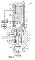
- FIG. 2is a cross-sectional view of the line leak detector shown in FIG. 1 in a closed position
- FIG. 3is a cross-sectional view of the line leak detector shown in FIG. 2 but in the opened position;
- FIG. 4is a cross-sectional view of the line leak detector shown in FIG. 2 illustrating operation of the leak detector on the occurrence of a leak.
- FIG. 1An exemplary fuel dispensing system 10 in accordance with embodiments of the invention is shown in FIG. 1 and generally includes an underground storage tank (“UST”) 12 for storing a fuel, a submersible pump 14 located in the tank 12 , and a fluid conduit line 16 that transports the fuel under pressure to one or more dispensing units 18 , shown schematically in FIG. 1 .
- the fluid conduit line 16is coupled to the submersible pump 14 via a pump manifold 20 that is typically located external to tank 12 , such as in a covered manway (not shown).
- Pump manifold 20may include a check valve 22 for preventing fuel from flowing back into tank 12 .
- the fluid conduit line 16defines a closed system containing an amount or volume of fuel that depends on several factors, including length of conduit line 16 , size of conduit line 16 (e.g., cross-sectional area), and other factors. As mentioned above, to meet EPA regulations, the integrity of the fluid conduit line 16 is regularly tested and the amount of any fuel leakage therefrom monitored.
- the fuel dispensing system 10includes a line leak detector, generally shown at 24 , for determining fuel leakage, if any, from conduit line 16 .
- leak detector 24includes a generally cylindrical body or housing 26 having a proximal end portion 28 , a distal end portion 30 and an interior cavity or bore 32 .
- the housing 26may have a unitary construction, or alternatively may be configured as a multi-part structure that among other things, facilitates assembly and maintenance of leak detector 24 .
- the distal end portion 30is adapted to be coupled to a port 34 in pump manifold 20 and may, for example, include a set of external threads that cooperate with a corresponding set of internal threads in port 34 to threadably couple leak detector 24 with pump manifold 20 .
- the external threads on housing 26are generally proximal of a distal end of the leak detector 24 such that a portion of leak detector 24 extends into the pump manifold 20 and in particular, into a flow passage thereof as discussed below.
- the inventionis not limited to the threaded connection described herein, however, as those of ordinary skill in the art will recognize other ways to couple leak detector 24 with pump manifold 20 .
- the leak detector 24is not limited to being coupled to pump manifold 20 , but may be positioned at any point along the fluid conduit line 16 generally between the check valve 22 and the dispensing unit 18 .
- the distal end portion 30 of leak detector 24includes at least one, and preferably a plurality of openings 36 (e.g., longitudinal slots) formed in the side wall 38 of housing 26 so as to provide fluid communication between the tank 12 and the interior bore 32 of leak detector 24 .
- a distal end wall 40 of leak detector 24includes an opening 42 so as to provide fluid communication between the dispensing unit 18 and the interior bore 32 of leak detector 24 (via fluid conduit line 16 ).
- pump manifold 20includes a primary flow channel 44 having a first upstream end 46 in fluid communication with the tank 12 , and a second downstream end 48 in fluid communication with dispensing unit 18 via fluid conduit line 16 .
- upstreamrefers to a location nearer to the tank 12 (and consequently submersible pump 14 ) along a flow path
- downstreamrefers to a location further from the tank 12 along the flow path.
- the mating portion 52may be positioned adjacent a distal end of the leak detector 24 .
- the inventionis not so limited as the mating portion 52 may be located at other locations of leak detector 24 , such as being spaced from the distal end thereof, for example.
- the mating portion 52 of the leak detector 24is sized to be slightly smaller than the orifice 50 and includes a seal, such as an O-ring 54 or other suitable seal, for creating a fluid tight interface between the housing 26 and the wall that defines orifice 50 of pump manifold 20 .
- submersible pump 14drives pressurized fluid from tank 12 into the upstream end 46 of pump manifold 20 and into the primary flow channel 44 .
- the pressurized fluidthen flows through the openings 36 in the side wall 38 of housing 26 and into interior bore 32 .
- the fluidis then directed through the opening 42 in the end wall 40 of housing 26 and back into the flow channel 44 of pump manifold 20 .
- Fluidthen exits pump manifold 20 through downstream end 48 and flows through fluid conduit line 16 to the dispensing unit 18 .
- leak detector 24may include additional components adapted to facilitate the detection of a leak in conduit line 16 .
- leak detector 24generally includes a valve 56 , a bypass line 58 , and a fluid flow detector 60 .
- the valve 56controls fluid flow through the leak detector 24 and includes an opened position wherein fluid is permitted to flow through the valve 56 , and a closed position wherein fluid is prevented from flowing through the valve 56 through its primary flow path.
- the bypass line 58provides an alternative fluid flow path that bypasses or circumvents the valve 56 such that fluid (albeit a relatively small amount) is capable of flowing between the tank 12 and dispensing unit 18 , even when the valve 56 is in the closed position, such as during a leak.
- the flow detector 60is configured to detect the fluid flow through the bypass line 58 .
- the valve 56may be disposed adjacent mating portion 52 , although not so limited, and includes a valve element 62 capable of moving relative to a valve seat 64 to define the opened and closed positions of valve 56 .
- the valve element 62In the opened position, the valve element 62 is spaced from the valve seat 64 so as to allow fluid to flow through the valve 56 and thus through leak detector 24 .
- the valve element 62In the closed position, the valve element 62 is engaged with the valve seat 64 to prevent any flow through the valve 56 and through leak detector 24 (at least under a normal, no leak condition).
- the valve seat 64may be disposed in the opening 42 in the end wall 40 of leak detector 24 and coupled to housing 26 thereof.
- the valve seat 64may be integrally formed with the housing 26 and generally be formed of the same material including, for example, aluminum, steel, plastics, combinations thereof, and other suitable materials.
- the valve seat 64may be configured as a separate element or insert and coupled with the housing 26 , such as by welding, bonding, fasteners, or other suitable connectors as recognized by those of ordinary skill in the art.
- the housing 26 and valve seat 64may be formed of different material.
- the housing 26may be formed of the materials identified above and the valve seat 64 may be formed of one or more of those materials (but different than the material of the housing), brass, and other suitable materials.
- the valve seat 64generally provides a smooth or otherwise prepared surface that facilitates mating with the valve element 62 to form a fluid tight interface.
- the valve element 62is movable relative to the valve seat 64 and includes a piston 66 and a stem 68 coupled to piston 66 and extending therefrom.
- the valve element 62is arranged such that the stem 68 is positioned in the interior bore 32 of housing 26 .
- the piston 66includes a generally rigid support 70 to provide a structural aspect to piston 66 , and a seal 72 that engages valve seat 64 to provide a fluid tight interface.
- Rigid support 70may be formed from aluminum, steel, plastic, such as polyoxymethylene (POM) (sold as Delrin®), or other suitable materials as recognized by those of ordinary skill in the art.
- POMpolyoxymethylene
- seal 72may be a lip seal, O-ring, cup seal, or other suitable seal for forming a fluid tight interface with valve seat 64 .
- the seal 72may substantially encase the rigid support 70 or be coupled thereto along selective portions, such as along the periphery of support 70 .
- stem 68may be integrally formed with rigid support 70 and generally be formed of the same material.
- the stem 68may be a separate component that is coupled to rigid support 70 , such as by welding, bonding, fasteners, etc., and be formed of a different material than rigid support 70 , such as aluminum, steel, plastic, or other suitable materials.
- the piston 66is disposed adjacent the valve seat 64 such that the seal 72 engages a surface thereof to form a fluid tight interface. In this way, fluid flow between the tank 12 and dispensing unit 18 through the valve 56 is prevented.
- the piston 66has been moved away from the valve seat 64 . More particularly, in one embodiment, the piston 66 moves beyond the distal end of the housing 26 so as to extend into the flow channel 44 of the pump manifold 20 . In this way, and as illustrated by arrows 74 , fluid is permitted to flow from the tank 12 to the dispensing unit 18 through the primary flow path of valve 56 .
- housing 26may include a radially extending flange 73 closely spaced about stem 68 .
- a sealmay be disposed between the stem 68 and flange 73 to support the stem 68 , but not hinder movement thereof relative to flange 73 .
- flange 73may include one or more openings 75 to provide fluid communication between bore portions 32 a and 32 b.
- the leak detector 24includes an alternative flow path through the bypass line 58 that is configured to circumvent the valve 56 .
- the bypass line 58includes a first inlet end 76 positioned upstream of valve 56 , a second outlet end 78 positioned downstream of the valve 56 , and a fluid passageway 80 extending therebetween so that the inlet and outlet ends 76 , 78 are in fluid communication.
- the inlet end 76is in fluid communication with the interior bore 32 of housing 26 , such as at a proximal end thereof (e.g., bore portion 32 b ).
- inlet end 76is upstream of the valve 56 .
- the outlet end 78is disposed in distal end wall 40 and adjacent opening 42 .
- the piston 66does not occlude or otherwise interfere with outlet end 78 . In this way, fluid is capable of flowing through bypass line 58 even though the valve element 62 is in the closed position, as will be discussed in more detail below.
- the cross-sectional area of the bypass line 58is generally less than the minimum cross-sectional area along the primary flow path through the leak detector 24 .
- the minimum cross-sectional area along the primary flow pathmay be defined by the opening in valve seat 64 .
- the opening defined by valve seat 64may have a cross-sectional area between approximately seven (7) square centimeters (cm 2 ) and approximately ten (10) cm 2 .
- leak detector 24may accommodate flow rates between approximately thirty-five (35) gallons per minute (gpm) and approximately eighty (80) gpm in a normal operating mode.
- bypass line 58may generally have a cross-sectional area of between approximately one-half (0.5) square millimeters (mm 2 ) and four (4) mm 2 .
- This rangeis also exemplary and those of ordinary skill in the art may readily determine the cross-sectional area of bypass line 58 depending on the specific application and/or other factors.
- flow ratesas little as one-half (0.5) gph or below may be detected flowing through bypass line 58 .
- the ability to detect such relatively low flow rates through bypass line 58allows leak detector 24 to detect a leak in dispensing system 10 that meets (and exceeds) current EPA standards.
- the bypass linemay include at least one (two shown) filter 82 configured to remove such debris and prevent or reduce the likelihood of blockage of bypass line 58 .
- filters 82may include sintered brass filters, for example, and are commercially available from a wide variety of vendors.
- the housing 26may have a multi-part construction that allows the filters 82 to be conveniently installed therein, as well as to allow replacement of filters 82 in a relatively quick and easy manner.
- the flow detector 60is operatively coupled to the bypass line 58 to detect fluid flowing therethrough.
- flow detector 60may include any such device capable of sensing fluid flow through bypass line 58 (e.g., fluid flow sensor) or quantifying fluid flow through bypass line 58 (e.g., fluid flow meter).
- Flow detector 60may quantify fluid flow using any acceptable metric including volume, velocity, mass flow rate, volume flow rate, etc.
- a thermal flow detectormay be utilized.
- a thermal flow detectoravailable from Sensirion, Inc. of Westlake Village, Calif.
- thermal sensor 24may be used in leak detector 24 .
- the thermal sensor described aboveis exemplary and other thermal flow sensors/meters, such as hot wire anemometers, may also be used.
- flow detectors based on other technologiesmay also be used to detect fluid flow through the bypass line 58 . These include without limitation, ultrasonic flow meters, coriolis flow meters, positive displacement meters, turbine meters, and other devices suitable for sensing or quantifying flow through a conduit.
- leak detectorsutilize a spring to perform multiple functions, including, for example: i) retaining a valve element in a closed position until a threshold pressure drop across the valve element is reached; ii) ensuring proper seating of the valve element in a valve seat as the valve element is moved toward the closed position; and iii) providing a force that urges the valve element toward the closed position.
- a single mechanisme.g., spring
- leak detector 24performs the functions outlined above, but in a manner completely different to a conventional spring.
- leak detector 24utilizes two separate mechanisms for performing one or more of the functions outlined above.
- One mechanismfor example, ultimately provides a force that urges the valve element 62 toward the closed position.
- Another mechanismprovides a force for retaining the valve element in the closed position until a threshold pressure drop across the valve element is reached. This mechanism may also ensure proper seating of the valve element in the valve seat.
- a first mechanism, generally shown at 84for providing a force that urges the valve element 62 toward the valve seat 64 operates on the principle of buoyancy. This is in sharp contrast to a spring, which relies on elastic deformation of a structural element (e.g., elongation of the spring) to provide a restoring force.
- first mechanism 84includes a float 86 operatively coupled to the valve element 62 .
- the float 86may be coupled to the stem 68 of valve element 62 , such as by a friction fit, bonding, fasteners, etc.
- the float 86may be coupled to the valve element 62 at other locations, such as at piston 66 (not shown).
- the float 86may have a hollow body configuration that collectively has a density less than that of the surrounding fluid (e.g., fuel), as known to those of ordinary skill in the art.
- the float 86may be a solid body (or hollow body) formed from suitable materials that float in the fluid.
- float 86may be formed from a suitable foam (e.g., Nitrophyl®).
- the size and/or configuration of float 86is such that the valve element assembly (i.e., collectively the valve element 62 and float 86 ) has a net positive buoyant force when the assembly is immersed in fuel during use (e.g., the buoyant force is greater than the weight of the assembly to give a net force acting in the upward direction as viewed in FIGS. 2-4 ).
- the buoyant forceis greater than the weight of the assembly to give a net force acting in the upward direction as viewed in FIGS. 2-4 .
- the net positive buoyant forceis configured to move the valve element assembly toward the closed position when there is substantially no flow through the dispensing system 10 (i.e., no leak) in conduit line 16 , and dispensing unit 18 is closed.
- the net positive buoyant forcemay be further configured to move the valve element assembly toward the closed position even when there is a small leak in the dispensing system 10 .
- the net positive buoyant forcemay be configured to move the valve element assembly toward the closed position for a leak in conduit line 16 having a leakage rate up to a value substantially equal to the maximum flow rate capable of flowing through the bypass line 58 under pump pressure.
- the net positive buoyant force on the valve element assemblyis between approximately 0.0625 lbf (0.28 N) and approximately 0.5 lbf (2.22 N). These values, however, are exemplary and different values/ranges may be used depending on the specific application.
- the leak detector 24may only include this first mechanism 84 . If, however, these aspects are of some concern or if simply desired in certain applications, the leak detector 24 may include a second mechanism, generally shown at 88 , that addresses these functions in a manner that maintains the positive aspects of the first mechanism 84 .
- the second mechanism 88may be configured to operate in a local manner as opposed to a global manner.
- the second mechanism 88may be configured to be operative when the valve element 62 is near the valve seat 64 (i.e., near the closed position), but otherwise has a small to negligible impact on the dynamics of the valve element 62 .
- This localized effect of second mechanism 88is in sharp contrast to a spring, which is operative during the entire movement of the valve element 62 between the opened and closed positions. This localized effect allows the functions of maintaining the valve element 62 in the closed position until a suitable threshold pressure drop is imposed thereacross, and facilitating proper seating of the valve element 62 in valve seat 64 to be achieved without negatively impacting the positive aspects of the first mechanism 84 .
- the second mechanism 88may be configured to operate on the principle of magnetism. Magnetism provides a localized effect when two magnetic members are in proximity to each other but has a diminished effect when the two magnetic members move away from each other. Accordingly, the second mechanism 88 may include a first magnetic member 90 associated with the valve element 62 and a second magnetic member 92 associated with the housing 26 that are configured to be attracted to one another.
- the first and second magnetic members 90 , 92may be selected from permanent magnets, electromagnets, and/or paramagnetic materials that are attracted to such magnets.
- second magnetic member 92may be a permanent magnet
- the first magnetic member 90may be a portion of valve element 62 configured as a plate member formed from a paramagnetic material.
- the first magnetic member 90may be disposed adjacent a proximal end of the stem 68 opposite the piston 66 , and the second magnetic member 92 may be coupled to the housing 26 , such that when the valve element 62 is in the closed position, the first magnetic member 90 is positioned adjacent to the second magnetic member 92 .
- the first magnetic member 90may be in contact with or in near contact with the second magnetic member 92 .
- the open positionFIG. 3
- the first magnetic member 90may be moved away from second magnetic member 92 .
- the particular choice of first and second magnetic members 90 , 92 as a paramagnetic material and permanent magnetis exemplary and those of ordinary skill in the art will recognize other configurations and combinations that are within the scope of the invention.
- line leak detector 24Operation of line leak detector 24 will now be described in reference to FIGS. 2-4 .
- the dispensing system 10is operating under a no leak condition and the dispensing unit 18 is closed, such that no fuel is being dispensed therefrom.
- the pressure upstream and downstream of leak detector 24is substantially equal to each other and substantially equal to the output pressure of the submersible pump 14 . Consequently, the valve 56 is in the closed position and there is no fluid flow through the bypass line 58 .
- This configurationis illustrated in FIG. 2 .
- the submersible pump 14is typically on or active such that the pressure upstream of the leak detector 24 remains substantially constant (and equal to pump pressure).
- the force imposed on piston 66is sufficient to overcome the net positive buoyant force from the first mechanism 84 (relatively small force) and the magnetically-induced force from the second mechanism 88 , which is the primary force that keeps the valve element 62 closed until the threshold pressure drop is reached. Consequently, the valve element 62 moves toward the opened position and fluid is capable of flowing through valve 56 along its primary flow path.
- the threshold pressure drop to overcome these forces and move the valve element 62 toward the opened positionmay be between approximately one-half (0.5) psi and approximately four (4) psi. This range is exemplary and other values are possible depending on the specific application and/or other factors.
- the net positive buoyant force from the first mechanism 84which remains relatively small, operates to urge the valve element 62 toward the closed position, and the magnetically-induced force from second mechanism 88 is very small to substantially negligible as the first and second magnetic members 90 , 92 are sufficiently separated. Accordingly, it is relatively easy to keep the valve 56 opened wide under fluid pressure and avoid flow restriction due to the return force of the valve 56 .
- FIGS. 2 and 3show and describe operation of the leak detector 24 in a normal, no-leak state, the operation of the leak detector 24 will now be described when a leak exists in conduit line 16 .
- valve 56is in the closed position.
- the downstream pressurewill begin to steadily drop. Accordingly, there will be a pressure drop across the piston 66 of valve element 62 .
- the pressure dropat least for small leaks, is configured to be below the threshold value and thus fluid pressure is not capable of overcoming the forces imposed by the first and second mechanisms 84 , 88 (e.g., primarily the second mechanism 88 ) to move the valve element 62 toward the opened position.
- the pressure drop across the piston 66may be sufficient to cause fluid to flow through the bypass line 58 .
- a leak rate from conduit line 16 greater than approximately one hundredths (0.01) gphwill typically result in a flow of fluid through the bypass line 58 .
- the flowis sensed (flow sensor) or quantified in some manner (flow meter) by flow detector 60 .
- the flow detector 60may be operatively coupled to a controller 94 and a data stream from detector 60 may be communicated thereto so as to analyze the data and make a determination of whether a leak exists in the conduit line 16 .
- Various algorithms used to analyze the data stream to determine if a leak existsare generally known in the art and do not form a part of the present invention. If it is determined that a leak exists downstream of the leak detector 24 , the submersible pump 14 may be shut off and the dispensing system 10 temporarily disabled while the leak is addressed by the appropriate personnel.
- the behavior of the leak detector 24depends on how large a leak exists. If the leak is relatively small, then once the dispensing unit 18 is closed (end of dispensing operation), the pressure drop across the piston 66 is insufficient to overcome the return force from primarily the first mechanism 84 (e.g., float 86 ), and the valve element 62 will move toward the closed position. When the first magnetic member 90 gets in proximity to the second magnetic member 92 , the valve element will snap to its closed position and stop fluid flow through valve 56 .
- the first mechanism 84e.g., float 86
- bypass line 58Due to the leak, however, fluid will flow through the bypass line 58 and be detected (e.g., sensed/metered) by flow detector 60 in the manner described above.
- the submersible pump 14may be shut off and the dispensing system 10 temporarily disabled while the leak is addressed by the appropriate personnel.
- leak detector 24may include a sensor 96 for sensing when the second magnetic member 92 is in a position that corresponds with the valve element 62 being in the closed position.
- the sensor 96may be positioned adjacent the first magnetic member 90 , such that when the valve element 62 is in the closed position, the second magnetic member 92 is in close proximity to sensor 96 (and in close proximity to first magnetic member 90 ). The sensor 96 may then, in essence, confirm that the valve element 62 is in the closed position.
- Sensor 96may be a Hall-effect sensor, a reed switch, a giant magnetorestrictive device, an optical switch, a strain gauge, or other suitable sensor for detecting the location of the valve element 62 .
- the senor 96 and the dispensing unit 18may each be operatively coupled to the controller 94 .
- the controller 94may determine if the dispensing unit 18 is opened (fuel being dispensed) or closed (fuel not being dispensed).
- the controller 94is further capable of determining whether the valve element 62 is in the closed position by utilizing sensor 96 . In this way, if a leak is sufficiently large that the valve element 62 does not move back to the closed position, then the controller 94 will detect that the dispensing unit 18 is closed and that the valve element 62 is in the opened position. Thus, the possibility of a rather large leak may then exist. Accordingly, the submersible pump 14 may be shut off and the dispensing system 10 temporarily disabled while the leak is addressed by the appropriate personnel.
- valve element 62may immediately open such that fluid does not flow through the bypass line 58 , but instead flows through the primary flow path. Similar to above, such a leak may not be detected by flow detector 60 . Again, however, controller 94 will detect that the dispensing unit 18 is closed and the valve element 62 is in the opened position such that the possibility of a rather large leak exists. As a result, the submersible pump 14 may be shut off and the dispensing system 10 temporarily disabled while the leak is addressed by the appropriate personnel.
- the leak detector 24provides a number of benefits over current leak detectors.
- a primary benefitis that, due to the particular design of leak detector 24 , flow restriction normally associated with current leak detector designs are eliminated, or at the very least, significantly reduced.
- the flow restriction of prior leak detectorsis primarily a consequence of using a single mechanism to perform several functions, including, for example, providing a force for urging the valve element toward the closed position and maintaining the valve element in the closed position until a threshold pressure drop is reached.
- the single mechanism of prior devicesis typically a spring having a high spring constant.
- the flow restriction of prior devicesis addressed herein by providing two separate mechanisms, each achieving one or more of the above-identified functions.
- the first mechanismurges the valve element toward the closed position, while the second mechanism maintains the valve element in the closed position until the threshold pressure drop is reached.
- the second mechanismmay also facilitate proper seating of the valve element in the valve seat.
- separating the functionsallows the mechanisms to be specifically tailored to those functions in an optimal manner.
- the second mechanismmay be the operative mechanism while any effects from the first mechanism are relatively small.
- the first mechanismwhen the valve is in the opened position, the first mechanism may be the operative mechanism while any effects from the second mechanisms are relatively small.
- the first mechanismmay be designed in a manner that addresses flow restriction without affecting the other functions related to the cracking pressure of the valve.
- the first mechanismmay include a float that gives the valve element assembly a relatively small net positive buoyant force that urges the valve element toward the closed position.
- the relatively small net positive buoyant force imposed by the first mechanismallows the valve element assembly to be moved rather easily under fluid pressure.
- the valvemay be opened wide for relatively low pressure drops across the valve element. This ability to open in a relatively unimpeded manner, in turn, significantly reduces any flow restriction through the valve, and higher flow rates relative to spring-based systems may be achieved for the same pressure drop across the valve element.
- the second mechanismmay operate on the principle of magnetism such that when the valve element is near the valve seat, the attractive forces properly seat the valve element in the valve seat and maintain the valve element in the closed position until the threshold pressure drop across the valve element is reached.
- the attractive forceshowever, have primarily a local effect (i.e., operating near the closed position) and diminish as the valve element moves away from the valve seat and toward the opened position.
- the second mechanismdoes not interfere with the positive benefits gained by the first mechanism as described above.
- first mechanism 84has been described herein as a float 86
- other mechanismsmay be used in accordance with alternative embodiments of the invention.
- a relatively weak (e.g., relatively small spring constant) springmay be used as the first mechanism 84 (not shown).
- the weak springis not designed to perform multiple functions, as the spring in prior art devices. Instead, the weak spring is designed to urge the valve element toward the closed position without also being the mechanism that maintains the valve element in the closed position until the threshold pressure drop is reached.
- the relatively small spring constantmay be selected such that when the valve element is in the closed position (or near the closed position such that the second mechanism is effective for closing the valve element), the spring force should be approximately equal to the weight of the valve element.
- the weak springmay have a spring constant between approximately 0.0625 lbf (0.28 N) and approximately 0.5 lbf (2.22 N). Because the weak spring is capable of readily moving under fluid pressure, similar to the float 86 , flow restriction through the valve is either eliminated or significantly reduced as compared to conventional spring-based devices. Although the force imposed by the weak spring is no longer constant, the force imposed by the spring is contemplated to remain relatively small for the entire deflection of the weak spring during use.
- valve element 62has been described herein as a piston 66 and stem 68 , other valve elements are possible that are within the scope of the present invention.
- the valve elementmay include a flap that is hingedly coupled to the valve seat (not shown).
- a stemmay be coupled to the valve seat (such as by a flexible joint) that operates in a manner similar to stem 68 described above.
Landscapes
- Physics & Mathematics (AREA)
- General Physics & Mathematics (AREA)
- Examining Or Testing Airtightness (AREA)
- Indication Of The Valve Opening Or Closing Status (AREA)
Abstract
Description
Claims (25)
Priority Applications (8)
| Application Number | Priority Date | Filing Date | Title |
|---|---|---|---|
| US12/437,759US8316695B2 (en) | 2009-05-08 | 2009-05-08 | Line leak detector and method of using same |
| EP20100250842EP2249137B1 (en) | 2009-05-08 | 2010-04-27 | Line leak detector and method of using same |
| ES10250842TES2423665T3 (en) | 2009-05-08 | 2010-04-27 | Line leak detector and use procedure |
| CN201010169986.7ACN101881376B (en) | 2009-05-08 | 2010-05-04 | Line leak detector and method of using same |
| JP2010107269AJP2010261956A (en) | 2009-05-08 | 2010-05-07 | Conduit leak detector and use thereof |
| RU2010118496ARU2426083C1 (en) | 2009-05-08 | 2010-05-07 | Procedure and device for detection of leaks in channel of pipeline if fluid medium |
| HK11100197.8AHK1146105B (en) | 2009-05-08 | 2011-01-10 | Line leak detector and method of using same |
| US13/293,864US8850872B2 (en) | 2009-05-08 | 2011-11-10 | Line leak detector and method of using same |
Applications Claiming Priority (1)
| Application Number | Priority Date | Filing Date | Title |
|---|---|---|---|
| US12/437,759US8316695B2 (en) | 2009-05-08 | 2009-05-08 | Line leak detector and method of using same |
Related Child Applications (1)
| Application Number | Title | Priority Date | Filing Date |
|---|---|---|---|
| US13/293,864Continuation-In-PartUS8850872B2 (en) | 2009-05-08 | 2011-11-10 | Line leak detector and method of using same |
Publications (2)
| Publication Number | Publication Date |
|---|---|
| US20100281953A1 US20100281953A1 (en) | 2010-11-11 |
| US8316695B2true US8316695B2 (en) | 2012-11-27 |
Family
ID=42459254
Family Applications (1)
| Application Number | Title | Priority Date | Filing Date |
|---|---|---|---|
| US12/437,759Active2030-07-22US8316695B2 (en) | 2009-05-08 | 2009-05-08 | Line leak detector and method of using same |
Country Status (6)
| Country | Link |
|---|---|
| US (1) | US8316695B2 (en) |
| EP (1) | EP2249137B1 (en) |
| JP (1) | JP2010261956A (en) |
| CN (1) | CN101881376B (en) |
| ES (1) | ES2423665T3 (en) |
| RU (1) | RU2426083C1 (en) |
Cited By (9)
| Publication number | Priority date | Publication date | Assignee | Title |
|---|---|---|---|---|
| US20140060029A1 (en)* | 2011-04-18 | 2014-03-06 | Andre-Heinrich Meinhof | Electropneumatic Position Regulator |
| US20140283582A1 (en)* | 2011-09-27 | 2014-09-25 | Delaware Capital Formation, Inc. | Method And Apparatus For Determining The Thermal Status Of Fuel In A Line Leak Detection System |
| US20150143877A1 (en)* | 2013-11-22 | 2015-05-28 | Hyundai Motor Company | Leak detection method of reducing agent pumping system |
| US9506785B2 (en) | 2013-03-15 | 2016-11-29 | Rain Bird Corporation | Remote flow rate measuring |
| US10473494B2 (en) | 2017-10-24 | 2019-11-12 | Rain Bird Corporation | Flow sensor |
| US10634538B2 (en) | 2016-07-13 | 2020-04-28 | Rain Bird Corporation | Flow sensor |
| US10809146B2 (en)* | 2016-04-27 | 2020-10-20 | Honeywell Technologies Sarl | Leakage detection device and water system comprising a leakage detection device |
| US11662242B2 (en) | 2018-12-31 | 2023-05-30 | Rain Bird Corporation | Flow sensor gauge |
| US12443208B2 (en) | 2023-02-08 | 2025-10-14 | Rain Bird Corporation | Control zone devices, systems and methods |
Families Citing this family (14)
| Publication number | Priority date | Publication date | Assignee | Title |
|---|---|---|---|---|
| US8850872B2 (en)* | 2009-05-08 | 2014-10-07 | Opw Fuel Management Systems, Inc. | Line leak detector and method of using same |
| US8776413B2 (en)* | 2011-05-09 | 2014-07-15 | Michael Willett | Systems and methods of artificial snow dispersal |
| US10585075B2 (en) | 2014-02-27 | 2020-03-10 | Elemental Scientific, Inc. | System for collecting liquid samples |
| JP6672180B2 (en) | 2014-02-27 | 2020-03-25 | エレメンタル・サイエンティフィック・インコーポレイテッドElemental Scientific, Inc. | System for collecting liquid samples from remote locations |
| CN113375981B (en) | 2015-06-26 | 2025-04-08 | 基础科学公司 | System for collecting liquid samples |
| CN105240689B (en)* | 2015-10-21 | 2018-05-04 | 长江大学 | A kind of natural gas line conveys gas leak detection device |
| WO2018071629A1 (en) | 2016-10-13 | 2018-04-19 | Young Gregory E | Line pressure isolation valve |
| CN109115865B (en)* | 2018-09-18 | 2024-07-09 | 中国石油化工股份有限公司 | Disc type coiled tubing damage detection device |
| CN109324112B (en)* | 2018-10-09 | 2020-11-10 | 河海大学 | A gate detection robot and detection method based on giant magnetoresistive element |
| CN109469829A (en)* | 2018-11-05 | 2019-03-15 | 清华大学 | An offshore system for leak monitoring of oil and gas pipelines |
| CN111006278B (en)* | 2020-01-03 | 2021-08-20 | 宁波方太厨具有限公司 | Oil fume purification device and oil fume leakage monitoring method thereof |
| FR3109214B1 (en)* | 2020-04-09 | 2022-09-02 | Sagemcom Energy & Telecom Sas | Method for detecting and locating a fluid leak |
| RU2747171C1 (en)* | 2020-08-21 | 2021-04-28 | Валерий Иванович Паутов | Device for monitoring occurrence of emergency leaks of oil and oil products from pipelines made in protective cases |
| CN112161201B (en)* | 2020-09-21 | 2023-01-24 | 湖南省大地泵业有限公司 | Sewage treatment equipment capable of preventing recontamination |
Citations (161)
| Publication number | Priority date | Publication date | Assignee | Title |
|---|---|---|---|---|
| US2043227A (en) | 1934-01-20 | 1936-06-09 | Okonite Callender Cable Co Inc | Leak indicating apparatus for oil filled electric power cables |
| US2771769A (en) | 1954-02-08 | 1956-11-27 | Acf Ind Inc | Clamping device for fuel pump tester |
| US2853874A (en) | 1954-10-30 | 1958-09-30 | Applic Et De Const Pour Materi | Apparatus for measuring leaks |
| US3085423A (en) | 1958-10-28 | 1963-04-16 | Air Reduction | Leak detection |
| US3439837A (en) | 1967-07-18 | 1969-04-22 | Robert T Hearn | Leak detecting system and method |
| US3454195A (en) | 1967-08-09 | 1969-07-08 | Red Jacket Mfg Co | Leak detecting apparatus |
| US3467135A (en)* | 1965-07-23 | 1969-09-16 | Ulrich Gunther Muskalla | Magnetic float valve |
| US3762442A (en) | 1972-01-14 | 1973-10-02 | Parker Hannifin Corp | Directional control valve with portative electromagnetic latch mechanism |
| US3788127A (en) | 1971-12-28 | 1974-01-29 | Dresser Ind | Leak detection apparatus |
| US3793876A (en) | 1972-08-10 | 1974-02-26 | Gould Inc | Battery terminal leak detector |
| US3803912A (en) | 1971-09-28 | 1974-04-16 | Tokico Ltd | Flow quantity measuring system |
| US3817097A (en) | 1972-06-05 | 1974-06-18 | T Heroux | Method and apparatus for testing hydraulic pumps |
| US3817087A (en) | 1972-10-06 | 1974-06-18 | J Mooney | Apparatus for detecting and indicating leaks in a fluid system |
| US3876009A (en) | 1972-01-28 | 1975-04-08 | Jr Wilber O Johnson | Fire extinguishing apparatus |
| US3896850A (en) | 1973-07-16 | 1975-07-29 | Hobart Waltrip | Check valve and leak indicator |
| US3928848A (en) | 1974-05-28 | 1975-12-23 | Jules Eugene Banville | Supervisory control system |
| US3938384A (en) | 1972-10-13 | 1976-02-17 | Tylan Corporation | Mass flow meter with reduced attitude sensitivity |
| US3940020A (en) | 1973-08-23 | 1976-02-24 | Gilbert & Baker Manufacturing Company | Leak detection system and method |
| US3969923A (en) | 1975-08-29 | 1976-07-20 | Valcor Engineering Corporation | Leak detector |
| US3978709A (en) | 1973-07-19 | 1976-09-07 | Chisso Corporation | Detection of leakage from liquid-transporting pipeline |
| US4043355A (en) | 1976-06-22 | 1977-08-23 | Air Products And Chemicals, Inc. | Combined flow measuring and valve leakage indicator |
| US4051716A (en) | 1976-08-10 | 1977-10-04 | Mooney Joseph R | Leak detector |
| US4058802A (en) | 1976-02-09 | 1977-11-15 | Frank Meyers | Contaminating spill detection arrangement |
| US4088987A (en) | 1976-06-24 | 1978-05-09 | Resler Glen Leroy | Fluid leak alarm system |
| US4088985A (en) | 1975-10-03 | 1978-05-09 | Sumitomo Chemical Company, Limited | Centralized monitoring system for gas leakage |
| US4090193A (en) | 1976-11-24 | 1978-05-16 | The United States Of America As Represented By The Secretary Of The Navy | Frequency multiplexed water leak detection system |
| US4096747A (en) | 1975-10-14 | 1978-06-27 | Gilson Paul R | Digital output, positive displacement flow meter |
| DE2706541A1 (en) | 1977-02-14 | 1978-08-17 | Mannesmann Ag | MONITORING DEVICE FOR THE SUPPLY LINE OF AN OIL-SUPPLIED UNIT |
| US4131216A (en) | 1977-04-28 | 1978-12-26 | Dresser Industries, Inc. | Leak detection system and method for fluid delivery piping |
| US4230187A (en) | 1979-06-19 | 1980-10-28 | Trw Inc. | Methods and apparatus for sensing wellhead pressure |
| US4300388A (en) | 1979-10-12 | 1981-11-17 | Sun Oil Company Of Pennsylvania | Method for leakage measurement |
| US4410883A (en) | 1981-04-09 | 1983-10-18 | Swiston Sr Norman J | Multiple annunciation system |
| US4461173A (en) | 1982-05-17 | 1984-07-24 | Sierra Instruments, Inc. | Multirange flowmeter |
| US4518955A (en) | 1981-05-06 | 1985-05-21 | Knut Meyer | Method and apparatus for detecting leakage in a fluid conduit system |
| US4517838A (en) | 1982-11-12 | 1985-05-21 | Ohkura Electric Co., Ltd. | Thermal mass flow meter |
| US4562731A (en) | 1979-07-24 | 1986-01-07 | Hitachi, Ltd. | Air flow meter |
| US4571996A (en) | 1984-08-10 | 1986-02-25 | Allied Corporation | Air flow sensor |
| US4573361A (en) | 1983-10-05 | 1986-03-04 | Klaus Kobold | Float-type flowmeter |
| US4586033A (en) | 1984-02-13 | 1986-04-29 | Emhart Industries, Inc. | Fluid detection system |
| US4590793A (en) | 1984-06-18 | 1986-05-27 | Staats Jr William L | Pressure pump with volumetric leak rate detector |
| DE3539167A1 (en) | 1984-11-09 | 1986-05-28 | Volkswagen AG, 3180 Wolfsburg | Device for automatically filling the cells of electric batteries with water |
| US4599890A (en) | 1984-09-05 | 1986-07-15 | Process Engineering Incorporated | Hydrostatic test apparatus |
| US4616505A (en) | 1983-05-18 | 1986-10-14 | Bronkhorst High-Tech B.V. | Fluid flow measuring device |
| US4644354A (en) | 1985-06-24 | 1987-02-17 | Emhart Industries, Inc. | Fluid detector |
| US4646069A (en) | 1985-06-24 | 1987-02-24 | Emhart Industries, Inc. | Fluid detection system |
| US4648270A (en) | 1984-02-22 | 1987-03-10 | Sirris Flow Technology, Inc. | Mass flowmeter |
| US4672842A (en) | 1985-06-26 | 1987-06-16 | Hasselmann Detlev E M | System and method for automatically monitoring liquid volume changes in storage tanks |
| US4679587A (en) | 1986-10-14 | 1987-07-14 | The Marley-Wylain Company | Leak detector with two stage piston chamber |
| US4712648A (en) | 1986-08-18 | 1987-12-15 | Ssi Technologies, Inc. | Dual magnetic coil driver and monitor sensor circuit |
| US4721950A (en) | 1986-12-22 | 1988-01-26 | Emhart Industries, Inc. | Fluid detector |
| US4727748A (en) | 1984-12-25 | 1988-03-01 | Nippon Kokan Kabushiki Kaisha | Method and apparatus for detecting leaks in a gas pipe line |
| US4736193A (en) | 1986-12-22 | 1988-04-05 | Emhart Industries, Inc. | Programmable fluid detector |
| US4740777A (en) | 1986-12-22 | 1988-04-26 | Emhart Industries, Inc. | Programmable fluid detector |
| US4791414A (en) | 1985-10-15 | 1988-12-13 | Pittway Corporation | Water-flow detector |
| US4797666A (en) | 1986-09-16 | 1989-01-10 | Baxter Carlton J | Method and apparatus for monitoring fluid flow |
| US4805701A (en) | 1987-04-07 | 1989-02-21 | Mountford George S | Fire extinguisher and alarm apparatus |
| DE3727831A1 (en)* | 1987-08-20 | 1989-03-02 | Siemens Ag | Automatic valve, particularly an inlet or outlet valve for metering pumps |
| US4811754A (en)* | 1987-03-06 | 1989-03-14 | Oy Wartsila Ab | Rinse water valve for vacuum toilet system |
| US4817415A (en) | 1987-12-14 | 1989-04-04 | Pan Am Environmental Systems, Inc. | Fluid line leak detector |
| US4827762A (en) | 1985-06-26 | 1989-05-09 | Hasselmann Detlev E M | System and method for automatically monitoring liquid volume changes in storage tanks |
| US4847599A (en) | 1987-01-16 | 1989-07-11 | Thorn Emi Flow Measurement Limited | Fluid leak detector |
| US4852054A (en) | 1986-11-20 | 1989-07-25 | Nde Technology, Inc. | Volumetric leak detection system for underground storage tanks and the like |
| US4876530A (en) | 1987-10-13 | 1989-10-24 | The Marley Company | Method and apparatus for detecting leakage in fuel storage and delivery systems |
| US4905962A (en) | 1988-09-15 | 1990-03-06 | Kaiser Aerospace & Electronics Corp. | Fast-acting electromagnetic solenoid valve |
| US4916948A (en) | 1987-12-26 | 1990-04-17 | Mitsubishi Denki Kabushiki Kaisha | Thermal flow sensor |
| US4937558A (en) | 1986-04-08 | 1990-06-26 | Societe Nationale Elf Aquitaine (Production) | Flow failure detector |
| US4942763A (en) | 1988-03-23 | 1990-07-24 | Harpster Joseph W | Flow sensor assembly |
| US4942758A (en) | 1986-12-04 | 1990-07-24 | Cofield Dennis H | High speed leak tester |
| US4966190A (en) | 1990-03-20 | 1990-10-30 | Vaporless Manufacturing, Inc. | Check valve for a leak detector |
| US4982602A (en) | 1989-02-24 | 1991-01-08 | Robert Bosch Gmbh | Air metering device |
| US4986206A (en)* | 1986-12-19 | 1991-01-22 | The Secretary Of State For Defense | Bilge drain valve |
| US5014543A (en) | 1988-07-14 | 1991-05-14 | Fe Petro Inc | Leak detector |
| US5027849A (en) | 1989-08-29 | 1991-07-02 | Gerhard Diesener | Gasoline station installation |
| US5042290A (en) | 1990-02-14 | 1991-08-27 | Vaporless Manufacturing, Inc. | Isolator for leak detector tester |
| US5050634A (en) | 1990-12-28 | 1991-09-24 | Hasstech, Inc. | Very low differential pressure switch |
| US5062442A (en) | 1989-01-18 | 1991-11-05 | Danfoss A/S | Apparatus for monitoring a fluid conduit system for leakage points |
| US5072621A (en) | 1990-06-25 | 1991-12-17 | Hasselmann Detlev E M | Pipeline leak detector apparatus and method |
| US5078006A (en) | 1990-08-30 | 1992-01-07 | Vista Research, Inc. | Methods for detection of leaks in pressurized pipeline systems |
| US5085076A (en) | 1990-11-29 | 1992-02-04 | Ames Company, Inc. | Integrated water strainer, meter, and crossover check valve |
| US5091716A (en) | 1990-07-10 | 1992-02-25 | Emco Electronics | Liquid line leak detection method and apparatus |
| US5090234A (en) | 1990-08-30 | 1992-02-25 | Vista Research, Inc. | Positive displacement pump apparatus and methods for detection of leaks in pressurized pipeline systems |
| US5103410A (en) | 1990-03-09 | 1992-04-07 | Emerson Electric Co. | Line leak test apparatus with jam proof reset |
| US5102012A (en) | 1990-08-31 | 1992-04-07 | Dayco Products, Inc. | Fuel dispensing system having a flexible hose with a static dissipater and a fuel leak detector |
| US5131262A (en) | 1991-05-02 | 1992-07-21 | Wood Lawrence C | Apparatus for detecting leaks in fuel dispensing systems |
| US5139044A (en) | 1991-08-15 | 1992-08-18 | Otten Bernard J | Fluid control system |
| US5157958A (en) | 1990-02-14 | 1992-10-27 | Vaporless Manufacturing, Inc. | Method for testing a leak detector |
| US5158207A (en) | 1991-05-15 | 1992-10-27 | Tokheim Corporation | Leak detection device |
| US5159829A (en) | 1990-12-19 | 1992-11-03 | Modern Controls, Inc. | Device for measuring gas permeation |
| US5163314A (en) | 1990-08-30 | 1992-11-17 | Vista Research, Inc. | Temperature compensated methods for detection of leaks in pressurized pipeline systems using gas controlled apparatus |
| US5170657A (en) | 1990-08-30 | 1992-12-15 | Vista Research, Inc. | Temperature compensated methods for detection of leaks in pressurized pipeline systems |
| US5189904A (en) | 1990-08-30 | 1993-03-02 | Vista Research, Inc. | Temperature compensated methods for detection of leaks in pressurized pipeline systems using piston displacement apparatus |
| US5190069A (en) | 1992-04-27 | 1993-03-02 | Richards Raymond C | Apparatus and method for detecting leaks |
| US5201212A (en) | 1991-02-13 | 1993-04-13 | Tanknology Corporation International | Line leak detector and method |
| US5228329A (en) | 1991-12-27 | 1993-07-20 | Conservation Devices, Inc. | Leak detector for fluid distribution systems serving intermittent loads |
| US5228469A (en) | 1991-08-15 | 1993-07-20 | Otten Bernard J | Fluid control system |
| US5236002A (en) | 1992-10-19 | 1993-08-17 | Grinnell Corporation | Domestic water supply shutoff valve |
| US5272646A (en) | 1991-04-11 | 1993-12-21 | Farmer Edward J | Method for locating leaks in a fluid pipeline and apparatus therefore |
| US5279155A (en) | 1993-02-04 | 1994-01-18 | Honeywell, Inc. | Mass airflow sensor |
| US5279154A (en) | 1990-06-14 | 1994-01-18 | Unit Instruments, Inc. | Thermal mass flow sensor |
| US5304757A (en) | 1992-03-26 | 1994-04-19 | Tech Team, Inc. | Combination differential and static pressure switch |
| US5309762A (en) | 1989-11-27 | 1994-05-10 | Stec Inc. | Mass flowmeter with hermetically sealed housing |
| US5317899A (en) | 1992-12-11 | 1994-06-07 | Control Engineers, Inc. | Method for detecting leaks in underground product lines |
| RU2015440C1 (en) | 1989-04-28 | 1994-06-30 | С.Макд Мерфи энд Партнерс Лтд. | Safety valve |
| US5325706A (en) | 1992-07-21 | 1994-07-05 | Gilbarco, Inc. | Dispenser leak detection |
| US5330073A (en) | 1993-04-15 | 1994-07-19 | Boston Advanced Technologies, Inc. | Gasoline dispenser leak detectors and automatic shut-off systems |
| US5333115A (en) | 1990-03-09 | 1994-07-26 | Emerson Electric Co. | Line leak test apparatus responsive to pump use |
| US5343737A (en) | 1992-09-22 | 1994-09-06 | Joseph Baumoel | Method and apparatus for leak detection and pipeline temperature modelling method and apparatus |
| US5372032A (en) | 1993-04-23 | 1994-12-13 | Filippi; Ernest A. | Pressurized piping line leak detector |
| US5375454A (en) | 1993-03-12 | 1994-12-27 | Emerson Electric Co. | Programmable pump controller |
| US5375455A (en) | 1990-08-30 | 1994-12-27 | Vista Research, Inc. | Methods for measuring flow rates to detect leaks |
| US5377529A (en) | 1993-11-15 | 1995-01-03 | Boyd; Mark A. | Leak detecting device, and method of constructing and utilizing same |
| US5383357A (en) | 1993-12-20 | 1995-01-24 | Doll; John A. | Mass air flow sensor device |
| US5390744A (en) | 1988-09-21 | 1995-02-21 | Back-Flo Alarm Valve Co., Inc. | Combined alarm and back-flow prevention arrangement for fire suppression sprinkler system |
| US5408420A (en) | 1990-03-09 | 1995-04-18 | Emerson Electric Co. | Line leak test apparatus measuring rate of pressure change in a liquid storage and dispensing system |
| US5410912A (en) | 1991-06-13 | 1995-05-02 | Mks Japan, Inc. | Mass flow sensor |
| US5419203A (en) | 1992-10-15 | 1995-05-30 | Spirax-Sarco Limited | Flow meter having a contoured plug and resilient means |
| US5421193A (en) | 1993-12-30 | 1995-06-06 | Proeco, Inc. | Method and apparatus for leak detection with float excitation and self-calibration |
| US5423457A (en) | 1993-04-30 | 1995-06-13 | Suntronic Technology Group, Inc. | Real time tank product loss detection system |
| US5461910A (en) | 1994-06-16 | 1995-10-31 | Alnor Instrument Company | Fluid flow direction and velocity monitor |
| US5483838A (en) | 1993-12-29 | 1996-01-16 | Holden; Edward S. | Fluid flow connector and gauge assembly |
| US5493100A (en) | 1994-12-28 | 1996-02-20 | Pacesetter, Inc. | Thermistor flow sensor and related method |
| US5511573A (en) | 1994-10-24 | 1996-04-30 | K N Energy, Inc. | Contaminated valve containment device |
| US5526679A (en) | 1995-01-05 | 1996-06-18 | Campo/Miller | Automatically calibrated pressurized piping leak detector |
| US5537870A (en) | 1994-10-03 | 1996-07-23 | Ford Motor Company | Contaminant free backflow reducing insert for mass air flow sensors |
| US5546801A (en) | 1994-06-01 | 1996-08-20 | Schlumberger Industries, Inc. | Water flow meter adapter for residential fire service sprinkler systems |
| US5557965A (en) | 1994-10-20 | 1996-09-24 | Dover Corporation | Pipeline leak detector |
| US5568825A (en) | 1995-12-11 | 1996-10-29 | Faulk; John W. | Automatic leak detection and shut-off system |
| US5637789A (en) | 1995-09-29 | 1997-06-10 | Lawson; William J. | Fluid leak detector |
| US5671774A (en) | 1996-06-18 | 1997-09-30 | Nelson Irrigation Corporation | Rate-of-flow control valve |
| US5834631A (en) | 1996-12-18 | 1998-11-10 | Denso Corporation | Leakage measurement method and apparatus using the same |
| US5918268A (en)* | 1995-07-07 | 1999-06-29 | Intelligent Controls, Inc. | Line leak detection |
| US5944051A (en) | 1997-09-25 | 1999-08-31 | Johnson; Augustus W. | Sprinkler drain and test valve |
| US5970797A (en) | 1998-11-04 | 1999-10-26 | Hunter; Lemna J. | Differential pressure detection system for signaling electrically-activated valve |
| US5979233A (en) | 1995-03-10 | 1999-11-09 | National Enviromental Service Company | Liquid measuring system and methods |
| US6058775A (en) | 1994-03-14 | 2000-05-09 | Patriot Sensors And Controls | Integrated liquid level and auxiliary sensor system and method |
| US6081196A (en) | 1998-06-17 | 2000-06-27 | Young; Richard Jack | Apparatus and method for multipurpose residential water flow fire alarm |
| US6082182A (en) | 1997-10-20 | 2000-07-04 | Vista Research, Inc. | Apparatus for measuring the flow rate due to a leak in a pressurized pipe system |
| US6148854A (en) | 1999-08-05 | 2000-11-21 | The United States Of America As Represented By The Secretary Of The Navy | System for leak detection from underground and aboveground fuel storage tanks |
| US6185986B1 (en) | 1997-01-30 | 2001-02-13 | Djt Products, Inc. | Line break detecting method for pressurized fluid pumping systems |
| US6239708B1 (en) | 1998-06-17 | 2001-05-29 | Richard Young | Apparatus for water flow measurement |
| US6269678B1 (en) | 2000-02-22 | 2001-08-07 | Vaporless Manufacturing Inc. | Leak detector |
| US6481265B1 (en) | 2000-11-07 | 2002-11-19 | Gunther Weber | Method and apparatus for detecting leaks |
| US6721669B2 (en) | 1996-09-02 | 2004-04-13 | Gilbarco Inc. | Method and device for measuring the volumetric flow of a fluid |
| US6741179B2 (en) | 1998-06-17 | 2004-05-25 | Richard Young | Apparatus for flow detection, measurement and control and system for use of same |
| US6804990B2 (en) | 1999-11-18 | 2004-10-19 | Gunther Weber | Method and apparatus for detecting leaks |
| US6834534B2 (en) | 2003-03-17 | 2004-12-28 | Veeder-Root Company | Fuel storage tank leak prevention and detection system and method |
| US6914531B1 (en) | 1998-06-17 | 2005-07-05 | Richard Young | Apparatus for flow detection, measurement and control and method for use of same |
| US6929018B2 (en)* | 2003-03-14 | 2005-08-16 | Gilbarco Inc. | Underground storage tank metering system in a service station environment |
| US6935161B2 (en) | 2002-06-18 | 2005-08-30 | Gilbarco Inc. | Service station leak detection and recovery system |
| US20050248465A1 (en) | 2004-05-04 | 2005-11-10 | Flaherty Fred F | Water leak alarm and method |
| US6970793B2 (en) | 2003-02-10 | 2005-11-29 | Flow International Corporation | Apparatus and method for detecting malfunctions in high-pressure fluid pumps |
| US6975964B2 (en) | 2003-10-11 | 2005-12-13 | Veeder-Root Company | Method and system for determining and monitoring the dispensing efficiency of a fuel dispensing point in a service station environment |
| US20060042690A1 (en)* | 2004-08-30 | 2006-03-02 | Toyoda Gosei Co., Ltd. | Fuel cut-off valve |
| US7028533B2 (en) | 2002-03-20 | 2006-04-18 | Mitsui Mining & Smelting Co., Ltd. | Flow rate measuring method and flowmeter, flow rate measuring section package used for them and flow rate measuring unit using them, and piping leakage inspection device using flowmeter |
| US20070084510A1 (en)* | 2005-07-29 | 2007-04-19 | Toyoda Gosei Co., Ltd. | Fuel cutoff valve |
| US20070163331A1 (en)* | 2006-01-19 | 2007-07-19 | Delaware Capital Formation, Inc. | Line leak detector |
| US20070204676A1 (en) | 2006-03-05 | 2007-09-06 | Samuel Kaplan | System and method for detecting a leak in a piping system |
| US7296474B2 (en) | 2004-10-29 | 2007-11-20 | Caterpillar Inc. | Fluid sensor having a low pressure drain |
| US20070284001A1 (en)* | 2006-06-13 | 2007-12-13 | Toyoda Gosei Co., Ltd. | Fuel cutoff valve |
| US20080029070A1 (en)* | 2003-11-14 | 2008-02-07 | Koichi Yoshihara | Float Valve |
| US7726524B2 (en)* | 2003-03-27 | 2010-06-01 | Sames Technologies | Magnetically-coupled valve |
Family Cites Families (6)
| Publication number | Priority date | Publication date | Assignee | Title |
|---|---|---|---|---|
| US5121262A (en)* | 1989-10-12 | 1992-06-09 | Conner Peripherals, Inc. | Disk drive system employing adaptive read/write channel controls and method of using same |
| SE469840B (en)* | 1992-01-20 | 1993-09-27 | Kompositprodukter Sk Fm Ab | Self-closing hopper |
| FI104126B1 (en)* | 1997-11-27 | 1999-11-15 | Jaakko Oskari Jakobsson | Arrangement for monitoring, measuring and / or detecting flows, in particular leaks, in piping |
| JPH11173443A (en)* | 1997-12-11 | 1999-06-29 | Kubota Corp | Check valve |
| JP2002089741A (en)* | 2000-09-18 | 2002-03-27 | Masazumi Ishida | A water tap with a water tap that stops with water pressure |
| JP2004132809A (en)* | 2002-10-10 | 2004-04-30 | Ing Corporation:Kk | Micro leak detection method |
- 2009
- 2009-05-08USUS12/437,759patent/US8316695B2/enactiveActive
- 2010
- 2010-04-27ESES10250842Tpatent/ES2423665T3/enactiveActive
- 2010-04-27EPEP20100250842patent/EP2249137B1/enactiveActive
- 2010-05-04CNCN201010169986.7Apatent/CN101881376B/ennot_activeExpired - Fee Related
- 2010-05-07JPJP2010107269Apatent/JP2010261956A/ennot_activeCeased
- 2010-05-07RURU2010118496Apatent/RU2426083C1/ennot_activeIP Right Cessation
Patent Citations (166)
| Publication number | Priority date | Publication date | Assignee | Title |
|---|---|---|---|---|
| US2043227A (en) | 1934-01-20 | 1936-06-09 | Okonite Callender Cable Co Inc | Leak indicating apparatus for oil filled electric power cables |
| US2771769A (en) | 1954-02-08 | 1956-11-27 | Acf Ind Inc | Clamping device for fuel pump tester |
| US2853874A (en) | 1954-10-30 | 1958-09-30 | Applic Et De Const Pour Materi | Apparatus for measuring leaks |
| US3085423A (en) | 1958-10-28 | 1963-04-16 | Air Reduction | Leak detection |
| US3467135A (en)* | 1965-07-23 | 1969-09-16 | Ulrich Gunther Muskalla | Magnetic float valve |
| US3439837A (en) | 1967-07-18 | 1969-04-22 | Robert T Hearn | Leak detecting system and method |
| US3454195A (en) | 1967-08-09 | 1969-07-08 | Red Jacket Mfg Co | Leak detecting apparatus |
| US3803912A (en) | 1971-09-28 | 1974-04-16 | Tokico Ltd | Flow quantity measuring system |
| US3788127A (en) | 1971-12-28 | 1974-01-29 | Dresser Ind | Leak detection apparatus |
| US3762442A (en) | 1972-01-14 | 1973-10-02 | Parker Hannifin Corp | Directional control valve with portative electromagnetic latch mechanism |
| US3876009A (en) | 1972-01-28 | 1975-04-08 | Jr Wilber O Johnson | Fire extinguishing apparatus |
| US3817097A (en) | 1972-06-05 | 1974-06-18 | T Heroux | Method and apparatus for testing hydraulic pumps |
| US3793876A (en) | 1972-08-10 | 1974-02-26 | Gould Inc | Battery terminal leak detector |
| US3817087A (en) | 1972-10-06 | 1974-06-18 | J Mooney | Apparatus for detecting and indicating leaks in a fluid system |
| US3938384A (en) | 1972-10-13 | 1976-02-17 | Tylan Corporation | Mass flow meter with reduced attitude sensitivity |
| US3896850A (en) | 1973-07-16 | 1975-07-29 | Hobart Waltrip | Check valve and leak indicator |
| US3978709A (en) | 1973-07-19 | 1976-09-07 | Chisso Corporation | Detection of leakage from liquid-transporting pipeline |
| US3940020A (en) | 1973-08-23 | 1976-02-24 | Gilbert & Baker Manufacturing Company | Leak detection system and method |
| US3928848A (en) | 1974-05-28 | 1975-12-23 | Jules Eugene Banville | Supervisory control system |
| US3969923A (en) | 1975-08-29 | 1976-07-20 | Valcor Engineering Corporation | Leak detector |
| US4088985A (en) | 1975-10-03 | 1978-05-09 | Sumitomo Chemical Company, Limited | Centralized monitoring system for gas leakage |
| US4096747A (en) | 1975-10-14 | 1978-06-27 | Gilson Paul R | Digital output, positive displacement flow meter |
| US4058802A (en) | 1976-02-09 | 1977-11-15 | Frank Meyers | Contaminating spill detection arrangement |
| US4043355A (en) | 1976-06-22 | 1977-08-23 | Air Products And Chemicals, Inc. | Combined flow measuring and valve leakage indicator |
| US4088987A (en) | 1976-06-24 | 1978-05-09 | Resler Glen Leroy | Fluid leak alarm system |
| US4051716A (en) | 1976-08-10 | 1977-10-04 | Mooney Joseph R | Leak detector |
| US4090193A (en) | 1976-11-24 | 1978-05-16 | The United States Of America As Represented By The Secretary Of The Navy | Frequency multiplexed water leak detection system |
| DE2706541A1 (en) | 1977-02-14 | 1978-08-17 | Mannesmann Ag | MONITORING DEVICE FOR THE SUPPLY LINE OF AN OIL-SUPPLIED UNIT |
| US4131216A (en) | 1977-04-28 | 1978-12-26 | Dresser Industries, Inc. | Leak detection system and method for fluid delivery piping |
| US4230187A (en) | 1979-06-19 | 1980-10-28 | Trw Inc. | Methods and apparatus for sensing wellhead pressure |
| US4562731A (en) | 1979-07-24 | 1986-01-07 | Hitachi, Ltd. | Air flow meter |
| US4300388A (en) | 1979-10-12 | 1981-11-17 | Sun Oil Company Of Pennsylvania | Method for leakage measurement |
| US4410883A (en) | 1981-04-09 | 1983-10-18 | Swiston Sr Norman J | Multiple annunciation system |
| US4518955A (en) | 1981-05-06 | 1985-05-21 | Knut Meyer | Method and apparatus for detecting leakage in a fluid conduit system |
| US4461173A (en) | 1982-05-17 | 1984-07-24 | Sierra Instruments, Inc. | Multirange flowmeter |
| US4517838A (en) | 1982-11-12 | 1985-05-21 | Ohkura Electric Co., Ltd. | Thermal mass flow meter |
| US4616505A (en) | 1983-05-18 | 1986-10-14 | Bronkhorst High-Tech B.V. | Fluid flow measuring device |
| US4573361A (en) | 1983-10-05 | 1986-03-04 | Klaus Kobold | Float-type flowmeter |
| US4586033A (en) | 1984-02-13 | 1986-04-29 | Emhart Industries, Inc. | Fluid detection system |
| US4648270A (en) | 1984-02-22 | 1987-03-10 | Sirris Flow Technology, Inc. | Mass flowmeter |
| US4590793A (en) | 1984-06-18 | 1986-05-27 | Staats Jr William L | Pressure pump with volumetric leak rate detector |
| US4571996A (en) | 1984-08-10 | 1986-02-25 | Allied Corporation | Air flow sensor |
| US4599890A (en) | 1984-09-05 | 1986-07-15 | Process Engineering Incorporated | Hydrostatic test apparatus |
| DE3539167A1 (en) | 1984-11-09 | 1986-05-28 | Volkswagen AG, 3180 Wolfsburg | Device for automatically filling the cells of electric batteries with water |
| US4727748A (en) | 1984-12-25 | 1988-03-01 | Nippon Kokan Kabushiki Kaisha | Method and apparatus for detecting leaks in a gas pipe line |
| US4644354A (en) | 1985-06-24 | 1987-02-17 | Emhart Industries, Inc. | Fluid detector |
| US4646069A (en) | 1985-06-24 | 1987-02-24 | Emhart Industries, Inc. | Fluid detection system |
| US4672842A (en) | 1985-06-26 | 1987-06-16 | Hasselmann Detlev E M | System and method for automatically monitoring liquid volume changes in storage tanks |
| US4827762A (en) | 1985-06-26 | 1989-05-09 | Hasselmann Detlev E M | System and method for automatically monitoring liquid volume changes in storage tanks |
| US4791414A (en) | 1985-10-15 | 1988-12-13 | Pittway Corporation | Water-flow detector |
| US4937558A (en) | 1986-04-08 | 1990-06-26 | Societe Nationale Elf Aquitaine (Production) | Flow failure detector |
| US4712648A (en) | 1986-08-18 | 1987-12-15 | Ssi Technologies, Inc. | Dual magnetic coil driver and monitor sensor circuit |
| US4797666A (en) | 1986-09-16 | 1989-01-10 | Baxter Carlton J | Method and apparatus for monitoring fluid flow |
| US4679587A (en) | 1986-10-14 | 1987-07-14 | The Marley-Wylain Company | Leak detector with two stage piston chamber |
| US4852054A (en) | 1986-11-20 | 1989-07-25 | Nde Technology, Inc. | Volumetric leak detection system for underground storage tanks and the like |
| US4942758A (en) | 1986-12-04 | 1990-07-24 | Cofield Dennis H | High speed leak tester |
| US4986206A (en)* | 1986-12-19 | 1991-01-22 | The Secretary Of State For Defense | Bilge drain valve |
| US4740777A (en) | 1986-12-22 | 1988-04-26 | Emhart Industries, Inc. | Programmable fluid detector |
| US4721950A (en) | 1986-12-22 | 1988-01-26 | Emhart Industries, Inc. | Fluid detector |
| US4736193A (en) | 1986-12-22 | 1988-04-05 | Emhart Industries, Inc. | Programmable fluid detector |
| US4847599A (en) | 1987-01-16 | 1989-07-11 | Thorn Emi Flow Measurement Limited | Fluid leak detector |
| US4811754A (en)* | 1987-03-06 | 1989-03-14 | Oy Wartsila Ab | Rinse water valve for vacuum toilet system |
| US4805701A (en) | 1987-04-07 | 1989-02-21 | Mountford George S | Fire extinguisher and alarm apparatus |
| DE3727831A1 (en)* | 1987-08-20 | 1989-03-02 | Siemens Ag | Automatic valve, particularly an inlet or outlet valve for metering pumps |
| US4876530A (en) | 1987-10-13 | 1989-10-24 | The Marley Company | Method and apparatus for detecting leakage in fuel storage and delivery systems |
| US4817415A (en) | 1987-12-14 | 1989-04-04 | Pan Am Environmental Systems, Inc. | Fluid line leak detector |
| US4916948A (en) | 1987-12-26 | 1990-04-17 | Mitsubishi Denki Kabushiki Kaisha | Thermal flow sensor |
| US4942763A (en) | 1988-03-23 | 1990-07-24 | Harpster Joseph W | Flow sensor assembly |
| US5014543A (en) | 1988-07-14 | 1991-05-14 | Fe Petro Inc | Leak detector |
| US4905962A (en) | 1988-09-15 | 1990-03-06 | Kaiser Aerospace & Electronics Corp. | Fast-acting electromagnetic solenoid valve |
| US5390744A (en) | 1988-09-21 | 1995-02-21 | Back-Flo Alarm Valve Co., Inc. | Combined alarm and back-flow prevention arrangement for fire suppression sprinkler system |
| US5062442A (en) | 1989-01-18 | 1991-11-05 | Danfoss A/S | Apparatus for monitoring a fluid conduit system for leakage points |
| US4982602A (en) | 1989-02-24 | 1991-01-08 | Robert Bosch Gmbh | Air metering device |
| RU2015440C1 (en) | 1989-04-28 | 1994-06-30 | С.Макд Мерфи энд Партнерс Лтд. | Safety valve |
| US5027849A (en) | 1989-08-29 | 1991-07-02 | Gerhard Diesener | Gasoline station installation |
| US5309762A (en) | 1989-11-27 | 1994-05-10 | Stec Inc. | Mass flowmeter with hermetically sealed housing |
| US5042290A (en) | 1990-02-14 | 1991-08-27 | Vaporless Manufacturing, Inc. | Isolator for leak detector tester |
| US5157958A (en) | 1990-02-14 | 1992-10-27 | Vaporless Manufacturing, Inc. | Method for testing a leak detector |
| US5408420A (en) | 1990-03-09 | 1995-04-18 | Emerson Electric Co. | Line leak test apparatus measuring rate of pressure change in a liquid storage and dispensing system |
| US5103410A (en) | 1990-03-09 | 1992-04-07 | Emerson Electric Co. | Line leak test apparatus with jam proof reset |
| US5333115A (en) | 1990-03-09 | 1994-07-26 | Emerson Electric Co. | Line leak test apparatus responsive to pump use |
| US4966190A (en) | 1990-03-20 | 1990-10-30 | Vaporless Manufacturing, Inc. | Check valve for a leak detector |
| US5279154A (en) | 1990-06-14 | 1994-01-18 | Unit Instruments, Inc. | Thermal mass flow sensor |
| US5072621A (en) | 1990-06-25 | 1991-12-17 | Hasselmann Detlev E M | Pipeline leak detector apparatus and method |
| US5315862A (en) | 1990-06-25 | 1994-05-31 | Hasselmann Detlev E M | Flow meter |
| US5091716A (en) | 1990-07-10 | 1992-02-25 | Emco Electronics | Liquid line leak detection method and apparatus |
| US5090234A (en) | 1990-08-30 | 1992-02-25 | Vista Research, Inc. | Positive displacement pump apparatus and methods for detection of leaks in pressurized pipeline systems |
| US5375455A (en) | 1990-08-30 | 1994-12-27 | Vista Research, Inc. | Methods for measuring flow rates to detect leaks |
| US5163314A (en) | 1990-08-30 | 1992-11-17 | Vista Research, Inc. | Temperature compensated methods for detection of leaks in pressurized pipeline systems using gas controlled apparatus |
| US5170657A (en) | 1990-08-30 | 1992-12-15 | Vista Research, Inc. | Temperature compensated methods for detection of leaks in pressurized pipeline systems |
| US5189904A (en) | 1990-08-30 | 1993-03-02 | Vista Research, Inc. | Temperature compensated methods for detection of leaks in pressurized pipeline systems using piston displacement apparatus |
| US5078006A (en) | 1990-08-30 | 1992-01-07 | Vista Research, Inc. | Methods for detection of leaks in pressurized pipeline systems |
| US5102012A (en) | 1990-08-31 | 1992-04-07 | Dayco Products, Inc. | Fuel dispensing system having a flexible hose with a static dissipater and a fuel leak detector |
| US5085076A (en) | 1990-11-29 | 1992-02-04 | Ames Company, Inc. | Integrated water strainer, meter, and crossover check valve |
| US5159829A (en) | 1990-12-19 | 1992-11-03 | Modern Controls, Inc. | Device for measuring gas permeation |
| US5050634A (en) | 1990-12-28 | 1991-09-24 | Hasstech, Inc. | Very low differential pressure switch |
| US5201212A (en) | 1991-02-13 | 1993-04-13 | Tanknology Corporation International | Line leak detector and method |
| US5272646A (en) | 1991-04-11 | 1993-12-21 | Farmer Edward J | Method for locating leaks in a fluid pipeline and apparatus therefore |
| US5131262A (en) | 1991-05-02 | 1992-07-21 | Wood Lawrence C | Apparatus for detecting leaks in fuel dispensing systems |
| US5158207A (en) | 1991-05-15 | 1992-10-27 | Tokheim Corporation | Leak detection device |
| US5410912A (en) | 1991-06-13 | 1995-05-02 | Mks Japan, Inc. | Mass flow sensor |
| US5228469A (en) | 1991-08-15 | 1993-07-20 | Otten Bernard J | Fluid control system |
| US5139044A (en) | 1991-08-15 | 1992-08-18 | Otten Bernard J | Fluid control system |
| US5228329A (en) | 1991-12-27 | 1993-07-20 | Conservation Devices, Inc. | Leak detector for fluid distribution systems serving intermittent loads |
| US5304757A (en) | 1992-03-26 | 1994-04-19 | Tech Team, Inc. | Combination differential and static pressure switch |
| US5190069A (en) | 1992-04-27 | 1993-03-02 | Richards Raymond C | Apparatus and method for detecting leaks |
| US5325706A (en) | 1992-07-21 | 1994-07-05 | Gilbarco, Inc. | Dispenser leak detection |
| US5343737A (en) | 1992-09-22 | 1994-09-06 | Joseph Baumoel | Method and apparatus for leak detection and pipeline temperature modelling method and apparatus |
| US5419203A (en) | 1992-10-15 | 1995-05-30 | Spirax-Sarco Limited | Flow meter having a contoured plug and resilient means |
| US5236002A (en) | 1992-10-19 | 1993-08-17 | Grinnell Corporation | Domestic water supply shutoff valve |
| US5317899A (en) | 1992-12-11 | 1994-06-07 | Control Engineers, Inc. | Method for detecting leaks in underground product lines |
| US5279155A (en) | 1993-02-04 | 1994-01-18 | Honeywell, Inc. | Mass airflow sensor |
| US5375454A (en) | 1993-03-12 | 1994-12-27 | Emerson Electric Co. | Programmable pump controller |
| US5330073A (en) | 1993-04-15 | 1994-07-19 | Boston Advanced Technologies, Inc. | Gasoline dispenser leak detectors and automatic shut-off systems |
| US5372032A (en) | 1993-04-23 | 1994-12-13 | Filippi; Ernest A. | Pressurized piping line leak detector |
| US5423457A (en) | 1993-04-30 | 1995-06-13 | Suntronic Technology Group, Inc. | Real time tank product loss detection system |
| US5377529A (en) | 1993-11-15 | 1995-01-03 | Boyd; Mark A. | Leak detecting device, and method of constructing and utilizing same |
| US5383357A (en) | 1993-12-20 | 1995-01-24 | Doll; John A. | Mass air flow sensor device |
| US5483838A (en) | 1993-12-29 | 1996-01-16 | Holden; Edward S. | Fluid flow connector and gauge assembly |
| US5421193A (en) | 1993-12-30 | 1995-06-06 | Proeco, Inc. | Method and apparatus for leak detection with float excitation and self-calibration |
| US6058775A (en) | 1994-03-14 | 2000-05-09 | Patriot Sensors And Controls | Integrated liquid level and auxiliary sensor system and method |
| US5546801A (en) | 1994-06-01 | 1996-08-20 | Schlumberger Industries, Inc. | Water flow meter adapter for residential fire service sprinkler systems |
| US5461910A (en) | 1994-06-16 | 1995-10-31 | Alnor Instrument Company | Fluid flow direction and velocity monitor |
| US5537870A (en) | 1994-10-03 | 1996-07-23 | Ford Motor Company | Contaminant free backflow reducing insert for mass air flow sensors |
| US5557965A (en) | 1994-10-20 | 1996-09-24 | Dover Corporation | Pipeline leak detector |
| US5511573A (en) | 1994-10-24 | 1996-04-30 | K N Energy, Inc. | Contaminated valve containment device |
| US5493100A (en) | 1994-12-28 | 1996-02-20 | Pacesetter, Inc. | Thermistor flow sensor and related method |
| US5526679A (en) | 1995-01-05 | 1996-06-18 | Campo/Miller | Automatically calibrated pressurized piping leak detector |
| US5979233A (en) | 1995-03-10 | 1999-11-09 | National Enviromental Service Company | Liquid measuring system and methods |
| US5918268A (en)* | 1995-07-07 | 1999-06-29 | Intelligent Controls, Inc. | Line leak detection |
| US5637789A (en) | 1995-09-29 | 1997-06-10 | Lawson; William J. | Fluid leak detector |
| US5568825A (en) | 1995-12-11 | 1996-10-29 | Faulk; John W. | Automatic leak detection and shut-off system |
| US5671774A (en) | 1996-06-18 | 1997-09-30 | Nelson Irrigation Corporation | Rate-of-flow control valve |
| US6721669B2 (en) | 1996-09-02 | 2004-04-13 | Gilbarco Inc. | Method and device for measuring the volumetric flow of a fluid |
| US5834631A (en) | 1996-12-18 | 1998-11-10 | Denso Corporation | Leakage measurement method and apparatus using the same |
| US6185986B1 (en) | 1997-01-30 | 2001-02-13 | Djt Products, Inc. | Line break detecting method for pressurized fluid pumping systems |
| US5944051A (en) | 1997-09-25 | 1999-08-31 | Johnson; Augustus W. | Sprinkler drain and test valve |
| US6082182A (en) | 1997-10-20 | 2000-07-04 | Vista Research, Inc. | Apparatus for measuring the flow rate due to a leak in a pressurized pipe system |
| US6081196A (en) | 1998-06-17 | 2000-06-27 | Young; Richard Jack | Apparatus and method for multipurpose residential water flow fire alarm |
| US6239708B1 (en) | 1998-06-17 | 2001-05-29 | Richard Young | Apparatus for water flow measurement |
| US6914531B1 (en) | 1998-06-17 | 2005-07-05 | Richard Young | Apparatus for flow detection, measurement and control and method for use of same |
| US6741179B2 (en) | 1998-06-17 | 2004-05-25 | Richard Young | Apparatus for flow detection, measurement and control and system for use of same |
| US5970797A (en) | 1998-11-04 | 1999-10-26 | Hunter; Lemna J. | Differential pressure detection system for signaling electrically-activated valve |
| US6148854A (en) | 1999-08-05 | 2000-11-21 | The United States Of America As Represented By The Secretary Of The Navy | System for leak detection from underground and aboveground fuel storage tanks |
| US6804990B2 (en) | 1999-11-18 | 2004-10-19 | Gunther Weber | Method and apparatus for detecting leaks |
| US6269678B1 (en) | 2000-02-22 | 2001-08-07 | Vaporless Manufacturing Inc. | Leak detector |
| US6427516B2 (en)* | 2000-02-22 | 2002-08-06 | Vaporless Manufacturing, Inc. | Leak detector |
| US6481265B1 (en) | 2000-11-07 | 2002-11-19 | Gunther Weber | Method and apparatus for detecting leaks |
| US7028533B2 (en) | 2002-03-20 | 2006-04-18 | Mitsui Mining & Smelting Co., Ltd. | Flow rate measuring method and flowmeter, flow rate measuring section package used for them and flow rate measuring unit using them, and piping leakage inspection device using flowmeter |
| US6935161B2 (en) | 2002-06-18 | 2005-08-30 | Gilbarco Inc. | Service station leak detection and recovery system |
| US6962269B2 (en) | 2002-06-18 | 2005-11-08 | Gilbarco Inc. | Service station leak detection and recovery system |
| US7455194B2 (en) | 2002-06-18 | 2008-11-25 | Gilbarco Inc. | Service station leak detection and recovery system |
| US6970793B2 (en) | 2003-02-10 | 2005-11-29 | Flow International Corporation | Apparatus and method for detecting malfunctions in high-pressure fluid pumps |
| US6935356B2 (en) | 2003-03-14 | 2005-08-30 | Gilbarco Inc. | Underground storage tank metering system in a service station environment |
| US6929018B2 (en)* | 2003-03-14 | 2005-08-16 | Gilbarco Inc. | Underground storage tank metering system in a service station environment |
| US6834534B2 (en) | 2003-03-17 | 2004-12-28 | Veeder-Root Company | Fuel storage tank leak prevention and detection system and method |
| US7726524B2 (en)* | 2003-03-27 | 2010-06-01 | Sames Technologies | Magnetically-coupled valve |
| US6975964B2 (en) | 2003-10-11 | 2005-12-13 | Veeder-Root Company | Method and system for determining and monitoring the dispensing efficiency of a fuel dispensing point in a service station environment |
| US20080029070A1 (en)* | 2003-11-14 | 2008-02-07 | Koichi Yoshihara | Float Valve |
| US20050248465A1 (en) | 2004-05-04 | 2005-11-10 | Flaherty Fred F | Water leak alarm and method |
| US20060042690A1 (en)* | 2004-08-30 | 2006-03-02 | Toyoda Gosei Co., Ltd. | Fuel cut-off valve |
| US7296474B2 (en) | 2004-10-29 | 2007-11-20 | Caterpillar Inc. | Fluid sensor having a low pressure drain |
| US20070084510A1 (en)* | 2005-07-29 | 2007-04-19 | Toyoda Gosei Co., Ltd. | Fuel cutoff valve |
| US20070163331A1 (en)* | 2006-01-19 | 2007-07-19 | Delaware Capital Formation, Inc. | Line leak detector |
| US20070204676A1 (en) | 2006-03-05 | 2007-09-06 | Samuel Kaplan | System and method for detecting a leak in a piping system |
| US20070284001A1 (en)* | 2006-06-13 | 2007-12-13 | Toyoda Gosei Co., Ltd. | Fuel cutoff valve |
Non-Patent Citations (3)
| Title |
|---|
| Ann-Sofie Hallback; European Search Report issued in related European Patent Application No. EP 10 25 0842; Aug. 12, 2010; 8 pages; European Patent Office. |
| English translation of Decision on Grant issued by the Patent Office of the Russian Federation in related Russian Patent Application No. 2010118496; Jan. 25, 2011; 14 pages. |
| Series ARV Thermoplastic Air Release Valves, Plast-O-Matic Valves, Inc., located on http://www.archive.org, archived on Mar. 17, 2005.* |
Cited By (12)
| Publication number | Priority date | Publication date | Assignee | Title |
|---|---|---|---|---|
| US20140060029A1 (en)* | 2011-04-18 | 2014-03-06 | Andre-Heinrich Meinhof | Electropneumatic Position Regulator |
| US9534617B2 (en)* | 2011-04-18 | 2017-01-03 | Siemens Aktiengesellschaft | Electropneumatic position regulator |
| US20140283582A1 (en)* | 2011-09-27 | 2014-09-25 | Delaware Capital Formation, Inc. | Method And Apparatus For Determining The Thermal Status Of Fuel In A Line Leak Detection System |
| US9347849B2 (en)* | 2011-09-27 | 2016-05-24 | Opw Fuel Management Systems, Inc. | Method and apparatus for determining the thermal status of fuel in a line leak detection system |
| US9506785B2 (en) | 2013-03-15 | 2016-11-29 | Rain Bird Corporation | Remote flow rate measuring |
| US20150143877A1 (en)* | 2013-11-22 | 2015-05-28 | Hyundai Motor Company | Leak detection method of reducing agent pumping system |
| US9638086B2 (en)* | 2013-11-22 | 2017-05-02 | Hyundai Motor Company | Leak detection method of reducing agent pumping system |
| US10809146B2 (en)* | 2016-04-27 | 2020-10-20 | Honeywell Technologies Sarl | Leakage detection device and water system comprising a leakage detection device |
| US10634538B2 (en) | 2016-07-13 | 2020-04-28 | Rain Bird Corporation | Flow sensor |
| US10473494B2 (en) | 2017-10-24 | 2019-11-12 | Rain Bird Corporation | Flow sensor |
| US11662242B2 (en) | 2018-12-31 | 2023-05-30 | Rain Bird Corporation | Flow sensor gauge |
| US12443208B2 (en) | 2023-02-08 | 2025-10-14 | Rain Bird Corporation | Control zone devices, systems and methods |
Also Published As
| Publication number | Publication date |
|---|---|
| EP2249137A1 (en) | 2010-11-10 |
| RU2426083C1 (en) | 2011-08-10 |
| CN101881376A (en) | 2010-11-10 |
| EP2249137B1 (en) | 2013-05-08 |
| CN101881376B (en) | 2014-09-03 |
| ES2423665T3 (en) | 2013-09-23 |
| JP2010261956A (en) | 2010-11-18 |
| US20100281953A1 (en) | 2010-11-11 |
| HK1146105A1 (en) | 2011-05-13 |
Similar Documents
| Publication | Publication Date | Title |
|---|---|---|
| US8316695B2 (en) | Line leak detector and method of using same | |
| US8850872B2 (en) | Line leak detector and method of using same | |
| US7392817B2 (en) | Water conservation safety shut-off valve | |
| US5072621A (en) | Pipeline leak detector apparatus and method | |
| AU2006257205B2 (en) | Fluid flow controller | |
| EP2982891A2 (en) | Water safety shut-off valve | |
| US20070163331A1 (en) | Line leak detector | |
| BRPI0722233A2 (en) | APPARATUS AND METHOD FOR SUPPLYING AN AIRCRAFT TANK SYSTEM | |
| JP2012505358A (en) | Device for determining the position of a valve | |
| CN110168337A (en) | Line pressure isolation valve | |
| CN102549326A (en) | Speed control drive section with failsafe valve | |
| GB2454465A (en) | A system for controlling flow of water in a building | |
| US5158207A (en) | Leak detection device | |
| JP7122205B2 (en) | fuel supply | |
| KR101687943B1 (en) | A water appliance having a flow control unit and a filter assembly | |
| HK1146105B (en) | Line leak detector and method of using same | |
| US8196617B2 (en) | Vapor recovery detection means | |
| KR101510711B1 (en) | Constant Flow Regulator Preventing Backflow of Fluid | |
| FR3043461A1 (en) | DEVICE FOR DETECTING WATER LEAKS WITH MICRO-FLOW FUNCTION | |
| EP1704398A1 (en) | Arrangement for measuring, indicating, and/or shutting off a leak or a flow in a pressurised piping system |
Legal Events
| Date | Code | Title | Description |
|---|---|---|---|
| AS | Assignment | Owner name:DELAWARE CAPITAL FORMATION, INC., DELAWARE Free format text:ASSIGNMENT OF ASSIGNORS INTEREST;ASSIGNOR:JARVIE, IAN F.;REEL/FRAME:024146/0425 Effective date:20090507 | |
| STCF | Information on status: patent grant | Free format text:PATENTED CASE | |
| AS | Assignment | Owner name:CLOVE PARK INSURANCE COMPANY, NEW YORK Free format text:ASSIGNMENT OF ASSIGNORS INTEREST;ASSIGNOR:DELAWARE CAPITAL FORMATION, INC.;REEL/FRAME:030820/0150 Effective date:20130630 Owner name:OPW FUEL MANAGEMENT SYSTEMS, INC., ILLINOIS Free format text:ASSIGNMENT OF ASSIGNORS INTEREST;ASSIGNOR:CP FORMATION LLC;REEL/FRAME:030820/0108 Effective date:20130701 Owner name:CP FORMATION LLC, NEW YORK Free format text:ASSIGNMENT OF ASSIGNORS INTEREST;ASSIGNOR:CLOVE PARK INSURANCE COMPANY;REEL/FRAME:030820/0132 Effective date:20130630 | |
| FPAY | Fee payment | Year of fee payment:4 | |
| MAFP | Maintenance fee payment | Free format text:PAYMENT OF MAINTENANCE FEE, 8TH YEAR, LARGE ENTITY (ORIGINAL EVENT CODE: M1552); ENTITY STATUS OF PATENT OWNER: LARGE ENTITY Year of fee payment:8 | |
| MAFP | Maintenance fee payment | Free format text:PAYMENT OF MAINTENANCE FEE, 12TH YEAR, LARGE ENTITY (ORIGINAL EVENT CODE: M1553); ENTITY STATUS OF PATENT OWNER: LARGE ENTITY Year of fee payment:12 |