US8316499B2 - Apparatus for holding a cleaning sheet in a cleaning implement - Google Patents
Apparatus for holding a cleaning sheet in a cleaning implementDownload PDFInfo
- Publication number
- US8316499B2 US8316499B2US12/985,257US98525711AUS8316499B2US 8316499 B2US8316499 B2US 8316499B2US 98525711 AUS98525711 AUS 98525711AUS 8316499 B2US8316499 B2US 8316499B2
- Authority
- US
- United States
- Prior art keywords
- jaw
- trap
- sheet
- forward portion
- robot
- Prior art date
- Legal status (The legal status is an assumption and is not a legal conclusion. Google has not performed a legal analysis and makes no representation as to the accuracy of the status listed.)
- Expired - Fee Related
Links
Images


Classifications
- A—HUMAN NECESSITIES
- A47—FURNITURE; DOMESTIC ARTICLES OR APPLIANCES; COFFEE MILLS; SPICE MILLS; SUCTION CLEANERS IN GENERAL
- A47L—DOMESTIC WASHING OR CLEANING; SUCTION CLEANERS IN GENERAL
- A47L11/00—Machines for cleaning floors, carpets, furniture, walls, or wall coverings
- A47L11/40—Parts or details of machines not provided for in groups A47L11/02 - A47L11/38, or not restricted to one of these groups, e.g. handles, arrangements of switches, skirts, buffers, levers
- A—HUMAN NECESSITIES
- A47—FURNITURE; DOMESTIC ARTICLES OR APPLIANCES; COFFEE MILLS; SPICE MILLS; SUCTION CLEANERS IN GENERAL
- A47L—DOMESTIC WASHING OR CLEANING; SUCTION CLEANERS IN GENERAL
- A47L13/00—Implements for cleaning floors, carpets, furniture, walls, or wall coverings
- A47L13/10—Scrubbing; Scouring; Cleaning; Polishing
- A47L13/20—Mops
- A47L13/24—Frames for mops; Mop heads
- A47L13/254—Plate frames
- A47L13/256—Plate frames for mops made of cloth
- Y—GENERAL TAGGING OF NEW TECHNOLOGICAL DEVELOPMENTS; GENERAL TAGGING OF CROSS-SECTIONAL TECHNOLOGIES SPANNING OVER SEVERAL SECTIONS OF THE IPC; TECHNICAL SUBJECTS COVERED BY FORMER USPC CROSS-REFERENCE ART COLLECTIONS [XRACs] AND DIGESTS
- Y10—TECHNICAL SUBJECTS COVERED BY FORMER USPC
- Y10T—TECHNICAL SUBJECTS COVERED BY FORMER US CLASSIFICATION
- Y10T29/00—Metal working
- Y10T29/49—Method of mechanical manufacture
- Y10T29/49826—Assembling or joining
- Y10T29/49863—Assembling or joining with prestressing of part
- Y10T29/4987—Elastic joining of parts
Definitions
- Certain cleaning solutionsinvolve the use of cleaning or mopping cloths or sheets.
- Sweeper devicesexist that are configured to hold such cleaning sheets so that one or more held portions of a sheet are in a fixed position relative to the holder and an unheld portion of the sheet is in relative tension against a surface of the device.
- many conventional cleaning sheet holding mechanismsmay result in injury or discomfort to the user when mounting the sheet in the holder.
- Certain embodiments disclosed hereinare composed of one or more traps comprising a first jaw comprising a base portion and a forward portion having a forward surface and a semi-rigid second jaw comprising a base portion spaced from the base portion of the first jaw and a forward portion having a forward surface, the forward portion of the second jaw flexible in at least a first direction substantially orthogonal to the forward portion of the second jaw.
- the second jawWhen the second jaw is relaxed (e.g., in a natural condition, with no external forces applied to it to cause it to flex), the forward portion of the second jaw is substantially coplanar with the forward portion of the first jaw and the forward surface of the forward portion of the second jaw faces the forward surface of the forward portion of the first jaw.
- the forward surface of the forward portion of the second jawis spaced further from the forward surface of the forward portion of the first jaw than it is when the second jaw is relaxed.
- Some embodimentscomprise a robot comprising a body and a platform associated with the body (e.g., an integral part of the body or removably attached to it), the platform having a first surface facing away from the body and substantially parallel to and facing towards a surface in an environment in which the robot is configured to move.
- the embodimentmay have a plurality of substantially longitudinal traps attached to a second surface of the platform (opposite to the first surface of the platform) so that at least two of the traps are positioned on substantially parallel longitudinal lines.
- the first trapis configured to receive a first portion of a sheet and the second trap is configured to receive a second portion of the sheet, the first portion of the sheet spaced from the second portion of the sheet such that when the first sheet portion is received by the first trap and the second sheet portion is received by the second trap, a third sheet portion between the first and second sheet portions may be held against the first surface of the platform.
- the first trapmay be configured as described above.
- itmay comprise a first jaw comprising a base portion and a forward portion having a forward surface and a semi-rigid second jaw comprising a base portion spaced from the base portion of the first jaw and a forward portion having a forward surface, the forward portion flexible in at least a first direction substantially orthogonal to the forward portion (i.e., when the robot is placed on a surface so as to travel over it, the first direction is substantially in the direction towards that surface).
- the forward portion of the second jawis substantially coplanar with the forward portion of the first jaw and the forward surface of the forward portion of the second jaw faces the forward surface of the forward portion of the first jaw.
- the forward surface of the forward portion of the second jawis spaced further from the forward surface of the forward portion of the first jaw than it is when the second jaw is relaxed.
- the robotmay be configured to move in the environment in accordance with logic contained in an on-board processor.
- FIG. 1illustrates an isometric view of an example embodiment comprising two holders arranged so as to hold a sheet against a pad and FIG. 1B illustrates an example embodiment of a robot.
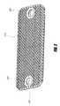
- FIG. 2illustrates an isometric view of the side of the pad against which the sheet is held in the embodiment of FIG. 1 .
- FIG. 3illustrates an isometric view of a cross-section of an example embodiment such as that of FIG. 1 .
- FIG. 4illustrates an orthographic view of the cross-section of the embodiment illustrated in FIG. 3 .
- FIG. 5illustrates an isometric view of flexed portions (as for sheet insertion or removal) of an embodiment such as that of FIG. 1 .
- FIG. 6illustrates an orthographic view of flexed portions (as for sheet insertion or removal) of an embodiment such as that of FIG. 1 .
- FIG. 7illustrates a detailed orthographic view of region A of the embodiment illustrated in FIG. 6 .
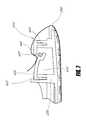
- FIG. 8illustrates a detailed orthographic view of region B of the embodiment illustrated in FIG. 6 .
- Certain embodimentsmay use one or more holders, and certain embodiments may use two or more holders to keep a sheet relatively taut against a surface of an object to which the sheet is otherwise unattached. Some embodiments are such that they are amenable to use by a user with minimal risk of injury to that user's fingers as compared to certain known sheet holding systems.
- FIGS. 1-8 and described hereinIllustrated in FIGS. 1-8 and described herein is an example holding apparatus for holding a dusting, mopping, or cleaning sheet configured for use in dusting, mopping, or cleaning a floor (sometimes collectively referred to herein as “cleaning”).
- the sheetmay be impregnated with mineral oil and/or wax to help trap dirt and dust when swept across a work surface, such as a floor.
- the sheetmay be impregnated with cleaning solutions and/or wood preservatives, such as cleaning solutions including some or all of the following ingredients and/or other ingredients: purified water, butoxypropanol, alkyl polyglycoside, dialkyl dimethyl ammonium chloride, polyoxyethylene castor oil, linear alkylbenzene sulfonate, sodium salt, acrylic copolymer, benzisothiazolinone, cleaning agents, fragrances, etc.
- cleaning solutionsincluding some or all of the following ingredients and/or other ingredients: purified water, butoxypropanol, alkyl polyglycoside, dialkyl dimethyl ammonium chloride, polyoxyethylene castor oil, linear alkylbenzene sulfonate, sodium salt, acrylic copolymer, benzisothiazolinone, cleaning agents, fragrances, etc.
- the example holding apparatuscomprises a support structure and traps that may be substantially linear and which optionally extend longitudinally for most of the length of the support structure.
- the illustrated apparatusprovides a gripping surface for a sheet, such as a cleaning sheet, for substantially the length of the support structure, if the sheet is at least that long; a substantially uniform tension on the sheet across the support structure; and an intuitive and “pinch-free” sheet insertion operation that reduces or substantially eliminates the risk of a user's fingers being pinched when inserting the sheet into the holder.
- the more secure holding of the sheet relative to that provided by conventional holdersenables the use of such cleaning sheets in applications where there is no human supervision, such as in the case of a robotic cleaning implement which needs to operate without user supervision.
- the sheetpreferably stays in place in the holder to prevent or reduce the possibility of entanglement of the sheet with the robot wheels (or other means of movement, such as treads, or other components of the robot) or with furniture or other obstacles in the environment in which the robot moves.
- FIG. 1illustrates an embodiment of a support structure for a cleaning sheet.
- a robot apparatus and systemare described for performing multiple cleaning functions on the floor, including a dusting and a mopping function.
- a support structuresuch as that illustrated in FIG. 1 may be configured to attach to a robotic floor cleaning apparatus disclosed therein.
- An example embodiment of a robot 100 Bis illustrated in FIG. 1B herein.
- Another embodimentis configured to attach to a pole, rod, or similar handle apparatus.
- Yet another embodimentis configured to attach to a hand grip.
- the support structure illustrated in FIG. 1includes a pad 200 (which may be a plate or other structure and may have a first surface 210 and a bottom surface 310 ), a support chassis 220 , and one or more sheet traps 260 extending longitudinally on either side of the support structure.
- the pad 200may be integral with the support chassis 220 or may be removably associated with it.
- Some or all of the illustrated traps 260includes two grip jaws: an inner jaw 230 and an outer jaw 240 .
- the grip jaws 230 , 240meet or come close to meeting at a slit 270 over a cavity 410 ( FIG. 3 ).
- the two jaws of a trap 260may remain 1.0 mm, 0.5 mm, 0.1 mm or less apart, although other dimensions may be used.
- the slit 270may also be 1.5 mm, 5.0 mm, or 1.0 cm wide or wider, although other dimensions may be used.
- the slit 270may be configured so that it is at least narrow enough such that when the trap 260 is used to hold a sheet, the sheet can not easily slip out of the trap 260 .
- the sheetwill slip out of the trap 260 if a pulling pressure above a certain predefined level is applied to the sheet, perhaps at a particular angle.
- the width of the support structure(i.e., its extent from left of the first trap 260 to right of second trap 260 in FIG. 1 ) is approximately 101 mm, and in some embodiments it may range from approximately 90 mm to approximately 120 mm, while in other embodiments it may be larger or smaller.
- the length of the support structuremay be approximately 248 mm, and some embodiments may be as short as approximately 200 mm (or shorter) and other embodiments may be as long as approximately 280 mm (or longer).
- a pad 200may have substantially identical dimensions to the support structure as a whole, or may be slightly shorter, longer, wider, or narrower, (e.g., it may vary by 1 mm, 2 mm, or a small percentage ranging up to 5% or more in any dimension).
- the pad 200may, but need not, be geometrically similar in shape to the support structure in general. E.g., the pad 200 may be substantially oval shaped while the support chassis 220 defines a substantially rectangular shape for the support structure.
- slit 270is optionally overall substantially linear and is locally comprised of repeated semicircular sections. This may be obtained by the inner jaw 230 having rounded/semicircular convex teeth with more angular/sharper concave indentations and the outer jaw 240 having substantially complementary angular or pointy protrusions and rounded/semicircular concave indentations. Such a configuration may facilitate the inner jaw 230 and outer jaw 240 aligning if there is substantially no gap in the slit 270 .
- the configuration of the inner jaw 230 and the outer jaw 240need not be complementary, resulting in at least occasional gaps in the slit 270 , even if portions of the slit 270 have substantially no gap.
- the outer jaw 240may be configured as described above for the inner jaw 230 (i.e., with rounded protrusions) and the inner jaw 230 configured as described above for the outer jaw 240 (i.e., with more angular protrusions).
- both jawshave angular protrusions.
- both jawshave rounded protrusions.
- Rounded protrusionsneed not be semi-circular and may, for example, be semi-elliptical or have another shape that is generally more curved than angular.
- rounded teeth on the inner jaw 230help prevent a sheet from snagging on the teeth as the sheet is removed by a user from the trap 260 , such as for disposal or cleaning.
- An outer jaw 240 having teeth with a sharper profilemay help prevent accidental removal of the sheet, which in use may experience a pressure that presses the sheet against the more angular teeth.
- the cavity 410may be as wide or as deep as necessary or desired for a particular use.
- the height of a cavity 410i.e., the distance from upper portions 435 and 445 to the bottom of cavity 410 , if a bottom is present
- the width of a cavity 410is approximately 15 mm. In some embodiments, the width is between approximately 11 mm and approximately 31 mm. In still other embodiments, it may be wider or narrower.
- the cavitymay be substantially wider, such as 10 cm, 0.5 meters, 1.0 meters, or more.
- a sheet trap 260may have larger or smaller dimensions (including cavity dimensions) depending, in part, on the nature (e.g., the dimensions) of the sheet or sheets being held in the trap 260 .
- some embodimentsmay have a depth of approximately 0.1 cm, 0.5 cm, 1.0 cm, 5 cm, or larger (such as 10 cm, 0.5 meters, 1.0 meters, or more).
- the depth and width of the cavityare such that a flexible portion of inner jaw 230 may be pushed at least partially into the cavity using a finger or a tool, as discussed below.
- the jaws 230 , 240are attached (e.g., rigidly or flexibly hinged) on one side to the side walls of the cavity 410 (e.g., to appropriate portions of the support chassis 220 ), extend over the cavity 410 , and meet over the cavity 410 to form a slit 270 having a desired profile.
- the inner jaw 230is wider than the outer jaw 240 .
- the outer jaw 240is wider.
- the jawsmay be of substantially equal width, or the width of the jaws may vary such that some parts of the outer jaw 240 are wider than some parts of the inner jaw 230 and vice versa.
- Support chassis 220is optional and may be removable if present.
- the support chassis 220is configured as appropriate for a device and attachment mechanism used with the embodiment (e.g., it might have magnets, screw heads and/or holes, mating snap portions, and/or other removable or non removable attachment mechanisms).
- the support chassis 220may also comprise a grip or handle, as mentioned above.
- a cavity 410 covered by the inner jaw 230 and outer jaw 240may be divided by one or more cross-cavity dividers such that it appears to have two or more cells. Some or all of these dividers may rise to the level of the slit 270 . With some such configurations, portions of the more flexible jaw (e.g., the inner jaw 230 ) may have divisions corresponding to the dividers such that that the jaw can be flexed into the cavity 410 without being blocked by the dividers.
- Embodimentsmay have more than one trap 260 .
- one or both of the traps 260 in FIG. 1may be replaced by two or more traps, each of which is shorter than the trap 260 they replace and which are aligned end to end so that they are collinear longitudinally and collectively extend approximately the same length as the trap 260 which they replace.
- Another embodimentmay replace one or both traps 260 with two or more longitudinally parallel traps 260 , such that an end of the sheet is “double-gripped” with a portion of the end held by the first replacement trap and a second portion of the end held by the second replacement trap, for example.
- FIG. 5further illustrates how a sheet may be held in a support structure.
- Traps 260need not be substantially linear. They may, for example, be curved or angled. Other embodiments of the support structure may include sheet traps 260 arranged on a skew relative to the orientation of the support structure.
- the jaws 230 , 240may be made of a semi-soft pliable material such as a flexible rubber or plastic. Inner jaw 230 and outer jaw 240 need not be made of the same material.
- the various traps 260 of embodiments with more than one trap 260may be comprised of different materials as well.
- inner jaw 230is made from silicone rubber and outer jaw 240 from natural rubber.
- the pad 200may also be pliable, or it may be of a substantially rigid material.
- the apparatus shown in FIG. 1may be removable associated with a top portion that encloses or covers the traps 260 .
- elementse.g., two metal disc-shaped inserts
- Two magnetsmay be located in a top portion.
- the metal elementsprovide a connection with the top portion when the elements come in contact with the two magnets (which may be hemispheric in shape or may be otherwise shaped) placed in corresponding locations on the top portion, such as when the support structure is placed and/or snapped into a matching cavity of the top portion. This may, for example, result in a removably sealed structure containing the traps 260 and other structures illustrated in FIG. 1 .
- the support structurefits (e.g., very tightly) into the top portion resulting into a rigid configuration.
- the support structurefits loosely into the top portion, therefore allowing the support structure to pivot around the axis connecting the center of the two hemispheric magnets.
- FIG. 2shows an example bottom of a support structure such as that of FIG. 1 .
- This viewshows the bottom surface 310 of the pad 200 .
- Illustrated pad 200has an optional textured bottom surface 310 , which may be a 3-dimensional pattern of bumps designed to increase the friction (e.g., resistance to lateral motion) between a sheet and the pad 200 and also provide an even or substantially even distribution of the pressure over the surface of a sheet when the apparatus is traveling over a surface that is not substantially planar (e.g., when traveling over a threshold connected to floors at slightly different heights).
- one or more holes 280allow for sensors, such as drop-off sensors.
- sensorssuch as drop-off sensors.
- Such sensorsmight be housed on the top portion of the cleaning assembly of a robotic cleaner, otherwise associated with a robotic cleaner, associated with another apparatus to which the support structure is attached, or housed in the support structure itself, for example.
- the holes 280allow the sensors to make direct contact with the sheet and, though it, the surface over which the sheet is moving. In this way, sensors can relay information to a robot or otherwise provide feedback on properties of the surface and of the sheet proximate to the surface.
- Information that might be reported in this wayinclude whether there is a drop off (e.g., a hole in the surface) below the sheet, whether the pad has been lifted off the surface, changes in the texture of the surface, the moisture level of the sheet, the absorption status of the sheet, and the like.
- a drop offe.g., a hole in the surface
- FIG. 3 and FIG. 4are two sectional views of the support structure showing portions of the traps 260 with the grip jaws 230 and 240 in a rest position. This may also be referred to as a closed, relaxed, or unflexed position.
- the rest positionis a position that a trap 260 may assume when it is not holding a sheet and any pressure applied to inner jaw 230 or outer jaw 240 is insufficient to flex one or both of the jaws 230 , 240 .
- a trap 260may comprise an inner jaw 230 and an outer jaw 240 .
- the jawsin the illustrated position, substantially cover the top of a cavity 410 .
- the base of cavity 410is formed at least in part by portions of the support chassis 220 .
- the basemay be formed at least in part by portions of pad 200 , or by a junction of portions of the inner jaw 230 and the outer jaw 240 (e.g., in some embodiments a trap 260 may be formed from an inner jaw 230 and an outer jaw 240 which are attached to each other at a common bottom portion, to which one or both may be rigidly (and optionally removably) attached and which may be an integral part of one or both).
- the cavity 410may have no base (and thus may be thought of as having an infinite depth or no depth).
- inner jaw 230has a base portion 433 which is substantially fixed to a substrate, such as the support chassis 220 . It also has an upper portion 435 , which is connected to the base portion 433 .
- the upper portion 433is also referred to as the forward portion.
- the base portion 433 of the inner jaw 230is embedded in the support chassis 220 and is substantially orthogonal to the upper portion 230 .
- the base portion 433may be substantially coplanar with the upper portion 435 and, for example, there may be no obvious physical distinction between where the upper portion 435 ends and the base portion 433 begins.
- base portion 433did not extend downwards into the support chassis 220 as illustrated but was instead welded, glued, integrally formed, riveted, or otherwise mechanically attached to the support chassis 220 along a back edge of the upper portion 435 , then that back edge and a proximate portion of the upper portion 435 could be referred to as the base portion 433 .
- Outer jaw 240may have analogous base portion 443 and upper portion 445 .
- the cumulative widths of the upper portions 435 , 445 of a trap 260may be approximately 26 mm. In other embodiments, the cumulate width may range from approximately 20 mm or less to approximately 40 mm or more. More generally, the width may be more or less than the width of cavity 410 . For example, if the cumulative width of the upper portions is less than the width of the cavity 410 , then it may be that slit 270 is sufficiently wide to account for the difference. If the cumulative width of the upper portions is more than the width of the cavity 410 , it may be that structure such as parts of the support chassis 220 or the base portions 433 and 443 are present below the upper portions, in what would otherwise be cavity 410 .
- the upper portion 435 of the inner jaw 230terminates in a forward surface or edge which may be scalloped or finished with curved or angular protrusions as discussed above.
- the terms forward surface and forward edgeare used interchangeably: at times it is helpful to consider the forward surface of an upper portion such as 435 or 445 as being sufficiently thin so as to be an edge.
- the upper portions 435 , 445have a noticeable thickness and thus have forward surfaces.
- the forward edge or surface of the upper (forward) portion 435 of inner jaw 230is proximate to a forward edge or surface of an upper (forward) portion 445 of outer jaw 240 .
- the forward surfaces of the upper portions of the jaws 230 , 240face each other.
- the upper portions 435 and 445may be substantially coplanar with each other. As described above, the two forward edges (surfaces) of the upper portions 435 , 445 form slit 270 .
- the upper portions 435 and 445may be angled relative to each other such that they are not substantially coplanar, but their forward surfaces still face each other to form a slit 270 .
- the upper portion 445 of the outer jaw 240is connected to (or transitions into) a base portion 443 of the outer jaw 240 .
- the upper portion 443is also referred to as the forward portion.
- the base portion 443 of the outer jaw 240is relatively fixed, similarly to the base portion 433 of the inner jaw 230 .
- a trap 260need not have both base portion 433 and base portion 443 fixed in the same manner. For example, one may be fixed to a support chassis 220 and the other may be fixed to pad 200 .
- the inner jaw 230 , outer jaw 240 , or both jaws of a trap 260may have a seal portion.
- inner jaw 230may have a seal portion 437 .
- seal portion 437One advantage conferred by a seal portion 437 is that it helps ensure that a flexible upper portion 435 of an inner jaw 230 does not flex upwards, above the upper portion 445 of outer jaw 240 , for example when there is an upward pressure on the upper portion 435 due to pulling on the sheet caused by the motion of the structure along a surface.
- seal portion 437also helps prevent a sheet from being wedged too tightly in the trap 260 .
- a seal portion 437may extend beyond the forward edge of upper portion 435 so as to extend under the upper portion 445 .
- the seal portion 437may be attached to upper portion 435 .
- inner jaw 230can be flexed downward as described herein, but upward flexing is substantially resisted and opposed by the action of seal portion 437 against relatively rigid upper portion 445 of the second jaw 240 .
- Other embodimentsmay have a similar seal portion attached to upper portion 445 of outer jaw 240 , the seal portion extending beyond and above the forward edge of upper portion 435 of inner jaw 230 .
- a seal portion above the upper portion 435 of inner jaw 230need not be attached to the outer jaw 240 and may, for example, be attached to an outer perimeter of the apparatus or to the previously mentioned optional top portion which encloses the illustrated structures.
- FIG. 4presents a different view of the embodiment illustrated in FIG. 3 .
- FIG. 5 and FIG. 6are two sectional views of an embodiment of a support structure with traps 260 in a flexed or open position. These figures illustrate an example of how the jaws 230 , 240 may flex, such as during insertion of an object such as a sheet 610 or after insertion and before removal of such an object.
- a sheet 610is being inserted into a trap 260 on the right hand side of FIG. 5 (and FIG. 6 ). Pressure is applied to the upper portion 435 of inner jaw 230 , causing it to flex downward. This moves the forward edge (a component of slit 270 ) below the forward edge of the upper portion 445 of the outer jaw 240 , creating or increasing the gap between the two upper portions 435 , 445 .
- a usermay flex the upper portion 435 by applying pressure with one or more fingers, for example.
- a toolsuch as a pointer or stylus might be used.
- a usermight place a sheet 610 so that a first end portion of the sheet 610 is aligned with the slit 270 and overlapping at least some of the upper portion 435 .
- Pressing down on that end portion of sheet 610 overlapping the upper portion 435flexes the upper portion 435 down, and allows the user to push a portion of the sheet 610 into the trap 260 .
- a portion of the sheet 610may be considered “in” the trap 260 if it extends below or past the upper portion 435 , or at least past a bottom surface of the upper portion 445 such that it relatively fixed in slit 270 when downward pressure is removed from upper portion 435 .
- a portion of the sheet 610may be deeper in the trap 260 as well, such that portions extend below any seal portion 437 or into cavity 410 .
- FIG. 5illustrates a trap 260 in which a second portion of the sheet 610 has already been inserted into a trap 260 .
- this second portion of the sheet 610is proximate to or includes a second end portion of the sheet 610 which is opposite to the first end portion.
- any portions of the sheet 610can be inserted in the two traps 260 .
- upper portion 435 of inner jaw 230has relaxed so that its forward edge is proximate to and substantially parallel to the forward edge of the upper portion 445 of outer jaw 240 , allowing for any displacement caused by material (e.g. the second portion of sheet 610 ) between the two forward edges, beneath a lower surface of the upper portion 445 and an upper surface of the seal portion 437 , or otherwise impeding the upper portion 435 from returning to the relaxed position.
- materiale.g. the second portion of sheet 610
- traps 260such as those illustrated can be used to hold sheets 610 in a variety of manners and for a variety of purposes, when used with a support structure such as that illustrated, they may be used to hold a sheet 610 relatively taut around the bottom surface 310 of a pad 200 , such as when holding a dusting, mopping, or cleaning sheet around a head or pad 200 . This is illustrated in FIG. 6 , as well as in FIG. 5 .
- FIG. 6contains areas marked A and B.
- FIG. 7illustrates a closer view of area A and FIG. 8 illustrates a closer view of area B.
- FIG. 7shows the cleaning sheet 610 before insertion into the trap 260 between inner jaw 230 and outer jaw 240 .
- the fingers of an operator or userare not shown in FIG. 7 , but another means (in addition to that disclosed above) by which the sheet 610 may be inserted is by pushing down the inner jaw 230 with all four fingers of one hand (thumb excluded; fewer fingers may be used) while at the same time tucking the sheet 610 into the trap 260 (e.g., under upper portion 445 and beyond the forward edge of upper portion 435 ).
- FIG. 8shows sheet 610 after insertion into a trap 260 .
- the sheet 610is securely gripped by the jaws 230 , 240 and in some embodiments cannot come out without exerting substantially the same downward pressure on inner jaw 230 as was used when sheet 610 was inserted. If insertion is accomplished in such a way that a fold of sheet 610 is inserted into a trap 260 as is illustrated in the figures (an alternative is to insert a portion of sheet 610 including an edge into a trap 260 ) then removal may be accomplished by the operator or user by pulling on a protruding loose end 910 of the fold of sheet 610 . If the inner jaws 230 are configured so that the forward surface of the upper portion 435 has rounded teeth, e.g., then it will likely not bind to the sheet 610 , allowing the sheet 610 to smoothly slide out of the trap 260 .
- Embodimentsmay have teeth extending from the forward surface of forward portion 445 , the forward surface of forward portion 435 , neither, or both. Teeth may be integral with the upper (forward) portions 435 , 445 , or they may be attached, optionally removably, to those upper portions. The teeth may be formed of the same materials as the upper (forward) portions from which they extend, or they may be formed of more or less flexible rigid material.
- gaps 250may be present in traps 260 . That is, slit 270 may not extend the full length of trap 260 .
- sheet 610may be inserted into trap 260 such that the portion of the sheet 610 inserted into the trap 260 does not extend for the full length of the edge of the sheet 610 .
- trap 260is shorter than edge of the sheet 610 corresponding to the portion of the sheet 610 inserted into the trap 260 . Embodiments may use some or all of these approaches or functional equivalents.
- a gap 250may be approximately 40 mm long. In other embodiments it may range from approximately 20 mm to approximately 60 mm, and may be longer or shorter. A gap 250 may be approximately 7 mm wide, and some embodiments may include a gap 250 with a width of approximately 3 mm (or less) to approximately 25 mm (or more).
- Thismay be used to allow for sensors, such as those described above, which press down on the sheet 610 .
- sensorssuch as those described above, which press down on the sheet 610 .
- the slack allowed for by the pairs of gaps 250may reduce the risk of a sheet 610 tearing if a sensor exerts pressure on it.
- the slackmay also allow for a vertical probe to drop by a larger amount when the area of the pad 200 located in proximity of the hole 280 looses contact with the floor or other surface.
- inner jaw 230having a flexible upper portion 435 while outer jaw 240 has a relatively rigid upper portion 445 .
- the oppositemay be true, or both may have flexible upper portions.
- a trap 260may have an inner jaw 230 with a relatively rigid upper portion 445 but which is flexibly attached to a base portion 433 .
- Some embodimentsmay have relatively rigid upper portions 445 which are relatively rigidly attached to a base portion 433 , but the base portion 433 , although relatively fixed to a substrate such as pad 200 or support chassis 220 , is relatively flexible. Embodiments such as these may function according to the principles discussed above. The same alternatives may also apply to outer jaw 240 .
- a support structuremay have traps 260 that differ in configuration from one another or that are substantially similar or identical.
- a portion of the embodimentis flexed by the application of force and then substantially resumes the position it had prior to the application of force.
- any material that responds as describedmay be used for the corresponding portion of an embodiment.
- Some embodimentsmay be composed of multiple materials, or be constructed so that the method of construction gives the assembled entity the necessary properties even though the materials from which the embodiment is composed do not (e.g., in much the same way a trussed wooden bridge can support more weight than an untrussed bridge, or that a piece of paper can support more weight when spanning a gap if rolled into a tube than if unrolled and flat. It is further contemplated that different means of construction and assembly (e.g., gluing versus screwing versus welding versus carving out from a source substrate) may be used to create embodiments.
Landscapes
- Cleaning Implements For Floors, Carpets, Furniture, Walls, And The Like (AREA)
Abstract
Description
Claims (20)
Priority Applications (2)
| Application Number | Priority Date | Filing Date | Title |
|---|---|---|---|
| US12/985,257US8316499B2 (en) | 2010-01-06 | 2011-01-05 | Apparatus for holding a cleaning sheet in a cleaning implement |
| US13/685,476US8869338B1 (en) | 2010-01-06 | 2012-11-26 | Apparatus for holding a cleaning sheet in a cleaning implement |
Applications Claiming Priority (2)
| Application Number | Priority Date | Filing Date | Title |
|---|---|---|---|
| US29276010P | 2010-01-06 | 2010-01-06 | |
| US12/985,257US8316499B2 (en) | 2010-01-06 | 2011-01-05 | Apparatus for holding a cleaning sheet in a cleaning implement |
Related Child Applications (1)
| Application Number | Title | Priority Date | Filing Date |
|---|---|---|---|
| US13/685,476DivisionUS8869338B1 (en) | 2010-01-06 | 2012-11-26 | Apparatus for holding a cleaning sheet in a cleaning implement |
Publications (2)
| Publication Number | Publication Date |
|---|---|
| US20110162157A1 US20110162157A1 (en) | 2011-07-07 |
| US8316499B2true US8316499B2 (en) | 2012-11-27 |
Family
ID=44223828
Family Applications (2)
| Application Number | Title | Priority Date | Filing Date |
|---|---|---|---|
| US12/985,257Expired - Fee RelatedUS8316499B2 (en) | 2010-01-06 | 2011-01-05 | Apparatus for holding a cleaning sheet in a cleaning implement |
| US13/685,476ActiveUS8869338B1 (en) | 2010-01-06 | 2012-11-26 | Apparatus for holding a cleaning sheet in a cleaning implement |
Family Applications After (1)
| Application Number | Title | Priority Date | Filing Date |
|---|---|---|---|
| US13/685,476ActiveUS8869338B1 (en) | 2010-01-06 | 2012-11-26 | Apparatus for holding a cleaning sheet in a cleaning implement |
Country Status (1)
| Country | Link |
|---|---|
| US (2) | US8316499B2 (en) |
Cited By (8)
| Publication number | Priority date | Publication date | Assignee | Title |
|---|---|---|---|---|
| US20140223678A1 (en)* | 2013-02-08 | 2014-08-14 | Egenpower Inc. | Mobile robotistic mopping machine |
| US20150128364A1 (en)* | 2013-11-12 | 2015-05-14 | Irobot Corporation | Cleaning pad |
| US10595696B2 (en) | 2018-05-01 | 2020-03-24 | Sharkninja Operating Llc | Docking station for robotic cleaner |
| US10813524B2 (en) | 2016-01-29 | 2020-10-27 | Unger Marketing International, Llc | Hard surface cleaning devices for use with cleaning fabrics |
| US10952578B2 (en) | 2018-07-20 | 2021-03-23 | Sharkninja Operating Llc | Robotic cleaner debris removal docking station |
| US11272822B2 (en) | 2013-11-12 | 2022-03-15 | Irobot Corporation | Mobile floor cleaning robot with pad holder |
| USD1002982S1 (en) | 2021-05-05 | 2023-10-24 | Mya Johnson | Upper end of a cleaning apparatus |
| US12090650B2 (en) | 2008-04-24 | 2024-09-17 | Irobot Corporation | Mobile robot for cleaning |
Families Citing this family (20)
| Publication number | Priority date | Publication date | Assignee | Title |
|---|---|---|---|---|
| US8590789B2 (en) | 2011-09-14 | 2013-11-26 | Metrologic Instruments, Inc. | Scanner with wake-up mode |
| US8740085B2 (en) | 2012-02-10 | 2014-06-03 | Honeywell International Inc. | System having imaging assembly for use in output of image data |
| GB2504677B (en) | 2012-08-03 | 2014-11-26 | Dyson Technology Ltd | A floor tool for a vacuum cleaning appliance |
| GB2504675B (en) | 2012-08-03 | 2014-11-26 | Dyson Technology Ltd | A floor tool for a vacuum cleaning appliance |
| GB2504674B (en)* | 2012-08-03 | 2014-11-26 | Dyson Technology Ltd | A floor tool for a vacuum cleaning appliance |
| JP5543041B1 (en)* | 2014-01-31 | 2014-07-09 | 株式会社コスモライフ | Water server unit |
| USD734576S1 (en) | 2014-09-25 | 2015-07-14 | Irobot Corporation | Robot |
| USD748878S1 (en) | 2014-09-25 | 2016-02-02 | Irobot Corporation | Robot |
| USD782139S1 (en) | 2014-09-25 | 2017-03-21 | Irobot Corporation | Cleaning pad |
| USD738585S1 (en) | 2014-09-25 | 2015-09-08 | Irobot Corporation | Robot |
| USD734907S1 (en) | 2014-09-25 | 2015-07-21 | Irobot Corporation | Robot |
| CN205493720U (en) | 2014-11-26 | 2016-08-24 | Lg电子株式会社 | Robot cleaner |
| KR101641262B1 (en) | 2014-12-01 | 2016-07-20 | 엘지전자 주식회사 | Robot cleaner |
| KR102266928B1 (en) | 2014-12-02 | 2021-06-18 | 엘지전자 주식회사 | Mop module and robot cleaner having the same |
| US9265396B1 (en) | 2015-03-16 | 2016-02-23 | Irobot Corporation | Autonomous floor cleaning with removable pad |
| US9907449B2 (en) | 2015-03-16 | 2018-03-06 | Irobot Corporation | Autonomous floor cleaning with a removable pad |
| USD833096S1 (en) | 2016-03-14 | 2018-11-06 | Irobot Corporation | Cleaning pad |
| US10595698B2 (en) | 2017-06-02 | 2020-03-24 | Irobot Corporation | Cleaning pad for cleaning robot |
| CN112568812A (en)* | 2019-09-29 | 2021-03-30 | 北京石头世纪科技股份有限公司 | Driving wheel module and self-moving robot |
| CN111248816B (en)* | 2020-01-21 | 2021-10-19 | 常熟理工学院 | Indoor comprehensive cleaning robot and its control method |
Citations (50)
| Publication number | Priority date | Publication date | Assignee | Title |
|---|---|---|---|---|
| US5440216A (en) | 1993-06-08 | 1995-08-08 | Samsung Electronics Co., Ltd. | Robot cleaner |
| US5701630A (en)* | 1996-04-23 | 1997-12-30 | Liao; Jih-Shun | Mop with a tape of rags taking up mechanism |
| US5720077A (en) | 1994-05-30 | 1998-02-24 | Minolta Co., Ltd. | Running robot carrying out prescribed work using working member and method of working using the same |
| US5815880A (en) | 1995-08-08 | 1998-10-06 | Minolta Co., Ltd. | Cleaning robot |
| US5841259A (en) | 1993-08-07 | 1998-11-24 | Samsung Electronics Co., Ltd. | Vacuum cleaner and control method thereof |
| US5894621A (en) | 1996-03-27 | 1999-04-20 | Minolta Co., Ltd. | Unmanned working vehicle |
| US5940927A (en) | 1996-04-30 | 1999-08-24 | Aktiebolaget Electrolux | Autonomous surface cleaning apparatus |
| US5959423A (en) | 1995-06-08 | 1999-09-28 | Minolta Co., Ltd. | Mobile work robot system |
| US5991951A (en) | 1996-06-03 | 1999-11-30 | Minolta Co., Ltd. | Running and working robot not susceptible to damage at a coupling unit between running unit and working unit |
| US5998953A (en) | 1997-08-22 | 1999-12-07 | Minolta Co., Ltd. | Control apparatus of mobile that applies fluid on floor |
| US6012618A (en) | 1996-06-03 | 2000-01-11 | Minolta Co., Ltd. | Tank for autonomous running and working vehicle |
| US6076025A (en) | 1997-01-29 | 2000-06-13 | Honda Giken Kogyo K.K. | Mobile robot steering method and control device |
| US6119057A (en) | 1997-03-21 | 2000-09-12 | Minolta Co., Ltd. | Autonomous vehicle with an easily set work area and easily switched mode |
| US6142252A (en) | 1996-07-11 | 2000-11-07 | Minolta Co., Ltd. | Autonomous vehicle that runs while recognizing work area configuration, and method of selecting route |
| US6305046B1 (en) | 1998-06-02 | 2001-10-23 | The Procter & Gamble Company | Cleaning implements having structures for retaining a sheet |
| WO2001091624A2 (en) | 2000-05-30 | 2001-12-06 | The Procter & Gamble Company | Appendage for a robot for cleaning a surface |
| WO2001091623A2 (en) | 2000-05-30 | 2001-12-06 | The Procter & Gamble Company | Autonomous mobile surface treating apparatus |
| US6338013B1 (en) | 1999-03-19 | 2002-01-08 | Bryan John Ruffner | Multifunctional mobile appliance |
| US20020011813A1 (en) | 2000-05-02 | 2002-01-31 | Harvey Koselka | Autonomous floor mopping apparatus |
| US6459955B1 (en) | 1999-11-18 | 2002-10-01 | The Procter & Gamble Company | Home cleaning robot |
| US20020152569A1 (en)* | 2001-03-30 | 2002-10-24 | Roberto Zorzo | Mop base for mop pads with pockets |
| US20020175648A1 (en) | 2001-05-21 | 2002-11-28 | Erko Robert J. | Control system for a floor maintenance appliance |
| US6540424B1 (en) | 2000-03-24 | 2003-04-01 | The Clorox Company | Advanced cleaning system |
| US6580246B2 (en) | 2001-08-13 | 2003-06-17 | Steven Jacobs | Robot touch shield |
| US20030229421A1 (en) | 2002-05-07 | 2003-12-11 | Royal Appliance Mfg. Co. | Robotic vacuum with removable portable vacuum and semi-automated environment mapping |
| US20040031113A1 (en) | 2002-08-14 | 2004-02-19 | Wosewick Robert T. | Robotic surface treating device with non-circular housing |
| US20040045126A1 (en)* | 2002-01-28 | 2004-03-11 | Parker Timothy S. | Sweeper with dusting |
| US6771217B1 (en) | 2003-02-20 | 2004-08-03 | The Boeing Company | Phased array pointing determination using inverse pseudo-beacon |
| US20040244138A1 (en) | 2003-03-14 | 2004-12-09 | Taylor Charles E. | Robot vacuum |
| US6901624B2 (en) | 2001-06-05 | 2005-06-07 | Matsushita Electric Industrial Co., Ltd. | Self-moving cleaner |
| US6938298B2 (en) | 2000-10-30 | 2005-09-06 | Turbjorn Aasen | Mobile cleaning robot for floors |
| US20050209736A1 (en) | 2002-11-13 | 2005-09-22 | Figla Co., Ltd. | Self-propelled working robot |
| US20050217061A1 (en) | 2004-04-02 | 2005-10-06 | Royal Appliance Mfg. Co. | Robotic appliance with on-board joystick sensor and associated methods of operation |
| US20050229340A1 (en) | 2004-02-04 | 2005-10-20 | Sawalski Michael M | Surface treating device with cartridge-based cleaning system |
| US20050278888A1 (en) | 2003-09-19 | 2005-12-22 | Royal Appliance Mfg. Co. | Sensors and associated methods for controlling a vacuum cleaner |
| US7015831B2 (en) | 2002-12-17 | 2006-03-21 | Evolution Robotics, Inc. | Systems and methods for incrementally updating a pose of a mobile device calculated by visual simultaneous localization and mapping techniques |
| US20060085095A1 (en) | 2003-09-19 | 2006-04-20 | Royal Appliance Mfg. Co. | Sensors and associated methods for controlling a vacuum cleaner |
| US20060293794A1 (en) | 2005-06-28 | 2006-12-28 | Harwig Jeffrey L | RFID navigational system for robotic floor treater |
| US20060293809A1 (en)* | 2005-06-28 | 2006-12-28 | Harwig Jeffrey L | Methods to prevent wheel slip in an autonomous floor cleaner |
| US20060288519A1 (en) | 2005-06-28 | 2006-12-28 | Thomas Jaworski | Surface treating device with top load cartridge-based cleaning systsem |
| US20070061040A1 (en) | 2005-09-02 | 2007-03-15 | Home Robots, Inc. | Multi-function robotic device |
| USRE39581E1 (en) | 1997-10-22 | 2007-04-24 | Alto U.S., Inc. | Brush head positioning system |
| US20070214586A1 (en)* | 2006-02-13 | 2007-09-20 | Mattucci Marco A | Power mop with exposable scrub brush |
| US7320149B1 (en) | 2002-11-22 | 2008-01-22 | Bissell Homecare, Inc. | Robotic extraction cleaner with dusting pad |
| US7337494B2 (en)* | 2004-05-26 | 2008-03-04 | Shop Vac Corporation | Electrostatic cloth attachment for vacuum head |
| US7346428B1 (en)* | 2002-11-22 | 2008-03-18 | Bissell Homecare, Inc. | Robotic sweeper cleaner with dusting pad |
| US20080104783A1 (en) | 2006-10-04 | 2008-05-08 | Scott Crawford | Dust mop |
| US7480958B2 (en) | 2002-07-26 | 2009-01-27 | Samsung Gwangju Electronics Co., Ltd. | Robot cleaner, robot cleaning system and method of controlling same |
| US20090133720A1 (en) | 2006-02-13 | 2009-05-28 | Koninklijke Philips Electronics N.V. | Robotic vacuum cleaning |
| US20090281661A1 (en) | 2008-04-24 | 2009-11-12 | Evolution Robotics | Application of localization, positioning & navigation systems for robotic enabled mobile products |
Family Cites Families (21)
| Publication number | Priority date | Publication date | Assignee | Title |
|---|---|---|---|---|
| US3224149A (en)* | 1963-12-16 | 1965-12-21 | Eugene M Harrington | Hand sander |
| US4516361A (en)* | 1983-02-03 | 1985-05-14 | Allway Tools, Inc. | Molded pole-type sandpapering tool |
| KR970000582B1 (en) | 1994-03-31 | 1997-01-14 | 삼성전자 주식회사 | Driving control method of robot cleaner |
| GB9408215D0 (en)* | 1994-04-26 | 1994-06-15 | Labad Georges Junior | Sanding block with built-in weiting features |
| AU4406496A (en)* | 1994-12-20 | 1996-07-10 | Minnesota Mining And Manufacturing Company | Retroreflective sheeting articles |
| JP3706433B2 (en)* | 1996-06-28 | 2005-10-12 | ユニ・チャーム株式会社 | Sheet cleaning material |
| US5902176A (en)* | 1997-10-07 | 1999-05-11 | Chen; Kun-You | Clamping device for a sanding tool |
| US6296558B1 (en)* | 1999-05-13 | 2001-10-02 | Daniel L. Poole | Sanding device |
| US6078025A (en)* | 1999-06-03 | 2000-06-20 | Yeung; Chiu Man | Article of clothing |
| US6685547B2 (en)* | 2000-07-10 | 2004-02-03 | Peter Boman | Pneumatic sanding roll for flexible abrasive cloth sleeve |
| US6641469B2 (en)* | 2001-11-30 | 2003-11-04 | Donald T. Deshler | Sanding block having contoured grip |
| US7568255B1 (en)* | 2003-02-10 | 2009-08-04 | Bissell Homecare, Inc. | Thermal storage bare surface cleaner |
| JP4099464B2 (en)* | 2004-06-03 | 2008-06-11 | ユニ・チャーム株式会社 | Cleaning sheet |
| JP4072517B2 (en)* | 2004-06-03 | 2008-04-09 | ユニ・チャーム株式会社 | Cleaning tool |
| JP4099463B2 (en)* | 2004-06-03 | 2008-06-11 | ユニ・チャーム株式会社 | Cleaning sheet |
| EP1786309B1 (en)* | 2004-07-26 | 2014-09-17 | The Procter and Gamble Company | Cleaning implement, cleaning system comprising a cleaning implement, and method for cleaning hard surfaces. |
| US7488242B2 (en)* | 2005-03-14 | 2009-02-10 | Allway Tools, Inc. | Sanding apparatus with molded elastomeric pad |
| WO2007103487A1 (en)* | 2006-03-09 | 2007-09-13 | Full Circle International, Inc. | Tool for working on a surface |
| US7416477B2 (en)* | 2006-03-10 | 2008-08-26 | Warner Manufacturing Company | Sander tool with pivoting handle and attachable pol |
| ES2571739T3 (en) | 2007-05-09 | 2016-05-26 | Irobot Corp | Autonomous compact covering robot |
| US8469775B2 (en)* | 2008-07-10 | 2013-06-25 | 3M Innovative Properties Company | Conversion assemblage adaptable for use in combination with a surface modifying apparatus and method thereof |
- 2011
- 2011-01-05USUS12/985,257patent/US8316499B2/ennot_activeExpired - Fee Related
- 2012
- 2012-11-26USUS13/685,476patent/US8869338B1/enactiveActive
Patent Citations (63)
| Publication number | Priority date | Publication date | Assignee | Title |
|---|---|---|---|---|
| US5440216A (en) | 1993-06-08 | 1995-08-08 | Samsung Electronics Co., Ltd. | Robot cleaner |
| US5841259A (en) | 1993-08-07 | 1998-11-24 | Samsung Electronics Co., Ltd. | Vacuum cleaner and control method thereof |
| US5720077A (en) | 1994-05-30 | 1998-02-24 | Minolta Co., Ltd. | Running robot carrying out prescribed work using working member and method of working using the same |
| US5959423A (en) | 1995-06-08 | 1999-09-28 | Minolta Co., Ltd. | Mobile work robot system |
| US5815880A (en) | 1995-08-08 | 1998-10-06 | Minolta Co., Ltd. | Cleaning robot |
| US5894621A (en) | 1996-03-27 | 1999-04-20 | Minolta Co., Ltd. | Unmanned working vehicle |
| US5701630A (en)* | 1996-04-23 | 1997-12-30 | Liao; Jih-Shun | Mop with a tape of rags taking up mechanism |
| US5940927A (en) | 1996-04-30 | 1999-08-24 | Aktiebolaget Electrolux | Autonomous surface cleaning apparatus |
| US6012618A (en) | 1996-06-03 | 2000-01-11 | Minolta Co., Ltd. | Tank for autonomous running and working vehicle |
| US5991951A (en) | 1996-06-03 | 1999-11-30 | Minolta Co., Ltd. | Running and working robot not susceptible to damage at a coupling unit between running unit and working unit |
| US6142252A (en) | 1996-07-11 | 2000-11-07 | Minolta Co., Ltd. | Autonomous vehicle that runs while recognizing work area configuration, and method of selecting route |
| US6076025A (en) | 1997-01-29 | 2000-06-13 | Honda Giken Kogyo K.K. | Mobile robot steering method and control device |
| US6119057A (en) | 1997-03-21 | 2000-09-12 | Minolta Co., Ltd. | Autonomous vehicle with an easily set work area and easily switched mode |
| US5998953A (en) | 1997-08-22 | 1999-12-07 | Minolta Co., Ltd. | Control apparatus of mobile that applies fluid on floor |
| USRE39581E1 (en) | 1997-10-22 | 2007-04-24 | Alto U.S., Inc. | Brush head positioning system |
| US6305046B1 (en) | 1998-06-02 | 2001-10-23 | The Procter & Gamble Company | Cleaning implements having structures for retaining a sheet |
| US6338013B1 (en) | 1999-03-19 | 2002-01-08 | Bryan John Ruffner | Multifunctional mobile appliance |
| US6459955B1 (en) | 1999-11-18 | 2002-10-01 | The Procter & Gamble Company | Home cleaning robot |
| US6540424B1 (en) | 2000-03-24 | 2003-04-01 | The Clorox Company | Advanced cleaning system |
| US6741054B2 (en) | 2000-05-02 | 2004-05-25 | Vision Robotics Corporation | Autonomous floor mopping apparatus |
| US20020011813A1 (en) | 2000-05-02 | 2002-01-31 | Harvey Koselka | Autonomous floor mopping apparatus |
| US6779217B2 (en) | 2000-05-30 | 2004-08-24 | The Procter & Gamble Company | Appendage for a robot |
| WO2001091624A2 (en) | 2000-05-30 | 2001-12-06 | The Procter & Gamble Company | Appendage for a robot for cleaning a surface |
| US20020002751A1 (en) | 2000-05-30 | 2002-01-10 | Fisher Charles William | Appendage for a robot |
| US6481515B1 (en) | 2000-05-30 | 2002-11-19 | The Procter & Gamble Company | Autonomous mobile surface treating apparatus |
| WO2001091623A2 (en) | 2000-05-30 | 2001-12-06 | The Procter & Gamble Company | Autonomous mobile surface treating apparatus |
| US6938298B2 (en) | 2000-10-30 | 2005-09-06 | Turbjorn Aasen | Mobile cleaning robot for floors |
| US20020152569A1 (en)* | 2001-03-30 | 2002-10-24 | Roberto Zorzo | Mop base for mop pads with pockets |
| US20020175648A1 (en) | 2001-05-21 | 2002-11-28 | Erko Robert J. | Control system for a floor maintenance appliance |
| US6901624B2 (en) | 2001-06-05 | 2005-06-07 | Matsushita Electric Industrial Co., Ltd. | Self-moving cleaner |
| US6580246B2 (en) | 2001-08-13 | 2003-06-17 | Steven Jacobs | Robot touch shield |
| US7013528B2 (en) | 2002-01-28 | 2006-03-21 | Bissell Homecare, Inc. | Floor cleaner with dusting |
| US20040045126A1 (en)* | 2002-01-28 | 2004-03-11 | Parker Timothy S. | Sweeper with dusting |
| US20030229421A1 (en) | 2002-05-07 | 2003-12-11 | Royal Appliance Mfg. Co. | Robotic vacuum with removable portable vacuum and semi-automated environment mapping |
| US7113847B2 (en) | 2002-05-07 | 2006-09-26 | Royal Appliance Mfg. Co. | Robotic vacuum with removable portable vacuum and semi-automated environment mapping |
| US7480958B2 (en) | 2002-07-26 | 2009-01-27 | Samsung Gwangju Electronics Co., Ltd. | Robot cleaner, robot cleaning system and method of controlling same |
| US20040031113A1 (en) | 2002-08-14 | 2004-02-19 | Wosewick Robert T. | Robotic surface treating device with non-circular housing |
| US20050209736A1 (en) | 2002-11-13 | 2005-09-22 | Figla Co., Ltd. | Self-propelled working robot |
| US7346428B1 (en)* | 2002-11-22 | 2008-03-18 | Bissell Homecare, Inc. | Robotic sweeper cleaner with dusting pad |
| US7320149B1 (en) | 2002-11-22 | 2008-01-22 | Bissell Homecare, Inc. | Robotic extraction cleaner with dusting pad |
| US7272467B2 (en) | 2002-12-17 | 2007-09-18 | Evolution Robotics, Inc. | Systems and methods for filtering potentially unreliable visual data for visual simultaneous localization and mapping |
| US7162338B2 (en) | 2002-12-17 | 2007-01-09 | Evolution Robotics, Inc. | Systems and methods for computing a relative pose for global localization in a visual simultaneous localization and mapping system |
| US7015831B2 (en) | 2002-12-17 | 2006-03-21 | Evolution Robotics, Inc. | Systems and methods for incrementally updating a pose of a mobile device calculated by visual simultaneous localization and mapping techniques |
| US7135992B2 (en) | 2002-12-17 | 2006-11-14 | Evolution Robotics, Inc. | Systems and methods for using multiple hypotheses in a visual simultaneous localization and mapping system |
| US7145478B2 (en) | 2002-12-17 | 2006-12-05 | Evolution Robotics, Inc. | Systems and methods for controlling a density of visual landmarks in a visual simultaneous localization and mapping system |
| US7177737B2 (en) | 2002-12-17 | 2007-02-13 | Evolution Robotics, Inc. | Systems and methods for correction of drift via global localization with a visual landmark |
| US6771217B1 (en) | 2003-02-20 | 2004-08-03 | The Boeing Company | Phased array pointing determination using inverse pseudo-beacon |
| US20040244138A1 (en) | 2003-03-14 | 2004-12-09 | Taylor Charles E. | Robot vacuum |
| US20050278888A1 (en) | 2003-09-19 | 2005-12-22 | Royal Appliance Mfg. Co. | Sensors and associated methods for controlling a vacuum cleaner |
| US20060085095A1 (en) | 2003-09-19 | 2006-04-20 | Royal Appliance Mfg. Co. | Sensors and associated methods for controlling a vacuum cleaner |
| US7784139B2 (en)* | 2004-02-04 | 2010-08-31 | S.C. Johnson & Son, Inc. | Surface treating device with cartridge-based cleaning system |
| US20050229340A1 (en) | 2004-02-04 | 2005-10-20 | Sawalski Michael M | Surface treating device with cartridge-based cleaning system |
| US20050217061A1 (en) | 2004-04-02 | 2005-10-06 | Royal Appliance Mfg. Co. | Robotic appliance with on-board joystick sensor and associated methods of operation |
| US7337494B2 (en)* | 2004-05-26 | 2008-03-04 | Shop Vac Corporation | Electrostatic cloth attachment for vacuum head |
| US20060288519A1 (en) | 2005-06-28 | 2006-12-28 | Thomas Jaworski | Surface treating device with top load cartridge-based cleaning systsem |
| US20060293809A1 (en)* | 2005-06-28 | 2006-12-28 | Harwig Jeffrey L | Methods to prevent wheel slip in an autonomous floor cleaner |
| US20060293794A1 (en) | 2005-06-28 | 2006-12-28 | Harwig Jeffrey L | RFID navigational system for robotic floor treater |
| US7832048B2 (en)* | 2005-06-28 | 2010-11-16 | S.C. Johnson & Son, Inc. | Methods to prevent wheel slip in an autonomous floor cleaner |
| US20070061040A1 (en) | 2005-09-02 | 2007-03-15 | Home Robots, Inc. | Multi-function robotic device |
| US20070214586A1 (en)* | 2006-02-13 | 2007-09-20 | Mattucci Marco A | Power mop with exposable scrub brush |
| US20090133720A1 (en) | 2006-02-13 | 2009-05-28 | Koninklijke Philips Electronics N.V. | Robotic vacuum cleaning |
| US20080104783A1 (en) | 2006-10-04 | 2008-05-08 | Scott Crawford | Dust mop |
| US20090281661A1 (en) | 2008-04-24 | 2009-11-12 | Evolution Robotics | Application of localization, positioning & navigation systems for robotic enabled mobile products |
Non-Patent Citations (2)
| Title |
|---|
| European Patent Office; Notification of Transmittal of the International Search Report and the Written opinion of the International Searching Authority, or the Declaration, the International Search Report, and the Written Opinion of the International Searching Authority; PCT/US2009/041728, Sep. 10, 2009; Rijswijk, The Netherlands. |
| The International Bureau of WIPO; Notification Concerning Transmittal of International Preliminary Report on Patentability, International Preliminary Report on Patentability, and Written Opinion of the International Searching Authority; PCT/US2009/041728, dated Nov. 4, 2010; Geneva, Switzerland. |
Cited By (13)
| Publication number | Priority date | Publication date | Assignee | Title |
|---|---|---|---|---|
| US12090650B2 (en) | 2008-04-24 | 2024-09-17 | Irobot Corporation | Mobile robot for cleaning |
| US20140223678A1 (en)* | 2013-02-08 | 2014-08-14 | Egenpower Inc. | Mobile robotistic mopping machine |
| US9357894B2 (en)* | 2013-02-08 | 2016-06-07 | Egenpower Inc. | Mobile robotistic mopping machine |
| US11272822B2 (en) | 2013-11-12 | 2022-03-15 | Irobot Corporation | Mobile floor cleaning robot with pad holder |
| US9615712B2 (en)* | 2013-11-12 | 2017-04-11 | Irobot Corporation | Mobile floor cleaning robot |
| US20150128364A1 (en)* | 2013-11-12 | 2015-05-14 | Irobot Corporation | Cleaning pad |
| US10813524B2 (en) | 2016-01-29 | 2020-10-27 | Unger Marketing International, Llc | Hard surface cleaning devices for use with cleaning fabrics |
| US10595696B2 (en) | 2018-05-01 | 2020-03-24 | Sharkninja Operating Llc | Docking station for robotic cleaner |
| US11234572B2 (en) | 2018-05-01 | 2022-02-01 | Sharkninja Operating Llc | Docking station for robotic cleaner |
| US10952578B2 (en) | 2018-07-20 | 2021-03-23 | Sharkninja Operating Llc | Robotic cleaner debris removal docking station |
| US11191403B2 (en) | 2018-07-20 | 2021-12-07 | Sharkninja Operating Llc | Robotic cleaner debris removal docking station |
| US11497363B2 (en) | 2018-07-20 | 2022-11-15 | Sharkninja Operating Llc | Robotic cleaner debris removal docking station |
| USD1002982S1 (en) | 2021-05-05 | 2023-10-24 | Mya Johnson | Upper end of a cleaning apparatus |
Also Published As
| Publication number | Publication date |
|---|---|
| US20110162157A1 (en) | 2011-07-07 |
| US8869338B1 (en) | 2014-10-28 |
Similar Documents
| Publication | Publication Date | Title |
|---|---|---|
| US8316499B2 (en) | Apparatus for holding a cleaning sheet in a cleaning implement | |
| US7536743B2 (en) | Multi-surfaces cleaning implement | |
| US7516508B2 (en) | Motorized cleaning implement | |
| US8701243B2 (en) | Waste receptacle | |
| EP0336641A2 (en) | Toothbrush having a flexible handle | |
| MXPA03011944A (en) | Cleaning implement comprising a gliding element. | |
| GB2422298A (en) | A mop having an auxiliary scrubbing attachment | |
| KR20070048241A (en) | Mop with dust collection protrusion | |
| KR101257620B1 (en) | The Mop With The Cleaning Pad of A Curved Surface | |
| US20090260167A1 (en) | Pick-up device | |
| CN103370018B (en) | Oral care implement | |
| GB2477096A (en) | Flat mop | |
| CA2751193C (en) | Multi-surfaces cleaning implement | |
| JP6440965B2 (en) | Surface cleaning tool | |
| JP6524168B2 (en) | Cleaning tool | |
| JP3146880U (en) | Base brush | |
| GB2398231A (en) | Adapter for attaching disposable wipes to a mop | |
| US20190125159A1 (en) | Duster | |
| KR101618970B1 (en) | A Cleaning Device | |
| JP3061134U (en) | Tongue cleaning tool | |
| JP5631140B2 (en) | Cleaning tool | |
| JP3137315U (en) | Handheld device holding stand | |
| KR200462776Y1 (en) | Broomstick combine with push stick | |
| JP4562181B2 (en) | Sponge sandwich | |
| TW201249372A (en) | Cleaning tool |
Legal Events
| Date | Code | Title | Description |
|---|---|---|---|
| AS | Assignment | Owner name:EVOLUTION ROBOTICS, INC., CALIFORNIA Free format text:ASSIGNMENT OF ASSIGNORS INTEREST;ASSIGNORS:DOOLEY, MICHAEL;ROMANOV, NIKOLAI;REEL/FRAME:025754/0800 Effective date:20110120 | |
| ZAAA | Notice of allowance and fees due | Free format text:ORIGINAL CODE: NOA | |
| ZAAB | Notice of allowance mailed | Free format text:ORIGINAL CODE: MN/=. | |
| STCF | Information on status: patent grant | Free format text:PATENTED CASE | |
| AS | Assignment | Owner name:IROBOT CORPORATION, MASSACHUSETTS Free format text:ASSIGNMENT OF ASSIGNORS INTEREST;ASSIGNOR:EVOLUTION ROBOTICS, INC.;REEL/FRAME:030486/0104 Effective date:20130522 | |
| FPAY | Fee payment | Year of fee payment:4 | |
| MAFP | Maintenance fee payment | Free format text:PAYMENT OF MAINTENANCE FEE, 8TH YEAR, LARGE ENTITY (ORIGINAL EVENT CODE: M1552); ENTITY STATUS OF PATENT OWNER: LARGE ENTITY Year of fee payment:8 | |
| AS | Assignment | Owner name:BANK OF AMERICA, N.A., AS ADMINISTRATIVE AGENT, NORTH CAROLINA Free format text:SECURITY INTEREST;ASSIGNOR:IROBOT CORPORATION;REEL/FRAME:061878/0097 Effective date:20221002 | |
| AS | Assignment | Owner name:IROBOT CORPORATION, MASSACHUSETTS Free format text:RELEASE BY SECURED PARTY;ASSIGNOR:BANK OF AMERICA, N.A., AS ADMINISTRATIVE AGENT;REEL/FRAME:064430/0001 Effective date:20230724 | |
| AS | Assignment | Owner name:TCG SENIOR FUNDING L.L.C., AS COLLATERAL AGENT, NEW YORK Free format text:SECURITY INTEREST;ASSIGNOR:IROBOT CORPORATION;REEL/FRAME:064532/0856 Effective date:20230807 | |
| FEPP | Fee payment procedure | Free format text:MAINTENANCE FEE REMINDER MAILED (ORIGINAL EVENT CODE: REM.); ENTITY STATUS OF PATENT OWNER: LARGE ENTITY | |
| LAPS | Lapse for failure to pay maintenance fees | Free format text:PATENT EXPIRED FOR FAILURE TO PAY MAINTENANCE FEES (ORIGINAL EVENT CODE: EXP.); ENTITY STATUS OF PATENT OWNER: LARGE ENTITY | |
| STCH | Information on status: patent discontinuation | Free format text:PATENT EXPIRED DUE TO NONPAYMENT OF MAINTENANCE FEES UNDER 37 CFR 1.362 | |
| FP | Lapsed due to failure to pay maintenance fee | Effective date:20241127 |