US8315648B2 - Ranging in UMTS networks - Google Patents
Ranging in UMTS networksDownload PDFInfo
- Publication number
- US8315648B2 US8315648B2US13/396,256US201213396256AUS8315648B2US 8315648 B2US8315648 B2US 8315648B2US 201213396256 AUS201213396256 AUS 201213396256AUS 8315648 B2US8315648 B2US 8315648B2
- Authority
- US
- United States
- Prior art keywords
- determining
- network
- marker
- downlink
- downlink slot
- Prior art date
- Legal status (The legal status is an assumption and is not a legal conclusion. Google has not performed a legal analysis and makes no representation as to the accuracy of the status listed.)
- Active
Links
Images


Classifications
- H—ELECTRICITY
- H04—ELECTRIC COMMUNICATION TECHNIQUE
- H04W—WIRELESS COMMUNICATION NETWORKS
- H04W64/00—Locating users or terminals or network equipment for network management purposes, e.g. mobility management
Definitions
- wireless communication systemsinclude cellular systems and wireless local area networks, among others.
- a regulatory bodytypically licenses a frequency spectrum for a corresponding geographic area (service area) that is used by a licensed system operator to provide wireless service within the service area.
- a plurality of base stationsmay be distributed across the service area. Each base station services wireless communications within a respective cell. Each cell may be further subdivided into a plurality of sectors.
- the Wireless Communications and Public Safety Act(“the 911 Act”) was enacted to improve public safety by encouraging and facilitating the prompt deployment of a nationwide, seamless communications structure for emergency services.
- the 911 Actdirects the FCC to make “911” the universal emergency number for all telephone services.
- Emergency (911) calls from landlinesprovide the emergency dispatchers with the telephone number and the address of the caller thereby assisting emergency personnel in locating the emergency.
- the FCCissued a report and order requiring all wireless carriers and mobile phone manufacturers to provide the capability for automatically identifying to emergency dispatchers the location from which a wireless call was made. Implementation was divided into two phases. Phase I required wireless service providers and mobile phone manufacturers to report the telephone number of the mobile phone making the call as well as the base station controlling the mobile station which provided a general area from which the call was made. This information can be obtained from the network elements. Phase II of the FCC's Enhanced 911 (“E-911”) mandate stated that by Oct. 1, 2002, wireless service providers must be able to pinpoint, by latitude and longitude, the location of a subscriber who calls emergency (911) from a mobile station. Wireless service providers were given the option of providing a network-based solution or a handset based solution. Wireless service providers who select a network-based solution are required to locate a mobile phone within 1000 meters 67% of the time.
- E-911Enhanced 911
- Typical mobile station location technologiesmay be classified into external methods or network based methods.
- An external methodis the Global Positioning System (“GPS”).
- GPSGlobal Positioning System
- Network based methodsmay be further categorized depending on whether it is the network or the mobile station that performs necessary signal measurements. These signal measurements may involve the reception time of signals communicated between a base station (“BS”) and a mobile station (“MS”), the angle of arriving signals or round trip delay measurements of signals communicated between a serving BS and an MS, or combinations thereof.
- MSCMobile Station Controllers
- BSCBase Station Controllers
- BTSBase Transceiver Station
- GSMGlobal System for Mobile Communications
- TDMANorth American Time Division Multiple Access
- CDMACode Division Multiple Access
- Extensive infrastructurese.g., ANSI-41 or MAP-based networks
- MLCMobile Location Center
- LMCMobile Location Center
- LMULocation Measurement Units
- LMULocation Measurement Units
- an MSCcommunicates with a BSC to prompt the BTS (collectively, “BS”) to generate paging signals to a specified MS within a defined service area typically known as a cell or sector.
- the MSupon receiving the page request, responds to indicate that it is present and available to accept an incoming call.
- the BSupon receiving a page response from the MS, communicates with the MSC to advise it of the same.
- the callis then routed through the BS to the MS as the call setup is completed and the communication link is created.
- One well-known method for locating a MSis triangulation.
- Signal power level or signal timing measurements between the MS and three or more base stationsare used to triangulate.
- the signal power level or signal timing measurementsare used to estimate the distance between each base station and the MS.
- the distancesare plotted to determine a point of intersection.
- the point of intersectionis the approximate transmitter location.
- this methodworks only when the signal strength is relatively strong and not greatly affected by radio frequency (RF) fading, such as multipath interference common in urban environments.
- RF fadingoccurs when radiated signals encounter various obstacles that reflect and diffract the signal causing the received signal power level at the base station and mobile terminal to vary up to 30 dB.
- RFradio frequency
- TDOAtime difference of arrival
- E-OTDenhanced observed time difference
- GPSGlobal Positioning System
- DoDU.S. Department of Defense
- SASelective Availability
- GPS systems without SAare limited to an accuracy of approximately 100 meters. Widespread use of the GPS and the decision to discontinue the LORAN-C navigation system convinced the DoD to drop SA thereby allowing commercial GPS receivers to dramatically increase accuracy.
- the FCCrecognized that GPS receivers could be incorporated into mobile phones when it made minor adjustments to the Phase II schedule. Using GPS to report location, however, requires the mobile user to upgrade existing hardware or to purchase new hardware.
- an embodiment of the present subject matterprovides a novel method and system to derive a range estimate by exploiting a measured downlink timing of a serving cell site and combining this with a measured uplink time of arrival.
- Another embodiment of the present subject matterprovides a method for determining an approximate range from an LMU to a mobile device.
- the methodcomprises receiving at the LMU an uplink signal from the mobile device, determining an uplink frame marker from the uplink signal, and receiving at the LMU a downlink signal from a base station serving the mobile device.
- the methodfurther comprises determining a downlink slot marker from the downlink signal, determining a round trip propagation delay based on the uplink frame marker and the downlink slot marker, and determining an approximate range from the LMU to the mobile device as a function of the round trip propagation delay.
- a communications networkfor determining an approximate range to a mobile device.
- the networkmay comprise an LMU for receiving an uplink signal from a mobile device, circuitry for determining an uplink frame marker from the uplink signal, and a base station serving the mobile device for transmitting a downlink signal to the LMU.
- the networkmay further comprise circuitry for determining a downlink slot marker from the downlink signal, circuitry for determining a round trip propagation delay based on the uplink frame marker and the downlink slot marker, and circuitry for determining an approximate range from the LMU to the mobile device as a function of the round trip propagation delay.
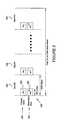
- FIG. 1is an illustration of a wireless communications network according to an embodiment of the present subject matter.
- FIG. 2is an illustration of the structure of a synchronization channel radio frame according to an embodiment of the present subject matter.
- FIGS. 3A and 3Billustrate examples of detection of downlink slot markers according to embodiments of the present subject matter.
- FIG. 4is an illustration of the timing relationships between downlink physical channels according to an embodiment of the present subject matter.
- FIG. 5is an illustration of an example of a non-coherent correlation result having a delay of one slot according to an embodiment of the present subject matter.
- FIG. 6is an illustration of a folding of the non-coherent correlation result of FIG. 5 .
- FIG. 7is an illustration of an estimation of round trip propagation delay according to an embodiment of the present subject matter.
- FIG. 8is an algorithm according to one embodiment of the present subject matter.
- FIG. 1is an illustration of a wireless communications network according to an embodiment of the present subject matter.
- a wireless communications network 100 or systemis shown.
- the networkmay be a Global System for Mobile Communication (“GSM”) network, a Time Division Multiple Access (“TDMA”) network, Code Division Multiple Access (“CDMA”) network, a UMTS network, a Worldwide Interoperability for Microwave Access (“WiMax”) network, a WiFi network, networks utilizing Evolution-Data Optimized (“EDVO”), CDMA2000 network, 1 times Radio Transmission Technology (“1 ⁇ RTT”) standards or another equivalent network.
- GSMGlobal System for Mobile Communication
- TDMATime Division Multiple Access
- CDMACode Division Multiple Access
- WiMaxWorldwide Interoperability for Microwave Access
- WiFiWireless Fidelity
- EDVOEvolution-Data Optimized
- CDMA2000Code Division Multiple Access
- 1 ⁇ RTTRadio Transmission Technology
- LMULocation measurement units
- the wireless network 100serves mobile stations or devices 120 , 122 within reception range of at least one of the base stations 102 - 106 .
- Mobile stations 120 , 122may include cellular telephones, text messaging devices, computers, portable computers, vehicle locating devices, vehicle security devices, communication devices, wireless transceivers or other devices with a wireless communications interface.
- Base station transceivers 102 - 106also commonly referred to simply as base stations, are connected to a central entity or central network unit 130 .
- the central entity 130may be a base station controller (“BSC”) in a base station subsystem (“BSS”), a Radio Network Controller (“RNC”) in a Radio Access Network (“RAN”), or, for GSM, General Packet Radio Service (“GPRS”) or UMTS system, a serving mobile location center (“SMLC”) or an equivalent.
- BSCbase station controller
- RNCRadio Network Controller
- RANRadio Access Network
- GSMGlobal System for Mobile communications
- GPRSGeneral Packet Radio Service
- UMTSserving mobile location center
- SMLCserving mobile location center
- the connection from each base station to a BSC, SMLC or other central network entitymay employ a direct transmission link, e.g., a wired connection, microwave link, Ethernet connection, and the like, or may be employed by one or more intermediate entities, e.g., an intermediate BSC in the case of a connection from a BTS to an SMLC for GSM.
- Each mobile station 120 , 122may periodically measure the transmission timing difference between pairs of base stations 102 - 106 .
- a mobile station 120may measure the difference in transmission timing for communication from its serving base station 102 and from one or more neighboring base stations, e.g., 106 and/or 103 .
- the mobile station 120searches for a cell and determines the downlink scrambling code and frame synchronization of that cell.
- the cell searchis typically carried out in three steps, slot synchronization, frame synchronization and code-group identification, and scrambling-code identification.
- the mobile station 120uses a downlink signal commonly referred to as the Synchronization Channel (“SCH”).
- FIG. 2is an illustration of the structure of a synchronization channel radio frame according to an embodiment of the present subject matter.
- the SCH 200consists of two sub channels, the Primary SCH 210 and the Secondary SCH 220 .
- the Primary and Secondary SCH 210 , 220are divided into fifteen slots 230 , each having a length of 2560 chips.
- the Primary SCH 200transmits a modulated code having a length of 256 chips and transmits the Primary Synchronization Code (“PSC”) 240 (denoted as c p ) once every downlink slot 230 .
- PSCPrimary Synchronization Code
- the PSC 240is the same for every cell in the system and does not have any complex scrambling thereon.
- the Secondary SCH 220consists of repeatedly transmitting a sequence of modulated codes having a length of 256 chips.
- Secondary Synchronization Codes (“SSC”) 250are transmitted in parallel with the Primary SCH 210 .
- Each SSC 250may be selected from a set of sixteen different codes having a length of 256 chips.
- This sequence on the Secondary SCH 220indicates to which of the code groups a cell's downlink scrambling code belongs.
- the primary and secondary synchronization codesare modulated by the symbol a shown in FIG. 2 indicating the presence/absence of space time block coding based transmit antenna diversity (“STTD”) encoding on the Primary Common Control Physical Channel (“P-CCPCH”) and is listed in Table 1 below.
- STTDspace
- the P-CCPCHis a fixed rate (30 kbps, SF-256) downlink physical channel used to carry the broadcast channel (“BCH”).
- BCHbroadcast channel
- the mobile stationutilizes the SCH's primary synchronization code to acquire slot synchronization to a cell. This is typically done with a single matched filter or any similar device matched to the PSC. The slot timing of the cell may then be obtained by detecting peaks in the matched filter output.
- the PSC or C pscis constructed as a generalized hierarchical Golay sequence.
- the PSCgenerally exhibits good aperiodic auto correlation properties.
- FIGS. 3A and 3Billustrate an exemplary detection of downlink slot markers according to embodiments of the present subject matter.
- UTRAUMTS terrestrial radio access
- FIG. 4is an illustration of the timing relationships between downlink physical channels according to an embodiment of the present subject matter.
- the P-CCPCH 410on which the cell system frame number (“SFN”) is transmitted, is used as the timing reference for all the physical channels, directly for downlink and indirectly for uplink.
- the Primary SCH 210 , the Secondary SCH 220 , the Primary and Secondary CPICH 420 , and the P-CCPCH 410all have identical frame timings.
- the three sectors of a base stationare generally locked to a common reference clock or frequency source. Therefore, the relative time differences of the downlink frames of the three sectors are constant, although the reference clock may itself drift.
- the time difference of the downlink frames in different sectors at the same siteis generally a multiple of 256 chips.
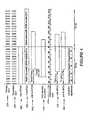
- Table 2 belowprovides a definition of some synchronization parameters and clarifies the timing relationship of the sectors. The parameters listed in Table 2 are not intended to be an exhaustive list as Section 5 of TS 25.402 provides a more comprehensive list, and thus should not limit the scope of the claimed appended herewith.
- the mobile station 120has the capability to follow the frame timing change of the serving site (Node B).
- the uplink DPCCH/DPDCH frame transmissiontakes approximately T o chips after the reception of the first detected path (in time) of the corresponding downlink DPCCH/DPDCH frame from the reference cell.
- T ois a constant defined to be 1024 chips.
- the uplink DPCCH/DPDCH frame transmissiontakes place approximately T o chips after the reception of the first detected or significant path (in time) of the corresponding downlink DPCCH/DPDCH or F-DPCH frame.
- the mobile station initial transmission timing error T ois maintained within ⁇ 1.5 chips at the mobile station.
- the reference point for the mobile station initial transmit timing control requirementis the time when the first detected path (in time) of the corresponding downlink DPCCH/DPDCH frame is received from the reference cell plus T o chips.
- the reference cellis the one the mobile station has in the active set. The cell, which is selected as a reference cell, remains as a reference cell even if other cells are added to the active set.
- the mobile stationadjusts its respective transmit timing no later than the time when the whole active set update message is available at the mobile station.
- the mobile stationis also capable of changing the transmission timing according to the received downlink DPCCH/DPDCH frame.
- the offsets between the DPCHs of the three sectors of a base stationare multiples of 256 chips
- the offset between the start of DPCH and SCHis a multiple of 256 chips
- Exemplary LMUsmay be collocated with the serving base station.
- an exemplary LMUmonitors a neighboring cells' downlink signals (which transmit the same SCH utilized as reference for correlation)
- spurious peaksmay be seen in the correlation result if the downlink signals of the neighboring sectors are strong.
- Embodiments of the present subject mattermay thus correlate for a delay of 256 chips and then add all correlation results non-coherently to thereby align the DL slot markers of the three collocated sectors.
- the resultant peak for the collocated sitewill be enhanced, and the peaks for the neighboring sites (sectors of different base stations) will not line up because the peaks for the neighboring sites are not frequency locked to each other and also because the signal propagation is different in each case.
- FIG. 5illustrates an exemplary non-coherent correlation result having a delay of one slot according to an embodiment of the present subject matter.
- a non-coherent correlation result 500 with a delay of 5120 samplesi.e., 2560 chips or one slot
- the circles 510 in the plotindicate 512-sample (256-chip) jumps from the highest peak found.
- the peaks on the 1st and 8th markers 512 , 514are from the collocated sectors.
- the two other weak peaks, between 5th and 6th markers 516 and 8th and 9th markers 518are from the downlink signals of neighboring cells.
- FIG. 6is an illustration of a folding of the non-coherent correlation result of FIG. 5 .
- a prominent peak 610may be identified corresponding to only the peak from the collocated site.
- spurious peaks detected at an exemplary LMU from the downlink signals of neighboring cells 516 , 518may be faded and the DL slot markers for the collocated sectors 512 , 514 may be enhanced providing the prominent peak 610 illustrated in FIG. 6 . Therefore, exemplary embodiments of the present subject matter may thus correlate for a delay of 256 chips and then add all correlation results non-coherently, i.e., folding, to thereby align the DL slot markers of collocated sectors.
- FIG. 7is an illustration of an estimation of round trip propagation delay according to an embodiment of the present subject matter.
- the time stamp of an uplink signal 710 during the reverse collection period 711is represented as t UL and measured in seconds.
- the collector thread, at the end of reverse collection period,may tune to the downlink frequency and collect downlink samples and the time stamp for the second collection period 721 may also be noted.
- the time stamp of a downlink signal 720 during the forward collection period 721is represented as t DL and measured in seconds.
- the uplink time of arrival (“UL TOA”) frame marker 712is measured n UL samples 714 from t UL .
- UL TOAuplink time of arrival
- the downlink marker 722(e.g., slot marker folded to 512 samples) is measured n DL samples 724 from t DL . To estimate the round trip propagation delay 750 (n round — trip ), the downlink marker 722 must be shifted.
- An exemplary sample rate Rmay be, but is not limited to 7.68 MHz.
- n round — tripmay not be reliable.
- the range ring radiuswill be zero if n round — trip is greater than 500 samples.
- the range ringis generally applicable for the serving site which governs the mobile station timing.
- the serving sector identifier(UC-ID) is generally available in the respective network tipping information list. While the DTP interface does not provide this information, the following steps may be taken to resolve such issues: change the DTP-GCS interface to include all of the primary scrambling code with their relative strengths; populate the “Pilot Offset” fields of NMS with the primary scrambling code of the UMTS sectors during DTP based testing; and/or GCS will match the strongest primary scrambling code with the database and will decide which site is the serving one.
- all the range rings smaller than 1 kmmay be passed to a processor and the processor will filter and/or determine which range ring to utilize based upon information available thereto, including but not limited to, information arriving through a hybrid combination of location technologies such as triangulation, trilateration, time difference of arrival, GPS, angle of arrival, Cell-ID, signal strength, assisted-GPS, Enhanced Observed Time Difference, Advanced Forward Link Trilateration, etc.
- range ringsmay be utilized when one or more sites detect TOA.
- a range ring solution for GSMgenerally requires keeping track of network deployment information whereas the solution for UMTS does not require knowledge of network configuration such as base station timing offsets, etc.
- FIG. 8is an algorithm according to one embodiment of the present subject matter.
- a method for determining an approximate range from a LMU to a mobile deviceis provided.
- Exemplary communications networks employing an LMU according to embodiments of the present subject mattermay be a UMTS network, WiMax network, GSM network, WiFi network, CDMA network or a network utilizing Evolution-Data Optimized (“EDVO”), IS-95, CDMA2000, and/or 1 time Radio Transmission Technology (“1 ⁇ RTT”) standards.
- EDVOEvolution-Data Optimized
- 1 ⁇ RTT1 time Radio Transmission Technology
- An exemplary mobile devicemay be, but is not limited to a cellular telephone, text messaging device, computer, portable computer, vehicle locating device, vehicle security device, communication device, and wireless transceiver.
- an uplink frame markeris determined from the uplink signal.
- a down link signal from a base station serving the mobile devicemay be received at the LMU and a downlink slot marker determined from the downlink signal in step 840 .
- the LMU and the serving base stationmay be co-located.
- the downlink signalmay be from a sector other than the sector serving the mobile device.
- the downlink slot markermay be, but is not limited to, a modulo 512 multiple. Further, the downlink slot marker may be a function of equation (3) provided above.
- the round trip propagation delaymay be determined in step 850 based upon the uplink frame marker and the downlink slot marker.
- an approximate range from the LMU to the mobile devicemay be determined as a function of the round trip propagation delay.
- the approximate rangemay be determined as a function of signals received from one or more LMUs installed throughout an exemplary communications network.
- step 820may also include determining a first time stamp for the uplink signal and determining a number of samples between the first time stamp and the uplink frame marker.
- step 820may also include determining a first time stamp for the uplink signal and determining a number of samples between the first time stamp and the uplink frame marker.
- step 820may also include determining a second time stamp for the downlink signal and determine a number of samples between the second time stamp and the downlink slot marker.
- the round trip propagation delaymay be determined by shifting the downlink slot marker a number of samples such that the number of samples between the uplink frame marker and the downlink slot marker is less than 512, and determining the number of samples between the uplink frame marker and the shifted downlink slot marker.
- an approximate rangemay be determined from the LMU to the mobile device by multiplying the number of samples between the uplink frame marker and the shifted downlink slot marker by a predetermined number.
- the predetermined numbermay be, but is not limited to, 19.53125.
- the number of samples between the uplink frame marker and the shifted downlink slot markermay be determined by a non-limiting exemplary sample rate of 7.68 MHz.
- FIGS. 1-8As shown by the various configurations and embodiments illustrated in FIGS. 1-8 , a system and method for ranging in a communications network have been described.
Landscapes
- Engineering & Computer Science (AREA)
- Computer Networks & Wireless Communication (AREA)
- Signal Processing (AREA)
- Mobile Radio Communication Systems (AREA)
Abstract
Description
| TABLE 1 | ||
| P-CCPCH STTD encoded | a = +1 | |
| P-CCPCH not STTD encoded | a = −1 | |
Cpsc=(1+j)*<a,a,a,−a,−a,a,−a,−a,a,a,a,−a,a,−a,a,a>, (1)
where a=<x1, x2, x3, . . . , x16>=<1, 1, 1, 1, 1, 1, −1, −1, 1, −1, 1, −1, 1, −1, −1, 1>.
| TABLE 2 | ||
| BFN | Node B Frame Number counter. This is the | |
| Node B common frame number counter. | ||
| Range: 0 . . . 4095 frames. | ||
| SFN | Cell SFN counter. SFN is sent on BCH. | |
| SFN is used for paging groups and system | ||
| information scheduling, etc. In FDD SFN = | ||
| BFN adjusted with T_cell. | ||
| Range: 0 . . . 4095 frames | ||
| [FDD - T_cell] | T_cell represents the Timing delay used for | |
| defining the start of SCH, CPICH and the | ||
| DL Scrambling Code(s) in a cell relative | ||
| BFN. The main purpose is to avoid having | ||
| overlapping SCHs in different cells | ||
| belonging to the same Node B. A nSCH | ||
| burst is 256 chips long. SFN in a cell is | ||
| delayed T_cell relative BFN. Resolution: | ||
| 256 chips. Range: 0 . . . 9 × 256 chips. | ||
nDL
where
0<=nUL−((tDL−tUL)R+nDL−512N)<512 (3)
An exemplary sample rate R may be, but is not limited to 7.68 MHz.
nround
where nround
rrange
Claims (29)
0≦nUL−((tDL−tUL)R+nDL−512N) <512,
0<nUL−((tDL−tUL)R1+nDL−256(R2)N)<256(R2),
Priority Applications (1)
| Application Number | Priority Date | Filing Date | Title |
|---|---|---|---|
| US13/396,256US8315648B2 (en) | 2007-11-14 | 2012-02-14 | Ranging in UMTS networks |
Applications Claiming Priority (2)
| Application Number | Priority Date | Filing Date | Title |
|---|---|---|---|
| US11/984,207US8170585B2 (en) | 2007-11-14 | 2007-11-14 | Ranging in UMTS networks |
| US13/396,256US8315648B2 (en) | 2007-11-14 | 2012-02-14 | Ranging in UMTS networks |
Related Parent Applications (1)
| Application Number | Title | Priority Date | Filing Date |
|---|---|---|---|
| US11/984,207ContinuationUS8170585B2 (en) | 2007-11-14 | 2007-11-14 | Ranging in UMTS networks |
Publications (2)
| Publication Number | Publication Date |
|---|---|
| US20120142374A1 US20120142374A1 (en) | 2012-06-07 |
| US8315648B2true US8315648B2 (en) | 2012-11-20 |
Family
ID=40624189
Family Applications (2)
| Application Number | Title | Priority Date | Filing Date |
|---|---|---|---|
| US11/984,207Expired - Fee RelatedUS8170585B2 (en) | 2007-11-14 | 2007-11-14 | Ranging in UMTS networks |
| US13/396,256ActiveUS8315648B2 (en) | 2007-11-14 | 2012-02-14 | Ranging in UMTS networks |
Family Applications Before (1)
| Application Number | Title | Priority Date | Filing Date |
|---|---|---|---|
| US11/984,207Expired - Fee RelatedUS8170585B2 (en) | 2007-11-14 | 2007-11-14 | Ranging in UMTS networks |
Country Status (1)
| Country | Link |
|---|---|
| US (2) | US8170585B2 (en) |
Cited By (2)
| Publication number | Priority date | Publication date | Assignee | Title |
|---|---|---|---|---|
| US20120263152A1 (en)* | 2009-01-13 | 2012-10-18 | Adc Telecommunications, Inc. | Systems and methods for ip communication over a distributed antenna system transport |
| USRE47466E1 (en)* | 2009-01-13 | 2019-06-25 | Commscope Technologies Llc | Systems and methods for IP communication over a distributed antenna system transport |
Families Citing this family (13)
| Publication number | Priority date | Publication date | Assignee | Title |
|---|---|---|---|---|
| US8170585B2 (en)* | 2007-11-14 | 2012-05-01 | Andrew, Llc | Ranging in UMTS networks |
| US8116784B2 (en)* | 2007-12-13 | 2012-02-14 | Trueposition, Inc. | Mid-call synchronization for U-TDOA and AoA location in UMTS |
| TWI469668B (en)* | 2007-12-31 | 2015-01-11 | Interdigital Patent Holdings | Method and device for wireless link synchronization and power control in CELL_FACH state |
| US8451819B2 (en)* | 2008-03-26 | 2013-05-28 | Qualcomm Incorporated | Methods and apparatus for uplink frame synchronization in a subscriber station |
| JP2009260768A (en)* | 2008-04-18 | 2009-11-05 | Kyocera Corp | Mobile communication system, mobile station device, base station device, and handover method |
| JP5285497B2 (en)* | 2009-03-12 | 2013-09-11 | 株式会社エヌ・ティ・ティ・ドコモ | Mobile communication method and radio base station |
| US20100304744A1 (en)* | 2009-05-29 | 2010-12-02 | Qualcomm Incorporated | Method and apparatus for performing searches with multiple receive diversity (rxd) search modes |
| WO2011019357A1 (en)* | 2009-08-14 | 2011-02-17 | Andrew Llc | System and method for hybrid location in a wimax network |
| US20110294493A1 (en)* | 2009-11-25 | 2011-12-01 | Qualcomm Incorporated | Modulating cell information on a physical channel |
| US8331955B2 (en)* | 2010-12-28 | 2012-12-11 | Trueposition, Inc. | Robust downlink frame synchronization schemes in CDMA wireless networks for geo-location |
| US20130143598A1 (en)* | 2011-12-02 | 2013-06-06 | Andrew, Llc | Umts proximity detection with uplink and downlink signals |
| US8897813B2 (en)* | 2012-02-03 | 2014-11-25 | Andrew Llc | LTE user equipment positioning system and method |
| CN109815300B (en)* | 2018-12-13 | 2021-06-29 | 北京邮电大学 | A vehicle positioning method |
Citations (7)
| Publication number | Priority date | Publication date | Assignee | Title |
|---|---|---|---|---|
| US6687507B2 (en)* | 2000-05-03 | 2004-02-03 | Telefonaktiebolaget Lm Ericsson (Publ) | Time of arrival estimation for edge/GSM |
| US7031722B2 (en)* | 1999-05-05 | 2006-04-18 | Nokia Corporation | Method for positioning a mobile station |
| US7110774B1 (en)* | 2000-10-27 | 2006-09-19 | Intel Corporation | Dual mode uplink/downlink location measurement and multi-protocol location measurement |
| US20080130555A1 (en)* | 2006-11-30 | 2008-06-05 | Amit Kalhan | Apparatus, system and method for managing wireless local area network service to a multi-mode portable communication device |
| US7505774B1 (en)* | 2000-09-29 | 2009-03-17 | Intel Corporation | Repetitive paging from a wireless data base station having a smart antenna system |
| US7680501B2 (en)* | 2004-05-12 | 2010-03-16 | Nokia Corporation | Locating mobile terminals |
| US8170585B2 (en)* | 2007-11-14 | 2012-05-01 | Andrew, Llc | Ranging in UMTS networks |
Family Cites Families (125)
| Publication number | Priority date | Publication date | Assignee | Title |
|---|---|---|---|---|
| US3150372A (en) | 1959-06-23 | 1964-09-22 | Motorola Inc | Computing system |
| US3659085A (en) | 1970-04-30 | 1972-04-25 | Sierra Research Corp | Computer determining the location of objects in a coordinate system |
| US4728959A (en)* | 1986-08-08 | 1988-03-01 | Ventana Sciences Inc. | Direction finding localization system |
| US4814751A (en) | 1987-02-27 | 1989-03-21 | Wildlife Materials, Inc. | Patient tracking system |
| US4845504A (en) | 1987-04-08 | 1989-07-04 | M/A-Com, Inc. | Mobile radio network for nationwide communications |
| US4891650A (en) | 1988-05-16 | 1990-01-02 | Trackmobile Inc. | Vehicle location system |
| US5056106A (en) | 1990-08-02 | 1991-10-08 | Wang James J | Golf course ranging and direction-finding system using spread-spectrum radiolocation techniques |
| US5218618A (en) | 1990-11-07 | 1993-06-08 | Hughes Aircraft Company | Cellular telephone service using spread spectrum transmission |
| US5365544A (en) | 1990-12-05 | 1994-11-15 | Interdigital Technology Corporation | CDMA communications and geolocation system and method |
| US5506864A (en) | 1990-12-05 | 1996-04-09 | Interdigital Technology Corporation | CDMA communications and geolocation system and method |
| JPH0567996A (en) | 1991-09-09 | 1993-03-19 | Nec Corp | Automobile telephone set system |
| US5515419A (en) | 1992-06-01 | 1996-05-07 | Trackmobile | Tracking system and method for tracking a movable object carrying a cellular phone unit, and integrated personal protection system incorporating the tracking system |
| US5592180A (en) | 1992-08-20 | 1997-01-07 | Nexus1994 Limited | Direction finding and mobile location system for trunked mobile radio systems |
| US5372144A (en) | 1992-12-01 | 1994-12-13 | Scimed Life Systems, Inc. | Navigability improved guidewire construction and method of using same |
| US5465289A (en) | 1993-03-05 | 1995-11-07 | E-Systems, Inc. | Cellular based traffic sensor system |
| US5317323A (en) | 1993-03-05 | 1994-05-31 | E-Systems, Inc. | Passive high accuracy geolocation system and method |
| US5327144A (en)* | 1993-05-07 | 1994-07-05 | Associated Rt, Inc. | Cellular telephone location system |
| AU7173694A (en) | 1993-06-25 | 1995-01-17 | Omniplex, Inc. | Determination of location using time-synchronized cell site transmissions |
| US5506863A (en) | 1993-08-25 | 1996-04-09 | Motorola, Inc. | Method and apparatus for operating with a hopping control channel in a communication system |
| US5404376A (en) | 1993-09-09 | 1995-04-04 | Ericsson-Ge Mobile Communications Inc. | Navigation assistance for call handling in mobile telephone systems |
| US5519760A (en) | 1994-06-22 | 1996-05-21 | Gte Laboratories Incorporated | Cellular network-based location system |
| US5512908A (en) | 1994-07-08 | 1996-04-30 | Lockheed Sanders, Inc. | Apparatus and method for locating cellular telephones |
| US5614914A (en) | 1994-09-06 | 1997-03-25 | Interdigital Technology Corporation | Wireless telephone distribution system with time and space diversity transmission for determining receiver location |
| US5594776A (en)* | 1994-09-14 | 1997-01-14 | Ericsson Inc. | Efficient paging system |
| US5602903A (en) | 1994-09-28 | 1997-02-11 | Us West Technologies, Inc. | Positioning system and method |
| US5959580A (en)* | 1994-11-03 | 1999-09-28 | Ksi Inc. | Communications localization system |
| GB9508884D0 (en) | 1995-05-02 | 1995-06-21 | Telecom Sec Cellular Radio Ltd | Cellular radio system |
| US5508708A (en) | 1995-05-08 | 1996-04-16 | Motorola, Inc. | Method and apparatus for location finding in a CDMA system |
| US5825887A (en) | 1995-12-28 | 1998-10-20 | Trimble Navigation Limited | Transmitting and receiving apparatus for full code correlation operation under encryption for satellite positioning system |
| US6047192A (en)* | 1996-05-13 | 2000-04-04 | Ksi Inc. | Robust, efficient, localization system |
| US6108555A (en)* | 1996-05-17 | 2000-08-22 | Ksi, Inc. | Enchanced time difference localization system |
| US6717014B1 (en)* | 1996-06-28 | 2004-04-06 | Fmc Corporation | Processes for preparing haloamines and tertiary aminoalkylorganometallic compounds |
| US5675344A (en) | 1996-06-28 | 1997-10-07 | Motorola, Inc. | Method and apparatus for locating a mobile station in a spread spectrum communication system |
| US5870029A (en) | 1996-07-08 | 1999-02-09 | Harris Corporation | Remote mobile monitoring and communication system |
| WO1998009385A2 (en) | 1996-08-29 | 1998-03-05 | Cisco Technology, Inc. | Spatio-temporal processing for communication |
| US5945949A (en)* | 1997-01-13 | 1999-08-31 | Lucent Technologies Inc. | Mobile station position determination in a wireless communication system |
| US6233459B1 (en) | 1997-04-10 | 2001-05-15 | The Atlantis Company, Limited, Japan | System for providing Geolocation of a mobile transceiver |
| US5973643A (en) | 1997-04-11 | 1999-10-26 | Corsair Communications, Inc. | Method and apparatus for mobile emitter location |
| US5920278A (en) | 1997-05-28 | 1999-07-06 | Gregory D. Gibbons | Method and apparatus for identifying, locating, tracking, or communicating with remote objects |
| US6101178A (en)* | 1997-07-10 | 2000-08-08 | Ksi Inc. | Pseudolite-augmented GPS for locating wireless telephones |
| US5987329A (en) | 1997-07-30 | 1999-11-16 | Ericsson Inc | System and method for mobile telephone location measurement using a hybrid technique |
| US5952969A (en) | 1997-08-18 | 1999-09-14 | Telefonakiebolaget L M Ericsson (Publ) | Method and system for determining the position of mobile radio terminals |
| US6011974A (en)* | 1997-09-23 | 2000-01-04 | Telefonaktiebolaget L M Ericsson (Publ) | Method and system for determining position of a cellular mobile terminal |
| FR2771517B1 (en) | 1997-11-27 | 2001-12-14 | Dassault Electronique | ELECTRO-OPTICAL DEVICE, PARTICULARLY FOR OPTICAL DISTRIBUTION |
| US6097959A (en) | 1998-01-29 | 2000-08-01 | Ericsson Inc. | System and method for accurate positioning of mobile terminals |
| US6201499B1 (en) | 1998-02-03 | 2001-03-13 | Consair Communications | Time difference of arrival measurement system |
| US6014102A (en) | 1998-04-17 | 2000-01-11 | Motorola, Inc. | Method and apparatus for calibrating location finding equipment within a communication system |
| US6075826A (en)* | 1998-05-13 | 2000-06-13 | Comsat Corporation | Method and apparatus for obtaining initial carrier and symbol phase estimates for use in synchronizing transmitting data |
| US6188351B1 (en) | 1998-08-13 | 2001-02-13 | Ericsson Inc. | Method for improving signal acquistion in a global positioning system receiver |
| US6246884B1 (en) | 1998-08-19 | 2001-06-12 | Sigmaone Communications Corporation | System and method for measuring and locating a mobile station signal in a wireless communication system |
| US6311043B1 (en) | 1998-10-27 | 2001-10-30 | Siemens Aktiengesellschaft | Method and measurement configuration for measuring the characteristics of radio channels |
| GB9828216D0 (en) | 1998-12-21 | 1999-02-17 | Northern Telecom Ltd | A downlink beamforming approach for frequency division duplex cellular systems |
| US6184829B1 (en)* | 1999-01-08 | 2001-02-06 | Trueposition, Inc. | Calibration for wireless location system |
| US6463290B1 (en)* | 1999-01-08 | 2002-10-08 | Trueposition, Inc. | Mobile-assisted network based techniques for improving accuracy of wireless location system |
| US6765531B2 (en)* | 1999-01-08 | 2004-07-20 | Trueposition, Inc. | System and method for interference cancellation in a location calculation, for use in a wireless location system |
| WO2000041402A2 (en)* | 1999-01-08 | 2000-07-13 | Trueposition, Inc. | A signal collection system |
| US6334059B1 (en)* | 1999-01-08 | 2001-12-25 | Trueposition, Inc. | Modified transmission method for improving accuracy for e-911 calls |
| US6646604B2 (en)* | 1999-01-08 | 2003-11-11 | Trueposition, Inc. | Automatic synchronous tuning of narrowband receivers of a wireless location system for voice/traffic channel tracking |
| US6782264B2 (en)* | 1999-01-08 | 2004-08-24 | Trueposition, Inc. | Monitoring of call information in a wireless location system |
| US6873290B2 (en)* | 1999-01-08 | 2005-03-29 | Trueposition, Inc. | Multiple pass location processor |
| US7783299B2 (en)* | 1999-01-08 | 2010-08-24 | Trueposition, Inc. | Advanced triggers for location-based service applications in a wireless location system |
| US6295455B1 (en)* | 1999-06-11 | 2001-09-25 | Telefonaktiebolaget Lm Ericsson (Publ) | Methods and arrangements for locating a mobile telecommunications station |
| US6603761B1 (en) | 1999-09-17 | 2003-08-05 | Lucent Technologies Inc. | Using internet and internet protocols to bypass PSTN, GSM map, and ANSI-41 networks for wireless telephone call delivery |
| US6553322B1 (en) | 1999-09-29 | 2003-04-22 | Honeywell International Inc. | Apparatus and method for accurate pipeline surveying |
| US6191738B1 (en) | 1999-09-30 | 2001-02-20 | Motorola, Inc. | Method and apparatus for locating a remote unit within a communication system |
| US6490456B1 (en)* | 1999-10-12 | 2002-12-03 | Lucent Technologies Inc. | Locating a mobile unit in a wireless time division multiple access system |
| US6571082B1 (en) | 1999-10-29 | 2003-05-27 | Verizon Laboratories Inc. | Wireless field test simulator |
| US6640106B2 (en) | 2001-09-20 | 2003-10-28 | Motorola, Inc. | Method and system for verifying the position of a mobile station using checkpoints |
| US6501955B1 (en) | 2000-06-19 | 2002-12-31 | Intel Corporation | RF signal repeater, mobile unit position determination system using the RF signal repeater, and method of communication therefor |
| US6366241B2 (en)* | 2000-06-26 | 2002-04-02 | Trueposition, Inc. | Enhanced determination of position-dependent signal characteristics of a wireless transmitter |
| US6771969B1 (en) | 2000-07-06 | 2004-08-03 | Harris Corporation | Apparatus and method for tracking and communicating with a mobile radio unit |
| US6407703B1 (en) | 2000-08-07 | 2002-06-18 | Lockheed Martin Corporation | Multi-platform geolocation method and system |
| FI109839B (en) | 2000-08-22 | 2002-10-15 | Nokia Corp | A method for locating a mobile station |
| US6470195B1 (en) | 2000-10-31 | 2002-10-22 | Raytheon Company | Method and apparatus for modeling a smart antenna in a network planning tool |
| US6834234B2 (en) | 2000-11-22 | 2004-12-21 | Trimble Navigation, Limited | AINS land surveyor system with reprocessing, AINS-LSSRP |
| US6952158B2 (en) | 2000-12-11 | 2005-10-04 | Kennedy Jr Joseph P | Pseudolite positioning system and method |
| US6845240B2 (en) | 2000-12-11 | 2005-01-18 | Grayson Wireless | System and method for analog cellular radio geolocation |
| US6920329B2 (en) | 2001-01-16 | 2005-07-19 | Allen Telecom | Method and system for applying wireless geolocation technology |
| WO2002085057A1 (en)* | 2001-04-06 | 2002-10-24 | Nokia Corporation | Location method and system |
| US6876859B2 (en)* | 2001-07-18 | 2005-04-05 | Trueposition, Inc. | Method for estimating TDOA and FDOA in a wireless location system |
| US6871077B2 (en) | 2001-10-09 | 2005-03-22 | Grayson Wireless | System and method for geolocating a wireless mobile unit from a single base station using repeatable ambiguous measurements |
| US6748202B2 (en)* | 2001-12-12 | 2004-06-08 | Nokia Corporation | Method, apparatus and system for synchronizing a cellular communication system to GPS time |
| US6987979B2 (en) | 2001-12-22 | 2006-01-17 | Telefonaktiebolaget Lm Ericsson (Publ) | Locating packet-switched mobile terminals using network initiated artificial cell hops |
| US6922170B2 (en) | 2002-01-24 | 2005-07-26 | Motorola, Inc. | Methods and apparatus for determining a direction of arrival in a wireless communication system |
| US6950664B2 (en) | 2002-01-24 | 2005-09-27 | Lucent Technologies Inc. | Geolocation using enhanced timing advance techniques |
| US6973320B2 (en) | 2002-04-29 | 2005-12-06 | Motorola, Inc. | Method and apparatus for locating a remote unit within a communication system |
| US8032149B2 (en) | 2002-08-29 | 2011-10-04 | Andrew Llc | Tasking and reporting method and implementation for wireless appliance location systems |
| US6996392B2 (en)* | 2002-09-03 | 2006-02-07 | Trueposition, Inc. | E911 overlay solution for GSM, for use in a wireless location system |
| US7546084B2 (en) | 2002-10-16 | 2009-06-09 | Andrew Llc | System and method of operation for network overlay geolocation system with repeaters |
| US7429951B2 (en) | 2002-10-16 | 2008-09-30 | Andrew Corporation | System and method for enhancing the accuracy of a location estimate |
| US7162252B2 (en) | 2002-12-23 | 2007-01-09 | Andrew Corporation | Method and apparatus for supporting multiple wireless carrier mobile station location requirements with a common network overlay location system |
| US7405696B2 (en) | 2003-01-31 | 2008-07-29 | Andrew Corporation | Method for calibrating and AOA location system for frequency hopping air interfaces |
| US7379019B2 (en) | 2003-01-31 | 2008-05-27 | Andrew Corporation | Method for angle of arrival determination on frequency hopping air interfaces |
| US7358898B2 (en) | 2003-01-31 | 2008-04-15 | Andrew Corporation | Method for calibrating an AOA location system for all frequencies in a frequency hopping signal |
| US6859172B2 (en) | 2003-02-17 | 2005-02-22 | Global Business Software Development Technologies, Inc. | System and method for locating a mobile phone |
| ATE442750T1 (en) | 2003-03-03 | 2009-09-15 | Andrew Llc | INDEPENDENT CAPTURE AND TRACKING OF SIGNING CHANNEL ASSIGNMENTS OF A WIRELESS COMMUNICATION SYSTEM ON COMMUNICATION LINKS |
| US20040203921A1 (en) | 2003-03-21 | 2004-10-14 | Nicholas Bromhead | Sub-sector timing advance positions determinations |
| US7429914B2 (en) | 2003-06-04 | 2008-09-30 | Andrew Corporation | System and method for CDMA geolocation |
| US7623872B2 (en) | 2003-06-24 | 2009-11-24 | Andrew Corporation | Method for sparse network deployment accuracy enhancements |
| US7123928B2 (en)* | 2003-07-21 | 2006-10-17 | Qualcomm Incorporated | Method and apparatus for creating and using a base station almanac for position determination |
| US7738836B2 (en) | 2003-09-26 | 2010-06-15 | Andrew Corporation | System and method of operation for network overlay geolocation system with repeaters using AM Golay Hadamard signatures |
| WO2005060669A2 (en) | 2003-12-19 | 2005-07-07 | Kennedy Joseph P | E-otd augmentation to u-tdoa location system |
| US7440762B2 (en)* | 2003-12-30 | 2008-10-21 | Trueposition, Inc. | TDOA/GPS hybrid wireless location system |
| KR20070114286A (en) | 2005-02-11 | 2007-11-30 | 트루포지션, 인크. | Synchronization of transmit and receive base stations |
| US7427952B2 (en)* | 2005-04-08 | 2008-09-23 | Trueposition, Inc. | Augmentation of commercial wireless location system (WLS) with moving and/or airborne sensors for enhanced location accuracy and use of real-time overhead imagery for identification of wireless device locations |
| US20060291577A1 (en)* | 2005-05-26 | 2006-12-28 | Adrian Boariu | System and method for selecting pilot tone positions in communication systems |
| US7566971B2 (en)* | 2005-05-27 | 2009-07-28 | Semiconductor Energy Laboratory Co., Ltd. | Semiconductor device and manufacturing method thereof |
| US20070117573A1 (en)* | 2005-11-04 | 2007-05-24 | Kennedy Joseph P Jr | System and method for generating geocoded data for network optimization under different network architectures and location technology conditions |
| US7689240B2 (en) | 2005-11-16 | 2010-03-30 | Trueposition, Inc. | Transmit-power control for wireless mobile services |
| US7593738B2 (en)* | 2005-12-29 | 2009-09-22 | Trueposition, Inc. | GPS synchronization for wireless communications stations |
| US20090005061A1 (en)* | 2005-12-30 | 2009-01-01 | Trueposition, Inc. | Location quality of service indicator |
| US8150421B2 (en)* | 2005-12-30 | 2012-04-03 | Trueposition, Inc. | User plane uplink time difference of arrival (U-TDOA) |
| US20070155489A1 (en)* | 2005-12-30 | 2007-07-05 | Frederic Beckley | Device and network enabled geo-fencing for area sensitive gaming enablement |
| US7920875B2 (en)* | 2006-12-01 | 2011-04-05 | Trueposition, Inc. | Subscriptionless location of wireless devices |
| US7797000B2 (en)* | 2006-12-01 | 2010-09-14 | Trueposition, Inc. | System for automatically determining cell transmitter parameters to facilitate the location of wireless devices |
| US7844280B2 (en)* | 2006-12-12 | 2010-11-30 | Trueposition, Inc. | Location of wideband OFDM transmitters with limited receiver bandwidth |
| US7616155B2 (en)* | 2006-12-27 | 2009-11-10 | Bull Jeffrey F | Portable, iterative geolocation of RF emitters |
| US7848733B2 (en)* | 2006-12-28 | 2010-12-07 | Trueposition, Inc. | Emergency wireless location system including a location determining receiver |
| US8010079B2 (en)* | 2006-12-28 | 2011-08-30 | Trueposition, Inc. | Emergency wireless location system including a wireless transceiver |
| US8478299B2 (en)* | 2007-04-06 | 2013-07-02 | Hewlett-Packard Development Company, L.P. | System and methods for obtaining coarse location for a mobile device |
| US8140092B2 (en)* | 2007-04-18 | 2012-03-20 | Trueposition, Inc. | Sparsed U-TDOA wireless location networks |
| US8045506B2 (en)* | 2007-04-18 | 2011-10-25 | Trueposition, Inc. | Sparsed U-TDOA wireless location networks |
| US8041367B2 (en)* | 2007-04-18 | 2011-10-18 | Trueposition, Inc. | Sparsed U-TDOA wireless location networks |
| US8242959B2 (en)* | 2007-04-18 | 2012-08-14 | Trueposition, Inc. | Sparsed U-TDOA wireless location networks |
| US7924224B2 (en)* | 2008-08-15 | 2011-04-12 | Trueposition, Inc. | Variable coherence integration for the location of weak signals |
- 2007
- 2007-11-14USUS11/984,207patent/US8170585B2/ennot_activeExpired - Fee Related
- 2012
- 2012-02-14USUS13/396,256patent/US8315648B2/enactiveActive
Patent Citations (7)
| Publication number | Priority date | Publication date | Assignee | Title |
|---|---|---|---|---|
| US7031722B2 (en)* | 1999-05-05 | 2006-04-18 | Nokia Corporation | Method for positioning a mobile station |
| US6687507B2 (en)* | 2000-05-03 | 2004-02-03 | Telefonaktiebolaget Lm Ericsson (Publ) | Time of arrival estimation for edge/GSM |
| US7505774B1 (en)* | 2000-09-29 | 2009-03-17 | Intel Corporation | Repetitive paging from a wireless data base station having a smart antenna system |
| US7110774B1 (en)* | 2000-10-27 | 2006-09-19 | Intel Corporation | Dual mode uplink/downlink location measurement and multi-protocol location measurement |
| US7680501B2 (en)* | 2004-05-12 | 2010-03-16 | Nokia Corporation | Locating mobile terminals |
| US20080130555A1 (en)* | 2006-11-30 | 2008-06-05 | Amit Kalhan | Apparatus, system and method for managing wireless local area network service to a multi-mode portable communication device |
| US8170585B2 (en)* | 2007-11-14 | 2012-05-01 | Andrew, Llc | Ranging in UMTS networks |
Cited By (3)
| Publication number | Priority date | Publication date | Assignee | Title |
|---|---|---|---|---|
| US20120263152A1 (en)* | 2009-01-13 | 2012-10-18 | Adc Telecommunications, Inc. | Systems and methods for ip communication over a distributed antenna system transport |
| US8958410B2 (en)* | 2009-01-13 | 2015-02-17 | Adc Telecommunications, Inc. | Systems and methods for IP communication over a distributed antenna system transport |
| USRE47466E1 (en)* | 2009-01-13 | 2019-06-25 | Commscope Technologies Llc | Systems and methods for IP communication over a distributed antenna system transport |
Also Published As
| Publication number | Publication date |
|---|---|
| US8170585B2 (en) | 2012-05-01 |
| US20120142374A1 (en) | 2012-06-07 |
| US20090124266A1 (en) | 2009-05-14 |
Similar Documents
| Publication | Publication Date | Title |
|---|---|---|
| US8315648B2 (en) | Ranging in UMTS networks | |
| US8447319B2 (en) | System and method for locating UMTS user equipment using measurement reports | |
| US8331956B2 (en) | System and method of UMTS UE location using uplink dedicated physical control channel and downlink synchronization channel | |
| US7974633B2 (en) | System and method for single sensor geolocation | |
| US20080285505A1 (en) | System and method for network timing recovery in communications networks | |
| US20080287139A1 (en) | System and method for estimating the location of a mobile station in communications networks | |
| US7797000B2 (en) | System for automatically determining cell transmitter parameters to facilitate the location of wireless devices | |
| US6999778B2 (en) | Multipath assistance for pilot phase measurement processes | |
| US8611923B2 (en) | Method and system for providing location information for emergency services | |
| US7366492B1 (en) | Method and system for mobile location detection using handoff information | |
| US6021330A (en) | Mobile location estimation in a wireless system using designated time intervals of suspended communication | |
| WO2004036935A1 (en) | Network overlay location system and method for air interface with frequency hopping | |
| WO2009065012A1 (en) | System and method for locating umts user equipment using measurement reports | |
| US20120094688A1 (en) | System and Method for Network Timing Recovery in Communications Networks | |
| US20130143598A1 (en) | Umts proximity detection with uplink and downlink signals | |
| WO2010062283A1 (en) | Ranging in umts networks | |
| Yang et al. | Design and implementation of signal processing scheme in CDMA wireless location systems | |
| HK1070523A1 (en) | Method and apparatus for estimating the position of a terminal based on identification codes for transmission sources | |
| HK1070523B (en) | Method and apparatus for estimating the position of a terminal based on identification codes for transmission sources |
Legal Events
| Date | Code | Title | Description |
|---|---|---|---|
| AS | Assignment | Owner name:JPMORGAN CHASE BANK, N.A., AS COLLATERAL AGENT, NE Free format text:PATENT SECURITY AGREEMENT (ABL);ASSIGNORS:ALLEN TELECOM LLC;ANDREW LLC;COMMSCOPE, INC. OF NORTH CAROLINA;REEL/FRAME:029013/0044 Effective date:20120904 | |
| AS | Assignment | Owner name:JPMORGAN CHASE BANK, N.A., AS COLLATERAL AGENT, NE Free format text:PATENT SECURITY AGREEMENT (TL);ASSIGNORS:ALLEN TELECOM LLC;ANDREW LLC;COMMSCOPE, INC. OF NORTH CAROLINA;REEL/FRAME:029024/0899 Effective date:20120904 | |
| STCF | Information on status: patent grant | Free format text:PATENTED CASE | |
| AS | Assignment | Owner name:COMMSCOPE TECHNOLOGIES LLC, NORTH CAROLINA Free format text:CHANGE OF NAME;ASSIGNOR:ANDREW LLC;REEL/FRAME:035286/0001 Effective date:20150301 | |
| AS | Assignment | Owner name:WILMINGTON TRUST, NATIONAL ASSOCIATION, AS COLLATERAL AGENT, CONNECTICUT Free format text:SECURITY INTEREST;ASSIGNORS:ALLEN TELECOM LLC;COMMSCOPE TECHNOLOGIES LLC;COMMSCOPE, INC. OF NORTH CAROLINA;AND OTHERS;REEL/FRAME:036201/0283 Effective date:20150611 Owner name:WILMINGTON TRUST, NATIONAL ASSOCIATION, AS COLLATE Free format text:SECURITY INTEREST;ASSIGNORS:ALLEN TELECOM LLC;COMMSCOPE TECHNOLOGIES LLC;COMMSCOPE, INC. OF NORTH CAROLINA;AND OTHERS;REEL/FRAME:036201/0283 Effective date:20150611 | |
| FPAY | Fee payment | Year of fee payment:4 | |
| AS | Assignment | Owner name:REDWOOD SYSTEMS, INC., NORTH CAROLINA Free format text:RELEASE OF SECURITY INTEREST PATENTS (RELEASES RF 036201/0283);ASSIGNOR:WILMINGTON TRUST, NATIONAL ASSOCIATION;REEL/FRAME:042126/0434 Effective date:20170317 Owner name:COMMSCOPE TECHNOLOGIES LLC, NORTH CAROLINA Free format text:RELEASE OF SECURITY INTEREST PATENTS (RELEASES RF 036201/0283);ASSIGNOR:WILMINGTON TRUST, NATIONAL ASSOCIATION;REEL/FRAME:042126/0434 Effective date:20170317 Owner name:ALLEN TELECOM LLC, NORTH CAROLINA Free format text:RELEASE OF SECURITY INTEREST PATENTS (RELEASES RF 036201/0283);ASSIGNOR:WILMINGTON TRUST, NATIONAL ASSOCIATION;REEL/FRAME:042126/0434 Effective date:20170317 Owner name:COMMSCOPE, INC. OF NORTH CAROLINA, NORTH CAROLINA Free format text:RELEASE OF SECURITY INTEREST PATENTS (RELEASES RF 036201/0283);ASSIGNOR:WILMINGTON TRUST, NATIONAL ASSOCIATION;REEL/FRAME:042126/0434 Effective date:20170317 | |
| AS | Assignment | Owner name:REDWOOD SYSTEMS, INC., NORTH CAROLINA Free format text:RELEASE BY SECURED PARTY;ASSIGNOR:JPMORGAN CHASE BANK, N.A.;REEL/FRAME:048840/0001 Effective date:20190404 Owner name:COMMSCOPE TECHNOLOGIES LLC, NORTH CAROLINA Free format text:RELEASE BY SECURED PARTY;ASSIGNOR:JPMORGAN CHASE BANK, N.A.;REEL/FRAME:048840/0001 Effective date:20190404 Owner name:ANDREW LLC, NORTH CAROLINA Free format text:RELEASE BY SECURED PARTY;ASSIGNOR:JPMORGAN CHASE BANK, N.A.;REEL/FRAME:048840/0001 Effective date:20190404 Owner name:COMMSCOPE, INC. OF NORTH CAROLINA, NORTH CAROLINA Free format text:RELEASE BY SECURED PARTY;ASSIGNOR:JPMORGAN CHASE BANK, N.A.;REEL/FRAME:048840/0001 Effective date:20190404 Owner name:ALLEN TELECOM LLC, ILLINOIS Free format text:RELEASE BY SECURED PARTY;ASSIGNOR:JPMORGAN CHASE BANK, N.A.;REEL/FRAME:048840/0001 Effective date:20190404 Owner name:COMMSCOPE TECHNOLOGIES LLC, NORTH CAROLINA Free format text:RELEASE BY SECURED PARTY;ASSIGNOR:JPMORGAN CHASE BANK, N.A.;REEL/FRAME:049260/0001 Effective date:20190404 Owner name:ALLEN TELECOM LLC, ILLINOIS Free format text:RELEASE BY SECURED PARTY;ASSIGNOR:JPMORGAN CHASE BANK, N.A.;REEL/FRAME:049260/0001 Effective date:20190404 Owner name:REDWOOD SYSTEMS, INC., NORTH CAROLINA Free format text:RELEASE BY SECURED PARTY;ASSIGNOR:JPMORGAN CHASE BANK, N.A.;REEL/FRAME:049260/0001 Effective date:20190404 Owner name:COMMSCOPE, INC. OF NORTH CAROLINA, NORTH CAROLINA Free format text:RELEASE BY SECURED PARTY;ASSIGNOR:JPMORGAN CHASE BANK, N.A.;REEL/FRAME:049260/0001 Effective date:20190404 Owner name:ANDREW LLC, NORTH CAROLINA Free format text:RELEASE BY SECURED PARTY;ASSIGNOR:JPMORGAN CHASE BANK, N.A.;REEL/FRAME:049260/0001 Effective date:20190404 | |
| AS | Assignment | Owner name:JPMORGAN CHASE BANK, N.A., NEW YORK Free format text:ABL SECURITY AGREEMENT;ASSIGNORS:COMMSCOPE, INC. OF NORTH CAROLINA;COMMSCOPE TECHNOLOGIES LLC;ARRIS ENTERPRISES LLC;AND OTHERS;REEL/FRAME:049892/0396 Effective date:20190404 Owner name:WILMINGTON TRUST, NATIONAL ASSOCIATION, AS COLLATE Free format text:PATENT SECURITY AGREEMENT;ASSIGNOR:COMMSCOPE TECHNOLOGIES LLC;REEL/FRAME:049892/0051 Effective date:20190404 Owner name:JPMORGAN CHASE BANK, N.A., NEW YORK Free format text:TERM LOAN SECURITY AGREEMENT;ASSIGNORS:COMMSCOPE, INC. OF NORTH CAROLINA;COMMSCOPE TECHNOLOGIES LLC;ARRIS ENTERPRISES LLC;AND OTHERS;REEL/FRAME:049905/0504 Effective date:20190404 Owner name:WILMINGTON TRUST, NATIONAL ASSOCIATION, AS COLLATERAL AGENT, CONNECTICUT Free format text:PATENT SECURITY AGREEMENT;ASSIGNOR:COMMSCOPE TECHNOLOGIES LLC;REEL/FRAME:049892/0051 Effective date:20190404 | |
| MAFP | Maintenance fee payment | Free format text:PAYMENT OF MAINTENANCE FEE, 8TH YEAR, LARGE ENTITY (ORIGINAL EVENT CODE: M1552); ENTITY STATUS OF PATENT OWNER: LARGE ENTITY Year of fee payment:8 | |
| AS | Assignment | Owner name:WILMINGTON TRUST, DELAWARE Free format text:SECURITY INTEREST;ASSIGNORS:ARRIS SOLUTIONS, INC.;ARRIS ENTERPRISES LLC;COMMSCOPE TECHNOLOGIES LLC;AND OTHERS;REEL/FRAME:060752/0001 Effective date:20211115 | |
| AS | Assignment | Owner name:COMMSCOPE, INC. OF NORTH CAROLINA, NORTH CAROLINA Free format text:PARTIAL RELEASE OF ABL SECURITY INTEREST;ASSIGNOR:JPMORGAN CHASE BANK, N.A.;REEL/FRAME:060649/0305 Effective date:20220712 Owner name:ARRIS ENTERPRISES LLC, NORTH CAROLINA Free format text:PARTIAL RELEASE OF ABL SECURITY INTEREST;ASSIGNOR:JPMORGAN CHASE BANK, N.A.;REEL/FRAME:060649/0305 Effective date:20220712 Owner name:COMMSCOPE TECHNOLOGIES LLC, NORTH CAROLINA Free format text:PARTIAL RELEASE OF ABL SECURITY INTEREST;ASSIGNOR:JPMORGAN CHASE BANK, N.A.;REEL/FRAME:060649/0305 Effective date:20220712 Owner name:COMMSCOPE, INC. OF NORTH CAROLINA, NORTH CAROLINA Free format text:PARTIAL RELEASE OF TERM LOAN SECURITY INTEREST;ASSIGNOR:JPMORGAN CHASE BANK, N.A.;REEL/FRAME:060649/0286 Effective date:20220712 Owner name:ARRIS ENTERPRISES LLC, NORTH CAROLINA Free format text:PARTIAL RELEASE OF TERM LOAN SECURITY INTEREST;ASSIGNOR:JPMORGAN CHASE BANK, N.A.;REEL/FRAME:060649/0286 Effective date:20220712 Owner name:COMMSCOPE TECHNOLOGIES LLC, NORTH CAROLINA Free format text:PARTIAL RELEASE OF TERM LOAN SECURITY INTEREST;ASSIGNOR:JPMORGAN CHASE BANK, N.A.;REEL/FRAME:060649/0286 Effective date:20220712 Owner name:BISON PATENT LICENSING, LLC, GEORGIA Free format text:ASSIGNMENT OF ASSIGNORS INTEREST;ASSIGNOR:COMMSCOPE TECHNOLOGIES LLC;REEL/FRAME:060641/0312 Effective date:20220628 | |
| AS | Assignment | Owner name:COMMSCOPE, INC. OF NORTH CAROLINA, NORTH CAROLINA Free format text:PARTIAL TERMINATION AND RELEASE OF SECURITY INTEREST IN PATENTS;ASSIGNOR:WILMINGTON TRUST, NATIONAL ASSOCIATION, AS COLLATERAL AGENT;REEL/FRAME:060671/0324 Effective date:20220711 Owner name:ARRIS ENTERPRISES LLC, PENNSYLVANIA Free format text:PARTIAL TERMINATION AND RELEASE OF SECURITY INTEREST IN PATENTS;ASSIGNOR:WILMINGTON TRUST, NATIONAL ASSOCIATION, AS COLLATERAL AGENT;REEL/FRAME:060671/0324 Effective date:20220711 Owner name:COMMSCOPE TECHNOLOGIES LLC, NORTH CAROLINA Free format text:PARTIAL TERMINATION AND RELEASE OF SECURITY INTEREST IN PATENTS;ASSIGNOR:WILMINGTON TRUST, NATIONAL ASSOCIATION, AS COLLATERAL AGENT;REEL/FRAME:060671/0324 Effective date:20220711 | |
| AS | Assignment | Owner name:ARRIS ENTERPRISES LLC, GEORGIA Free format text:RELEASE BY SECURED PARTY;ASSIGNOR:WILMINGTON TRUST, NATIONAL ASSOCIATION;REEL/FRAME:063270/0220 Effective date:20221116 Owner name:COMMSCOPE, INC. OF NORTH CAROLINA, NORTH CAROLINA Free format text:RELEASE BY SECURED PARTY;ASSIGNOR:WILMINGTON TRUST, NATIONAL ASSOCIATION;REEL/FRAME:063270/0220 Effective date:20221116 Owner name:COMMSCOPE TECHNOLOGIES LLC, NORTH CAROLINA Free format text:RELEASE BY SECURED PARTY;ASSIGNOR:WILMINGTON TRUST, NATIONAL ASSOCIATION;REEL/FRAME:063270/0220 Effective date:20221116 | |
| AS | Assignment | Owner name:ARRIS ENTERPRISES LLC, GEORGIA Free format text:PARTIAL TERMINATION AND RELEASE OF SECURITY INTEREST IN PATENTS RECORDED AT R/F 060752/0001;ASSIGNOR:WILMINGTON TRUST;REEL/FRAME:063322/0209 Effective date:20221116 Owner name:COMMSCOPE, INC. OF NORTH CAROLINA, NORTH CAROLINA Free format text:PARTIAL TERMINATION AND RELEASE OF SECURITY INTEREST IN PATENTS RECORDED AT R/F 060752/0001;ASSIGNOR:WILMINGTON TRUST;REEL/FRAME:063322/0209 Effective date:20221116 Owner name:COMMSCOPE TECHNOLOGIES LLC, NORTH CAROLINA Free format text:PARTIAL TERMINATION AND RELEASE OF SECURITY INTEREST IN PATENTS RECORDED AT R/F 060752/0001;ASSIGNOR:WILMINGTON TRUST;REEL/FRAME:063322/0209 Effective date:20221116 | |
| MAFP | Maintenance fee payment | Free format text:PAYMENT OF MAINTENANCE FEE, 12TH YEAR, LARGE ENTITY (ORIGINAL EVENT CODE: M1553); ENTITY STATUS OF PATENT OWNER: LARGE ENTITY Year of fee payment:12 | |
| AS | Assignment | Owner name:RUCKUS WIRELESS, LLC (F/K/A RUCKUS WIRELESS, INC.), NORTH CAROLINA Free format text:RELEASE OF SECURITY INTEREST AT REEL/FRAME 049905/0504;ASSIGNOR:JPMORGAN CHASE BANK, N.A., AS COLLATERAL AGENT;REEL/FRAME:071477/0255 Effective date:20241217 Owner name:COMMSCOPE TECHNOLOGIES LLC, NORTH CAROLINA Free format text:RELEASE OF SECURITY INTEREST AT REEL/FRAME 049905/0504;ASSIGNOR:JPMORGAN CHASE BANK, N.A., AS COLLATERAL AGENT;REEL/FRAME:071477/0255 Effective date:20241217 Owner name:COMMSCOPE, INC. OF NORTH CAROLINA, NORTH CAROLINA Free format text:RELEASE OF SECURITY INTEREST AT REEL/FRAME 049905/0504;ASSIGNOR:JPMORGAN CHASE BANK, N.A., AS COLLATERAL AGENT;REEL/FRAME:071477/0255 Effective date:20241217 Owner name:ARRIS SOLUTIONS, INC., NORTH CAROLINA Free format text:RELEASE OF SECURITY INTEREST AT REEL/FRAME 049905/0504;ASSIGNOR:JPMORGAN CHASE BANK, N.A., AS COLLATERAL AGENT;REEL/FRAME:071477/0255 Effective date:20241217 Owner name:ARRIS TECHNOLOGY, INC., NORTH CAROLINA Free format text:RELEASE OF SECURITY INTEREST AT REEL/FRAME 049905/0504;ASSIGNOR:JPMORGAN CHASE BANK, N.A., AS COLLATERAL AGENT;REEL/FRAME:071477/0255 Effective date:20241217 Owner name:ARRIS ENTERPRISES LLC (F/K/A ARRIS ENTERPRISES, INC.), NORTH CAROLINA Free format text:RELEASE OF SECURITY INTEREST AT REEL/FRAME 049905/0504;ASSIGNOR:JPMORGAN CHASE BANK, N.A., AS COLLATERAL AGENT;REEL/FRAME:071477/0255 Effective date:20241217 |