US8315449B2 - Identification of regions of interest and extraction of time value curves in imaging procedures - Google Patents
Identification of regions of interest and extraction of time value curves in imaging proceduresDownload PDFInfo
- Publication number
- US8315449B2 US8315449B2US12/144,811US14481108AUS8315449B2US 8315449 B2US8315449 B2US 8315449B2US 14481108 AUS14481108 AUS 14481108AUS 8315449 B2US8315449 B2US 8315449B2
- Authority
- US
- United States
- Prior art keywords
- time
- enhancement
- interest
- patient
- pixel
- Prior art date
- Legal status (The legal status is an assumption and is not a legal conclusion. Google has not performed a legal analysis and makes no representation as to the accuracy of the status listed.)
- Expired - Fee Related, expires
Links
Images


Classifications
- G—PHYSICS
- G06—COMPUTING OR CALCULATING; COUNTING
- G06T—IMAGE DATA PROCESSING OR GENERATION, IN GENERAL
- G06T7/00—Image analysis
- G06T7/0002—Inspection of images, e.g. flaw detection
- G06T7/0012—Biomedical image inspection
- G—PHYSICS
- G06—COMPUTING OR CALCULATING; COUNTING
- G06F—ELECTRIC DIGITAL DATA PROCESSING
- G06F18/00—Pattern recognition
- G06F18/20—Analysing
- G06F18/23—Clustering techniques
- G06F18/232—Non-hierarchical techniques
- G06F18/2321—Non-hierarchical techniques using statistics or function optimisation, e.g. modelling of probability density functions
- G06F18/23213—Non-hierarchical techniques using statistics or function optimisation, e.g. modelling of probability density functions with fixed number of clusters, e.g. K-means clustering
- G—PHYSICS
- G06—COMPUTING OR CALCULATING; COUNTING
- G06T—IMAGE DATA PROCESSING OR GENERATION, IN GENERAL
- G06T7/00—Image analysis
- G06T7/0002—Inspection of images, e.g. flaw detection
- G06T7/0012—Biomedical image inspection
- G06T7/0014—Biomedical image inspection using an image reference approach
- G06T7/0016—Biomedical image inspection using an image reference approach involving temporal comparison
- G—PHYSICS
- G06—COMPUTING OR CALCULATING; COUNTING
- G06T—IMAGE DATA PROCESSING OR GENERATION, IN GENERAL
- G06T7/00—Image analysis
- G06T7/10—Segmentation; Edge detection
- G06T7/11—Region-based segmentation
- G—PHYSICS
- G06—COMPUTING OR CALCULATING; COUNTING
- G06T—IMAGE DATA PROCESSING OR GENERATION, IN GENERAL
- G06T7/00—Image analysis
- G06T7/10—Segmentation; Edge detection
- G06T7/143—Segmentation; Edge detection involving probabilistic approaches, e.g. Markov random field [MRF] modelling
- G—PHYSICS
- G06—COMPUTING OR CALCULATING; COUNTING
- G06V—IMAGE OR VIDEO RECOGNITION OR UNDERSTANDING
- G06V10/00—Arrangements for image or video recognition or understanding
- G06V10/70—Arrangements for image or video recognition or understanding using pattern recognition or machine learning
- G06V10/762—Arrangements for image or video recognition or understanding using pattern recognition or machine learning using clustering, e.g. of similar faces in social networks
- G06V10/763—Non-hierarchical techniques, e.g. based on statistics of modelling distributions
- G—PHYSICS
- G06—COMPUTING OR CALCULATING; COUNTING
- G06T—IMAGE DATA PROCESSING OR GENERATION, IN GENERAL
- G06T2207/00—Indexing scheme for image analysis or image enhancement
- G06T2207/10—Image acquisition modality
- G06T2207/10072—Tomographic images
- G06T2207/10081—Computed x-ray tomography [CT]
- G—PHYSICS
- G06—COMPUTING OR CALCULATING; COUNTING
- G06T—IMAGE DATA PROCESSING OR GENERATION, IN GENERAL
- G06T2207/00—Indexing scheme for image analysis or image enhancement
- G06T2207/30—Subject of image; Context of image processing
- G06T2207/30004—Biomedical image processing
- G06T2207/30061—Lung
- G—PHYSICS
- G06—COMPUTING OR CALCULATING; COUNTING
- G06V—IMAGE OR VIDEO RECOGNITION OR UNDERSTANDING
- G06V2201/00—Indexing scheme relating to image or video recognition or understanding
- G06V2201/03—Recognition of patterns in medical or anatomical images
- G06V2201/031—Recognition of patterns in medical or anatomical images of internal organs
Definitions
- the present inventionrelates to identification of one or more regions of interest in imaging procedures and, particularly, to identification of one or more regions of interest with a minimum of or without manual intervention and subsequent extraction of time value curves for the one or more regions of interest.
- Contra enhancement media or contrast mediain imaging procedures (for example, computed tomography or CT, magnetic resonance imaging or MRI, ultrasound imaging, etc.), is well known in the medical and imaging art.
- a bolus of a contrast mediumis injected intravenously and is carried by blood flow to one or more regions of interest (for example, an organ or blood vessel).
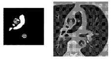
- FIG. 1Aillustrates an example of a scan upon which two regions of interest corresponding to the trunk of the pulmonary artery (P) and the aorta (A) have been hand drawn.
- FIG. 1Billustrates a representative example of the time enhancement curves that are calculated from a transit, timing or test bolus performed as part of a cardiac Computed Tomography Angiogram or CTA procedure for the two regions of interest.
- Accurate and consistent placement of regions of interest in the pulmonary artery and the aorta (and/or other region(s) of interest)is important to achieve desirable results. Accurate and consistent placement of the regions of interest is especially important if the time enhancement curves are to be used for optimization of a diagnostic protocol to be used in an imaging scan. Determining the size, shape, and location of the regions of interest is challenging and requires valuable operator time (for example, to go to a separate evaluation screen, to load the images, to draw the region(s) of interest, and to use the resulting data to generate and/or adjust the contrast/scan protocol).
- tracking test bolus proceduresan operator is required to mark one or more regions of interest prior to contrast being injected. It can be particularly difficult to draw the regions of interest on the image before contrast has been injected. Moreover, factors such as patient movement can result in substantial inaccuracies.
- the present inventionprovides a method of extracting at least one time-value curve to determine a protocol in an imaging procedure using an imaging system, including: determining a first M-dimensional data set of pixel values of a portion of a body of the patient at a first time using the imaging system, wherein M is an integer; determining at least a second M-dimensional data set of pixel values of the portion at a second time using the imaging system; computing a predetermined number of correlated segments of the imaged portion corresponding to a predetermined number of regions of interest of the patient by computing a similarity metric of a time series of pixel values; computing the at least one time-value curve for at least one of the regions of interest; and determining a protocol for a diagnostic scan using the image system based at least in part upon data from the time value curve.
- a vector y x[y x (0) y x (1) . . . y x (T ⁇ 1) y x (T)] can, for example, be determined wherein y is a value of a pixel at location x.
- the segmentscan, for example, be computed using a clustering technique such as K-means clustering.
- K clusterscan, for example, be computed by minimizing the sum of squares of distances between data points and K cluster centroids, wherein K is an integer corresponding to the predetermined number of correlated segments.
- pixel valuesare randomly assigned to one of K clusters and each cluster centroid is a component-wise mean of the pixel values in that cluster after centering and normalizing pixel values to a zero mean and unit standard deviation as follows:
- Each cluster centroidcan, for example, be determined using the following formula:
- y c1 N ⁇ ⁇ x ⁇ cluster ⁇ ⁇ y ⁇ x wherein N is the number of pixels in the cluster.
- the distance from centered and normalized pixel values to each of the K cluster centroids y ccan, for example, be determined using the formula:
- Each centered and normalize pixel valuecan be assigned to the cluster to which it exhibits the minimum computed distance to the centroid.
- the actions of determining each cluster centroid, determining a distance from centered and normalized pixel values to each of the K cluster centroids and assigning/reassigning each centered and normalize pixel value to the cluster to which it exhibits the minimum computed distance to the centroidcan be repeated until convergence, resulting in a segmented image having K segments corresponding to the determined K clusters.
- the methodcan further include filtering the segmented image to eliminate pixels that are not well correlated with neighboring pixels.
- Each pixel of the segmented imagecan, for example, be compared with all eight of its neighboring pixels in filtering.
- the methodcan further include morphologically opening the segmented image.
- the methodcan also include overlaying the segmented image upon a contrast enhanced bolus data set and computing enhancement profiles for each of the K segments.
- the methodcan also further include semantically labeling at least one of the enhancement profiles with a semantic label corresponding to a region of interest of the patient based upon at least one of the characteristics of the labeled enhancement profile as compared to at least one other computed enhancement profiles.
- the present inventionprovides system for extracting at least one time-value curve to determine a protocol in an imaging procedure, including an input system for input of data output from at least one imaging system.
- the dataincludes a first M-dimensional data set of pixel values of a portion of a body of the patient at a first time, wherein M is an integer, and at least a second M-dimensional data set of pixel values of the portion at a second time.
- the systemalso includes at least one processor in communicative connection with the input system and adapted to compute a predetermined number of correlated segments of the imaged portion corresponding to a predetermined number of regions of interest of the patient by computing a similarity metric of a time series of pixel values and computing the at least one time value curve for at least one of the regions of interest.
- the systemalso includes at least one parameter generator system to determine a protocol for a diagnostic scan using the image system based at least in part upon data from the time value curve.
- the systemcan further includes a memory system in communicative connection with the at least one processor.
- the memory systemhas stored therein an algorithm executable by the at least one processor to compute the predetermined number of correlated segments of the imaged portion corresponding to the predetermined number of regions of interest of the patient.
- the systemcan, for example, be in communicative connection with the at least one imaging system.
- the systemcan, for example, be in communicative connection with the at least one injector system.
- At least a portion of the systemis integrated with the at least one imaging system.
- at least a portion of the systemcan be integrated with the at least one injector system.
- FIG. 1Aillustrates operator-drawn regions of interest corresponding to the pulmonary artery and the aorta in a CT image.
- FIG. 1Billustrates time enhancement curves calculated for the operator-determined regions of interest of FIG. 1A .
- FIG. 2illustrates an image that is segmented or labeled (cluster 1 in grey, and cluster 2 in white) after a segmenting procedure of the present invention.
- FIG. 3illustrates the segmented or labeled image after a filtering procedure of the present invention based on similarity to neighboring pixel values.
- FIG. 4illustrates the segmented or labeled image after a morphological opening procedure of the present invention.
- FIG. 5Aillustrates the final, segmented or labeled image overlain on original axial data showing the identified segments or regions of interest (corresponding to the pulmonary artery P and the aorta A).
- FIG. 5Billustrates time enhancement curves calculated for the automatically or system-determined segments or regions of interest of FIG. 5A .
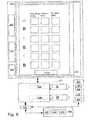
- FIG. 6illustrates one embodiment of a system of the present invention.
- FIG. 7illustrates a concentration/enhancement versus time curve for a transit, timing or test bolus of a contrast medium in the trunk of the pulmonary artery and the ascending aorta.
- FIG. 8illustrates a concentration/enhancement versus time curve in the left heart for a diagnostic injection of contrast medium.
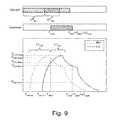
- FIG. 9illustrates an example of relative timing and diagnostic injection protocol phases, scan and enhancement curves for the left heart (LH) and the right heart (RH).
- one or more regions of interestare determined in a portion of a patient's body by the devices, systems and/or methods of the present invention via analysis of a plurality of datasets of values (for example, pixel values) of the portion of the patient's body (in a time series of such datasets) without the requirement that an operator manually draw or otherwise define the regions of interest.
- the dataset of values(for example, point values such as pixel intensity values) need not be displayed to an operator as a viewed image during determination of the one or more regions of interest.
- time value curvesfor example, time enhancement curves in the case that a contrast enhancement medium is injected
- the dataset seriesfor example, a contrast-enhanced transit bolus image series
- the term “pixel”refers to a defined portion or piece (typically, the smallest portion or piece) of data in an M-dimensional dataset of the present invention.
- the M-dimensional datasets of the present inventioncorrespond to two-dimensional datasets corresponding to a two-dimensional digital image wherein each pixel has a pixel value or intensity.
- Three-dimensional imagescan also be used and the term pixel as used herein includes the term “voxel.”
- Multidimensional datasetscan, for example, be created using data from more than one type of imaging system (for example, a combination of data from CT and MRI systems).
- the same CT transit bolus series illustrated in FIG. 1is used as a representative example.
- Time enhancement curves for the pulmonary artery and for the aortaare computed.
- the devices, systems and methods of the present inventioncan be used in connection with generally any region(s) of interest and in connection with generally any imaging methodology (for example, CT, MRI etc.) in which energy is applied to a patient to produce a dataset or image.
- the devises, systems and methods of the present inventioncan be used without the injection of a contrast medium.
- each pixel intensity value of the computed digital imagescorresponds to a single spatial location, given little or no patient motion.
- y x (0)is the baseline enhancement for the pixel
- sis the change in signal due to blood flow
- ⁇is a noise term (assumed in several embodiments of the present invention to be spatially and temporally independent).
- s x (t)For those pixels corresponding to an area through which blood does flow, s x (t) will be well correlated within a region of interest circumscribing a specific territory of the anatomy, (for example, all pixels in the pulmonary trunk will have a similar enhancement pattern).
- the datais first thresholded to exclude obviously non-contrast-enhanced regions (for example, compare the images of FIGS. 1A and 2 ).
- the datasetcan, for example, include all points with at least one non-zero enhancement value in the time series.
- K-means clusteringis an algorithm used to classify, group or segment objects based on attributes thereof into K groups, wherein K is a positive integer number.
- groupingis accomplished by minimizing the sum of squares of distances between data points and a corresponding cluster centroid.
- the distance metric used in the K-means clustering procedurewas one minus the sample correlation between points (treated as sequences of values).
- Each cluster centroidwas the component-wise mean of the points in that cluster, after centering and normalizing those points to, for example, zero mean and unit standard deviation.
- cluster centroidwas computed as follows:
- centroid1 N ⁇ ⁇ x ⁇ cluster ⁇ ⁇ y ⁇ x
- Nis the number of pixels in the cluster.
- the centroidis a T-dimensional, normalized enhancement profile.
- Other potential distance metricscould include Euclidean distance, sum of absolute differences (city-block distance), and the cosine of the two feature vectors.
- a similarity metriccan be thought of as the inverse of a distance metric. The closer two elements are in the selected feature space, the shorter the distance and the greater the similarity.
- Each pixelwas then assigned to the cluster to which it exhibited the minimum computed distance to the centroid.
- cluster assignmentswere (in several embodiments) defined as a state wherein cluster centroids and assignments were stable. For example, convergence can be obtained when the points no longer switch clusters, switch clusters in a stable, oscillating or steady state manner or centroids are no longer changed.
- K-means convergencea labeled or segmented image was generated as illustrated in FIG. 2 wherein a first cluster or cluster 1 is represented by a gray color and a second cluster or cluster 2 is represented by a white color.
- each pixel valuecan be compared to one or more of its neighboring pixel values. In one embodiment, for each pixel, if all eight of its neighbors matched its own label or segment, the pixel kept its label or segment. Otherwise, the pixel was set to zero.
- This filtering process or procedureeliminates pixels on the edges of structures and those that are not correlated with their neighbors. Such filtering of the data of FIG. 2 yielded the image of FIG. 3 .
- a morphological opening(as known in the computer vision and image processing arts) was performed with, for example, a disc-shaped structuring element to eliminate small objects or islands (see FIG. 4 ).
- morphological openingremoves small objects/noise using a structuring element.
- Morphological openingcan be defined as an erosion on an image followed by a dilation on the eroded image, using the same structuring element.
- a structuring elementis superimposed on each of the foreground pixels. If the structuring element is not entirely contained within the foreground, the pixel at that coordinate is removed. Erosion causes foreground regions to shrink, removing isolated areas smaller than the structuring element.
- the structuring elementis superimposed on each of the background pixels. If at least one pixel is contained within the foreground, the pixel at that coordinate is added.
- regions that were not removed during erosionare returned to their original size. Foreground borders are somewhat smoothed, and small islands are removed.
- each clustercan be given a semantic label as illustrated in FIG. 5A .
- the pulmonary arteryis known to peak first, so the cluster with the earlier time to peak was determined to be to the pulmonary artery.
- time-value curves(for example, time-enhancement curves) determined using the computed regions of interest of the present invention are used to facilitate determination of a protocol for an imaging procedure.
- the term “protocol”refer to injection parameters (in the case of injection of a contrast medium) and/or scanner/imaging system parameters for use in a procedure such as a diagnostic imaging scan.
- Injection parametersinclude, for example, flow rate, volume injected, injection duration, contrast agent concentration etc. that define, for example, the timing of, amount of, and/or the nature of fluid(s) to be delivered to a patient during an injection procedure. Such parameters can change over the course of the injection procedure.
- phaserefers generally to a group of parameters that define, for example, the timing of, amount of, and/or the nature of fluid(s) to be delivered to a patient during a period of time (or phase duration) that can be less than the total duration of the injection procedure.
- the parameters of a phaseprovide a description of the injection over a time instance corresponding to the time duration of the phase.
- An injection protocol for a particular injection procedurecan, for example, be described as uniphasic (a single phase), biphasic (two phases) or multiphasic (two or more phases, but typically more than two phases).
- Multiphasic injectionsalso include injections in which the parameters can change continuously over at least a potion of the injection procedure.
- Scanner or imaging system parameters that can be determinedinclude, but are not limited to, the amount of radiation transmitted to the patient, power inputs (for example, voltage or current), timing (for example, scan start time, stop time, delay time and/or duration).
- power inputsfor example, voltage or current
- timingfor example, scan start time, stop time, delay time and/or duration.
- an injection systemsuch as a dual syringe injector system 100 as illustrated in FIG. 6 and as, for example, disclosed in U.S. Pat. No. 6,643,537, Published U.S. Patent Application Publication No. 2004-0064041 and PCT International Patent Application No.
- PCT/US2007/026194for use with the present invention includes two fluid delivery sources (sometimes referred to as source “A” and source “B” herein; such as syringes) that are operable to introduce a first fluid and/or a second fluid (for example, contrast enhancement fluid, saline etc.) to the patient independently (for example, simultaneously, simultaneously in different volumetric flow proportion to each other, or sequentially or subsequent to each other (that is, A then B, or B then A)).
- source Ais in operative connection with a pressurizing mechanism such as a drive member 110 A
- source Bis in operative connection with a pressurizing mechanism such as a drive member 110 B.
- the injection systemincludes a control system 200 in operative connection with injector system 100 that is operable to control the operation of drive members 110 A and 110 B to control injection of fluid A (for example, contrast medium) from source A and injection of fluid B (for example, saline) from source B, respectively.
- Control system 200can, for example, include or be in communicative connection a user interface comprising a display 210 .
- display 210illustrates areas for parameters for injection flow rate, injection volume and injection duration for, for example, three phases of injection or fluid A and/or fluid B.
- the parameters for one or more such phasescan be populated using one or more parameter generation systems and methods based at least in part on data obtained from time enhancement curves for regions of interest determined as described herein.
- Control system 200can include a processor 220 (for example, a digital microprocessor as known in the art) in operative connection with a memory or memory system 230 .
- processor 220for example, a digital microprocessor as known in the art
- fluid delivery systemsincluding multi-patient fluid delivery systems as, for example, disclosed in U.S. Pat. Nos. 7,326,186, 7,094,216, 6,866,654, 6,972,001, 6,699,219, 6,471,674, 6,306,117, 6,149,627, 6,063,052, 5,920,054, 5,843,037, 5,827,219, 5,739,508 and 5,569,181 are also suitable for use in the present invention.
- Imaging system 300can, for example, be a CT system, a Magnetic Resonance Imager (MRI) system, an ultrasound imaging system, or a Positron Emission Tomography (PET) system) or a Single Photon Emission Computed Tomography (SPECT) system as described above.
- the injection systemcan be in communicative connection with imaging system 300 .
- Imaging system 300 and injector system 100can, for example, be in communication connection via input/output ports (represented by terminations of arrows in FIG. 6 ) as known in the art.
- input/output portsrepresented by terminations of arrows in FIG. 6
- imaging system 300 and injector system 100are, for example, illustrated to be in communicative connection via a common communication hub 400 .
- a direct communication linkcan be established.
- Imaging system 300 and injection systems 100can be manually entered using one or more manual input systems (for example, keypads, keyboards mousse etc.) as know in the computer arts.
- Imaging system 300 and injector system or injector 100can also be partially or fully integrated as described, for example, in Published PCT International Patent Application No. WO 2008/011401, the disclosure of which is incorporated herein by reference.
- One, a plurality or all the illustrated components of the injection system and imaging system 300can also or alternatively be integrated with or incorporated within another, separate component that is placed in communicative connection with other system components.
- Software embodying the systems and methods of the present inventioncan, for example, be embodied within one or more separate or standalone systems represented by system 500 which can, for example, include at least one processor (for example, a digital microprocessor), a memory system 520 a display 510 and a manual input system 505 .
- system 500is shown to be in communicative connection with communication hub 400 .
- a direct communication linkcan also be established.
- Further data from one or more systemscan be manually entered into one or more other systems using one or more manual input systems (for example, keypads, mouse etc.) as know in the computer arts.
- Software embodying the systems and methods of the present inventioncan, for example, be stored in memory 530 and executed by processor 520 .
- all or a portion of the functionality of the methods and/or systems of the present inventioncan alternatively reside in an imaging system 300 (which can, for example, include at least one processor 320 , a memory system 330 , a display 310 and a manual input system 305 ) and/or in injector system 100 .
- Data obtained from transit boluses using regions of interest as determined hereincan be used in many ways to, for example, determine imaging procedure protocols.
- at least one parameter for an imaging procedure(which, includes the injection of a contrast enhancement fluid or medium which includes a contrast enhancing agent) is determined via a parameter generation system/methodology as described in, for example, PCT Application No. PCT/US08/67982.
- discrete point data from one or more contrast enhancement curves for one or more regions of interest determined as described hereinis substituted into a model to, for example, determine values for physiological variables in the model.
- the variablescan, for example, be related to cardiopulmonary function.
- variables in a model that is predictive of temporal changes in concentration in a region or regions of interest within a patientare determined or estimated using data from at least one concentration profile for a pharmaceutical (that is, concentration as a function of time) in at least one region of interest.
- a number of discrete data pointsare taken from one or more contrast concentration profiles (that are, for example, provided by time enhancement curves generated using an imaging system) to provide an estimation of the values of such variables.
- contrast concentration profilesthat are, for example, provided by time enhancement curves generated using an imaging system
- such variablesare related to cardiopulmonary function (that is, cardiac, pulmonary and vascular function/dynamics).
- cardiac output (Q CO ) and blood volume (V B )are unknown.
- Two discrete data pointsthat is, two concentrations at two times are used to determine estimates of those variable.
- a time to peak enhancement for first region of interest enhancement T 1 and a time to peak enhancement for the second region of interest enhancement T 2are input into the parameter generation system (algorithms for which can, for example, be embodied in software stored on one or more of memory systems 230 , 330 and 530 ).
- the first region of interestis the pulmonary artery and the second region of interest is the ascending aorta (see, for example, FIG. 7 ).
- Concentration at peak enhancement for the first region of interest enhancement C 1 (T 1 ) and concentration at peak enhancement for the second region of interest enhancement C 2 (T 2 )are also input.
- contrast material injected into each region of interest from a peripheral injection sitecan, for example, be described by the following analytical solution of a physiological model:
- C o ⁇ ( t )⁇ Q inj Q co ⁇ C i ( 1 - e - Q CO V B ⁇ t ) t ⁇ T inj C o ⁇ ( T inj ) ⁇ e - Q CO V B ⁇ ( t - T inj ) t > T inj ( 1 )
- Q inj [ml/s]is the injection flow rate
- T inj [s]is the injection duration
- Q COis the cardiac output [ml/s]
- V Bis the blood volume between the injection site and measurement point [ml]
- C iis the concentration of contrast in a contrast source from which contrast is injected into the patient
- C o (t)is the blood concentration in the region of interest of the agent at time t.
- T injcan, for example, be the amount of time between arrival of contrast enhancement agent and the time to peak enhancement.
- Blood concentration at T injcan be provided by:
- C o ⁇ ( T inj )max ⁇ ⁇ s 2 ⁇ ( T 2 ) K ⁇ C 2 ⁇ ( T 2 ) ( 3 ) wherein max s 2 (T 2 ) [Hu] is the maximum enhancement level in the second region of interest and C 2 (T 2 ) is the concentration at peak enhancement for the second region of interest enhancement.
- Contrast enhancing agent concentration on the first contrast enhancement curve at time T 2can be related to a contrast enhancing agent concentration on the second contrast enhancement curves at time T 2 using the following equation C 1 ( T 2 ) ⁇ C 1 ( T 1 ) ⁇ C 2 ( T 2 ) (4).
- Blood volume V Bcan be determined using one of the following formulas:
- Cardiac output Q COcan be determined using the following formula:
- Q COQ inj C ⁇ ( T 1 ) ⁇ C i ⁇ [ 1 - ( C 1 ⁇ ( T 1 ) - C 2 ⁇ ( T 2 ) C 1 ⁇ ( T 1 ) ) ] T 1 T 2 - T 1 .
- Q COcan be used in the model in which Q CO is a variable to determine the at least one parameter.
- the concentration of contrast agent at peak enhancement C(T Peak ) at the time of peak enhancement T Peak in the second region of interest of an imaging injectioncan be related to the injection flow rate Q inj of the imaging injection and the injection duration T inj of the imaging injection using the formula:
- a concentration of contrast agent in the second region of interest at time of a scan start, C(T start )can be provided by:
- C ⁇ ( T start )Q inj Q CO ⁇ C i [ 1 - e - Q CO V B ⁇ T inj ] 1 - e - Q CO V B ⁇ T inj + e - Q CO V B ⁇ ( T inj - ⁇ ⁇ ⁇ T ) ( 8 ) wherein ⁇ T is the scan duration and wherein C(T start ) is equal to C(T start + ⁇ T) in this embodiment.
- C(T Peak ) and C(T start enhancementscan, for example, be determined for admissible input values for T inj and Q inj wherein a maximum Q inj and a minimum Q inj and a maximum T inj and a minimum T inj can be established.
- Maximum T injcan, for example, be established as a function of scan duration plus a constant, and minimum T inj can, for example, be established as the scan duration.
- the values for the diagnostic protocol flow rate Q* inj and injection duration T* injcan, for example, be determined which are the arguments that minimize the cost function (wherein “Desired” values are provided/input by, for example, an operator):
- the injectioncan be truncated if (T inj +T arrRH )>scanEnd.
- a duration of a dual flow phase wherein both contrast medium and a diluent are injectedcan also be determined.
- a ratio of contrast medium to diluentcan be established for the dual flow phase.
- the end time of the dual flow phasecan, for example be established to be equal to T inj .
- a protocol generation methodology as described abovecan, for example, be used to minimize the dose of contrast a subject receives by considering that subject's cardiac dynamics, drug properties and scan properties.
- the scanbegins at T start , on an unknown point on the upslope of the left heart concentration curve.
- the scanends ⁇ T seconds later (where ⁇ T is the specified scan duration) on the downslope of the curve.
- those two valuesreferred to as C LH-Start on the upslope and C LH-End on the downslope
- C LH-Start on the upslope and C LH-End on the downslopeshould be as close to C LH-Target as possible.
- the right heart curvehas similar associated parameters. However, because C RH-Peak should not occur during the scan window (as too much enhancement in the right heart could lead to streaking or beam hardening artifacts), it was not included as a term in the cost function set forth in Equation (9).
- parametersare added in the optimization procedure related to the dilution phase.
- the dilution ratio (R 2 ) and the duration of the dilution phase ( ⁇ T inj2 )can be added to the optimization procedure.
- the dilution ratiois thereby personalized (instead of using a fixed or set ratio of, for example, 40/60).
- Enhancement targetsare also added to the optimization procedure (for example, cost function) for a second region of interest (the right heart or RH in the representative examples herein) in this embodiment.
- FIG. 9illustrates an example of relative timing and diagnostic injection protocol phases, scan and enhancement curves for the right heart/pulmonary artery and left heart/aorta.
- ⁇was set to equal 1 in several embodiments, which was shown to be a reasonable trade-off between losing consistency with the test bolus flow rate and not reaching target enhancement levels.
- ⁇was set to equal 1000, which puts a very large penalty on exceeding the loaded contrast volume. In that regard, if (Q inj (R 1 ⁇ T inj1 +R 2 ⁇ T inj2 )>V Load ) was true, ⁇ was set to equal 1000. Otherwise, ⁇ was set to equal 0.
- T start * , Q inj * , R 1 * , ⁇ ⁇ ⁇ T inj ⁇ ⁇ 1 * , R 2 * , ⁇ ⁇ ⁇ T inj ⁇ ⁇ 2 *arg ⁇ min T start , Q inj , R 1 , ⁇ ⁇ ⁇ T inj ⁇ ⁇ 1 , R 2 , ⁇ ⁇ ⁇ T inj ⁇ ⁇ 2 ⁇ ( ⁇ C LH ⁇ - ⁇ Peak - C LH ⁇ - ⁇ Peak ⁇ - ⁇ Desired ⁇ + ⁇ C LH ⁇ - ⁇ Start - C LH ⁇ - ⁇ Target ⁇ - ⁇ Desired ⁇ + ⁇ C LH ⁇ - ⁇ End - C LH ⁇ - ⁇ Target ⁇ - ⁇ Desired ⁇ + ⁇
- T arris either T RH-arr or T LH-arr , depending on which curve is being used.
- phase 2when (T arr + ⁇ T inj1 ) ⁇ T ⁇ (T arr + ⁇ T inj1 + ⁇ T inj2 ), the expression is:
Landscapes
- Engineering & Computer Science (AREA)
- Physics & Mathematics (AREA)
- Theoretical Computer Science (AREA)
- Computer Vision & Pattern Recognition (AREA)
- General Physics & Mathematics (AREA)
- Software Systems (AREA)
- General Health & Medical Sciences (AREA)
- Medical Informatics (AREA)
- Probability & Statistics with Applications (AREA)
- Health & Medical Sciences (AREA)
- Data Mining & Analysis (AREA)
- Nuclear Medicine, Radiotherapy & Molecular Imaging (AREA)
- Artificial Intelligence (AREA)
- Quality & Reliability (AREA)
- Radiology & Medical Imaging (AREA)
- Evolutionary Computation (AREA)
- Multimedia (AREA)
- Bioinformatics & Cheminformatics (AREA)
- Bioinformatics & Computational Biology (AREA)
- Evolutionary Biology (AREA)
- General Engineering & Computer Science (AREA)
- Life Sciences & Earth Sciences (AREA)
- Databases & Information Systems (AREA)
- Computing Systems (AREA)
- Apparatus For Radiation Diagnosis (AREA)
- Magnetic Resonance Imaging Apparatus (AREA)
- Image Processing (AREA)
Abstract
Description
wherein the mean
wherein N is the number of pixels in the cluster.
yx=[yx(0)yx(1) . . .yx(T−1)yx(T)]
yx(t)=yx(0)+sx(t)+ηx(t)
where yx(0) is the baseline enhancement for the pixel, s is the change in signal due to blood flow, and η is a noise term (assumed in several embodiments of the present invention to be spatially and temporally independent). In contrast-enhanced imaging, s is related to the amount of contrast in the blood, and that value changes depending on location in space and time. For those pixels corresponding to an area through where blood does not flow, sx(t)=0, and the only enhancement differences will be uncorrelated noise. For those pixels corresponding to an area through which blood does flow, sx(t) will be well correlated within a region of interest circumscribing a specific territory of the anatomy, (for example, all pixels in the pulmonary trunk will have a similar enhancement pattern).
where N is the number of pixels in the cluster. The centroid is a T-dimensional, normalized enhancement profile.
Low computed distances correspond to high correlations, while high computed distances correspond to low correlations. Other potential distance metrics could include Euclidean distance, sum of absolute differences (city-block distance), and the cosine of the two feature vectors. Generally, a similarity metric can be thought of as the inverse of a distance metric. The closer two elements are in the selected feature space, the shorter the distance and the greater the similarity.
wherein the origin, t=0, corresponds to the time at which contrast arrives in the region of interest, Qinj[ml/s] is the injection flow rate, Tinj[s] is the injection duration, QCOis the cardiac output [ml/s], VBis the blood volume between the injection site and measurement point [ml], Ciis the concentration of contrast in a contrast source from which contrast is injected into the patient, and Co(t) is the blood concentration in the region of interest of the agent at time t.
CO(t)=s(t)/K (2)
wherein s(t) [Hounsfield units or HU] is enhancement level at time t and K [mgI/ml] is a conversion factor.
wherein max s2(T2) [Hu] is the maximum enhancement level in the second region of interest and C2(T2) is the concentration at peak enhancement for the second region of interest enhancement.
C1(T2)≈C1(T1)−C2(T2) (4).
QCOcan be used in the model in which QCOis a variable to determine the at least one parameter.
wherein ΔT is the scan duration and wherein C(Tstart) is equal to C(Tstart+ΔT) in this embodiment.
Voltot=Qinj·Tinj.
scanDelay=T2−(TinjTB+arrOffset)+Tstart (10)
wherein TinjTBis the injection duration of the timing bolus and arrOffset is an arrival time offset value; and a scan end time can be determined by adding the scan delay to the scan duration.
TarrRH=T1−(TinjTB+arrOffset) (11)
wherein T1Peakis the time to peak enhancement in the first region of interest.
Tinj=scanEnd−TarrRH. (12)
Depending on the dilution ratios, the peak value for the LH occurs during the upslope (phase 1) or dilution phase (phase 2), and is therefore the greater of the two:
For the remaining concentration values, given an absolute time T (either the start or end of the scan), the RH and LH curves can each be in one of 3 regions—upslope (phase 1), dilution (phase 2), or decay (phase 3). When T<(Tarr+ΔTinj1), the expression is:
Note that Tarris either TRH-arror TLH-arr, depending on which curve is being used. For the dilution phase (phase 2), when (Tarr+ΔTinj1)<T<(Tarr+ΔTinj1+ΔTinj2), the expression is:
Finally, in the decay phase (phase 3), when T>(Tarr+ΔTinjA+ΔTinjAB), the expression is:
Claims (23)
y=[yx(0)yx(1) . . .yx(T−1)yx(T)],
yx(t)=yx(0)+sx(t)+ηx(t),
yx=[yx(0)yx(1) . . .yx(T−1)yx(T)],
yx(t)=yx(0)+sx(t)+ηx(t),
Priority Applications (7)
| Application Number | Priority Date | Filing Date | Title |
|---|---|---|---|
| US12/144,811US8315449B2 (en) | 2008-06-24 | 2008-06-24 | Identification of regions of interest and extraction of time value curves in imaging procedures |
| CN200980123987.3ACN102077264B (en) | 2008-06-24 | 2009-06-12 | Identification of regions of interest and extraction of time value curves in imaging procedures |
| EP09770746.7AEP2297722B1 (en) | 2008-06-24 | 2009-06-12 | Identification of regions of interest and extraction of time value curves in imaging procedures |
| PCT/US2009/047168WO2009158212A1 (en) | 2008-06-24 | 2009-06-12 | Identification of regions of interest and extraction of time value curves in imaging procedures |
| JP2011516429AJP5555695B2 (en) | 2008-06-24 | 2009-06-12 | Identification of target area and extraction of time value curve in imaging method |
| US13/655,525US8699770B2 (en) | 2008-06-24 | 2012-10-19 | Identification of regions of interest and extraction of time value curves in imaging procedures |
| JP2014113856AJP5851553B2 (en) | 2008-06-24 | 2014-06-02 | Identification of target area and extraction of time value curve in imaging method |
Applications Claiming Priority (1)
| Application Number | Priority Date | Filing Date | Title |
|---|---|---|---|
| US12/144,811US8315449B2 (en) | 2008-06-24 | 2008-06-24 | Identification of regions of interest and extraction of time value curves in imaging procedures |
Related Child Applications (1)
| Application Number | Title | Priority Date | Filing Date |
|---|---|---|---|
| US13/655,525DivisionUS8699770B2 (en) | 2008-06-24 | 2012-10-19 | Identification of regions of interest and extraction of time value curves in imaging procedures |
Publications (2)
| Publication Number | Publication Date |
|---|---|
| US20090316970A1 US20090316970A1 (en) | 2009-12-24 |
| US8315449B2true US8315449B2 (en) | 2012-11-20 |
Family
ID=41431355
Family Applications (2)
| Application Number | Title | Priority Date | Filing Date |
|---|---|---|---|
| US12/144,811Expired - Fee RelatedUS8315449B2 (en) | 2008-06-24 | 2008-06-24 | Identification of regions of interest and extraction of time value curves in imaging procedures |
| US13/655,525ActiveUS8699770B2 (en) | 2008-06-24 | 2012-10-19 | Identification of regions of interest and extraction of time value curves in imaging procedures |
Family Applications After (1)
| Application Number | Title | Priority Date | Filing Date |
|---|---|---|---|
| US13/655,525ActiveUS8699770B2 (en) | 2008-06-24 | 2012-10-19 | Identification of regions of interest and extraction of time value curves in imaging procedures |
Country Status (5)
| Country | Link |
|---|---|
| US (2) | US8315449B2 (en) |
| EP (1) | EP2297722B1 (en) |
| JP (2) | JP5555695B2 (en) |
| CN (1) | CN102077264B (en) |
| WO (1) | WO2009158212A1 (en) |
Cited By (6)
| Publication number | Priority date | Publication date | Assignee | Title |
|---|---|---|---|---|
| US20160073997A1 (en)* | 2013-06-11 | 2016-03-17 | Kabushiki Kaisha Toshiba | X ray computed tomography apparatus and scan start timing determination method |
| US20160140712A1 (en)* | 2013-05-13 | 2016-05-19 | Kabushiki Kaisha Toshiba | Medical image analyzer |
| US9949704B2 (en) | 2012-05-14 | 2018-04-24 | Bayer Healthcare Llc | Systems and methods for determination of pharmaceutical fluid injection protocols based on x-ray tube voltage |
| US10166326B2 (en) | 2004-11-24 | 2019-01-01 | Bayer Healthcare Llc | Devices, systems and methods for determining parameters of one or more phases of an injection procedure |
| US10383590B2 (en)* | 2015-09-28 | 2019-08-20 | General Electric Company | Methods and systems for adaptive scan control |
| US20210264188A1 (en)* | 2020-02-26 | 2021-08-26 | Hitachi, Ltd. | Image prediction system |
Families Citing this family (24)
| Publication number | Priority date | Publication date | Assignee | Title |
|---|---|---|---|---|
| EP1812101A4 (en) | 2004-11-16 | 2014-04-23 | Medrad Inc | Modeling of pharmaceutical propagation |
| WO2011058459A1 (en)* | 2009-11-16 | 2011-05-19 | Koninklijke Philips Electronics, N.V. | Functional imaging |
| RU2559930C2 (en)* | 2010-02-02 | 2015-08-20 | Конинклейке Филипс Электроникс Н.В. | Formation of functional images |
| AU2011270772C1 (en) | 2010-06-24 | 2017-04-20 | Bayer Healthcare Llc | Modeling of pharmaceutical propagation and parameter generation for injection protocols |
| JP5750381B2 (en)* | 2012-02-13 | 2015-07-22 | 株式会社日立製作所 | Region extraction processing system |
| US9949696B2 (en)* | 2013-03-14 | 2018-04-24 | Tensys Medical, Inc. | Apparatus and methods for computing cardiac output of a living subject via applanation tonometry |
| CN105022719B (en) | 2014-04-23 | 2019-06-28 | Ge医疗系统环球技术有限公司 | Medicine angiography system and method |
| EP3093678A1 (en) | 2015-05-13 | 2016-11-16 | Bayer Pharma Aktiengesellschaft | Method for optimizing prediction of bolus arrival time using mri for diagnostic imaging |
| KR102148662B1 (en)* | 2015-08-07 | 2020-08-31 | 상하이 유나이티드 이미징 헬쓰케어 컴퍼니, 리미티드. | Multi-mode imaging system and method |
| JP6571472B2 (en)* | 2015-09-28 | 2019-09-04 | ザイオソフト株式会社 | Medical image processing apparatus, medical image imaging apparatus, medical image processing method, medical image imaging method, and medical image processing program |
| US11298072B2 (en) | 2016-07-01 | 2022-04-12 | Bostel Technologies, Llc | Dermoscopy diagnosis of cancerous lesions utilizing dual deep learning algorithms via visual and audio (sonification) outputs |
| US11484247B2 (en)* | 2016-07-01 | 2022-11-01 | Bostel Technologies, Llc | Phonodermoscopy, a medical device system and method for skin diagnosis |
| US10026014B2 (en)* | 2016-10-26 | 2018-07-17 | Nxp Usa, Inc. | Method and apparatus for data set classification based on generator features |
| US10297038B2 (en)* | 2017-03-30 | 2019-05-21 | Siemens Healthcare Gmbh | Determination and presentation of flow transit curves |
| JP7343399B2 (en) | 2017-06-16 | 2023-09-12 | バイエル・ヘルスケア・エルエルシー | Systems and methods for generation of split bolus protocols |
| CN108197567B (en)* | 2017-12-29 | 2021-08-24 | 百度在线网络技术(北京)有限公司 | Method, apparatus and computer readable medium for image processing |
| CN110547821B (en)* | 2018-05-31 | 2024-04-26 | 通用电气公司 | CT system, method and related computer readable medium for tracking target intervention |
| US11341636B2 (en)* | 2019-11-01 | 2022-05-24 | GE Precision Healthcare LLC | Methods and systems for an adaptive five-zone perfusion scan |
| CN111127485B (en)* | 2019-12-25 | 2023-07-14 | 东软集团股份有限公司 | Method, device and equipment for extracting target area in CT image |
| CN111568459B (en)* | 2020-06-03 | 2021-07-13 | 江苏省中医院 | Method for determining CT pulmonary artery imaging scanning delay time |
| KR102671246B1 (en)* | 2020-09-18 | 2024-06-03 | 세메스 주식회사 | Apparatus for treating substrate and method of determining whether substrate processing is normal |
| US11995831B2 (en) | 2021-04-09 | 2024-05-28 | Wisconsin Alumni Research Foundation | Method and apparatus for optimizing the use of contrast agents during medical imaging |
| JP7728687B2 (en)* | 2021-10-29 | 2025-08-25 | キヤノンメディカルシステムズ株式会社 | Medical image processing device, medical image processing method, and program |
| WO2024083466A1 (en)* | 2022-10-17 | 2024-04-25 | Bayer Aktiengesellschaft | Automated analysis of radiological images |
Citations (131)
| Publication number | Priority date | Publication date | Assignee | Title |
|---|---|---|---|---|
| US3701345A (en) | 1970-09-29 | 1972-10-31 | Medrad Inc | Angiographic injector equipment |
| US3812843A (en) | 1973-03-12 | 1974-05-28 | Lear Siegler Inc | Method and apparatus for injecting contrast media into the vascular system |
| US3888239A (en) | 1974-06-21 | 1975-06-10 | Morton K Rubinstein | Fluid injection system |
| US3898983A (en) | 1973-10-03 | 1975-08-12 | James O Elam | Device and method for detecting the degree of muscle relaxation of a medical patient |
| US4135247A (en) | 1977-08-15 | 1979-01-16 | Siemens Aktiengesellschaft | Tomography signal processing system |
| US4151845A (en) | 1977-11-25 | 1979-05-01 | Miles Laboratories, Inc. | Blood glucose control apparatus |
| US4207871A (en) | 1978-06-07 | 1980-06-17 | Imed Corporation | System for controlling the flow of intravenous fluids to a patient |
| US4280494A (en) | 1979-06-26 | 1981-07-28 | Cosgrove Robert J Jun | System for automatic feedback-controlled administration of drugs |
| US4319568A (en) | 1979-10-29 | 1982-03-16 | Vickers Limited | Liquid dispensing apparatus |
| US4340153A (en) | 1980-11-28 | 1982-07-20 | Spivey David L | Method and apparatus for medication dispensing |
| US4392849A (en) | 1981-07-27 | 1983-07-12 | The Cleveland Clinic Foundation | Infusion pump controller |
| US4396385A (en) | 1980-12-05 | 1983-08-02 | Baxter Travenol Laboratories, Inc. | Flow metering apparatus for a fluid infusion system |
| US4409966A (en) | 1981-05-29 | 1983-10-18 | Lambrecht Richard M | Method and apparatus for injecting a substance into the bloodstream of a subject |
| US4444198A (en) | 1981-12-21 | 1984-04-24 | Petre John H | Circulatory monitoring system and method |
| US4477923A (en) | 1982-02-03 | 1984-10-16 | Siemens Aktiengesellschaft | X-ray diagnostic system for angiographic radiographs |
| US4479761A (en) | 1982-12-28 | 1984-10-30 | Baxter Travenol Laboratories, Inc. | Actuator apparatus for a prepackaged fluid processing module having pump and valve elements operable in response to externally applied pressures |
| WO1985000292A1 (en) | 1983-07-11 | 1985-01-31 | Imperial Chemical Industries Plc | Fluid delivery apparatus |
| US4544949A (en) | 1982-03-05 | 1985-10-01 | Tokyo Shibaura Denki Kabushiki Kaisha | X-Ray diagnostic apparatus and method |
| US4551133A (en) | 1984-04-16 | 1985-11-05 | American Hospital Supply Corporation | Patient controlled medication infusion system |
| US4585009A (en) | 1983-02-28 | 1986-04-29 | E. R. Squibb & Sons, Inc. | Strontium-rubidium infusion pump with in-line dosimetry |
| US4611340A (en) | 1983-05-20 | 1986-09-09 | Kabushiki Kaisha Toshiba | Apparatus for examining a biological object by using radiation |
| US4633307A (en) | 1984-09-13 | 1986-12-30 | Kabushiki Kaisha Toshiba | Digital subtraction fluorographic method and apparatus |
| US4634426A (en) | 1984-12-11 | 1987-01-06 | Baxter Travenol Laboratories | Medical infusion controller and user interface |
| US4636144A (en) | 1982-07-06 | 1987-01-13 | Fujisawa Pharmaceutical Co., Ltd. | Micro-feed pump for an artificial pancreas |
| US4710166A (en) | 1985-11-08 | 1987-12-01 | Quest Medical, Inc. | Automated drug additive infusion system |
| US4723261A (en) | 1983-12-22 | 1988-02-02 | U.S. Philips Corporation | X-ray examination apparatus incorporating image subtraction |
| WO1988003815A1 (en) | 1985-06-04 | 1988-06-02 | Baxter Deutschland Gmbh | Multi-path valve for a device for producing or administering infusion solutions |
| US4798590A (en) | 1983-11-22 | 1989-01-17 | Medical Technology Products, Inc. | Intravenous infusion pumping system including independent pump set |
| US4838856A (en) | 1987-07-02 | 1989-06-13 | Truckee Meadows Research & Development | Fluid infusion flow control system |
| US4853521A (en) | 1987-12-28 | 1989-08-01 | Claeys Ronald W | System for verifying and recording drug administration to a patient |
| US4854324A (en) | 1984-01-31 | 1989-08-08 | Medrad, Inc. | Processor-controlled angiographic injector device |
| US4874359A (en) | 1987-12-14 | 1989-10-17 | White Frederick R | Power infuser |
| US4880014A (en) | 1987-08-14 | 1989-11-14 | Zarowitz Barbara J | Method for determining therapeutic drug dosage using bioelectrical resistance and reactance measurements |
| US4903705A (en) | 1984-11-09 | 1990-02-27 | Hitachi Medical Corporation | Digital radiography apparatus |
| US4913154A (en) | 1987-11-19 | 1990-04-03 | Siemens Aktiengesellschaft | Medical examination installation with improved image contrast |
| US4925444A (en) | 1987-08-07 | 1990-05-15 | Baxter Travenol Laboratories, Inc. | Closed multi-fluid delivery system and method |
| US4943279A (en) | 1988-09-30 | 1990-07-24 | C. R. Bard, Inc. | Medical pump with infusion controlled by a detachable coded label |
| US4966579A (en) | 1988-05-21 | 1990-10-30 | Fresenius Ag | Apparatus for dosed continuous simultaneous infusion of a plurality of infusion solutions or medicaments |
| US5018173A (en) | 1988-10-18 | 1991-05-21 | Kabushiki Kaisha Toshiba | Diagnosis apparatus using X-ray CT device |
| US5034987A (en) | 1988-12-09 | 1991-07-23 | Nippon Identograph Co., Ltd. | Continuous photographing and observing of a three-dimensional image |
| US5040537A (en) | 1987-11-24 | 1991-08-20 | Hitachi, Ltd. | Method and apparatus for the measurement and medical treatment using an ultrasonic wave |
| US5078683A (en) | 1990-05-04 | 1992-01-07 | Block Medical, Inc. | Programmable infusion system |
| CA2045070A1 (en) | 1990-07-31 | 1992-02-01 | Kazuaki Mizoguchi | Control system for dsa and ptca |
| US5088981A (en) | 1985-01-18 | 1992-02-18 | Howson David C | Safety enhanced device and method for effecting application of a therapeutic agent |
| US5104374A (en) | 1990-01-16 | 1992-04-14 | Bishko Jay R | Electronic fluid flow rate controller for controlling the infusion of intravenous drugs into a patient |
| US5111492A (en) | 1990-07-06 | 1992-05-05 | General Electric Cgr S.A. | X-ray diagnosis system for angiographic examination with device for the automatic tracking of a contrast medium |
| US5128121A (en) | 1988-04-08 | 1992-07-07 | Nycomed As | Mixture of a positive and negative contrast agent for magnetic resonance imaging |
| US5135000A (en) | 1990-09-19 | 1992-08-04 | Raizot University Authority For Applied Research & Industrial Development Ltd. | Method of measuring regional tissue blood flow |
| US5180896A (en) | 1990-10-11 | 1993-01-19 | University Of Florida | System and method for in-line heating of medical fluid |
| US5300031A (en) | 1991-06-07 | 1994-04-05 | Liebel-Flarsheim Company | Apparatus for injecting fluid into animals and disposable front loadable syringe therefor |
| US5301672A (en) | 1991-12-09 | 1994-04-12 | Siemens Aktiengesellschaft | Radiological diagnostics system employing a contrast agent |
| US5317506A (en) | 1989-01-30 | 1994-05-31 | Abbott Laboratories | Infusion fluid management system |
| WO1994015664A1 (en) | 1993-01-07 | 1994-07-21 | Man Fai Shiu | Manifold |
| US5339799A (en) | 1991-04-23 | 1994-08-23 | Olympus Optical Co., Ltd. | Medical system for reproducing a state of contact of the treatment section in the operation unit |
| US5349625A (en) | 1992-03-27 | 1994-09-20 | Siemens Aktiengesellschaft | X-ray diagnostics installation for peripheral angiography examinations |
| EP0619122A1 (en) | 1993-04-08 | 1994-10-12 | Getz Bros. Co.,Ltd. | Syringe control system for DSA and PTCA |
| US5361761A (en) | 1992-06-17 | 1994-11-08 | Wisconsin Alumni Research Foundation | Method and apparatus for measuring blood iodine concentration |
| US5368567A (en) | 1992-07-27 | 1994-11-29 | Schneider (Usa) Inc. | Dilatation balloon catheter with infusion lumen |
| US5368562A (en) | 1993-07-30 | 1994-11-29 | Pharmacia Deltec, Inc. | Systems and methods for operating ambulatory medical devices such as drug delivery devices |
| US5382232A (en) | 1992-03-13 | 1995-01-17 | Ivac Corporation | Infusion system with air-in-line clear function |
| US5383858A (en) | 1992-08-17 | 1995-01-24 | Medrad, Inc. | Front-loading medical injector and syringe for use therewith |
| US5385540A (en) | 1993-05-26 | 1995-01-31 | Quest Medical, Inc. | Cardioplegia delivery system |
| US5417213A (en) | 1993-06-07 | 1995-05-23 | Prince; Martin R. | Magnetic resonance arteriography with dynamic intravenous contrast agents |
| US5445621A (en) | 1991-12-20 | 1995-08-29 | Abbott Laboratories | Drug identification and security apparatus for infusion and pumping systems |
| US5456255A (en) | 1993-07-12 | 1995-10-10 | Kabushiki Kaisha Toshiba | Ultrasonic diagnosis apparatus |
| US5458128A (en) | 1994-06-17 | 1995-10-17 | Polanyi; Michael | Method and apparatus for noninvasively measuring concentration of a dye in arterial blood |
| US5459769A (en) | 1994-11-09 | 1995-10-17 | General Electric Company | Procedure for monitoring contrast agent application in a CT imaging system |
| US5469849A (en) | 1993-06-14 | 1995-11-28 | Kabushiki Kaisha Toshiba | Ultrasound diagnosis apparatus |
| US5472403A (en) | 1993-05-11 | 1995-12-05 | The Regents Of The University Of California | Device for automatic injection of radionuclide |
| US5485831A (en) | 1992-11-30 | 1996-01-23 | University Hospital (London) Development Corporation | Pulse-injector for quantitative angiographic blood-flow measurements |
| US5494822A (en) | 1992-09-21 | 1996-02-27 | Bio-Preserve Medical Corporation | Organ perfusion device |
| US5494036A (en) | 1993-11-26 | 1996-02-27 | Medrad, Inc. | Patient infusion system for use with MRI |
| US5496273A (en) | 1991-12-20 | 1996-03-05 | Abbott Laboratories | Automated drug infusion system with autopriming |
| US5507412A (en) | 1993-06-19 | 1996-04-16 | Dragerwerk Ag | Centralized multichannel fluid delivery system |
| US5522798A (en) | 1994-10-17 | 1996-06-04 | Abbott Laboratories | Control of a multi-channel drug infusion pump using a pharmacokinetic model |
| US5531679A (en) | 1994-03-14 | 1996-07-02 | Schulman; Joseph H. | Fluidic infusion system for catheter or probe |
| US5569181A (en) | 1993-10-28 | 1996-10-29 | Medrad, Inc. | Sterility assurance for contrast delivery system |
| US5573515A (en) | 1995-04-20 | 1996-11-12 | Invasatec, Inc. | Self purging angiographic injector |
| US5583902A (en) | 1995-10-06 | 1996-12-10 | Bhb General Partnership | Method of and apparatus for predicting computed tomography contrast enhancement |
| US5687208A (en) | 1995-10-06 | 1997-11-11 | Bhb General Partnership | Method of and apparatus for predicting computed tomography contrast enhancement with feedback |
| US5713358A (en) | 1996-03-26 | 1998-02-03 | Wisconsin Alumni Research Foundation | Method for producing a time-resolved series of 3D magnetic resonance angiograms during the first passage of contrast agent |
| US5724976A (en) | 1994-12-28 | 1998-03-10 | Kabushiki Kaisha Toshiba | Ultrasound imaging preferable to ultrasound contrast echography |
| US5739508A (en) | 1994-07-12 | 1998-04-14 | Medrad, Inc. | Closed loop information path for medical fluid delivery systems |
| US5743266A (en) | 1995-04-25 | 1998-04-28 | Molecular Biosystems, Inc. | Method for processing real-time contrast enhanced ultrasonic images |
| WO1998020919A1 (en) | 1996-11-08 | 1998-05-22 | Schering Ag | Device to obtain constant density of contrast agents in tissues and organs |
| US5768405A (en) | 1993-07-22 | 1998-06-16 | U.S Philips Corporation | Digital image processing method for local determination of the center and the width of objects in the form of contrasting bands on a background |
| US5796862A (en) | 1996-08-16 | 1998-08-18 | Eastman Kodak Company | Apparatus and method for identification of tissue regions in digital mammographic images |
| US5827219A (en) | 1993-10-28 | 1998-10-27 | Medrad, Inc. | Injection system and pumping system for use therein |
| US5840026A (en) | 1994-09-21 | 1998-11-24 | Medrad, Inc. | Patient specific dosing contrast delivery systems and methods |
| US5843037A (en) | 1993-10-28 | 1998-12-01 | Medrad Inc. | Multipatient fluid dispensing |
| US5865744A (en) | 1996-09-16 | 1999-02-02 | Lemelson; Jerome H. | Method and system for delivering therapeutic agents |
| US5881124A (en) | 1994-03-31 | 1999-03-09 | Arch Development Corporation | Automated method and system for the detection of lesions in medical computed tomographic scans |
| US5902054A (en) | 1996-01-31 | 1999-05-11 | Canon Kabushiki Kaisha | Energy saving image edging method and device |
| US6055985A (en) | 1999-04-09 | 2000-05-02 | B.H.B., L.C. | Methods for injecting a contrast medium to generate prolonged uniform vascular enhancement |
| US6073042A (en) | 1997-09-25 | 2000-06-06 | Siemens Medical Systems, Inc. | Display of three-dimensional MRA images in which arteries can be distinguished from veins |
| WO2000061216A1 (en) | 1999-04-09 | 2000-10-19 | B.H.B., L.C. | Contrast injector for injecting a contrast medium to generate prolonged uniform vascular enhancement |
| US6201889B1 (en) | 1996-04-24 | 2001-03-13 | Shriners Hospital For Children | Apparatus and computer program for generating a feedback code |
| US6236706B1 (en) | 1996-12-12 | 2001-05-22 | General Electric Company | Methods and apparatus for predicting contrast agent uptake in a computed tomography system |
| US6317623B1 (en) | 1999-03-12 | 2001-11-13 | Medrad, Inc. | Apparatus and method for controlling contrast enhanced imaging procedures |
| US6344030B1 (en) | 1995-04-20 | 2002-02-05 | Acist Medical Systems, Inc. | Random speed change injector |
| US6381486B1 (en)* | 1999-01-08 | 2002-04-30 | Wisconsin Alumni Research Foundation | Magnetic resonance angiography with vessel segmentation |
| US6397097B1 (en) | 1998-03-16 | 2002-05-28 | Siemens Aktiengesellschaft | Method and control apparatus for tracking a contrast agent in an examination subject using a medical imaging device |
| US6397098B1 (en) | 1994-09-21 | 2002-05-28 | Medrad, Inc. | Data communication and control for medical imaging systems |
| US6402697B1 (en) | 1999-01-21 | 2002-06-11 | Metasensors, Inc. | Non-invasive cardiac output and pulmonary function monitoring using respired gas analysis techniques and physiological modeling |
| US6471674B1 (en) | 2000-04-21 | 2002-10-29 | Medrad, Inc. | Fluid delivery systems, injector systems and methods of fluid delivery |
| US6478735B1 (en) | 1999-01-28 | 2002-11-12 | The United States Of America As Represented By The Administrator Of The National Aeronautics And Space Administration | Physiological feedback method and system |
| US6556695B1 (en) | 1999-02-05 | 2003-04-29 | Mayo Foundation For Medical Education And Research | Method for producing high resolution real-time images, of structure and function during medical procedures |
| US6597938B2 (en) | 2001-08-16 | 2003-07-22 | Koninklijke Philips Electronics, N.V. | System for assistance of parameter determination and diagnosis in MRI dynamic uptake studies |
| US6626862B1 (en) | 2000-04-04 | 2003-09-30 | Acist Medical Systems, Inc. | Fluid management and component detection system |
| US6643537B1 (en) | 1999-07-30 | 2003-11-04 | Medrad, Inc. | Programmable injector control |
| US6652489B2 (en) | 2000-02-07 | 2003-11-25 | Medrad, Inc. | Front-loading medical injector and syringes, syringe interfaces, syringe adapters and syringe plungers for use therewith |
| US6656157B1 (en) | 1995-04-20 | 2003-12-02 | Acist Medical Systems, Inc. | Infinitely refillable syringe |
| US6673033B1 (en) | 1999-11-24 | 2004-01-06 | Medrad, Inc. | Injectors, injector systems and injector control |
| US20040015078A1 (en) | 1993-10-28 | 2004-01-22 | Evans Russell Morrison | Total system for contrast delivery |
| WO2004012787A2 (en) | 2002-08-02 | 2004-02-12 | Liebel-Flarsheim Company | Injector |
| US20040025452A1 (en) | 2002-08-12 | 2004-02-12 | Mclean Frederick Bruce | Baluster retaining member |
| US20040064040A1 (en) | 2002-09-26 | 2004-04-01 | Kazumasa Masuda | Liquid injector for injecting contrast medium at variable rate into a subject who is to be imaged by imaging diagnostic apparatus |
| US20040064041A1 (en) | 2002-05-30 | 2004-04-01 | Lazzaro Frank A. | Front-loading medical injector and syringes, syringe interfaces, syringe adapters and syringe plungers for use therewith |
| US6776764B2 (en) | 2002-03-01 | 2004-08-17 | University Of Pittsburgh Of The Commonwealth System Of Higher Education | Use of aortic pulse pressure and flow in bedside hemodynamic management |
| US20040162484A1 (en) | 2003-02-18 | 2004-08-19 | Nemoto Kyorindo Co., Ltd. | Liquid injector with appropriate operating conditions set by selecting displayed image |
| US6866654B2 (en) | 2000-10-18 | 2005-03-15 | Medrad, Inc. | Pressure isolation mechanisms and fluid delivery systems including pressure isolation mechanisms |
| US6866653B2 (en) | 2002-10-31 | 2005-03-15 | Kyongtae T. Bae | Method and apparatus for sequential delivery of multiple injectable substances stored in a prefilled syringe |
| US6876720B2 (en) | 2001-12-20 | 2005-04-05 | Kabushiki Kaisha Toshiba | X-ray computed tomography apparatus |
| US6879853B2 (en) | 1997-10-06 | 2005-04-12 | James F. M. Meaney | Method and apparatus for magnetic resonance arteriography using contrast agents |
| US20070016016A1 (en)* | 2005-05-31 | 2007-01-18 | Gabriel Haras | Interactive user assistant for imaging processes |
| US7267667B2 (en) | 2002-07-11 | 2007-09-11 | Boston Scientific Scimed, Inc. | Fluid management system for coronary intervention |
| US7267666B1 (en) | 1995-04-20 | 2007-09-11 | Acist Medical Systems, Inc. | Angiographic injector system with multiple processor redundancy |
| US7292720B2 (en) | 2002-07-09 | 2007-11-06 | Siemens Aktiengesellschaft | Method and magnetic resonance tomography apparatus for graphic planning of angiographic exposures using a contrast agent |
| US20080101678A1 (en) | 2006-10-25 | 2008-05-01 | Agfa Healthcare Nv | Method for Segmenting Digital Medical Image |
| US7672711B2 (en)* | 2005-09-01 | 2010-03-02 | Siemens Aktiengesellschaft | Method and system for providing tomographic pictures of a patient by using contrast medium injections |
| US7864997B2 (en)* | 2006-04-28 | 2011-01-04 | Pie Medical Imaging B.V. | Method, apparatus and computer program product for automatic segmenting of cardiac chambers |
Family Cites Families (56)
| Publication number | Priority date | Publication date | Assignee | Title |
|---|---|---|---|---|
| US3941126A (en) | 1974-08-08 | 1976-03-02 | Dietrich Joseph W | Apparatus for long term intravenous administration of diluted incompatible multiple medications |
| JPS5226193A (en) | 1975-08-22 | 1977-02-26 | Houseikai | Remote control barium injector |
| US4191183A (en) | 1977-10-31 | 1980-03-04 | Barry Mendelson | Mixing chamber for use in plural medical liquid intravenous administration set |
| US4187057A (en) | 1978-01-11 | 1980-02-05 | Stewart-Naumann Laboratories, Inc. | Peristaltic infusion pump and disposable cassette for use therewith |
| JPS5675131A (en) | 1979-11-22 | 1981-06-22 | Olympus Optical Co | Endoscope apparatus |
| US4447230A (en) | 1981-08-05 | 1984-05-08 | Quest Medical, Inc. | Intravenous administration set assembly |
| US4512764A (en) | 1982-09-27 | 1985-04-23 | Wunsch Richard E | Manifold for controlling administration of multiple intravenous solutions and medications |
| US4655197A (en) | 1982-12-01 | 1987-04-07 | Snyder Laboratories, Inc. | Lavage system with variable frequency, flow rate and pressure |
| US4559036A (en) | 1983-12-14 | 1985-12-17 | Wunsch Richard E | Apparatus for controlling administration of multiple intravenous solutions and medications |
| US4563175A (en) | 1983-12-19 | 1986-01-07 | Lafond Margaret | Multiple syringe pump |
| JPS61220628A (en) | 1985-03-28 | 1986-09-30 | 株式会社 日立メデイコ | X-ray dynamic image measuring apparatus |
| JPH072182B2 (en) | 1986-04-07 | 1995-01-18 | テルモ株式会社 | Infusion pump |
| US4750643A (en) | 1986-08-04 | 1988-06-14 | Sugrin Surgical Instrumentation, Inc. | Sterile fluid dispensing system and method |
| US4754786A (en) | 1986-09-05 | 1988-07-05 | Roderick Roberts | Sterile fluid storage and dispensing apparatus and method for filling same |
| SE457056B (en) | 1987-01-29 | 1988-11-28 | Gambro Ab | SYSTEM FOR PREPARING A SCIENTIFIC INTENDED FOR MEDICAL TREATMENT |
| US4887554A (en) | 1987-05-27 | 1989-12-19 | Whitford Darryl R | Animal drench |
| US4795429A (en) | 1987-10-28 | 1989-01-03 | Feldstein Marvin A | Method and apparatus for use in the control of intravenous medication introduction |
| US4857056A (en) | 1988-07-06 | 1989-08-15 | Sherwood Medical Company | Auto-flush syringe pump |
| US4946439A (en) | 1988-08-15 | 1990-08-07 | Critikon, Inc. | Dual source parenteral infusion system with secondary infusion module |
| GB8822708D0 (en) | 1988-09-28 | 1988-11-02 | Core Consulting Group | Improved microwave-powered heating device |
| US5009654A (en) | 1989-03-10 | 1991-04-23 | Baxter International Inc. | Sterile product and method for sterilizing and assembling such product |
| US5032112A (en) | 1989-11-22 | 1991-07-16 | Baxter International Inc. | Dual source intravenous administration set having an intravenous pump |
| US5400792A (en) | 1990-11-20 | 1995-03-28 | Siemens Aktiengesellschaft | Medical diagnostics installation controllable from a central work station |
| JPH05290317A (en)* | 1992-04-13 | 1993-11-05 | Mitsubishi Electric Corp | Magnetic head and its production |
| US5310997A (en) | 1992-09-10 | 1994-05-10 | Tandy Corporation | Automated order and delivery system |
| US5328463A (en) | 1992-09-18 | 1994-07-12 | Namic U.S.A. Corporation | Contrast media and fluid introduction system |
| US5378231A (en) | 1992-11-25 | 1995-01-03 | Abbott Laboratories | Automated drug infusion system |
| US5474683A (en) | 1993-03-03 | 1995-12-12 | Deka Products Limited Partnership | Peritoneal dialysis systems and methods employing pneumatic pressure and temperature-corrected liquid volume measurements |
| US5515851A (en) | 1993-07-30 | 1996-05-14 | Goldstein; James A. | Angiographic fluid control system |
| US5431627A (en) | 1993-11-12 | 1995-07-11 | Abbott Laboratories | Cassette identification system for use with a multi-program drug infusion pump |
| EP0885616A1 (en)* | 1997-06-20 | 1998-12-23 | Schering Aktiengesellschaft | Use of intravenous contrast agents, and apparatus for projectionsmammography |
| US6554798B1 (en) | 1998-08-18 | 2003-04-29 | Medtronic Minimed, Inc. | External infusion device with remote programming, bolus estimator and/or vibration alarm capabilities |
| US6387098B1 (en) | 1999-10-21 | 2002-05-14 | Peter Alexander Cole | Intramedullary catheter nail apparatus and method |
| AU2001247494A1 (en)* | 2000-03-30 | 2001-10-15 | Wisconsin Alumni Research Foundation. | Magnetic resonance angiography with automated vessel segmentation |
| EP1387317A4 (en)* | 2001-04-19 | 2008-10-15 | Toshiba Kk | IMAGE PROCESSING METHOD AND DEVICE |
| US6775764B1 (en) | 2001-04-24 | 2004-08-10 | Cisco Technology, Inc | Search function for data lookup |
| JP4363833B2 (en)* | 2001-10-16 | 2009-11-11 | 株式会社東芝 | Method and apparatus for calculating an index relating to local hemodynamics |
| US6512807B1 (en)* | 2001-11-21 | 2003-01-28 | Koninklijke Philips Electronics, N.V. | Low signal correction for perfusion measurements |
| US6745066B1 (en)* | 2001-11-21 | 2004-06-01 | Koninklijke Philips Electronics, N.V. | Measurements with CT perfusion |
| US7291126B2 (en) | 2001-11-26 | 2007-11-06 | Nilimedix Ltd. | Drug delivery device and method |
| DE50107066D1 (en)* | 2001-11-30 | 2005-09-15 | Brainlab Ag | Device for planning an infusion |
| US7457804B2 (en) | 2002-05-10 | 2008-11-25 | Medrad, Inc. | System and method for automated benchmarking for the recognition of best medical practices and products and for establishing standards for medical procedures |
| JP2004222864A (en)* | 2003-01-21 | 2004-08-12 | Mitsubishi Research Institute Inc | Diagnosis support system, diagnosis support method, and diagnosis support program |
| JP4459550B2 (en)* | 2003-05-20 | 2010-04-28 | ジーイー・メディカル・システムズ・グローバル・テクノロジー・カンパニー・エルエルシー | Image signal processing device |
| JP2005237825A (en)* | 2004-02-27 | 2005-09-08 | Hitachi Medical Corp | Image diagnostic support system |
| JP2005278690A (en)* | 2004-03-26 | 2005-10-13 | Hiroshima Industrial Promotion Organization | Method for detecting nodular shadow from three-dimensional chest ct image using computer, apparatus therefor and computer program |
| DE102004043694B4 (en)* | 2004-09-09 | 2006-09-28 | Siemens Ag | Method for segmenting anatomical structures from 3D image data using topological information |
| EP1812101A4 (en) | 2004-11-16 | 2014-04-23 | Medrad Inc | Modeling of pharmaceutical propagation |
| HUE034171T2 (en) | 2004-11-24 | 2018-02-28 | Bayer Healthcare Llc | Devices, systems and methods for fluid delivery |
| JP2006165961A (en)* | 2004-12-07 | 2006-06-22 | Ricoh Co Ltd | Image evaluation apparatus, image evaluation method, and recording medium |
| JP4622715B2 (en)* | 2005-07-15 | 2011-02-02 | 株式会社日立製作所 | Image data analysis method and system |
| EP1933706A2 (en) | 2005-10-05 | 2008-06-25 | Koninklijke Philips Electronics N.V. | Method and apparatus for predicting enhancement in angiography |
| JP4086309B2 (en)* | 2005-11-28 | 2008-05-14 | 財団法人ひろしま産業振興機構 | Contrast medium injection protocol determination method and contrast medium injection protocol computing device |
| US8626263B2 (en)* | 2006-04-13 | 2014-01-07 | General Electric Company | Methods and apparatus for relative perfusion and/or viability |
| US7974682B2 (en)* | 2006-11-22 | 2011-07-05 | Marcela Gonzalez Molezzi | System and method to adaptively control contrast-enhanced diagnostic imaging procedure |
| JP4714228B2 (en)* | 2008-01-21 | 2011-06-29 | 株式会社東芝 | Index calculation method, apparatus and storage medium for blood flow dynamics of capillaries in brain tissue |
- 2008
- 2008-06-24USUS12/144,811patent/US8315449B2/ennot_activeExpired - Fee Related
- 2009
- 2009-06-12EPEP09770746.7Apatent/EP2297722B1/enactiveActive
- 2009-06-12CNCN200980123987.3Apatent/CN102077264B/enactiveActive
- 2009-06-12WOPCT/US2009/047168patent/WO2009158212A1/enactiveApplication Filing
- 2009-06-12JPJP2011516429Apatent/JP5555695B2/ennot_activeExpired - Fee Related
- 2012
- 2012-10-19USUS13/655,525patent/US8699770B2/enactiveActive
- 2014
- 2014-06-02JPJP2014113856Apatent/JP5851553B2/enactiveActive
Patent Citations (147)
| Publication number | Priority date | Publication date | Assignee | Title |
|---|---|---|---|---|
| US3701345A (en) | 1970-09-29 | 1972-10-31 | Medrad Inc | Angiographic injector equipment |
| US3812843A (en) | 1973-03-12 | 1974-05-28 | Lear Siegler Inc | Method and apparatus for injecting contrast media into the vascular system |
| US3898983A (en) | 1973-10-03 | 1975-08-12 | James O Elam | Device and method for detecting the degree of muscle relaxation of a medical patient |
| US3888239A (en) | 1974-06-21 | 1975-06-10 | Morton K Rubinstein | Fluid injection system |
| US4135247A (en) | 1977-08-15 | 1979-01-16 | Siemens Aktiengesellschaft | Tomography signal processing system |
| US4151845A (en) | 1977-11-25 | 1979-05-01 | Miles Laboratories, Inc. | Blood glucose control apparatus |
| US4207871A (en) | 1978-06-07 | 1980-06-17 | Imed Corporation | System for controlling the flow of intravenous fluids to a patient |
| US4280494A (en) | 1979-06-26 | 1981-07-28 | Cosgrove Robert J Jun | System for automatic feedback-controlled administration of drugs |
| US4319568A (en) | 1979-10-29 | 1982-03-16 | Vickers Limited | Liquid dispensing apparatus |
| US4340153A (en) | 1980-11-28 | 1982-07-20 | Spivey David L | Method and apparatus for medication dispensing |
| US4396385A (en) | 1980-12-05 | 1983-08-02 | Baxter Travenol Laboratories, Inc. | Flow metering apparatus for a fluid infusion system |
| US4409966A (en) | 1981-05-29 | 1983-10-18 | Lambrecht Richard M | Method and apparatus for injecting a substance into the bloodstream of a subject |
| US4392849A (en) | 1981-07-27 | 1983-07-12 | The Cleveland Clinic Foundation | Infusion pump controller |
| US4444198A (en) | 1981-12-21 | 1984-04-24 | Petre John H | Circulatory monitoring system and method |
| US4477923A (en) | 1982-02-03 | 1984-10-16 | Siemens Aktiengesellschaft | X-ray diagnostic system for angiographic radiographs |
| US4544949A (en) | 1982-03-05 | 1985-10-01 | Tokyo Shibaura Denki Kabushiki Kaisha | X-Ray diagnostic apparatus and method |
| US4636144A (en) | 1982-07-06 | 1987-01-13 | Fujisawa Pharmaceutical Co., Ltd. | Micro-feed pump for an artificial pancreas |
| US4479761A (en) | 1982-12-28 | 1984-10-30 | Baxter Travenol Laboratories, Inc. | Actuator apparatus for a prepackaged fluid processing module having pump and valve elements operable in response to externally applied pressures |
| US4585009A (en) | 1983-02-28 | 1986-04-29 | E. R. Squibb & Sons, Inc. | Strontium-rubidium infusion pump with in-line dosimetry |
| US4611340A (en) | 1983-05-20 | 1986-09-09 | Kabushiki Kaisha Toshiba | Apparatus for examining a biological object by using radiation |
| WO1985000292A1 (en) | 1983-07-11 | 1985-01-31 | Imperial Chemical Industries Plc | Fluid delivery apparatus |
| US4798590A (en) | 1983-11-22 | 1989-01-17 | Medical Technology Products, Inc. | Intravenous infusion pumping system including independent pump set |
| US4723261A (en) | 1983-12-22 | 1988-02-02 | U.S. Philips Corporation | X-ray examination apparatus incorporating image subtraction |
| US4854324A (en) | 1984-01-31 | 1989-08-08 | Medrad, Inc. | Processor-controlled angiographic injector device |
| US4551133A (en) | 1984-04-16 | 1985-11-05 | American Hospital Supply Corporation | Patient controlled medication infusion system |
| US4633307A (en) | 1984-09-13 | 1986-12-30 | Kabushiki Kaisha Toshiba | Digital subtraction fluorographic method and apparatus |
| US4903705A (en) | 1984-11-09 | 1990-02-27 | Hitachi Medical Corporation | Digital radiography apparatus |
| US4634426A (en) | 1984-12-11 | 1987-01-06 | Baxter Travenol Laboratories | Medical infusion controller and user interface |
| US5088981A (en) | 1985-01-18 | 1992-02-18 | Howson David C | Safety enhanced device and method for effecting application of a therapeutic agent |
| WO1988003815A1 (en) | 1985-06-04 | 1988-06-02 | Baxter Deutschland Gmbh | Multi-path valve for a device for producing or administering infusion solutions |
| US4710166A (en) | 1985-11-08 | 1987-12-01 | Quest Medical, Inc. | Automated drug additive infusion system |
| US4838856A (en) | 1987-07-02 | 1989-06-13 | Truckee Meadows Research & Development | Fluid infusion flow control system |
| US4925444A (en) | 1987-08-07 | 1990-05-15 | Baxter Travenol Laboratories, Inc. | Closed multi-fluid delivery system and method |
| US4880014A (en) | 1987-08-14 | 1989-11-14 | Zarowitz Barbara J | Method for determining therapeutic drug dosage using bioelectrical resistance and reactance measurements |
| US4913154A (en) | 1987-11-19 | 1990-04-03 | Siemens Aktiengesellschaft | Medical examination installation with improved image contrast |
| US5040537A (en) | 1987-11-24 | 1991-08-20 | Hitachi, Ltd. | Method and apparatus for the measurement and medical treatment using an ultrasonic wave |
| US4874359A (en) | 1987-12-14 | 1989-10-17 | White Frederick R | Power infuser |
| US4853521A (en) | 1987-12-28 | 1989-08-01 | Claeys Ronald W | System for verifying and recording drug administration to a patient |
| US5128121A (en) | 1988-04-08 | 1992-07-07 | Nycomed As | Mixture of a positive and negative contrast agent for magnetic resonance imaging |
| US4966579A (en) | 1988-05-21 | 1990-10-30 | Fresenius Ag | Apparatus for dosed continuous simultaneous infusion of a plurality of infusion solutions or medicaments |
| US4943279A (en) | 1988-09-30 | 1990-07-24 | C. R. Bard, Inc. | Medical pump with infusion controlled by a detachable coded label |
| US5018173A (en) | 1988-10-18 | 1991-05-21 | Kabushiki Kaisha Toshiba | Diagnosis apparatus using X-ray CT device |
| US5034987A (en) | 1988-12-09 | 1991-07-23 | Nippon Identograph Co., Ltd. | Continuous photographing and observing of a three-dimensional image |
| US5317506A (en) | 1989-01-30 | 1994-05-31 | Abbott Laboratories | Infusion fluid management system |
| US5104374A (en) | 1990-01-16 | 1992-04-14 | Bishko Jay R | Electronic fluid flow rate controller for controlling the infusion of intravenous drugs into a patient |
| US5078683A (en) | 1990-05-04 | 1992-01-07 | Block Medical, Inc. | Programmable infusion system |
| US5111492A (en) | 1990-07-06 | 1992-05-05 | General Electric Cgr S.A. | X-ray diagnosis system for angiographic examination with device for the automatic tracking of a contrast medium |
| CA2045070A1 (en) | 1990-07-31 | 1992-02-01 | Kazuaki Mizoguchi | Control system for dsa and ptca |
| US5135000A (en) | 1990-09-19 | 1992-08-04 | Raizot University Authority For Applied Research & Industrial Development Ltd. | Method of measuring regional tissue blood flow |
| US5180896A (en) | 1990-10-11 | 1993-01-19 | University Of Florida | System and method for in-line heating of medical fluid |
| US5339799A (en) | 1991-04-23 | 1994-08-23 | Olympus Optical Co., Ltd. | Medical system for reproducing a state of contact of the treatment section in the operation unit |
| US5300031A (en) | 1991-06-07 | 1994-04-05 | Liebel-Flarsheim Company | Apparatus for injecting fluid into animals and disposable front loadable syringe therefor |
| US5301672A (en) | 1991-12-09 | 1994-04-12 | Siemens Aktiengesellschaft | Radiological diagnostics system employing a contrast agent |
| US5445621A (en) | 1991-12-20 | 1995-08-29 | Abbott Laboratories | Drug identification and security apparatus for infusion and pumping systems |
| US5496273A (en) | 1991-12-20 | 1996-03-05 | Abbott Laboratories | Automated drug infusion system with autopriming |
| US5382232A (en) | 1992-03-13 | 1995-01-17 | Ivac Corporation | Infusion system with air-in-line clear function |
| US5349625A (en) | 1992-03-27 | 1994-09-20 | Siemens Aktiengesellschaft | X-ray diagnostics installation for peripheral angiography examinations |
| US5361761A (en) | 1992-06-17 | 1994-11-08 | Wisconsin Alumni Research Foundation | Method and apparatus for measuring blood iodine concentration |
| US5368567A (en) | 1992-07-27 | 1994-11-29 | Schneider (Usa) Inc. | Dilatation balloon catheter with infusion lumen |
| US5383858A (en) | 1992-08-17 | 1995-01-24 | Medrad, Inc. | Front-loading medical injector and syringe for use therewith |
| US5383858B1 (en) | 1992-08-17 | 1996-10-29 | Medrad Inc | Front-loading medical injector and syringe for use therewith |
| US5494822A (en) | 1992-09-21 | 1996-02-27 | Bio-Preserve Medical Corporation | Organ perfusion device |
| US5485831A (en) | 1992-11-30 | 1996-01-23 | University Hospital (London) Development Corporation | Pulse-injector for quantitative angiographic blood-flow measurements |
| WO1994015664A1 (en) | 1993-01-07 | 1994-07-21 | Man Fai Shiu | Manifold |
| EP0619122A1 (en) | 1993-04-08 | 1994-10-12 | Getz Bros. Co.,Ltd. | Syringe control system for DSA and PTCA |
| US5472403A (en) | 1993-05-11 | 1995-12-05 | The Regents Of The University Of California | Device for automatic injection of radionuclide |
| US5385540A (en) | 1993-05-26 | 1995-01-31 | Quest Medical, Inc. | Cardioplegia delivery system |
| US5417213A (en) | 1993-06-07 | 1995-05-23 | Prince; Martin R. | Magnetic resonance arteriography with dynamic intravenous contrast agents |
| US5469849A (en) | 1993-06-14 | 1995-11-28 | Kabushiki Kaisha Toshiba | Ultrasound diagnosis apparatus |
| US5507412A (en) | 1993-06-19 | 1996-04-16 | Dragerwerk Ag | Centralized multichannel fluid delivery system |
| US5456255A (en) | 1993-07-12 | 1995-10-10 | Kabushiki Kaisha Toshiba | Ultrasonic diagnosis apparatus |
| US5768405A (en) | 1993-07-22 | 1998-06-16 | U.S Philips Corporation | Digital image processing method for local determination of the center and the width of objects in the form of contrasting bands on a background |
| US5368562A (en) | 1993-07-30 | 1994-11-29 | Pharmacia Deltec, Inc. | Systems and methods for operating ambulatory medical devices such as drug delivery devices |
| US6731971B2 (en) | 1993-10-28 | 2004-05-04 | Medrad, Inc. | Fluid delivery system including a reusable flow path and a per-patient disposable fluid path |
| US20020026148A1 (en) | 1993-10-28 | 2002-02-28 | Medrad, Inc. | Multi-patient fluid dispensing |
| US5843037A (en) | 1993-10-28 | 1998-12-01 | Medrad Inc. | Multipatient fluid dispensing |
| US6063052A (en) | 1993-10-28 | 2000-05-16 | Medrad, Inc. | Injection system and pumping system for use therein |
| US5569181A (en) | 1993-10-28 | 1996-10-29 | Medrad, Inc. | Sterility assurance for contrast delivery system |
| US5827219A (en) | 1993-10-28 | 1998-10-27 | Medrad, Inc. | Injection system and pumping system for use therein |
| US20040015078A1 (en) | 1993-10-28 | 2004-01-22 | Evans Russell Morrison | Total system for contrast delivery |
| US6901283B2 (en) | 1993-10-28 | 2005-05-31 | Medrad, Inc. | Adjusting a condition of a fluid medium to produce an image of a patient |
| US6306117B1 (en) | 1993-10-28 | 2001-10-23 | Medrad, Inc. | Multi-patient fluid dispensing |
| US6149627A (en) | 1993-10-28 | 2000-11-21 | Medrad, Inc. | Multi-patient fluid dispensing |
| US5494036A (en) | 1993-11-26 | 1996-02-27 | Medrad, Inc. | Patient infusion system for use with MRI |
| US5531679A (en) | 1994-03-14 | 1996-07-02 | Schulman; Joseph H. | Fluidic infusion system for catheter or probe |
| US5881124A (en) | 1994-03-31 | 1999-03-09 | Arch Development Corporation | Automated method and system for the detection of lesions in medical computed tomographic scans |
| US5458128A (en) | 1994-06-17 | 1995-10-17 | Polanyi; Michael | Method and apparatus for noninvasively measuring concentration of a dye in arterial blood |
| US5739508A (en) | 1994-07-12 | 1998-04-14 | Medrad, Inc. | Closed loop information path for medical fluid delivery systems |
| US6397098B1 (en) | 1994-09-21 | 2002-05-28 | Medrad, Inc. | Data communication and control for medical imaging systems |
| US20010056233A1 (en) | 1994-09-21 | 2001-12-27 | Medrad, Inc. | Patient specific dosing contrast delivery systems and methods |
| US5840026A (en) | 1994-09-21 | 1998-11-24 | Medrad, Inc. | Patient specific dosing contrast delivery systems and methods |
| US6970735B2 (en) | 1994-09-21 | 2005-11-29 | Medrad, Inc. | Data communication and control for medical imaging systems |
| US6385483B1 (en) | 1994-09-21 | 2002-05-07 | Medrad, Inc. | Patient specific dosing contrast delivery systems and methods |
| US5522798A (en) | 1994-10-17 | 1996-06-04 | Abbott Laboratories | Control of a multi-channel drug infusion pump using a pharmacokinetic model |
| US5459769A (en) | 1994-11-09 | 1995-10-17 | General Electric Company | Procedure for monitoring contrast agent application in a CT imaging system |
| US5724976A (en) | 1994-12-28 | 1998-03-10 | Kabushiki Kaisha Toshiba | Ultrasound imaging preferable to ultrasound contrast echography |
| US7267666B1 (en) | 1995-04-20 | 2007-09-11 | Acist Medical Systems, Inc. | Angiographic injector system with multiple processor redundancy |
| US5573515A (en) | 1995-04-20 | 1996-11-12 | Invasatec, Inc. | Self purging angiographic injector |
| US6656157B1 (en) | 1995-04-20 | 2003-12-02 | Acist Medical Systems, Inc. | Infinitely refillable syringe |
| US6344030B1 (en) | 1995-04-20 | 2002-02-05 | Acist Medical Systems, Inc. | Random speed change injector |
| US5743266A (en) | 1995-04-25 | 1998-04-28 | Molecular Biosystems, Inc. | Method for processing real-time contrast enhanced ultrasonic images |
| US5687208A (en) | 1995-10-06 | 1997-11-11 | Bhb General Partnership | Method of and apparatus for predicting computed tomography contrast enhancement with feedback |
| US5583902A (en) | 1995-10-06 | 1996-12-10 | Bhb General Partnership | Method of and apparatus for predicting computed tomography contrast enhancement |
| US5902054A (en) | 1996-01-31 | 1999-05-11 | Canon Kabushiki Kaisha | Energy saving image edging method and device |
| US5713358A (en) | 1996-03-26 | 1998-02-03 | Wisconsin Alumni Research Foundation | Method for producing a time-resolved series of 3D magnetic resonance angiograms during the first passage of contrast agent |
| US6201889B1 (en) | 1996-04-24 | 2001-03-13 | Shriners Hospital For Children | Apparatus and computer program for generating a feedback code |
| US5796862A (en) | 1996-08-16 | 1998-08-18 | Eastman Kodak Company | Apparatus and method for identification of tissue regions in digital mammographic images |
| US5865744A (en) | 1996-09-16 | 1999-02-02 | Lemelson; Jerome H. | Method and system for delivering therapeutic agents |
| WO1998020919A1 (en) | 1996-11-08 | 1998-05-22 | Schering Ag | Device to obtain constant density of contrast agents in tissues and organs |
| US6236706B1 (en) | 1996-12-12 | 2001-05-22 | General Electric Company | Methods and apparatus for predicting contrast agent uptake in a computed tomography system |
| US6073042A (en) | 1997-09-25 | 2000-06-06 | Siemens Medical Systems, Inc. | Display of three-dimensional MRA images in which arteries can be distinguished from veins |
| US6879853B2 (en) | 1997-10-06 | 2005-04-12 | James F. M. Meaney | Method and apparatus for magnetic resonance arteriography using contrast agents |
| US6397097B1 (en) | 1998-03-16 | 2002-05-28 | Siemens Aktiengesellschaft | Method and control apparatus for tracking a contrast agent in an examination subject using a medical imaging device |
| US6381486B1 (en)* | 1999-01-08 | 2002-04-30 | Wisconsin Alumni Research Foundation | Magnetic resonance angiography with vessel segmentation |
| US6402697B1 (en) | 1999-01-21 | 2002-06-11 | Metasensors, Inc. | Non-invasive cardiac output and pulmonary function monitoring using respired gas analysis techniques and physiological modeling |
| US6478735B1 (en) | 1999-01-28 | 2002-11-12 | The United States Of America As Represented By The Administrator Of The National Aeronautics And Space Administration | Physiological feedback method and system |
| US6556695B1 (en) | 1999-02-05 | 2003-04-29 | Mayo Foundation For Medical Education And Research | Method for producing high resolution real-time images, of structure and function during medical procedures |
| US6317623B1 (en) | 1999-03-12 | 2001-11-13 | Medrad, Inc. | Apparatus and method for controlling contrast enhanced imaging procedures |
| US6635030B1 (en) | 1999-04-09 | 2003-10-21 | B.H.B. Llc | Contrast injector for injecting a contrast medium to generate prolonged uniform vascular enhancement |
| US6470889B1 (en) | 1999-04-09 | 2002-10-29 | B.H.B., L.C. | Method for injecting a contrast medium to generate prolonged uniform vascular enhancement |
| WO2000061216A1 (en) | 1999-04-09 | 2000-10-19 | B.H.B., L.C. | Contrast injector for injecting a contrast medium to generate prolonged uniform vascular enhancement |
| US6055985A (en) | 1999-04-09 | 2000-05-02 | B.H.B., L.C. | Methods for injecting a contrast medium to generate prolonged uniform vascular enhancement |
| US6643537B1 (en) | 1999-07-30 | 2003-11-04 | Medrad, Inc. | Programmable injector control |
| US6673033B1 (en) | 1999-11-24 | 2004-01-06 | Medrad, Inc. | Injectors, injector systems and injector control |
| US6652489B2 (en) | 2000-02-07 | 2003-11-25 | Medrad, Inc. | Front-loading medical injector and syringes, syringe interfaces, syringe adapters and syringe plungers for use therewith |
| US6626862B1 (en) | 2000-04-04 | 2003-09-30 | Acist Medical Systems, Inc. | Fluid management and component detection system |
| US6471674B1 (en) | 2000-04-21 | 2002-10-29 | Medrad, Inc. | Fluid delivery systems, injector systems and methods of fluid delivery |
| US6699219B2 (en) | 2000-04-21 | 2004-03-02 | Medrad, Inc. | Fluid delivery systems, injector systems and methods of fluid delivery |
| US6972001B2 (en) | 2000-04-21 | 2005-12-06 | Medrad, Inc. | Fluid delivery system having pump systems, check valves and a removable patient interface |
| US7326186B2 (en) | 2000-10-18 | 2008-02-05 | Medrad, Inc. | Injector system and fluid control device providing sharp bolus injection |
| US6866654B2 (en) | 2000-10-18 | 2005-03-15 | Medrad, Inc. | Pressure isolation mechanisms and fluid delivery systems including pressure isolation mechanisms |
| US7094216B2 (en) | 2000-10-18 | 2006-08-22 | Medrad, Inc. | Injection system having a pressure isolation mechanism and/or a handheld controller |
| US6597938B2 (en) | 2001-08-16 | 2003-07-22 | Koninklijke Philips Electronics, N.V. | System for assistance of parameter determination and diagnosis in MRI dynamic uptake studies |
| US6876720B2 (en) | 2001-12-20 | 2005-04-05 | Kabushiki Kaisha Toshiba | X-ray computed tomography apparatus |
| US6776764B2 (en) | 2002-03-01 | 2004-08-17 | University Of Pittsburgh Of The Commonwealth System Of Higher Education | Use of aortic pulse pressure and flow in bedside hemodynamic management |
| US20040064041A1 (en) | 2002-05-30 | 2004-04-01 | Lazzaro Frank A. | Front-loading medical injector and syringes, syringe interfaces, syringe adapters and syringe plungers for use therewith |
| US7292720B2 (en) | 2002-07-09 | 2007-11-06 | Siemens Aktiengesellschaft | Method and magnetic resonance tomography apparatus for graphic planning of angiographic exposures using a contrast agent |
| US7267667B2 (en) | 2002-07-11 | 2007-09-11 | Boston Scientific Scimed, Inc. | Fluid management system for coronary intervention |
| WO2004012787A2 (en) | 2002-08-02 | 2004-02-12 | Liebel-Flarsheim Company | Injector |
| US20040025452A1 (en) | 2002-08-12 | 2004-02-12 | Mclean Frederick Bruce | Baluster retaining member |
| US20040064040A1 (en) | 2002-09-26 | 2004-04-01 | Kazumasa Masuda | Liquid injector for injecting contrast medium at variable rate into a subject who is to be imaged by imaging diagnostic apparatus |
| US6866653B2 (en) | 2002-10-31 | 2005-03-15 | Kyongtae T. Bae | Method and apparatus for sequential delivery of multiple injectable substances stored in a prefilled syringe |
| US20040162484A1 (en) | 2003-02-18 | 2004-08-19 | Nemoto Kyorindo Co., Ltd. | Liquid injector with appropriate operating conditions set by selecting displayed image |
| US20070016016A1 (en)* | 2005-05-31 | 2007-01-18 | Gabriel Haras | Interactive user assistant for imaging processes |
| US7672711B2 (en)* | 2005-09-01 | 2010-03-02 | Siemens Aktiengesellschaft | Method and system for providing tomographic pictures of a patient by using contrast medium injections |
| US7864997B2 (en)* | 2006-04-28 | 2011-01-04 | Pie Medical Imaging B.V. | Method, apparatus and computer program product for automatic segmenting of cardiac chambers |
| US20080101678A1 (en) | 2006-10-25 | 2008-05-01 | Agfa Healthcare Nv | Method for Segmenting Digital Medical Image |
Non-Patent Citations (27)
Cited By (10)
| Publication number | Priority date | Publication date | Assignee | Title |
|---|---|---|---|---|
| US10166326B2 (en) | 2004-11-24 | 2019-01-01 | Bayer Healthcare Llc | Devices, systems and methods for determining parameters of one or more phases of an injection procedure |
| US9949704B2 (en) | 2012-05-14 | 2018-04-24 | Bayer Healthcare Llc | Systems and methods for determination of pharmaceutical fluid injection protocols based on x-ray tube voltage |
| US11191501B2 (en) | 2012-05-14 | 2021-12-07 | Bayer Healthcare Llc | Systems and methods for determination of pharmaceutical fluid injection protocols based on x-ray tube voltage |
| US20160140712A1 (en)* | 2013-05-13 | 2016-05-19 | Kabushiki Kaisha Toshiba | Medical image analyzer |
| US9734578B2 (en)* | 2013-05-13 | 2017-08-15 | Toshiba Medical Systems Corporation | Medical image analyzer |
| US20160073997A1 (en)* | 2013-06-11 | 2016-03-17 | Kabushiki Kaisha Toshiba | X ray computed tomography apparatus and scan start timing determination method |
| US10327728B2 (en)* | 2013-06-11 | 2019-06-25 | Toshiba Medical Systems Corporation | X ray computed tomography apparatus and scan start timing determination method |
| US10383590B2 (en)* | 2015-09-28 | 2019-08-20 | General Electric Company | Methods and systems for adaptive scan control |
| US20210264188A1 (en)* | 2020-02-26 | 2021-08-26 | Hitachi, Ltd. | Image prediction system |
| US11790661B2 (en)* | 2020-02-26 | 2023-10-17 | Hitachi, Ltd. | Image prediction system |
Also Published As
| Publication number | Publication date |
|---|---|
| EP2297722A1 (en) | 2011-03-23 |
| US8699770B2 (en) | 2014-04-15 |
| US20090316970A1 (en) | 2009-12-24 |
| EP2297722A4 (en) | 2016-06-01 |
| JP2014176747A (en) | 2014-09-25 |
| WO2009158212A1 (en) | 2009-12-30 |
| CN102077264B (en) | 2014-07-09 |
| EP2297722B1 (en) | 2019-03-27 |
| JP2011525408A (en) | 2011-09-22 |
| US20130044926A1 (en) | 2013-02-21 |
| JP5851553B2 (en) | 2016-02-03 |
| CN102077264A (en) | 2011-05-25 |
| JP5555695B2 (en) | 2014-07-23 |
Similar Documents
| Publication | Publication Date | Title |
|---|---|---|
| US8315449B2 (en) | Identification of regions of interest and extraction of time value curves in imaging procedures | |
| Zhao et al. | TSASNet: Tooth segmentation on dental panoramic X-ray images by Two-Stage Attention Segmentation Network | |
| JP5558672B2 (en) | Image processing apparatus and X-ray computed tomography apparatus | |
| EP2375969B1 (en) | Method and system for mapping tissue status of acute stroke | |
| EP1402475B1 (en) | Analysis of successive data sets | |
| CN104217398B (en) | Image processing apparatus, image processing method and medical image equipment | |
| US9600883B2 (en) | Plausible reference curves for dynamic, contrast-enhanced imaging studies | |
| US8427151B2 (en) | Method and apparatus for brain perfusion magnetic resonance images | |
| KR101258814B1 (en) | Nonrigid registration method and system with density correction of each tissue and rigidity constraint of tumor in dynamic contrast-enhanced breast mr images | |
| JP2008534105A (en) | Method, system and computer program for partitioning structures in a data set | |
| de Vos et al. | Automatic cerebral vessel extraction in TOF-MRA using deep learning | |
| Parker et al. | Graph-based Mumford-Shah segmentation of dynamic PET with application to input function estimation | |
| US20130294670A1 (en) | Apparatus and method for generating image in positron emission tomography | |
| Cocosco et al. | Automatic cardiac region-of-interest computation in cine 3D structural MRI | |
| Dehkordi | Extraction of the best frames in coronary angiograms for diagnosis and analysis | |
| WO2022069883A1 (en) | Method and system for estimating arterial input function | |
| Akkus et al. | Statistical segmentation of carotid plaque neovascularization | |
| US20240153037A1 (en) | Method and system for correcting contrast-enhanced images | |
| EP4057216A1 (en) | Method and system for correcting contrast-enhanced images | |
| Discher et al. | An unsupervised approach for measuring myocardial perfusion in MR image sequences | |
| US20250209643A1 (en) | Systems, devices, and methods for image registration | |
| Nageswararao et al. | A framework on automated ventricular analysis of CMR images | |
| Sharma | X-Ray Particle Image Velocimetry in 3D-Printed Phantoms Using High-Speed Angiography | |
| Pereira | Deep Alignment and Super-Resolution of Computed Tomography Coronary Angiography Images | |
| Wang et al. | An adaptive approach for image subtraction |
Legal Events
| Date | Code | Title | Description |
|---|---|---|---|
| AS | Assignment | Owner name:MEDRAD, INC., PENNSYLVANIA Free format text:ASSIGNMENT OF ASSIGNORS INTEREST;ASSIGNORS:KEMPER, COREY;KALAFUT, JOHN F.;REEL/FRAME:021141/0448;SIGNING DATES FROM 20080619 TO 20080624 Owner name:MEDRAD, INC., PENNSYLVANIA Free format text:ASSIGNMENT OF ASSIGNORS INTEREST;ASSIGNORS:KEMPER, COREY;KALAFUT, JOHN F.;SIGNING DATES FROM 20080619 TO 20080624;REEL/FRAME:021141/0448 | |
| STCF | Information on status: patent grant | Free format text:PATENTED CASE | |
| CC | Certificate of correction | ||
| AS | Assignment | Owner name:BAYER MEDICAL CARE INC., PENNSYLVANIA Free format text:CHANGE OF NAME;ASSIGNOR:MEDRAD, INC.;REEL/FRAME:032250/0165 Effective date:20131107 | |
| AS | Assignment | Owner name:BAYER HEALTHCARE LLC, NEW JERSEY Free format text:ASSIGNMENT OF ASSIGNORS INTEREST;ASSIGNOR:BAYER MEDICAL CARE, INC.;REEL/FRAME:036965/0244 Effective date:20151019 | |
| FPAY | Fee payment | Year of fee payment:4 | |
| FEPP | Fee payment procedure | Free format text:MAINTENANCE FEE REMINDER MAILED (ORIGINAL EVENT CODE: REM.); ENTITY STATUS OF PATENT OWNER: LARGE ENTITY | |
| LAPS | Lapse for failure to pay maintenance fees | Free format text:PATENT EXPIRED FOR FAILURE TO PAY MAINTENANCE FEES (ORIGINAL EVENT CODE: EXP.); ENTITY STATUS OF PATENT OWNER: LARGE ENTITY | |
| STCH | Information on status: patent discontinuation | Free format text:PATENT EXPIRED DUE TO NONPAYMENT OF MAINTENANCE FEES UNDER 37 CFR 1.362 | |
| FP | Lapsed due to failure to pay maintenance fee | Effective date:20201120 |