US8315276B2 - Transmitting data between a base station and a transponder - Google Patents
Transmitting data between a base station and a transponderDownload PDFInfo
- Publication number
- US8315276B2 US8315276B2US13/049,764US201113049764AUS8315276B2US 8315276 B2US8315276 B2US 8315276B2US 201113049764 AUS201113049764 AUS 201113049764AUS 8315276 B2US8315276 B2US 8315276B2
- Authority
- US
- United States
- Prior art keywords
- time point
- time interval
- data bit
- modulation
- modulation state
- Prior art date
- Legal status (The legal status is an assumption and is not a legal conclusion. Google has not performed a legal analysis and makes no representation as to the accuracy of the status listed.)
- Expired - Fee Related
Links
Images


Classifications
- G—PHYSICS
- G06—COMPUTING OR CALCULATING; COUNTING
- G06K—GRAPHICAL DATA READING; PRESENTATION OF DATA; RECORD CARRIERS; HANDLING RECORD CARRIERS
- G06K7/00—Methods or arrangements for sensing record carriers, e.g. for reading patterns
- G06K7/0008—General problems related to the reading of electronic memory record carriers, independent of its reading method, e.g. power transfer
- H—ELECTRICITY
- H04—ELECTRIC COMMUNICATION TECHNIQUE
- H04L—TRANSMISSION OF DIGITAL INFORMATION, e.g. TELEGRAPHIC COMMUNICATION
- H04L25/00—Baseband systems
- H04L25/38—Synchronous or start-stop systems, e.g. for Baudot code
- H04L25/40—Transmitting circuits; Receiving circuits
- H04L25/49—Transmitting circuits; Receiving circuits using code conversion at the transmitter; using predistortion; using insertion of idle bits for obtaining a desired frequency spectrum; using three or more amplitude levels ; Baseband coding techniques specific to data transmission systems
- H04L25/4902—Pulse width modulation; Pulse position modulation
Definitions
- This disclosuregenerally relates to the transmission of data between a base station and a transponder by a modulated electromagnetic wave.
- Such a methodis known from the publication DE 101 38 217.0.
- information packetsare transmitted between a base station and a transponder.
- the information packetsconsist of a header section and a middle section with a data region.
- the data of the data regionare encoded with the identifications allocated to the logic values of the information symbols in the header section.
- the data transmission ratecan be adjusted.
- a disadvantage of the methodis that disturbing or noisy interferences reduce the reliability of the data transmission in the communication due to reflections and/or absorptions when utilized in the range of UHF and higher frequencies. For the correction of the read errors, the entire data packet must be transmitted.
- a further method for the transmission of datais represented in the publication DE 101 21 855.9.
- the modulation voltageis switched or alternated between two values with each new bit in the bit sequence of the data word, independent of the logic values of the data bits.
- the phase position or phase angleis changed in a phase modulated carrier wave.
- a further methodis known from the publication EP 473,569 B1.
- digital dataare exchanged between a base station and a passive transponder by means of an amplitude modulated carrier wave.
- the individual bits of a data wordconsist of a time span or interval in which the electromagnetic field is switched on and a time span or interval in which the electromagnetic field (field gap or notch) is switched off, whereby the field gap serves as a separator between two successive bits.
- the logic value of the bitsis determined by the length of the time in which the electromagnetic field is switched on.
- the fixed time amount of the field gapis summed or additionally counted for the total time for the representation of the individual bits.
- the energy for the transponderis acquired out of the carrier field by means of absorption modulation.
- ASKamplitude modulation
- carrier frequencies in the range of UHF and microwavesare being increasingly utilized in the field of the transponders, whereby the various different national HF regulations must be taken into consideration the data rate through the prescription of the frequency bands.
- ASK and phase modulation techniquesfind application in the UHF and microwave range, whereby ASK is preferred due to the simple implementability in connection with CMOS.
- the basic foundation of the bi-directional data transmission between transponder and base stationis formed by a data protocol, which, among other things, sets or fixes the number of the information symbols, such as for example the logic values per data bit, and also defines the identification of the individual symbols.
- a data protocolwhich, among other things, sets or fixes the number of the information symbols, such as for example the logic values per data bit, and also defines the identification of the individual symbols.
- read errorsare caused in the data transmission due to change or variation of the transmission conditions as a result of reflections and the constructive and destructive interferences associated therewith. Because this results in a repeated transmission of the data word, the effective data transmission rate is considerably reduced.
- a disadvantage of the previous methodsis that the data transmission rate reduces insofar as the protocol for the data transmission satisfies various different national regulations, because an adaptation to the narrowest bandwidth results. Furthermore, the effective data transmission rate is reduced especially in the range of very high frequencies due to the fluctuating transmission conditions. The reduction of the data transmission rate is noticeable in a disturbing or interfering manner especially in time-critical applications.
- this objectis achieved according to the invention in a method for the transmission of data between a base station and a transponder by means of an electromagnetic wave, in which information packets are modulated onto the electromagnetic wave, which information packets comprise a header section with a data symbol and a data section with a data word, whereby the data symbol comprises plural logic values, and the data of the data section are encoded as a bit sequence of the data word by means of the logic values and are transmitted in reference intervals generated by successive clock pulses, characterized in that for the differentiation of the logic values of the data symbol, in the header section, a time point derived from the time duration of the reference interval is allocated to each logic value, and at least one bit is transmitted within the reference interval, and the modulation of the electromagnetic wave is changed at the time point allocated to the logic value of the bit.
- the change or variation of the modulation statesoccurs at fixed time points in a contactless data transmission by means of an electromagnetic wave.
- information packetsare modulated onto the electromagnetic wave by a base station and a transponder.
- the information packetscomprise a header section with a data symbol and a data section with a data word, whereby the data symbol comprises plural logic values and the data of the data section are encoded as a bit sequence of the data word by means of the logic values and are transmitted in reference intervals generated by successive timing or clock pulses.
- the header sectiona time point derived from the time duration of the reference interval is allocated to each logic value and at least one bit is transmitted within the reference interval.
- the modulation of the electromagnetic waveis changed at the time point allocated to the logic value of the bit.
- An advantage of the new methodis that, corresponding to the time points defined in the header section, in the data word, for the decoding of the data, the data word is examined for a change of the modulation only at certain time points.
- read errorsare reliably suppressed and therewith the reliability of the data transmission is considerably increased.
- Disturbing interferencesfor example due to reflections, are substantially suppressed, because no integration of the time intervals allocated to the logic values must occur.
- the fixed specifying of interval regions or ranges as required in the previous methods, and the time length of the intervals associated therewith dependent on the logic value of the bits,is omitted or avoided.
- the demodulation of the carrier wave in connection with the integration of the time intervalsis omitted or avoided.
- the effective data transmission ratecan be increased by means of the reliability thereof.
- the error rate in the demodulationcan be reduced through an evaluation of the time and of the frequency domain of the received wave.
- the direction of change of the modulationis insignificant, because it only depends on the change at a prescribed time point.
- the baud ratecan be adjusted and the detection of the modulation change can be tuned or adapted to time points that are favorable for the respective communication system. Through a change of the reference interval, these may be changed just as by a different selection of the time point itself.
- the timing or clock signalsmay, for example, be derived from the system clock or by means of an oscillator.
- two bitsare transmitted within the reference interval.
- the modulationis changed at the time point allocated to the logic value of the first bit, and insofar as the second bit comprises a different logic value, the modulation is again changed at the half time duration of the reference interval. It is advantageous that hereby the data transmission rate is considerably increased, because the doubled number of bits is transmitted within a reference interval.
- the modulation of the electromagnetic wavebegins with a prescribed modulation state in the transmission of the first bit of the data word. It is advantageous that it is defined by the prescribed modulation state, in which direction the modulation state changes at the time point allocated to the logic value of the bit.
- the prescribed modulation statein which direction the modulation state changes at the time point allocated to the logic value of the bit.
- the length of the reference intervalis changed.
- the positions of the sidebandscan be adapted in a simple manner to various different national HF regulations. Since the time points at which the modulation state changes are defined as a part of the time interval, the Fourier components of the time points always lie closer to the center frequency of the carrier wave than the Fourier components of the time interval itself.
- the base stationis in the position to prevent a communication blockade through the possibility of a spectrum management.
- the size or magnitude of the reference intervalis determined from the size or magnitude of the time interval of two successive synchronization signals.
- the data transmission ratecan be changed or varied by the transmitter in a simple manner, especially in a synchronous data transmission in which the timing or clock signals additionally provided by the transmitter are used in the receiver for the synchronization or for example for the demodulation.
- the data transmission ratecan be adapted to the transmission conditions or to the system characteristics of the receiver.
- the energy absorption from the fieldcan be positively influenced by the base station through an adaptation of the data transmission rate under unfavorable transmission conditions.
- a value of a charge condition or state of a capacitoris allocated to the time point transmitted by the base station for the decoding of the data word.
- the so-called RC-time of the capacitoris known.
- FIG. 1 aan arrangement with a base station and a passive transponder
- FIG. 1 bthe construction of a data word
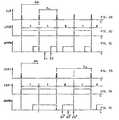
- FIG. 2 aa clock signal received by the transponder, from which a time interval is defined
- FIG. 2 ba binary data stream in the transponder for the encoding of the electromagnetic carrier wave of the base station with respectively one bit per time interval
- FIG. 2 cthe modulation signal for the modulation of the electromagnetic wave
- FIG. 3 aa second clock signal of the base station received by the transponder
- FIG. 3 ba binary data stream in the transponder for the encoding of the electromagnetic carrier wave of the base station with respectively two bits per time interval
- FIG. 3 cthe modulation signal for the modulation of the electromagnetic wave.
- FIG. 1 aAn arrangement for the data transmission between a base station BS and a passive transponder TR is depicted in FIG. 1 a .
- the transponder TRtakes its energy out of the carrier wave of the base station BS.
- Such systemsare used, among other things, in the field of the motor vehicle, whereby the transponder is installed in the door key and the base station BS is installed in the car.
- the base station BScomprises an integrated circuit IC 1 , that controls a transmitting and receiving unit SE 1 with a transmitting part SXT 1 and a receiving part RXT 1 .
- the base stationtransmits or emits a modulated carrier wave, that is received by the transponder TR by means of a transmitting and receiving unit SE 2 , that comprises a receiving part RXT 2 and a transmitting part SXT 2 , and that is directed further to a control unit CON for the evaluation, whereby the transmitting and receiving unit SE 2 furthermore absorbs the energy necessary for the supply of the transponder TR.
- the integrated circuit IC 2consists of the control unit CON and a memory unit SP, in which, among other things, the initial characteristic values of a protocol utilized for the data transmission of information packets are stored.
- an information packet IPconsists of a header section KO, a data region DA, and an end of the text region EOT.
- the number of the symbols and their identificationare defined in the header section KO.
- the header section KOcan be used for the synchronization of the data protocol.
- the data to be transmittedare encoded in the data region with the identification.
- the end of the information packetis communicated or reported to the receiver with the EOT region via a prescribed identification.
- the method according to particular embodimentsis explained by means of a synchronous data transmission.
- the base station BStransmits or emits timing or clock pulses CLK for the synchronization of the data transmission.
- the clock pulses CLKare used as trigger pulses for the demodulation. Furthermore, in the transponder TR, the time duration of two successive pulses is calculated, for example by means of an internal counter, which preferably derives from a system clock of the transponder TR, and is used as a reference length. If the transponder TR recognizes a data transmission, then at the beginning of the data transmission within the control unit CON, the protocol parameters are extracted out of the header section KO of the first incident information packet IP, and for example compared with the protocol values prescribed in the memory unit SP.
- FIGS. 2 a - cthere are illustrated schematic signal progressions or courses in the transponder TR, by means of which the time points of the change of the modulation state of the electromagnetic wave for the transmission of a prescribed binary bit sequence of a reply signal of the transponder TR to the base station BS are derived.
- the time pointsare transmitted from the base station BS to the transponder TR in the header section KO of the information packet in the form of fractional parts of the 20 time interval Tx consisting of two successive clock signals.
- the value 1 ⁇ 3 of the time interval Txis allocated to the logic value “0”
- the value 2 ⁇ 3 of the time interval Txis allocated to the logic value “1”.
- the clock signal CLK of the base station BS received by the transponder TRis illustrated in the FIG. 2 a .
- the clock signals CLKcomprise an equal or uniform interval interspace.
- the transponderdefines for itself a time interval Tx from two successive clock signals CLK.
- a data stream L 2 S 0 that is transmitted back from the transponder TR as part of a data word to the base station BSis depicted in the FIG. 2 b .
- exactly one bit of the bit sequenceis allocated to each time interval Tx.
- the time progression or course of the modulation state UMPNis illustrated in the FIG. 2 c .
- the modulation statechanges within the time interval Tx, either at a time point Z 1 insofar as a logic zero is present, or at a time point Z 2 insofar as a logic one is present.
- a certain constant modulation stateexists, that is to say the direction of the state change of the modulation is predefined or prescribed. For this purpose it is required at the outset, that the modulation state is changed back to the original value at the end of each respective time interval Tx.
- the time axis tis extended or enlarged.
- the time intervals Tyresult respectively from two successive clock pulses CLK 1 .
- the bit sequence L 2 S 1 to be transmittedis illustrated, two data bits are allocated per time interval Ty.
- the time progression or course of the change of the modulation state UMP 01is illustrated in the FIG. 3 c .
- the modulation state for a logic onechanges at a time point Z 2 *, which is given as 2 ⁇ 3 of the half of the duration of the time interval Ty, and for a logic zero at a time point Z 1 * as 1 ⁇ 3 of the half of the duration of the time interval Ty.
- the modulation stateis not changed in the middle of the interval. If the two bits comprise a different logic value, the modulation state is changed at a time point Z 3 *, which corresponds to the middle of the interval Ty.
Landscapes
- Engineering & Computer Science (AREA)
- Physics & Mathematics (AREA)
- Spectroscopy & Molecular Physics (AREA)
- Computer Vision & Pattern Recognition (AREA)
- General Physics & Mathematics (AREA)
- Theoretical Computer Science (AREA)
- Artificial Intelligence (AREA)
- Computer Networks & Wireless Communication (AREA)
- Signal Processing (AREA)
- Near-Field Transmission Systems (AREA)
- Synchronisation In Digital Transmission Systems (AREA)
- Detection And Prevention Of Errors In Transmission (AREA)
- Mobile Radio Communication Systems (AREA)
- Digital Transmission Methods That Use Modulated Carrier Waves (AREA)
Abstract
Description
Claims (20)
Priority Applications (1)
| Application Number | Priority Date | Filing Date | Title |
|---|---|---|---|
| US13/049,764US8315276B2 (en) | 2002-02-01 | 2011-03-16 | Transmitting data between a base station and a transponder |
Applications Claiming Priority (8)
| Application Number | Priority Date | Filing Date | Title |
|---|---|---|---|
| DE10204347ADE10204347A1 (en) | 2002-02-01 | 2002-02-01 | Process for the transmission of data |
| DE10204347.7 | 2002-02-01 | ||
| DE10204347 | 2002-02-01 | ||
| EPPCT/EP03/00312 | 2003-01-15 | ||
| US10/503,256US20050180380A1 (en) | 2002-02-01 | 2003-01-15 | Method for transmitting data |
| PCT/EP2003/000312WO2003065284A1 (en) | 2002-02-01 | 2003-01-15 | Method for transmitting data |
| WOPCT/EP03/00312 | 2003-01-15 | ||
| US13/049,764US8315276B2 (en) | 2002-02-01 | 2011-03-16 | Transmitting data between a base station and a transponder |
Related Parent Applications (1)
| Application Number | Title | Priority Date | Filing Date |
|---|---|---|---|
| US10/503,256ContinuationUS20050180380A1 (en) | 2002-02-01 | 2003-01-15 | Method for transmitting data |
Publications (2)
| Publication Number | Publication Date |
|---|---|
| US20110217924A1 US20110217924A1 (en) | 2011-09-08 |
| US8315276B2true US8315276B2 (en) | 2012-11-20 |
Family
ID=27588308
Family Applications (2)
| Application Number | Title | Priority Date | Filing Date |
|---|---|---|---|
| US10/503,256AbandonedUS20050180380A1 (en) | 2002-02-01 | 2003-01-15 | Method for transmitting data |
| US13/049,764Expired - Fee RelatedUS8315276B2 (en) | 2002-02-01 | 2011-03-16 | Transmitting data between a base station and a transponder |
Family Applications Before (1)
| Application Number | Title | Priority Date | Filing Date |
|---|---|---|---|
| US10/503,256AbandonedUS20050180380A1 (en) | 2002-02-01 | 2003-01-15 | Method for transmitting data |
Country Status (4)
| Country | Link |
|---|---|
| US (2) | US20050180380A1 (en) |
| EP (1) | EP1470521B1 (en) |
| DE (2) | DE10204347A1 (en) |
| WO (1) | WO2003065284A1 (en) |
Families Citing this family (9)
| Publication number | Priority date | Publication date | Assignee | Title |
|---|---|---|---|---|
| DE10335003A1 (en) | 2003-07-23 | 2005-02-10 | Atmel Germany Gmbh | Wireless transmission system between base station and transponder is for stream of data and uses starter signal followed by main body of signal and end signal |
| DE10335009A1 (en) | 2003-07-23 | 2005-02-10 | Atmel Germany Gmbh | Method for wireless data transmission between a base station and a transponder |
| DE102004013885B4 (en)* | 2004-03-16 | 2012-08-30 | Atmel Automotive Gmbh | Method and modulation control device for wireless data transmission |
| DE102004018555B4 (en) | 2004-03-25 | 2007-10-11 | Atmel Germany Gmbh | Method for data communication between a base station and a transponder, base station for data communication and data communication system |
| DE102004016335B4 (en)* | 2004-04-02 | 2019-06-13 | Infineon Technologies Ag | Method for contactless data transmission |
| DE102004019309A1 (en) | 2004-04-14 | 2005-11-03 | Atmel Germany Gmbh | Method for wireless data transmission |
| DE102004018539A1 (en)* | 2004-04-14 | 2005-11-03 | Atmel Germany Gmbh | Method for data communication between a base station and a transponder |
| US20070058584A1 (en)* | 2005-09-12 | 2007-03-15 | Ilan Sutskover | Techniques to transmit and duplex with channel knowledge at a base station |
| US12352805B2 (en)* | 2020-09-17 | 2025-07-08 | Wiliot, LTD. | System and method for testing IoT tags |
Citations (28)
| Publication number | Priority date | Publication date | Assignee | Title |
|---|---|---|---|---|
| DE1001058B (en) | 1953-01-27 | 1957-01-17 | Ft Products Ltd | Device for securing flexible material to a pipe by means of a number of flexible, one-piece clips |
| US3257644A (en) | 1962-07-09 | 1966-06-21 | Moore Associates Inc | Encoding system and method |
| US3564412A (en) | 1968-03-01 | 1971-02-16 | Milgo Electronic Corp | Derived clock from carrier envelope |
| US4007329A (en)* | 1976-02-12 | 1977-02-08 | Ncr Corporation | Data communications system with improved asynchronous retiming circuit |
| US4631538A (en) | 1983-02-28 | 1986-12-23 | The United States Of America As Represented By The Administrator Of The National Aeronautics And Space Administration | Single frequency multitransmitter telemetry system |
| US5084871A (en)* | 1987-10-16 | 1992-01-28 | Digital Equipment Corporation | Flow control of messages in a local area network |
| EP0473569A2 (en) | 1990-08-23 | 1992-03-04 | Mikron Gesellschaft Für Integrierte Mikroelektronik Mbh | Contactless, inductive data transmission system |
| EP0542229A1 (en) | 1991-11-12 | 1993-05-19 | Dai Nippon Printing Co., Ltd. | Data transfer method for use in semiconductor data recording medium |
| US5450492A (en) | 1990-05-01 | 1995-09-12 | Disys Corporation | Transponder system with variable frequency transmission |
| US5526357A (en)* | 1991-08-16 | 1996-06-11 | Pinpoint Communications, Inc. | Communication system and method for determining the location of a transponder unit |
| US5828658A (en)* | 1991-12-12 | 1998-10-27 | Arraycomm, Inc. | Spectrally efficient high capacity wireless communication systems with spatio-temporal processing |
| US5852634A (en) | 1992-08-21 | 1998-12-22 | U.S. Philips Corporation | Data coding system |
| US5856975A (en)* | 1993-10-20 | 1999-01-05 | Lsi Logic Corporation | High speed single chip digital video network apparatus |
| DE19744784A1 (en) | 1997-10-10 | 1999-05-06 | Gsf Forschungszentrum Umwelt | Sensor for water content determination |
| US5969631A (en) | 1996-06-14 | 1999-10-19 | Temic Telefunken Microelectronic Gmbh | Method and control system for the synchronized transmission of digital data |
| US6044333A (en) | 1997-10-10 | 2000-03-28 | Anatoli Stobbe | Process and device to transmit data between a read/write device and a transponder |
| US6147719A (en) | 1996-12-30 | 2000-11-14 | Mitsubishi Digital Electronics America, Inc. | Pulse position modulation protocol |
| DE19927320A1 (en) | 1999-06-15 | 2000-12-21 | Mannesmann Vdo Ag | Method for wireless electromagnetic transmission of data |
| US6212230B1 (en) | 1998-04-04 | 2001-04-03 | Sigmatel, Inc. | Method and apparatus for pulse position modulation |
| US20010019303A1 (en) | 2000-03-03 | 2001-09-06 | Michael Bruhnke | Method for transmission of data |
| US20020150123A1 (en)* | 2001-04-11 | 2002-10-17 | Cyber Operations, Llc | System and method for network delivery of low bit rate multimedia content |
| US20020163976A1 (en) | 2001-05-04 | 2002-11-07 | Atmel Germany Gmbh | Method for transmitting data |
| US20020191712A1 (en)* | 2001-04-02 | 2002-12-19 | Koninklijke Philips Electronics N.V. | Packet identification mechanism at the transmitter and receiver for an enhanced ATSC 8-VSB system |
| US6510150B1 (en) | 1998-12-21 | 2003-01-21 | Koninklijke Philips Electronics N.V. | Method of MAC synchronization in TDMA-based wireless networks |
| DE10138217A1 (en) | 2001-08-03 | 2003-03-20 | Atmel Germany Gmbh | Process for the transmission of data |
| US6590881B1 (en)* | 1998-12-04 | 2003-07-08 | Qualcomm, Incorporated | Method and apparatus for providing wireless communication system synchronization |
| US20030137968A1 (en)* | 2002-01-18 | 2003-07-24 | Lareau Neil William | Monitoring and tracking of assets by utilizing wireless communications |
| US7027773B1 (en) | 1999-05-28 | 2006-04-11 | Afx Technology Group International, Inc. | On/off keying node-to-node messaging transceiver network with dynamic routing and configuring |
- 2002
- 2002-02-01DEDE10204347Apatent/DE10204347A1/ennot_activeWithdrawn
- 2003
- 2003-01-15USUS10/503,256patent/US20050180380A1/ennot_activeAbandoned
- 2003-01-15WOPCT/EP2003/000312patent/WO2003065284A1/enactiveIP Right Grant
- 2003-01-15EPEP03734597Apatent/EP1470521B1/ennot_activeExpired - Lifetime
- 2003-01-15DEDE50301357Tpatent/DE50301357D1/ennot_activeExpired - Lifetime
- 2011
- 2011-03-16USUS13/049,764patent/US8315276B2/ennot_activeExpired - Fee Related
Patent Citations (32)
| Publication number | Priority date | Publication date | Assignee | Title |
|---|---|---|---|---|
| DE1001058B (en) | 1953-01-27 | 1957-01-17 | Ft Products Ltd | Device for securing flexible material to a pipe by means of a number of flexible, one-piece clips |
| US3257644A (en) | 1962-07-09 | 1966-06-21 | Moore Associates Inc | Encoding system and method |
| US3564412A (en) | 1968-03-01 | 1971-02-16 | Milgo Electronic Corp | Derived clock from carrier envelope |
| US4007329A (en)* | 1976-02-12 | 1977-02-08 | Ncr Corporation | Data communications system with improved asynchronous retiming circuit |
| US4631538A (en) | 1983-02-28 | 1986-12-23 | The United States Of America As Represented By The Administrator Of The National Aeronautics And Space Administration | Single frequency multitransmitter telemetry system |
| US5084871A (en)* | 1987-10-16 | 1992-01-28 | Digital Equipment Corporation | Flow control of messages in a local area network |
| US5450492A (en) | 1990-05-01 | 1995-09-12 | Disys Corporation | Transponder system with variable frequency transmission |
| EP0473569A2 (en) | 1990-08-23 | 1992-03-04 | Mikron Gesellschaft Für Integrierte Mikroelektronik Mbh | Contactless, inductive data transmission system |
| US5526357A (en)* | 1991-08-16 | 1996-06-11 | Pinpoint Communications, Inc. | Communication system and method for determining the location of a transponder unit |
| US5362954A (en) | 1991-11-12 | 1994-11-08 | Dai Nippon Printing Co., Ltd. | Data transfer method for use in semiconductor data recording medium |
| EP0542229A1 (en) | 1991-11-12 | 1993-05-19 | Dai Nippon Printing Co., Ltd. | Data transfer method for use in semiconductor data recording medium |
| US5828658A (en)* | 1991-12-12 | 1998-10-27 | Arraycomm, Inc. | Spectrally efficient high capacity wireless communication systems with spatio-temporal processing |
| US5852634A (en) | 1992-08-21 | 1998-12-22 | U.S. Philips Corporation | Data coding system |
| US5856975A (en)* | 1993-10-20 | 1999-01-05 | Lsi Logic Corporation | High speed single chip digital video network apparatus |
| US5969631A (en) | 1996-06-14 | 1999-10-19 | Temic Telefunken Microelectronic Gmbh | Method and control system for the synchronized transmission of digital data |
| US6147719A (en) | 1996-12-30 | 2000-11-14 | Mitsubishi Digital Electronics America, Inc. | Pulse position modulation protocol |
| US6044333A (en) | 1997-10-10 | 2000-03-28 | Anatoli Stobbe | Process and device to transmit data between a read/write device and a transponder |
| DE19744784A1 (en) | 1997-10-10 | 1999-05-06 | Gsf Forschungszentrum Umwelt | Sensor for water content determination |
| US6212230B1 (en) | 1998-04-04 | 2001-04-03 | Sigmatel, Inc. | Method and apparatus for pulse position modulation |
| US6590881B1 (en)* | 1998-12-04 | 2003-07-08 | Qualcomm, Incorporated | Method and apparatus for providing wireless communication system synchronization |
| US6510150B1 (en) | 1998-12-21 | 2003-01-21 | Koninklijke Philips Electronics N.V. | Method of MAC synchronization in TDMA-based wireless networks |
| US7027773B1 (en) | 1999-05-28 | 2006-04-11 | Afx Technology Group International, Inc. | On/off keying node-to-node messaging transceiver network with dynamic routing and configuring |
| DE19927320A1 (en) | 1999-06-15 | 2000-12-21 | Mannesmann Vdo Ag | Method for wireless electromagnetic transmission of data |
| US20010019303A1 (en) | 2000-03-03 | 2001-09-06 | Michael Bruhnke | Method for transmission of data |
| DE10010585A1 (en) | 2000-03-03 | 2001-09-13 | Atmel Germany Gmbh | Process for the transmission of data |
| US20020191712A1 (en)* | 2001-04-02 | 2002-12-19 | Koninklijke Philips Electronics N.V. | Packet identification mechanism at the transmitter and receiver for an enhanced ATSC 8-VSB system |
| US20020150123A1 (en)* | 2001-04-11 | 2002-10-17 | Cyber Operations, Llc | System and method for network delivery of low bit rate multimedia content |
| US20020163976A1 (en) | 2001-05-04 | 2002-11-07 | Atmel Germany Gmbh | Method for transmitting data |
| DE10121855A1 (en) | 2001-05-04 | 2003-02-13 | Atmel Germany Gmbh | Process for the transmission of data |
| DE10138217A1 (en) | 2001-08-03 | 2003-03-20 | Atmel Germany Gmbh | Process for the transmission of data |
| US20030133435A1 (en) | 2001-08-03 | 2003-07-17 | Atmel Germany Gmbh | Method of transmitting data with optimized transmission rate using packet header that defines data encoding parameters |
| US20030137968A1 (en)* | 2002-01-18 | 2003-07-24 | Lareau Neil William | Monitoring and tracking of assets by utilizing wireless communications |
Also Published As
| Publication number | Publication date |
|---|---|
| US20050180380A1 (en) | 2005-08-18 |
| DE10204347A1 (en) | 2003-08-14 |
| WO2003065284A1 (en) | 2003-08-07 |
| EP1470521A1 (en) | 2004-10-27 |
| EP1470521B1 (en) | 2005-10-12 |
| US20110217924A1 (en) | 2011-09-08 |
| DE50301357D1 (en) | 2006-02-23 |
Similar Documents
| Publication | Publication Date | Title |
|---|---|---|
| US8315276B2 (en) | Transmitting data between a base station and a transponder | |
| US7385950B2 (en) | Method of transmitting data with optimized transmission rate using packet header that defines data encoding parameters | |
| US5377222A (en) | Frequency agile radio | |
| US7986653B2 (en) | Wireless data transmission between base station and transponder with transmission parameter adjusted based on transponder operating information | |
| US5311541A (en) | Frequency agile radio | |
| US4479215A (en) | Power-line carrier communications system with interference avoidance capability | |
| US8577295B2 (en) | Method and apparatus for data communication between a base station and a transponder | |
| EP0783211A2 (en) | Remote meter reading system | |
| US9350577B2 (en) | Communication method and device | |
| US20020163976A1 (en) | Method for transmitting data | |
| US6882826B2 (en) | Process for the transfer of data | |
| US8432255B2 (en) | Secondary data channels in RFID systems | |
| US7336695B1 (en) | m-ary variable shift keying communications system | |
| US9165169B2 (en) | Method for data communication between a base station and a transponder | |
| JP2006246485A (en) | Selection method for data communication between base station and transponders | |
| US20140036902A1 (en) | Method, Apparatus, and Logic for Wireless Data Transmission | |
| US6134275A (en) | Method for transmitting data between a terminal and a portable data carrier over a wireless electromagnetic transmission link | |
| EP0845751B1 (en) | A transponder system | |
| EP1111805B1 (en) | Frequency agile radio reception | |
| US20070030921A1 (en) | Method for data communication between a base station and a transponder | |
| JP3829303B2 (en) | Data transmission method | |
| MXPA99001742A (en) | Data transmission by impulse position modulation and amplitude modulation |
Legal Events
| Date | Code | Title | Description |
|---|---|---|---|
| AS | Assignment | Owner name:ATMEL CORPORATION, CALIFORNIA Free format text:ASSIGNMENT OF ASSIGNORS INTEREST;ASSIGNOR:ATMEL AUTOMOTIVE GMBH;REEL/FRAME:029025/0240 Effective date:20110228 Owner name:ATMEL AUTOMOTIVE GMBH, GERMANY Free format text:ASSIGNMENT OF ASSIGNORS INTEREST;ASSIGNOR:ATMEL GERMANY GMBH;REEL/FRAME:029025/0164 Effective date:20081205 Owner name:ATMEL GERMANY GMBH, GERMANY Free format text:ASSIGNMENT OF ASSIGNORS INTEREST;ASSIGNOR:FRIEDRICH, ULRICH;REEL/FRAME:029025/0162 Effective date:20040715 | |
| STCF | Information on status: patent grant | Free format text:PATENTED CASE | |
| AS | Assignment | Owner name:MORGAN STANLEY SENIOR FUNDING, INC. AS ADMINISTRATIVE AGENT, NEW YORK Free format text:PATENT SECURITY AGREEMENT;ASSIGNOR:ATMEL CORPORATION;REEL/FRAME:031912/0173 Effective date:20131206 Owner name:MORGAN STANLEY SENIOR FUNDING, INC. AS ADMINISTRAT Free format text:PATENT SECURITY AGREEMENT;ASSIGNOR:ATMEL CORPORATION;REEL/FRAME:031912/0173 Effective date:20131206 | |
| AS | Assignment | Owner name:ATMEL CORPORATION, CALIFORNIA Free format text:TERMINATION AND RELEASE OF SECURITY INTEREST IN PATENT COLLATERAL;ASSIGNOR:MORGAN STANLEY SENIOR FUNDING, INC.;REEL/FRAME:038376/0001 Effective date:20160404 | |
| FPAY | Fee payment | Year of fee payment:4 | |
| AS | Assignment | Owner name:JPMORGAN CHASE BANK, N.A., AS ADMINISTRATIVE AGENT, ILLINOIS Free format text:SECURITY INTEREST;ASSIGNOR:ATMEL CORPORATION;REEL/FRAME:041715/0747 Effective date:20170208 Owner name:JPMORGAN CHASE BANK, N.A., AS ADMINISTRATIVE AGENT Free format text:SECURITY INTEREST;ASSIGNOR:ATMEL CORPORATION;REEL/FRAME:041715/0747 Effective date:20170208 | |
| AS | Assignment | Owner name:JPMORGAN CHASE BANK, N.A., AS ADMINISTRATIVE AGENT, ILLINOIS Free format text:SECURITY INTEREST;ASSIGNORS:MICROCHIP TECHNOLOGY INCORPORATED;SILICON STORAGE TECHNOLOGY, INC.;ATMEL CORPORATION;AND OTHERS;REEL/FRAME:046426/0001 Effective date:20180529 Owner name:JPMORGAN CHASE BANK, N.A., AS ADMINISTRATIVE AGENT Free format text:SECURITY INTEREST;ASSIGNORS:MICROCHIP TECHNOLOGY INCORPORATED;SILICON STORAGE TECHNOLOGY, INC.;ATMEL CORPORATION;AND OTHERS;REEL/FRAME:046426/0001 Effective date:20180529 | |
| AS | Assignment | Owner name:WELLS FARGO BANK, NATIONAL ASSOCIATION, AS NOTES COLLATERAL AGENT, CALIFORNIA Free format text:SECURITY INTEREST;ASSIGNORS:MICROCHIP TECHNOLOGY INCORPORATED;SILICON STORAGE TECHNOLOGY, INC.;ATMEL CORPORATION;AND OTHERS;REEL/FRAME:047103/0206 Effective date:20180914 Owner name:WELLS FARGO BANK, NATIONAL ASSOCIATION, AS NOTES C Free format text:SECURITY INTEREST;ASSIGNORS:MICROCHIP TECHNOLOGY INCORPORATED;SILICON STORAGE TECHNOLOGY, INC.;ATMEL CORPORATION;AND OTHERS;REEL/FRAME:047103/0206 Effective date:20180914 | |
| AS | Assignment | Owner name:JPMORGAN CHASE BANK, N.A., AS ADMINISTRATIVE AGENT, DELAWARE Free format text:SECURITY INTEREST;ASSIGNORS:MICROCHIP TECHNOLOGY INC.;SILICON STORAGE TECHNOLOGY, INC.;ATMEL CORPORATION;AND OTHERS;REEL/FRAME:053311/0305 Effective date:20200327 | |
| AS | Assignment | Owner name:MICROSEMI CORPORATION, CALIFORNIA Free format text:RELEASE BY SECURED PARTY;ASSIGNOR:JPMORGAN CHASE BANK, N.A, AS ADMINISTRATIVE AGENT;REEL/FRAME:053466/0011 Effective date:20200529 Owner name:SILICON STORAGE TECHNOLOGY, INC., ARIZONA Free format text:RELEASE BY SECURED PARTY;ASSIGNOR:JPMORGAN CHASE BANK, N.A, AS ADMINISTRATIVE AGENT;REEL/FRAME:053466/0011 Effective date:20200529 Owner name:ATMEL CORPORATION, ARIZONA Free format text:RELEASE BY SECURED PARTY;ASSIGNOR:JPMORGAN CHASE BANK, N.A, AS ADMINISTRATIVE AGENT;REEL/FRAME:053466/0011 Effective date:20200529 Owner name:MICROCHIP TECHNOLOGY INC., ARIZONA Free format text:RELEASE BY SECURED PARTY;ASSIGNOR:JPMORGAN CHASE BANK, N.A, AS ADMINISTRATIVE AGENT;REEL/FRAME:053466/0011 Effective date:20200529 Owner name:MICROSEMI STORAGE SOLUTIONS, INC., ARIZONA Free format text:RELEASE BY SECURED PARTY;ASSIGNOR:JPMORGAN CHASE BANK, N.A, AS ADMINISTRATIVE AGENT;REEL/FRAME:053466/0011 Effective date:20200529 | |
| AS | Assignment | Owner name:WELLS FARGO BANK, NATIONAL ASSOCIATION, MINNESOTA Free format text:SECURITY INTEREST;ASSIGNORS:MICROCHIP TECHNOLOGY INC.;SILICON STORAGE TECHNOLOGY, INC.;ATMEL CORPORATION;AND OTHERS;REEL/FRAME:053468/0705 Effective date:20200529 | |
| FEPP | Fee payment procedure | Free format text:MAINTENANCE FEE REMINDER MAILED (ORIGINAL EVENT CODE: REM.); ENTITY STATUS OF PATENT OWNER: LARGE ENTITY | |
| AS | Assignment | Owner name:WELLS FARGO BANK, NATIONAL ASSOCIATION, AS COLLATERAL AGENT, MINNESOTA Free format text:SECURITY INTEREST;ASSIGNORS:MICROCHIP TECHNOLOGY INCORPORATED;SILICON STORAGE TECHNOLOGY, INC.;ATMEL CORPORATION;AND OTHERS;REEL/FRAME:055671/0612 Effective date:20201217 | |
| LAPS | Lapse for failure to pay maintenance fees | Free format text:PATENT EXPIRED FOR FAILURE TO PAY MAINTENANCE FEES (ORIGINAL EVENT CODE: EXP.); ENTITY STATUS OF PATENT OWNER: LARGE ENTITY | |
| STCH | Information on status: patent discontinuation | Free format text:PATENT EXPIRED DUE TO NONPAYMENT OF MAINTENANCE FEES UNDER 37 CFR 1.362 | |
| FP | Lapsed due to failure to pay maintenance fee | Effective date:20201120 | |
| AS | Assignment | Owner name:MICROSEMI STORAGE SOLUTIONS, INC., ARIZONA Free format text:RELEASE BY SECURED PARTY;ASSIGNOR:JPMORGAN CHASE BANK, N.A., AS ADMINISTRATIVE AGENT;REEL/FRAME:059333/0222 Effective date:20220218 Owner name:MICROSEMI CORPORATION, ARIZONA Free format text:RELEASE BY SECURED PARTY;ASSIGNOR:JPMORGAN CHASE BANK, N.A., AS ADMINISTRATIVE AGENT;REEL/FRAME:059333/0222 Effective date:20220218 Owner name:ATMEL CORPORATION, ARIZONA Free format text:RELEASE BY SECURED PARTY;ASSIGNOR:JPMORGAN CHASE BANK, N.A., AS ADMINISTRATIVE AGENT;REEL/FRAME:059333/0222 Effective date:20220218 Owner name:SILICON STORAGE TECHNOLOGY, INC., ARIZONA Free format text:RELEASE BY SECURED PARTY;ASSIGNOR:JPMORGAN CHASE BANK, N.A., AS ADMINISTRATIVE AGENT;REEL/FRAME:059333/0222 Effective date:20220218 Owner name:MICROCHIP TECHNOLOGY INCORPORATED, ARIZONA Free format text:RELEASE BY SECURED PARTY;ASSIGNOR:JPMORGAN CHASE BANK, N.A., AS ADMINISTRATIVE AGENT;REEL/FRAME:059333/0222 Effective date:20220218 | |
| AS | Assignment | Owner name:ATMEL CORPORATION, ARIZONA Free format text:RELEASE BY SECURED PARTY;ASSIGNOR:JPMORGAN CHASE BANK, N.A., AS ADMINISTRATIVE AGENT;REEL/FRAME:059262/0105 Effective date:20220218 | |
| AS | Assignment | Owner name:MICROSEMI STORAGE SOLUTIONS, INC., ARIZONA Free format text:RELEASE BY SECURED PARTY;ASSIGNOR:WELLS FARGO BANK, NATIONAL ASSOCIATION, AS NOTES COLLATERAL AGENT;REEL/FRAME:059358/0001 Effective date:20220228 Owner name:MICROSEMI CORPORATION, ARIZONA Free format text:RELEASE BY SECURED PARTY;ASSIGNOR:WELLS FARGO BANK, NATIONAL ASSOCIATION, AS NOTES COLLATERAL AGENT;REEL/FRAME:059358/0001 Effective date:20220228 Owner name:ATMEL CORPORATION, ARIZONA Free format text:RELEASE BY SECURED PARTY;ASSIGNOR:WELLS FARGO BANK, NATIONAL ASSOCIATION, AS NOTES COLLATERAL AGENT;REEL/FRAME:059358/0001 Effective date:20220228 Owner name:SILICON STORAGE TECHNOLOGY, INC., ARIZONA Free format text:RELEASE BY SECURED PARTY;ASSIGNOR:WELLS FARGO BANK, NATIONAL ASSOCIATION, AS NOTES COLLATERAL AGENT;REEL/FRAME:059358/0001 Effective date:20220228 Owner name:MICROCHIP TECHNOLOGY INCORPORATED, ARIZONA Free format text:RELEASE BY SECURED PARTY;ASSIGNOR:WELLS FARGO BANK, NATIONAL ASSOCIATION, AS NOTES COLLATERAL AGENT;REEL/FRAME:059358/0001 Effective date:20220228 | |
| AS | Assignment | Owner name:MICROSEMI STORAGE SOLUTIONS, INC., ARIZONA Free format text:RELEASE BY SECURED PARTY;ASSIGNOR:WELLS FARGO BANK, NATIONAL ASSOCIATION, AS NOTES COLLATERAL AGENT;REEL/FRAME:059863/0400 Effective date:20220228 Owner name:MICROSEMI CORPORATION, ARIZONA Free format text:RELEASE BY SECURED PARTY;ASSIGNOR:WELLS FARGO BANK, NATIONAL ASSOCIATION, AS NOTES COLLATERAL AGENT;REEL/FRAME:059863/0400 Effective date:20220228 Owner name:ATMEL CORPORATION, ARIZONA Free format text:RELEASE BY SECURED PARTY;ASSIGNOR:WELLS FARGO BANK, NATIONAL ASSOCIATION, AS NOTES COLLATERAL AGENT;REEL/FRAME:059863/0400 Effective date:20220228 Owner name:SILICON STORAGE TECHNOLOGY, INC., ARIZONA Free format text:RELEASE BY SECURED PARTY;ASSIGNOR:WELLS FARGO BANK, NATIONAL ASSOCIATION, AS NOTES COLLATERAL AGENT;REEL/FRAME:059863/0400 Effective date:20220228 Owner name:MICROCHIP TECHNOLOGY INCORPORATED, ARIZONA Free format text:RELEASE BY SECURED PARTY;ASSIGNOR:WELLS FARGO BANK, NATIONAL ASSOCIATION, AS NOTES COLLATERAL AGENT;REEL/FRAME:059863/0400 Effective date:20220228 | |
| AS | Assignment | Owner name:MICROSEMI STORAGE SOLUTIONS, INC., ARIZONA Free format text:RELEASE BY SECURED PARTY;ASSIGNOR:WELLS FARGO BANK, NATIONAL ASSOCIATION, AS NOTES COLLATERAL AGENT;REEL/FRAME:059363/0001 Effective date:20220228 Owner name:MICROSEMI CORPORATION, ARIZONA Free format text:RELEASE BY SECURED PARTY;ASSIGNOR:WELLS FARGO BANK, NATIONAL ASSOCIATION, AS NOTES COLLATERAL AGENT;REEL/FRAME:059363/0001 Effective date:20220228 Owner name:ATMEL CORPORATION, ARIZONA Free format text:RELEASE BY SECURED PARTY;ASSIGNOR:WELLS FARGO BANK, NATIONAL ASSOCIATION, AS NOTES COLLATERAL AGENT;REEL/FRAME:059363/0001 Effective date:20220228 Owner name:SILICON STORAGE TECHNOLOGY, INC., ARIZONA Free format text:RELEASE BY SECURED PARTY;ASSIGNOR:WELLS FARGO BANK, NATIONAL ASSOCIATION, AS NOTES COLLATERAL AGENT;REEL/FRAME:059363/0001 Effective date:20220228 Owner name:MICROCHIP TECHNOLOGY INCORPORATED, ARIZONA Free format text:RELEASE BY SECURED PARTY;ASSIGNOR:WELLS FARGO BANK, NATIONAL ASSOCIATION, AS NOTES COLLATERAL AGENT;REEL/FRAME:059363/0001 Effective date:20220228 | |
| AS | Assignment | Owner name:MICROSEMI STORAGE SOLUTIONS, INC., ARIZONA Free format text:RELEASE BY SECURED PARTY;ASSIGNOR:WELLS FARGO BANK, NATIONAL ASSOCIATION, AS NOTES COLLATERAL AGENT;REEL/FRAME:060894/0437 Effective date:20220228 Owner name:MICROSEMI CORPORATION, ARIZONA Free format text:RELEASE BY SECURED PARTY;ASSIGNOR:WELLS FARGO BANK, NATIONAL ASSOCIATION, AS NOTES COLLATERAL AGENT;REEL/FRAME:060894/0437 Effective date:20220228 Owner name:ATMEL CORPORATION, ARIZONA Free format text:RELEASE BY SECURED PARTY;ASSIGNOR:WELLS FARGO BANK, NATIONAL ASSOCIATION, AS NOTES COLLATERAL AGENT;REEL/FRAME:060894/0437 Effective date:20220228 Owner name:SILICON STORAGE TECHNOLOGY, INC., ARIZONA Free format text:RELEASE BY SECURED PARTY;ASSIGNOR:WELLS FARGO BANK, NATIONAL ASSOCIATION, AS NOTES COLLATERAL AGENT;REEL/FRAME:060894/0437 Effective date:20220228 Owner name:MICROCHIP TECHNOLOGY INCORPORATED, ARIZONA Free format text:RELEASE BY SECURED PARTY;ASSIGNOR:WELLS FARGO BANK, NATIONAL ASSOCIATION, AS NOTES COLLATERAL AGENT;REEL/FRAME:060894/0437 Effective date:20220228 |