US8315202B1 - Synchronized code recognition - Google Patents
Synchronized code recognitionDownload PDFInfo
- Publication number
- US8315202B1 US8315202B1US12/467,909US46790909AUS8315202B1US 8315202 B1US8315202 B1US 8315202B1US 46790909 AUS46790909 AUS 46790909AUS 8315202 B1US8315202 B1US 8315202B1
- Authority
- US
- United States
- Prior art keywords
- clock signal
- satellite
- controller
- internal clock
- synchronous
- Prior art date
- Legal status (The legal status is an assumption and is not a legal conclusion. Google has not performed a legal analysis and makes no representation as to the accuracy of the status listed.)
- Active, expires
Links
Images


Classifications
- H—ELECTRICITY
- H04—ELECTRIC COMMUNICATION TECHNIQUE
- H04B—TRANSMISSION
- H04B7/00—Radio transmission systems, i.e. using radiation field
- H04B7/14—Relay systems
- H04B7/15—Active relay systems
- H04B7/204—Multiple access
- H04B7/212—Time-division multiple access [TDMA]
- H04B7/2125—Synchronisation
- H04B7/2126—Synchronisation using a reference station
- H—ELECTRICITY
- H04—ELECTRIC COMMUNICATION TECHNIQUE
- H04W—WIRELESS COMMUNICATION NETWORKS
- H04W56/00—Synchronisation arrangements
- H04W56/0005—Synchronisation arrangements synchronizing of arrival of multiple uplinks
- H—ELECTRICITY
- H04—ELECTRIC COMMUNICATION TECHNIQUE
- H04W—WIRELESS COMMUNICATION NETWORKS
- H04W56/00—Synchronisation arrangements
- H04W56/001—Synchronization between nodes
- H04W56/002—Mutual synchronization
- H—ELECTRICITY
- H04—ELECTRIC COMMUNICATION TECHNIQUE
- H04W—WIRELESS COMMUNICATION NETWORKS
- H04W56/00—Synchronisation arrangements
- H04W56/001—Synchronization between nodes
- H04W56/0025—Synchronization between nodes synchronizing potentially movable access points
Definitions
- Embodiments of the present inventionrelate to the field of device control and, in particular, to the remote control of devices in a time division multiplexed network.
- Remote control systemsare used in applications such as home control, building automation and industrial automation.
- a central controlleris used to control multiple satellite controllers on a network, which in turn control peripheral devices, systems or subsystems.
- Each satellite controllerhas a unique address on the network so it can be individually polled and/or controlled by the central controller.
- One problem common to these remote control systemsis the need to keep the satellite controllers in an active state, ready to receive polling and/or control data, or in a sleep state from which the satellite controllers must first be awakened. Maintaining the satellite controllers in an active state requires power, so there is a constant power overhead cost associated with these systems. If the controllers are battery operated, the power requirements associated with the active state result in shortened battery life and higher system maintenance activity and costs.
- the satellite controllersare kept in a sleep or standby state, they may have to be powered up before they can be polled for status or receive control commands, which also increases power consumption.
- Another problem with existing systemsarises when there are large numbers of satellite controllers, each with time-critical tasks that may have to be coordinated with the central controller or other satellite controllers. To maintain synchronization, satellite controllers in a standby or sleep state may have to be awakened regularly, resulting in higher power consumption as noted above. Alternatively, each satellite controller might require a very accurate local time base, adding to the cost of the system as well as increasing the power consumption of the system.
- Existing systemsdo not provide a mechanism for verifying clock synchronization without awakening the satellite controllers and/or the peripheral devices they control.
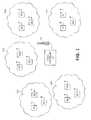
- FIG. 1illustrates one embodiment of a synchronized auto wake-up time division multiplexed network
- FIG. 2illustrates a synchronization code timing diagram in one embodiment
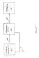
- FIG. 3illustrates a central controller in one embodiment of a synchronized auto wake-up time division multiplexed network
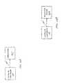
- FIG. 4illustrates a satellite controller in one embodiment of a synchronized auto wake-up time division multiplexed network
- FIG. 5illustrates one embodiment of synchronized auto-wakeup in a time division multiplexed network.
- FIG. 6Aillustrates an auto-response device in an embodiment of a synchronized auto wake-up time division multiplexed network
- FIG. 6Billustrates one embodiment of auto-wake-up in a synchronized auto wake-up time division multiplexed network
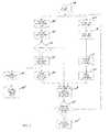
- FIG. 7is a flowchart illustrating one embodiment of a method for a synchronized auto wake-up time division multiplexed network.
- lines and/or other coupling elementsmay be identified by the nature of the signals they carry (e.g., a “clock line” may implicitly carry a “clock signal”) and that input and output ports may be identified by the nature of the signals they receive or transmit (e.g., “clock input” may implicitly receive a “clock signal”).
- a systemincludes a central controller to transmit a plurality of synchronization codes over a transmission medium, and a plurality of satellite controllers to receive the synchronization codes.
- Each satellite controlleris configured to recognize one or more of the synchronization codes and includes a synchronous clock signal generator to generate a synchronous clock signal when the satellite controller recognizes the one or more synchronization codes.
- the plurality of satellite controllersmay include one or more groups of satellite controllers and each group of satellite controllers may be configured to recognize a different synchronization code.
- Each satellite controller in a group of satellite controllersmay be configured to recognize the same synchronization code and to generate a synchronous clock signal in response thereto.
- Each satellite controller in a group of satellite controllersmay also include a programmable tuner, coupled to and triggered by the synchronous clock signal generator, wherein each programmable timer times a response from the satellite controller to the central controller.
- the response of the satellite controllermay be timed to avoid interference with a response from any other satellite controller in the satellite controller group and with any other satellite controller in any other satellite controller group.
- the plurality of synchronization signalsmay be periodic signals
- each satellite controllermay include an internal clock signal generator to generate an internal clock signal.
- Each satellite controllermay also include a synchronous comparator to count the synchronous clock signal and the internal clock signal, to compare an internal clock signal count with a synchronous clock signal count and to wake-up a peripheral device if a difference between the internal clock signal count and the synchronous clock signal count exceeds a programmed value.
- a satellite controllermay include one or more programmable timers coupled to the synchronous comparator and the internal clock generator.
- the one or more programmable timersmay be triggered by the synchronous clock signal and clocked by an internal clock signal, wherein the programmable timer may switch one or more peripheral devices between a first state and a second state after a programmed delay.
- the systemmay include a central controller 101 and a plurality of satellite controllers 102 , which may be organized into one or more groups of satellite controllers 103 - 1 through 103 - n . Each group of satellite controllers 103 - 1 through 103 - n may include one or more satellite controllers 102 .
- the central controller 101may be configured to transmit a series of time division multiplexed synchronization codes 104 , as illustrated in FIG. 2 , including synchronization codes 104 - 1 through 104 - n , which may be an aperiodic series of synchronization codes or a periodic series of synchronization codes.
- Each satellite controller 102may be configured to recognize one or more synchronization codes 104 - 1 through 104 - n .
- the synchronization codes 104 - 1 through 104 - nmay be transmitted wirelessly by a radio antenna 105 coupled to central controller 101 , as shown by way of example in FIG. 1 .
- the synchronization codes 104 - 1 through 104 - nmay be transmitted by any other means over any kind of wired or wireless transmission medium, including, for example, optical means and media such as infrared transducers and optical fibers, acoustic means and media such as conventional speakers and microphones or piezoelectric transducers, and cabled means and media such as conventional twisted pair cable or conventional home or industrial power wiring.
- each satellite controller 102 in a group of satellite controllers 103may be configured to recognize the same synchronization code.
- satellite controllers 102 in satellite controller group 103 - 1may all be configured to recognize synchronization code 104 - 1 .
- satellite controllers 102 in satellite controller group 103 - 2may all be configured to recognize synchronization code 104 - 2 , and so on through all of the groups 103 - 1 through 103 - n of satellite controllers 102 .
- the series of synchronization codes 104 - 1 through 104 - nmay be periodic. Synchronization codes 104 - 1 through 104 - n may have the same period or different periods. For example, and as shown in FIG. 1 , synchronization code 104 - 1 may have a period of 250 milliseconds (ms), synchronization code 104 - 2 may have a period of 500 milliseconds, etc. The periods of the periodic synchronization codes 104 may be chosen to be harmonically related to each other.
- FIG. 2illustrates a timing diagram 200 for a sequence of periodic signals corresponding to periodic synchronization codes 104 - 1 through 104 - n in FIG. 1 .
- each successively longer periodmay be chosen to be a multiple of every previous shorter period. That is, the period of synchronization code 104 - 2 (500 ms) may be two times the period of synchronization code 104 - 1 (250 ms), the period of synchronization code 104 - 3 (1 second) may be two times the period of synchronization code 104 - 2 and 4 times the period of synchronization code 104 - 1 , etc. It will be appreciated that maintaining such a harmonic relationship between the periodic synchronization signals may insure that the periodic synchronization signals do not overlap and interfere with one another.
- FIG. 3illustrates one embodiment of a central controller 300 .
- Central controller 300may include a processor 301 coupled by a system bus 305 to a memory 302 , an input/output (I/O) device 303 and a system clock 304 .
- System bus 305may include a plurality of buses and lines such as a data bus, an address bus and clock lines in a conventional manner.
- Processor 301may be a general-purpose processor such as an Intel Pentium processor, a Motorola Power PC processor or any similar general-purpose processor.
- processor 301may be a special purpose processor such as a field programmable gate array (FPGA), an application specific integrated circuit (ASIC) or a digital signal processor (DSP).
- Memory 302may be used for storage of software instructions and related data.
- Memory 302may include volatile memory, non-volatile memory or both. Any such volatile memory may be, for example, any type of random access memory (RAM) such as static RAM (SRAM) or dynamic RAM (DRAM). Any such non-volatile memory may be, for example, any type of read only memory (ROM) such as electronically programmable ROM (EPROM) or flash memory, etc.
- RAMrandom access memory
- SRAMstatic RAM
- DRAMdynamic RAM
- ROMread only memory
- EPROMelectronically programmable ROM
- flash memoryetc.
- I/O device 303may be used to communicate with satellite controllers 102 .
- I/O devicemay be configured to transmit synchronization codes 104 to satellite controllers 102 by, for example, direct modulation of synchronization codes 104 on a carrier wave, which may be, for example, a radio frequency carrier, an optical carrier or an ultrasonic carrier.
- the modulationmay be any convenient form of modulation, analog or digital, including amplitude modulation (AM), quadrature amplitude modulation (QAM), frequency modulation (FM), phase modulation (PM), pulse-width modulation (PWM), pulse-position modulation (PPM), direct sequence spread spectrum (DSSS) and the like.
- AMamplitude modulation
- QAMquadrature amplitude modulation
- FMfrequency modulation
- PMphase modulation
- PWMpulse-width modulation
- PPMpulse-position modulation
- DSSSdirect sequence spread spectrum
- I/O device 303may be a baseband transceiver configured to transmit synchronization codes 104 directly to satellite controllers 102 over wired interconnections as described above. It should be noted that central controller 300 may also include other components and couplings that have not been illustrated, so as not to obscure an understanding of embodiments of the present invention.
- each satellite controller 102may be configured to recognize one or more synchronization codes 104 - 1 through 104 - n , and each group of satellite controllers 103 - 1 through 103 - n may be configured to recognize a different synchronization code.
- Synchronization codes 104 - 1 through 104 - nmay be synchronized with system clock 304 .
- Synchronization codes 104 - 1 through 104 - nmay be any convenient type of code, and may be of any length commensurate with the time separation of the synchronization codes 104 - 1 through 104 - n .
- a synchronization code 104may be a pseudorandom number (PN) code, a Gray code, or a sequential binary code.
- PNpseudorandom number
- a synchronization code 104may be a truncated media access control (MAC) address, or similar hardware address, corresponding to a range of hardware addresses represented by a group of satellite controllers 103 - 1 through 103 - n.
- MACmedia access control
- FIG. 4illustrates one embodiment of a satellite controller 102 .
- each satellite controllermay include a demodulator 401 to extract the synchronization codes 104 from a transmission from central controller 101 .
- Demodulatorsare known in the art and will not be described in detail here.
- Demodulator 401may be coupled to a programmable correlator 402 , which correlates the synchronization codes 104 with a programmed address code in the programmable correlator 402 .
- Programmable correlatorsare known in the art and will not be described in detail here. When the programmed address code correlates with one of the synchronization codes 104 , the programmable correlator 402 generates a synchronous clock signal 403 .
- Satellite controller 102may also include an internal clock generator 406 .
- Internal clock generator 406may receive a local clock signal 407 from a peripheral device 501 associated with the satellite controller, as illustrated in FIG. 5 .
- Internal clock generator 406may be a prescaler that scales the local clock signal to one or more internal clock signals, such as internal clock signals 408 and 413 .
- Internal clock signals 408 and 413may have different clock frequencies.
- Internal clock signal 408may be commensurate in frequency with synchronous clock signal 403 .
- local clock signal 407may be a 32 KHz clock signal and synchronous clock signal 403 may be a 4 Hz clock signal derived, for example, from periodic synchronization code 104 - 2 (see FIG. 1 ).
- Synchronous clock signal 403 and internal clock signal 408may be coupled to synchronous comparator 414 which may include synchronous clock counter 410 , internal clock counter 409 and programmable error register 411 .
- Synchronous clock counter 410may be coupled to synchronous clock signal 403 to count synchronous clock signal 403 and to accumulate a synchronous clock count.
- Internal clock signal 408may be coupled to internal clock counter 409 to count internal clock signal 408 and to accumulate an internal clock signal count.
- Programmable error register 411may be coupled to internal clock counter 409 and synchronous clock counter 410 . Programmable error register 411 may be programmed to detect a difference between the synchronous clock count accumulated by synchronous clock counter 410 and the internal clock count accumulated by internal clock counter 409 .
- Programmable error register 411may then generate an error signal 412 if the difference between the synchronous clock count and the internal clock count is greater than a programmed value. It will be appreciated that error signal 412 may be generated when local clock signal 407 is not synchronized with system clock 304 . Error signal 412 may also be generated when satellite controller 102 does not receive synchronization codes 104 . Error signal 412 may be used as shown in FIG. 5 , for example, as an auto wake-up signal to wake-up a peripheral device 501 to enable peripheral device 501 to re-synchronize its clock with the central controller 101 via a communication link 502 .
- synchronous clock signal 403may also be coupled to a programmable timer 404 , which may also be coupled to internal clock signal 413 .
- Synchronous clock signal 403may trigger programmable timer 404
- internal clock signal 408may clock programmable timer 404 .
- Programmable timer 404may be programmed to generate a response signal 405 at a time when no other satellite controller 102 in a group of satellite controllers 103 - 1 through 103 - n is responding to the central controller 101 . That is, response signal 405 may be used to time a time division multiplexed response from the satellite controller 102 to the central controller 101 .
- the response signal 405may be used to trigger a time division multiplexed response by any convenient means, such as turning on a transponder 601 as shown in FIG. 6A , to send an acknowledgement to the central controller that one of the synchronization signals 104 was received and recognized.
- the acknowledgementmay be, for example, the same synchronization code 104 - 1 through 104 - n received by the satellite controller 102 , a hardware address code unique to the satellite controller 102 , an electronic product code associated with the transponder 601 , or any kind of signal that the central controller might recognize or count.
- response signal 405may be used for another purpose, such as switching a peripheral device between two states, such as peripheral device 602 in FIG. 6B , in which case the programmable timer 404 may be viewed as a timed switch or a programmable interrupt timer.
- Peripheral device 602may include, for example, a switch (e.g., a flip-flop, a register or a programmable memory element), a microcontroller or other processor that is switched from one state to another (e.g., between an active state and an inactive state), or a controller system or subsystem that is capable of being switched or triggered.
- An example of a systemmight be a programmable system on a chip (PSoCTM) such as a member of the CY82xxxx family of microcontrollers manufactured by Cypress Semiconductor Corporation of San Jose, Calif.
- An example of a subsystemmight be a wireless USB (WUSB) transceiver, such as a WUSB transceiver manufactured by Cypress Semiconductor Corporation of San Jose, Calif., having a low power digital section and a radio frequency (RF) section. In order to conserve power, the RF section may be maintained in an off or sleep state until response signal 405 is received.
- WUSBwireless USB
- RFradio frequency
- an auto wake-up sequencemight proceed in two or more steps, such as powering up an onboard oscillator with a first response signal 405 , and allowing time for the oscillator to stabilize before powering up a transmitter section with a second response signal 412 .
- FIG. 7is a flowchart illustrating one embodiment of a method for a synchronized auto wake-up time division multiplexed network.
- the methodbegins at step 701 where internal clock counter 409 , synchronous clock counter 410 and one or more programmable timers 404 are initialized by conventional means (e.g., a reset command or auto-reset on power-up).
- satellite controller 102demodulates a synchronization code 104 .
- the demodulated synchronization code 104is correlated with a programmed code in correlator 402 .
- the correlation resultdetermines if a match exists between the synchronization code 104 and the programmed code.
- step 704the method continues at step 705 where the synchronous clock signal 403 is generated.
- step 706the synchronous clock signal is counted by synchronous clock counter 410 and accumulated in a synchronous clock signal count.
- synchronous clock signal 403triggers one or more programmable timers 404 at step 707 and the one or more programmable timers generate response and/or interrupt signals 405 at step 708 . If there is no match between the synchronization code 104 and the programmed code at step 704 , the method bypasses steps 705 and 706 such that the synchronous clock signal count is not incremented in synchronous clock counter 410 .
- a local clock signal 407is received by internal clock generator 406 .
- Internal clock generator 406scales the local clock signal 407 at step 710 , and generates an internal clock signal 408 at step 711 .
- the internal clock signal 408is counted by the internal clock counter 409 and accumulated in an internal clock signal count.
- the synchronous clock signal countis compared with the internal clock signal count. Step 714 determines if the difference between the internal clock signal count and the synchronous clock signal count is greater than a programmed value. If the difference is greater than the programmed value, then an auto-wakeup signal 412 is generated at step 715 . If the difference is less than or equal to the programmed value at step 714 , the method continues at steps 702 and 709 .
- aspects of the present inventionmay be embodied, at least in part, in software. That is, the techniques may be carried out in a computer system or other data processing system in response to its processor, such as a microprocessor, executing sequences of instructions contained in a memory, such as central controller memory 302 or a programmed device such programmable correlator 402 .
- a processorsuch as a microprocessor
- a memorysuch as central controller memory 302 or a programmed device such programmable correlator 402
- hardwired circuitrymay be used in combination with software instructions to implement the present invention.
- the techniquesare not limited to any specific combination of hardware circuitry and software, nor to any particular source for the instructions executed by the data processing system.
- various functions and operationsare described as being performed by or caused by software code to simplify description. However, those skilled in the art will recognize what is meant by such expressions is that the functions result from execution of the code by a processor or controller, such as the processor 301 or the controller 102 .
- a machine-readable mediumcan be used to store software and data which when executed by a data processing system causes the system to perform various methods of the present invention.
- This executable software and datamay be stored in various places including, for example, memory 302 or correlator 402 . Portions of this software and/or data may be stored in any one of these storage devices.
Landscapes
- Engineering & Computer Science (AREA)
- Computer Networks & Wireless Communication (AREA)
- Signal Processing (AREA)
- Synchronisation In Digital Transmission Systems (AREA)
Abstract
Description
Claims (20)
Priority Applications (2)
| Application Number | Priority Date | Filing Date | Title |
|---|---|---|---|
| US12/467,909US8315202B1 (en) | 2004-11-19 | 2009-05-18 | Synchronized code recognition |
| US13/653,370US9203506B2 (en) | 2004-11-19 | 2012-10-16 | Synchronized code recognition |
Applications Claiming Priority (2)
| Application Number | Priority Date | Filing Date | Title |
|---|---|---|---|
| US10/993,899US7545764B1 (en) | 2004-11-19 | 2004-11-19 | Synchronized code recognition |
| US12/467,909US8315202B1 (en) | 2004-11-19 | 2009-05-18 | Synchronized code recognition |
Related Parent Applications (1)
| Application Number | Title | Priority Date | Filing Date |
|---|---|---|---|
| US10/993,899ContinuationUS7545764B1 (en) | 2004-11-19 | 2004-11-19 | Synchronized code recognition |
Related Child Applications (1)
| Application Number | Title | Priority Date | Filing Date |
|---|---|---|---|
| US13/653,370ContinuationUS9203506B2 (en) | 2004-11-19 | 2012-10-16 | Synchronized code recognition |
Publications (1)
| Publication Number | Publication Date |
|---|---|
| US8315202B1true US8315202B1 (en) | 2012-11-20 |
Family
ID=40688741
Family Applications (3)
| Application Number | Title | Priority Date | Filing Date |
|---|---|---|---|
| US10/993,899Active2027-03-07US7545764B1 (en) | 2004-11-19 | 2004-11-19 | Synchronized code recognition |
| US12/467,909Active2026-06-08US8315202B1 (en) | 2004-11-19 | 2009-05-18 | Synchronized code recognition |
| US13/653,370Expired - LifetimeUS9203506B2 (en) | 2004-11-19 | 2012-10-16 | Synchronized code recognition |
Family Applications Before (1)
| Application Number | Title | Priority Date | Filing Date |
|---|---|---|---|
| US10/993,899Active2027-03-07US7545764B1 (en) | 2004-11-19 | 2004-11-19 | Synchronized code recognition |
Family Applications After (1)
| Application Number | Title | Priority Date | Filing Date |
|---|---|---|---|
| US13/653,370Expired - LifetimeUS9203506B2 (en) | 2004-11-19 | 2012-10-16 | Synchronized code recognition |
Country Status (1)
| Country | Link |
|---|---|
| US (3) | US7545764B1 (en) |
Families Citing this family (3)
| Publication number | Priority date | Publication date | Assignee | Title |
|---|---|---|---|---|
| US7545764B1 (en) | 2004-11-19 | 2009-06-09 | Cypress Semiconductor Corporation | Synchronized code recognition |
| CN104811317A (en)* | 2014-01-29 | 2015-07-29 | 阿尔卡特朗讯 | Online charging method for always-online IP connection |
| US10264513B2 (en)* | 2016-08-05 | 2019-04-16 | Mediatek Inc. | Method of data communication in wireless ad hoc network |
Citations (33)
| Publication number | Priority date | Publication date | Assignee | Title |
|---|---|---|---|---|
| US5036334A (en)* | 1990-02-08 | 1991-07-30 | The Research Foundation Of State University Of New York | Lightning direction finder controller (LDFC) |
| US5103465A (en) | 1989-08-25 | 1992-04-07 | Motorola, Inc. | Symbol synchronization circuit |
| US5111451A (en) | 1989-10-27 | 1992-05-05 | Crystal Semiconductor | Method and apparatus for synchronizing an optical transceiver over a full duplex data communication channel |
| US5144296A (en) | 1990-09-07 | 1992-09-01 | Motorola, Inc. | Adaptive battery saving controller with signal quality detecting means |
| US5237587A (en) | 1992-11-20 | 1993-08-17 | Magnavox Electronic Systems Company | Pseudo-noise modem and related digital correlation method |
| US5343497A (en) | 1989-12-22 | 1994-08-30 | Italtel Societa Italiana Telecommunicazioni S.P.A. | Method and device for the synchronization between a base radio station and a mobile radio station in a digital radiomobile system |
| US5428645A (en) | 1992-11-03 | 1995-06-27 | International Business Machines Corporation | Anonymous time synchronization method |
| US5509035A (en) | 1993-04-14 | 1996-04-16 | Qualcomm Incorporated | Mobile station operating in an analog mode and for subsequent handoff to another system |
| US5528183A (en) | 1994-02-04 | 1996-06-18 | Lsi Logic Corporation | Serial clock synchronization circuit |
| US5825226A (en) | 1995-09-18 | 1998-10-20 | International Business Machines Corporation | Delay equalization apparatus and method |
| US6091703A (en)* | 1997-10-10 | 2000-07-18 | Trw Inc. | Bulk despreading of multiple independent CDMA sources |
| US6154508A (en) | 1998-03-23 | 2000-11-28 | Vlsi Technology, Inc. | Method and system for rapidly achieving synchronization between digital communications systems |
| US6208291B1 (en) | 1998-05-29 | 2001-03-27 | Snaptrack, Inc. | Highly parallel GPS correlator system and method |
| US6252543B1 (en)* | 1998-05-28 | 2001-06-26 | Ericsson Inc. | Location system combining ranging measurements from GPS and cellular networks |
| US6295023B1 (en)* | 2000-01-21 | 2001-09-25 | Ericsson Inc. | Methods, mobile stations and systems for acquiring global positioning system timing information |
| US6381228B1 (en) | 1999-01-15 | 2002-04-30 | Trw Inc. | Onboard control of demand assigned multiple access protocol for satellite ATM networks |
| US20020054611A1 (en)* | 1998-07-07 | 2002-05-09 | Mitsuru Seta | Time synchronization method in cdma system |
| US6466164B1 (en) | 2001-09-10 | 2002-10-15 | Nokia Mobile Phones Ltd. | Method and apparatus for calculating pseudorange for use in ranging receivers |
| US6473033B1 (en)* | 2001-03-18 | 2002-10-29 | Trimble Navigation, Ltd | Integrated pseudolite/satellite base station transmitter |
| US6473032B1 (en)* | 2001-03-18 | 2002-10-29 | Trimble Navigation, Ltd | Network of non-cooperative integrated pseudolite/satellite base station transmitters |
| US6476758B1 (en) | 2001-03-06 | 2002-11-05 | Lockheed Martin Corporation | Flexible digital ranging system and method |
| US6493378B1 (en)* | 1998-01-06 | 2002-12-10 | Topcon Gps Llc | Methods and apparatuses for reducing multipath errors in the demodulation of pseudo-random coded signals |
| US6564046B1 (en) | 2000-06-30 | 2003-05-13 | Texas Instruments Incorporated | Method of maintaining mobile terminal synchronization during idle communication periods |
| US20030219082A1 (en)* | 2002-02-28 | 2003-11-27 | Katsuyuki Tanaka | Demodulation apparatus and receiving apparatus |
| US20040024550A1 (en)* | 2000-09-19 | 2004-02-05 | Heinrich Doerken | Method for measuring unidirectional transmission characteristics such as packet propagation time, fluctuations in propagation time and results derivable therefrom, in a telecommunications network |
| US6701431B2 (en) | 2000-01-28 | 2004-03-02 | Infineon Technologies Ag | Method of generating a configuration for a configurable spread spectrum communication device |
| US20040114772A1 (en) | 2002-03-21 | 2004-06-17 | David Zlotnick | Method and system for transmitting and/or receiving audio signals with a desired direction |
| US6807398B1 (en)* | 1998-10-27 | 2004-10-19 | Fujitsu Limited | Time synchronization system, satellite system applied to the time synchronization system, ground system applied in the time synchronization system, time synchronization method and a computer-readable recording medium with a program |
| US20050021678A1 (en) | 2003-03-11 | 2005-01-27 | Wegener Communications, Inc. | Satellite network control by internet with file upload and distribution |
| US6912651B1 (en) | 1998-03-31 | 2005-06-28 | Hewlett-Packard Development Company, L.P. | Wireless universal serial bus link for a computer system |
| US6925285B2 (en) | 2001-09-28 | 2005-08-02 | Lg Electronics Inc. | Apparatus for transmitting and receiving MPEG data by using wireless LAN |
| US7545764B1 (en) | 2004-11-19 | 2009-06-09 | Cypress Semiconductor Corporation | Synchronized code recognition |
| US7623871B2 (en)* | 2002-04-24 | 2009-11-24 | Qualcomm Incorporated | Position determination for a wireless terminal in a hybrid position determination system |
Family Cites Families (11)
| Publication number | Priority date | Publication date | Assignee | Title |
|---|---|---|---|---|
| US4578678A (en)* | 1983-11-14 | 1986-03-25 | The United States Of America As Represented By The United States National Aeronautics And Space Administration | High dynamic global positioning system receiver |
| US5261118A (en)* | 1991-10-04 | 1993-11-09 | Motorola, Inc. | Simulcast synchronization and equalization system and method therefor |
| US5526404A (en)* | 1991-10-10 | 1996-06-11 | Space Systems/Loral, Inc. | Worldwide satellite telephone system and a network coordinating gateway for allocating satellite and terrestrial gateway resources |
| US5537100A (en)* | 1994-04-06 | 1996-07-16 | Sharp Microelectronics Technology, Inc. | System and method for analyzing coded transmission sent to mobile message receivers |
| JPH08256085A (en)* | 1995-03-17 | 1996-10-01 | Sony Corp | Spread spectrum communication system, and transmitter and receiver for the same |
| ES2215121T3 (en)* | 2000-01-20 | 2004-10-01 | Kathrein-Werke Kg | CIRCUIT TO DISTRIBUTE OR MEET HIGH FREQUENCY POWERS. |
| JP4277151B2 (en)* | 2000-01-31 | 2009-06-10 | ソニー株式会社 | Global positioning system receiver and demodulation processing control method |
| JP2003255040A (en)* | 2002-02-28 | 2003-09-10 | Sony Corp | Gps receiver and receiving method |
| US7123895B2 (en)* | 2002-06-28 | 2006-10-17 | The Charles Stark Draper Laboratory, Inc. | Method and system for implementing a communications transceiver using modified GPS user equipment |
| US7313164B1 (en)* | 2003-09-30 | 2007-12-25 | Wilson Michael L | Method and system for switching and detecting PN codes for fast acquisition of burst signal |
| US7933315B2 (en)* | 2006-08-15 | 2011-04-26 | Analog Devices, Inc. | Spread spectrum communication and synchronization |
- 2004
- 2004-11-19USUS10/993,899patent/US7545764B1/enactiveActive
- 2009
- 2009-05-18USUS12/467,909patent/US8315202B1/enactiveActive
- 2012
- 2012-10-16USUS13/653,370patent/US9203506B2/ennot_activeExpired - Lifetime
Patent Citations (33)
| Publication number | Priority date | Publication date | Assignee | Title |
|---|---|---|---|---|
| US5103465A (en) | 1989-08-25 | 1992-04-07 | Motorola, Inc. | Symbol synchronization circuit |
| US5111451A (en) | 1989-10-27 | 1992-05-05 | Crystal Semiconductor | Method and apparatus for synchronizing an optical transceiver over a full duplex data communication channel |
| US5343497A (en) | 1989-12-22 | 1994-08-30 | Italtel Societa Italiana Telecommunicazioni S.P.A. | Method and device for the synchronization between a base radio station and a mobile radio station in a digital radiomobile system |
| US5036334A (en)* | 1990-02-08 | 1991-07-30 | The Research Foundation Of State University Of New York | Lightning direction finder controller (LDFC) |
| US5144296A (en) | 1990-09-07 | 1992-09-01 | Motorola, Inc. | Adaptive battery saving controller with signal quality detecting means |
| US5428645A (en) | 1992-11-03 | 1995-06-27 | International Business Machines Corporation | Anonymous time synchronization method |
| US5237587A (en) | 1992-11-20 | 1993-08-17 | Magnavox Electronic Systems Company | Pseudo-noise modem and related digital correlation method |
| US5509035A (en) | 1993-04-14 | 1996-04-16 | Qualcomm Incorporated | Mobile station operating in an analog mode and for subsequent handoff to another system |
| US5528183A (en) | 1994-02-04 | 1996-06-18 | Lsi Logic Corporation | Serial clock synchronization circuit |
| US5825226A (en) | 1995-09-18 | 1998-10-20 | International Business Machines Corporation | Delay equalization apparatus and method |
| US6091703A (en)* | 1997-10-10 | 2000-07-18 | Trw Inc. | Bulk despreading of multiple independent CDMA sources |
| US6493378B1 (en)* | 1998-01-06 | 2002-12-10 | Topcon Gps Llc | Methods and apparatuses for reducing multipath errors in the demodulation of pseudo-random coded signals |
| US6154508A (en) | 1998-03-23 | 2000-11-28 | Vlsi Technology, Inc. | Method and system for rapidly achieving synchronization between digital communications systems |
| US6912651B1 (en) | 1998-03-31 | 2005-06-28 | Hewlett-Packard Development Company, L.P. | Wireless universal serial bus link for a computer system |
| US6252543B1 (en)* | 1998-05-28 | 2001-06-26 | Ericsson Inc. | Location system combining ranging measurements from GPS and cellular networks |
| US6208291B1 (en) | 1998-05-29 | 2001-03-27 | Snaptrack, Inc. | Highly parallel GPS correlator system and method |
| US20020054611A1 (en)* | 1998-07-07 | 2002-05-09 | Mitsuru Seta | Time synchronization method in cdma system |
| US6807398B1 (en)* | 1998-10-27 | 2004-10-19 | Fujitsu Limited | Time synchronization system, satellite system applied to the time synchronization system, ground system applied in the time synchronization system, time synchronization method and a computer-readable recording medium with a program |
| US6381228B1 (en) | 1999-01-15 | 2002-04-30 | Trw Inc. | Onboard control of demand assigned multiple access protocol for satellite ATM networks |
| US6295023B1 (en)* | 2000-01-21 | 2001-09-25 | Ericsson Inc. | Methods, mobile stations and systems for acquiring global positioning system timing information |
| US6701431B2 (en) | 2000-01-28 | 2004-03-02 | Infineon Technologies Ag | Method of generating a configuration for a configurable spread spectrum communication device |
| US6564046B1 (en) | 2000-06-30 | 2003-05-13 | Texas Instruments Incorporated | Method of maintaining mobile terminal synchronization during idle communication periods |
| US20040024550A1 (en)* | 2000-09-19 | 2004-02-05 | Heinrich Doerken | Method for measuring unidirectional transmission characteristics such as packet propagation time, fluctuations in propagation time and results derivable therefrom, in a telecommunications network |
| US6476758B1 (en) | 2001-03-06 | 2002-11-05 | Lockheed Martin Corporation | Flexible digital ranging system and method |
| US6473032B1 (en)* | 2001-03-18 | 2002-10-29 | Trimble Navigation, Ltd | Network of non-cooperative integrated pseudolite/satellite base station transmitters |
| US6473033B1 (en)* | 2001-03-18 | 2002-10-29 | Trimble Navigation, Ltd | Integrated pseudolite/satellite base station transmitter |
| US6466164B1 (en) | 2001-09-10 | 2002-10-15 | Nokia Mobile Phones Ltd. | Method and apparatus for calculating pseudorange for use in ranging receivers |
| US6925285B2 (en) | 2001-09-28 | 2005-08-02 | Lg Electronics Inc. | Apparatus for transmitting and receiving MPEG data by using wireless LAN |
| US20030219082A1 (en)* | 2002-02-28 | 2003-11-27 | Katsuyuki Tanaka | Demodulation apparatus and receiving apparatus |
| US20040114772A1 (en) | 2002-03-21 | 2004-06-17 | David Zlotnick | Method and system for transmitting and/or receiving audio signals with a desired direction |
| US7623871B2 (en)* | 2002-04-24 | 2009-11-24 | Qualcomm Incorporated | Position determination for a wireless terminal in a hybrid position determination system |
| US20050021678A1 (en) | 2003-03-11 | 2005-01-27 | Wegener Communications, Inc. | Satellite network control by internet with file upload and distribution |
| US7545764B1 (en) | 2004-11-19 | 2009-06-09 | Cypress Semiconductor Corporation | Synchronized code recognition |
Non-Patent Citations (11)
| Title |
|---|
| Atmel® AT86Z/I3201 Z-Link TM Controller, 8-bit AVR® Microcontroller Customized for IEEE 802.15.4 and ZigBee TM Wireless Systems, Preliminary Summary, 5056CS-WIRE-6/04, 2004; 4 pages. |
| U.S. Appl. No. 10/993,899: "Synchronized Code Recognition," Mark Francis, filed Nov. 19, 2004; 30 pages. |
| U.S. Appl. No. 10/993,944: "Synchronous Auto Wake-up Controller," Mark Francis, filed Nov. 19, 2004; 29 pages. |
| USPTO Final Rejection for U.S. Appl. No. 10/993,944 dated Aug. 5, 2008; 17 pages. |
| USPTO Non-Final Rejection for U.S. Appl. No. 10/993,899 dated Aug. 14, 2008; 7 pages. |
| USPTO Non-Final Rejection for U.S. Appl. No. 10/993,944 dated Feb. 15, 2008; 12 pages. |
| USPTO Non-Final Rejection for U.S. Appl. No. 10/993,944 dated Jun. 8, 2009; 19 pages. |
| USPTO Non-Final Rejection for U.S. Appl. No. 10/993,944 dated Nov. 24, 2008; 13 pages. |
| USPTO Notice of Allowance for U.S. Appl. No. 10/993,899 dated Apr. 28, 2009; 2 pages. |
| USPTO Notice of Allowance for U.S. Appl. No. 10/993,899 dated Jan. 29, 2009; 6 pages. |
| USPTO Requirement for Restriction for U.S. Appl. No. 10/993,899 dated May 12, 2008; 6 pages. |
Also Published As
| Publication number | Publication date |
|---|---|
| US7545764B1 (en) | 2009-06-09 |
| US9203506B2 (en) | 2015-12-01 |
| US20130039263A1 (en) | 2013-02-14 |
Similar Documents
| Publication | Publication Date | Title |
|---|---|---|
| US5465081A (en) | Multicomponent wireless system with periodic shutdown of transmitting and receiving modes | |
| US7587195B2 (en) | Wireless communications apparatus made operative in dependent upon a received signal strength | |
| JP2000230978A5 (en) | ||
| WO2007076079A2 (en) | A novel design for a wireless network device | |
| KR20120011097A (en) | Mobile Network Device Battery Conservation Systems and Methods | |
| US9203506B2 (en) | Synchronized code recognition | |
| US7292545B2 (en) | Wireless LAN system | |
| RU2009127723A (en) | WIRELESS NETWORK RESET METHOD AND SYSTEM AND WIRELESS NETWORK DEVICE | |
| US8385384B1 (en) | System, method and apparatus for selecting frequency hopping sequences | |
| EP4097871A1 (en) | A method for waking from energy-efficient hibernation | |
| CA2923402A1 (en) | Low power data transmission protocol | |
| JP6399428B2 (en) | Communication apparatus and communication system using the same | |
| US20050268118A1 (en) | Architecture and method for the centralised control of remote peripheral electronic devices | |
| EP1784921B1 (en) | Apparatus using interrupt signals for controlling a processor for radio installation and associated method | |
| CN106452647A (en) | Radio frequency device and wireless sensor network system | |
| JP2006520116A (en) | Apparatus and method for controlling power consumption of combined UMTS / GSM / EDGE radio station | |
| US7324800B2 (en) | Wake-up system with passive correlators | |
| CZ179299A3 (en) | Data transmission method | |
| JP7670005B2 (en) | COMMUNICATION CONTROL DEVICE, COMMUNICATION CONTROL METHOD, AND DATA COLLECTION SYSTEM | |
| US20060019686A1 (en) | Method of controlling a processor for radio isolation using a timer | |
| US8472990B2 (en) | Apparatus using interrupts for controlling a processor for radio isolation and associated method | |
| JP2006505849A (en) | Microcontroller circuit configuration and remote control receiver operation method | |
| JP2878212B2 (en) | Method for reducing power consumption of mobile radio communication terminal | |
| US10819422B2 (en) | Low power radio modem | |
| CN101286261A (en) | Remote controller possessing anti-theft alarming function, system and its accomplishing method |
Legal Events
| Date | Code | Title | Description |
|---|---|---|---|
| AS | Assignment | Owner name:CYPRESS SEMICONDUCTOR CORPORATION, CALIFORNIA Free format text:ASSIGNMENT OF ASSIGNORS INTEREST;ASSIGNOR:FRANCIS, MARK;REEL/FRAME:022706/0744 Effective date:20041118 | |
| AS | Assignment | Owner name:CYPRESS SEMICONDUCTOR CORPORATION, CALIFORNIA Free format text:CORRECTIVE ASSIGNMENT TO CORRECT THE ASSIGNEE STATE OF INCORPORATION PREVIOUSLY RECORDED ON REEL 022706 FRAME 0744. ASSIGNOR(S) HEREBY CONFIRMS THE SELL, ASSIGN, AND TRANSFER TO CYPRESS SEMICONDUCTOR CORPORATION OF THE ENTIRE RIGHT, TITLE, AND INTEREST;ASSIGNOR:FRANCIS, MARK;REEL/FRAME:027779/0287 Effective date:20120228 | |
| AS | Assignment | Owner name:RUCTION CAPITAL LIMITED LIABILITY COMPANY, DELAWAR Free format text:ASSIGNMENT OF ASSIGNORS INTEREST;ASSIGNOR:CYPRESS SEMICONDUCTOR CORPORATION;REEL/FRAME:027921/0579 Effective date:20120228 | |
| STCF | Information on status: patent grant | Free format text:PATENTED CASE | |
| CC | Certificate of correction | ||
| AS | Assignment | Owner name:CHEMTRON RESEARCH LLC, DELAWARE Free format text:MERGER;ASSIGNOR:RUCTION CAPITAL LIMITED LIABILITY COMPANY;REEL/FRAME:036765/0929 Effective date:20150828 | |
| FPAY | Fee payment | Year of fee payment:4 | |
| MAFP | Maintenance fee payment | Free format text:PAYMENT OF MAINTENANCE FEE, 8TH YEAR, LARGE ENTITY (ORIGINAL EVENT CODE: M1552); ENTITY STATUS OF PATENT OWNER: LARGE ENTITY Year of fee payment:8 | |
| MAFP | Maintenance fee payment | Free format text:PAYMENT OF MAINTENANCE FEE, 12TH YEAR, LARGE ENTITY (ORIGINAL EVENT CODE: M1553); ENTITY STATUS OF PATENT OWNER: LARGE ENTITY Year of fee payment:12 |