US8313507B2 - Minimally invasive rake retractor and method for using same - Google Patents
Minimally invasive rake retractor and method for using sameDownload PDFInfo
- Publication number
- US8313507B2 US8313507B2US11/654,970US65497007AUS8313507B2US 8313507 B2US8313507 B2US 8313507B2US 65497007 AUS65497007 AUS 65497007AUS 8313507 B2US8313507 B2US 8313507B2
- Authority
- US
- United States
- Prior art keywords
- tines
- needle
- retractor
- rake
- relative
- Prior art date
- Legal status (The legal status is an assumption and is not a legal conclusion. Google has not performed a legal analysis and makes no representation as to the accuracy of the status listed.)
- Active, expires
Links
- 238000000034methodMethods0.000titleclaimsabstractdescription21
- 206010052428WoundDiseases0.000claimsdescription12
- 208000027418Wounds and injuryDiseases0.000claimsdescription9
- 238000003780insertionMethods0.000claimsdescription3
- 230000037431insertionEffects0.000claimsdescription3
- 238000006073displacement reactionMethods0.000claims2
- 238000002357laparoscopic surgeryMethods0.000abstractdescription3
- 230000007246mechanismEffects0.000description22
- 238000013461designMethods0.000description10
- 238000001356surgical procedureMethods0.000description9
- 230000008901benefitEffects0.000description5
- 239000000463materialSubstances0.000description5
- 230000037390scarringEffects0.000description5
- 210000000683abdominal cavityAnatomy0.000description4
- 230000000295complement effectEffects0.000description3
- 230000000694effectsEffects0.000description3
- 210000001015abdomenAnatomy0.000description2
- 230000000712assemblyEffects0.000description2
- 238000000429assemblyMethods0.000description2
- 230000008878couplingEffects0.000description2
- 238000010168coupling processMethods0.000description2
- 238000005859coupling reactionMethods0.000description2
- 230000014509gene expressionEffects0.000description2
- 230000035876healingEffects0.000description2
- 238000003754machiningMethods0.000description2
- 238000002324minimally invasive surgeryMethods0.000description2
- 238000012986modificationMethods0.000description2
- 230000004048modificationEffects0.000description2
- 230000003287optical effectEffects0.000description2
- 231100000241scarToxicity0.000description2
- 229910001220stainless steelInorganic materials0.000description2
- 239000010935stainless steelSubstances0.000description2
- 210000003813thumbAnatomy0.000description2
- 238000003466weldingMethods0.000description2
- 208000035126FaciesDiseases0.000description1
- 230000003187abdominal effectEffects0.000description1
- 230000006978adaptationEffects0.000description1
- 238000007792additionMethods0.000description1
- 238000001574biopsyMethods0.000description1
- 230000015572biosynthetic processEffects0.000description1
- 210000001072colonAnatomy0.000description1
- 230000007423decreaseEffects0.000description1
- 230000003247decreasing effectEffects0.000description1
- 230000003467diminishing effectEffects0.000description1
- 239000012636effectorSubstances0.000description1
- 238000005530etchingMethods0.000description1
- 210000003195fasciaAnatomy0.000description1
- 230000002452interceptive effectEffects0.000description1
- OCDRLZFZBHZTKQ-NMUBGGKPSA-NonetineChemical compoundC[C@@H](O)[C@@]1(O)C[C@@H](C)[C@@](C)(O)C(=O)OC\C2=C\CN(C)CC[C@@H](OC1=O)C2=OOCDRLZFZBHZTKQ-NMUBGGKPSA-N0.000description1
- 210000000056organAnatomy0.000description1
- 238000012856packingMethods0.000description1
- 239000013618particulate matterSubstances0.000description1
- 239000008177pharmaceutical agentSubstances0.000description1
- 238000003825pressingMethods0.000description1
- 238000007790scrapingMethods0.000description1
- 210000002784stomachAnatomy0.000description1
- 230000000451tissue damageEffects0.000description1
- 231100000827tissue damageToxicity0.000description1
Images


Classifications
- A—HUMAN NECESSITIES
- A61—MEDICAL OR VETERINARY SCIENCE; HYGIENE
- A61B—DIAGNOSIS; SURGERY; IDENTIFICATION
- A61B17/00—Surgical instruments, devices or methods
- A61B17/02—Surgical instruments, devices or methods for holding wounds open, e.g. retractors; Tractors
- A61B17/0218—Surgical instruments, devices or methods for holding wounds open, e.g. retractors; Tractors for minimally invasive surgery
Definitions
- the present inventionrelates generally to surgical instruments and methods of their use, and, more particularly, to minimally invasive surgical instruments incorporating a needle and a retractor that can be extended through and beyond the needle and which can be retracted into the needle.
- the present inventionhas particular application to laparoscopic-type surgery, although it is not limited thereto.
- Minimally invasive surgerygenerally involves introducing an optical element (e.g., laparoscope or endoscope) through a surgical or natural port in the body, advancing one or more surgical instruments through additional ports or through the endoscope, conducting the surgery with the surgical instruments, and withdrawing the instruments and scope from the body.
- an optical elemente.g., laparoscope or endoscope
- a port for a scopeis typically made using a surgical trocar assembly.
- the trocar assemblyoften includes a port, a sharp pointed element (trocar) extending through and beyond the distal end of the port, and at least in the case of abdominal laparoscopy, a valve on the proximal portion of the port.
- a small incisionis made in the skin at a desired location in the patient.
- the trocar assembly, with the trocar extending out of the portis then forced through the incision, thereby widening the incision and permitting the port to extend through the incision, past any facie, and into the body (cavity).
- the trocaris then withdrawn, leaving the port in place.
- an insufflation elementmay be attached to the trocar port in order to insufflate the surgical site.
- An optical elementmay then be introduced through the trocar port. Additional ports are then typically made so that additional laparoscopic instruments may be introduced into the body.
- Trocar assembliesare manufactured in different sizes.
- Typical trocar port sizesinclude 5 mm, 10 mm and 12 mm (available from companies such as Taut and U.S. Surgical), which are sized to permit variously sized laparoscopic instruments to be introduced therethrough including, e.g., graspers, dissectors, staplers, scissors, suction/irrigators, clamps, forceps, biopsy forceps, etc.
- 5 mm trocar portsare relatively small, in some circumstances where internal working space is limited (e.g., children), it is difficult to place multiple 5 mm ports in the limited area.
- 5 mm trocar portstend to limit movements of instruments inside the abdominal cavity to a great extent and, while relatively small, still leave holes that must be stitched and still result in undesired scarring.
- laparoscopic instrumentused by surgeons is the retractor, which may be used for moving or manipulating body cavity tissue, particulate matter, and/or debris, where such uses may include retracting contents of the abdominal cavity, like the small bowel, stomach, colon.
- Available laparoscopic retractorsinclude the retractable rake retractors.
- U.S. Pat. No. 6,743,237 to Dhindsadescribes an endoscopic instrument having an extendable wire and also a collapsible rake element.
- Various embodiments of the present inventionprovide a minimally invasive rake retractor, a surgical apparatus comprising the rake retractor, and a surgical method using the minimally invasive rake retractor, that do not require the surgeon to make an initial incision for inserting the retractor, and that do not require stitching of the hole or wound resulting from the inserting the surgical apparatus into a body cavity, and that result in insignificant scarring compared to scarring resulting from using known laparoscopic retractors and other instruments.
- a surgical assemblycomprises (i) a hollow needle having a sharp distal end operative in puncturing skin to insert and advance the surgical instrument into the body, and having an outer diameter dimensioned such that a wound formed from the hollow needle puncturing the skin is capable of being closed independent of stitching; and (ii) a surgical instrument having a shaft that extends through said hollow needle, said surgical instrument being movable relative to said hollow needle and including at a distal end of said shaft a plurality of elongated members, each elongated member having a first end mechanically coupled to the distal end of the shaft and an opposite free end, each elongated member being mechanically biased such that when said elongated members extend externally to said needle into an open position said elongated members automatically expand relative to each other, and when said hollow needle extends over said elongated members in a closed position, said elongated members are forced to collapse relative to each other against the mechanical bias.
- the surgical assemblymay also include a fixing means coupled to said surgical instrument and said hollow needle for fixing said surgical instrument relative to said needle.
- a fixing meanscoupled to said surgical instrument and said hollow needle for fixing said surgical instrument relative to said needle.
- the outer diameter of the needlemay be substantially 2.5 mm or smaller.
- the elongated membersalso referred to hereinbelow as tines or prongs, may have various configurations.
- at least one of the tinesis mechanically biased such that when the tines are extended externally to said needle, each of these mechanically biased tines automatically mechanically relaxes to provide a curvature over at least a portion of the tine.
- the curvaturemay be continuously arcuate, independent of angular bends, or may include one or more bends along with straight segments and/or curved segments.
- the free ends of the elongated membersmay be blunted. For instance, the free ends may include ball-tips or spoon-shaped elements.
- the distal ends of at least two of said elongated membersare displaced longitudinally along the length of said needle.
- the shaftis mechanically biased over at least a portion thereof such that when the portion of the shaft is extended externally to said needle, the shaft automatically mechanically relaxes to provide a curvature over at least the portion of the shaft.
- the mechanical biasmay be provided by at least one bend in said shaft.
- a rake retractor for use in a minimally invasive surgicalbroadly includes a shaft coupled to a plurality of free ends.
- the free ends at the end of the shaftare biased to an open position. When the free ends extend outside the needle, they open, and they are closed by relative movement of the needle over them.
- the prongs of the rake retractormay be affixed to the rake shaft by a simple weld or mechanical fixing mechanism.
- the prongsmay be extensions of the shaft itself.
- the prongsthemselves may be straight or have a variety of free end configurations.
- the prongsmay have one or more bends to assist the surgeon on reaching obstructed areas or the prong may be fitted with ball tips or tool-like structural configurations.
- the prongsmay have an arcuate shape whereby they form a curvature.
- the rake retractormay be used through a laparoscopic surgical instrument in a variety of configurations.
- the rake retractormay have ball-shaped or spoon-like configurations to assist the surgeon in moving material found below the skin surface. These blunted configurations guard against the possibility of the surgeon pressing the instrument too hard against an internal body organ and the risk of puncture.
- the rake retractoris designed so that it can be easily positioned through a laparoscopic needle.
- the rake retractor prongsremain bunched inside the needle in a collapsed position until the surgeon moves the retractor and needle relative to each other such that the retractor extends outside the distal end of the needle.
- the rake prongsare biased to an open position so that they automatically spread relative to each other into an expanded position as the prongs leave the interior of the needle.
- the prongsprogressively return to a collapsed position against their opening bias.
- the free ends of the rake prongsare positionally offset relative to one another so that when engaged to return to the collapsed position, the free ends do not simultaneously occupy the same lateral space.
- This offset featureallows the free ends of the rake prongs to be provided with end configurations of a size which would otherwise be unable to fit within the narrow confines of a laparoscopic needle or other passage when the prongs are in the collapsed position.
- this offset featureis achieved by terminating the prongs (with or without attached free end configurations) at different positions relative to the longitudinal axis of the retractor shaft. It is not necessary that every rake prong is offset from the others; rather, it is important that enough rake prongs are offset so that the collapsed position inside the needle can be realized.
- a locking mechanismallowing the surgeon to have the ability to affix the rake retractor in a position relative to the needle.
- the locking meansselectively affixes the shaft of the retractor to a position along the interior of the needle.
- This locking meansmay include a large number of mechanical embodiments such as screwing mechanisms, detent mechanisms, and peg-notch junctions, to name a few.
- FIG. 1Ais a schematic cross-sectional view of proximal and distal portions of a surgical assembly comprising a rake retractor, in accordance with an embodiment of the present invention
- FIGS. 1B and 1Care side views of the surgical assembly of FIG. 1A , with the retractor in the retracted and extended positions, respectively, in accordance with an embodiment of the present invention
- FIG. 2Adepicts a schematic side sectional view of the distal portion of a needle with a rake retractor in a closed position such that the tines of the rake retractor or fully enclosed within the needle, in accordance with an embodiment of the present invention
- FIG. 2Bdepicts a plan view from above, according to the orientation of the side views of FIGS. 1A-1C and 2 A, of the distal portion of the needle with the rake retractor in an opened position such that the tines of the rake retractor are expanded, in accordance with an embodiment of the present invention
- FIG. 2Cillustrates a perspective view corresponding to FIG. 2B , in accordance with an embodiment of the present invention
- FIG. 2Ddepicts a schematic partial sectional view from underneath, according to the orientation of the side views of FIGS. 1A-1C and 2 A, the distal portion of the needle with the rake retractor in a closed position such that the tines of the rake retractor or fully enclosed within the needle, in accordance with an embodiment of the present invention
- FIG. 2Eis a schematic cross-sectional view of the distal end of the surgical apparatus with the rake retractor in the fully retracted position, viewed along the longitudinal axis as indicated by reference lines III-III′ in FIG. 2A , in accordance with some embodiments of the present invention
- FIGS. 3A-3Dare schematic cross-sectional views of the distal end of the surgical apparatus in accordance with various alternative tine configurations, viewed from a perspective corresponding to that of FIG. 2E , in accordance with various embodiments of the present invention;
- FIGS. 4A-4Fschematically depict the distal portion of the surgical instrument for various configurations of the tines, in accordance with some embodiments of the present invention
- FIGS. 5A and 5Bschematically depict the distal portion of the surgical instrument for various configurations of the shaft, in accordance with some embodiments of the present invention.
- FIGS. 6A-6Dschematically depict illustrative cross sectional views of various locking mechanisms that may be employed in accordance with some embodiments of the present invention.
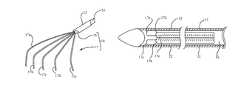
- FIGS. 1A-1Cshown is a minimally invasive surgical assembly 10 comprising a rake retractor 14 according to an illustrative embodiment of the present invention. More specifically, as will be further understood from the ensuing description, FIG. 1A is a schematic cross-sectional view of proximal and distal portions of surgical assembly 10 with rake retractor 14 in an extended position, and FIGS. 1B and 1C are side views of surgical assembly 10 with the retractor 14 in the retracted and extended positions, respectively.
- surgical assembly 10includes outer hollow needle 12 ; a grip 11 attached to a proximal portion of outer needle 12 and having a locking mechanism 13 ; rake retractor 14 comprising a shaft 16 that extends coaxially through the outer hollow needle 12 and retractor tines 17 at the distal end of the shaft; a handle 15 mechanically coupled to a proximal shaft 19 that is mechanically coupled to the proximal end of shaft 16 .
- retractor 14may be moved longitudinally (i.e., in the direction of the coaxial axis) relative to outer hollow needle 12 such that retractor tines 17 may be fully retracted within outer hollow needle 12 (e.g., as shown in FIG. 1B ) or partially or fully extended out of the outer hollow needle 12 (e.g., as shown in FIG. 1C ).
- locking mechanism 13may be used to selectively fix or secure retractor 14 relative to needle 12 .
- outer hollow needle 12is typically between 10 and 30 cm long, and more typically between 13 and 18 cm long (although other sizes could be used, depending upon the surgery involved, and typically larger for obese patients and smaller for infants and small children), and is made from stainless steel, although other materials could be used.
- needle 12has a sharpened distal end 18 which is angled at about 35° relative to a longitudinal axis of the needle, and has an outer diameter of about 2 mm (about 0.079 inches or 79 mils), an inner diameter of about 1.5 mm (about 0.060 inches or 60 mils), and a wall thickness of about 0.25 mm (about 0.010 inches or 10 mils).
- the outer diameter of 2 mmis sufficiently narrow such that a wound (e.g., puncture wound) formed by the needle does not require suturing or stitching, and upon healing will not result in a scar (or will not result in substantial or noticeable scarring).
- needle 12may be implemented with an outer diameter larger than 2 mm (e.g., 2.5 mm or 3.0 mm or larger) while still being sufficiently narrow such that a wound formed by the needle does not require suturing or stitching and/or upon healing will not result in scarring.
- needle 12 with a sufficiently narrow outer diameter and a sharpened tipalso allows for inserting surgical apparatus 10 into a patient (e.g., into the abdominal cavity) by using the needle to pierce or puncture the skin and fascia without first making an incision (e.g., a cutaneous incision), though the surgeon may still choose to make an initial incision through which the needle 12 will be inserted.
- a patiente.g., into the abdominal cavity
- an incisione.g., a cutaneous incision
- an outer needle or outer sleevee.g., which, in some embodiments, may not be configured as a needle, nor otherwise have a sharp or pointed tip
- needle 12may be alternatively implemented as an outer sleeve that does not have a sharp or pointed tip, regardless of the outer diameter of the outer sleeve.
- the embodiment of the rake retractor 14 shown in FIG. 1A , and further depicted in FIGS. 2A-2Dis a retractor type instrument having an elongated shaft 16 that is generally coaxial with the with outer needle 12 when inserted therein. As shown, in this embodiment, the proximal end of shaft 16 is mechanically coupled to a larger diameter proximal shaft 19 that is in turn mechanically coupled to a handle 15 .
- Each such mechanical couplingmay be provided in any of various common or different ways, such as by integral formation (e.g., by machining from a unitary component) or by fastening (e.g., by welding, epoxying, threading, etc.) the components directly to each other or to an intermediary coupling member. While retractor 14 includes a shaft 16 and tines 17 , in some embodiments proximal shaft 19 as well as handle 15 may be considered as being part of the retractor.
- the surgical assembly 10may be adapted such that the retractor 14 along with mechanically coupled shaft 19 and handle 15 may be entirely disengaged from, and selectively inserted by a surgeon into, needle 12 and grip 11 . Accordingly, the surgeon may insert the retractor 14 into grip 11 and needle 12 after inserting needle 12 into the patient. Additionally, the surgeon may, if desired, remove the retractor 14 and insert a different instrument into the same needle 12 that is already positioned in the patient.
- a guide mechanismsuch as a combination of one or more longitudinal slots and one or more complementary tabs or ridges or rails provided on shaft 19 and the inner bore of grip 11 , may be implemented such that retractor 14 has a fixed rotational (e.g., azimuthal) orientation about the longitudinal axis and relative to needle 12 as retractor 14 is moved along the longitudinal direction (e.g., between the fully retracted and fully extended positions).
- the rotational (azimuthal) orientation of the retractor relative to longitudinal axis of needle 12may be any one of two or more possible orientations that may be selected upon insertion of the retractor into the grip 11 and needle 12 (e.g., by aligning the complementary components of the guide mechanism in a desired orientation upon insertion).
- shaft 19may have two longitudinal slots displaced by 180° about the longitudinal axis, and either two rails (or two tabs) displaced by 180° about the longitudinal axis or one longitudinal rail (or a single tab) may be provided on the inner bore of grip 11 , thus allowing retractor 14 to be selectively oriented in one of two azimuthal orientations (displaced by 180°) relative to the longitudinal axis of the needle 12 .
- inner bore of grip 11 and proximal shaft 19may have a non-circular cross-sectional shape that permits orientation in only one or more discrete rotational orientations. For instance, a square cross section for shaft 19 and the inner bore of grip 11 would permit retractor 14 to be orientated in any one of four rotational positions about the longitudinal axis associated with needle 12 .
- such guidesmay provide for some limited range of rotation about the longitudinal axis (e.g., the circumferential width of the slot compared to the width of the tab or rail may allow for 30° or 45° rotation about the longitudinal axis).
- such guide mechanismsmay not be provided, or may be disengaged, such that the retractor 14 may be freely rotated by the surgeon about the longitudinal axis to manipulate and position the retractor at any desired azimuthal angle.
- the retractor 14 and needle 12are sized so that at least a portion of the shaft 16 of the retractor 14 interferingly slides against the inner surface of the needle 12 , thereby forming a seal which is effective against desufflation.
- the outer diameter of the shaft 16is approximately 1.49 mm (0.059 inches or 59 mils), or about 0.01 mm smaller than the inner diameter of the needle. This small difference in diameters results in a sliding interference fit which can be felt as a drag and which effectively acts as a seal against desufflation.
- the needlemay include an internal gasket or seal (e.g., an O-ring) that seals against the outer diameter of the shaft.
- a seal against desufflationmay additionally or alternatively be provided between at least a portion of shaft 19 and the inner bore of grip 11 .
- the distal end of retractor 14includes tines 17 , which, in this embodiment, have a curved, continuous arcuate shape.
- Tines 17i.e., comprising individual tines 17 a - e
- Tines 17are formed so that they are mechanically biased to an open position (as seen in FIGS. 1A and 1C , and FIGS. 2B and 2C ) such that they automatically open when the end effectors 22 of the surgical instrument 14 extend out of the needle 12 , and they close when the needle extends over them (as seen in FIG. 1B , and FIGS. 2A and 2D ).
- the tines 17are mechanically/elastically strained in the closed position (e.g., when disposed within the needle) and are under monotonically decreasing elastic strain as the tines 17 are increasingly extended out of the needle 12 (i.e., the mechanical strain decreases as the tines extend to their biased, relaxed position).
- the tines 17may be formed from the end of the shaft 16 , such as by machining or etching, or may be formed in any other desired manner, such as by separately forming individual tines 17 and connecting them (e.g., by welding) to the shaft.
- the combined length of shaft 16 and shaft 19 compared to the combined length of needle 12 and grip 11must be long enough to permit the tines 17 to extend out of the needle.
- the retractor 14is preferably made from stainless steel, although other materials could be used for all or part of the instrument 14 .
- tines 17when extended into the open position, fan out relative to one another, with the proximal portions of the tines being disposed approximately in a plane that is approximately parallel with the longitudinal axis, and with the distal end portion of each tine curving along a direction that is in a plane that intersects, and in this embodiment is approximately perpendicular to, the plane in which the proximal portions of the tines fan out.
- FIGS. 2A and 2Dwhen in the closed position, tines 17 are substantially straight and parallel, packed along and within the distal portion of needle 12 .
- the end portionsare blunt or rounded (to prevent or reduce the likelihood that the tines will inadvertently puncture tissue). Additionally, as depicted in FIG. 2D , in various embodiments, the ends of two or more tines in the closed position do not occupy a common plane that is substantially perpendicular to the longitudinal axis of needle 12 , although in various embodiments two or more tines may substantially occupy such a plane.
- This design feature of the end portions of the tinesmay be provided to achieve various design objectives; for example, the end portions not occupying a common plane substantially perpendicular to the longitudinal axis may result from the tines design being provided to ensure that when the tines open they each extend approximately the same distance in the longitudinal direction before curving, and the hooked or curved portion of each tine is substantially the same shape and length. As such, under these design parameters, tines that fan out to a greater extent will be longer (assuming all tines emanate from the shaft 16 at a common plane substantially perpendicular to the longitudinal axis). It is appreciated, however, that the tines need not extend the same distance longitudinally, nor need to have the same curvature or length of their distal portions.
- having at least two of the end portions not occupying a common plane substantially perpendicular to the longitudinal axismay also be well suited for allowing the tips or end portions of the tines to be wider than the width or diameter of the remainder of the tines (e.g., ball tips), while allowing the tines to fit within the needle 12 (i.e., by preventing the tips, e.g., ball-tips, from physically interfering with each other, viz., attempting to occupy the same space within the needs, when closed).
- FIG. 2Eis a schematic cross-sectional view of the distal end of surgical apparatus 10 with instrument 14 in the fully retracted position, viewed along the longitudinal axis associated with outer needle 12 and coaxial shaft 16 at a longitudinal position adjacent to and distal from the longitudinal position where retractor tines 17 a - e emanate from shaft 16 of retractor 14 , as indicated by reference lines III-III′ in FIG. 2A , in accordance with some embodiments of the present invention.
- retractor tines 17 a - ehave a generally equally sized circular cross-section (though they need not have equal sizes, nor must they have a uniform cross section along their length), and their respective center axes are disposed in an approximately pentagonal relationship, this pentagonal configuration providing essentially the most efficient circular cross-section tine packing within the circular inner cross-section of the needle, allowing each of the five equal-diameter tines to have essentially the largest equal diameter while fitting within the needle.
- FIGS. 3A-3Ddepict cross-sectional views of various illustrative alternative tine implementations having different numbers of tines and/or spatial configurations, though the tines in each of these configurations have a generally circular cross section. More specifically, FIG. 3A depicts five tines 31 spatially configured according to a generally hexagonal close-packed arrangement, which is the arrangement also implemented to provide six tines 33 and seven tines 35 in the configurations of FIGS. 3B and 3C , respectively. FIG. 3D depicts four tines 37 spatially configured according to a generally square arrangement.
- the tines 17 of retractor 14may be implemented in any of myriad configurations; for example, the number, shape, length, mechanical strength and elasticity or resiliency of the tines may be selected and designed to satisfy various uses or objectives (e.g., depending on type of surgery, type and size of tissue to be retracted, etc.). In such myriad configurations and variations, however, the tines are mechanically biased to an expanded position such that they automatically spread relative to each other when they are extended out of the needle.
- tines 47include ball-tips 49 .
- the ball tipsmay be provided to help prevent tissue damage.
- the ball endsmay also facilitate using the rake retractor to rake, scrape, or otherwise manipulate tissue or other particulates or materials.
- one of the tines emanating from shaft 16may be formed into a Y-shaped distal portion, which, in this embodiment, also includes a ball tip 49 on each end.
- FIG. 4Bschematically depicts the tines of FIG.
- a rake retractormay have tines 57 having spoon-like shaped ends 59 .
- Such a spoon-like shapemay assist scooping or scraping various types of tissue or particulates that may be encountered during various types of surgeries. Alternatively, these elements may be used by the surgeon to assist in the placement of desired surgical tools or pharmaceutical agents.
- the tines 57 in this embodimentmay be configured such that they are longitudinally displaced when in the closed position. Additionally, or alternatively, two or more of the spoon-like ends may be configured to spoon against each other when in the closed position.
- FIG. 4Dschematically illustrates a rake retractor according to another embodiment of the present invention, wherein tines 77 include angular bends 79 to provide a hooked configuration.
- tines 77are nevertheless substantially straight and substantially aligned along the longitudinal axis when the tines 77 are entirely within needle 12 in the closed position.
- each of one or more tines 87may include two or more angular bends 89 and 89 ′ to provide increased curvature or hooking, e.g., for greater scooping effect, which may be desired in various implementations.
- the tinesWhile in the embodiments discussed above, the tines have a curved, hooked, or bent shape, which may facilitate using retractor 14 to pull tissue structures, in some embodiments the tines may be substantially straight, substantially without curvature or bends, such as depicted in FIG. 4F .
- shaft 16may alternatively or additionally be adapted to provide a hooking or scooping effect.
- shaft 16 of the rake retractor(with tines 97 ) may include an angular bend 101 to provide a mechanical bias.
- FIG. 5Billustrates a further illustrative embodiment of a rake retractor (with tines 107 ) with angular bends 102 and 103 along shaft 16 .
- additional bendsmay be provided, and the distance between bends determined according to the implementation.
- the surgeonmay adjust the scooping effect by moving the shaft 16 relative to needle 12 longitudinally to selectively extend or retract one or more angular bends relative to the end of the needle.
- the shaft 16In the fully retracted position, the shaft 16 is substantially straight and substantially parallel to the longitudinal axis of the needle 12 , and the shaft is in a mechanically strained condition, which is relaxed as each of the one or more angular bends are extended external to the needle.
- shaft 16may alternatively or additionally be mechanically biased such that it has a continuous arcuate curvature along at least a portion thereof when in a mechanically relaxed state (e.g., when extended outside the needle).
- a surgical apparatus 10 comprising a rake retractor 14 in accordance with embodiments of the present inventionmay be used by a surgeon in accordance with the following illustrative method.
- the surgeonuses the needle 12 to puncture the skin and advance the needle portion of the surgical apparatus into the body (e.g., the abdomen).
- the rake retractor 14may be inserted into the needle 12 after the needle 12 is inserted into the patient.
- needle 12may be adapted to puncture the skin and penetrate the facia
- surgeonmay, if desired, nevertheless make an initial incision (e.g., cutaneous incision) into which the needle is inserted.
- initial incisione.g., cutaneous incision
- the movement of the needleis stopped.
- the rake retractor 14is then unlocked (if previously locked, e.g., by locking mechanism 13 and/or other locking mechanisms, such as a thumbscrew) and advanced relative to the needle 12 to extent the tines 17 beyond the distal end of needle 12 such that they automatically expand into the open position.
- the surgeonmay then lock the retractor 14 relative to needle 12 (e.g., using locking mechanism 13 F), and may further move the retractor and needle together to maneuver the tines of the rake retractor 14 to manipulate tissue or other objects within the patient (e.g., within the abdominal cavity).
- the surgeonmay selectively unlock locking mechanism 13 and adjust the relative position of shaft 16 relative to needle 12 as desired, and then relock locking mechanism 13 .
- the locking mechanism 13may be unlocked and the rake retractor 14 pulled proximally relative to the needle 12 such that the tines 17 are fully retracted into needle 12 .
- the locking mechanism 13may then be engaged (locked).
- the surgical apparatus 10may be withdrawn from the body typically, but not necessarily, with the rake retractor first withdrawn relative to the needle such that the tines are in the closed position within the needle.
- removal of the surgical instrument 10leaves a small puncture mark that will often heal without a scar. It is also noted that because of the small diameter of the surgical assembly according to various embodiments of the present invention, withdrawal of the needle assembly from the abdomen will not cause desufflation, and should not require stitching to close the wound.
- the surgical apparatus 10in accordance with various embodiments of the present invention includes a locking means that is used to fix the relative location of the rake retractor 14 relative to needle 12 .
- locking mechanism 13is provided as a cam element that is rotatingly coupled to the grip 11 by a pin 73 .
- the cam elementWhen in a first orientation, the cam element permits proximal shaft 19 , and thus shaft 16 of retractor instrument 14 to which proximal shaft 19 is mechanically coupled (e.g., fastened to or integrally formed with) r fastened to) to move in an uninhibited manner.
- the cam elementengages shaft 19 and holds shaft 19 , and hence retractor 14 , fixed relative to the grip 11 and needle 12 .
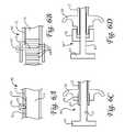
- FIGS. 6A-6Dschematically depict various illustrative locking mechanisms that may be additionally or alternatively implemented in accordance with some embodiments of the present invention. More specifically, in FIG. 6A , a fixing system 50 is shown to include notches 52 on at least a portion of the shaft 16 of the rake retractor instrument 14 , and a screw 54 which extends through a threaded radial hole 55 in the needle 12 or its grip 11 .
- the screw 54is screwed (typically clockwise) into the needle and into engagement with a notch 52 .
- the screw 54is unscrewed so that it is no longer engaged in the notch.
- FIG. 6Banother fixing system 50 ′ is shown to include radial grooves 60 on the shaft 16 of the rake retractor and a clip 61 having spring arms 62 (one shown), and a shaft 63 .
- the shaft 63 of the clip 61extends through a wall of the needle or, more preferably, its grip 11 , and the spring arms 62 engage a radial groove 64 on the shaft 16 (or shaft 19 ).
- the spring arms 62spread to permit movement of the shaft 16 past the clip 61 . It will be appreciated that if the spring arms 62 are sufficiently springy, grooves are not required on the shaft 15 of the needle as the spring arms 62 will firmly hold the shaft in position.
- FIG. 6CAnother illustrative fixing system 50 ′′ schematically depicted in FIG. 6C includes a plastic screw 65 which extends around the shaft 16 of the rake retractor 14 , and an inner thread 66 located on the grip 20 of the needle 12 .
- the screw 65is screwed into the threaded grip 20 of the needle 12 .
- the plastic screw 65 and the inner thread 66 of the grip 20 of the needle 12are sized to cause the plastic screw 65 to deform and tighten around the shaft 16 when the screw 65 is screwed into the thread 66 , thereby fixing the locations of the needle 12 and surgical instrument 14 relative to each other.
- the screw 65When it is desired to release the rake retractor 14 , the screw 65 is unscrewed sufficiently to permit movement of the surgical instrument relative to the needle.
- the screw 65may have a gripping member such as a head (not shown) to help the practitioner apply torque.
- FIG. 6Dschematically depicts yet another illustrative fixing system 50 ′′′ which includes a thumb screw 70 and a grip 20 of the needle 12 which includes a thread (not shown), and which is flexible or plastic.
- the thumb screw 70when screwed onto the grip 20 threads causes the grip portion to clamp down on the shaft 16 of the rake retractor 14 and lock the rake retractor relative to the needle.
- the grip 20 and handle 14are depicted as modified relative to the grip 11 and handle 15 of FIGS. 1A-C , and further that the shaft 16 in FIGS. 6C and 6D extends with a constant diameter from the needle 12 to the handle 15 whereas in FIGS.
- 1A-C shaft 16is mechanically coupled to handle 15 via a proximal shaft 19 of larger diameter.
- proximal shaft 19of larger diameter.
- rake retractors and surgical assembliesin accordance with alternative implementations of the present invention may use any of a variety of materials, tine designs and configurations, grips, handles, locking mechanisms, etc.
Landscapes
- Health & Medical Sciences (AREA)
- Life Sciences & Earth Sciences (AREA)
- Surgery (AREA)
- Heart & Thoracic Surgery (AREA)
- Engineering & Computer Science (AREA)
- Biomedical Technology (AREA)
- Nuclear Medicine, Radiotherapy & Molecular Imaging (AREA)
- Medical Informatics (AREA)
- Molecular Biology (AREA)
- Animal Behavior & Ethology (AREA)
- General Health & Medical Sciences (AREA)
- Public Health (AREA)
- Veterinary Medicine (AREA)
- Surgical Instruments (AREA)
Abstract
Description
Claims (15)
Priority Applications (1)
| Application Number | Priority Date | Filing Date | Title |
|---|---|---|---|
| US11/654,970US8313507B2 (en) | 2006-03-13 | 2007-01-18 | Minimally invasive rake retractor and method for using same |
Applications Claiming Priority (4)
| Application Number | Priority Date | Filing Date | Title |
|---|---|---|---|
| US78155606P | 2006-03-13 | 2006-03-13 | |
| US11/420,927US7766937B2 (en) | 2006-03-13 | 2006-05-30 | Minimally invasive surgical assembly and methods |
| US82891606P | 2006-10-10 | 2006-10-10 | |
| US11/654,970US8313507B2 (en) | 2006-03-13 | 2007-01-18 | Minimally invasive rake retractor and method for using same |
Related Parent Applications (1)
| Application Number | Title | Priority Date | Filing Date |
|---|---|---|---|
| US11/420,927Continuation-In-PartUS7766937B2 (en) | 2006-03-13 | 2006-05-30 | Minimally invasive surgical assembly and methods |
Publications (2)
| Publication Number | Publication Date |
|---|---|
| US20070213595A1 US20070213595A1 (en) | 2007-09-13 |
| US8313507B2true US8313507B2 (en) | 2012-11-20 |
Family
ID=47172914
Family Applications (1)
| Application Number | Title | Priority Date | Filing Date |
|---|---|---|---|
| US11/654,970Active2028-11-05US8313507B2 (en) | 2006-03-13 | 2007-01-18 | Minimally invasive rake retractor and method for using same |
Country Status (1)
| Country | Link |
|---|---|
| US (1) | US8313507B2 (en) |
Cited By (17)
| Publication number | Priority date | Publication date | Assignee | Title |
|---|---|---|---|---|
| US20140188249A1 (en)* | 2012-12-28 | 2014-07-03 | Cook Medical Technologies Llc | Ureteral endoluminal device |
| WO2015047886A1 (en) | 2013-09-18 | 2015-04-02 | Teleflex Medical Incorporated | Exchanger surgical access port assembly and methods of use |
| US9931114B2 (en) | 2010-09-10 | 2018-04-03 | Pivot Medical, Inc. | Method and apparatus for passing suture through tissue |
| US9936937B2 (en) | 2013-08-20 | 2018-04-10 | Brigham Young University | Surgical retractor |
| US10098631B2 (en) | 2010-09-10 | 2018-10-16 | Pivot Medical, Inc. | Method and apparatus for passing suture through tissue |
| US20180333299A1 (en)* | 2015-11-12 | 2018-11-22 | Mor Research Applications Ltd. | Instrument for extracting nucleus of eye lens during cataract surgery |
| US20190183478A1 (en)* | 2017-12-14 | 2019-06-20 | Covidien Lp | Laparoscopic tissue manipulation device |
| US10368907B2 (en) | 2014-07-15 | 2019-08-06 | Teleflex Medical Incorporated | Exchanger surgical access port and methods of use |
| US10390852B2 (en) | 2013-04-16 | 2019-08-27 | Teleflex Medical Incorporated | Minimally invasive surgical assembly and methods |
| US10405850B2 (en) | 2010-09-10 | 2019-09-10 | Pivot Medical, Inc. | Method and apparatus for passing suture through tissue |
| US10537347B2 (en) | 2013-04-16 | 2020-01-21 | Teleflex Medical Incorporated | Needlescopic instrument with reusable handle and detachable needle assembly |
| US10898177B2 (en) | 2011-03-14 | 2021-01-26 | Ethicon Llc | Collapsible anvil plate assemblies for circular surgical stapling devices |
| US11045191B2 (en) | 2016-04-01 | 2021-06-29 | Cilag Gmbh International | Method for operating a surgical stapling system |
| US11064997B2 (en) | 2016-04-01 | 2021-07-20 | Cilag Gmbh International | Surgical stapling instrument |
| US11284890B2 (en) | 2016-04-01 | 2022-03-29 | Cilag Gmbh International | Circular stapling system comprising an incisable tissue support |
| US11337694B2 (en) | 2016-04-01 | 2022-05-24 | Cilag Gmbh International | Surgical cutting and stapling end effector with anvil concentric drive member |
| US12419637B2 (en) | 2016-04-01 | 2025-09-23 | Cilag Gmbh International | Surgical stapling instrument |
Families Citing this family (9)
| Publication number | Priority date | Publication date | Assignee | Title |
|---|---|---|---|---|
| US7766937B2 (en) | 2006-03-13 | 2010-08-03 | Mini-Lap Technologies, Inc. | Minimally invasive surgical assembly and methods |
| US20070282170A1 (en)* | 2006-05-30 | 2007-12-06 | Sundaram Ravikumar | Rake Retractor and Needle Assembly for Minimally Invasive Surgical Applications |
| US9326757B2 (en)* | 2009-12-31 | 2016-05-03 | Teleflex Medical Incorporated | Surgical instruments for laparoscopic aspiration and retraction |
| US9736342B2 (en)* | 2012-10-19 | 2017-08-15 | Milwaukee Electric Tool Corporation | Visual inspection device |
| US10136881B2 (en) | 2014-02-11 | 2018-11-27 | Mayo Foundation For Medical Education And Research | Laparoscopic retractor devices |
| US20180042595A1 (en)* | 2016-08-09 | 2018-02-15 | Terumo Cardiovascular Systems Corporation | Valve rake and mount for surgical retractor |
| CN107510492A (en)* | 2016-08-24 | 2017-12-26 | 谢尚闹 | For cutting off the tissue retraction hook and tissue retraction rhampotheca part of breast tumor |
| US11471186B2 (en)* | 2018-06-27 | 2022-10-18 | Luiz Lanat Pedreira de Cerqueira Filho | Thin cannulas trocar and method |
| US11937796B2 (en)* | 2020-06-18 | 2024-03-26 | Boston Scientific Medical Device Limited | Tissue-spreader assembly |
Citations (86)
| Publication number | Priority date | Publication date | Assignee | Title |
|---|---|---|---|---|
| US3817251A (en) | 1972-10-04 | 1974-06-18 | H Hasson | Laparoscope cannula |
| US3844291A (en) | 1973-04-26 | 1974-10-29 | G Moen | Grip device |
| US3938527A (en) | 1973-07-04 | 1976-02-17 | Centre De Recherche Industrielle De Quebec | Instrument for laparoscopic tubal cauterization |
| US3967625A (en)* | 1973-07-30 | 1976-07-06 | In Bae Yoon | Device for sterilizing the human female or male by ligation |
| US4016881A (en) | 1973-07-04 | 1977-04-12 | Centre De Recherche Industrielle Du Quebec | Instrument for use in laparoscopic tubal cauterization |
| US4077412A (en) | 1974-12-13 | 1978-03-07 | Moossun Mohamed H | Stomach intubation and catheter placement system |
| US4174715A (en)* | 1977-03-28 | 1979-11-20 | Hasson Harrith M | Multi-pronged laparoscopy forceps |
| US4570642A (en) | 1983-09-23 | 1986-02-18 | Daig Corporation | Endocardial extendable screw-in lead |
| USD293470S (en) | 1985-03-14 | 1987-12-29 | Adler David T | Combined adjustable positioner and holder for surgical instruments |
| US5073169A (en) | 1990-10-02 | 1991-12-17 | Steve Raiken | Trocar support |
| US5100402A (en) | 1990-10-05 | 1992-03-31 | Megadyne Medical Products, Inc. | Electrosurgical laparoscopic cauterization electrode |
| US5147316A (en) | 1990-11-19 | 1992-09-15 | Castillenti Thomas A | Laparoscopic trocar with self-locking port sleeve |
| US5176697A (en) | 1989-04-06 | 1993-01-05 | Hasson Harrith M | Laparoscopic cannula |
| US5176643A (en) | 1991-04-29 | 1993-01-05 | George C. Kramer | System and method for rapid vascular drug delivery |
| US5201742A (en) | 1991-04-16 | 1993-04-13 | Hasson Harrith M | Support jig for a surgical instrument |
| US5222973A (en) | 1992-03-09 | 1993-06-29 | Sharpe Endosurgical Corporation | Endoscopic grasping tool surgical instrument |
| US5224954A (en) | 1991-02-19 | 1993-07-06 | Dexide, Inc. | Combination surgical trocar cannula and rake assembly |
| US5290276A (en) | 1992-02-06 | 1994-03-01 | Sewell Jr Frank | Rotatable laparoscopic puncturing instrument |
| US5330497A (en) | 1989-11-22 | 1994-07-19 | Dexide, Inc. | Locking trocar sleeve |
| US5342357A (en) | 1992-11-13 | 1994-08-30 | American Cardiac Ablation Co., Inc. | Fluid cooled electrosurgical cauterization system |
| US5354283A (en) | 1994-01-07 | 1994-10-11 | Little Rapids Corporation | Trocar retention apparatus |
| US5375588A (en) | 1992-08-17 | 1994-12-27 | Yoon; Inbae | Method and apparatus for use in endoscopic procedures |
| US5417697A (en) | 1993-07-07 | 1995-05-23 | Wilk; Peter J. | Polyp retrieval assembly with cauterization loop and suction web |
| US5425357A (en) | 1991-05-29 | 1995-06-20 | Origin Medsystems, Inc. | Inflatable retraction devices for use in laparoscopic surgery |
| US5439476A (en) | 1993-02-04 | 1995-08-08 | Trigonon, Inc. | Inflatable laparoscopic retractor |
| US5527264A (en) | 1991-05-29 | 1996-06-18 | Origin Medsystem, Inc. | Methods of using endoscopic inflatable retraction devices |
| US5556411A (en) | 1993-07-09 | 1996-09-17 | Nissho Corporation | Trocar assembly having a cannula retaining member |
| US5578030A (en) | 1994-11-04 | 1996-11-26 | Levin; John M. | Biopsy needle with cauterization feature |
| US5613937A (en) | 1993-02-22 | 1997-03-25 | Heartport, Inc. | Method of retracting heart tissue in closed-chest heart surgery using endo-scopic retraction |
| US5618306A (en) | 1994-02-14 | 1997-04-08 | Heartport, Inc. | Endoscopic microsurgical instruments and methods |
| US5626597A (en) | 1995-02-21 | 1997-05-06 | United States Surgical Corporation | Percutaneous introducer |
| US5634918A (en) | 1994-10-26 | 1997-06-03 | Grieshaber & Co. Ag Schaffhausen | Ophthalmic surgical instrument |
| US5658272A (en) | 1992-09-15 | 1997-08-19 | Hasson; Harrith M. | Surgical instrument support and method of using the same |
| USD388515S (en) | 1996-05-30 | 1997-12-30 | Flexbar Machine Corp. | Combined laparoscopic tool holder and positioner |
| USD389242S (en) | 1996-05-30 | 1998-01-13 | Flexbar Machine Corp. | Combined laphroscopic tool holder and positioner |
| USD389913S (en) | 1996-05-30 | 1998-01-27 | Flexbar Machine Corp. | Combined lap aroscopic tool holder and positioner |
| US5803902A (en) | 1994-10-06 | 1998-09-08 | United States Surgical Corporation | Surgical retractor |
| US5813976A (en) | 1996-04-02 | 1998-09-29 | Filipi; Charles J. | Stabilizing instrumentation for the performing of endoscopic surgical procedures |
| US5823945A (en) | 1991-05-29 | 1998-10-20 | Origin Medsystems, Inc. | Endoscopic inflatable retraction device with additional inflatable chamber |
| US5846191A (en) | 1996-09-13 | 1998-12-08 | Genzyme Corporation | Redo sternotomy retractor |
| US5857999A (en) | 1995-05-05 | 1999-01-12 | Imagyn Medical Technologies, Inc. | Small diameter introducer for laparoscopic instruments |
| US5871453A (en) | 1994-02-08 | 1999-02-16 | Boston Scientific Corporation | Moveable sample tube multiple biopsy sampling device |
| US5893873A (en) | 1995-10-23 | 1999-04-13 | Johns Hopkins University | Surgical instrument having a handle with a removable, rotatable tip |
| US5906620A (en) | 1995-06-29 | 1999-05-25 | Nakao; Naomi L. | Surgical cauterization snare with ligating suture |
| US5919163A (en) | 1997-07-14 | 1999-07-06 | Delcath Systems, Inc. | Catheter with slidable balloon |
| US5951574A (en) | 1998-10-23 | 1999-09-14 | Ethicon Endo-Surgery, Inc. | Multiple clip applier having a split feeding mechanism |
| US5951488A (en) | 1992-02-18 | 1999-09-14 | Symbiosis Corporation | Endoscopic multiple sample bioptome |
| USD426883S (en) | 1999-07-22 | 2000-06-20 | Surgiform Technology, Ltd. | Cauterization smoke evacuator |
| US6090042A (en) | 1998-01-23 | 2000-07-18 | Rullo; Janice Lee | Surgical support apparatus with adjustable rake and adjustable cable lifting disk |
| US6099550A (en) | 1989-12-05 | 2000-08-08 | Yoon; Inbae | Surgical instrument having jaws and an operating channel and method for use thereof |
| US6155439A (en) | 1999-02-22 | 2000-12-05 | Flexbar Machine Corp. | Laparoscopic-rack instruments holder |
| US6165184A (en) | 1996-11-18 | 2000-12-26 | Smith & Nephew, Inc. | Systems methods and instruments for minimally invasive surgery |
| US6190311B1 (en) | 1997-05-02 | 2001-02-20 | Cardiothoracic Systems, Inc. | Retractor and instrument platform for a less invasive cardiovascular surgical procedure |
| US6197002B1 (en) | 1997-12-10 | 2001-03-06 | Phillips Plastics Corporation | Laparoscopic tool and method |
| US6200263B1 (en) | 1998-01-23 | 2001-03-13 | United States Surgical Corporation | Surgical instrument holder |
| US6248062B1 (en) | 2000-11-09 | 2001-06-19 | Flexbar Machine Corp. | Laparoscopic retractor |
| US6258107B1 (en) | 1998-08-17 | 2001-07-10 | DEUTSCHES ZENTRUM FüR LUFT-UND RAUMFAHRT E.V. | Apparatus for connecting a variety of surgical instruments to an operating control device |
| US6319266B1 (en) | 2000-03-16 | 2001-11-20 | United States Surgical Corporation | Trocar system and method of use |
| US6322578B1 (en) | 1997-07-14 | 2001-11-27 | Heartport, Inc. | Endoscopic microsurgical instruments |
| US20010056286A1 (en) | 2000-10-19 | 2001-12-27 | Heinz Etter | Surgical instrument |
| US6391046B1 (en) | 2000-04-14 | 2002-05-21 | Duke University | Omni-actuatable hand-held surgical instruments |
| US6428503B1 (en) | 1999-01-19 | 2002-08-06 | Atc Technologies, Inc. | Surgical instrument for providing suction and irrigation |
| US6504985B2 (en) | 1995-06-27 | 2003-01-07 | Lumitex, Inc. | Illuminated surgical retractor |
| US20030040773A1 (en) | 2001-08-23 | 2003-02-27 | Arumi Jose Garcia | Micro surgical instrument |
| US20030050613A1 (en)* | 1997-12-17 | 2003-03-13 | Hammerslag Julius G. | Controlled viscosity dermal adhesive |
| US20030130693A1 (en)* | 1999-05-18 | 2003-07-10 | Levin John M. | Laparoscopic/thorascopic insertion caps |
| US20030145865A1 (en) | 1992-12-03 | 2003-08-07 | Sterman Wesley D. | Devices and methods for intracardiac procedures |
| US6616683B1 (en) | 2000-05-02 | 2003-09-09 | Duke University | Method of making miniaturized surgical forceps |
| US6630103B2 (en) | 2001-03-27 | 2003-10-07 | Crs Holding, Inc. | Ultra-high-strength precipitation-hardenable stainless steel and strip made therefrom |
| US6648839B2 (en) | 2002-02-28 | 2003-11-18 | Misonix, Incorporated | Ultrasonic medical treatment device for RF cauterization and related method |
| US6736814B2 (en) | 2002-02-28 | 2004-05-18 | Misonix, Incorporated | Ultrasonic medical treatment device for bipolar RF cauterization and related method |
| US6743237B2 (en) | 2001-01-17 | 2004-06-01 | Innon Holdings, Llc | Endoscopic stone extraction device with improved basket |
| US6761718B2 (en) | 2001-09-06 | 2004-07-13 | Children's Medical Center Corp. | Direction-oriented and spatially controlled bipolar coagulator for in-situ cauterization of adherent cranial tissue occluding a ventricular catheter previously implanted in-vivo |
| US6830578B2 (en) | 2001-11-26 | 2004-12-14 | Neosurg Technologies, Inc. | Trocar |
| US6832984B2 (en) | 1997-08-21 | 2004-12-21 | Paul Stelzer | Minimally invasive surgery device |
| US6860894B1 (en) | 2002-02-15 | 2005-03-01 | Gregory R. Pittman | Laparoscopic lifter apparatus and method |
| US20050113737A1 (en) | 1998-05-01 | 2005-05-26 | Mark Ashby | Device and method for facilitating hemostasis of a biopsy tract |
| US6908454B2 (en) | 2002-02-15 | 2005-06-21 | Taut, Inc. | Anchoring assembly for a medical instrument |
| US20050273133A1 (en) | 2003-08-26 | 2005-12-08 | Shluzas Alan E | Access systems and methods for minimally invasive surgery |
| US6989003B2 (en) | 2001-08-31 | 2006-01-24 | Conmed Corporation | Obturator and cannula for a trocar adapted for ease of insertion and removal |
| US7001333B2 (en) | 2000-12-20 | 2006-02-21 | Hamel Ross J | Surgical retractor system |
| US7041055B2 (en) | 2002-10-07 | 2006-05-09 | Mark LoGuidice | Instruments and methods for use in laparoscopic surgery |
| US7066879B2 (en) | 2003-07-15 | 2006-06-27 | The Trustees Of Columbia University In The City Of New York | Insertable device and system for minimal access procedure |
| US7112172B2 (en) | 2002-05-17 | 2006-09-26 | Tyco Healthcare Group Lp | Endoscopic organ retraction system and method of using the same |
| US7169156B2 (en)* | 1993-07-26 | 2007-01-30 | Innovasive Devices, Inc. | Suture grasping device |
| US7223267B2 (en) | 2004-02-06 | 2007-05-29 | Misonix, Incorporated | Ultrasonic probe with detachable slidable cauterization forceps |
Family Cites Families (1)
| Publication number | Priority date | Publication date | Assignee | Title |
|---|---|---|---|---|
| US3871251A (en)* | 1972-11-08 | 1975-03-18 | Fallon Investment Co O | Cutting tool for the continuous machining of metals and the method of making same |
- 2007
- 2007-01-18USUS11/654,970patent/US8313507B2/enactiveActive
Patent Citations (89)
| Publication number | Priority date | Publication date | Assignee | Title |
|---|---|---|---|---|
| US3817251A (en) | 1972-10-04 | 1974-06-18 | H Hasson | Laparoscope cannula |
| US3844291A (en) | 1973-04-26 | 1974-10-29 | G Moen | Grip device |
| US3938527A (en) | 1973-07-04 | 1976-02-17 | Centre De Recherche Industrielle De Quebec | Instrument for laparoscopic tubal cauterization |
| US4016881A (en) | 1973-07-04 | 1977-04-12 | Centre De Recherche Industrielle Du Quebec | Instrument for use in laparoscopic tubal cauterization |
| US3967625A (en)* | 1973-07-30 | 1976-07-06 | In Bae Yoon | Device for sterilizing the human female or male by ligation |
| US4077412A (en) | 1974-12-13 | 1978-03-07 | Moossun Mohamed H | Stomach intubation and catheter placement system |
| US4174715A (en)* | 1977-03-28 | 1979-11-20 | Hasson Harrith M | Multi-pronged laparoscopy forceps |
| US4570642A (en) | 1983-09-23 | 1986-02-18 | Daig Corporation | Endocardial extendable screw-in lead |
| USD293470S (en) | 1985-03-14 | 1987-12-29 | Adler David T | Combined adjustable positioner and holder for surgical instruments |
| US5176697A (en) | 1989-04-06 | 1993-01-05 | Hasson Harrith M | Laparoscopic cannula |
| US5330497A (en) | 1989-11-22 | 1994-07-19 | Dexide, Inc. | Locking trocar sleeve |
| US6099550A (en) | 1989-12-05 | 2000-08-08 | Yoon; Inbae | Surgical instrument having jaws and an operating channel and method for use thereof |
| US5073169A (en) | 1990-10-02 | 1991-12-17 | Steve Raiken | Trocar support |
| US5100402A (en) | 1990-10-05 | 1992-03-31 | Megadyne Medical Products, Inc. | Electrosurgical laparoscopic cauterization electrode |
| US5147316A (en) | 1990-11-19 | 1992-09-15 | Castillenti Thomas A | Laparoscopic trocar with self-locking port sleeve |
| US5224954A (en) | 1991-02-19 | 1993-07-06 | Dexide, Inc. | Combination surgical trocar cannula and rake assembly |
| US5201742A (en) | 1991-04-16 | 1993-04-13 | Hasson Harrith M | Support jig for a surgical instrument |
| US5176643A (en) | 1991-04-29 | 1993-01-05 | George C. Kramer | System and method for rapid vascular drug delivery |
| US5527264A (en) | 1991-05-29 | 1996-06-18 | Origin Medsystem, Inc. | Methods of using endoscopic inflatable retraction devices |
| US5823945A (en) | 1991-05-29 | 1998-10-20 | Origin Medsystems, Inc. | Endoscopic inflatable retraction device with additional inflatable chamber |
| US5425357A (en) | 1991-05-29 | 1995-06-20 | Origin Medsystems, Inc. | Inflatable retraction devices for use in laparoscopic surgery |
| US5290276A (en) | 1992-02-06 | 1994-03-01 | Sewell Jr Frank | Rotatable laparoscopic puncturing instrument |
| US5951488A (en) | 1992-02-18 | 1999-09-14 | Symbiosis Corporation | Endoscopic multiple sample bioptome |
| US5222973A (en) | 1992-03-09 | 1993-06-29 | Sharpe Endosurgical Corporation | Endoscopic grasping tool surgical instrument |
| US5375588A (en) | 1992-08-17 | 1994-12-27 | Yoon; Inbae | Method and apparatus for use in endoscopic procedures |
| US5658272A (en) | 1992-09-15 | 1997-08-19 | Hasson; Harrith M. | Surgical instrument support and method of using the same |
| US5342357A (en) | 1992-11-13 | 1994-08-30 | American Cardiac Ablation Co., Inc. | Fluid cooled electrosurgical cauterization system |
| US20030145865A1 (en) | 1992-12-03 | 2003-08-07 | Sterman Wesley D. | Devices and methods for intracardiac procedures |
| US5439476A (en) | 1993-02-04 | 1995-08-08 | Trigonon, Inc. | Inflatable laparoscopic retractor |
| US5613937A (en) | 1993-02-22 | 1997-03-25 | Heartport, Inc. | Method of retracting heart tissue in closed-chest heart surgery using endo-scopic retraction |
| US5417697A (en) | 1993-07-07 | 1995-05-23 | Wilk; Peter J. | Polyp retrieval assembly with cauterization loop and suction web |
| US5556411A (en) | 1993-07-09 | 1996-09-17 | Nissho Corporation | Trocar assembly having a cannula retaining member |
| US7169156B2 (en)* | 1993-07-26 | 2007-01-30 | Innovasive Devices, Inc. | Suture grasping device |
| US5354283A (en) | 1994-01-07 | 1994-10-11 | Little Rapids Corporation | Trocar retention apparatus |
| US5871453A (en) | 1994-02-08 | 1999-02-16 | Boston Scientific Corporation | Moveable sample tube multiple biopsy sampling device |
| US5618306A (en) | 1994-02-14 | 1997-04-08 | Heartport, Inc. | Endoscopic microsurgical instruments and methods |
| US5803902A (en) | 1994-10-06 | 1998-09-08 | United States Surgical Corporation | Surgical retractor |
| US5634918A (en) | 1994-10-26 | 1997-06-03 | Grieshaber & Co. Ag Schaffhausen | Ophthalmic surgical instrument |
| US5578030A (en) | 1994-11-04 | 1996-11-26 | Levin; John M. | Biopsy needle with cauterization feature |
| US5626597A (en) | 1995-02-21 | 1997-05-06 | United States Surgical Corporation | Percutaneous introducer |
| US5857999A (en) | 1995-05-05 | 1999-01-12 | Imagyn Medical Technologies, Inc. | Small diameter introducer for laparoscopic instruments |
| US6504985B2 (en) | 1995-06-27 | 2003-01-07 | Lumitex, Inc. | Illuminated surgical retractor |
| US5906620A (en) | 1995-06-29 | 1999-05-25 | Nakao; Naomi L. | Surgical cauterization snare with ligating suture |
| US5893873A (en) | 1995-10-23 | 1999-04-13 | Johns Hopkins University | Surgical instrument having a handle with a removable, rotatable tip |
| US5813976A (en) | 1996-04-02 | 1998-09-29 | Filipi; Charles J. | Stabilizing instrumentation for the performing of endoscopic surgical procedures |
| USD389913S (en) | 1996-05-30 | 1998-01-27 | Flexbar Machine Corp. | Combined lap aroscopic tool holder and positioner |
| USD389242S (en) | 1996-05-30 | 1998-01-13 | Flexbar Machine Corp. | Combined laphroscopic tool holder and positioner |
| USD388515S (en) | 1996-05-30 | 1997-12-30 | Flexbar Machine Corp. | Combined laparoscopic tool holder and positioner |
| US5846191A (en) | 1996-09-13 | 1998-12-08 | Genzyme Corporation | Redo sternotomy retractor |
| US6165184A (en) | 1996-11-18 | 2000-12-26 | Smith & Nephew, Inc. | Systems methods and instruments for minimally invasive surgery |
| US6190311B1 (en) | 1997-05-02 | 2001-02-20 | Cardiothoracic Systems, Inc. | Retractor and instrument platform for a less invasive cardiovascular surgical procedure |
| US5919163A (en) | 1997-07-14 | 1999-07-06 | Delcath Systems, Inc. | Catheter with slidable balloon |
| US6322578B1 (en) | 1997-07-14 | 2001-11-27 | Heartport, Inc. | Endoscopic microsurgical instruments |
| US6832984B2 (en) | 1997-08-21 | 2004-12-21 | Paul Stelzer | Minimally invasive surgery device |
| US6197002B1 (en) | 1997-12-10 | 2001-03-06 | Phillips Plastics Corporation | Laparoscopic tool and method |
| US20030050613A1 (en)* | 1997-12-17 | 2003-03-13 | Hammerslag Julius G. | Controlled viscosity dermal adhesive |
| US6200263B1 (en) | 1998-01-23 | 2001-03-13 | United States Surgical Corporation | Surgical instrument holder |
| US6610009B2 (en) | 1998-01-23 | 2003-08-26 | United States Surgical Corporation | Surgical instrument holder |
| US6090042A (en) | 1998-01-23 | 2000-07-18 | Rullo; Janice Lee | Surgical support apparatus with adjustable rake and adjustable cable lifting disk |
| US20050113737A1 (en) | 1998-05-01 | 2005-05-26 | Mark Ashby | Device and method for facilitating hemostasis of a biopsy tract |
| US6258107B1 (en) | 1998-08-17 | 2001-07-10 | DEUTSCHES ZENTRUM FüR LUFT-UND RAUMFAHRT E.V. | Apparatus for connecting a variety of surgical instruments to an operating control device |
| US5951574A (en) | 1998-10-23 | 1999-09-14 | Ethicon Endo-Surgery, Inc. | Multiple clip applier having a split feeding mechanism |
| US6428503B1 (en) | 1999-01-19 | 2002-08-06 | Atc Technologies, Inc. | Surgical instrument for providing suction and irrigation |
| US6155439A (en) | 1999-02-22 | 2000-12-05 | Flexbar Machine Corp. | Laparoscopic-rack instruments holder |
| US20030130693A1 (en)* | 1999-05-18 | 2003-07-10 | Levin John M. | Laparoscopic/thorascopic insertion caps |
| USD426883S (en) | 1999-07-22 | 2000-06-20 | Surgiform Technology, Ltd. | Cauterization smoke evacuator |
| US6319266B1 (en) | 2000-03-16 | 2001-11-20 | United States Surgical Corporation | Trocar system and method of use |
| US6391046B1 (en) | 2000-04-14 | 2002-05-21 | Duke University | Omni-actuatable hand-held surgical instruments |
| US6616683B1 (en) | 2000-05-02 | 2003-09-09 | Duke University | Method of making miniaturized surgical forceps |
| US20010056286A1 (en) | 2000-10-19 | 2001-12-27 | Heinz Etter | Surgical instrument |
| US6248062B1 (en) | 2000-11-09 | 2001-06-19 | Flexbar Machine Corp. | Laparoscopic retractor |
| US7001333B2 (en) | 2000-12-20 | 2006-02-21 | Hamel Ross J | Surgical retractor system |
| US6743237B2 (en) | 2001-01-17 | 2004-06-01 | Innon Holdings, Llc | Endoscopic stone extraction device with improved basket |
| US6630103B2 (en) | 2001-03-27 | 2003-10-07 | Crs Holding, Inc. | Ultra-high-strength precipitation-hardenable stainless steel and strip made therefrom |
| US20030040773A1 (en) | 2001-08-23 | 2003-02-27 | Arumi Jose Garcia | Micro surgical instrument |
| US6945984B2 (en) | 2001-08-23 | 2005-09-20 | Alcon Grieshaber Ag | Micro surgical instrument |
| US6989003B2 (en) | 2001-08-31 | 2006-01-24 | Conmed Corporation | Obturator and cannula for a trocar adapted for ease of insertion and removal |
| US6761718B2 (en) | 2001-09-06 | 2004-07-13 | Children's Medical Center Corp. | Direction-oriented and spatially controlled bipolar coagulator for in-situ cauterization of adherent cranial tissue occluding a ventricular catheter previously implanted in-vivo |
| US6830578B2 (en) | 2001-11-26 | 2004-12-14 | Neosurg Technologies, Inc. | Trocar |
| US6908454B2 (en) | 2002-02-15 | 2005-06-21 | Taut, Inc. | Anchoring assembly for a medical instrument |
| US6860894B1 (en) | 2002-02-15 | 2005-03-01 | Gregory R. Pittman | Laparoscopic lifter apparatus and method |
| US6902536B2 (en) | 2002-02-28 | 2005-06-07 | Milsonix Incorporated | Ultrasonic medical treatment device for RF cauterization and related method |
| US6736814B2 (en) | 2002-02-28 | 2004-05-18 | Misonix, Incorporated | Ultrasonic medical treatment device for bipolar RF cauterization and related method |
| US6648839B2 (en) | 2002-02-28 | 2003-11-18 | Misonix, Incorporated | Ultrasonic medical treatment device for RF cauterization and related method |
| US7112172B2 (en) | 2002-05-17 | 2006-09-26 | Tyco Healthcare Group Lp | Endoscopic organ retraction system and method of using the same |
| US7041055B2 (en) | 2002-10-07 | 2006-05-09 | Mark LoGuidice | Instruments and methods for use in laparoscopic surgery |
| US7066879B2 (en) | 2003-07-15 | 2006-06-27 | The Trustees Of Columbia University In The City Of New York | Insertable device and system for minimal access procedure |
| US20050273133A1 (en) | 2003-08-26 | 2005-12-08 | Shluzas Alan E | Access systems and methods for minimally invasive surgery |
| US7223267B2 (en) | 2004-02-06 | 2007-05-29 | Misonix, Incorporated | Ultrasonic probe with detachable slidable cauterization forceps |
Non-Patent Citations (1)
| Title |
|---|
| Cauterization, Wikipedia entry, Mar. 14, 2008 (4 pages). |
Cited By (36)
| Publication number | Priority date | Publication date | Assignee | Title |
|---|---|---|---|---|
| US11793507B2 (en) | 2010-09-10 | 2023-10-24 | Stryker Corporation | Method and apparatus for passing suture through tissue |
| US12201293B2 (en) | 2010-09-10 | 2025-01-21 | Stryker Corporation | Method and apparatus for passing suture through tissue |
| US10828023B2 (en) | 2010-09-10 | 2020-11-10 | Stryker Corporation | Method and apparatus for passing suture through tissue |
| US11259795B2 (en) | 2010-09-10 | 2022-03-01 | Stryker Corporation | Method and apparatus for passing suture through tissue |
| US9931114B2 (en) | 2010-09-10 | 2018-04-03 | Pivot Medical, Inc. | Method and apparatus for passing suture through tissue |
| US11207063B2 (en) | 2010-09-10 | 2021-12-28 | Stryker Corporation | Method and apparatus for passing suture through tissue |
| US10098631B2 (en) | 2010-09-10 | 2018-10-16 | Pivot Medical, Inc. | Method and apparatus for passing suture through tissue |
| US10123794B2 (en) | 2010-09-10 | 2018-11-13 | Pivot Medical, Inc. | Method and apparatus for passing suture through tissue |
| US12201292B2 (en) | 2010-09-10 | 2025-01-21 | Stryker Corporation | Method and apparatus for passing suture through tissue |
| US10405850B2 (en) | 2010-09-10 | 2019-09-10 | Pivot Medical, Inc. | Method and apparatus for passing suture through tissue |
| US11478238B2 (en) | 2011-03-14 | 2022-10-25 | Cilag Gmbh International | Anvil assemblies with collapsible frames for circular staplers |
| US11864747B2 (en) | 2011-03-14 | 2024-01-09 | Cilag Gmbh International | Anvil assemblies for circular staplers |
| US10898177B2 (en) | 2011-03-14 | 2021-01-26 | Ethicon Llc | Collapsible anvil plate assemblies for circular surgical stapling devices |
| US20170079818A1 (en)* | 2012-12-28 | 2017-03-23 | Cook Medical Technologies Llc | Ureteral endoluminal device |
| US9539127B2 (en)* | 2012-12-28 | 2017-01-10 | Cook Medical Technologies Llc | Ureteral endoluminal abrasion device |
| US20140188249A1 (en)* | 2012-12-28 | 2014-07-03 | Cook Medical Technologies Llc | Ureteral endoluminal device |
| US10390852B2 (en) | 2013-04-16 | 2019-08-27 | Teleflex Medical Incorporated | Minimally invasive surgical assembly and methods |
| US10537347B2 (en) | 2013-04-16 | 2020-01-21 | Teleflex Medical Incorporated | Needlescopic instrument with reusable handle and detachable needle assembly |
| US11627975B2 (en) | 2013-04-16 | 2023-04-18 | Teleflex Medical Incorporated | Needlescopic instrument with reusable handle and detachable needle assembly |
| US9936937B2 (en) | 2013-08-20 | 2018-04-10 | Brigham Young University | Surgical retractor |
| US10856901B2 (en) | 2013-09-18 | 2020-12-08 | Teleflex Medical Incorporated | Exchanger surgical access port assembly and methods of use |
| WO2015047886A1 (en) | 2013-09-18 | 2015-04-02 | Teleflex Medical Incorporated | Exchanger surgical access port assembly and methods of use |
| US10368907B2 (en) | 2014-07-15 | 2019-08-06 | Teleflex Medical Incorporated | Exchanger surgical access port and methods of use |
| US11627984B2 (en) | 2014-07-15 | 2023-04-18 | Teleflex Medical Incorporated | Exchanger surgical access port and methods of use |
| EP3682826A1 (en) | 2014-07-15 | 2020-07-22 | Teleflex Medical Incorporated | Locking mechanism for surgical access port |
| US10744032B2 (en)* | 2015-11-12 | 2020-08-18 | Mor Research Applications Ltd. | Instrument for extracting nucleus of eye lens during cataract surgery |
| US20180333299A1 (en)* | 2015-11-12 | 2018-11-22 | Mor Research Applications Ltd. | Instrument for extracting nucleus of eye lens during cataract surgery |
| US11766257B2 (en) | 2016-04-01 | 2023-09-26 | Cilag Gmbh International | Surgical instrument comprising a display |
| US11337694B2 (en) | 2016-04-01 | 2022-05-24 | Cilag Gmbh International | Surgical cutting and stapling end effector with anvil concentric drive member |
| US11284890B2 (en) | 2016-04-01 | 2022-03-29 | Cilag Gmbh International | Circular stapling system comprising an incisable tissue support |
| US11058421B2 (en) | 2016-04-01 | 2021-07-13 | Cilag Gmbh International | Modular surgical stapling system comprising a display |
| US11045191B2 (en) | 2016-04-01 | 2021-06-29 | Cilag Gmbh International | Method for operating a surgical stapling system |
| US11064997B2 (en) | 2016-04-01 | 2021-07-20 | Cilag Gmbh International | Surgical stapling instrument |
| US12419637B2 (en) | 2016-04-01 | 2025-09-23 | Cilag Gmbh International | Surgical stapling instrument |
| US10758219B2 (en)* | 2017-12-14 | 2020-09-01 | Covidien Lp | Laparoscopic tissue manipulation device |
| US20190183478A1 (en)* | 2017-12-14 | 2019-06-20 | Covidien Lp | Laparoscopic tissue manipulation device |
Also Published As
| Publication number | Publication date |
|---|---|
| US20070213595A1 (en) | 2007-09-13 |
Similar Documents
| Publication | Publication Date | Title |
|---|---|---|
| US8313507B2 (en) | Minimally invasive rake retractor and method for using same | |
| US7766937B2 (en) | Minimally invasive surgical assembly and methods | |
| US8133255B2 (en) | Minimally invasive surgical assembly and methods | |
| US9486238B2 (en) | Minimally invasive surgical clamps, assemblies and methods | |
| US11109875B2 (en) | Minimally invasive surgical assembly and methods | |
| US9861272B2 (en) | Apparatus, systems, and methods for performing laparoscopic surgery | |
| US9402613B2 (en) | Expandable thoracic access port | |
| US5415666A (en) | Tethered clamp retractor | |
| US5330501A (en) | Tissue gripping device for use with a cannula and a cannula incorporating the device | |
| US8795161B2 (en) | Button port | |
| US20050080434A1 (en) | Laparoscopic retractable dissector and suture and needle passer | |
| US8114053B2 (en) | Port fixation with interlocking structure | |
| US20070282170A1 (en) | Rake Retractor and Needle Assembly for Minimally Invasive Surgical Applications | |
| JP7083652B2 (en) | Surgical wound closure device | |
| US20140081329A1 (en) | Tissue anchor applicator | |
| JP2023149923A (en) | Endoscope treatment instrument |
Legal Events
| Date | Code | Title | Description |
|---|---|---|---|
| AS | Assignment | Owner name:MINI-LAP TECHNOLOGIES, INC., NEW YORK Free format text:ASSIGNMENT OF ASSIGNORS INTEREST;ASSIGNOR:RAVIKUMAR, SUNDARAM;REEL/FRAME:021979/0253 Effective date:20081215 | |
| STCF | Information on status: patent grant | Free format text:PATENTED CASE | |
| AS | Assignment | Owner name:TELEFLEX MEDICAL INCORPORATED, NORTH CAROLINA Free format text:ASSIGNMENT OF ASSIGNORS INTEREST;ASSIGNOR:MINI-LAP TECHNOLOGIES, INC.;REEL/FRAME:034426/0172 Effective date:20141202 | |
| FPAY | Fee payment | Year of fee payment:4 | |
| AS | Assignment | Owner name:JPMORGAN CHASE BANK, N.A., AS ADMINISTRATIVE AGENT, ILLINOIS Free format text:SECURITY INTEREST;ASSIGNOR:TELEFLEX MEDICAL INCORPORATED;REEL/FRAME:041761/0470 Effective date:20170217 Owner name:JPMORGAN CHASE BANK, N.A., AS ADMINISTRATIVE AGENT Free format text:SECURITY INTEREST;ASSIGNOR:TELEFLEX MEDICAL INCORPORATED;REEL/FRAME:041761/0470 Effective date:20170217 | |
| AS | Assignment | Owner name:JPMORGAN CHASE BANK, N.A., AS ADMINISTRATIVE AGENT Free format text:SECURITY INTEREST;ASSIGNOR:TELEFLEX MEDICAL INCORPORATED;REEL/FRAME:050620/0904 Effective date:20190925 Owner name:JPMORGAN CHASE BANK, N.A., AS ADMINISTRATIVE AGENT, ILLINOIS Free format text:SECURITY INTEREST;ASSIGNOR:TELEFLEX MEDICAL INCORPORATED;REEL/FRAME:050620/0904 Effective date:20190925 | |
| FEPP | Fee payment procedure | Free format text:ENTITY STATUS SET TO UNDISCOUNTED (ORIGINAL EVENT CODE: BIG.); ENTITY STATUS OF PATENT OWNER: LARGE ENTITY | |
| MAFP | Maintenance fee payment | Free format text:PAYMENT OF MAINTENANCE FEE, 8TH YEAR, LARGE ENTITY (ORIGINAL EVENT CODE: M1552); ENTITY STATUS OF PATENT OWNER: LARGE ENTITY Year of fee payment:8 | |
| MAFP | Maintenance fee payment | Free format text:PAYMENT OF MAINTENANCE FEE, 12TH YEAR, LARGE ENTITY (ORIGINAL EVENT CODE: M1553); ENTITY STATUS OF PATENT OWNER: LARGE ENTITY Year of fee payment:12 |