US8313490B2 - Single plane anatomic referencing tissue preparation - Google Patents
Single plane anatomic referencing tissue preparationDownload PDFInfo
- Publication number
- US8313490B2 US8313490B2US11/687,161US68716107AUS8313490B2US 8313490 B2US8313490 B2US 8313490B2US 68716107 AUS68716107 AUS 68716107AUS 8313490 B2US8313490 B2US 8313490B2
- Authority
- US
- United States
- Prior art keywords
- guide
- track
- handpiece
- surgical instrument
- anatomical structure
- Prior art date
- Legal status (The legal status is an assumption and is not a legal conclusion. Google has not performed a legal analysis and makes no representation as to the accuracy of the status listed.)
- Active, expires
Links
- 238000002360preparation methodMethods0.000titleclaims2
- 210000003484anatomyAnatomy0.000claimsabstract12
- 238000000034methodMethods0.000claims6
- 238000003801millingMethods0.000claims1
- XLYOFNOQVPJJNP-UHFFFAOYSA-NwaterSubstancesOXLYOFNOQVPJJNP-UHFFFAOYSA-N0.000claims1
- 210000000988bone and boneAnatomy0.000abstract1
- 210000000845cartilageAnatomy0.000abstract1
- 239000007943implantSubstances0.000abstract1
Images
Classifications
- A—HUMAN NECESSITIES
- A61—MEDICAL OR VETERINARY SCIENCE; HYGIENE
- A61B—DIAGNOSIS; SURGERY; IDENTIFICATION
- A61B17/00—Surgical instruments, devices or methods
- A61B17/16—Instruments for performing osteoclasis; Drills or chisels for bones; Trepans
- A61B17/17—Guides or aligning means for drills, mills, pins or wires
- A—HUMAN NECESSITIES
- A61—MEDICAL OR VETERINARY SCIENCE; HYGIENE
- A61B—DIAGNOSIS; SURGERY; IDENTIFICATION
- A61B17/00—Surgical instruments, devices or methods
- A61B17/16—Instruments for performing osteoclasis; Drills or chisels for bones; Trepans
- A61B2017/1602—Mills
- A—HUMAN NECESSITIES
- A61—MEDICAL OR VETERINARY SCIENCE; HYGIENE
- A61B—DIAGNOSIS; SURGERY; IDENTIFICATION
- A61B90/00—Instruments, implements or accessories specially adapted for surgery or diagnosis and not covered by any of the groups A61B1/00 - A61B50/00, e.g. for luxation treatment or for protecting wound edges
- A61B90/03—Automatic limiting or abutting means, e.g. for safety
- A61B2090/033—Abutting means, stops, e.g. abutting on tissue or skin
- A61B2090/034—Abutting means, stops, e.g. abutting on tissue or skin abutting on parts of the device itself
- A—HUMAN NECESSITIES
- A61—MEDICAL OR VETERINARY SCIENCE; HYGIENE
- A61B—DIAGNOSIS; SURGERY; IDENTIFICATION
- A61B34/00—Computer-aided surgery; Manipulators or robots specially adapted for use in surgery
- A61B34/20—Surgical navigation systems; Devices for tracking or guiding surgical instruments, e.g. for frameless stereotaxis
Definitions
- the present inventionrelates to surgical guides utilized for preparing a surface of an anatomical structure, such as a bone or cartilage, for example, to receive an orthopaedic implant. More particularly, the present invention relates to a system for preparing a surface of an anatomical structure to receive an orthopaedic implant using a guide which facilitates preparation of the anatomical surface in two dimensions.
- Implantation procedures for orthopaedic implantstypically require a surface of an anatomical structure to be prepared to receive the orthopaedic implant. Such surface preparation is typically done with highly accurate techniques.
- the present inventionprovides a system for preparing a surface of an anatomical structure, such as a bone or cartilage, for example, to receive an orthopaedic implant.
- the systemincludes a surgical instrument for preparing the surface and a guide engageable with a follower of the surgical instrument.
- the guideincludes a track or path configured to guide the follower and prepare a desired surface on the anatomical structure.
- the guidefacilitates guidance of the surgical instrument in two dimensions.
- the present inventionprovides a system for preparing a surface of an anatomical structure, including a surgical instrument, the surgical instrument including a follower; and a guide connected to the anatomical structure and engageable with the follower, the guide comprising a track configured to guide the follower in two dimensions when the follower is engaged with the guide.
- the present inventionprovides a system for preparing a surface of an anatomical structure, including a surgical instrument; and guide means for guiding the surgical instrument in two dimensions.
- the present inventionprovides a method for preparing a surface of an anatomical structure in two dimensions, including the steps of providing a guide having a track; engaging a follower of a surgical instrument with the track; and guiding preparation of the surface in two dimensions by moving the follower in the track.
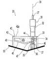
- FIG. 1is a perspective view of a system according to one embodiment of the present invention
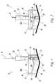
- FIG. 2is another perspective view of the system of FIG. 1 ;
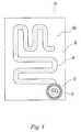
- FIG. 3is a top view of the system of FIG. 1 ;
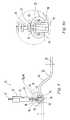
- FIG. 4is a perspective view of a system according to another embodiment, further illustrating a secondary guide.
- FIG. 4 ais a close-up view of a portion of the system of FIG. 4 .
- Surgical instrument 30generally may include first portion or handpiece 32 , rotary shaft 37 , follower 35 , and burr 36 .
- surgical instrument 30is illustrated as a milling instrument, any other suitable surgical instrument may also be utilized with system 20 , such as a laser instrument, an ultrasonic instrument, an abrasive water jet instrument, a radiofrequency cautery instrument, an oscillating instrument, or a reciprocating instrument, for example.
- Surgical instrument 30may be used to prepare anatomical structure 50 via any suitable process, such as morselizing bone, abrading cartilage, preparing tissue for bone cement, or removing tissue, for example.
- Guide 40generally may include top portion 42 , guide channel 44 in top portion 42 , bottom portion 46 , and guide channel 47 in bottom portion 46 .
- Guide 40may be attached to anatomical structure 50 via supports 48 in any suitable manner.
- Handpiece 32 of surgical instrument 30includes interconnection section 33 which extends through top portion 42 of guide 40 via channel 44 .
- Handpiece 32further includes guidance structure 34 connected to section 33 .
- guidance structure 34abuts surface 42 b of top portion 42 and handpiece 32 abuts surface 42 a of top portion 42 .
- the length of section 33is substantially equal to the thickness of top portion 42 defined between surfaces 42 a and 42 b and the width of section 33 is substantially equal to the width of channel 44 .
- handpiece 32 of surgical instrument 30is axially constrained relative to anatomical structure 50 when section 33 is engaged with channel 44 . Furthermore, due to the close abutment between handpiece 32 and surface 42 a as well as guidance structure 34 and surface 42 b , toggle between surgical instrument 30 and guide 40 is substantially eliminated and accuracy is thereby increased.
- Rotary shaft 37includes follower 35 and burr 36 axially fixed thereon.
- Rotary shaft 37extends through handpiece 32 and is connected to a rotation-imparting tool (not shown).
- Rotary shaft 37 and handpiece 32are joined together via a slip joint (not shown) within handpiece 32 .
- the slip jointprovides a rotational linkage, such as a key and keyway configuration, for example, between rotary shaft 37 and handpiece 32 .
- the slip jointallows rotary shaft 37 to vertically translate and move in two dimensions as dictated by bottom portion 46 of guide 40 , as described below, while handpiece 32 remains constrained to a single plane of movement by top portion 42 of guide 40 .
- follower 35may be formed of an inert and high temperature polyaryletherketone (“PAEK”) polymer material, such as polyetheretherketone (“PEEK”), for example.
- PAEKpolyaryletherketone
- bottom portion 46 of guide 40substantially matches the shape of a desired surface on anatomical structure 50 .
- bottom portion 46may be shaped with two generally planar faces with an oblique angle therebetween, as shown in FIGS. 1 and 2 .
- Bottom portion 46may, however, be formed in any other form, such as a contoured and/or curved shape as well as planar surfaces with multiple facets.
- Bottom portion 46includes guide channel 47 formed therein.
- Guide channel 47substantially matches the pattern of guide channel 44 , described below.
- Bottom portion 46defines a track or path for guiding movement of follower 35 of surgical instrument 30 in two dimensions.
- bottom portion 46defines an undulating track.
- such an undulating trackeliminates the need for a surgeon or user of instrument 30 to replicate the undulating movement required for preparation of anatomical structure 50 , as described below.
- top portion 42 of guide 40is illustrated and includes guide channel 44 formed therein.
- Guide channel 44extends through the thickness of top portion 42 from surface 42 a to surface 42 b ( FIGS. 1 and 2 ).
- Guide channel 44may be formed in any desired shape or pattern depending on the desired surface on anatomical structure 50 .
- guide channel 44may be a mobile guidance structure, i.e., top portion 42 of guide 40 may be laterally movable relative to anatomical structure 50 with guidance provided by supports 48 to keep top portion 42 in the single plane of movement.
- a surgeongrasps surgical instrument 30 at handpiece 32 .
- Rotary shaft 37is connected to the rotation-imparting tool (not shown) to supply rotational motion to burr 36 to effect a milling operation.
- the surgeoninserts surgical instrument 30 into guide 40 by moving section 33 into guide channel 44 in top portion 42 and by moving follower 35 into guide channel 47 in bottom portion 46 .
- the surgeonthen moves handpiece 32 through a pattern of movement dictated by guide channel 44 in a single plane of movement defined by top portion 42 of guide 40 .
- Guide channel 47matches the pattern of guide channel 44 , and, thus, follower 35 also follows the pattern of movement dictated by guide channel 44 .
- Bottom portion 46 of guide 40tracks the shape of bottom portion 46 of guide 40 in two dimensions for preparing anatomical structure 50 .
- bottom portion 46is shaped with two generally planar faces with an oblique angle therebetween.
- the planar faces of bottom portion 46define the undulating surface to be prepared on anatomical structure 50 .
- follower 35moves or tracks along bottom portion 46 and, consequently, burr 36 follows the same track or path as the shape of bottom portion 46 and removes a portion of anatomical structure 50 to obtain a finish surface on structure 50 which substantially matches the shape of bottom portion 46 .
- the surgeonmay select guide 40 to have any desired shape of bottom portion 46 which will be replicated on anatomical structure 50 , while simultaneously only requiring movement of handpiece 32 in the single plane of movement.
- the surgeonis not required to move handpiece 32 up and down relative to anatomical structure 50 to obtain the finish surface on anatomical structure 50 , but, instead the surgeon is required to simply move handpiece 32 in a single plane of movement and follower 35 of surgical instrument 30 tracks bottom portion 46 to dictate the resultant outcome on anatomical structure 50 .
- Burr 36is axially nondisplaceable relative to follower 35 .
- follower 35follows guide channel 47 , burr 36 travels in an identical pattern and direction.
- Central axis 39 of rotary shaft 37is shown as perpendicular to surface 42 a of top portion 42 of guide 40 .
- central axis 39may form an oblique angle with surface 42 a or be positioned normal to surface 42 a in operation, depending on the surgical environment and/or to facilitate a minimally invasive surgical procedure.
- system 20 ′includes surgical instrument 30 ′ and a guide (not shown) similar to guide 40 , described above with reference to FIGS. 1-3 .
- Surgical instrument 30 ′is substantially similar and includes the same general components as surgical instrument 30 , described above with reference to FIGS. 1-3 , except as described below.
- Surgical instrument 30 ′may include secondary guide 60 with distal ends 64 and proximal ends 62 .
- distalis meant to indicate a portion of the instrument farthest away from a user and the term “proximal” is meant to indicate a portion of the instrument closest to a user.
- Proximal ends 62 of secondary guide 60may be positioned in grooves or recesses 38 formed in rotary shaft 37 .
- Recesses 38may be formed in shaft 37 at predetermined intervals, such as at 1 millimeter (mm) increments, for example. A surgeon may then selectively locate the position of secondary guide 60 on shaft 37 to predetermine the depth of alteration performed by burr 36 , as described below.
- secondary guide 60is axially constrained along shaft 37 due to the engagement of proximal ends 62 and recesses 38 but is rotationally independent of rotary shaft 37 .
- Secondary guide 60may be formed of a material substantially similar to follower 35 , described above with reference to FIGS. 1 and 2 .
- secondary guide 60facilitates constant referencing of anatomical structure 50 . Furthermore, secondary guide 60 facilitates a repositioning and shaping of a given anatomical feature on anatomical structure 50 . For example, as burr 36 encounters a raised feature on anatomical structure 50 , burr 36 initially removes more tissue until burr 36 transitions past the peak of the raised feature after which burr 36 removes less tissue on the downward side of the raised feature. This procedure not only prepares a surface on anatomical structure 50 , but the location of the raised feature may be slightly translated, such as for restoring a proper patellar groove angle on a distal femur, for example.
- a surgeonmoves surgical instrument 30 ′ in substantially the same manner as described above with reference to the surgical procedure described with respect to FIGS. 1-3 .
- At least one distal end 64 of secondary guide 60rides on an unprepared surface of anatomical structure 50 .
- Burr 36extends past secondary guide 60 a distance “x”, which is equal to the amount of bone, cartilage, or other tissue to be removed from anatomical structure 50 .
- secondary guide 60may be displaced along rotary shaft 37 by the surgeon to set a predetermined value of “x”.
- Distal ends 64allow constant active referencing of unfinished surface 52 of anatomical structure 50 because at least one distal end 64 is always touching unfinished surface 52 .
- the predetermined amount of tissue removal defined by depth “x”may aid in manufacturing an implant to replace the removed tissue, such as manufacturing a linear thickness cartilage implant/substitute or a flexible hydrophilic polymeric sheet, for example.
- guide 40may be positioned on anatomical structure 50 and/or surgical instrument 30 may be operated with the assistance of a computer assisted surgery (CAS) system.
- CAScomputer assisted surgery
- a navigation apparatus of the CAS systemmay be used to accurately position guide 40 and/or operate surgical instrument 30 by using active or passive tracking, such as optical tracking, electromagnetic tracking, fluoroscopy, radiofrequency tracking, or a coordinate measurement machine, for example.
Landscapes
- Health & Medical Sciences (AREA)
- Surgery (AREA)
- Life Sciences & Earth Sciences (AREA)
- Biomedical Technology (AREA)
- Medical Informatics (AREA)
- Orthopedic Medicine & Surgery (AREA)
- Oral & Maxillofacial Surgery (AREA)
- Engineering & Computer Science (AREA)
- Dentistry (AREA)
- Heart & Thoracic Surgery (AREA)
- Nuclear Medicine, Radiotherapy & Molecular Imaging (AREA)
- Molecular Biology (AREA)
- Animal Behavior & Ethology (AREA)
- General Health & Medical Sciences (AREA)
- Public Health (AREA)
- Veterinary Medicine (AREA)
- Surgical Instruments (AREA)
Abstract
Description
Claims (21)
Priority Applications (1)
| Application Number | Priority Date | Filing Date | Title |
|---|---|---|---|
| US11/687,161US8313490B2 (en) | 2007-03-16 | 2007-03-16 | Single plane anatomic referencing tissue preparation |
Applications Claiming Priority (1)
| Application Number | Priority Date | Filing Date | Title |
|---|---|---|---|
| US11/687,161US8313490B2 (en) | 2007-03-16 | 2007-03-16 | Single plane anatomic referencing tissue preparation |
Publications (2)
| Publication Number | Publication Date |
|---|---|
| US20080234683A1 US20080234683A1 (en) | 2008-09-25 |
| US8313490B2true US8313490B2 (en) | 2012-11-20 |
Family
ID=39775482
Family Applications (1)
| Application Number | Title | Priority Date | Filing Date |
|---|---|---|---|
| US11/687,161Active2029-10-27US8313490B2 (en) | 2007-03-16 | 2007-03-16 | Single plane anatomic referencing tissue preparation |
Country Status (1)
| Country | Link |
|---|---|
| US (1) | US8313490B2 (en) |
Cited By (2)
| Publication number | Priority date | Publication date | Assignee | Title |
|---|---|---|---|---|
| US9579216B2 (en)* | 2013-03-08 | 2017-02-28 | Stryker Corporation | Bone pads |
| WO2019056248A1 (en)* | 2017-09-21 | 2019-03-28 | Zimmer, Inc. | Waterjet cutting system |
Families Citing this family (83)
| Publication number | Priority date | Publication date | Assignee | Title |
|---|---|---|---|---|
| US8298237B2 (en) | 2006-06-09 | 2012-10-30 | Biomet Manufacturing Corp. | Patient-specific alignment guide for multiple incisions |
| US9113971B2 (en) | 2006-02-27 | 2015-08-25 | Biomet Manufacturing, Llc | Femoral acetabular impingement guide |
| US8608748B2 (en) | 2006-02-27 | 2013-12-17 | Biomet Manufacturing, Llc | Patient specific guides |
| US8603180B2 (en) | 2006-02-27 | 2013-12-10 | Biomet Manufacturing, Llc | Patient-specific acetabular alignment guides |
| US8133234B2 (en) | 2006-02-27 | 2012-03-13 | Biomet Manufacturing Corp. | Patient specific acetabular guide and method |
| US9173661B2 (en) | 2006-02-27 | 2015-11-03 | Biomet Manufacturing, Llc | Patient specific alignment guide with cutting surface and laser indicator |
| US8858561B2 (en) | 2006-06-09 | 2014-10-14 | Blomet Manufacturing, LLC | Patient-specific alignment guide |
| US8070752B2 (en) | 2006-02-27 | 2011-12-06 | Biomet Manufacturing Corp. | Patient specific alignment guide and inter-operative adjustment |
| US8535387B2 (en) | 2006-02-27 | 2013-09-17 | Biomet Manufacturing, Llc | Patient-specific tools and implants |
| US8407067B2 (en) | 2007-04-17 | 2013-03-26 | Biomet Manufacturing Corp. | Method and apparatus for manufacturing an implant |
| US8864769B2 (en) | 2006-02-27 | 2014-10-21 | Biomet Manufacturing, Llc | Alignment guides with patient-specific anchoring elements |
| US9339278B2 (en) | 2006-02-27 | 2016-05-17 | Biomet Manufacturing, Llc | Patient-specific acetabular guides and associated instruments |
| US7967868B2 (en) | 2007-04-17 | 2011-06-28 | Biomet Manufacturing Corp. | Patient-modified implant and associated method |
| US8591516B2 (en) | 2006-02-27 | 2013-11-26 | Biomet Manufacturing, Llc | Patient-specific orthopedic instruments |
| US9345548B2 (en) | 2006-02-27 | 2016-05-24 | Biomet Manufacturing, Llc | Patient-specific pre-operative planning |
| US10278711B2 (en) | 2006-02-27 | 2019-05-07 | Biomet Manufacturing, Llc | Patient-specific femoral guide |
| US9289253B2 (en) | 2006-02-27 | 2016-03-22 | Biomet Manufacturing, Llc | Patient-specific shoulder guide |
| US20150335438A1 (en) | 2006-02-27 | 2015-11-26 | Biomet Manufacturing, Llc. | Patient-specific augments |
| US8092465B2 (en) | 2006-06-09 | 2012-01-10 | Biomet Manufacturing Corp. | Patient specific knee alignment guide and associated method |
| US8608749B2 (en) | 2006-02-27 | 2013-12-17 | Biomet Manufacturing, Llc | Patient-specific acetabular guides and associated instruments |
| US8241293B2 (en) | 2006-02-27 | 2012-08-14 | Biomet Manufacturing Corp. | Patient specific high tibia osteotomy |
| US8377066B2 (en) | 2006-02-27 | 2013-02-19 | Biomet Manufacturing Corp. | Patient-specific elbow guides and associated methods |
| US8473305B2 (en) | 2007-04-17 | 2013-06-25 | Biomet Manufacturing Corp. | Method and apparatus for manufacturing an implant |
| US9907659B2 (en) | 2007-04-17 | 2018-03-06 | Biomet Manufacturing, Llc | Method and apparatus for manufacturing an implant |
| US8282646B2 (en) | 2006-02-27 | 2012-10-09 | Biomet Manufacturing Corp. | Patient specific knee alignment guide and associated method |
| US8568487B2 (en) | 2006-02-27 | 2013-10-29 | Biomet Manufacturing, Llc | Patient-specific hip joint devices |
| US9918740B2 (en) | 2006-02-27 | 2018-03-20 | Biomet Manufacturing, Llc | Backup surgical instrument system and method |
| US9795399B2 (en) | 2006-06-09 | 2017-10-24 | Biomet Manufacturing, Llc | Patient-specific knee alignment guide and associated method |
| US8313490B2 (en)* | 2007-03-16 | 2012-11-20 | Zimmer Technology, Inc. | Single plane anatomic referencing tissue preparation |
| US7794462B2 (en)* | 2007-03-19 | 2010-09-14 | Zimmer Technology, Inc. | Handpiece calibration device |
| US8265949B2 (en) | 2007-09-27 | 2012-09-11 | Depuy Products, Inc. | Customized patient surgical plan |
| EP2194889B1 (en) | 2007-09-30 | 2015-09-23 | DePuy Products, Inc. | Customized patient-specific orthopaedic surgical instrumentation |
| US8357111B2 (en) | 2007-09-30 | 2013-01-22 | Depuy Products, Inc. | Method and system for designing patient-specific orthopaedic surgical instruments |
| US8562608B2 (en)* | 2008-09-19 | 2013-10-22 | Zimmer, Inc. | Patello-femoral milling system |
| US8170641B2 (en) | 2009-02-20 | 2012-05-01 | Biomet Manufacturing Corp. | Method of imaging an extremity of a patient |
| DE102009028503B4 (en) | 2009-08-13 | 2013-11-14 | Biomet Manufacturing Corp. | Resection template for the resection of bones, method for producing such a resection template and operation set for performing knee joint surgery |
| CA2778057C (en) | 2009-10-29 | 2019-02-19 | Zimmer, Inc. | Patient-specific mill guide |
| US8632547B2 (en) | 2010-02-26 | 2014-01-21 | Biomet Sports Medicine, Llc | Patient-specific osteotomy devices and methods |
| US9066727B2 (en) | 2010-03-04 | 2015-06-30 | Materialise Nv | Patient-specific computed tomography guides |
| US9271744B2 (en) | 2010-09-29 | 2016-03-01 | Biomet Manufacturing, Llc | Patient-specific guide for partial acetabular socket replacement |
| US9968376B2 (en) | 2010-11-29 | 2018-05-15 | Biomet Manufacturing, Llc | Patient-specific orthopedic instruments |
| US9241745B2 (en) | 2011-03-07 | 2016-01-26 | Biomet Manufacturing, Llc | Patient-specific femoral version guide |
| US8715289B2 (en) | 2011-04-15 | 2014-05-06 | Biomet Manufacturing, Llc | Patient-specific numerically controlled instrument |
| US9675400B2 (en) | 2011-04-19 | 2017-06-13 | Biomet Manufacturing, Llc | Patient-specific fracture fixation instrumentation and method |
| US8668700B2 (en) | 2011-04-29 | 2014-03-11 | Biomet Manufacturing, Llc | Patient-specific convertible guides |
| US8956364B2 (en) | 2011-04-29 | 2015-02-17 | Biomet Manufacturing, Llc | Patient-specific partial knee guides and other instruments |
| US8532807B2 (en) | 2011-06-06 | 2013-09-10 | Biomet Manufacturing, Llc | Pre-operative planning and manufacturing method for orthopedic procedure |
| US9084618B2 (en) | 2011-06-13 | 2015-07-21 | Biomet Manufacturing, Llc | Drill guides for confirming alignment of patient-specific alignment guides |
| US8764760B2 (en) | 2011-07-01 | 2014-07-01 | Biomet Manufacturing, Llc | Patient-specific bone-cutting guidance instruments and methods |
| US20130001121A1 (en) | 2011-07-01 | 2013-01-03 | Biomet Manufacturing Corp. | Backup kit for a patient-specific arthroplasty kit assembly |
| US8597365B2 (en) | 2011-08-04 | 2013-12-03 | Biomet Manufacturing, Llc | Patient-specific pelvic implants for acetabular reconstruction |
| US9066734B2 (en) | 2011-08-31 | 2015-06-30 | Biomet Manufacturing, Llc | Patient-specific sacroiliac guides and associated methods |
| US9295497B2 (en) | 2011-08-31 | 2016-03-29 | Biomet Manufacturing, Llc | Patient-specific sacroiliac and pedicle guides |
| US9386993B2 (en) | 2011-09-29 | 2016-07-12 | Biomet Manufacturing, Llc | Patient-specific femoroacetabular impingement instruments and methods |
| KR20130046337A (en) | 2011-10-27 | 2013-05-07 | 삼성전자주식회사 | Multi-view device and contol method thereof, display apparatus and contol method thereof, and display system |
| US9554910B2 (en) | 2011-10-27 | 2017-01-31 | Biomet Manufacturing, Llc | Patient-specific glenoid guide and implants |
| WO2013062848A1 (en) | 2011-10-27 | 2013-05-02 | Biomet Manufacturing Corporation | Patient-specific glenoid guides |
| US9301812B2 (en) | 2011-10-27 | 2016-04-05 | Biomet Manufacturing, Llc | Methods for patient-specific shoulder arthroplasty |
| US9451973B2 (en) | 2011-10-27 | 2016-09-27 | Biomet Manufacturing, Llc | Patient specific glenoid guide |
| US9237950B2 (en) | 2012-02-02 | 2016-01-19 | Biomet Manufacturing, Llc | Implant with patient-specific porous structure |
| US9204977B2 (en) | 2012-12-11 | 2015-12-08 | Biomet Manufacturing, Llc | Patient-specific acetabular guide for anterior approach |
| US9060788B2 (en) | 2012-12-11 | 2015-06-23 | Biomet Manufacturing, Llc | Patient-specific acetabular guide for anterior approach |
| US9839438B2 (en) | 2013-03-11 | 2017-12-12 | Biomet Manufacturing, Llc | Patient-specific glenoid guide with a reusable guide holder |
| US9579107B2 (en) | 2013-03-12 | 2017-02-28 | Biomet Manufacturing, Llc | Multi-point fit for patient specific guide |
| US9826981B2 (en) | 2013-03-13 | 2017-11-28 | Biomet Manufacturing, Llc | Tangential fit of patient-specific guides |
| US9498233B2 (en) | 2013-03-13 | 2016-11-22 | Biomet Manufacturing, Llc. | Universal acetabular guide and associated hardware |
| US9517145B2 (en) | 2013-03-15 | 2016-12-13 | Biomet Manufacturing, Llc | Guide alignment system and method |
| US20150112349A1 (en) | 2013-10-21 | 2015-04-23 | Biomet Manufacturing, Llc | Ligament Guide Registration |
| US10282488B2 (en) | 2014-04-25 | 2019-05-07 | Biomet Manufacturing, Llc | HTO guide with optional guided ACL/PCL tunnels |
| US9408616B2 (en) | 2014-05-12 | 2016-08-09 | Biomet Manufacturing, Llc | Humeral cut guide |
| US9561040B2 (en) | 2014-06-03 | 2017-02-07 | Biomet Manufacturing, Llc | Patient-specific glenoid depth control |
| US9839436B2 (en) | 2014-06-03 | 2017-12-12 | Biomet Manufacturing, Llc | Patient-specific glenoid depth control |
| US9826994B2 (en) | 2014-09-29 | 2017-11-28 | Biomet Manufacturing, Llc | Adjustable glenoid pin insertion guide |
| US9833245B2 (en) | 2014-09-29 | 2017-12-05 | Biomet Sports Medicine, Llc | Tibial tubercule osteotomy |
| US9820868B2 (en) | 2015-03-30 | 2017-11-21 | Biomet Manufacturing, Llc | Method and apparatus for a pin apparatus |
| US10226262B2 (en) | 2015-06-25 | 2019-03-12 | Biomet Manufacturing, Llc | Patient-specific humeral guide designs |
| US10568647B2 (en) | 2015-06-25 | 2020-02-25 | Biomet Manufacturing, Llc | Patient-specific humeral guide designs |
| US9999428B2 (en)* | 2015-06-30 | 2018-06-19 | DePuy Synthes Products, Inc. | Orthopaedic surgical instrument system and method for surgically preparing a patients bone |
| GB201514534D0 (en)* | 2015-08-14 | 2015-09-30 | Imp Innovations Ltd | Surgical tool guide |
| EP3235453A1 (en)* | 2016-04-20 | 2017-10-25 | Universität Basel | Bone processing guiding rail, arrangement comprising at least one first bone processing guiding rail and method for providing rail sections of a multipart bone tool guiding rail |
| US10722310B2 (en) | 2017-03-13 | 2020-07-28 | Zimmer Biomet CMF and Thoracic, LLC | Virtual surgery planning system and method |
| US11051829B2 (en) | 2018-06-26 | 2021-07-06 | DePuy Synthes Products, Inc. | Customized patient-specific orthopaedic surgical instrument |
| CN220546314U (en)* | 2023-03-29 | 2024-03-01 | 上海交通大学医学院附属第九人民医院 | Osteotomy guiding structure |
Citations (20)
| Publication number | Priority date | Publication date | Assignee | Title |
|---|---|---|---|---|
| US4457307A (en)* | 1982-08-20 | 1984-07-03 | Stillwell William T | Bone cutting device for total knee replacement |
| US5474559A (en)* | 1993-07-06 | 1995-12-12 | Zimmer, Inc. | Femoral milling instrumentation for use in total knee arthroplasty with optional cutting guide attachment |
| US5486180A (en)* | 1992-02-06 | 1996-01-23 | Zimmer, Inc. | Apparatus for milling bone |
| US5653714A (en)* | 1996-02-22 | 1997-08-05 | Zimmer, Inc. | Dual slide cutting guide |
| US5709689A (en)* | 1995-09-25 | 1998-01-20 | Wright Medical Technology, Inc. | Distal femur multiple resection guide |
| US5908424A (en)* | 1994-05-16 | 1999-06-01 | Zimmer, Inc, By Said Stalcup, Dietz, Bays And Vanlaningham | Tibial milling guide system |
| US6056754A (en)* | 1994-09-02 | 2000-05-02 | Hudson Surgical Design, Inc. | Method and apparatus for patella resection and guide handle |
| US6554838B2 (en)* | 2001-05-31 | 2003-04-29 | Howmedica Osteonics Corp. | Method and apparatus for implanting a prosthetic device |
| US6575980B1 (en)* | 1997-01-28 | 2003-06-10 | New York Society For The Ruptured And Crippled Maintaining The Hospital For Special Surgery | Method and apparatus for femoral resection |
| US6966731B2 (en)* | 2003-03-03 | 2005-11-22 | Tri Tool Inc. | Cutting tool and track guidance system |
| US20060293682A1 (en)* | 2005-06-10 | 2006-12-28 | Medicinelodge, Inc. | Milling system with guide paths and related methods for resecting a joint articulation surface |
| US7255702B2 (en)* | 2002-05-09 | 2007-08-14 | Serra Michael A | Bone milling instrument |
| US20080234683A1 (en)* | 2007-03-16 | 2008-09-25 | Zimmer Technology, Inc. | Single plane anatomic referencing tissue preparation |
| US20080234664A1 (en) | 2007-03-19 | 2008-09-25 | Zimmer Technology, Inc. | Handpiece calibration device |
| US7462199B2 (en)* | 2003-12-30 | 2008-12-09 | Medicinelodge, Inc. | Methods for mounting a tibial condylar implant |
| US7481814B1 (en)* | 2003-07-28 | 2009-01-27 | Biomet Manufacturing Corporation | Method and apparatus for use of a mill or reamer |
| US7488324B1 (en)* | 2003-12-08 | 2009-02-10 | Biomet Manufacturing Corporation | Femoral guide for implanting a femoral knee prosthesis |
| US7510557B1 (en)* | 2000-01-14 | 2009-03-31 | Bonutti Research Inc. | Cutting guide |
| US7766913B2 (en)* | 2004-12-07 | 2010-08-03 | Depuy Products, Inc. | Bone shaping instrument and method for using the same |
| US8052687B2 (en)* | 2006-09-29 | 2011-11-08 | Depuy Products, Inc. | Calcar planar |
- 2007
- 2007-03-16USUS11/687,161patent/US8313490B2/enactiveActive
Patent Citations (22)
| Publication number | Priority date | Publication date | Assignee | Title |
|---|---|---|---|---|
| US4457307A (en)* | 1982-08-20 | 1984-07-03 | Stillwell William T | Bone cutting device for total knee replacement |
| US5486180A (en)* | 1992-02-06 | 1996-01-23 | Zimmer, Inc. | Apparatus for milling bone |
| US5474559A (en)* | 1993-07-06 | 1995-12-12 | Zimmer, Inc. | Femoral milling instrumentation for use in total knee arthroplasty with optional cutting guide attachment |
| US5908424A (en)* | 1994-05-16 | 1999-06-01 | Zimmer, Inc, By Said Stalcup, Dietz, Bays And Vanlaningham | Tibial milling guide system |
| US6056754A (en)* | 1994-09-02 | 2000-05-02 | Hudson Surgical Design, Inc. | Method and apparatus for patella resection and guide handle |
| US5709689A (en)* | 1995-09-25 | 1998-01-20 | Wright Medical Technology, Inc. | Distal femur multiple resection guide |
| US5653714A (en)* | 1996-02-22 | 1997-08-05 | Zimmer, Inc. | Dual slide cutting guide |
| US6575980B1 (en)* | 1997-01-28 | 2003-06-10 | New York Society For The Ruptured And Crippled Maintaining The Hospital For Special Surgery | Method and apparatus for femoral resection |
| US7615054B1 (en)* | 2000-01-14 | 2009-11-10 | Martec, LLC | Bicompartmental knee implant and method |
| US7510557B1 (en)* | 2000-01-14 | 2009-03-31 | Bonutti Research Inc. | Cutting guide |
| US6554838B2 (en)* | 2001-05-31 | 2003-04-29 | Howmedica Osteonics Corp. | Method and apparatus for implanting a prosthetic device |
| US7255702B2 (en)* | 2002-05-09 | 2007-08-14 | Serra Michael A | Bone milling instrument |
| US6966731B2 (en)* | 2003-03-03 | 2005-11-22 | Tri Tool Inc. | Cutting tool and track guidance system |
| US7481814B1 (en)* | 2003-07-28 | 2009-01-27 | Biomet Manufacturing Corporation | Method and apparatus for use of a mill or reamer |
| US7488324B1 (en)* | 2003-12-08 | 2009-02-10 | Biomet Manufacturing Corporation | Femoral guide for implanting a femoral knee prosthesis |
| US7462199B2 (en)* | 2003-12-30 | 2008-12-09 | Medicinelodge, Inc. | Methods for mounting a tibial condylar implant |
| US7766913B2 (en)* | 2004-12-07 | 2010-08-03 | Depuy Products, Inc. | Bone shaping instrument and method for using the same |
| US20060293682A1 (en)* | 2005-06-10 | 2006-12-28 | Medicinelodge, Inc. | Milling system with guide paths and related methods for resecting a joint articulation surface |
| US8052687B2 (en)* | 2006-09-29 | 2011-11-08 | Depuy Products, Inc. | Calcar planar |
| US20080234683A1 (en)* | 2007-03-16 | 2008-09-25 | Zimmer Technology, Inc. | Single plane anatomic referencing tissue preparation |
| US20080234664A1 (en) | 2007-03-19 | 2008-09-25 | Zimmer Technology, Inc. | Handpiece calibration device |
| US7794462B2 (en)* | 2007-03-19 | 2010-09-14 | Zimmer Technology, Inc. | Handpiece calibration device |
Cited By (6)
| Publication number | Priority date | Publication date | Assignee | Title |
|---|---|---|---|---|
| US9579216B2 (en)* | 2013-03-08 | 2017-02-28 | Stryker Corporation | Bone pads |
| US9937059B2 (en) | 2013-03-08 | 2018-04-10 | Stryker Corporation | Bone pads |
| US10537441B2 (en)* | 2013-03-08 | 2020-01-21 | Stryker Corporation | Bone pads |
| US11318027B2 (en)* | 2013-03-08 | 2022-05-03 | Stryker Corporation | Bone pads |
| WO2019056248A1 (en)* | 2017-09-21 | 2019-03-28 | Zimmer, Inc. | Waterjet cutting system |
| US11648015B2 (en) | 2017-09-21 | 2023-05-16 | Zimmer, Inc. | Waterjet cutting system |
Also Published As
| Publication number | Publication date |
|---|---|
| US20080234683A1 (en) | 2008-09-25 |
Similar Documents
| Publication | Publication Date | Title |
|---|---|---|
| US8313490B2 (en) | Single plane anatomic referencing tissue preparation | |
| US11849957B2 (en) | Patient-specific instrumentation and method for articular joint repair | |
| US12053186B2 (en) | Spring-fit surgical guides | |
| US9700325B2 (en) | Multi-point fit for patient specific guide | |
| US7374563B2 (en) | Apparatus and method for guiding a surgical instrument for shaping the end of a bone | |
| EP3229722B1 (en) | Implant based planning, digitizing, and registration for total joint arthroplasty | |
| US20120323246A1 (en) | Patient-Specific Partial Knee Guides And Other Instruments | |
| EP3469997A2 (en) | Method for forming a mold | |
| EP2685915B1 (en) | Guide tool for resection of patellofemoral joint | |
| US20070055269A1 (en) | Implants, instruments and procedure for a unicompartmental knee replacement | |
| US20150088142A1 (en) | Patient specific instrument | |
| WO2011041398A1 (en) | Patient-specific alignment guide with cutting surface and laser indicator | |
| US11648015B2 (en) | Waterjet cutting system | |
| EP4543322A1 (en) | Surgical sagittal blade cartridge |
Legal Events
| Date | Code | Title | Description |
|---|---|---|---|
| AS | Assignment | Owner name:ZIMMER TECHNOLOGY, INC., INDIANA Free format text:ASSIGNMENT OF ASSIGNORS INTEREST;ASSIGNOR:MAY, JUSTIN J.;REEL/FRAME:019023/0940 Effective date:20070314 | |
| FEPP | Fee payment procedure | Free format text:PAYOR NUMBER ASSIGNED (ORIGINAL EVENT CODE: ASPN); ENTITY STATUS OF PATENT OWNER: LARGE ENTITY | |
| STCF | Information on status: patent grant | Free format text:PATENTED CASE | |
| AS | Assignment | Owner name:ZIMMER, INC., INDIANA Free format text:MERGER;ASSIGNOR:ZIMMER TECHNOLOGY, INC.;REEL/FRAME:029698/0017 Effective date:20121127 | |
| FPAY | Fee payment | Year of fee payment:4 | |
| MAFP | Maintenance fee payment | Free format text:PAYMENT OF MAINTENANCE FEE, 8TH YEAR, LARGE ENTITY (ORIGINAL EVENT CODE: M1552); ENTITY STATUS OF PATENT OWNER: LARGE ENTITY Year of fee payment:8 | |
| MAFP | Maintenance fee payment | Free format text:PAYMENT OF MAINTENANCE FEE, 12TH YEAR, LARGE ENTITY (ORIGINAL EVENT CODE: M1553); ENTITY STATUS OF PATENT OWNER: LARGE ENTITY Year of fee payment:12 |