US8313308B2 - Medical infusion pump with closed loop stroke feedback system and method - Google Patents
Medical infusion pump with closed loop stroke feedback system and methodDownload PDFInfo
- Publication number
- US8313308B2 US8313308B2US10/810,123US81012304AUS8313308B2US 8313308 B2US8313308 B2US 8313308B2US 81012304 AUS81012304 AUS 81012304AUS 8313308 B2US8313308 B2US 8313308B2
- Authority
- US
- United States
- Prior art keywords
- stroke
- pumping chamber
- plunger
- pump
- volume
- Prior art date
- Legal status (The legal status is an assumption and is not a legal conclusion. Google has not performed a legal analysis and makes no representation as to the accuracy of the status listed.)
- Expired - Lifetime, expires
Links
Images


Classifications
- A—HUMAN NECESSITIES
- A61—MEDICAL OR VETERINARY SCIENCE; HYGIENE
- A61M—DEVICES FOR INTRODUCING MEDIA INTO, OR ONTO, THE BODY; DEVICES FOR TRANSDUCING BODY MEDIA OR FOR TAKING MEDIA FROM THE BODY; DEVICES FOR PRODUCING OR ENDING SLEEP OR STUPOR
- A61M5/00—Devices for bringing media into the body in a subcutaneous, intra-vascular or intramuscular way; Accessories therefor, e.g. filling or cleaning devices, arm-rests
- A61M5/14—Infusion devices, e.g. infusing by gravity; Blood infusion; Accessories therefor
- A61M5/142—Pressure infusion, e.g. using pumps
- A61M5/14212—Pumping with an aspiration and an expulsion action
- A61M5/14224—Diaphragm type
- A—HUMAN NECESSITIES
- A61—MEDICAL OR VETERINARY SCIENCE; HYGIENE
- A61M—DEVICES FOR INTRODUCING MEDIA INTO, OR ONTO, THE BODY; DEVICES FOR TRANSDUCING BODY MEDIA OR FOR TAKING MEDIA FROM THE BODY; DEVICES FOR PRODUCING OR ENDING SLEEP OR STUPOR
- A61M5/00—Devices for bringing media into the body in a subcutaneous, intra-vascular or intramuscular way; Accessories therefor, e.g. filling or cleaning devices, arm-rests
- A61M5/14—Infusion devices, e.g. infusing by gravity; Blood infusion; Accessories therefor
- A61M5/168—Means for controlling media flow to the body or for metering media to the body, e.g. drip meters, counters ; Monitoring media flow to the body
- A61M5/16804—Flow controllers
- A61M5/16809—Flow controllers by repeated filling and emptying of an intermediate volume
- A—HUMAN NECESSITIES
- A61—MEDICAL OR VETERINARY SCIENCE; HYGIENE
- A61M—DEVICES FOR INTRODUCING MEDIA INTO, OR ONTO, THE BODY; DEVICES FOR TRANSDUCING BODY MEDIA OR FOR TAKING MEDIA FROM THE BODY; DEVICES FOR PRODUCING OR ENDING SLEEP OR STUPOR
- A61M5/00—Devices for bringing media into the body in a subcutaneous, intra-vascular or intramuscular way; Accessories therefor, e.g. filling or cleaning devices, arm-rests
- A61M5/14—Infusion devices, e.g. infusing by gravity; Blood infusion; Accessories therefor
- A61M5/168—Means for controlling media flow to the body or for metering media to the body, e.g. drip meters, counters ; Monitoring media flow to the body
- A61M5/172—Means for controlling media flow to the body or for metering media to the body, e.g. drip meters, counters ; Monitoring media flow to the body electrical or electronic
- A—HUMAN NECESSITIES
- A61—MEDICAL OR VETERINARY SCIENCE; HYGIENE
- A61M—DEVICES FOR INTRODUCING MEDIA INTO, OR ONTO, THE BODY; DEVICES FOR TRANSDUCING BODY MEDIA OR FOR TAKING MEDIA FROM THE BODY; DEVICES FOR PRODUCING OR ENDING SLEEP OR STUPOR
- A61M2205/00—General characteristics of the apparatus
- A61M2205/12—General characteristics of the apparatus with interchangeable cassettes forming partially or totally the fluid circuit
- A61M2205/128—General characteristics of the apparatus with interchangeable cassettes forming partially or totally the fluid circuit with incorporated valves
- A—HUMAN NECESSITIES
- A61—MEDICAL OR VETERINARY SCIENCE; HYGIENE
- A61M—DEVICES FOR INTRODUCING MEDIA INTO, OR ONTO, THE BODY; DEVICES FOR TRANSDUCING BODY MEDIA OR FOR TAKING MEDIA FROM THE BODY; DEVICES FOR PRODUCING OR ENDING SLEEP OR STUPOR
- A61M2205/00—General characteristics of the apparatus
- A61M2205/33—Controlling, regulating or measuring
- A61M2205/3331—Pressure; Flow
- A—HUMAN NECESSITIES
- A61—MEDICAL OR VETERINARY SCIENCE; HYGIENE
- A61M—DEVICES FOR INTRODUCING MEDIA INTO, OR ONTO, THE BODY; DEVICES FOR TRANSDUCING BODY MEDIA OR FOR TAKING MEDIA FROM THE BODY; DEVICES FOR PRODUCING OR ENDING SLEEP OR STUPOR
- A61M5/00—Devices for bringing media into the body in a subcutaneous, intra-vascular or intramuscular way; Accessories therefor, e.g. filling or cleaning devices, arm-rests
- A61M5/14—Infusion devices, e.g. infusing by gravity; Blood infusion; Accessories therefor
- A61M5/168—Means for controlling media flow to the body or for metering media to the body, e.g. drip meters, counters ; Monitoring media flow to the body
- A61M5/16831—Monitoring, detecting, signalling or eliminating infusion flow anomalies
- A61M5/16854—Monitoring, detecting, signalling or eliminating infusion flow anomalies by monitoring line pressure
Definitions
- the present inventionrelates to a means of determining and controlling the operating condition of a medical pump. More particularly, this invention relates to a means of adjusting a stroke frequency of a pump to compensate for individual variation in the stroke volume delivered by the medical pump.
- Modern medical careoften involves the use of medical pump devices to deliver fluids and/or fluid medicine to patients.
- Medical pumpspermit the controlled delivery of fluids to a patient, and such pumps have largely replaced gravity flow systems, primarily due to the pump's much greater accuracy in delivery rates and dosages, and due to the possibility for flexible yet controlled delivery schedules.
- those incorporating a diaphragmare often preferred because they provide a more accurate controlled rate and volume than do other types of pumps.
- a typical positive displacement pump systemincludes a pump device driver and a disposable fluid or pumping chamber, defined in various forms including but not limited to a cassette, syringe barrel or section of tubing.
- a disposable cassettewhich is adapted to be used only for a single patient and for one fluid delivery cycle, is typically a small plastic unit having an inlet and an outlet respectively connected through flexible tubing to the fluid supply container and to the patient receiving the fluid.
- the cassetteincludes a pumping chamber, with the flow of fluid through the chamber being controlled by a plunger or pumping element activated in a controlled manner by the device driver.
- the cassette chambermay have one wall formed by a flexible diaphragm that is reciprocated by the plunger and the driver to cause fluid to flow.
- the pump driver deviceincludes the plunger or pumping element for controlling the flow of fluid into and out of the pumping chamber in the cassette, and it also includes control mechanisms to assure that the fluid is delivered to the patient at a pre-set rate, in a pre-determined manner, and only for a particular pre-selected time or total dosage.
- the fluidenters the cassette through an inlet and is forced through an outlet under pressure.
- the fluidis delivered to the outlet when the pump plunger forces the membrane into the pumping chamber to displace the fluid.
- the pump plungerdraws back, the membrane covering the pumping chamber pulls back from its prior fully displaced configuration, and the fluid is then drawn through the open inlet and into the pumping chamber.
- the pump plungerforces the membrane back into the pumping chamber to force the fluid contained therein through the outlet.
- the fluidflows from the cassette in a series of spaced-apart pulses rather than in a continuous flow.
- One of the requirements for a medical pumpis that it is able to deliver precise volumes at precise delivery rates.
- Conventional pumpsin general, rely on nominal or empirical data to estimate the delivery volumes and delivery rates, and do not provide mechanisms for adjusting an actual delivery due to variations from this nominal or empirical data. This lack of adjustment during an actual delivery limits the accuracy of these pumps.
- a medical pump with a closed loop stroke feedback system and method, for use with a fluid chamber or pumping chamberis disclosed.
- the fluid or pumping chambercan be included in or defined by a cassette, syringe barrel, or section of tubing.
- the pumpincludes a pumping element that intermittently pressurizes the pumping chamber during a pumping cycle.
- a pressure sensordetects the pressure exerted by the pumping element on the pumping chamber.
- a position sensordetects the position of the pumping element.
- a processing unitprocesses pressure data from the pressure sensor and position data from the position sensor to determine a calculated stroke volume of the pump for a pump cycle, and to adjust a stroke frequency of the pump to compensate for variation in the stroke volume.
- the processing unitsets a stroke frequency for a desired dosage rate based on a nominal stroke volume, determines when an outlet valve of the pumping chamber opens, determines a calculated pressurization volume from a beginning of the pump cycle to the point when the outlet valve opens, determines a change in pressurization volume by subtracting the calculated pressurization volume from a nominal pressurization volume, determines a change in stroke volume by multiplying the change in pressurization volume by a ratio of pumping chamber expansion under pressure at the middle of the pumping cycle to pumping chamber expansion under pressure at the start of the pumping cycle, determines a calculated stroke volume based on the change in stroke volume, and adjusts the stroke frequency to compensate for variation between the calculated stroke volume and the nominal stroke volume.
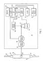
- FIG. 1is a schematic diagram of one embodiment of a medical pump according to the present invention.
- FIG. 2is schematic diagram of an alternative embodiment of a medical pump according to the present invention.
- FIG. 3is schematic diagram of another alternative embodiment of a medical pump according to the present invention.
- FIG. 4is schematic diagram of another alternative embodiment of a medical pump according to the present invention.
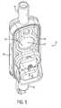
- FIG. 5is a perspective view of a cassette, which can be used as the pumping chamber in accordance with one embodiment of the present invention
- FIGS. 6-9are cross sectional views of the pumping element of the present invention driving a cassette through a pumping cycle
- FIG. 10is a graph plotting force data versus the pump plunger position from a pump cycle
- FIG. 11is a flow chart illustrating one embodiment of determining and adjusting the operating condition of a medical pump according to the present invention.
- FIG. 12is a flow chart illustrating a further embodiment of determining and adjusting the operating condition of a medical pump according to the present invention.
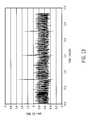
- FIG. 13is a graph of twenty second incremental bolus volume versus time using the present invention.
- a medical pump 10the functional components of one embodiment of a medical pump 10 are shown in schematic form.
- the medical pump 10is used in connection with a disposable fluid chamber, such as a cassette 12 for delivering a fluid to a patient.
- a disposable fluid chambersuch as a cassette 12 for delivering a fluid to a patient.
- the medical pump 10 of the present inventionprovides a mechanism for adjusting an actual delivery of fluid based on variations from nominal data used to estimate pump performance.
- the term medical pump as used hereinincludes but is not limited to enteral pumps, infusion pumps, cassette pumps, syringe pumps, peristaltic pumps, or any positive displacement fluid pumping device for the delivery of fluids intravenously or intra-arterially to a patient.
- the medical pump 10 and cassette 12are shown with several components for implementing the present invention. Those of ordinary skill in the art will appreciate that the pump 10 and cassette 12 may include many more components than those shown in FIG. 1 . However, it is not necessary that all these components be shown in order to disclose an illustrative embodiment for practicing the present invention.
- cassette 12suitable for use with the present invention is shown. It will be understood to one of ordinary skill in the art that a cassette or fluid chamber having a different design than that shown in FIG. 5 may be used with pump 10 without departing from the present invention.
- the cassette 12may include an inlet 14 and an outlet 16 formed in main body 18 .
- An inlet fluid line 20couples the inlet port 14 on the main body 18 to a fluid source (not shown) such as an IV bag or other fluid container.
- a fluid sourcesuch as an IV bag or other fluid container.
- an outlet fluid line 22couples the outlet port 16 on main body 18 to the body of a patient (not shown).
- a resilient elastomeric membrane or diaphragm 23forms a pumping chamber 24 , inlet valve 26 , and outlet valve 28 on an inner face 68 of the main body 18 .
- the pumping chamber 24is connected in fluid flow communication between the inlet port 14 and the outlet port 16 .
- the pumping chamber 24operates to meter fluid through the cassette 12 .
- the inlet valve 26resides between inlet port 14 and the pumping chamber 24 . Inlet valve 26 operates to physically open and close the fluid communication between inlet port 14 and pumping chamber 24 .
- outlet valve 28resides between the pumping chamber 24 and outlet port 16 .
- Outlet valve 28operates to physically open and close the fluid communication between pumping chamber 24 and outlet port 16 .
- the pumping chamber 24 , inlet valve 26 , and outlet valve 28are all operatively associated with the pump 10 to control the flow of fluid through the cassette 12 .
- the cassetteis a passive valve system requiring pressurization of the pumping chamber 24 prior to fluid delivery. Inlet valve 26 and outlet valve 28 react to the pressure of the pumping element 44 on the pumping chamber 24 .
- fluidenters through the inlet 14 and is forced through outlet 16 under pressure.
- the fluidis delivered to the outlet 16 when the pump 10 displaces the membrane 23 and thereby compresses the pumping chamber 24 to expel the fluid.
- the pumping cyclebegins with the pumping chamber 24 in a non-compressed position.
- the pumping chamber 24is compressed while the outlet valve 28 remains closed.
- the outlet valve 28opens and fluid flows to the outlet 16 .
- the pump 10releases the resilient membrane 23 over the pumping chamber 24 , and the fluid is then drawn through the inlet 14 and into the pumping chamber 24 once inlet valve 26 opens.
- the fluidflows from the cassette 12 in a series of spaced-apart pulses rather than in a continuous flow.
- the fluidis delivered to the patient at a pre-set rate, in a pre-determined manner, and only for a particular pre-selected time or total dosage.
- a processing unit 30is included in pump 10 and performs various operations described in greater detail below.
- An input/output device 32communicates with the processing unit 30 and allows the user to receive output from processing unit 30 and/or input information or commands into the processing unit 30 .
- input/output device 32may be provided as a separate display device and a separate input device.
- a memory 34communicates with the processing unit 30 and stores code and data necessary for the processing unit 30 to calculate and output the operating conditions of pump 10 . More specifically, the memory 34 stores a programming code 36 formed in accordance with the present invention for processing data to determine and control the operating condition of the pump 10 .
- a clock 37is used to keep time in the pump 10 .
- the clock 37is connected to the processing unit 30 , and provides the processing unit 30 with time information for correlating data over time or conducting time sensitive activities.
- An electric motor 38is controlled by processing unit 30 and is energized by a power supply 40 to serve as a prime mover for rotatably driving a shaft 42 connected to the motor 38 .
- the processing unit 30orders the motor 38 to run at different speeds depending on the flow rate desired through the pump 10 .
- the down-stroke or delivery portion of the strokehas the motor 38 running directly from power supply 40 .
- the up-stroke, retract or fill portion of the strokeis run at a voltage set by the processing unit 30 , so that the retract times are varied by the processing unit 30 , where higher desired flow rates require faster retract speeds.
- a pumping element 44is operatively associated with the shaft 42 .
- the pumping element 44When energized, the pumping element 44 reciprocates back and forth to periodically down-stroke, causing pumping element 44 to press on pumping chamber 24 , and expel fluid therefrom.
- pumping element 44On an up-stroke, pumping element 44 releases pressure from pumping chamber 24 and thereby draws fluid from inlet port 16 into pumping chamber 24 .
- the pumping element 44intermittently pressurizes the pumping chamber 24 during a pumping cycle.
- a pressure sensor 46is operatively associated with the pumping element 44 to detect the force or pressure exerted by the pumping element 44 on the pumping chamber 24 .
- the pressure sensor 46is directly connected to the pumping element and is positioned in-line with the pumping element 44 , between the pumping chamber 24 and the shaft 42 .
- the pressure sensor 46is the only pressure sensor included in the medical pump 10 , and operates to sense the force on pumping element 44 as well as to generate a pressure signal based on this force.
- the pressure sensor 46is in electronic communication with the processing unit 30 to send the pressure signal to the processing unit 30 for use in determining operating conditions of pump 10 .
- the pressure sensor 46may be a force transducer or any other device that can operatively sense the pressure brought to bear on the pumping chamber 24 by pumping element 44 .
- a position sensor 48is operatively associated with the pumping element 44 to directly or indirectly detect the position of the pumping element 44 .
- the position sensor 48tracks the pumping cycle of pump 10 by detecting the position of the pumping element 44 .
- the position sensor 48is associated with the shaft 42 .
- the position sensor 48generates a position signal by detecting the rotational position of the shaft 42 .
- the position sensor 48is in electronic communication with the processing unit 30 to send the position signal to the processing unit 30 .
- the processing unit 30utilizes this information to associate the incoming pressure data with a particular portion of the pump cycle.
- the position sensor 48could alternatively track a cam attached to the shaft 42 or the pumping element 44 .
- the position sensor 48 as used hereinincludes but is not limited to mechanical indicators such as pivoting dial indicators, electronic switches, Hall Effect sensors, and optical based position detectors.
- the pressure sensor 46comprises a current signal from the motor 38 .
- the current signal from the motor 38is proportional to the force exerted on the pumping chamber 24 through the pumping element 44 by the motor 38 .
- the pressure sensor 46is the only pressure sensor included in the medical pump 10 , and operates to sense the force on pumping element 44 as well as to generate a pressure signal to the processing unit 30 based on this force.
- the pressure sensor 46comprises a strain gauge directly connected to the pumping chamber 24 of the cassette 12 .
- the current signal from the strain gaugeis proportional to the force exerted on the pumping chamber 24 by the pumping element 44 .
- the pressure sensor 46is the only pressure sensor included in the medical pump 10 , and operates to sense the force on pumping element 44 as well as to generate a pressure signal to the processing unit 30 based on this force.
- the pressure sensor 46comprises a pressure probe located at least partially within the pumping chamber 24 of the cassette 12 .
- the current signal from pressure probeis proportional to the force exerted on the pumping chamber 24 by the pumping element 44 .
- the pressure sensor 46is the only pressure sensor included in the medical pump 10 , and operates to sense the force on pumping element 44 as well as to generate a pressure signal to the processing unit 30 based on this force.
- an exemplary force curveis shown where the pumping element 44 applies force pi (shown in psi units) to the pumping chamber 24 while moving in essentially a constant cyclic (sine-wave) motion through 360 degrees ⁇ i (shown in units of degrees) of rotation per cycle.
- the pumping element 44always has sufficient force available from the motor 38 so that its speed is essentially independent of the force p i applied to the pumping element 44 , and the outlet flow from pumping chamber 24 is not restricted.
- the curvestarts at 0 degrees or Bottom Dead Center (BDC) with the pumping element 44 deflecting the diaphragm 23 of the pumping chamber 24 a minimal amount at this point.
- BDCBottom Dead Center
- Cycle portion Ashows the pressurization of the pumping chamber 24 and is shown in this example as occurring from 0 to 30 degrees.
- the pumping element 44moves into the cassette 12 (which is called the pressurization stroke because fluid is compressed in pumping chamber 24 of the cassette 12 ) building force within the pumping chamber 24 , while the outlet valve 28 remains closed.
- the position of the pumping element 44 between 0 and 30 degrees, and the resultant displacement of pumping chamber 24can be seen in FIG. 7 .
- a delivery cycle portion Bbegins when the force within the pumping chamber 24 is sufficient to open the outlet valve 28 .
- the pumping element 44moves into the cassette 12 so as to build a force within the pumping chamber 24 sufficient to open the outlet valve 28 and expel fluids from the pumping chamber 24 .
- the delivery cycle portion Bis shown in this example as occurring from 30 to 180 degrees. The position of the pumping element 44 between 30 and 180 degrees, and the resultant opening of the outlet valve 28 can be seen in FIG. 8 .
- the delivery cycle portion Bends at Top Dead Center (TDC), or 180 degrees of rotation, and a depressurization cycle portion C begins.
- the depressurization cycle portion Cshows the depressurization the pumping chamber 24 and is shown in this example as occurring from 180 to 210 degrees.
- the pumping element 44moves out of the cassette 12 (which is called the up-stroke, depressurization or inlet stroke) and the force drops off.
- the diaphragm 23returns to its initial position, while the inlet valve 26 remains closed, negative pressure builds within the pumping chamber 24 .
- a refill cycle portion Dbegins when the negative pressure within the pumping chamber 24 is sufficient to the open the inlet valve 26 .
- the pumping element 44moves out the cassette 12 building negative pressure within the pumping chamber 24 sufficient to open the inlet valve 26 and draw fluids into the pumping chamber 24 .
- the refill cycle portion Dis shown in this example as occurring from 210 to 360 degrees, or Bottom Dead Center (BDC). The position of the pumping element 44 between 210 to 360 degrees, and the resultant opening of the inlet valve 26 can be seen in FIG. 9 .
- the pump 10 of the present inventionprovides a mechanism for controlling or adjusting an actual delivery of fluid based on variations from nominal data used to estimate pump performance.
- the processing unit 30retrieves the operating condition programming code 36 from memory 34 and applies it to the pressure and position data received during this pump cycle.
- the pump pressure data and pump position dataare processed by the processing unit 30 .
- Sensing the force that the resilient diaphragm 23 of the pumping chamber 24 exerts against the pumping element 44 and analyzing that forcecan determine an estimated volume of fluid flow per stroke (calculated stroke volume).
- the processing unit 30utilizes the calculated stroke volume in a closed loop stroke feedback system to modify the stroke frequency to compensate for variation in the stroke volume. In the closed loop stroke feedback system, the processing unit 30 adjusts an actual delivery of fluid based on variation between the calculated stroke volume and nominal data used to estimate pump performance.
- the processing unit 30begins execution of the programming code 36 at a block 50 and proceeds to block 52 where the processing unit 30 sets a stroke frequency for a desired dosage rate.
- the stroke frequencyis determined by the processing unit 30 based on a nominal stroke volume. This nominal stroke volume can be supplied from empirical evidence of an average normal stroke volume for all pumps of a particular type or for each individual pump.
- the processing unit 30proceeds to block 54 where it determines a calculated stroke volume of the pump for a pump cycle based on the pressure data from the pressure sensor 46 and position data from the position sensor 48 .
- the processing unit 30proceeds to decision block 56 where it determines if the calculated stroke volume is greater than a given threshold value.
- the threshold value disclosed hereinis predetermined from experimental data, and will vary from pump model to pump model.
- the processing unit 30retrieves the operating condition programming code 36 from memory 34 and applies it to the pressure and position data received during this pump cycle.
- the pump pressure data and pump position dataare processed by the processing unit 30 .
- Sensing the force that the diaphragm 23 of the pumping chamber 24 exerts against the pumping element 44 and analyzing that forcecan determine an estimated volume of fluid flow per stroke (calculated stroke volume).
- the processing unit 30utilizes the calculated stroke volume in a closed loop stroke feedback system to modify the stroke frequency to compensate for variation in the stroke volume. In the closed loop stroke feedback system, the processing unit 30 adjusts an actual delivery of fluid based on variation between the calculated stroke volume and nominal data used to estimate pump performance.
- the processing unit 30begins execution of the programming code 36 at a block 62 and proceeds to block 64 where the processing unit 30 sets a stroke frequency for a desired dosage rate. Like step 52 from FIG. 10 , the stroke frequency is determined by the processing unit 30 based on a nominal stroke volume.
- the processing unit 30proceeds to block 66 where the processing unit 30 determines when an outlet valve 28 of the pumping chamber opens.
- the processing unit 30determines the opening of outlet valve 28 based on data from the pressurization cycle portion A (as shown in FIG. 10 ). During the pressurization cycle portion A pumping element 44 moves into the cassette 12 building force within the pumping chamber 24 to a point where the outlet valve 28 opens.
- the opening of the outlet valve 28can be determined. For instance, by taking the derivative of the pressure data over time, where the pressure derivate is greater than zero in the following equation:
- the processing unit 30determines at what angular position the pumping element 44 was in when the outlet valve 28 opened (i.e., where dp/dt changes from >0 to ⁇ 0).
- the processing unit 30proceeds to block 68 where the processing unit 30 determines a calculated pressurization volume from the beginning of the pump cycle to the point when the outlet valve opens.
- the processing unit 30determines the calculated pressurization volume based on data from the pressurization cycle portion A (as shown in FIG. 10 ).
- pumping element 44moves into the cassette 12 building force within the pumping chamber 24 , while the outlet valve 28 remains closed.
- the processing unit 30converts the displacement distance x i into a pressurization stroke volume based on a ratio of volume to displacement distance for the pump 10 . This ratio is based on a nominal pressurization volume and a nominal displacement distance for a typical pump 10 . This pressurization volume and a nominal displacement distance can be supplied from empirical evidence of an average normal stroke volume for all pumps of a particular type or for each individual pump.
- the processing unit 30proceeds to block 70 where the processing unit 30 determines a change in pressurization volume by subtracting the calculated pressurization volume from a nominal pressurization volume.
- the nominal pressurization volumecan be supplied from empirical evidence of an average normal stroke volume for all pumps of a particular type or for each individual pump.
- the change in pressurization volume determined hereis proportional to variations in the actual stroke volume, as a portion of compressive forces can be lost and not translated into fluid delivery. For instance, a portion of compressive forces can be lost where there is excessive compliance within mechanical components (such as the cassette 12 ) or air bubble entrained within the pumping chamber 24 .
- the processing unit 30proceeds to block 72 where the processing unit 30 determines a change in stroke volume by multiplying the change in pressurization volume by a ratio of pumping chamber expansion under pressure at the middle of the pumping cycle to pumping chamber expansion under pressure at the start of the pumping cycle.
- This “pumping chamber expansion under pressure”is also referred to as the compliance of the pumping chamber.
- the diaphragm 23 of the cassette 12is constructed of various materials with corresponding spring rates. As pressure is placed on the pumping chamber 24 , the volume of the chamber 24 changes according to the overall spring rate of the cassette 12 . As the volume of the pumping chamber 24 will grow larger as pressure increases. However, the pumping chamber compliance is not the same throughout the pumping cycle.
- the compliance(ratio of volume change to pressure) is higher than the compliance at the middle of the pumping cycle (180 degrees).
- the compliancecan be supplied from empirical evidence of an average normal stroke volume for all pumps of a particular type or for each individual pump.
- the change in pressurization volumeis multiplied by a ratio of compliance at the middle of the pumping cycle to the compliance at the beginning of the pumping cycle.
- the processing unit 30proceeds to block 74 where the processing unit 30 determines a calculated stroke volume based on the change in stroke volume. Specifically, the change in stroke volume is added to the nominal stroke volume to arrive at the calculated stroke volume. This calculated stroke volume provides a very close estimate of the actual individual stroke volume delivered.
- the processing unit 30proceeds to decision block 76 where it determines if the calculated stroke volume is greater than a given threshold value.
- a given threshold valueOne of ordinary skill in the art will understand that the threshold value disclosed herein is predetermined from experimental data, and will vary from pump model to pump model. If the result from decision block 76 is negative, then the execution of the programming code 36 by the processing unit 30 is complete and ends in block 80 .
- the processing unit 30proceeds to block 78 where it adjusts the stroke frequency to compensate for the variation between the calculated stroke volume and the nominal stroke volume. Once the stroke frequency has been adjusted, the execution of the programming code 36 by the processing unit 30 is complete and ends in block 80 .
- the threshold determination above from block 76could be made on criterional information other than the calculated stroke volume above.
- the threshold determination 76could similarly be made based on the angle at which the outlet valve 28 opens, the calculated pressure volume, the change in pressurization volume, or the change in stroke volume determined above. In any of these cases, the given threshold value would necessarily be scaled according to the designated alternative criterional information. Additionally, the timing of the threshold determination 76 could also be adjusted based on the designated alternative criterional information. For instance, were the calculated pressurization volume designated as the alternative criterional information, the threshold determination 76 could occur at any point after step 68 .
- the stroke frequency adjustment above from block 78could be made on criterional information other than the calculated stroke volume above.
- the stroke frequency adjustment 78could similarly be made based on the angle at which the outlet valve 28 opens, the calculated pressure volume, the change in pressurization volume, or the change in stroke volume determined above. In any of these cases, the stroke frequency adjustment 78 would necessarily be scaled according to the designated alternative criterional information.
- the timing of the stroke frequency adjustment 78could also be adjusted based on the designated alternative criterional information. For instance, were the calculated pressurization volume designated as the alternative criterional information, the stroke frequency adjustment 78 could occur at any point after step 68 .
- the calculated stroke volumecould comprise multiple calculated stroke volumes averaged together. This averaging of multiple calculated stroke volumes potentially reduces the effects that minor variations in stroke volume and/or statistical noise have to the overall pump 10 operation.
- the above closed loop stroke feedback system embodimentsprovide several advantages.
- the first advantageis that the actual volume delivered per stroke can be used by the processing unit 30 to continuously adjust the stroke rate.
- the second advantageis that the detection of the pressure data profile and the determination of the opening of outlet valve 28 permits the processing unit 30 to determine lost stroke volume (i.e. calculated stroke volume as compared with the nominal stroke volume) and to use this as an indicator of presence of air in the pumping chamber 24 , as well as determining the size of air bubbles in the set.
- lost stroke volumei.e. calculated stroke volume as compared with the nominal stroke volume
- These advantages of the present inventionlimit the effects of all causes of delivery error, including: compliance of physical components, air in the delivery fluid, variations in line pressure, and manufacturing variability of physical components (for example, in valve opening pressures).
- the present inventionis particularly advantageous.
- the cassettesare disposable, the cassettes are produced in very high volumes there are limitations to reducing the manufacturing variability of the physical components and assemblies.
- the overall accuracy provided by present inventionimproves the ability to perform accurate deliveries within a broader range of these manufacturing variabilities of the physical components and assemblies.
- the third advantageis that the detection of the pressure data profile and the determination of the opening of outlet valve 28 permits the processing unit 30 to deliver in smaller increments for very low flow rates in a more continuous manner (known as Low Flow Continuity).
- Low Flow Continuityis defined as the ability of a pump to deliver at rates of 1 ml/hr to 0.1 ml/hr or less with periods of “no-flow” not exceeding 20 seconds and bolus volumes not exceeding 2 micro-liters.
- the pumpTo meet the highest Emergency Care Research Institute (ECRI) industry standards for Low Flow Continuity and achieve an “Excellent” ECRI rating, the pump must deliver fluid in increments no greater than two micro-liters at a flow rate of 0.1 milliliter per hour with a maximum “no-flow” period of 20 seconds.
- ECRIEmergency Care Research Institute
- the present inventionprovides means for reciprocating a plunger mechanism 44 of a medical pump 10 to deliver fluid in smaller increments for very low flow rates in a more continuous manner sufficient to meet and exceed the above ECRI standards.
- FIG. 13displays a pump delivering fluid with a low flow continuity of about 1 ml/hr or less, more specifically about 0.1 ml/hr or less, with twenty second incremental bolus volumes of less than 2 ⁇ l using the present invention.
- the same pumpis also programmable to deliver up to 1000 ml/hr.
Landscapes
- Health & Medical Sciences (AREA)
- Vascular Medicine (AREA)
- Engineering & Computer Science (AREA)
- Anesthesiology (AREA)
- Biomedical Technology (AREA)
- Heart & Thoracic Surgery (AREA)
- Hematology (AREA)
- Life Sciences & Earth Sciences (AREA)
- Animal Behavior & Ethology (AREA)
- General Health & Medical Sciences (AREA)
- Public Health (AREA)
- Veterinary Medicine (AREA)
- Infusion, Injection, And Reservoir Apparatuses (AREA)
- Reciprocating Pumps (AREA)
Abstract
Description
the pressure within the pumping
the pressure within the pumping
xi=Lcam*(1−cos(θi))
where xiis the displacement distance, Lcamis half the distance of a stroke for the
Claims (37)
Priority Applications (5)
| Application Number | Priority Date | Filing Date | Title |
|---|---|---|---|
| US10/810,123US8313308B2 (en) | 2004-03-26 | 2004-03-26 | Medical infusion pump with closed loop stroke feedback system and method |
| PCT/US2005/010010WO2005097235A2 (en) | 2004-03-26 | 2005-03-23 | Medical infusion pump with closed loop stroke feedback system and method |
| CA2561259ACA2561259C (en) | 2004-03-26 | 2005-03-23 | Medical infusion pump with closed loop stroke feedback system and method |
| EP05729886.1AEP1727575B1 (en) | 2004-03-26 | 2005-03-23 | Medical infusion pump with closed loop feedback system |
| US11/510,106US7905710B2 (en) | 2004-03-26 | 2006-08-25 | System and method for improved low flow medical pump delivery |
Applications Claiming Priority (1)
| Application Number | Priority Date | Filing Date | Title |
|---|---|---|---|
| US10/810,123US8313308B2 (en) | 2004-03-26 | 2004-03-26 | Medical infusion pump with closed loop stroke feedback system and method |
Related Child Applications (1)
| Application Number | Title | Priority Date | Filing Date |
|---|---|---|---|
| US11/510,106Continuation-In-PartUS7905710B2 (en) | 2004-03-26 | 2006-08-25 | System and method for improved low flow medical pump delivery |
Publications (2)
| Publication Number | Publication Date |
|---|---|
| US20050214129A1 US20050214129A1 (en) | 2005-09-29 |
| US8313308B2true US8313308B2 (en) | 2012-11-20 |
Family
ID=34963939
Family Applications (1)
| Application Number | Title | Priority Date | Filing Date |
|---|---|---|---|
| US10/810,123Expired - LifetimeUS8313308B2 (en) | 2004-03-26 | 2004-03-26 | Medical infusion pump with closed loop stroke feedback system and method |
Country Status (4)
| Country | Link |
|---|---|
| US (1) | US8313308B2 (en) |
| EP (1) | EP1727575B1 (en) |
| CA (1) | CA2561259C (en) |
| WO (1) | WO2005097235A2 (en) |
Cited By (43)
| Publication number | Priority date | Publication date | Assignee | Title |
|---|---|---|---|---|
| US20100143155A1 (en)* | 2008-04-02 | 2010-06-10 | Preiswerk Thomas | Piston Pump Having A Force Sensor And A Method For Controlling Said Pump |
| US20110005605A1 (en)* | 2008-04-09 | 2011-01-13 | Arkray, Inc. | Liquid delivery control method and liquid delivery control system |
| US20110254686A1 (en)* | 2010-04-16 | 2011-10-20 | Medtronic, Inc. | Reservoir monitoring for implantable fluid delivery devices |
| US8568389B2 (en) | 2011-04-13 | 2013-10-29 | Medtronic, Inc. | Estimating the volume of fluid in therapeutic fluid delivery device reservoir |
| US20150137017A1 (en)* | 2013-11-15 | 2015-05-21 | Ivenix, Inc. | Fluid flow regulator assembly |
| US9119917B2 (en) | 2009-03-31 | 2015-09-01 | Tandem Diabetes Care, Inc. | Systems and methods to address air, leaks and occlusions in an insulin pump system |
| US20150292500A1 (en)* | 2012-11-09 | 2015-10-15 | Fresenius Vial Sas | Method for operating a peristaltic pump |
| US20160287767A1 (en)* | 2015-04-06 | 2016-10-06 | Medela Holding Ag | Breastmilk expression system with detection, feedback and connectability features |
| US9468718B2 (en) | 2012-09-08 | 2016-10-18 | Hospira, Inc. | Means and method for detecting free flow in an infusion line |
| US9677555B2 (en) | 2011-12-21 | 2017-06-13 | Deka Products Limited Partnership | System, method, and apparatus for infusing fluid |
| US9675756B2 (en) | 2011-12-21 | 2017-06-13 | Deka Products Limited Partnership | Apparatus for infusing fluid |
| US9687603B2 (en) | 2010-04-16 | 2017-06-27 | Medtronic, Inc. | Volume monitoring for implantable fluid delivery devices |
| US9995611B2 (en) | 2012-03-30 | 2018-06-12 | Icu Medical, Inc. | Air detection system and method for detecting air in a pump of an infusion system |
| US10022498B2 (en) | 2011-12-16 | 2018-07-17 | Icu Medical, Inc. | System for monitoring and delivering medication to a patient and method of using the same to minimize the risks associated with automated therapy |
| US10046112B2 (en) | 2013-05-24 | 2018-08-14 | Icu Medical, Inc. | Multi-sensor infusion system for detecting air or an occlusion in the infusion system |
| US10143795B2 (en) | 2014-08-18 | 2018-12-04 | Icu Medical, Inc. | Intravenous pole integrated power, control, and communication system and method for an infusion pump |
| US10166328B2 (en) | 2013-05-29 | 2019-01-01 | Icu Medical, Inc. | Infusion system which utilizes one or more sensors and additional information to make an air determination regarding the infusion system |
| US10265463B2 (en) | 2014-09-18 | 2019-04-23 | Deka Products Limited Partnership | Apparatus and method for infusing fluid through a tube by appropriately heating the tube |
| US10342917B2 (en) | 2014-02-28 | 2019-07-09 | Icu Medical, Inc. | Infusion system and method which utilizes dual wavelength optical air-in-line detection |
| US10430761B2 (en) | 2011-08-19 | 2019-10-01 | Icu Medical, Inc. | Systems and methods for a graphical interface including a graphical representation of medical data |
| US10463788B2 (en) | 2012-07-31 | 2019-11-05 | Icu Medical, Inc. | Patient care system for critical medications |
| US10596316B2 (en) | 2013-05-29 | 2020-03-24 | Icu Medical, Inc. | Infusion system and method of use which prevents over-saturation of an analog-to-digital converter |
| US10635784B2 (en) | 2007-12-18 | 2020-04-28 | Icu Medical, Inc. | User interface improvements for medical devices |
| US10656894B2 (en) | 2017-12-27 | 2020-05-19 | Icu Medical, Inc. | Synchronized display of screen content on networked devices |
| US10850024B2 (en) | 2015-03-02 | 2020-12-01 | Icu Medical, Inc. | Infusion system, device, and method having advanced infusion features |
| US10918787B2 (en) | 2015-05-26 | 2021-02-16 | Icu Medical, Inc. | Disposable infusion fluid delivery device for programmable large volume drug delivery |
| US11135360B1 (en) | 2020-12-07 | 2021-10-05 | Icu Medical, Inc. | Concurrent infusion with common line auto flush |
| USD939079S1 (en) | 2019-08-22 | 2021-12-21 | Icu Medical, Inc. | Infusion pump |
| US11213619B2 (en) | 2013-11-11 | 2022-01-04 | Icu Medical, Inc. | Thermal management system and method for medical devices |
| US11246985B2 (en) | 2016-05-13 | 2022-02-15 | Icu Medical, Inc. | Infusion pump system and method with common line auto flush |
| US11278671B2 (en) | 2019-12-04 | 2022-03-22 | Icu Medical, Inc. | Infusion pump with safety sequence keypad |
| US11295846B2 (en) | 2011-12-21 | 2022-04-05 | Deka Products Limited Partnership | System, method, and apparatus for infusing fluid |
| US11324888B2 (en) | 2016-06-10 | 2022-05-10 | Icu Medical, Inc. | Acoustic flow sensor for continuous medication flow measurements and feedback control of infusion |
| US11344668B2 (en) | 2014-12-19 | 2022-05-31 | Icu Medical, Inc. | Infusion system with concurrent TPN/insulin infusion |
| US11344673B2 (en) | 2014-05-29 | 2022-05-31 | Icu Medical, Inc. | Infusion system and pump with configurable closed loop delivery rate catch-up |
| US11707615B2 (en) | 2018-08-16 | 2023-07-25 | Deka Products Limited Partnership | Medical pump |
| US11883361B2 (en) | 2020-07-21 | 2024-01-30 | Icu Medical, Inc. | Fluid transfer devices and methods of use |
| US11911595B2 (en) | 2020-05-18 | 2024-02-27 | Tandem Diabetes Care, Inc. | Systems and methods for automated insulin delivery response to meal announcements |
| US11951284B2 (en) | 2020-08-27 | 2024-04-09 | Tandem Diabetes Care, Inc. | Transitioning to other modes in automated insulin delivery |
| US12098738B2 (en) | 2011-12-21 | 2024-09-24 | Deka Products Limited Partnership | System, method, and apparatus for clamping |
| USD1052728S1 (en) | 2021-11-12 | 2024-11-26 | Icu Medical, Inc. | Medical fluid infusion pump |
| US12350233B2 (en) | 2021-12-10 | 2025-07-08 | Icu Medical, Inc. | Medical fluid compounding systems with coordinated flow control |
| USD1091564S1 (en) | 2021-10-13 | 2025-09-02 | Icu Medical, Inc. | Display screen or portion thereof with graphical user interface for a medical device |
Families Citing this family (71)
| Publication number | Priority date | Publication date | Assignee | Title |
|---|---|---|---|---|
| EP2301749A1 (en)* | 2003-06-27 | 2011-03-30 | Novo Nordisk A/S | High moisture barrier container for medical liquid compositions |
| ATE483580T1 (en)* | 2003-12-22 | 2010-10-15 | Novo Nordisk As | CLEAR, FLEXIBLE, WATERPROOF PLASTIC CONTAINER FOR STORING PHARMACEUTICAL LIQUIDS |
| US8313308B2 (en) | 2004-03-26 | 2012-11-20 | Hospira, Inc. | Medical infusion pump with closed loop stroke feedback system and method |
| US7905710B2 (en)* | 2004-03-26 | 2011-03-15 | Hospira, Inc. | System and method for improved low flow medical pump delivery |
| EP1738896A1 (en)* | 2005-06-28 | 2007-01-03 | Novo Nordisk A/S | Multilayer film with septum layer |
| US20070093753A1 (en)* | 2005-09-19 | 2007-04-26 | Lifescan, Inc. | Malfunction Detection Via Pressure Pulsation |
| US20070066940A1 (en)* | 2005-09-19 | 2007-03-22 | Lifescan, Inc. | Systems and Methods for Detecting a Partition Position in an Infusion Pump |
| WO2007035654A2 (en)* | 2005-09-19 | 2007-03-29 | Lifescan, Inc. | Systems and methods for detecting a partition position in an infusion pump |
| EP1979026A2 (en)* | 2006-01-06 | 2008-10-15 | Novo Nordisk A/S | A medication delivery device applying a collapsible reservoir |
| US12070574B2 (en) | 2006-02-09 | 2024-08-27 | Deka Products Limited Partnership | Apparatus, systems and methods for an infusion pump assembly |
| US12370305B2 (en) | 2006-02-09 | 2025-07-29 | Deka Products Limited Partnership | Patch-sized fluid delivery systems and methods |
| US11497846B2 (en) | 2006-02-09 | 2022-11-15 | Deka Products Limited Partnership | Patch-sized fluid delivery systems and methods |
| US8579884B2 (en) | 2006-02-09 | 2013-11-12 | Deka Products Limited Partnership | Infusion pump assembly |
| US11364335B2 (en) | 2006-02-09 | 2022-06-21 | Deka Products Limited Partnership | Apparatus, system and method for fluid delivery |
| US11478623B2 (en) | 2006-02-09 | 2022-10-25 | Deka Products Limited Partnership | Infusion pump assembly |
| EP3165247B1 (en) | 2006-02-09 | 2020-10-28 | DEKA Products Limited Partnership | Pumping fluid delivery systems and methods using force application assembley |
| US11027058B2 (en) | 2006-02-09 | 2021-06-08 | Deka Products Limited Partnership | Infusion pump assembly |
| US10010669B2 (en) | 2006-02-09 | 2018-07-03 | Deka Products Limited Partnership | Systems and methods for fluid delivery |
| US12151080B2 (en) | 2006-02-09 | 2024-11-26 | Deka Products Limited Partnership | Adhesive and peripheral systems and methods for medical devices |
| US12274857B2 (en) | 2006-02-09 | 2025-04-15 | Deka Products Limited Partnership | Method and system for shape-memory alloy wire control |
| EP2316505B1 (en) | 2006-03-14 | 2017-01-18 | University Of Southern California | Mems device for delivery of therapeutic agents |
| US8211054B2 (en) | 2006-05-01 | 2012-07-03 | Carefusion 303, Inc. | System and method for controlling administration of medical fluid |
| US9162016B2 (en)* | 2006-09-22 | 2015-10-20 | Medela Holding Ag | Breastpump with irregular milk expression sequences |
| US20100030092A1 (en)* | 2006-11-14 | 2010-02-04 | Novo Nordisk A/S | Adaptive Hypoglycaemia Alert System and Method |
| US7654127B2 (en)* | 2006-12-21 | 2010-02-02 | Lifescan, Inc. | Malfunction detection in infusion pumps |
| CA2677667A1 (en) | 2007-02-09 | 2008-08-14 | Deka Products Limited Partnership | Automated insertion assembly |
| EP2134388B1 (en)* | 2007-03-07 | 2012-12-19 | Novo Nordisk A/S | A medication delivery device comprising a plurality of reservoirs |
| US8070715B2 (en)* | 2007-04-11 | 2011-12-06 | Medela Holding Ag | Method and apparatus for minimum negative pressure control, particularly for breastpump with breastshield pressure control system |
| US8070716B2 (en)* | 2007-04-11 | 2011-12-06 | Medela Holding Ag | Method and apparatus for minimum negative pressure control, particularly for a breastpump with breastshield pressure control system |
| US8007247B2 (en) | 2007-05-22 | 2011-08-30 | Medtronic, Inc. | End of stroke detection for electromagnetic pump |
| US7981082B2 (en)* | 2007-08-21 | 2011-07-19 | Hospira, Inc. | System and method for reducing air bubbles in a fluid delivery line |
| WO2009039214A2 (en) | 2007-09-17 | 2009-03-26 | Satish Sundar | High precision infusion pumps |
| US8062008B2 (en) | 2007-09-27 | 2011-11-22 | Curlin Medical Inc. | Peristaltic pump and removable cassette therefor |
| US8083503B2 (en) | 2007-09-27 | 2011-12-27 | Curlin Medical Inc. | Peristaltic pump assembly and regulator therefor |
| US7934912B2 (en) | 2007-09-27 | 2011-05-03 | Curlin Medical Inc | Peristaltic pump assembly with cassette and mounting pin arrangement |
| WO2009086112A2 (en) | 2007-12-20 | 2009-07-09 | University Of Southern California | Apparatus and methods for delivering therapeutic agents |
| US8881774B2 (en) | 2007-12-31 | 2014-11-11 | Deka Research & Development Corp. | Apparatus, system and method for fluid delivery |
| US8900188B2 (en) | 2007-12-31 | 2014-12-02 | Deka Products Limited Partnership | Split ring resonator antenna adapted for use in wirelessly controlled medical device |
| US10080704B2 (en) | 2007-12-31 | 2018-09-25 | Deka Products Limited Partnership | Apparatus, system and method for fluid delivery |
| CA2919786C (en) | 2007-12-31 | 2019-10-22 | Deka Products Limited Partnership | Infusion pump assembly |
| US9526830B2 (en) | 2007-12-31 | 2016-12-27 | Deka Products Limited Partnership | Wearable pump assembly |
| US10188787B2 (en) | 2007-12-31 | 2019-01-29 | Deka Products Limited Partnership | Apparatus, system and method for fluid delivery |
| US9456955B2 (en) | 2007-12-31 | 2016-10-04 | Deka Products Limited Partnership | Apparatus, system and method for fluid delivery |
| WO2009120692A2 (en)* | 2008-03-25 | 2009-10-01 | Animal Innovations, Inc. | Syringe mechanism for detecting syringe status |
| US9849238B2 (en) | 2008-05-08 | 2017-12-26 | Minipumps, Llc | Drug-delivery pump with intelligent control |
| JP5719767B2 (en) | 2008-05-08 | 2015-05-20 | ミニパンプス, エルエルシー | Implantable pump and cannula therefor |
| US8486278B2 (en) | 2008-05-08 | 2013-07-16 | Minipumps, Llc | Drug-delivery pumps and methods of manufacture |
| WO2011008966A2 (en) | 2009-07-15 | 2011-01-20 | Deka Products Limited Partnership | Apparatus, systems and methods for an infusion pump assembly |
| KR101697388B1 (en) | 2009-08-18 | 2017-01-17 | 미니펌프스, 엘엘씨 | Electrolytic drug-delivery pump with adaptive control |
| CH702436A1 (en)* | 2009-12-23 | 2011-06-30 | Jean-Denis Rochat | DOSING PUMP FOR MEDICAL USE. |
| EP2519288B1 (en) | 2009-12-31 | 2016-04-13 | DEKA Products Limited Partnership | Infusion pump assembley |
| CA3033439C (en) | 2010-01-22 | 2021-04-06 | Deka Products Limited Partnership | Method and system for shape-memory alloy wire control |
| CN103108665A (en)* | 2010-04-20 | 2013-05-15 | 迷你泵有限责任公司 | Electrolytically driven drug pump devices |
| US8858185B2 (en) | 2010-06-23 | 2014-10-14 | Hospira, Inc. | Fluid flow rate compensation system using an integrated conductivity sensor to monitor tubing changes |
| US8777590B2 (en) | 2010-12-22 | 2014-07-15 | Hospira, Inc. | Fluid delivery device identification and loading system |
| US11524151B2 (en) | 2012-03-07 | 2022-12-13 | Deka Products Limited Partnership | Apparatus, system and method for fluid delivery |
| US9617020B2 (en) | 2013-07-03 | 2017-04-11 | Deka Products Limited Partnership | Apparatus, system and method for fluid delivery |
| JP6475957B2 (en) | 2014-11-27 | 2019-02-27 | 日東電工株式会社 | Dosing mechanism |
| US10293102B2 (en) | 2014-12-01 | 2019-05-21 | Carefusion 2200, Inc. | Pump cassettes with piston and infusion pump systems |
| US10363360B2 (en)* | 2014-12-01 | 2019-07-30 | Carefusion 2200, Inc. | Pump cassettes with slider and infusion pump systems |
| US10245373B2 (en) | 2014-12-01 | 2019-04-02 | Carefusion 2200, Inc. | Pump cassettes with positioning feature and infusion pump systems |
| US10376639B2 (en) | 2014-12-01 | 2019-08-13 | Carefusion 2200, Inc. | Valving system for infusion cassette |
| AU2018247005B2 (en) | 2017-03-31 | 2023-09-21 | Becton, Dickinson And Company | Smart wearable injection and/or infusion device |
| US11504472B2 (en) | 2017-07-06 | 2022-11-22 | Quasuras, Inc. | Medical pump with flow control |
| CA3098372A1 (en) | 2018-04-24 | 2019-10-31 | Deka Products Limited Partnership | Apparatus and system for fluid delivery |
| US12318576B2 (en)* | 2019-03-05 | 2025-06-03 | Eitan Medical Ltd. | Infusion pump with toggling capability |
| WO2021113538A1 (en) | 2019-12-06 | 2021-06-10 | Quasuras, Inc. | Training cartridge for medical pump systems |
| US11817197B2 (en) | 2020-02-07 | 2023-11-14 | Quasuras, Inc. | Medical pump electronic pairing with device |
| US11925577B2 (en) | 2020-04-17 | 2024-03-12 | Bausch + Lomb Ireland Limted | Hydrodynamically actuated preservative free dispensing system |
| US11938057B2 (en)* | 2020-04-17 | 2024-03-26 | Bausch + Lomb Ireland Limited | Hydrodynamically actuated preservative free dispensing system |
| US12290472B2 (en) | 2020-04-17 | 2025-05-06 | Bausch + Lomb Ireland Limited | Hydrodynamically actuated preservative free dispensing system |
Citations (54)
| Publication number | Priority date | Publication date | Assignee | Title |
|---|---|---|---|---|
| US3985467A (en) | 1975-05-27 | 1976-10-12 | Milton Roy Company | Constant pressure pump |
| US4078562A (en) | 1976-08-16 | 1978-03-14 | Diana W. Friedman | Infusion pump with feedback control |
| US4308866A (en) | 1978-11-02 | 1982-01-05 | University Of Southern California | Infusion controlling apparatus and method |
| US4411651A (en) | 1981-05-26 | 1983-10-25 | Pacesetter Systems, Inc. | Device and method useful in monitoring fluid flow in a drug injector |
| US4453931A (en) | 1980-08-01 | 1984-06-12 | Oximetrix, Inc. | Intravenous metering device |
| US4617014A (en) | 1985-11-26 | 1986-10-14 | Warner-Lambert Company | Dual mode I. V. infusion device |
| US4696671A (en) | 1984-02-08 | 1987-09-29 | Omni-Flow, Inc. | Infusion system having plural fluid input ports and at least one patient output port |
| US4741736A (en) | 1986-12-10 | 1988-05-03 | I-Flow Corporation | Programmable infusion pump |
| EP0282323A2 (en) | 1987-03-13 | 1988-09-14 | Fresenius AG | Pump control system |
| EP0291727A2 (en) | 1987-05-01 | 1988-11-23 | Abbott Laboratories | Pressure sensor assembly for disposable pump cassette |
| US4846792A (en) | 1988-03-08 | 1989-07-11 | Baxter International Inc. | Automatic infiltration detection system and method |
| US4886422A (en) | 1987-07-09 | 1989-12-12 | Tokyo Keiki Company Ltd. | Control apparatus of variable delivery pump |
| US4898576A (en) | 1986-06-06 | 1990-02-06 | Philip James H | Intravenous fluid flow monitor |
| US4919595A (en)* | 1987-03-03 | 1990-04-24 | Beckman Instruments, Inc. | Fluid delivery system with deficit flow compensation |
| US4927411A (en) | 1987-05-01 | 1990-05-22 | Abbott Laboratories | Drive mechanism for disposable fluid infusion pumping cassette |
| WO1991000113A2 (en) | 1989-06-22 | 1991-01-10 | Baxter International Inc. | Infusion system, methodology, and algorithm for identifying patient-induced pressure artifacts |
| US5006050A (en) | 1988-12-09 | 1991-04-09 | James E. Cooke | High accuracy disposable cassette infusion pump |
| US5116312A (en) | 1989-11-03 | 1992-05-26 | The Uab Research Foundation | Method and apparatus for automatic autotransfusion |
| US5174472A (en) | 1991-04-18 | 1992-12-29 | Raque Food Systems, Inc. | Control system for timing a sequence of events |
| US5292306A (en) | 1993-01-29 | 1994-03-08 | Abbott Laboratories | Method of detecting occlusions in a solution pumping system |
| US5399171A (en) | 1991-06-10 | 1995-03-21 | Baxter International Inc. | Intravenous metering monitoring device |
| US5464392A (en)* | 1984-02-08 | 1995-11-07 | Abbott Laboratories | Infusion system having plural fluid input ports and at least one patient output port |
| US5482438A (en) | 1994-03-09 | 1996-01-09 | Anderson; Robert L. | Magnetic detent and position detector for fluid pump motor |
| US5551850A (en) | 1994-03-09 | 1996-09-03 | Baxter International Inc. | Pump chamber and valve assembly |
| US5554013A (en) | 1992-05-01 | 1996-09-10 | Mcgaw, Inc. | Disposable cassette with negative head height fluid supply |
| US5586868A (en)* | 1994-05-13 | 1996-12-24 | Abbott Laboratories | Method of delivering liquid to a patient via a disposable pumping cassette having a flow control & pressure monitoring member |
| US5658133A (en) | 1994-03-09 | 1997-08-19 | Baxter International Inc. | Pump chamber back pressure dissipation apparatus and method |
| WO1998004304A1 (en) | 1996-07-30 | 1998-02-05 | Alaris Medical Systems, Inc. | Fluid flow resistance monitoring system |
| US5938636A (en) | 1997-06-20 | 1999-08-17 | The Bd Of Regents Of The University Of California | Autoinfuser for resuscitation and method of infusion fluid injection |
| US5957890A (en) | 1997-06-09 | 1999-09-28 | Minimed Inc. | Constant flow medication infusion pump |
| WO1999052575A1 (en) | 1998-04-10 | 1999-10-21 | Milestone Scientific, Inc. | Pressure/force computer controlled drug delivery system and the like |
| EP0960627A2 (en) | 1998-05-25 | 1999-12-01 | B. Braun Melsungen Ag | Central Infusion Pump Controlling and/or Monitoring Device |
| WO2000013726A1 (en) | 1998-09-04 | 2000-03-16 | Alaris Medical Systems, Inc. | Fluid flow resistance monitoring system |
| US6259587B1 (en) | 1999-06-17 | 2001-07-10 | Minimed Inc. | Direct current motor safety circuits for fluid delivery systems |
| US20010007636A1 (en)* | 1998-08-03 | 2001-07-12 | Butterfield Robert D. | System and method for increased flow uniformity |
| US6267559B1 (en) | 1999-12-21 | 2001-07-31 | Alaris Medical Systems, Inc. | Apparatus and method for reducing power consumption in a peristaltic pump mechanism |
| US20020013545A1 (en) | 1998-01-29 | 2002-01-31 | David Soltanpour | Synthetic muscle based diaphragm pump apparatuses |
| US20020018720A1 (en) | 2000-07-07 | 2002-02-14 | Fluidsense Corporation | Controlled force fluid delivery system |
| WO2002087664A2 (en) | 2001-04-25 | 2002-11-07 | Abbott Laboratories | Disposable infusion cassette with low air bubble retention and improved valves |
| US20020168278A1 (en)* | 2001-01-08 | 2002-11-14 | Jeon Noo Li | Valves and pumps for microfluidic systems and method for making microfluidic systems |
| US20020183693A1 (en) | 1992-09-09 | 2002-12-05 | Sims Deltec, Inc. | Drug pump systems and methods |
| US6497680B1 (en) | 1999-12-17 | 2002-12-24 | Abbott Laboratories | Method for compensating for pressure differences across valves in cassette type IV pump |
| US20030091442A1 (en) | 2001-11-09 | 2003-05-15 | Bush Matthew D. | Liquid dispensing pump system |
| US20040047736A1 (en) | 2002-09-10 | 2004-03-11 | Miwatec Incorporated | Methods and apparatus for controlling a continuous flow rotary blood pump |
| WO2004035115A1 (en) | 2002-10-16 | 2004-04-29 | Abbott Laboratories | Method for discriminating between operating conditions in medical pump |
| US20040120825A1 (en) | 2002-10-16 | 2004-06-24 | Bouton Chad E. | Method for discriminating between operating conditions in medical pump |
| US20040247445A1 (en)* | 2002-10-16 | 2004-12-09 | Nelson Steven R. | Means for using single force sensor to supply all necessary information for determination of status of medical pump |
| WO2004112579A2 (en) | 2003-06-20 | 2004-12-29 | Sound Surgical Technolgies, Llc | Precision fluid delivery system and method for surgical procedures |
| US20050021297A1 (en) | 2000-12-29 | 2005-01-27 | Medtronic, Inc. | Therapy management techniques for an implantable medical device |
| US20050143864A1 (en) | 2002-02-28 | 2005-06-30 | Blomquist Michael L. | Programmable insulin pump |
| US20050187515A1 (en) | 2004-02-19 | 2005-08-25 | Advanced Neuromodulation Systems, Inc. | Reduced size programmable drug pump |
| US20050214129A1 (en) | 2004-03-26 | 2005-09-29 | Greene Howard L | Medical infusion pump with closed loop stroke feedback system and method |
| US20050235732A1 (en) | 2002-10-09 | 2005-10-27 | Rush Benjamin M | Fluid delivery device with autocalibration |
| WO2006022906A1 (en) | 2004-08-18 | 2006-03-02 | Gregory Ford Gilbert | Quantitative chronological medical infusion device |
- 2004
- 2004-03-26USUS10/810,123patent/US8313308B2/ennot_activeExpired - Lifetime
- 2005
- 2005-03-23CACA2561259Apatent/CA2561259C/ennot_activeExpired - Lifetime
- 2005-03-23EPEP05729886.1Apatent/EP1727575B1/ennot_activeExpired - Lifetime
- 2005-03-23WOPCT/US2005/010010patent/WO2005097235A2/ennot_activeApplication Discontinuation
Patent Citations (59)
| Publication number | Priority date | Publication date | Assignee | Title |
|---|---|---|---|---|
| US3985467A (en) | 1975-05-27 | 1976-10-12 | Milton Roy Company | Constant pressure pump |
| US4078562A (en) | 1976-08-16 | 1978-03-14 | Diana W. Friedman | Infusion pump with feedback control |
| US4308866A (en) | 1978-11-02 | 1982-01-05 | University Of Southern California | Infusion controlling apparatus and method |
| US4453931A (en) | 1980-08-01 | 1984-06-12 | Oximetrix, Inc. | Intravenous metering device |
| US4411651A (en) | 1981-05-26 | 1983-10-25 | Pacesetter Systems, Inc. | Device and method useful in monitoring fluid flow in a drug injector |
| US4696671A (en) | 1984-02-08 | 1987-09-29 | Omni-Flow, Inc. | Infusion system having plural fluid input ports and at least one patient output port |
| US5464392A (en)* | 1984-02-08 | 1995-11-07 | Abbott Laboratories | Infusion system having plural fluid input ports and at least one patient output port |
| US4617014A (en) | 1985-11-26 | 1986-10-14 | Warner-Lambert Company | Dual mode I. V. infusion device |
| US4898576A (en) | 1986-06-06 | 1990-02-06 | Philip James H | Intravenous fluid flow monitor |
| US4741736A (en) | 1986-12-10 | 1988-05-03 | I-Flow Corporation | Programmable infusion pump |
| US4919595A (en)* | 1987-03-03 | 1990-04-24 | Beckman Instruments, Inc. | Fluid delivery system with deficit flow compensation |
| EP0282323A2 (en) | 1987-03-13 | 1988-09-14 | Fresenius AG | Pump control system |
| US4850805A (en)* | 1987-03-13 | 1989-07-25 | Critikon, Inc. | Pump control system |
| EP0291727A2 (en) | 1987-05-01 | 1988-11-23 | Abbott Laboratories | Pressure sensor assembly for disposable pump cassette |
| US4927411A (en) | 1987-05-01 | 1990-05-22 | Abbott Laboratories | Drive mechanism for disposable fluid infusion pumping cassette |
| US4886422A (en) | 1987-07-09 | 1989-12-12 | Tokyo Keiki Company Ltd. | Control apparatus of variable delivery pump |
| US4846792A (en) | 1988-03-08 | 1989-07-11 | Baxter International Inc. | Automatic infiltration detection system and method |
| US5006050A (en) | 1988-12-09 | 1991-04-09 | James E. Cooke | High accuracy disposable cassette infusion pump |
| WO1991000113A2 (en) | 1989-06-22 | 1991-01-10 | Baxter International Inc. | Infusion system, methodology, and algorithm for identifying patient-induced pressure artifacts |
| US5116312A (en) | 1989-11-03 | 1992-05-26 | The Uab Research Foundation | Method and apparatus for automatic autotransfusion |
| US5174472A (en) | 1991-04-18 | 1992-12-29 | Raque Food Systems, Inc. | Control system for timing a sequence of events |
| US5399171A (en) | 1991-06-10 | 1995-03-21 | Baxter International Inc. | Intravenous metering monitoring device |
| US5554013A (en) | 1992-05-01 | 1996-09-10 | Mcgaw, Inc. | Disposable cassette with negative head height fluid supply |
| US20020183693A1 (en) | 1992-09-09 | 2002-12-05 | Sims Deltec, Inc. | Drug pump systems and methods |
| US5292306A (en) | 1993-01-29 | 1994-03-08 | Abbott Laboratories | Method of detecting occlusions in a solution pumping system |
| US5482438A (en) | 1994-03-09 | 1996-01-09 | Anderson; Robert L. | Magnetic detent and position detector for fluid pump motor |
| US5551850A (en) | 1994-03-09 | 1996-09-03 | Baxter International Inc. | Pump chamber and valve assembly |
| US5658133A (en) | 1994-03-09 | 1997-08-19 | Baxter International Inc. | Pump chamber back pressure dissipation apparatus and method |
| US5586868A (en)* | 1994-05-13 | 1996-12-24 | Abbott Laboratories | Method of delivering liquid to a patient via a disposable pumping cassette having a flow control & pressure monitoring member |
| WO1998004304A1 (en) | 1996-07-30 | 1998-02-05 | Alaris Medical Systems, Inc. | Fluid flow resistance monitoring system |
| US5957890A (en) | 1997-06-09 | 1999-09-28 | Minimed Inc. | Constant flow medication infusion pump |
| US5938636A (en) | 1997-06-20 | 1999-08-17 | The Bd Of Regents Of The University Of California | Autoinfuser for resuscitation and method of infusion fluid injection |
| US20020013545A1 (en) | 1998-01-29 | 2002-01-31 | David Soltanpour | Synthetic muscle based diaphragm pump apparatuses |
| WO1999052575A1 (en) | 1998-04-10 | 1999-10-21 | Milestone Scientific, Inc. | Pressure/force computer controlled drug delivery system and the like |
| EP0960627A2 (en) | 1998-05-25 | 1999-12-01 | B. Braun Melsungen Ag | Central Infusion Pump Controlling and/or Monitoring Device |
| US20010007636A1 (en)* | 1998-08-03 | 2001-07-12 | Butterfield Robert D. | System and method for increased flow uniformity |
| WO2000013726A1 (en) | 1998-09-04 | 2000-03-16 | Alaris Medical Systems, Inc. | Fluid flow resistance monitoring system |
| US6259587B1 (en) | 1999-06-17 | 2001-07-10 | Minimed Inc. | Direct current motor safety circuits for fluid delivery systems |
| US6497680B1 (en) | 1999-12-17 | 2002-12-24 | Abbott Laboratories | Method for compensating for pressure differences across valves in cassette type IV pump |
| US20030055375A1 (en)* | 1999-12-17 | 2003-03-20 | Holst Peter A. | Method for compensating for pressure differences across valves in cassette type IV pump |
| US20050235733A1 (en) | 1999-12-17 | 2005-10-27 | Holst Peter A | Method for compensating for pressure differences across valves in cassette type IV pump |
| US6267559B1 (en) | 1999-12-21 | 2001-07-31 | Alaris Medical Systems, Inc. | Apparatus and method for reducing power consumption in a peristaltic pump mechanism |
| US20020018720A1 (en) | 2000-07-07 | 2002-02-14 | Fluidsense Corporation | Controlled force fluid delivery system |
| US20050021297A1 (en) | 2000-12-29 | 2005-01-27 | Medtronic, Inc. | Therapy management techniques for an implantable medical device |
| US20020168278A1 (en)* | 2001-01-08 | 2002-11-14 | Jeon Noo Li | Valves and pumps for microfluidic systems and method for making microfluidic systems |
| WO2002087664A2 (en) | 2001-04-25 | 2002-11-07 | Abbott Laboratories | Disposable infusion cassette with low air bubble retention and improved valves |
| US20030091442A1 (en) | 2001-11-09 | 2003-05-15 | Bush Matthew D. | Liquid dispensing pump system |
| US20050143864A1 (en) | 2002-02-28 | 2005-06-30 | Blomquist Michael L. | Programmable insulin pump |
| US20040047736A1 (en) | 2002-09-10 | 2004-03-11 | Miwatec Incorporated | Methods and apparatus for controlling a continuous flow rotary blood pump |
| US20050235732A1 (en) | 2002-10-09 | 2005-10-27 | Rush Benjamin M | Fluid delivery device with autocalibration |
| US20040120825A1 (en) | 2002-10-16 | 2004-06-24 | Bouton Chad E. | Method for discriminating between operating conditions in medical pump |
| US20040247445A1 (en)* | 2002-10-16 | 2004-12-09 | Nelson Steven R. | Means for using single force sensor to supply all necessary information for determination of status of medical pump |
| WO2004035115A1 (en) | 2002-10-16 | 2004-04-29 | Abbott Laboratories | Method for discriminating between operating conditions in medical pump |
| US7104763B2 (en) | 2002-10-16 | 2006-09-12 | Abbott Laboratories | Method for discriminating between operating conditions in medical pump |
| US7360999B2 (en)* | 2002-10-16 | 2008-04-22 | Abbott Laboratories | Means for using single force sensor to supply all necessary information for determination of status of medical pump |
| WO2004112579A2 (en) | 2003-06-20 | 2004-12-29 | Sound Surgical Technolgies, Llc | Precision fluid delivery system and method for surgical procedures |
| US20050187515A1 (en) | 2004-02-19 | 2005-08-25 | Advanced Neuromodulation Systems, Inc. | Reduced size programmable drug pump |
| US20050214129A1 (en) | 2004-03-26 | 2005-09-29 | Greene Howard L | Medical infusion pump with closed loop stroke feedback system and method |
| WO2006022906A1 (en) | 2004-08-18 | 2006-03-02 | Gregory Ford Gilbert | Quantitative chronological medical infusion device |
Non-Patent Citations (5)
| Title |
|---|
| European Patent Office; Jun. 14, 2010; Search Report, Communication Pursuant to Article 94(3) EPC. |
| Ilfeld, et al., Delivery Rate Accuracy of Portable, Bolus-Capable Infusion Pumps Used to Patient-Controlled Continuous Regional Analgesia, Regional Anesthesia and Pain Medicine, Jan.-Feb. 2003, vol. 28, No. 1, pp. 17-23. |
| Ilfeld, et al., Portable Infusion Pumps Used for Continuous Regional Analgesia: Delivery Rate Accuracy and Consistency, Regional Anesthesia and Pain Medicine, Sep.-Oct. 2003, vol. 28, No. 5, pp. 424-432. |
| K. R. Dunster, et al., Flow Continuity of Infusion Systems at Low Flow Rates, Anaesthesia and Intensive Care, Oct. 1995, vol. 23, No. 5, pp. 605-609, Oct. 1995. |
| S. Crystal Coley, et al., Performance of three portable infusion-pump devices set to deliver 2 mL/hr, Amer. J. of Health System Pharmacy, Jun. 1997, vol. 54, pp. 1277-1280. |
Cited By (93)
| Publication number | Priority date | Publication date | Assignee | Title |
|---|---|---|---|---|
| US10635784B2 (en) | 2007-12-18 | 2020-04-28 | Icu Medical, Inc. | User interface improvements for medical devices |
| US20100143155A1 (en)* | 2008-04-02 | 2010-06-10 | Preiswerk Thomas | Piston Pump Having A Force Sensor And A Method For Controlling Said Pump |
| US20110005605A1 (en)* | 2008-04-09 | 2011-01-13 | Arkray, Inc. | Liquid delivery control method and liquid delivery control system |
| US9119917B2 (en) | 2009-03-31 | 2015-09-01 | Tandem Diabetes Care, Inc. | Systems and methods to address air, leaks and occlusions in an insulin pump system |
| US20110254686A1 (en)* | 2010-04-16 | 2011-10-20 | Medtronic, Inc. | Reservoir monitoring for implantable fluid delivery devices |
| US9687603B2 (en) | 2010-04-16 | 2017-06-27 | Medtronic, Inc. | Volume monitoring for implantable fluid delivery devices |
| US8810394B2 (en)* | 2010-04-16 | 2014-08-19 | Medtronic, Inc. | Reservoir monitoring for implantable fluid delivery devices |
| US8568389B2 (en) | 2011-04-13 | 2013-10-29 | Medtronic, Inc. | Estimating the volume of fluid in therapeutic fluid delivery device reservoir |
| US11972395B2 (en) | 2011-08-19 | 2024-04-30 | Icu Medical, Inc. | Systems and methods for a graphical interface including a graphical representation of medical data |
| US11599854B2 (en) | 2011-08-19 | 2023-03-07 | Icu Medical, Inc. | Systems and methods for a graphical interface including a graphical representation of medical data |
| US11004035B2 (en) | 2011-08-19 | 2021-05-11 | Icu Medical, Inc. | Systems and methods for a graphical interface including a graphical representation of medical data |
| US12346879B2 (en) | 2011-08-19 | 2025-07-01 | Icu Medical, Inc. | Systems and methods for a graphical interface including a graphical representation of medical data |
| US10430761B2 (en) | 2011-08-19 | 2019-10-01 | Icu Medical, Inc. | Systems and methods for a graphical interface including a graphical representation of medical data |
| US11376361B2 (en) | 2011-12-16 | 2022-07-05 | Icu Medical, Inc. | System for monitoring and delivering medication to a patient and method of using the same to minimize the risks associated with automated therapy |
| US10022498B2 (en) | 2011-12-16 | 2018-07-17 | Icu Medical, Inc. | System for monitoring and delivering medication to a patient and method of using the same to minimize the risks associated with automated therapy |
| US12002561B2 (en) | 2011-12-21 | 2024-06-04 | DEKA Research & Development Corp | System, method, and apparatus for infusing fluid |
| US9675756B2 (en) | 2011-12-21 | 2017-06-13 | Deka Products Limited Partnership | Apparatus for infusing fluid |
| US12288604B2 (en) | 2011-12-21 | 2025-04-29 | Deka Products Limited Partnership | Peristaltic pump |
| US11348674B2 (en) | 2011-12-21 | 2022-05-31 | Deka Products Limited Partnership | Peristaltic pump |
| US12098738B2 (en) | 2011-12-21 | 2024-09-24 | Deka Products Limited Partnership | System, method, and apparatus for clamping |
| US12020798B2 (en) | 2011-12-21 | 2024-06-25 | Deka Products Limited Partnership | Peristaltic pump and related method |
| US10202970B2 (en) | 2011-12-21 | 2019-02-12 | Deka Products Limited Partnership | System, method, and apparatus for infusing fluid |
| US10202971B2 (en) | 2011-12-21 | 2019-02-12 | Deka Products Limited Partnership | Peristaltic pump |
| US11373747B2 (en) | 2011-12-21 | 2022-06-28 | Deka Products Limited Partnership | Peristaltic pump |
| US10288057B2 (en) | 2011-12-21 | 2019-05-14 | Deka Products Limited Partnership | Peristaltic pump |
| US10316834B2 (en) | 2011-12-21 | 2019-06-11 | Deka Products Limited Partnership | Peristaltic pump |
| US11295846B2 (en) | 2011-12-21 | 2022-04-05 | Deka Products Limited Partnership | System, method, and apparatus for infusing fluid |
| US11024409B2 (en) | 2011-12-21 | 2021-06-01 | Deka Products Limited Partnership | Peristaltic pump |
| US11511038B2 (en) | 2011-12-21 | 2022-11-29 | Deka Products Limited Partnership | Apparatus for infusing fluid |
| US10857293B2 (en) | 2011-12-21 | 2020-12-08 | Deka Products Limited Partnership | Apparatus for infusing fluid |
| US11779703B2 (en) | 2011-12-21 | 2023-10-10 | Deka Products Limited Partnership | Apparatus for infusing fluid |
| US9677555B2 (en) | 2011-12-21 | 2017-06-13 | Deka Products Limited Partnership | System, method, and apparatus for infusing fluid |
| US11756662B2 (en) | 2011-12-21 | 2023-09-12 | Deka Products Limited Partnership | Peristaltic pump |
| US10753353B2 (en) | 2011-12-21 | 2020-08-25 | Deka Products Limited Partnership | Peristaltic pump |
| US11705233B2 (en) | 2011-12-21 | 2023-07-18 | Deka Products Limited Partnership | Peristaltic pump |
| US10578474B2 (en) | 2012-03-30 | 2020-03-03 | Icu Medical, Inc. | Air detection system and method for detecting air in a pump of an infusion system |
| US9995611B2 (en) | 2012-03-30 | 2018-06-12 | Icu Medical, Inc. | Air detection system and method for detecting air in a pump of an infusion system |
| US11933650B2 (en) | 2012-03-30 | 2024-03-19 | Icu Medical, Inc. | Air detection system and method for detecting air in a pump of an infusion system |
| US11623042B2 (en) | 2012-07-31 | 2023-04-11 | Icu Medical, Inc. | Patient care system for critical medications |
| US10463788B2 (en) | 2012-07-31 | 2019-11-05 | Icu Medical, Inc. | Patient care system for critical medications |
| US12280239B2 (en) | 2012-07-31 | 2025-04-22 | Icu Medical, Inc. | Patient care system for critical medications |
| US9468718B2 (en) | 2012-09-08 | 2016-10-18 | Hospira, Inc. | Means and method for detecting free flow in an infusion line |
| US10006453B2 (en)* | 2012-11-09 | 2018-06-26 | Fresenius Vial Sas | Method for operating a peristaltic pump |
| US20150292500A1 (en)* | 2012-11-09 | 2015-10-15 | Fresenius Vial Sas | Method for operating a peristaltic pump |
| US10874793B2 (en) | 2013-05-24 | 2020-12-29 | Icu Medical, Inc. | Multi-sensor infusion system for detecting air or an occlusion in the infusion system |
| US10046112B2 (en) | 2013-05-24 | 2018-08-14 | Icu Medical, Inc. | Multi-sensor infusion system for detecting air or an occlusion in the infusion system |
| US12048831B2 (en) | 2013-05-24 | 2024-07-30 | Icu Medical, Inc. | Multi-sensor infusion system for detecting air or an occlusion in the infusion system |
| US10596316B2 (en) | 2013-05-29 | 2020-03-24 | Icu Medical, Inc. | Infusion system and method of use which prevents over-saturation of an analog-to-digital converter |
| US10166328B2 (en) | 2013-05-29 | 2019-01-01 | Icu Medical, Inc. | Infusion system which utilizes one or more sensors and additional information to make an air determination regarding the infusion system |
| US12059551B2 (en) | 2013-05-29 | 2024-08-13 | Icu Medical, Inc. | Infusion system and method of use which prevents over-saturation of an analog-to-digital converter |
| US11433177B2 (en) | 2013-05-29 | 2022-09-06 | Icu Medical, Inc. | Infusion system which utilizes one or more sensors and additional information to make an air determination regarding the infusion system |
| US11596737B2 (en) | 2013-05-29 | 2023-03-07 | Icu Medical, Inc. | Infusion system and method of use which prevents over-saturation of an analog-to-digital converter |
| US11213619B2 (en) | 2013-11-11 | 2022-01-04 | Icu Medical, Inc. | Thermal management system and method for medical devices |
| US12076525B2 (en) | 2013-11-11 | 2024-09-03 | Icu Medical, Inc. | Thermal management system and method for medical devices |
| US9581251B2 (en)* | 2013-11-15 | 2017-02-28 | Ivenix, Inc. | Fluid flow regulator assembly |
| US20150137017A1 (en)* | 2013-11-15 | 2015-05-21 | Ivenix, Inc. | Fluid flow regulator assembly |
| US10342917B2 (en) | 2014-02-28 | 2019-07-09 | Icu Medical, Inc. | Infusion system and method which utilizes dual wavelength optical air-in-line detection |
| US12083310B2 (en) | 2014-02-28 | 2024-09-10 | Icu Medical, Inc. | Infusion system and method which utilizes dual wavelength optical air-in-line detection |
| US11344673B2 (en) | 2014-05-29 | 2022-05-31 | Icu Medical, Inc. | Infusion system and pump with configurable closed loop delivery rate catch-up |
| US10143795B2 (en) | 2014-08-18 | 2018-12-04 | Icu Medical, Inc. | Intravenous pole integrated power, control, and communication system and method for an infusion pump |
| US11672903B2 (en) | 2014-09-18 | 2023-06-13 | Deka Products Limited Partnership | Apparatus and method for infusing fluid through a tube by appropriately heating the tube |
| US10265463B2 (en) | 2014-09-18 | 2019-04-23 | Deka Products Limited Partnership | Apparatus and method for infusing fluid through a tube by appropriately heating the tube |
| US11344668B2 (en) | 2014-12-19 | 2022-05-31 | Icu Medical, Inc. | Infusion system with concurrent TPN/insulin infusion |
| US10850024B2 (en) | 2015-03-02 | 2020-12-01 | Icu Medical, Inc. | Infusion system, device, and method having advanced infusion features |
| US12115337B2 (en) | 2015-03-02 | 2024-10-15 | Icu Medical, Inc. | Infusion system, device, and method having advanced infusion features |
| US10052418B2 (en)* | 2015-04-06 | 2018-08-21 | Medela Holding Ag | Breastmilk expression system with detection, feedback and connectability features |
| US20160287767A1 (en)* | 2015-04-06 | 2016-10-06 | Medela Holding Ag | Breastmilk expression system with detection, feedback and connectability features |
| US10918787B2 (en) | 2015-05-26 | 2021-02-16 | Icu Medical, Inc. | Disposable infusion fluid delivery device for programmable large volume drug delivery |
| US11660386B2 (en) | 2015-05-26 | 2023-05-30 | Icu Medical, Inc. | Disposable infusion fluid delivery device for programmable large volume drug delivery |
| US12156986B2 (en) | 2015-05-26 | 2024-12-03 | Icu Medical, Inc. | Disposable infusion fluid delivery device for programmable large volume drug delivery |
| US11246985B2 (en) | 2016-05-13 | 2022-02-15 | Icu Medical, Inc. | Infusion pump system and method with common line auto flush |
| US12201811B2 (en) | 2016-05-13 | 2025-01-21 | Icu Medical, Inc. | Infusion pump system and method with common line auto flush |
| US12076531B2 (en) | 2016-06-10 | 2024-09-03 | Icu Medical, Inc. | Acoustic flow sensor for continuous medication flow measurements and feedback control of infusion |
| US11324888B2 (en) | 2016-06-10 | 2022-05-10 | Icu Medical, Inc. | Acoustic flow sensor for continuous medication flow measurements and feedback control of infusion |
| US12333201B2 (en) | 2017-12-27 | 2025-06-17 | Icu Medical, Inc. | Synchronized display of screen content on networked devices |
| US10656894B2 (en) | 2017-12-27 | 2020-05-19 | Icu Medical, Inc. | Synchronized display of screen content on networked devices |
| US11029911B2 (en) | 2017-12-27 | 2021-06-08 | Icu Medical, Inc. | Synchronized display of screen content on networked devices |
| US11868161B2 (en) | 2017-12-27 | 2024-01-09 | Icu Medical, Inc. | Synchronized display of screen content on networked devices |
| US12251532B2 (en) | 2018-08-16 | 2025-03-18 | Deka Products Limited Partnership | Medical pump |
| US11707615B2 (en) | 2018-08-16 | 2023-07-25 | Deka Products Limited Partnership | Medical pump |
| USD1076062S1 (en) | 2019-08-22 | 2025-05-20 | Icu Medical, Inc. | Infusion pump |
| USD939079S1 (en) | 2019-08-22 | 2021-12-21 | Icu Medical, Inc. | Infusion pump |
| US12268843B2 (en) | 2019-12-04 | 2025-04-08 | Icu Medical, Inc. | Infusion pump with safety sequence keypad |
| US11278671B2 (en) | 2019-12-04 | 2022-03-22 | Icu Medical, Inc. | Infusion pump with safety sequence keypad |
| US11911595B2 (en) | 2020-05-18 | 2024-02-27 | Tandem Diabetes Care, Inc. | Systems and methods for automated insulin delivery response to meal announcements |
| US11883361B2 (en) | 2020-07-21 | 2024-01-30 | Icu Medical, Inc. | Fluid transfer devices and methods of use |
| US12310921B2 (en) | 2020-07-21 | 2025-05-27 | Icu Medical, Inc. | Fluid transfer devices and methods of use |
| US11951284B2 (en) | 2020-08-27 | 2024-04-09 | Tandem Diabetes Care, Inc. | Transitioning to other modes in automated insulin delivery |
| US11135360B1 (en) | 2020-12-07 | 2021-10-05 | Icu Medical, Inc. | Concurrent infusion with common line auto flush |
| US12390586B2 (en) | 2020-12-07 | 2025-08-19 | Icu Medical, Inc. | Concurrent infusion with common line auto flush |
| USD1091564S1 (en) | 2021-10-13 | 2025-09-02 | Icu Medical, Inc. | Display screen or portion thereof with graphical user interface for a medical device |
| USD1052728S1 (en) | 2021-11-12 | 2024-11-26 | Icu Medical, Inc. | Medical fluid infusion pump |
| US12350233B2 (en) | 2021-12-10 | 2025-07-08 | Icu Medical, Inc. | Medical fluid compounding systems with coordinated flow control |
Also Published As
| Publication number | Publication date |
|---|---|
| WO2005097235A2 (en) | 2005-10-20 |
| WO2005097235A3 (en) | 2006-01-26 |
| CA2561259C (en) | 2013-10-08 |
| US20050214129A1 (en) | 2005-09-29 |
| EP1727575A2 (en) | 2006-12-06 |
| CA2561259A1 (en) | 2005-10-20 |
| EP1727575B1 (en) | 2013-05-22 |
Similar Documents
| Publication | Publication Date | Title |
|---|---|---|
| US8313308B2 (en) | Medical infusion pump with closed loop stroke feedback system and method | |
| US7905710B2 (en) | System and method for improved low flow medical pump delivery | |
| US7360999B2 (en) | Means for using single force sensor to supply all necessary information for determination of status of medical pump | |
| CA2501559C (en) | Medical cassette pump with single force sensor to determine the operating status | |
| US7452190B2 (en) | Method for discriminating between operating conditions in medical pump | |
| JP5991971B2 (en) | Infusion pump with tube measurement technique using linear actuator and pressure sensor | |
| US20200338264A1 (en) | Fluid delivery device with sensor | |
| EP0446897A2 (en) | Volumetric pump with spring-biased cracking valves | |
| US20020004645A1 (en) | Air-in-line and pressure detection | |
| CA2038314A1 (en) | Sensor for detecting fluid flow from a positive displacement pump |
Legal Events
| Date | Code | Title | Description |
|---|---|---|---|
| AS | Assignment | Owner name:HOSPIRA, INC., ILLINOIS Free format text:ASSIGNMENT OF ASSIGNORS INTEREST;ASSIGNOR:ABBOTT LABORATORIES;REEL/FRAME:014921/0536 Effective date:20040430 | |
| AS | Assignment | Owner name:ABBOTT LABORATORIES, ILLINOIS Free format text:ASSIGNMENT OF ASSIGNORS INTEREST;ASSIGNORS:LAWLESS, MICHAEL W.;FATHALLAH, MARWAN A.;SALEKI, MANSOUR A.;AND OTHERS;REEL/FRAME:015265/0550;SIGNING DATES FROM 20040618 TO 20040720 Owner name:ABBOTT LABORATORIES, ILLINOIS Free format text:ASSIGNMENT OF ASSIGNORS INTEREST;ASSIGNORS:LAWLESS, MICHAEL W.;FATHALLAH, MARWAN A.;SALEKI, MANSOUR A.;AND OTHERS;SIGNING DATES FROM 20040618 TO 20040720;REEL/FRAME:015265/0550 | |
| AS | Assignment | Owner name:ABBOTT LABORATORIES, ILLINOIS Free format text:ASSIGNMENT OF ASSIGNORS INTEREST;ASSIGNOR:BATTELLE MEMORIAL INSTITUTE;REEL/FRAME:015780/0616 Effective date:20040712 Owner name:BATTELLE MEMORIAL INSTITUTE, OHIO Free format text:ASSIGNMENT OF ASSIGNORS INTEREST;ASSIGNORS:BOYD, ROBERT R.;GREENE, HOWARD L.;REEL/FRAME:015780/0759;SIGNING DATES FROM 20040707 TO 20040709 Owner name:BATTELLE MEMORIAL INSTITUTE, OHIO Free format text:ASSIGNMENT OF ASSIGNORS INTEREST;ASSIGNORS:BOYD, ROBERT R.;GREENE, HOWARD L.;SIGNING DATES FROM 20040707 TO 20040709;REEL/FRAME:015780/0759 | |
| STCF | Information on status: patent grant | Free format text:PATENTED CASE | |
| FPAY | Fee payment | Year of fee payment:4 | |
| AS | Assignment | Owner name:ICU MEDICAL, INC., CALIFORNIA Free format text:ASSIGNMENT OF ASSIGNORS INTEREST;ASSIGNOR:HOSPIRA, INC.;REEL/FRAME:041672/0001 Effective date:20170203 | |
| MAFP | Maintenance fee payment | Free format text:PAYMENT OF MAINTENANCE FEE, 8TH YEAR, LARGE ENTITY (ORIGINAL EVENT CODE: M1552); ENTITY STATUS OF PATENT OWNER: LARGE ENTITY Year of fee payment:8 | |
| AS | Assignment | Owner name:WELLS FARGO BANK, NATIONAL ASSOCIATION, TEXAS Free format text:SECURITY AGREEMENT;ASSIGNOR:ICU MEDICAL, INC.;REEL/FRAME:059618/0412 Effective date:20220106 | |
| MAFP | Maintenance fee payment | Free format text:PAYMENT OF MAINTENANCE FEE, 12TH YEAR, LARGE ENTITY (ORIGINAL EVENT CODE: M1553); ENTITY STATUS OF PATENT OWNER: LARGE ENTITY Year of fee payment:12 |