US8313066B2 - Intravenous fluid container stand and methods for making same - Google Patents
Intravenous fluid container stand and methods for making sameDownload PDFInfo
- Publication number
- US8313066B2 US8313066B2US12/146,147US14614708AUS8313066B2US 8313066 B2US8313066 B2US 8313066B2US 14614708 AUS14614708 AUS 14614708AUS 8313066 B2US8313066 B2US 8313066B2
- Authority
- US
- United States
- Prior art keywords
- base
- caster
- quick
- stand
- intravenous
- Prior art date
- Legal status (The legal status is an assumption and is not a legal conclusion. Google has not performed a legal analysis and makes no representation as to the accuracy of the status listed.)
- Active, expires
Links
Images


Classifications
- A—HUMAN NECESSITIES
- A61—MEDICAL OR VETERINARY SCIENCE; HYGIENE
- A61M—DEVICES FOR INTRODUCING MEDIA INTO, OR ONTO, THE BODY; DEVICES FOR TRANSDUCING BODY MEDIA OR FOR TAKING MEDIA FROM THE BODY; DEVICES FOR PRODUCING OR ENDING SLEEP OR STUPOR
- A61M5/00—Devices for bringing media into the body in a subcutaneous, intra-vascular or intramuscular way; Accessories therefor, e.g. filling or cleaning devices, arm-rests
- A61M5/14—Infusion devices, e.g. infusing by gravity; Blood infusion; Accessories therefor
- A61M5/1414—Hanging-up devices
- A61M5/1415—Stands, brackets or the like for supporting infusion accessories
- B—PERFORMING OPERATIONS; TRANSPORTING
- B60—VEHICLES IN GENERAL
- B60B—VEHICLE WHEELS; CASTORS; AXLES FOR WHEELS OR CASTORS; INCREASING WHEEL ADHESION
- B60B33/00—Castors in general; Anti-clogging castors
- B60B33/0002—Castors in general; Anti-clogging castors assembling to the object, e.g. furniture
- B60B33/0005—Castors in general; Anti-clogging castors assembling to the object, e.g. furniture characterised by mounting method
- B60B33/0007—Castors in general; Anti-clogging castors assembling to the object, e.g. furniture characterised by mounting method by screwing
- B—PERFORMING OPERATIONS; TRANSPORTING
- B60—VEHICLES IN GENERAL
- B60B—VEHICLE WHEELS; CASTORS; AXLES FOR WHEELS OR CASTORS; INCREASING WHEEL ADHESION
- B60B33/00—Castors in general; Anti-clogging castors
- B60B33/0002—Castors in general; Anti-clogging castors assembling to the object, e.g. furniture
- B60B33/0015—Castors in general; Anti-clogging castors assembling to the object, e.g. furniture characterised by adaptations made to castor
- B60B33/0021—Castors in general; Anti-clogging castors assembling to the object, e.g. furniture characterised by adaptations made to castor in the form of a mounting pin
- B—PERFORMING OPERATIONS; TRANSPORTING
- B60—VEHICLES IN GENERAL
- B60B—VEHICLE WHEELS; CASTORS; AXLES FOR WHEELS OR CASTORS; INCREASING WHEEL ADHESION
- B60B33/00—Castors in general; Anti-clogging castors
- B60B33/0047—Castors in general; Anti-clogging castors characterised by details of the rolling axle
- B60B33/0049—Castors in general; Anti-clogging castors characterised by details of the rolling axle the rolling axle being horizontal
- B—PERFORMING OPERATIONS; TRANSPORTING
- B60—VEHICLES IN GENERAL
- B60B—VEHICLE WHEELS; CASTORS; AXLES FOR WHEELS OR CASTORS; INCREASING WHEEL ADHESION
- B60B33/00—Castors in general; Anti-clogging castors
- B60B33/0047—Castors in general; Anti-clogging castors characterised by details of the rolling axle
- B60B33/0057—Castors in general; Anti-clogging castors characterised by details of the rolling axle the rolling axle being offset from swivel axis
- B—PERFORMING OPERATIONS; TRANSPORTING
- B60—VEHICLES IN GENERAL
- B60B—VEHICLE WHEELS; CASTORS; AXLES FOR WHEELS OR CASTORS; INCREASING WHEEL ADHESION
- B60B33/00—Castors in general; Anti-clogging castors
- B60B33/006—Castors in general; Anti-clogging castors characterised by details of the swivel mechanism
- B60B33/0065—Castors in general; Anti-clogging castors characterised by details of the swivel mechanism characterised by details of the swivel axis
- B60B33/0068—Castors in general; Anti-clogging castors characterised by details of the swivel mechanism characterised by details of the swivel axis the swivel axis being vertical
- Y—GENERAL TAGGING OF NEW TECHNOLOGICAL DEVELOPMENTS; GENERAL TAGGING OF CROSS-SECTIONAL TECHNOLOGIES SPANNING OVER SEVERAL SECTIONS OF THE IPC; TECHNICAL SUBJECTS COVERED BY FORMER USPC CROSS-REFERENCE ART COLLECTIONS [XRACs] AND DIGESTS
- Y10—TECHNICAL SUBJECTS COVERED BY FORMER USPC
- Y10T—TECHNICAL SUBJECTS COVERED BY FORMER US CLASSIFICATION
- Y10T29/00—Metal working
- Y10T29/49—Method of mechanical manufacture
- Y10T29/49826—Assembling or joining
Definitions
- the present inventionrelates generally to intravenous container stands and, in particular, to transportable intravenous container stands having releasably coupled casters.
- IVintravenous
- conventional IV standshave many problems.
- conventional IV standshave casters or wheels that are permanently fixed to a pole base via nuts and bolts.
- the castersoften become defective due to normal wear-and-tear, misuse, accidents, or other factors. For example, contaminants (such as dirt or dust) can accumulate on rotational components of the casters, interfering with the proper multi-directional movement of the IV stand. As a result, the casters lose mobility and tend to be oriented in opposing directions such that the IV stand becomes difficult to control. Often, only a single caster requires replacement to correct this problem.
- the IV standis typically sent to a separate maintenance department, where a designated maintenance worker uses appropriate tools to replace the caster.
- the typical procedure for replacing a defective casterpresents several problems that are caused by the permanent attachment of the caster to the pole base.
- One problemis that it is sometimes not feasible to remove the IV stand while it is coupled to a patient.
- the replacement of a defective castermust be delayed until the IV stand is no longer required by the patient, or until an appropriate replacement is located.
- the delay in replacing the defective castercan have potentially disastrous consequences. For example, if the patient attempts to move, the IV stand can tip over and cause severe injury to the patient by pulling out catheters inserted in the patient's body and coupled to IV containers (e.g., medication bags) supported by the IV stand. Similarly, a falling IV stand can cause damage and/or injury to other nearby objects and people.
- IV containerse.g., medication bags
- the defective IV standcan be replaced with a properly functioning IV stand, this presents additional problems. For example, replacing the IV stand presents the risk that an IV bag may be dropped and, potentially, break. In some cases, there can be multiple IV tubes from multiple IV bags connected to a patient. Further complicating IV stand replacement, other equipment such as pumps and monitors are often attached to the IV stand and need to be turned on and off to be properly transferred from one IV stand to another.
- an intravenous stand for supporting an intravenous fluid containerincludes a hanger configured to support one or more intravenous fluid containers.
- a polehaving a first end and a second end, is coupled to the hanger at the first end and a base at the second.
- a plurality of castersare releasably coupled to the base via a plurality of quick-release members.
- an intravenous stand for supporting an intravenous fluid containerincludes a hanger configured to support one or more intravenous fluid containers and an upper pole, having a first end and a second end, coupled to the hanger at the first end of the upper pole.
- the intravenous standfurther includes a lower pole having a first end and a second end.
- the second end of the upper poleis coupled to the first end of the lower pole by an insert.
- the inserthas a shape that is configured to prevent rotational movement between the upper pole and the lower pole.
- a baseis coupled to the second end of the lower pole and a plurality of casters are releasably coupled to the base.
- a method of making an intravenous stand for supporting an intravenous fluid container with quickly releasable castersincludes providing a hanger that is configured to support one or more intravenous fluid containers and coupling a pole to the hanger at a first end of the pole.
- the method of making an intravenous standfurther includes coupling a base to the pole at a second end of the pole and releasably coupling a plurality of casters to the base via a plurality of quick-release members.
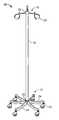
- FIG. 1is a perspective view of an intravenous stand according to one embodiment.
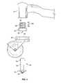
- FIG. 2is an exploded side view illustrating a caster releasably attached to a base of the intravenous stand of FIG. 1 .
- FIG. 3is an exploded side view illustrating a caster releasably attached to a base of the intravenous stand of FIG. 1 according to an alternative embodiment.
- FIG. 4is an exploded side view illustrating a caster releasably attached to a base of the intravenous stand of FIG. 1 according to another alternative embodiment.
- FIG. 5 ais an exploded side view illustrating a caster releasably attached to a base of the intravenous stand of FIG. 1 according to yet another alternative embodiment.
- FIG. 5 bis an exploded side view illustrating a caster releasably attached to a base of the intravenous stand of FIG. 1 according to still another alternative embodiment.
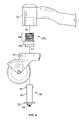
- FIG. 6is a perspective view illustrating the caster of FIG. 2 in an assembled position.
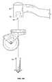
- FIG. 7is an exploded side view illustrating a caster releasably attached to a base of the intravenous stand according to another alternative embodiment.
- FIG. 8is an exploded side view illustrating a caster releasably attached to a base of the intravenous stand according to yet another alternative embodiment.
- FIG. 9is an exploded perspective view of an intravenous stand according to another embodiment.
- FIG. 10is an exploded perspective view illustrating a coupling between an intermediate pole and a lower pole of the intravenous stand of FIG. 9 .
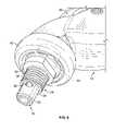
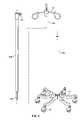
- an intravenous (hereinafter “IV”) stand 10includes a base 12 having a plurality of casters 14 , a pole 16 securely coupled to and extending generally upwardly from the base 12 , and a hanger 18 configured to support one or more intravenous fluid containers (not shown) such as, for example, an IV medication bag.
- the hanger 18may comprise any suitable means for supporting intravenous fluid containers, including, e.g., one or more hooks 20 radially extending from a cap 22 secured to the top end of the pole 16 as shown in FIG. 1 .
- the pole 16may be configured to support additional intravenous equipment (not shown) such as, for example, pumps or monitors.
- the base 12is configured to have a shape, size, and weight that sufficiently stabilizes the IV stand 10 when stationary or during transport.
- the base 12can include six equally spaced base legs 24 extending outwardly from a base hub 26 . It is contemplated that any other number of legs 24 may be provided or any other suitable base 12 configuration may be utilized to stabilize the IV stand 10 .
- the base legs 24can be integrally formed with the base hub 26 or coupled to the base hub 26 by any suitable means such as, for example, welds, bolts, screws, steel casting, extrusion, blow molding, and/or the like.
- each caster 14is releasably coupled to a caster connector 28 a (which is threaded inside a mounting head 32 of the base leg 24 ) via a quick-release member 30 .
- the term “releasably coupled”refers to a state of coupling between two components (e.g., between the quick-release member 30 and the caster connector 28 a ) such that one component (e.g., the quick-release member 30 ) may be quickly removed from or attached to the other component (e.g., the caster connector 28 a ) without the aid of tools, but when attached the components are secured such that simply pulling with force will not uncouple the components.
- the quick-release member 30allows quick and easy replacement of a defective caster 14 , without the use of tools or special expertise.
- a caster 14a caster connector 28 a, and a quick-release member 30 is provided for each of the plurality of base legs 24 .
- the assembly of a single caster 14 , caster connector 28 a, base leg 24 , and quick-release member 30will be described; however, it will be appreciated that the principles described are equally applicable to each caster 14 , each caster connector 28 a, each base leg 24 , and each quick-release member 30 of the IV stand 10 .
- a mounting head 32is located, optionally, at a distal portion of the base leg 24 relative to the base hub 26 .
- the mounting head 32includes a threaded bore 34 into which the caster connector 28 a is coupled.
- the caster connector 28 ais generally tubular with an exteriorly threaded portion 36 at its upper end and a flange portion 38 at its lower end. Accordingly, the threaded portion 36 of the caster connector 28 a is configured to be threadedly engaged with the threaded bore 34 of the mounting head 32 .
- the caster 14includes a wheel 40 and a mounting element 42 .
- the mounting element 42has a mounting aperture 44 therein of a diameter approximately equal to the diameter of an axial aperture 46 within the caster connector 28 a.
- the caster connector 28 aPrior to releasable coupling, the caster connector 28 a is screwed into the threaded bore 34 in the base leg 24 and the mounting aperture 44 in the mounting element 42 of the caster 14 is axially aligned with the axial aperture 46 in the caster connector 28 a.
- the quick-release member 30is generally a quick-release bolt having a stem 50 , a flange portion 52 , a push button 54 , and at least one radially retractable ball 56 that is spring biased to at least partially protrude from the stem 50 .
- the push button 54is spring biased in the released position, causing the retractable ball(s) 56 to at least partially extend from the stem 50 .
- the retractable balls 56retract into the stem 50 .
- the quick-release member 30can be inserted through the mounting element 42 of the caster 14 and into the caster connector 28 a by depressing the push button 54 and thereby causing the retractable balls 56 to retract. A further description of the quick-release member 30 is provided below in reference to FIG. 3 and FIG. 6 .
- the caster connector 28 a and the quick-release member 30may each have a length such that when the quick-release member 30 is fully inserted, the flange portion 52 of the quick-release member 30 is held in contact with a bottom surface of the mounting element 42 . Likewise, a top surface of the mounting element 42 may be held in contact with a bottom surface of the flanged portion 38 of the caster connector 28 a. It is contemplated that the length of each component may be designed to allow sufficiently tight contact such that the casters 14 are firmly supported, yet still permit quick and easy coupling/decoupling of the casters 14 .
- the threaded bore 34 within the mounting head 32has a diameter and depth such that a portion of the quick-release member 30 can extend into the threaded bore 34 beyond an inner lip 58 of the caster connector to permit the retractable balls 56 to extend from the stem 50 .
- a usersimply depresses the push button 54 (to permit the retractable balls 56 to retract inside the stem 50 ) and pulls the caster 14 (along with the quick-release member 30 ) away from the caster connector 28 a and base 12 .
- FIG. 3shows an alternative caster connector 28 b having grooves 62 circumferentially cut into the tubular interior surface 64 of the caster connector 28 b.
- the push button 54is released causing the retractable balls 56 to extend into the grooves 62 .
- the grooves 62can be of sufficient depth and width to allow the retractable balls 56 to extend into the grooves 62 with minimal clearance.
- the grooves 62can be positioned in the caster connector 28 b to allow the retractable balls 56 to extend into the grooves 62 when the quick-release member 30 is fully inserted into the caster connector 28 b such that the flange portion 52 of the quick-release member 30 causes the top surface of the mounting element 42 to be tightly pressed against the flange portion 38 of the caster connector 28 b. Accordingly, if these grooves 62 are included in the caster connector 28 b, it is unnecessary for the bore 34 within the mounting head 32 to allow additional space for a portion of the quick-release member 30 to extend beyond the caster connector 28 b.
- FIG. 4shows a caster connector 28 c having a shape and size that is configured to allow threaded engagement with the threaded bore 34 at an upper end 66 and insertion through the mounting aperture 44 at a lower end 68 .
- the lower end 68can have a diameter and depth such that it may be inserted within the mounting aperture 44 in the mounting element 42 with minimal clearance.
- the threaded portion of the caster connectoris an exteriorly smooth surface, i.e., a threadless surface.
- the caster connectormay be integrally formed or attached to the base by means other than threaded engagement, e.g., welding, adhesive, steel casting, extrusion, blow molding, etc.
- each castermay be connected to the base without a caster connector.
- a groove 70 ( FIG. 5 a ) or an inner lip 72 ( FIG. 5 b )may be provided within the bore 34 of the mounting head 32 and configured to receive the retractable balls 56 as previously described above.
- the quick-release member 30extends axially through the center of the mounting aperture 44 in the mounting element 42 of the caster 14 and into the axial aperture 46 within the caster connector 28 a.
- the quick-release member 30has a diameter that allows the quick-release member 30 to slide into the caster connector 28 a with minimal clearance to maintain a firm coupling and minimize wobbling.
- the quick-release member 30may be any suitable means for coupling a caster 14 to the base 12 such that the caster 14 can be removed from or attached to the base 12 quickly and without the aid of tools. However, the quick-release member 30 must not uncouple simply by pulling the quick-release member 30 from the caster connector 28 a.
- the push button 54is released causing the retractable balls 56 to extend with minimal clearance adjacent an inner lip 58 of the caster connectors 28 a.
- the retractable balls 56radially extend from the stem 50 past the inner lip 58 by a sufficient distance to hold the quick-release member 30 in place.
- any other suitable quick-release membermay be provided.
- the quick-release membermay be square, triangular or octagonal shaped instead of circular or the quick-release member may include a release lever instead of a push button.
- wheelswhich may rotate, but may not swivel to change a direction of movement can be included within or attached to the exterior of the base.
- the quick-release membercan releasably couple a caster to the base in any other suitable configuration.
- the bore 34 in the mounting head 32 illustrated in FIGS. 1-6is substantially perpendicular to a floor surface 78 ; however, it is contemplated that the bore 34 in the mounting head 32 can be angled or parallel to the floor surface 78 as illustrated in FIG. 7 .
- the mounting element 42 of the caster 14can be appropriately modified to permit releasable coupling via a quick-release member 30 inserted through the mounting element 42 and the angled or parallel bore 34 of the mounting head 32 .
- the mounting headcan have two bores instead of one as illustrated in FIG. 8 .
- the first bore 76being substantially perpendicular to the floor surface 78 and the second bore 80 being substantially parallel to the floor surface 78 .
- a caster 14 having a stem 82 extending from the mounting element 42 of the caster 14can be inserted through the first bore 76 and a quick-release member 30 can be inserted through the second bore 80 to releasably couple the caster 14 to the mounting head 32 .
- the quick-release member 30can be inserted through an aperture 84 in the caster stem 82 to releasably couple the caster 14 to the mounting head 32 .
- the IV standmay be made or assembled by providing a hanger that is configured to support one or more intravenous fluid containers, coupling a pole to the hanger at one end of the pole, coupling a base to the other end of the pole, and releasably coupling a plurality of casters to the base via a plurality of quick-release members.
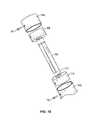
- the pole 16optionally includes an upper member 16 a, an intermediate member 16 b, and a lower member 16 c.
- the top end of the upper member 16 ais secured to the hanger 18 .
- the bottom end of the upper member 16 atelescopes into the intermediate member 16 b and can be locked in a selected height position by a clamping device 64 .
- Any suitable clamping device 64can be provided including, but not limited to, a threaded locking knob mated with a hole tapped through the intermediate member 16 b.
- the height of the upper member 16 acan be adjusted to suit the needs of an individual patient or the upper member 16 a may be easily removed from the intermediate member 16 b and inserted into a socket of a gurney or wheel chair if desired.
- the intermediate member 16 bis coupled to the lower member 16 c via a configuration that prevents relative rotation between the intermediate and lower pole members 16 b, 16 c. This obviates problems often encountered where the intravenous tubing becomes entangled or wrapped around the pole. Additionally, preventing rotation of the intermediate 16 b and lower 16 c members can reduce wear and tear on the IV stand 10 .
- the intermediate member 16 bincludes an insert 66 extending from its bottom end.
- the insert 66can be integrally formed with the intermediate member 16 b or can be a separate member fixedly secured within the intermediate member 16 b. If the insert 66 comprises a separate member, any suitable means may be provided for fixedly securing the insert 66 to the intermediate member 16 b.
- a fitting sleeve 68can be received telescopically in the bottom end of the intermediate member 16 b and fixed therein rigidly by suitable means such as, for example, a cross pin or rivet 70 , which is engaged through registering apertures of the intermediate member 16 b.
- the insert 66can, then, be fixed centrally within the fitting sleeve 68 such that a portion of the insert 66 extends beyond the fitting sleeve 68 .
- the lower member 16 cmay be tubular or otherwise have a centrally located opening 72 at its top end.
- the opening 72is sized and shaped to receive the cross section of the insert 66 such that the insert 66 may be closely slid within the opening 72 with minimal clearance.
- the opening 72may be integrally formed with the top end of the lower member 16 c or the opening 72 may be formed by a receiver sleeve 74 located within the top end of the lower member 16 c.
- the receiver sleeve 74can be fixed concentrically within the top end of the lower member 16 c by suitable means such as, for example, the cross pin 70 .
- the insert 66 and opening 72can each have a length and depth, respectively, to allow the bottom end of the intermediate member 16 b to be flush with the top end of the lower member 16 c.
- the insert 66can be secured within the lower member 16 c by any suitable means.
- a locking pin(not shown) can be received through a radial aperture in the lower pole and an aligned aperture in the insert.
- the insert 66 and the opening 72have non-circular or asymmetric cross sections.
- the insert 66 and the opening 72can be D-shaped (as shown in FIG. 5 ), rectangular, hexagonal, triangular, or the like.
- the insert 66 and the opening 72can be any suitable size.
- the insert 66may be secured to the lower member 16 c and the opening 72 may instead be provided in the intermediate member 16 b.
Landscapes
- Engineering & Computer Science (AREA)
- Mechanical Engineering (AREA)
- Health & Medical Sciences (AREA)
- Hematology (AREA)
- Biomedical Technology (AREA)
- Heart & Thoracic Surgery (AREA)
- Anesthesiology (AREA)
- Life Sciences & Earth Sciences (AREA)
- Animal Behavior & Ethology (AREA)
- General Health & Medical Sciences (AREA)
- Public Health (AREA)
- Veterinary Medicine (AREA)
- Vascular Medicine (AREA)
- Medical Preparation Storing Or Oral Administration Devices (AREA)
- Infusion, Injection, And Reservoir Apparatuses (AREA)
Abstract
Description
Claims (9)
Priority Applications (7)
| Application Number | Priority Date | Filing Date | Title |
|---|---|---|---|
| US12/146,147US8313066B2 (en) | 2008-06-25 | 2008-06-25 | Intravenous fluid container stand and methods for making same |
| CN2009201508932UCN201469763U (en) | 2008-06-25 | 2009-06-24 | Venous fluid container bracket |
| EP12004190.0AEP2510837B1 (en) | 2008-06-25 | 2009-06-25 | Intravenous fluid container stand and methods for making same |
| CA2820141ACA2820141A1 (en) | 2008-06-25 | 2009-06-25 | Intravenous fluid container stand and methods for making same |
| EP09163755AEP2138072B1 (en) | 2008-06-25 | 2009-06-25 | Intravenous fluid container stand and methods for making same |
| CA2670197ACA2670197C (en) | 2008-06-25 | 2009-06-25 | Intravenous fluid container stand and methods for making same |
| US13/655,031US20130037663A1 (en) | 2008-06-25 | 2012-10-18 | Intravenous fluid container stand and methods for making same |
Applications Claiming Priority (1)
| Application Number | Priority Date | Filing Date | Title |
|---|---|---|---|
| US12/146,147US8313066B2 (en) | 2008-06-25 | 2008-06-25 | Intravenous fluid container stand and methods for making same |
Related Child Applications (1)
| Application Number | Title | Priority Date | Filing Date |
|---|---|---|---|
| US13/655,031DivisionUS20130037663A1 (en) | 2008-06-25 | 2012-10-18 | Intravenous fluid container stand and methods for making same |
Publications (2)
| Publication Number | Publication Date |
|---|---|
| US20090321589A1 US20090321589A1 (en) | 2009-12-31 |
| US8313066B2true US8313066B2 (en) | 2012-11-20 |
Family
ID=41128047
Family Applications (2)
| Application Number | Title | Priority Date | Filing Date |
|---|---|---|---|
| US12/146,147Active2030-12-29US8313066B2 (en) | 2008-06-25 | 2008-06-25 | Intravenous fluid container stand and methods for making same |
| US13/655,031AbandonedUS20130037663A1 (en) | 2008-06-25 | 2012-10-18 | Intravenous fluid container stand and methods for making same |
Family Applications After (1)
| Application Number | Title | Priority Date | Filing Date |
|---|---|---|---|
| US13/655,031AbandonedUS20130037663A1 (en) | 2008-06-25 | 2012-10-18 | Intravenous fluid container stand and methods for making same |
Country Status (4)
| Country | Link |
|---|---|
| US (2) | US8313066B2 (en) |
| EP (2) | EP2510837B1 (en) |
| CN (1) | CN201469763U (en) |
| CA (2) | CA2820141A1 (en) |
Cited By (22)
| Publication number | Priority date | Publication date | Assignee | Title |
|---|---|---|---|---|
| US20130125378A1 (en)* | 2011-11-23 | 2013-05-23 | Emily Hannah Berman | Leg Rest Release Assembly and Method of Assembling the Same |
| US20150048582A1 (en)* | 2010-10-29 | 2015-02-19 | Evolution Technologies Inc. | Foldable walker apparatus |
| US20150139724A1 (en)* | 2013-11-21 | 2015-05-21 | Carpin Manufacturing, Inc. | Socket Assembly |
| USD734541S1 (en)* | 2013-05-15 | 2015-07-14 | P.S. Pibbs, Inc. | Wheeled pedestal for holding hair styling tools |
| US9320672B2 (en) | 2010-10-29 | 2016-04-26 | Evolution Technolgies Inc. | Foldable walker apparatus |
| US9339432B2 (en) | 2014-02-28 | 2016-05-17 | Evolution Technologies Inc. | Walker apparatus and backrest therefor |
| US9375626B2 (en)* | 2014-05-09 | 2016-06-28 | Steven E. English | Rotatable weight tree |
| US9523381B1 (en) | 2013-11-21 | 2016-12-20 | Carpin Manufacturing, Inc. | Socket assembly |
| US9623888B2 (en) | 2008-10-08 | 2017-04-18 | Evolution Technologies Inc. | Foldable walker apparatus |
| US9744094B2 (en) | 2014-02-28 | 2017-08-29 | Evolution Technologies Inc. | Walker apparatus and backrest therefor |
| USD820977S1 (en)* | 2016-11-21 | 2018-06-19 | Samsung Electronics Co., Ltd. | Medical stand |
| US10053062B2 (en) | 2015-09-02 | 2018-08-21 | Evolution Technologies Inc. | Brake assembly for a height-adjustable walker apparatus |
| US10060571B2 (en)* | 2016-06-21 | 2018-08-28 | Pedigo Products, Inc. | Hook attachment for mobile stand for use with intravenous delivery of medications |
| USD828701S1 (en) | 2017-02-17 | 2018-09-18 | Evolution Technologies Inc. | Set of seat cushions |
| US10582981B2 (en) | 2016-02-02 | 2020-03-10 | Stryker Corporation | Accessory support and coupling systems for an accessory support |
| USD880802S1 (en)* | 2018-03-16 | 2020-04-07 | EchoNous, Inc. | Locking collar for a cart |
| USD884883S1 (en)* | 2018-03-16 | 2020-05-19 | Pedigo Products, Inc. | Wheeled stand |
| USD886494S1 (en) | 2016-02-26 | 2020-06-09 | Evolution Technologies Inc. | Set of seat cushions |
| US10730489B2 (en) | 2015-09-02 | 2020-08-04 | Evolution Technologies Inc. | Brake assembly for height-adjustable patient transport apparatus |
| US11007102B2 (en) | 2017-08-22 | 2021-05-18 | Stryker Corporation | Patient transport system |
| US11648922B2 (en) | 2015-09-02 | 2023-05-16 | Evolution Technologies Inc. | Manually-operated, height-adjustable wheeled vehicle, and a brake assembly and wheel fork assembly thereof |
| USD1034973S1 (en)* | 2022-03-11 | 2024-07-09 | Yajun Hu | IV pole |
Families Citing this family (13)
| Publication number | Priority date | Publication date | Assignee | Title |
|---|---|---|---|---|
| US8196874B2 (en)* | 2007-10-12 | 2012-06-12 | Maxtec, Llc | Storable intravenous stands |
| US8398038B2 (en)* | 2009-11-30 | 2013-03-19 | The United States Of America As Represented By The Secretary Of The Navy | Wheel support |
| SE538856C2 (en)* | 2012-01-10 | 2017-01-03 | Tarsus Products Ab | System for storing collapsible infusion sets |
| US9707334B2 (en) | 2013-03-15 | 2017-07-18 | Skytron, Llc | Transformable intravenous pole and boom combination and method thereof |
| US20150113766A1 (en)* | 2013-10-24 | 2015-04-30 | I-shun Hou | Roller wheel for luggage |
| KR101674385B1 (en)* | 2014-12-01 | 2016-11-09 | 김창영 | Hanger for ringer |
| USD804039S1 (en)* | 2016-05-02 | 2017-11-28 | Stryker Corporation | Base for medical accessory |
| USD848003S1 (en)* | 2017-04-07 | 2019-05-07 | Norman Charles Worcester | Medical equipment stand |
| US10154885B1 (en) | 2017-05-26 | 2018-12-18 | Medline Industries, Inc. | Systems, apparatus and methods for continuously tracking medical items throughout a procedure |
| CN107773805A (en)* | 2017-10-22 | 2018-03-09 | 王伟 | A kind of medical infusion aircraft |
| US11617625B2 (en) | 2019-03-12 | 2023-04-04 | Medline Industries, Lp | Systems, apparatus and methods for properly locating items |
| US12059276B2 (en) | 2019-08-21 | 2024-08-13 | Medline Industries, Lp | Systems, apparatus and methods for automatically counting medical objects, estimating blood loss and/or communicating between medical equipment |
| US20240016686A1 (en)* | 2022-07-13 | 2024-01-18 | Dominion Investments LLC | Medical cart for use in patient care |
Citations (92)
| Publication number | Priority date | Publication date | Assignee | Title |
|---|---|---|---|---|
| US2313883A (en)* | 1942-04-17 | 1943-03-16 | William P Lowther | Sheet metal clamp |
| US2350630A (en)* | 1942-08-04 | 1944-06-06 | Francis L Smith | Sheet holding tool |
| US2373083A (en)* | 1943-10-29 | 1945-04-03 | Boeing Aircraft Co | Fastening device |
| US2393587A (en)* | 1943-11-01 | 1946-01-29 | Bugg | Temporary fastener |
| US2902592A (en) | 1957-07-05 | 1959-09-01 | Rex Cole Inc | Portable lamp |
| US2957187A (en) | 1958-06-06 | 1960-10-25 | Wilmette Screw Products | Telescopic stand |
| US3117484A (en)* | 1958-11-17 | 1964-01-14 | Aerpat Ag | Movable detent fastener for variable thickness work |
| US3183586A (en)* | 1959-04-27 | 1965-05-18 | Aerpat Ag | Method of making fastening devices |
| US3486185A (en)* | 1967-03-27 | 1969-12-30 | Gerhard Lange | Caster cover |
| US3596554A (en)* | 1970-05-19 | 1971-08-03 | Nasa | Safety-type locking pin |
| US3709556A (en) | 1970-10-16 | 1973-01-09 | E Allard | Telescoping i v pole attachment and wheel chairs |
| US3752493A (en) | 1971-01-25 | 1973-08-14 | H Mcwhorter | Retractable and detachable wheel assembly |
| US4190224A (en) | 1977-04-25 | 1980-02-26 | Leblanc Edgar J | Intravenous pole holder |
| USD264379S (en) | 1980-02-11 | 1982-05-11 | Raymond Slinkard | Adjustable, detachable handle suitable for use on wheeled, hospital-type IV stands and the like |
| US4392690A (en) | 1981-03-09 | 1983-07-12 | Anderson Raymond A | Quick release wheel mount |
| US4477121A (en) | 1982-09-30 | 1984-10-16 | Atkins Michael T | Quick release wheel |
| US4511158A (en) | 1982-08-27 | 1985-04-16 | Mt. Sinai Medical Center Of Greater Miami | Intravenous infusion pole attachment |
| US4511157A (en) | 1982-07-19 | 1985-04-16 | St. Joseph's Hospital And Medical Center | Apparatus for facilitating intravenous feeding during transportation of patient |
| US4541596A (en) | 1982-09-13 | 1985-09-17 | Price Ronald K | Portable intravenous pole for use in an emergency |
| US4572536A (en) | 1983-05-26 | 1986-02-25 | Doughty Val J | I V Pole interconnection coupling |
| US4582448A (en) | 1981-06-06 | 1986-04-15 | Costello William D | Releasable wheel axle device |
| WO1987002754A1 (en) | 1985-11-01 | 1987-05-07 | Vaughan Thomas L | Support assembly |
| US4666111A (en) | 1985-11-14 | 1987-05-19 | Robert Schuler | Holder for IV tube |
| US4681495A (en)* | 1983-10-23 | 1987-07-21 | Framatome & Cie | Device and process for fixing two parts with a captive screw |
| US4719663A (en) | 1986-08-29 | 1988-01-19 | Marvel Metal Products Company | Detachable caster wheel assembly having a flange and bolt mechanism |
| US4725027A (en) | 1986-09-23 | 1988-02-16 | Joseph Bekanich | Intravenous equipment support |
| US4788741A (en)* | 1987-07-17 | 1988-12-06 | Hilborn Robert R | Keyed mounting assembly for lockable swivel caster |
| US4805941A (en) | 1985-06-10 | 1989-02-21 | Huffy Corporation | Quick release wheel retainer |
| US4832294A (en) | 1986-06-17 | 1989-05-23 | Demstar Corporation | Portable I.V. stand |
| US4901980A (en) | 1987-04-29 | 1990-02-20 | Johnson Industries, Inc. | Portable car hoist and trailer with removable wheels |
| US4966340A (en) | 1989-04-24 | 1990-10-30 | Hunter Rebecca L | Wheeled stand apparatus for hanging containers of medical fluids |
| US4969768A (en) | 1989-09-28 | 1990-11-13 | Young Robert J | Coupler for IV pole |
| US5083807A (en) | 1990-12-18 | 1992-01-28 | Church Home & Hospital Of The City Of Baltimore | IV stand coupling device |
| US5094418A (en) | 1990-09-07 | 1992-03-10 | Stryker Corporation | IV pole |
| US5112019A (en) | 1991-02-04 | 1992-05-12 | Storz Instrument Company | Motorized IV pole assembly |
| US5135191A (en) | 1991-05-09 | 1992-08-04 | Jagco Corporation | Medical support system |
| US5149036A (en) | 1991-08-29 | 1992-09-22 | Sheehan Gerald F | Device for attaching an IV pole to a hospital bed or the like |
| US5219139A (en) | 1992-06-25 | 1993-06-15 | Barnes Hospital | Device for connecting an IV pole to a wheelchair |
| US5230496A (en) | 1991-08-06 | 1993-07-27 | Med-Safe Systems, Inc. | Pole mounting clamp |
| US5236213A (en) | 1991-02-12 | 1993-08-17 | Trickett James R | IV utility pole coupling and towing device |
| US5344169A (en) | 1992-01-27 | 1994-09-06 | Pryor Products | Multi-pole support stand |
| US5347681A (en) | 1993-02-03 | 1994-09-20 | James P. Wattron | Releasable fifth wheel caster for skateboards |
| US5355539A (en) | 1993-01-19 | 1994-10-18 | St. Francis Research Institute | Clamp for interconnecting a free standing, wheeled intravenous pole with a mobile gurney |
| US5358205A (en) | 1993-04-16 | 1994-10-25 | Starkey Douglas G | Device to connect I.V. pole and patient support |
| US5374074A (en) | 1993-06-25 | 1994-12-20 | Smith; Sidney | Apparatus for attaching intravenous infusion poles to foldable wheelchairs |
| US5458305A (en) | 1993-05-17 | 1995-10-17 | Woodward; John | Portable intravenous support stand |
| US5476275A (en) | 1992-09-18 | 1995-12-19 | Racing Strollers, Inc. | Baby stroller with removable wheels |
| US5551105A (en) | 1994-08-26 | 1996-09-03 | Brevis Corporation | Apparatus combining overbed table, IV stand, walker, and seat |
| US5594974A (en) | 1993-02-03 | 1997-01-21 | James P. Wattron | Releasable caster |
| US5704577A (en) | 1995-10-11 | 1998-01-06 | Gordon; Gray J. | Walker-IV stand coupler |
| US5727850A (en)* | 1995-05-19 | 1998-03-17 | Masclet; Claude | Safety and control system for the locking mechanism of a wheel hub, notably for wheelchairs |
| US5740584A (en) | 1996-08-12 | 1998-04-21 | Hodge Products, Inc. | Releasable caster holder |
| US5742977A (en)* | 1991-11-10 | 1998-04-28 | Hoofe, Iii; William J. | Wheels for restaurant and industrial equipment and shelving |
| US5772162A (en) | 1996-10-16 | 1998-06-30 | Lin; Chin-Liang | Drop-bottle stand |
| US5776105A (en) | 1995-09-28 | 1998-07-07 | Children's Medical Center Corp. | Ambulatory intravenous fluid holder |
| US5820086A (en) | 1992-02-28 | 1998-10-13 | Hoftman; Mike M. | I.V. pole and irrigation tower and support system |
| US5857685A (en) | 1995-08-09 | 1999-01-12 | Phillips; James R. | Support cart apparatus for supporting intravenous fluid dispensing systems |
| US5924658A (en) | 1998-01-07 | 1999-07-20 | Stryker Corporation | IV pole |
| US6079678A (en) | 1998-10-22 | 2000-06-27 | Schott; Jeffery C. | Intravenous stand support assembly |
| US6182662B1 (en) | 1998-07-23 | 2001-02-06 | Mcghee Chad J. | Intravenous transport/support device |
| US6193323B1 (en) | 1999-07-21 | 2001-02-27 | Hui-Liang Lin | Hidden type quick-release wheel hub assembly with reinforcing arrangement |
| US6253891B1 (en) | 1999-08-16 | 2001-07-03 | Travelpro International, Inc. | Removable wheel system |
| US6267452B1 (en) | 1999-07-21 | 2001-07-31 | Hui-Liang Lin | Hidden type quick-release wheel hub assembly with reinforcing arrangement |
| US6279926B1 (en) | 1999-08-25 | 2001-08-28 | Tranzporter International Llc | Removable wheel system |
| WO2002009632A2 (en) | 2000-08-01 | 2002-02-07 | Hill-Rom Services, Inc. | Medical device support assembly |
| US20020038843A1 (en) | 2000-09-29 | 2002-04-04 | Formway Furniture Limited | Castored base for an office chair |
| US6375133B1 (en) | 1998-03-04 | 2002-04-23 | Emergent Innovations, Llc. | Intravenous (IV) pole for transport with multiple infusion devices |
| US6386789B1 (en)* | 1999-09-24 | 2002-05-14 | Paul D. Chausse | Quick release ball type locking pin and production tool |
| US6390311B1 (en) | 2000-07-31 | 2002-05-21 | Martin Paul, Inc. | Ambulatory dispenser rack |
| US20020096608A1 (en) | 2001-01-19 | 2002-07-25 | Cedarberg Industries, Inc. | IV stand cord/tube holder |
| US20020104934A1 (en) | 1998-03-04 | 2002-08-08 | Emergent Innovations, Llc | Intravenous (IV) pole supporting systems |
| US6634665B2 (en) | 2001-08-03 | 2003-10-21 | Todd L. Hargroder | Quick release detachable wheels |
| US6708991B1 (en) | 2002-07-05 | 2004-03-23 | Art Ortlieb | Ambulatory IV dolly |
| US6722711B2 (en)* | 2002-04-09 | 2004-04-20 | Roger S. Kitzis | Anti-animal container lock |
| US6796001B1 (en)* | 2002-07-31 | 2004-09-28 | Kason Industries, Inc. | Height adjustable support for food service equipment |
| US6810561B1 (en)* | 2003-04-15 | 2004-11-02 | Taiwan Ultra Power Industries Ltd. | On a wheel of a rack |
| US20050116126A1 (en) | 2003-12-02 | 2005-06-02 | Ugent Cari L. | IV pole |
| US7011321B2 (en) | 2002-05-23 | 2006-03-14 | Hargroder Todd L | Quick release detachable wheels |
| US20070023587A1 (en) | 2003-12-15 | 2007-02-01 | Eggleston Gray J | I. v. support stand and clamp apparatus |
| US7207532B1 (en) | 2003-10-09 | 2007-04-24 | Roberts Jeffrey A | Boom stand |
| US20070176063A1 (en) | 2006-01-19 | 2007-08-02 | Hill-Rom Services, Inc. | Patient support with mobile iv stand transport handle |
| US20070221796A1 (en) | 2006-03-25 | 2007-09-27 | Silverman Jeffrey M | Infusion stand |
| US7281691B2 (en) | 2003-04-17 | 2007-10-16 | Adelman Gregg Z | Transportable intravenous bag stand |
| US20070267550A1 (en) | 2006-02-27 | 2007-11-22 | Peter Blankenship | Transformable intravenous pole |
| US20070267551A1 (en) | 2006-05-19 | 2007-11-22 | Joseph Gordon Townsend | IV Pole Caddy |
| US7314200B2 (en) | 2004-05-13 | 2008-01-01 | American Sterilizer Company | Support and transport system for medical apparatus |
| US20080011907A1 (en) | 2006-07-13 | 2008-01-17 | Jacobsma Paul M | Intravenous line organizer |
| US20080054132A1 (en) | 2006-09-05 | 2008-03-06 | Cindy Muncie | Intravenous Fluid Container Stand |
| US7431531B2 (en)* | 2006-03-30 | 2008-10-07 | Carnevali Jeffrey D | Quick release mounting apparatus |
| US7552508B2 (en)* | 2006-05-17 | 2009-06-30 | Alcon, Inc. | Caster attachment system |
| US7594874B2 (en)* | 2006-04-12 | 2009-09-29 | Meissner Richard K | Quick connect climbing hold |
| US7731465B2 (en)* | 2005-07-01 | 2010-06-08 | Jergens, Inc. | Release pin |
- 2008
- 2008-06-25USUS12/146,147patent/US8313066B2/enactiveActive
- 2009
- 2009-06-24CNCN2009201508932Upatent/CN201469763U/ennot_activeExpired - Lifetime
- 2009-06-25CACA2820141Apatent/CA2820141A1/ennot_activeAbandoned
- 2009-06-25EPEP12004190.0Apatent/EP2510837B1/enactiveActive
- 2009-06-25CACA2670197Apatent/CA2670197C/enactiveActive
- 2009-06-25EPEP09163755Apatent/EP2138072B1/enactiveActive
- 2012
- 2012-10-18USUS13/655,031patent/US20130037663A1/ennot_activeAbandoned
Patent Citations (95)
| Publication number | Priority date | Publication date | Assignee | Title |
|---|---|---|---|---|
| US2313883A (en)* | 1942-04-17 | 1943-03-16 | William P Lowther | Sheet metal clamp |
| US2350630A (en)* | 1942-08-04 | 1944-06-06 | Francis L Smith | Sheet holding tool |
| US2373083A (en)* | 1943-10-29 | 1945-04-03 | Boeing Aircraft Co | Fastening device |
| US2393587A (en)* | 1943-11-01 | 1946-01-29 | Bugg | Temporary fastener |
| US2902592A (en) | 1957-07-05 | 1959-09-01 | Rex Cole Inc | Portable lamp |
| US2957187A (en) | 1958-06-06 | 1960-10-25 | Wilmette Screw Products | Telescopic stand |
| US3117484A (en)* | 1958-11-17 | 1964-01-14 | Aerpat Ag | Movable detent fastener for variable thickness work |
| US3183586A (en)* | 1959-04-27 | 1965-05-18 | Aerpat Ag | Method of making fastening devices |
| US3486185A (en)* | 1967-03-27 | 1969-12-30 | Gerhard Lange | Caster cover |
| US3596554A (en)* | 1970-05-19 | 1971-08-03 | Nasa | Safety-type locking pin |
| US3709556A (en) | 1970-10-16 | 1973-01-09 | E Allard | Telescoping i v pole attachment and wheel chairs |
| US3752493A (en) | 1971-01-25 | 1973-08-14 | H Mcwhorter | Retractable and detachable wheel assembly |
| US4190224A (en) | 1977-04-25 | 1980-02-26 | Leblanc Edgar J | Intravenous pole holder |
| USD264379S (en) | 1980-02-11 | 1982-05-11 | Raymond Slinkard | Adjustable, detachable handle suitable for use on wheeled, hospital-type IV stands and the like |
| US4392690A (en) | 1981-03-09 | 1983-07-12 | Anderson Raymond A | Quick release wheel mount |
| US4582448A (en) | 1981-06-06 | 1986-04-15 | Costello William D | Releasable wheel axle device |
| US4511157A (en) | 1982-07-19 | 1985-04-16 | St. Joseph's Hospital And Medical Center | Apparatus for facilitating intravenous feeding during transportation of patient |
| US4511158A (en) | 1982-08-27 | 1985-04-16 | Mt. Sinai Medical Center Of Greater Miami | Intravenous infusion pole attachment |
| US4541596A (en) | 1982-09-13 | 1985-09-17 | Price Ronald K | Portable intravenous pole for use in an emergency |
| US4477121A (en) | 1982-09-30 | 1984-10-16 | Atkins Michael T | Quick release wheel |
| US4572536A (en) | 1983-05-26 | 1986-02-25 | Doughty Val J | I V Pole interconnection coupling |
| US4681495A (en)* | 1983-10-23 | 1987-07-21 | Framatome & Cie | Device and process for fixing two parts with a captive screw |
| US4805941A (en) | 1985-06-10 | 1989-02-21 | Huffy Corporation | Quick release wheel retainer |
| WO1987002754A1 (en) | 1985-11-01 | 1987-05-07 | Vaughan Thomas L | Support assembly |
| US4666111A (en) | 1985-11-14 | 1987-05-19 | Robert Schuler | Holder for IV tube |
| US4832294A (en) | 1986-06-17 | 1989-05-23 | Demstar Corporation | Portable I.V. stand |
| US4719663A (en) | 1986-08-29 | 1988-01-19 | Marvel Metal Products Company | Detachable caster wheel assembly having a flange and bolt mechanism |
| US4725027A (en) | 1986-09-23 | 1988-02-16 | Joseph Bekanich | Intravenous equipment support |
| US4901980A (en) | 1987-04-29 | 1990-02-20 | Johnson Industries, Inc. | Portable car hoist and trailer with removable wheels |
| US4788741A (en)* | 1987-07-17 | 1988-12-06 | Hilborn Robert R | Keyed mounting assembly for lockable swivel caster |
| US4966340A (en) | 1989-04-24 | 1990-10-30 | Hunter Rebecca L | Wheeled stand apparatus for hanging containers of medical fluids |
| US4969768A (en) | 1989-09-28 | 1990-11-13 | Young Robert J | Coupler for IV pole |
| US5094418A (en) | 1990-09-07 | 1992-03-10 | Stryker Corporation | IV pole |
| US5083807A (en) | 1990-12-18 | 1992-01-28 | Church Home & Hospital Of The City Of Baltimore | IV stand coupling device |
| US5112019A (en) | 1991-02-04 | 1992-05-12 | Storz Instrument Company | Motorized IV pole assembly |
| US5236213A (en) | 1991-02-12 | 1993-08-17 | Trickett James R | IV utility pole coupling and towing device |
| US5135191A (en) | 1991-05-09 | 1992-08-04 | Jagco Corporation | Medical support system |
| US5230496A (en) | 1991-08-06 | 1993-07-27 | Med-Safe Systems, Inc. | Pole mounting clamp |
| US5149036A (en) | 1991-08-29 | 1992-09-22 | Sheehan Gerald F | Device for attaching an IV pole to a hospital bed or the like |
| US5742977A (en)* | 1991-11-10 | 1998-04-28 | Hoofe, Iii; William J. | Wheels for restaurant and industrial equipment and shelving |
| US5344169A (en) | 1992-01-27 | 1994-09-06 | Pryor Products | Multi-pole support stand |
| US5820086A (en) | 1992-02-28 | 1998-10-13 | Hoftman; Mike M. | I.V. pole and irrigation tower and support system |
| US5219139A (en) | 1992-06-25 | 1993-06-15 | Barnes Hospital | Device for connecting an IV pole to a wheelchair |
| US5476275A (en) | 1992-09-18 | 1995-12-19 | Racing Strollers, Inc. | Baby stroller with removable wheels |
| US5355539A (en) | 1993-01-19 | 1994-10-18 | St. Francis Research Institute | Clamp for interconnecting a free standing, wheeled intravenous pole with a mobile gurney |
| US5699988A (en) | 1993-01-19 | 1997-12-23 | St. Francis Research Institute | Coupler clamping apparatus for interconnecting a free-standing, wheeled intravenous pole with mobile patient transfer devices |
| US5347681A (en) | 1993-02-03 | 1994-09-20 | James P. Wattron | Releasable fifth wheel caster for skateboards |
| US5594974A (en) | 1993-02-03 | 1997-01-21 | James P. Wattron | Releasable caster |
| US5358205A (en) | 1993-04-16 | 1994-10-25 | Starkey Douglas G | Device to connect I.V. pole and patient support |
| US5458305A (en) | 1993-05-17 | 1995-10-17 | Woodward; John | Portable intravenous support stand |
| US5374074A (en) | 1993-06-25 | 1994-12-20 | Smith; Sidney | Apparatus for attaching intravenous infusion poles to foldable wheelchairs |
| US5551105A (en) | 1994-08-26 | 1996-09-03 | Brevis Corporation | Apparatus combining overbed table, IV stand, walker, and seat |
| US5727850A (en)* | 1995-05-19 | 1998-03-17 | Masclet; Claude | Safety and control system for the locking mechanism of a wheel hub, notably for wheelchairs |
| US5857685A (en) | 1995-08-09 | 1999-01-12 | Phillips; James R. | Support cart apparatus for supporting intravenous fluid dispensing systems |
| US5776105A (en) | 1995-09-28 | 1998-07-07 | Children's Medical Center Corp. | Ambulatory intravenous fluid holder |
| US5704577A (en) | 1995-10-11 | 1998-01-06 | Gordon; Gray J. | Walker-IV stand coupler |
| US5740584A (en) | 1996-08-12 | 1998-04-21 | Hodge Products, Inc. | Releasable caster holder |
| US5772162A (en) | 1996-10-16 | 1998-06-30 | Lin; Chin-Liang | Drop-bottle stand |
| US5924658A (en) | 1998-01-07 | 1999-07-20 | Stryker Corporation | IV pole |
| US6375133B1 (en) | 1998-03-04 | 2002-04-23 | Emergent Innovations, Llc. | Intravenous (IV) pole for transport with multiple infusion devices |
| US6619599B2 (en) | 1998-03-04 | 2003-09-16 | Emergent Innovations, Llc | Intravenous (IV) pole supporting systems |
| US20020104934A1 (en) | 1998-03-04 | 2002-08-08 | Emergent Innovations, Llc | Intravenous (IV) pole supporting systems |
| US6182662B1 (en) | 1998-07-23 | 2001-02-06 | Mcghee Chad J. | Intravenous transport/support device |
| US6079678A (en) | 1998-10-22 | 2000-06-27 | Schott; Jeffery C. | Intravenous stand support assembly |
| US6193323B1 (en) | 1999-07-21 | 2001-02-27 | Hui-Liang Lin | Hidden type quick-release wheel hub assembly with reinforcing arrangement |
| US6267452B1 (en) | 1999-07-21 | 2001-07-31 | Hui-Liang Lin | Hidden type quick-release wheel hub assembly with reinforcing arrangement |
| US6253891B1 (en) | 1999-08-16 | 2001-07-03 | Travelpro International, Inc. | Removable wheel system |
| US6279926B1 (en) | 1999-08-25 | 2001-08-28 | Tranzporter International Llc | Removable wheel system |
| US6386789B1 (en)* | 1999-09-24 | 2002-05-14 | Paul D. Chausse | Quick release ball type locking pin and production tool |
| US6390311B1 (en) | 2000-07-31 | 2002-05-21 | Martin Paul, Inc. | Ambulatory dispenser rack |
| WO2002009632A2 (en) | 2000-08-01 | 2002-02-07 | Hill-Rom Services, Inc. | Medical device support assembly |
| US20020038843A1 (en) | 2000-09-29 | 2002-04-04 | Formway Furniture Limited | Castored base for an office chair |
| US20020096608A1 (en) | 2001-01-19 | 2002-07-25 | Cedarberg Industries, Inc. | IV stand cord/tube holder |
| US6634665B2 (en) | 2001-08-03 | 2003-10-21 | Todd L. Hargroder | Quick release detachable wheels |
| US6722711B2 (en)* | 2002-04-09 | 2004-04-20 | Roger S. Kitzis | Anti-animal container lock |
| US7011321B2 (en) | 2002-05-23 | 2006-03-14 | Hargroder Todd L | Quick release detachable wheels |
| US6708991B1 (en) | 2002-07-05 | 2004-03-23 | Art Ortlieb | Ambulatory IV dolly |
| US6796001B1 (en)* | 2002-07-31 | 2004-09-28 | Kason Industries, Inc. | Height adjustable support for food service equipment |
| US6810561B1 (en)* | 2003-04-15 | 2004-11-02 | Taiwan Ultra Power Industries Ltd. | On a wheel of a rack |
| US7281691B2 (en) | 2003-04-17 | 2007-10-16 | Adelman Gregg Z | Transportable intravenous bag stand |
| US7207532B1 (en) | 2003-10-09 | 2007-04-24 | Roberts Jeffrey A | Boom stand |
| US6969031B2 (en) | 2003-12-02 | 2005-11-29 | Cari Lynn Ugent | Adjustable movable IV stand |
| US20050116126A1 (en) | 2003-12-02 | 2005-06-02 | Ugent Cari L. | IV pole |
| US20070023587A1 (en) | 2003-12-15 | 2007-02-01 | Eggleston Gray J | I. v. support stand and clamp apparatus |
| US7314200B2 (en) | 2004-05-13 | 2008-01-01 | American Sterilizer Company | Support and transport system for medical apparatus |
| US7731465B2 (en)* | 2005-07-01 | 2010-06-08 | Jergens, Inc. | Release pin |
| US20070176063A1 (en) | 2006-01-19 | 2007-08-02 | Hill-Rom Services, Inc. | Patient support with mobile iv stand transport handle |
| US20070267550A1 (en) | 2006-02-27 | 2007-11-22 | Peter Blankenship | Transformable intravenous pole |
| US20070221796A1 (en) | 2006-03-25 | 2007-09-27 | Silverman Jeffrey M | Infusion stand |
| US7431531B2 (en)* | 2006-03-30 | 2008-10-07 | Carnevali Jeffrey D | Quick release mounting apparatus |
| US7594874B2 (en)* | 2006-04-12 | 2009-09-29 | Meissner Richard K | Quick connect climbing hold |
| US7552508B2 (en)* | 2006-05-17 | 2009-06-30 | Alcon, Inc. | Caster attachment system |
| US20070267551A1 (en) | 2006-05-19 | 2007-11-22 | Joseph Gordon Townsend | IV Pole Caddy |
| US20080011907A1 (en) | 2006-07-13 | 2008-01-17 | Jacobsma Paul M | Intravenous line organizer |
| US20080054132A1 (en) | 2006-09-05 | 2008-03-06 | Cindy Muncie | Intravenous Fluid Container Stand |
Non-Patent Citations (3)
| Title |
|---|
| Darcor "Innovators in Motion Technology Catalogue 2000", pp. 45-47, electronically available at http://www.darcor.com/public/File/pdf/Darcor-Casters-Product-Catalogue.PDF (last visited Sep. 19, 2008). |
| Extended European Search Report corresponding to co-pending European Patent Application Serial No. 09163755.3, European Patent Office, Feb. 18, 2010; 11 pages. |
| Partial European Search Report corresponding to co-pending European Patent Application Serial No. 09163755.3, European Patent Office, Oct. 26, 2009; 5 pages. |
Cited By (29)
| Publication number | Priority date | Publication date | Assignee | Title |
|---|---|---|---|---|
| US9623888B2 (en) | 2008-10-08 | 2017-04-18 | Evolution Technologies Inc. | Foldable walker apparatus |
| US9415635B2 (en)* | 2010-10-29 | 2016-08-16 | Evolution Technologies Inc. | Foldable walker apparatus |
| US20150048582A1 (en)* | 2010-10-29 | 2015-02-19 | Evolution Technologies Inc. | Foldable walker apparatus |
| US9320672B2 (en) | 2010-10-29 | 2016-04-26 | Evolution Technolgies Inc. | Foldable walker apparatus |
| US20130125378A1 (en)* | 2011-11-23 | 2013-05-23 | Emily Hannah Berman | Leg Rest Release Assembly and Method of Assembling the Same |
| USD734541S1 (en)* | 2013-05-15 | 2015-07-14 | P.S. Pibbs, Inc. | Wheeled pedestal for holding hair styling tools |
| US9428008B2 (en)* | 2013-11-21 | 2016-08-30 | Carpin Manufacturing, Inc. | Socket assembly |
| US9523381B1 (en) | 2013-11-21 | 2016-12-20 | Carpin Manufacturing, Inc. | Socket assembly |
| US20150139724A1 (en)* | 2013-11-21 | 2015-05-21 | Carpin Manufacturing, Inc. | Socket Assembly |
| US9339432B2 (en) | 2014-02-28 | 2016-05-17 | Evolution Technologies Inc. | Walker apparatus and backrest therefor |
| US9744094B2 (en) | 2014-02-28 | 2017-08-29 | Evolution Technologies Inc. | Walker apparatus and backrest therefor |
| US9375626B2 (en)* | 2014-05-09 | 2016-06-28 | Steven E. English | Rotatable weight tree |
| US11648922B2 (en) | 2015-09-02 | 2023-05-16 | Evolution Technologies Inc. | Manually-operated, height-adjustable wheeled vehicle, and a brake assembly and wheel fork assembly thereof |
| US10053062B2 (en) | 2015-09-02 | 2018-08-21 | Evolution Technologies Inc. | Brake assembly for a height-adjustable walker apparatus |
| US11220246B2 (en) | 2015-09-02 | 2022-01-11 | Evolution Technologies Inc. | Brake assembly for height-adjustable patient transport apparatus |
| US10730489B2 (en) | 2015-09-02 | 2020-08-04 | Evolution Technologies Inc. | Brake assembly for height-adjustable patient transport apparatus |
| US11540891B2 (en) | 2016-02-02 | 2023-01-03 | Stryker Corporation | Accessory support and coupling systems for an accessory support |
| US11000340B2 (en) | 2016-02-02 | 2021-05-11 | Stryker Corporation | Accessory support and coupling systems for an accessory support |
| US10582981B2 (en) | 2016-02-02 | 2020-03-10 | Stryker Corporation | Accessory support and coupling systems for an accessory support |
| USD886494S1 (en) | 2016-02-26 | 2020-06-09 | Evolution Technologies Inc. | Set of seat cushions |
| US10426887B2 (en)* | 2016-06-21 | 2019-10-01 | Pedigo Products, Inc. | Handle for mobile stand for use with intravenous delivery of medications |
| US10369273B2 (en)* | 2016-06-21 | 2019-08-06 | Pedigo Products, Inc. | Interlocking base for mobile stand for use with intravenous delivery of medications |
| US10060571B2 (en)* | 2016-06-21 | 2018-08-28 | Pedigo Products, Inc. | Hook attachment for mobile stand for use with intravenous delivery of medications |
| USD820977S1 (en)* | 2016-11-21 | 2018-06-19 | Samsung Electronics Co., Ltd. | Medical stand |
| USD828701S1 (en) | 2017-02-17 | 2018-09-18 | Evolution Technologies Inc. | Set of seat cushions |
| US11007102B2 (en) | 2017-08-22 | 2021-05-18 | Stryker Corporation | Patient transport system |
| USD884883S1 (en)* | 2018-03-16 | 2020-05-19 | Pedigo Products, Inc. | Wheeled stand |
| USD880802S1 (en)* | 2018-03-16 | 2020-04-07 | EchoNous, Inc. | Locking collar for a cart |
| USD1034973S1 (en)* | 2022-03-11 | 2024-07-09 | Yajun Hu | IV pole |
Also Published As
| Publication number | Publication date |
|---|---|
| US20130037663A1 (en) | 2013-02-14 |
| CN201469763U (en) | 2010-05-19 |
| CA2670197A1 (en) | 2009-12-25 |
| EP2510837A3 (en) | 2012-11-14 |
| CA2820141A1 (en) | 2009-12-25 |
| EP2510837A2 (en) | 2012-10-17 |
| EP2138072A2 (en) | 2009-12-30 |
| CA2670197C (en) | 2013-12-03 |
| EP2138072B1 (en) | 2012-08-01 |
| EP2138072A3 (en) | 2010-03-24 |
| US20090321589A1 (en) | 2009-12-31 |
| EP2510837B1 (en) | 2014-08-13 |
Similar Documents
| Publication | Publication Date | Title |
|---|---|---|
| US8313066B2 (en) | Intravenous fluid container stand and methods for making same | |
| US8272084B2 (en) | Patient lift with hanger bar attachment | |
| CA2664385C (en) | Medical equipment transfer arrangement | |
| JP5796875B2 (en) | Integrated drip management system | |
| TWI434787B (en) | Quick release bicycle wheel | |
| US20130055542A1 (en) | Systems and Methods for Securing Mobile Medical Equipment Supporter Systems to Patient Transporters | |
| CA2489175A1 (en) | Fluid connector for medical use and uses thereof | |
| US8684375B2 (en) | Guard for wheeled base | |
| US20230056493A1 (en) | Medical pole, components, and identification system | |
| US8573549B2 (en) | Releasable bracket for a wheelchair | |
| US20110064548A1 (en) | Apparatus and methods for medical device transfer | |
| US12064381B1 (en) | Wheelchair braking device | |
| US11920728B1 (en) | Accessory mounting system | |
| EP2906171B1 (en) | Quick release device for a wheelchair | |
| KR20140143522A (en) | Chair leg structure | |
| HK1155352B (en) | Patient lift with hanger bar attachment | |
| US20140064828A1 (en) | Systems and Methods for Securing Mobile Medical Equipment Supporter Systems to Patient Transporters with Adjustability |
Legal Events
| Date | Code | Title | Description |
|---|---|---|---|
| AS | Assignment | Owner name:MEDLINE INDUSTRIES, INC., ILLINOIS Free format text:ASSIGNMENT OF ASSIGNORS INTEREST;ASSIGNORS:HAMPTON, LINDA M.;ADHIKARI, ISHWOR;REEL/FRAME:022516/0327 Effective date:20090325 | |
| STCF | Information on status: patent grant | Free format text:PATENTED CASE | |
| CC | Certificate of correction | ||
| FPAY | Fee payment | Year of fee payment:4 | |
| MAFP | Maintenance fee payment | Free format text:PAYMENT OF MAINTENANCE FEE, 8TH YEAR, LARGE ENTITY (ORIGINAL EVENT CODE: M1552); ENTITY STATUS OF PATENT OWNER: LARGE ENTITY Year of fee payment:8 | |
| AS | Assignment | Owner name:BANK OF AMERICA, N.A., TEXAS Free format text:SECURITY INTEREST;ASSIGNOR:MEDLINE INDUSTRIES, LP;REEL/FRAME:058040/0001 Effective date:20211021 Owner name:WILMINGTON TRUST, NATIONAL ASSOCIATION, MINNESOTA Free format text:SECURITY INTEREST;ASSIGNOR:MEDLINE INDUSTRIES, LP;REEL/FRAME:057927/0091 Effective date:20211021 | |
| AS | Assignment | Owner name:MEDLINE INDUSTRIES, LP, ILLINOIS Free format text:ENTITY CONVERSION;ASSIGNOR:MEDLINE INDUSTRIES, INC.;REEL/FRAME:057979/0606 Effective date:20210907 | |
| MAFP | Maintenance fee payment | Free format text:PAYMENT OF MAINTENANCE FEE, 12TH YEAR, LARGE ENTITY (ORIGINAL EVENT CODE: M1553); ENTITY STATUS OF PATENT OWNER: LARGE ENTITY Year of fee payment:12 | |
| AS | Assignment | Owner name:WILMINGTON TRUST, NATIONAL ASSOCIATION, AS NOTES COLLATERAL AGENT, MINNESOTA Free format text:PATENT SECURITY AGREEMENT;ASSIGNOR:MEDLINE INDUSTRIES, LP;REEL/FRAME:071672/0100 Effective date:20240327 |