US8312798B2 - Slitter with translating cutting devices - Google Patents
Slitter with translating cutting devicesDownload PDFInfo
- Publication number
- US8312798B2 US8312798B2US12/781,878US78187810AUS8312798B2US 8312798 B2US8312798 B2US 8312798B2US 78187810 AUS78187810 AUS 78187810AUS 8312798 B2US8312798 B2US 8312798B2
- Authority
- US
- United States
- Prior art keywords
- cutting
- receiver
- wheels
- cutting devices
- chad
- Prior art date
- Legal status (The legal status is an assumption and is not a legal conclusion. Google has not performed a legal analysis and makes no representation as to the accuracy of the status listed.)
- Expired - Fee Related, expires
Links
Images


Classifications
- B—PERFORMING OPERATIONS; TRANSPORTING
- B26—HAND CUTTING TOOLS; CUTTING; SEVERING
- B26D—CUTTING; DETAILS COMMON TO MACHINES FOR PERFORATING, PUNCHING, CUTTING-OUT, STAMPING-OUT OR SEVERING
- B26D1/00—Cutting through work characterised by the nature or movement of the cutting member or particular materials not otherwise provided for; Apparatus or machines therefor; Cutting members therefor
- B26D1/01—Cutting through work characterised by the nature or movement of the cutting member or particular materials not otherwise provided for; Apparatus or machines therefor; Cutting members therefor involving a cutting member which does not travel with the work
- B26D1/12—Cutting through work characterised by the nature or movement of the cutting member or particular materials not otherwise provided for; Apparatus or machines therefor; Cutting members therefor involving a cutting member which does not travel with the work having a cutting member moving about an axis
- B26D1/14—Cutting through work characterised by the nature or movement of the cutting member or particular materials not otherwise provided for; Apparatus or machines therefor; Cutting members therefor involving a cutting member which does not travel with the work having a cutting member moving about an axis with a circular cutting member, e.g. disc cutter
- B26D1/22—Cutting through work characterised by the nature or movement of the cutting member or particular materials not otherwise provided for; Apparatus or machines therefor; Cutting members therefor involving a cutting member which does not travel with the work having a cutting member moving about an axis with a circular cutting member, e.g. disc cutter coacting with a movable member, e.g. a roller
- B26D1/225—Cutting through work characterised by the nature or movement of the cutting member or particular materials not otherwise provided for; Apparatus or machines therefor; Cutting members therefor involving a cutting member which does not travel with the work having a cutting member moving about an axis with a circular cutting member, e.g. disc cutter coacting with a movable member, e.g. a roller for thin material, e.g. for sheets, strips or the like
- B—PERFORMING OPERATIONS; TRANSPORTING
- B26—HAND CUTTING TOOLS; CUTTING; SEVERING
- B26D—CUTTING; DETAILS COMMON TO MACHINES FOR PERFORATING, PUNCHING, CUTTING-OUT, STAMPING-OUT OR SEVERING
- B26D1/00—Cutting through work characterised by the nature or movement of the cutting member or particular materials not otherwise provided for; Apparatus or machines therefor; Cutting members therefor
- B26D1/01—Cutting through work characterised by the nature or movement of the cutting member or particular materials not otherwise provided for; Apparatus or machines therefor; Cutting members therefor involving a cutting member which does not travel with the work
- B26D1/12—Cutting through work characterised by the nature or movement of the cutting member or particular materials not otherwise provided for; Apparatus or machines therefor; Cutting members therefor involving a cutting member which does not travel with the work having a cutting member moving about an axis
- B26D1/14—Cutting through work characterised by the nature or movement of the cutting member or particular materials not otherwise provided for; Apparatus or machines therefor; Cutting members therefor involving a cutting member which does not travel with the work having a cutting member moving about an axis with a circular cutting member, e.g. disc cutter
- B26D1/157—Cutting through work characterised by the nature or movement of the cutting member or particular materials not otherwise provided for; Apparatus or machines therefor; Cutting members therefor involving a cutting member which does not travel with the work having a cutting member moving about an axis with a circular cutting member, e.g. disc cutter rotating about a movable axis
- B26D1/18—Cutting through work characterised by the nature or movement of the cutting member or particular materials not otherwise provided for; Apparatus or machines therefor; Cutting members therefor involving a cutting member which does not travel with the work having a cutting member moving about an axis with a circular cutting member, e.g. disc cutter rotating about a movable axis mounted on a movable carriage
- B26D1/185—Cutting through work characterised by the nature or movement of the cutting member or particular materials not otherwise provided for; Apparatus or machines therefor; Cutting members therefor involving a cutting member which does not travel with the work having a cutting member moving about an axis with a circular cutting member, e.g. disc cutter rotating about a movable axis mounted on a movable carriage for thin material, e.g. for sheets, strips or the like
- B—PERFORMING OPERATIONS; TRANSPORTING
- B26—HAND CUTTING TOOLS; CUTTING; SEVERING
- B26D—CUTTING; DETAILS COMMON TO MACHINES FOR PERFORATING, PUNCHING, CUTTING-OUT, STAMPING-OUT OR SEVERING
- B26D5/00—Arrangements for operating and controlling machines or devices for cutting, cutting-out, stamping-out, punching, perforating, or severing by means other than cutting
- B26D5/20—Arrangements for operating and controlling machines or devices for cutting, cutting-out, stamping-out, punching, perforating, or severing by means other than cutting with interrelated action between the cutting member and work feed
- B—PERFORMING OPERATIONS; TRANSPORTING
- B26—HAND CUTTING TOOLS; CUTTING; SEVERING
- B26D—CUTTING; DETAILS COMMON TO MACHINES FOR PERFORATING, PUNCHING, CUTTING-OUT, STAMPING-OUT OR SEVERING
- B26D7/00—Details of apparatus for cutting, cutting-out, stamping-out, punching, perforating, or severing by means other than cutting
- B26D7/18—Means for removing cut-out material or waste
- B—PERFORMING OPERATIONS; TRANSPORTING
- B26—HAND CUTTING TOOLS; CUTTING; SEVERING
- B26D—CUTTING; DETAILS COMMON TO MACHINES FOR PERFORATING, PUNCHING, CUTTING-OUT, STAMPING-OUT OR SEVERING
- B26D7/00—Details of apparatus for cutting, cutting-out, stamping-out, punching, perforating, or severing by means other than cutting
- B26D7/26—Means for mounting or adjusting the cutting member; Means for adjusting the stroke of the cutting member
- B26D7/2628—Means for adjusting the position of the cutting member
- B26D7/2635—Means for adjusting the position of the cutting member for circular cutters
- B—PERFORMING OPERATIONS; TRANSPORTING
- B41—PRINTING; LINING MACHINES; TYPEWRITERS; STAMPS
- B41J—TYPEWRITERS; SELECTIVE PRINTING MECHANISMS, i.e. MECHANISMS PRINTING OTHERWISE THAN FROM A FORME; CORRECTION OF TYPOGRAPHICAL ERRORS
- B41J11/00—Devices or arrangements of selective printing mechanisms, e.g. ink-jet printers or thermal printers, for supporting or handling copy material in sheet or web form
- B41J11/66—Applications of cutting devices
- B41J11/663—Controlling cutting, cutting resulting in special shapes of the cutting line, e.g. controlling cutting positions, e.g. for cutting in the immediate vicinity of a printed image
- B—PERFORMING OPERATIONS; TRANSPORTING
- B41—PRINTING; LINING MACHINES; TYPEWRITERS; STAMPS
- B41J—TYPEWRITERS; SELECTIVE PRINTING MECHANISMS, i.e. MECHANISMS PRINTING OTHERWISE THAN FROM A FORME; CORRECTION OF TYPOGRAPHICAL ERRORS
- B41J11/00—Devices or arrangements of selective printing mechanisms, e.g. ink-jet printers or thermal printers, for supporting or handling copy material in sheet or web form
- B41J11/66—Applications of cutting devices
- B41J11/68—Applications of cutting devices cutting parallel to the direction of paper feed
- B—PERFORMING OPERATIONS; TRANSPORTING
- B31—MAKING ARTICLES OF PAPER, CARDBOARD OR MATERIAL WORKED IN A MANNER ANALOGOUS TO PAPER; WORKING PAPER, CARDBOARD OR MATERIAL WORKED IN A MANNER ANALOGOUS TO PAPER
- B31B—MAKING CONTAINERS OF PAPER, CARDBOARD OR MATERIAL WORKED IN A MANNER ANALOGOUS TO PAPER
- B31B50/00—Making rigid or semi-rigid containers, e.g. boxes or cartons
- B31B50/14—Cutting, e.g. perforating, punching, slitting or trimming
- B31B50/16—Cutting webs
- B31B50/18—Cutting webs longitudinally
- Y—GENERAL TAGGING OF NEW TECHNOLOGICAL DEVELOPMENTS; GENERAL TAGGING OF CROSS-SECTIONAL TECHNOLOGIES SPANNING OVER SEVERAL SECTIONS OF THE IPC; TECHNICAL SUBJECTS COVERED BY FORMER USPC CROSS-REFERENCE ART COLLECTIONS [XRACs] AND DIGESTS
- Y10—TECHNICAL SUBJECTS COVERED BY FORMER USPC
- Y10T—TECHNICAL SUBJECTS COVERED BY FORMER US CLASSIFICATION
- Y10T83/00—Cutting
- Y10T83/647—With means to convey work relative to tool station
- Y10T83/6584—Cut made parallel to direction of and during work movement
- Y10T83/6587—Including plural, laterally spaced tools
- Y10T83/6588—Tools mounted on common tool support
- Y10T83/659—Tools axially shiftable on support
- Y—GENERAL TAGGING OF NEW TECHNOLOGICAL DEVELOPMENTS; GENERAL TAGGING OF CROSS-SECTIONAL TECHNOLOGIES SPANNING OVER SEVERAL SECTIONS OF THE IPC; TECHNICAL SUBJECTS COVERED BY FORMER USPC CROSS-REFERENCE ART COLLECTIONS [XRACs] AND DIGESTS
- Y10—TECHNICAL SUBJECTS COVERED BY FORMER USPC
- Y10T—TECHNICAL SUBJECTS COVERED BY FORMER US CLASSIFICATION
- Y10T83/00—Cutting
- Y10T83/647—With means to convey work relative to tool station
- Y10T83/664—Roller
- Y10T83/6649—Supporting work at cutting station
- Y10T83/6651—Comprising part of cutting station
- Y—GENERAL TAGGING OF NEW TECHNOLOGICAL DEVELOPMENTS; GENERAL TAGGING OF CROSS-SECTIONAL TECHNOLOGIES SPANNING OVER SEVERAL SECTIONS OF THE IPC; TECHNICAL SUBJECTS COVERED BY FORMER USPC CROSS-REFERENCE ART COLLECTIONS [XRACs] AND DIGESTS
- Y10—TECHNICAL SUBJECTS COVERED BY FORMER USPC
- Y10T—TECHNICAL SUBJECTS COVERED BY FORMER US CLASSIFICATION
- Y10T83/00—Cutting
- Y10T83/768—Rotatable disc tool pair or tool and carrier
- Y10T83/7809—Tool pair comprises rotatable tools
- Y10T83/7822—Tool pair axially shiftable
- Y10T83/7826—With shifting mechanism for at least one element of tool pair
- Y—GENERAL TAGGING OF NEW TECHNOLOGICAL DEVELOPMENTS; GENERAL TAGGING OF CROSS-SECTIONAL TECHNOLOGIES SPANNING OVER SEVERAL SECTIONS OF THE IPC; TECHNICAL SUBJECTS COVERED BY FORMER USPC CROSS-REFERENCE ART COLLECTIONS [XRACs] AND DIGESTS
- Y10—TECHNICAL SUBJECTS COVERED BY FORMER USPC
- Y10T—TECHNICAL SUBJECTS COVERED BY FORMER US CLASSIFICATION
- Y10T83/00—Cutting
- Y10T83/768—Rotatable disc tool pair or tool and carrier
- Y10T83/7872—Tool element mounted for adjustment
- Y10T83/7876—Plural, axially spaced tool elements
Definitions
- This inventionpertains to the field of finishing printed sheets, and more particularly to such printed sheets produced using electrophotography.
- Customers of print jobscan require finishing steps for their jobs. These steps include, for example, folding printed or blank sheets, cutting sheets and trimming sheets to size and shape. For example, when producing business cards, the cards are printed on a large sheet of stiff card stock. After printing, individual cards are produced by cutting the sheets of cards into individual business cards.
- Cutterstypically include large guillotines that use heavy impacts to cut through thick stacks of paper.
- the INTIMUS PL265 programmable cutter by MARTIN YALE of Wabash, Ind.cuts up to a 27 ⁇ 8′′ stack of paper and weighs 823 lbs.
- MARTIN YALEof Wabash, Ind.
- each printed pagemust be finished individually.
- the PL265 cuttercan only store 10cutting programs, so cannot produce more than 10 cut patterns without manual intervention. There is a need, therefore, for flexible and programmable finishing equipment that can finish each page individually without manual intervention.
- the CRICUT cutter by PROVO CRAFTcan cut shapes into individual sheets of paper.
- the machinerequires manual loading and unloading.
- the CRICUTmoves the sheet to be cut back and forth during cutting, making it unsuitable for high-volume applications that need continuous-speed sheet transport.
- U.S. Publication No. 2005/0079968 to Trovingerdescribes a sheet folding and trimming apparatus adapted to fold a sheet, trim three edges of the sheet square with the fold, and assemble the folded and trimmed sheets into a booklet.
- this apparatustrims the sides with fixed cutters not suitable for continuous-web operation.
- apparatus for cutting a moving receivercomprising:
- a drive mechanismfor rotating the cutting wheels or pressure wheel of two or more of the plurality of cutting devices so that the rotating cutting wheels engage the moving receiver to cut the moving receiver parallel to its feed direction in the cutting areas, whereby one or more chads are cut out of the receiver;
- a transport mechanismfor selectively moving the plurality of cutting devices perpendicular to the feed direction of the receiver
- a controllerfor receiving a job specification including two or more specified cut locations and causing the transport mechanism to laterally position two or more of the plurality of cutting devices to cut the moving receiver in the specified cut locations.
- An advantage of this inventionis that it uses small, light, inexpensive cutting machinery that can be used in environments without enough space for prior-art machines, or that require unskilled operators be able to use the machinery.
- the inventioncan emit less audible noise while operating due to its reduced power draw compared to guillotine cutters. It can finish each sheet of a print job individually without manual intervention. It can be employed with continuous-feed printing systems. It diverts the chad flow from the output flow, simplifying operation and cleanup.
- FIG. 1is an elevational cross-section of an electrophotographic reproduction apparatus suitable for use with this invention
- FIGS. 2 and 3are isometric views of cutting apparatus according to an embodiment of the present invention.
- FIGS. 4A and 4Bare front and side views, respectively, of a cutting device according to an embodiment of the present invention.
- parallel and perpendicularhave a tolerance of ⁇ 1°.
- parallel and perpendicular structureshave a tolerance of ⁇ 0.17° ( ⁇ 1 mm over 13′′), or ⁇ 0.07° ( ⁇ 1 mm over 32′′)
- sheetis a discrete piece of media, such as receiver media for an electrophotographic printer (described below). Sheets have a length and a width. Sheets are folded along fold axes, e.g. positioned in the center of the sheet in the length dimension, and extending the full width of the sheet. The folded sheet contains two “leaves,” each leaf being that portion of the sheet on one side of the fold axis. The two sides of each leaf are referred to as “pages.” “Face” refers to one side of the sheet, whether before or after folding. “Inboard” refers to closer to the center of a receiver; “outboard” refers to farther from the center of a receiver.
- a computer program productcan include one or more storage media, for example; magnetic storage media such as magnetic disk (such as a floppy disk) or magnetic tape; optical storage media such as optical disk, optical tape, or machine readable bar code; solid-state electronic storage devices such as random access memory (RAM), or read-only memory (ROM); or any other physical device or media employed to store a computer program having instructions for controlling one or more computers to practice the method according to the present invention.
- magnetic storage mediasuch as magnetic disk (such as a floppy disk) or magnetic tape
- optical storage mediasuch as optical disk, optical tape, or machine readable bar code
- solid-state electronic storage devicessuch as random access memory (RAM), or read-only memory (ROM); or any other physical device or media employed to store a computer program having instructions for controlling one or more computers to practice the method according to the present invention.
- Electrophotographyis a useful process for printing images on a receiver (or “imaging substrate”), such as a piece or sheet of paper or another planar medium, glass, fabric, metal, or other objects as will be described below.
- a receiveror “imaging substrate”
- imaging substratesuch as a piece or sheet of paper or another planar medium, glass, fabric, metal, or other objects as will be described below.
- an electrostatic latent imageis formed on a photoreceptor by uniformly charging the photoreceptor and then discharging selected areas of the uniform charge to yield an electrostatic charge pattern corresponding to the desired image (a “latent image”).
- toner particles having a charge substantially opposite to the charge of the latent imageare brought into the vicinity of the photoreceptor so as to be attracted to the latent image to develop the latent image into a visible image.
- the visible imagemay not be visible to the naked eye depending on the composition of the toner particles (e.g. clear toner).
- a suitable receiveris brought into juxtaposition with the visible image.
- a suitable electric fieldis applied to transfer the toner particles of the visible image to the receiver to form the desired print image on the receiver.
- the imaging processis typically repeated many times with reusable photoreceptors.
- the receiveris then removed from its operative association with the photoreceptor and subjected to heat or pressure to permanently fix (“fuse”) the print image to the receiver.
- Plural print imagese.g. of separations of different colors, are overlaid on one receiver before fusing to form a multi-color print image on the receiver.
- Electrophotographic (EP) printerstypically transport the receiver past the photoreceptor to form the print image.
- the direction of travel of the receiveris referred to as the slow-scan or process direction. This is typically the vertical (Y) direction of a portrait-oriented receiver.
- the direction perpendicular to the slow-scan directionis referred to as the fast-scan or cross-process direction, and is typically the horizontal (X) direction of a portrait-oriented receiver.
- Scandoes not imply that any components are moving or scanning across the receiver; the terminology is conventional in the art.
- the electrophotographic processcan be embodied in devices including printers, copiers, scanners, and facsimiles, and analog or digital devices, all of which are referred to herein as “printers.”
- Various aspects of the present inventionare useful with electrostatographic printers such as electrophotographic printers that employ toner developed on an electrophotographic receiver, and ionographic printers and copiers that do not rely upon an electrophotographic receiver.
- Electrophotography and ionographyare types of electrostatography (printing using electrostatic fields), which is a subset of electrography (printing using electric fields).
- a digital reproduction printing systemtypically includes a digital front-end processor (DFE), a print engine (also referred to in the art as a “marking engine”) for applying toner to the receiver, and one or more post-printing finishing system(s) (e.g. a UV coating system, a glosser system, or a laminator system).
- DFEdigital front-end processor
- print enginealso referred to in the art as a “marking engine”
- post-printing finishing system(s)e.g. a UV coating system, a glosser system, or a laminator system.
- a printercan reproduce pleasing black-and-white or color onto a receiver.
- a printercan also produce selected patterns of toner on a receiver, which patterns (e.g. surface textures) do not correspond directly to a visible image.
- the DFEreceives input electronic files (such as Postscript command files) composed of images from other input devices (e.g., a scanner, a digital camera).
- the DFEcan include various function processors, e.g. a raster image processor (RIP), image positioning processor, image manipulation processor, color processor, or image storage processor.
- the DFErasterizes input electronic files into image bitmaps for the print engine to print.
- the DFEpermits a human operator to set up parameters such as layout, font, color, paper type, or post-finishing options.
- the print enginetakes the rasterized image bitmap from the DFE and renders the bitmap into a form that can control the printing process from the exposure device to transferring the print image onto the receiver.
- the finishing systemapplies features such as protection, glossing, or binding to the prints.
- the finishing systemcan be implemented as an integral component of a printer, or as a separate machine through which prints are fed after they are printed.
- the printercan also include a color management system which captures the characteristics of the image printing process implemented in the print engine (e.g. the electrophotographic process) to provide known, consistent color reproduction characteristics.
- the color management systemcan also provide known color reproduction for different inputs (e.g. digital camera images or film images).
- color-toner print imagesare made in a plurality of color imaging modules arranged in tandem, and the print images are successively electrostatically transferred to a receiver adhered to a transport web moving through the modules.
- Colored tonersinclude colorants, e.g. dyes or pigments, which absorb specific wavelengths of visible light.
- Commercial machines of this typetypically employ intermediate transfer members in the respective modules for the transfer to the receiver of individual print images.
- each print imageis directly transferred to a receiver.
- Electrophotographic printershaving the capability to also deposit clear toner using an additional imaging module are also known.
- the provision of a clear-toner overcoat to a color printis desirable for providing protection of the print from fingerprints and reducing certain visual artifacts.
- Clear toneruses particles that are similar to the toner particles of the color development stations but without colored material (e.g. dye or pigment) incorporated into the toner particles.
- a clear-toner overcoatcan add cost and reduce color gamut of the print; thus, it is desirable to provide for operator/user selection to determine whether or not a clear-toner overcoat will be applied to the entire print.
- a uniform layer of clear tonercan be provided.
- a layer that varies inversely according to heights of the toner stackscan also be used to establish level toner stack heights.
- the respective color tonersare deposited one upon the other at respective locations on the receiver and the height of a respective color toner stack is the sum of the toner heights of each respective color. Uniform stack height provides the print with a more even or uniform gloss.
- FIG. 1is an elevational cross-section showing portions of a typical electrophotographic printer 100 useful with the present invention.
- Printer 100is adapted to produce images, such as single-color (monochrome), CMYK, or pentachrome (five-color) images, on a receiver (multicolor images are also known as “multi-component” images). Images can include text, graphics, photos, and other types of visual content.
- One embodiment of the inventioninvolves printing using an electrophotographic print engine having five sets of single-color image-producing or -printing stations or modules arranged in tandem, but more or less than five colors can be combined on a single receiver.
- Other electrophotographic writers or printer apparatuscan also be included.
- Various components of printer 100are shown as rollers; other configurations are also possible, including belts.
- printer 100is an electrophotographic printing apparatus having a number of tandemly-arranged electrophotographic image-forming printing modules 31 , 32 , 33 , 34 , 35 , also known as electrophotographic imaging subsystems.
- Each printing moduleproduces a single-color toner image for transfer using a respective transfer subsystem 50 (for clarity, only one is labeled) to a receiver 42 successively moved through the modules.
- Receiver 42is transported from supply unit 40 , which can include active feeding subsystems as known in the art, into printer 100 .
- the visible imagecan be transferred directly from an imaging roller to a receiver, or from an imaging roller to one or more transfer roller(s) or belt(s) in sequence in transfer subsystem 50 , and thence to a receiver.
- the receiveris, for example, a selected section of a web of, or a cut sheet of, planar media such as paper or transparency film.
- each receiverduring a single pass through the five modules, can have transferred in registration thereto up to five single-color toner images to form a pentachrome image.
- pentachromeimplies that in a print image, combinations of various of the five colors are combined to form other colors on the receiver at various locations on the receiver, and that all five colors participate to form process colors in at least some of the subsets. That is, each of the five colors of toner can be combined with toner of one or more of the other colors at a particular location on the receiver to form a color different than the colors of the toners combined at that location.
- printing module 31forms black (K) print images
- 32forms yellow (Y) print images
- 33forms magenta (M) print images
- 34forms cyan (C) print images.
- Printing module 35can form a red, blue, green, or other fifth print image, including an image formed from a clear toner (i.e. one lacking pigment).
- the four subtractive primary colors, cyan, magenta, yellow, and black,can be combined in various combinations of subsets thereof to form a representative spectrum of colors.
- the color gamut or range of a printeris dependent upon the materials used and process used for forming the colors.
- the fifth colorcan therefore be added to improve the color gamut.
- the fifth colorcan also be a specialty color toner or spot color, such as for making proprietary logos or colors that cannot be produced with only CMYK colors (e.g. metallic, fluorescent, or pearlescent colors), or a clear toner.
- Receiver 42 Ais shown after passing through printing module 35 .
- Print image 38 on receiver 42 Aincludes unfused toner particles.
- Transport web 81transports the print-image-carrying receivers to fuser 60 , which fixes the toner particles to the respective receivers by the application of heat and pressure.
- the receiversare serially de-tacked from transport web 81 to permit them to feed cleanly into fuser 60 .
- Transport web 81is then reconditioned for reuse at cleaning station 86 by cleaning and neutralizing the charges on the opposed surfaces of the transport web 81 .
- Fuser 60includes a heated fusing roller 62 and an opposing pressure roller 64 that form a fusing nip 66 therebetween.
- fuser 60also includes a release fluid application substation 68 that applies release fluid, e.g. silicone oil, to fusing roller 62 .
- release fluide.g. silicone oil
- wax-containing tonercan be used without applying release fluid to fusing roller 62 .
- fusersboth contact and non-contact, can be employed with the present invention.
- solvent fixinguses solvents to soften the toner particles so they bond with the receiver.
- Photoflash fusinguses short bursts of high-frequency electromagnetic radiation (e.g. ultraviolet light) to melt the toner.
- Radiant fixinguses lower-frequency electromagnetic radiation (e.g. infrared light) to more slowly melt the toner.
- Microwave fixinguses electromagnetic radiation in the microwave range to heat the receivers (primarily), thereby causing the toner particles to melt by heat conduction, so that the toner is
- the receivers(e.g. receiver 42 B) carrying the fused image (e.g. fused image 39 ) are transported in a series from the fuser 60 along a path either to a remote output tray 69 , or back to printing modules 31 et seq. to create an image on the backside of the receiver, i.e. to form a duplex print.
- Receiverscan also be transported to any suitable output accessory.
- an auxiliary fuser or glossing assemblycan provide a clear-toner overcoat.
- Printer 100can also include multiple fusers 60 to support applications such as overprinting, as known in the art.
- receiver 42 Bpasses through finisher 70 .
- Finisher 70performs various paper-handling operations, such as folding, stapling, saddle-stitching, collating, and binding.
- Printer 100includes main printer apparatus logic and control unit (LCU) 99 , which receives input signals from the various sensors associated with printer 100 and sends control signals to the components of printer 100 .
- LCU 99can include a microprocessor incorporating suitable look-up tables and control software executable by the LCU 99 . It can also include a field-programmable gate array (FPGA), programmable logic device (PLD), microcontroller, or other digital control system.
- LCU 99can include memory for storing control software and data. Sensors associated with the fusing assembly provide appropriate signals to the LCU 99 . In response to the sensors, the LCU 99 issues command and control signals that adjust the heat or pressure within fusing nip 66 and other operating parameters of fuser 60 for receivers. This permits printer 100 to print on receivers of various thicknesses and surface finishes, such as glossy or matte.
- Image data for writing by printer 100can be processed by a raster image processor (RIP; not shown), which can include a color separation screen generator or generators.
- the output of the RIPcan be stored in frame or line buffers for transmission of the color separation print data to each of respective LED writers, e.g. for black (K), yellow (Y), magenta (M), cyan (C), and red (R), respectively.
- the RIP or color separation screen generatorcan be a part of printer 100 or remote therefrom.
- Image data processed by the RIPcan be obtained from a color document scanner or a digital camera or produced by a computer or from a memory or network which typically includes image data representing a continuous image that needs to be reprocessed into halftone image data in order to be adequately represented by the printer.
- the RIPcan perform image processing processes, e.g. color correction, in order to obtain the desired color print.
- Color image datais separated into the respective colors and converted by the RIP to halftone dot image data in the respective color using matrices, which comprise desired screen angles (measured counterclockwise from rightward, the +X direction) and screen rulings.
- the RIPcan be a suitably-programmed computer or logic device and is adapted to employ stored or computed matrices and templates for processing separated color image data into rendered image data in the form of halftone information suitable for printing.
- These matricescan include a screen pattern memory (SPM).
- printer 100Further details regarding printer 100 are provided in U.S. Pat. No. 6,608,641, issued on Aug. 19, 2003, by Peter S. Alexandrovich et al., and in U.S. Publication No. 2006/0133870, published on Jun. 22, 2006, by Yee S. Ng et al., the disclosures of which are incorporated herein by reference.
- FIG. 2is an isometric view of cutting apparatus according to an embodiment of the present invention.
- FIG. 2shows the apparatus configured for 1-up cutting, in which a narrow edge strip is trimmed of each longitudinal edge. This permits full-bleed output from an electrophotographic printer.
- n-upfor some integer n, means cutting receiver 42 into n non-chad sections along cutting axes parallel to the feed direction 242 of receiver 42 .
- Non-chad sectionsare sections intended to be provided to a customer or user of printer 100 ( FIG. 1 ). Chad is intended to be discarded or recycled external to printer 100 . The operation of lengthwise cutting is referred to as “slitting.” Between each of the n non-chad sections, and between the outermost two non-chad sections and the corresponding edges of receiver 42 , is a chad strip. The chad strips at the edges are the areas of receiver 42 which cannot be printed by a printing module (e.g. printing module 31 , FIG. 1 ).
- a printing modulee.g. printing module 31 , FIG. 1
- Each non-chad sectioncan have a width the same as or different than the widths of the other non-chad sections.
- the apparatus for cutting(specifically, slitting, so referred to as a “slitter”) a moving receiver 42 includes a plurality of cutting devices 210 , here seven in number.
- Each cutting device 210includes two parallel cutting wheels 212 and a pressure wheel 214 arranged so that the cutting wheels 212 are pressed laterally against the pressure wheel 214 to form two cutting areas and a chad area arranged laterally between the cutting areas. This is discussed further below with reference to FIGS. 4A and 4B .
- Drive mechanism 230rotates the cutting wheels 212 or pressure wheel 214 of two or more of the cutting devices 210 so that the rotating cutting wheels 212 engage the moving receiver 42 to cut the moving receiver 42 parallel to its feed direction 242 in the cutting areas.
- One or more chadsare thus cut out of the receiver between the cutting wheels of each cutting device. As shown here, one chad is cut off each edge.
- the chadcan be a long strip of the material of receiver 42 .
- Transport mechanism 250selectively translates the cutting devices 210 , i.e. moves the cutting devices 210 perpendicular to feed direction 242 of receiver 42 , to permit adjustment of the location and number of cuts.
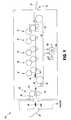
- FIG. 3shows an example of 6-up cutting.
- Controller 260receives a job specification 261 including two or more specified cut locations and causes transport mechanism 250 to laterally position two or more of the cutting devices 210 to cut the moving receiver 42 in the specified cut locations. This is discussed further below with reference to FIG. 4A .
- non-chad area 270is the printed page to be retained, and chad areas 275 a , 275 b are to be discarded.
- drive mechanism 230rotates the cutting wheels 212 .
- Cutting devices 210and specifically cutting wheels 212 , are mounted on shaft 232 , along which transport mechanism 250 selectively moves cutting wheels 212 .
- Drive mechanism 230drives shaft 232 to provide energy to rotate cutting wheels 212 .
- Pressure wheel 214is rotated by friction with the rotating cutting wheels 212 .
- a non-chad areais defined between each adjacent pair of cutting wheels 212 .
- drive mechanism 230rotates the pressure wheel 214 .
- Pressure wheel 214is mounted on shaft 234 , along which transport mechanism 250 selectively moves pressure wheel 214 .
- Drive mechanism 230drives shaft 234 to provide energy to rotate pressure wheel 214 .
- Cutting wheels 212are rotated by friction with the rotating pressure wheel 214 .
- both cutting wheels 212 and pressure wheel 214are mounted on driven shafts, and drive mechanism 230 drives both shafts.
- drive mechanism 230includes motor 231 for driving shaft 232 and motor 233 for driving shaft 234 .
- Motors 231 , 233are controlled by controller 260 , and can include encoders to report position back to controller 260 . Stepper or servomotors can be used.
- the driven shaft(s) 232 , 234extend beyond edge 292 of receiver 42 into area 251 .
- Transport mechanism 250is adapted to move at least one of the cutting devices 210 beyond the edge 292 of receiver 42 . This permits adjustment of the number of cuts: for n-up printing, the number of cutting devices 210 positioned over receiver 42 is n+1. All cutting devices 210 not required for n-up cutting are positioned off receiver 42 in area 251 .
- FIG. 3is an isometric view of a cutting apparatus according to an embodiment of the present invention.
- FIG. 3shows the apparatus configured for 6-up cutting, in which receiver 42 is slit into six strips. This is useful e.g. for business-card printing, in which each strip is one business card wide.
- Cutting wheels 212 , pressure wheel 214 , shaft 232 , shaft 234 , receiver 42 , feed direction 242 , transport mechanism 250 , area 251 , and edge 292are as shown in FIG. 2 .
- Each cutting device 210 a - 210 gcorresponds to cutting device 210 of FIG.
- all seven cutting devicesare positioned over receiver 42 .
- Cutting devices 210 a and 210 gare at the edges of receiver 42 , to trim those edges and permit full-bleed output.
- Cutting devices 210 b - 210 fare disposed over the internal area of receiver 42 , i.e. receiver 42 extends perpendicular to feed direction 242 on both sides of each cutting device 210 b - 210 f .
- Cutting devices 210 a - 210 gdefine respective chad areas 275 a - 275 g . Between the cutting devices are non-chad areas 270 a - 270 f , which can be chopped (cut perpendicular to feed direction 242 ) to form business cards.
- FIG. 4Ais a front view of a cutting device according to an embodiment of the present invention.
- Receiver 42is shown travelling in feed direction 242 , into the plane of the image.
- Cutting device 210 b , cutting wheels 212 , pressure wheel 214 , shaft 234 , and shaft 232are as shown in FIGS. 2 and 3 .
- Non-chad areas 270 a and 270 b on each side of cutting wheels 212are as shown in FIG. 3 .
- Chad area 275 bis as shown in FIG. 3 .
- All cutting devices 210 , 210 a - 210 gare the same, so this figure is representative of cutting devices besides cutting device 210 b.
- receiver 42passes through cutting device 210 b in feed direction 242 , it is divided into three pieces: non-chad area 270 a , chad area 275 b , and non-chad area 270 b.
- the surface of pressure wheel 214 of each cutting device 210is harder than the surface of the cutting wheels 212 . This provides a self-sharpening action, in which contact with pressure wheel 214 while cutting sharpens cutting wheels 212 . Hardness can be measured on a Shore A durometer or other hardness scales known in the art.
- pressure wheel 214 of each cutting device 210is harder than cutting wheels 212 .
- the bulk material of pressure wheel 214can be harder throughout than the bulk material of cutting wheels 212 . This also provides a self-sharpening action, in which contact with pressure wheel 214 while cutting sharpens cutting wheels 212 .
- friction member 410is disposed between the cutting wheels 212 of one of the cutting devices 210 b .
- Friction member 410is adapted to draw receiver 42 through cutting device 210 b .
- friction member 410 and pressure wheel 214 of cutting device 210 bcan form a nip 414 through which the moving receiver 42 is drawn.
- friction member 410is a compliant rotatable coaxial friction device such as a belt, roller, vacuum belt, or o-rings disposed between cutting blades 212 for positively driving receiver 42 through cutting device 210 .
- Transport mechanism 250includes rack 254 and pinion 252 .
- Pinion 252is driven by motor 253 to move cutting device 210 to a selected position with respect to receiver 42 .
- Controller 260( FIG. 2 ) provides power or drive commands to motor 253 .
- Motor 253can be a servomotor or stepper motor, and can include an encoder for position sensing and a transceiver for reporting position information to the controller.
- the terminals of the armature of motor 253can be shorted to provide braking action to hold cutting device 210 in place while it is not being moved.
- not all cutting deviceshave motors 253 .
- cutting devices 210 a and 210 chave motors 253 and cutting device 210 b does not.
- Cutting device 210 bis moved to the right by pushing it with cutting device 210 a and is moved to the left by pushing it with cutting device 210 c .
- cutting devices 210 a , 201 c , 210 e , and 210 gcan have motors 253
- cutting devices 210 b , 210 d , and 210 fcan lack motors 253 .
- Cutting devices without motorscan include friction elements or clutches to hold them in position when they are not being pushed.
- cutting devices 210 positioned at the edges of receiver 42can have only a single cutting wheel, or the outboard cutting wheels 212 of cutting devices 210 a , 210 g can be positioned off receiver 42 . If both cutting wheels 212 of cutting devices 210 , 210 g are positioned over receiver 42 , additional chad areas are cut outboard of chad areas 275 a , 275 g.
- FIG. 4Bis a side view of a cutting device according to an embodiment of the present invention.
- Cutting device 210 , cutting wheels 212 , receiver 42 , feed direction 242 , shafts 232 , 234 , pressure wheel 214 , rack 251 , pinion 252 , and motor 253are as shown in FIG. 4A .
- Cutting wheels 212turn with circumferential speed 4159 , which is the magnitude of linear velocity at the outer circumference of the wheel.
- circumferential speed 4159 of cutting wheels 212is at most 15% greater than the speed 442 (shown as the magnitude of the velocity vector of feed direction 242 ) of receiver 42 in feed direction 242 . This advantageously provides positive take-up of receiver 42 and maintains tension with reduced risk of tearing receiver 42 .
- circumferential speed 4159is less than, equal to, or greater than the speed of receiver 42 in feed direction 42 .
- At least one of the cutting devices 210includes deflector 460 .
- Deflector 460is laterally disposed in chad area 275 b ( FIG. 4A ) of cutting device 210 b and extends through the plane of receiver 42 .
- Deflector 460engages the chad as receiver 42 moves and directs the chad away from feed direction 242 of receiver 42 .
- Receiver 42can have folds, creases, and wrinkles, and still define a plane.
- the plane of receiver 42can be defined as the best-fit plane of all possible vectors from one point of receiver 42 to another in the area of receiver 42 between cutting wheels 212 and pressure wheel 214 .
- chad chopper 465is disposed to receive the chad 404 .
- Chad 404is a continuous strip of material cut out of receiver 42 .
- Chad chopper 465chops chad 404 into chad pieces 405 for easier handling and disposal.
- Chad chopper 465can be automatic scissors, a guillotine, an ulu, a laser, or another cutting device known in the art.
- Deflector 460 and chad chopper 465advantageously separate chad-handling structures from non-chad-handling structures, permitting simplified structures for both.
- transport mechanism 250can be employed. Some are described herein; others will be obvious to those skilled in the art. The embodiments below are not shown, but refer to parts on FIG. 2 .
- transport mechanism 250includes a guide rod having a helical groove, and at least one carriage corresponding to one of the cutting devices 210 .
- Each carriageincludes a support that rides on the guide rod, two side walls attached to the support and adapted to retain the corresponding cutting device in lateral position with respect to the support, a pin for selectively mechanically engaging the support to the helical groove, so that the support translates along the length of the guide rod when the guide rod rotates, and an actuator responsive to the controller for causing the pin to engage.
- transport mechanism 250includes a magnetic-levitation (maglev) track along which cutting devices 210 move.
- maglevmagnetic-levitation
- Examples of a maglev system useful with the present inventioninclude those described in U.S. Pat. No. 7,617,779, issued Nov. 17, 2009 to Studer, and U.S. Pat. No. 6,357,359, issued Mar. 19, 2002 to Davey et al., the disclosures of both of which are incorporated herein by reference.
- transport mechanism 250includes a cable, belt, or timing belt entrained around a drive pulley, and each cutting device 210 includes a grapple for selectively mechanically connecting the cutting device to the cable or belt.
- controller 260causes cutting device 210 to engage its grapple and thereby connect itself to the cable or belt.
- the controllerthen activates a drive motor to rotate the drive pulley, and move each point of the cable around a loop.
- the cutting device that is connected to the cable or beltwill move with the cable or belt. This is similar to the drive mechanism of a cable car or of an inkjet printer carriage.
- transport mechanism 250includes a ferromagnetic or other magnetic or ferrous cable or belt entrained around a drive pulley, and each cutting device 210 includes a magnetic grapple for selectively attracting the cable or belt.
- a grapple useful with the present inventionis described in U.S. Pat. No. 5,525,950, issued Jun. 11, 1996 to Wang, the disclosures of which are incorporated herein by reference.
- controller 260causes cutting device 210 to engage its grapple and thereby attach itself magnetically to the cable or belt.
- the controllerthen activates a drive motor to rotate the drive pulley, and move each point of the cable around a loop.
- the cutting device that is attached to the cable or beltwill move with the cable or belt.
- a telescoping pushrod with a keycan be used to selectively engage a cutting device 210 and push or pull it.
- a rack and pinioncan be employed, where the rack is an integral part of the rod supporting cutting devices 210 rather than a separate part.
Landscapes
- Life Sciences & Earth Sciences (AREA)
- Forests & Forestry (AREA)
- Engineering & Computer Science (AREA)
- Mechanical Engineering (AREA)
- Handling Of Sheets (AREA)
Abstract
Description
- 31,32,33,34,35 printing module
- 38 print image
- 39 fused image
- 40 supply unit
- 42,42A,42B receiver
- 50 transfer subsystem
- 60 fuser
- 62 fusing roller
- 64 pressure roller
- 66 fusing nip
- 68 release fluid application substation
- 69 output tray
- 70 finisher
- 81 transport web
- 86 cleaning station
- 99 logic and control unit (LCU)
- 100 printer
- 210,210a,210b,210c,210d,210e,210f,210gcutting device
- 212 cutting wheel
- 214 pressure wheel
- 230 drive mechanism
- 231 motor
- 232 shaft
- 233 motor
- 234 shaft
- 242 feed direction
- 250 transport mechanism
- 251 area
- 252 pinion
- 253 motor
- 254 rack
- 260 controller
- 261 job specification
- 270,270a,270b,270c,270d,270e,270fnon-chad area
- 275a,275b,275c,275d,275e,275f,275gchad area
- 292 edge of the receiver
- 404 chad
- 405 chad piece
- 410 friction member
- 414 nip
- 442 speed of the receiver
- 444 plane of the receiver
- 460 deflector
- 465 chad chopper
- 4159 circumferential speed
Claims (11)
Priority Applications (4)
| Application Number | Priority Date | Filing Date | Title |
|---|---|---|---|
| US12/781,878US8312798B2 (en) | 2010-05-18 | 2010-05-18 | Slitter with translating cutting devices |
| PCT/US2011/035734WO2011146272A1 (en) | 2010-05-18 | 2011-05-09 | Slitter with selectively movable cutting devices |
| CN201180024355.9ACN102905863B (en) | 2010-05-18 | 2011-05-09 | Slitter with selectively movable cutting device |
| EP20110720268EP2571662B1 (en) | 2010-05-18 | 2011-05-09 | Slitter with selectively movable cutting devices |
Applications Claiming Priority (1)
| Application Number | Priority Date | Filing Date | Title |
|---|---|---|---|
| US12/781,878US8312798B2 (en) | 2010-05-18 | 2010-05-18 | Slitter with translating cutting devices |
Publications (2)
| Publication Number | Publication Date |
|---|---|
| US20110283855A1 US20110283855A1 (en) | 2011-11-24 |
| US8312798B2true US8312798B2 (en) | 2012-11-20 |
Family
ID=44275715
Family Applications (1)
| Application Number | Title | Priority Date | Filing Date |
|---|---|---|---|
| US12/781,878Expired - Fee RelatedUS8312798B2 (en) | 2010-05-18 | 2010-05-18 | Slitter with translating cutting devices |
Country Status (4)
| Country | Link |
|---|---|
| US (1) | US8312798B2 (en) |
| EP (1) | EP2571662B1 (en) |
| CN (1) | CN102905863B (en) |
| WO (1) | WO2011146272A1 (en) |
Cited By (10)
| Publication number | Priority date | Publication date | Assignee | Title |
|---|---|---|---|---|
| US20130152750A1 (en)* | 2007-08-10 | 2013-06-20 | Arthur George Chilcott | Knife holder |
| US20140121085A1 (en)* | 2012-10-31 | 2014-05-01 | Brian J. Kwarta | Receiver-puncturing device with translating puncturing devices |
| US20150343660A1 (en)* | 2014-05-30 | 2015-12-03 | Catbridge Machinery Llc | Score Knife Positioner |
| US20160114426A1 (en)* | 2014-10-22 | 2016-04-28 | Xerox Corporation | Parallel belt system for cut sheet transport in a laser cutter |
| US20190039143A1 (en)* | 2016-01-12 | 2019-02-07 | Dalian Field Heavy-Machnery Manufacturing Co., Ltd | Novel method for synchronous and fixed-length cutting-off of continuously-processed materials through multiple cutter holders arranged in series |
| US11020929B2 (en)* | 2017-02-24 | 2021-06-01 | Mitsubishi Heavy Industries Machinery Systems, Ltd. | Corrugated board web cutting device and corrugated board manufacturing device |
| US20220055241A1 (en)* | 2020-08-21 | 2022-02-24 | Michael Hörauf Maschinenfabrik Gmbh Und Co. Kg | Circular knife device |
| US11285740B2 (en) | 2018-04-30 | 2022-03-29 | Hewlett-Packard Development Company, L.P. | Cutter module positioning for full-bleed printing |
| WO2022076453A1 (en) | 2020-10-05 | 2022-04-14 | Kodak Alaris Inc. | Printer waste diverters |
| US20240198552A1 (en)* | 2021-04-19 | 2024-06-20 | Kyocera Corporation | Unit for cutting apparatus and cutting apparatus |
Families Citing this family (51)
| Publication number | Priority date | Publication date | Assignee | Title |
|---|---|---|---|---|
| EP2776221B1 (en) | 2011-11-10 | 2016-07-13 | Packsize LLC | Converting machine |
| US8869668B1 (en)* | 2011-11-18 | 2014-10-28 | Hormel Foods Corporation | Product cutter |
| CN102581861B (en)* | 2011-12-23 | 2015-12-16 | 高树满 | A kind of cutter for food cutting machine |
| JP5959858B2 (en)* | 2012-01-13 | 2016-08-02 | 株式会社内田洋行 | Automatic card cutter |
| EP2620401B1 (en) | 2012-01-27 | 2016-01-27 | UCHIDA YOKO Co., Ltd. | Automatic card-cutting apparatus |
| CN103286808B (en)* | 2012-02-28 | 2017-03-01 | 株式会社内田洋行 | Automatic card cutter sweep |
| ITMI20120704A1 (en)* | 2012-04-27 | 2013-10-28 | Fotoba Int Srl | CUTTER |
| CN102729286B (en)* | 2012-06-11 | 2015-05-20 | 杭州大华工控技术有限公司 | Automatic slitter positioning system of high-speed intelligent dividing and cutting machine |
| US20140116218A1 (en)* | 2012-10-31 | 2014-05-01 | Brian J. Kwarta | Perforator with backer and translating perforating devices |
| CN103846959A (en)* | 2012-12-04 | 2014-06-11 | 包格格 | Equidistance regulator |
| CN103332522B (en)* | 2013-05-16 | 2016-09-28 | 何春明 | The longitudinal cutting device of paper cutter and control method thereof |
| EP2815859B1 (en)* | 2013-06-19 | 2016-04-27 | Valmet Technologies, Inc. | Slitter positioning arrangement of a slitter-winder of a fiber web production line |
| JP6320062B2 (en)* | 2014-02-03 | 2018-05-09 | 三菱電機株式会社 | Thermal transfer printer |
| CN104029235B (en)* | 2014-05-27 | 2016-03-09 | 常州市武进区半导体照明应用技术研究院 | For cutting cutting mechanism and the method for flexible base board LED light source device |
| CN104149388A (en)* | 2014-08-15 | 2014-11-19 | 江苏申凯包装高新技术股份有限公司 | Cutter combined holder |
| US10093438B2 (en) | 2014-12-29 | 2018-10-09 | Packsize Llc | Converting machine |
| CN104816326B (en)* | 2015-05-04 | 2016-08-24 | 广东万联包装机械有限公司 | A kind of slitter |
| CN104960245B (en)* | 2015-07-22 | 2017-08-01 | 青岛澳邦量器有限责任公司 | A kind of cardboard line ball cutting combination knife |
| JP2019511370A (en)* | 2016-04-07 | 2019-04-25 | ヒューレット−パッカード デベロップメント カンパニー エル.ピー.Hewlett‐Packard Development Company, L.P. | Cutting module |
| US10792829B2 (en) | 2016-04-26 | 2020-10-06 | Hewlett-Packard Development Company, L.P. | Cutting modules |
| US10850469B2 (en) | 2016-06-16 | 2020-12-01 | Packsize Llc | Box forming machine |
| WO2017218296A1 (en) | 2016-06-16 | 2017-12-21 | Packsize Llc | A box template production system and method |
| JP6927574B2 (en)* | 2016-09-21 | 2021-09-01 | デュプロ精工株式会社 | Slitters, sheet cutting machines, and sheet processing equipment |
| US11242214B2 (en) | 2017-01-18 | 2022-02-08 | Packsize Llc | Converting machine with fold sensing mechanism |
| CN106863434B (en)* | 2017-02-23 | 2018-10-16 | 京东方科技集团股份有限公司 | Remove device and its operating method, cutter device |
| SE1750727A1 (en) | 2017-06-08 | 2018-10-09 | Packsize Llc | Tool head positioning mechanism for a converting machine, and method for positioning a plurality of tool heads in a converting machine |
| CN107176784B (en)* | 2017-07-13 | 2023-07-18 | 嘉兴沃尔德金刚石工具有限公司 | A holeless cutter wheel |
| CN108248118B (en)* | 2017-11-28 | 2019-06-07 | 江阴宝柏包装有限公司 | A kind of equipment that formation easily tears mark |
| US11192392B2 (en) | 2018-01-30 | 2021-12-07 | Hewlett-Packard Development Company, L.P. | Media cutting device and method with contact-free coupling of upper and lower members |
| US20200353635A1 (en)* | 2018-01-30 | 2020-11-12 | Hewlett-Packard Development Company, L.P. | Media cutting arrangement and method |
| CN108312620A (en)* | 2018-01-31 | 2018-07-24 | 六安维奥智能科技有限公司 | A kind of paper cup bottom paper guillotine |
| CN108582178A (en)* | 2018-03-31 | 2018-09-28 | 利辛县宏天建材有限责任公司 | A kind of macromolecule web material cut-out equipment |
| CN108527501A (en)* | 2018-03-31 | 2018-09-14 | 利辛县宏天建材有限责任公司 | A kind of macromolecule web material trimming equipment |
| CN108748373A (en)* | 2018-03-31 | 2018-11-06 | 利辛县宏天建材有限责任公司 | A kind of macromolecule web material edge-neatening apparatus and its operation method |
| US11247427B2 (en) | 2018-04-05 | 2022-02-15 | Avercon BVBA | Packaging machine infeed, separation, and creasing mechanisms |
| US11305903B2 (en) | 2018-04-05 | 2022-04-19 | Avercon BVBA | Box template folding process and mechanisms |
| US20210331496A1 (en)* | 2018-04-25 | 2021-10-28 | Hewlett-Packard Development Company, L.P. | Cutter module and method |
| US11565539B2 (en) | 2018-04-30 | 2023-01-31 | Hewlett-Packard Development Company, L.P. | Forward and backward rotation of printer cutters |
| DE112019003075T5 (en) | 2018-06-21 | 2021-03-25 | Packsize Llc | PACKAGING DEVICE AND SYSTEMS |
| JP7317543B2 (en)* | 2019-03-29 | 2023-07-31 | キヤノン株式会社 | Recording device and transport device |
| CN110370337A (en)* | 2019-07-30 | 2019-10-25 | 南通盟鼎新材料有限公司 | A kind of efficient gantry slicer |
| CN111996785B (en)* | 2020-08-20 | 2022-06-24 | 青岛龙蕾五金有限公司 | Cloth cutting device |
| KR102249224B1 (en)* | 2020-10-16 | 2021-05-06 | 이석현 | Cutting apparatus strip for diagnostic kit |
| CN112454472A (en)* | 2020-11-04 | 2021-03-09 | 湖南省九喜日化有限公司 | Cutting device is used in playing card production |
| JP7633797B2 (en)* | 2020-11-20 | 2025-02-20 | キヤノン株式会社 | SHEET CUTTING DEVICE AND IMAGE FORMING SYSTEM |
| CN112643791A (en)* | 2020-12-16 | 2021-04-13 | 苏州工业园区久泰精密电子有限公司 | Machining device and machining method of ultra-large layout movable die-cutting circular knife machine |
| WO2023044062A1 (en)* | 2021-09-17 | 2023-03-23 | Encore Packaging Llc | Device for producing slit sheet packing material |
| IT202200006800A1 (en)* | 2022-04-06 | 2023-10-06 | Tecnau Srl | CUTTER AND SEPARATION METHOD FOR SHEETS PRINTED FROM CONTINUOUS TAPE SUITABLE FOR SEVERAL LONGITUDINAL SUBDIVISIONS AND RELATIVE TAPE |
| US12172791B2 (en)* | 2022-09-15 | 2024-12-24 | Amazon Technologies, Inc. | Systems and methods for longitudinal scoring of roll-formed containers |
| IT202200020526A1 (en)* | 2022-10-06 | 2024-04-06 | Sormec S R L | CUTTING UNIT AND PACKAGING MAKING MACHINE INCLUDING SAID CUTTING UNIT |
| CN117207595A (en)* | 2023-10-27 | 2023-12-12 | 广东力顺源智能自动化有限公司 | Automatic magnet mounting mechanism for box body |
Citations (27)
| Publication number | Priority date | Publication date | Assignee | Title |
|---|---|---|---|---|
| US299982A (en)* | 1884-06-10 | hodgson | ||
| US3422714A (en)* | 1966-12-23 | 1969-01-21 | S & S Enterprises Inc | Quick-set shear slitter |
| US4215609A (en)* | 1979-02-09 | 1980-08-05 | Molins Machine Company, Inc. | Slitter scorer having upper and lower pairs of shafts selectively rotated by a single drive |
| US4445409A (en)* | 1981-01-22 | 1984-05-01 | Karl Mohr | Device for cutting paper, cardboard, and similar materials |
| US4604934A (en)* | 1985-05-08 | 1986-08-12 | Ppg Industries, Inc. | Carriage train precision linear positioning system |
| US4649782A (en)* | 1983-11-08 | 1987-03-17 | Elio Cavagna | Cutting units for cutting material in bands into strips |
| US5378221A (en)* | 1992-10-23 | 1995-01-03 | Corrugated Gear & Sprocket, Inc. | Assembly and method for axially aligning slotting, trimming, scoring or like heads |
| US5797830A (en)* | 1996-03-12 | 1998-08-25 | Albert Flores | Multi use paper and card stock cutter |
| US5907984A (en)* | 1995-04-19 | 1999-06-01 | Cutting Edge Inc. | Parallel cutting assembly for cutting sheet material |
| US6469806B1 (en)* | 1998-12-18 | 2002-10-22 | Xerox Corporation | Method and apparatus for reducing excess developer material at the edges of print sheets of full bleed images via digital image processing |
| US20030066400A1 (en)* | 2001-10-10 | 2003-04-10 | Bwg Bergwerk- Und Walzwerk-Maschinenbau Gmbh | Method and apparatus for the trimming of strip, especially hot roll metal strip |
| US6627334B2 (en)* | 2000-01-24 | 2003-09-30 | Fuji Photo Film Co., Ltd. | Magnetic tape and method and apparatus for slitting magnetic tape webs |
| US20030192413A1 (en)* | 1996-03-08 | 2003-10-16 | Fuji Photo Film Co., Ltd. | Method of switching cutting knife arrangements |
| US20030209115A1 (en)* | 2002-05-07 | 2003-11-13 | Burkart Arthur P. | Apparatus and method for positioning tool heads in spaced linear array |
| US20040016334A1 (en)* | 2002-07-24 | 2004-01-29 | Bruno Lindenblatt | Log merchandiser |
| US20040118260A1 (en)* | 2002-11-06 | 2004-06-24 | Shui-Yi Lee | Sheet cutter for making business cards |
| US20050079968A1 (en) | 2003-10-09 | 2005-04-14 | Trovinger Steven W. | Sheet folding and trimming apparatus |
| US20050217447A1 (en)* | 2004-03-31 | 2005-10-06 | R. J. Reynolds Tobacco Company | Slitter device with adjustable blade |
| US7028598B2 (en)* | 2002-03-22 | 2006-04-18 | Kabushiki Kaisha Tokyo Kikai Seisakusho | Apparatus for longitudinally perforating a web of paper in a rotary printing press |
| US7134372B2 (en)* | 2001-11-08 | 2006-11-14 | Blue Ip, Inc. | CNC slitter machine |
| US7137625B2 (en)* | 2002-02-12 | 2006-11-21 | Ricoh Company, Ltd. | Sheet finisher including means for setting cutting position image forming system including the sheet finisher |
| US20070000362A1 (en)* | 2005-06-29 | 2007-01-04 | Chuan-Sheng Lin | Method for positioning rotary knife of cutter and apparatus therefor |
| US20090071305A1 (en)* | 2007-09-14 | 2009-03-19 | L&P Property Management Company | Programmable border slitter |
| US20090084241A1 (en)* | 2007-09-28 | 2009-04-02 | Fujifilm Corporation | Planographic printing plate manufacturing apparatus |
| US20100218658A1 (en)* | 2007-09-14 | 2010-09-02 | L&P Property Management Company | Programmable border slitter |
| US7861754B2 (en)* | 2007-06-19 | 2011-01-04 | Usnr/Kockums Cancar Company | Edger with staggered saws |
| US8221873B2 (en)* | 2008-09-30 | 2012-07-17 | Fujifilm Corporation | Film slitter, film and film slitting method |
Family Cites Families (21)
| Publication number | Priority date | Publication date | Assignee | Title |
|---|---|---|---|---|
| US1900183A (en)* | 1932-04-14 | 1933-03-07 | Cameron Machine Co | Slitting device |
| JPS5336636B2 (en)* | 1974-04-24 | 1978-10-04 | ||
| US4398678A (en)* | 1981-04-29 | 1983-08-16 | Eastman Kodak Company | Variable-width web slitting and winding apparatus |
| US4561335A (en)* | 1983-09-21 | 1985-12-31 | Dienes Werke fur Maschinenteille, GmbH & Co. KG | Slitting mechanism having a removable blade |
| JP2555892B2 (en) | 1989-10-03 | 1996-11-20 | 日本鋼管株式会社 | Method and apparatus for identifying life of noble metal electrode for electroplating |
| JPH08157Y2 (en)* | 1990-03-26 | 1996-01-10 | 東レ株式会社 | Sheet-like slitter |
| US6357359B1 (en) | 1990-10-23 | 2002-03-19 | Kent R. Davey | Integrated high speed maglev system utilizing an active lift |
| JP2719093B2 (en)* | 1992-09-29 | 1998-02-25 | ゼロックス コーポレイション | Perforation and / or slitting device |
| JPH08290392A (en) | 1995-04-20 | 1996-11-05 | Hagi Seimitsu Denshi Kk | Shearing machine used for preparing name card of simple type, and shearing method using it |
| US5525950A (en) | 1995-08-11 | 1996-06-11 | Wang; Chin-Yuan | Magnetic base |
| JPH09248794A (en) | 1996-03-13 | 1997-09-22 | Isowa Corp | Slitter device with blade polishing function |
| US5775193A (en)* | 1996-06-25 | 1998-07-07 | Pratt; Donald P. | Crush-slitting structure |
| JP2002086388A (en) | 2000-09-08 | 2002-03-26 | Ichikin Kogyosha:Kk | Cutter apparatus for sheet material |
| US6608641B1 (en) | 2002-06-27 | 2003-08-19 | Nexpress Solutions Llc | Electrophotographic apparatus and method for using textured receivers |
| DE20304105U1 (en)* | 2003-03-12 | 2003-05-15 | Batshoun, Samir, 85399 Hallbergmoos | Device for simultaneous joining and punching of two layers, comprising additional cutting device |
| AU2005214234B2 (en) | 2004-02-24 | 2010-05-27 | Duplo Seiko Corporation | Paper sheet processing device |
| JP2005239307A (en)* | 2004-02-24 | 2005-09-08 | Duplo Seiko Corp | Paper processing device |
| US7617779B2 (en) | 2004-11-15 | 2009-11-17 | Sandor Shapery | Linear brushless D.C. motor with stationary armature and field and with integratable magnetic suspension |
| US7502582B2 (en) | 2004-12-22 | 2009-03-10 | Eastman Kodak Company | Method and apparatus for printing using a tandem electrostatographic printer |
| JP4885615B2 (en) | 2006-05-31 | 2012-02-29 | デュプロ精工株式会社 | Paper processing equipment |
| CN101073889B (en)* | 2006-08-31 | 2011-05-18 | 杭州中凌广告器材有限公司 | Cutter and cutting method |
- 2010
- 2010-05-18USUS12/781,878patent/US8312798B2/ennot_activeExpired - Fee Related
- 2011
- 2011-05-09EPEP20110720268patent/EP2571662B1/ennot_activeNot-in-force
- 2011-05-09WOPCT/US2011/035734patent/WO2011146272A1/enactiveApplication Filing
- 2011-05-09CNCN201180024355.9Apatent/CN102905863B/ennot_activeExpired - Fee Related
Patent Citations (27)
| Publication number | Priority date | Publication date | Assignee | Title |
|---|---|---|---|---|
| US299982A (en)* | 1884-06-10 | hodgson | ||
| US3422714A (en)* | 1966-12-23 | 1969-01-21 | S & S Enterprises Inc | Quick-set shear slitter |
| US4215609A (en)* | 1979-02-09 | 1980-08-05 | Molins Machine Company, Inc. | Slitter scorer having upper and lower pairs of shafts selectively rotated by a single drive |
| US4445409A (en)* | 1981-01-22 | 1984-05-01 | Karl Mohr | Device for cutting paper, cardboard, and similar materials |
| US4649782A (en)* | 1983-11-08 | 1987-03-17 | Elio Cavagna | Cutting units for cutting material in bands into strips |
| US4604934A (en)* | 1985-05-08 | 1986-08-12 | Ppg Industries, Inc. | Carriage train precision linear positioning system |
| US5378221A (en)* | 1992-10-23 | 1995-01-03 | Corrugated Gear & Sprocket, Inc. | Assembly and method for axially aligning slotting, trimming, scoring or like heads |
| US5907984A (en)* | 1995-04-19 | 1999-06-01 | Cutting Edge Inc. | Parallel cutting assembly for cutting sheet material |
| US20030192413A1 (en)* | 1996-03-08 | 2003-10-16 | Fuji Photo Film Co., Ltd. | Method of switching cutting knife arrangements |
| US5797830A (en)* | 1996-03-12 | 1998-08-25 | Albert Flores | Multi use paper and card stock cutter |
| US6469806B1 (en)* | 1998-12-18 | 2002-10-22 | Xerox Corporation | Method and apparatus for reducing excess developer material at the edges of print sheets of full bleed images via digital image processing |
| US6627334B2 (en)* | 2000-01-24 | 2003-09-30 | Fuji Photo Film Co., Ltd. | Magnetic tape and method and apparatus for slitting magnetic tape webs |
| US20030066400A1 (en)* | 2001-10-10 | 2003-04-10 | Bwg Bergwerk- Und Walzwerk-Maschinenbau Gmbh | Method and apparatus for the trimming of strip, especially hot roll metal strip |
| US7134372B2 (en)* | 2001-11-08 | 2006-11-14 | Blue Ip, Inc. | CNC slitter machine |
| US7137625B2 (en)* | 2002-02-12 | 2006-11-21 | Ricoh Company, Ltd. | Sheet finisher including means for setting cutting position image forming system including the sheet finisher |
| US7028598B2 (en)* | 2002-03-22 | 2006-04-18 | Kabushiki Kaisha Tokyo Kikai Seisakusho | Apparatus for longitudinally perforating a web of paper in a rotary printing press |
| US20030209115A1 (en)* | 2002-05-07 | 2003-11-13 | Burkart Arthur P. | Apparatus and method for positioning tool heads in spaced linear array |
| US20040016334A1 (en)* | 2002-07-24 | 2004-01-29 | Bruno Lindenblatt | Log merchandiser |
| US20040118260A1 (en)* | 2002-11-06 | 2004-06-24 | Shui-Yi Lee | Sheet cutter for making business cards |
| US20050079968A1 (en) | 2003-10-09 | 2005-04-14 | Trovinger Steven W. | Sheet folding and trimming apparatus |
| US20050217447A1 (en)* | 2004-03-31 | 2005-10-06 | R. J. Reynolds Tobacco Company | Slitter device with adjustable blade |
| US20070000362A1 (en)* | 2005-06-29 | 2007-01-04 | Chuan-Sheng Lin | Method for positioning rotary knife of cutter and apparatus therefor |
| US7861754B2 (en)* | 2007-06-19 | 2011-01-04 | Usnr/Kockums Cancar Company | Edger with staggered saws |
| US20090071305A1 (en)* | 2007-09-14 | 2009-03-19 | L&P Property Management Company | Programmable border slitter |
| US20100218658A1 (en)* | 2007-09-14 | 2010-09-02 | L&P Property Management Company | Programmable border slitter |
| US20090084241A1 (en)* | 2007-09-28 | 2009-04-02 | Fujifilm Corporation | Planographic printing plate manufacturing apparatus |
| US8221873B2 (en)* | 2008-09-30 | 2012-07-17 | Fujifilm Corporation | Film slitter, film and film slitting method |
Non-Patent Citations (5)
| Title |
|---|
| CRICUT Personal Electronic Cutter, Provo Craft on line user manual at website http://www.cricut.com/res/mManual/CricutUserManual.pdf. |
| MBMCorp, BC-10 Business Card Cutter Operation Manual, Web site http://www.mbmcorp.com/pdfs/br-0818.pdf. |
| MBMCorp, BC-10 Business Card Cutter Operation Manual, Web site http://www.mbmcorp.com/pdfs/br—0818.pdf. |
| PL265 Fully Automatic Programmable Cutter, Martin Yale Industries at website http://www.martinyale.com/product-details.aspx?SKU=Intimus%20PL215%20&ReturnURL=%2fproduct-listing.aspx%3fCategory%3d1579e4d1-c382-461a-9de0-453e7a74e279%26page%3d1%26pagesize%3d10%26text%3d%26EPCString1%3d%26EPCString2%3d%26EPCString3%3d. |
| PL265 Fully Automatic Programmable Cutter, Martin Yale Industries at website http://www.martinyale.com/product—details.aspx?SKU=Intimus%20PL215%20&ReturnURL=%2fproduct—listing.aspx%3fCategory%3d1579e4d1-c382-461a-9de0-453e7a74e279%26page%3d1%26pagesize%3d10%26text%3d%26EPCString1%3d%26EPCString2%3d%26EPCString3%3d. |
Cited By (16)
| Publication number | Priority date | Publication date | Assignee | Title |
|---|---|---|---|---|
| US20130152750A1 (en)* | 2007-08-10 | 2013-06-20 | Arthur George Chilcott | Knife holder |
| US20140121085A1 (en)* | 2012-10-31 | 2014-05-01 | Brian J. Kwarta | Receiver-puncturing device with translating puncturing devices |
| US10406709B2 (en)* | 2014-05-30 | 2019-09-10 | Catbridge Machinery, Llc | Score knife positioner |
| US20150343660A1 (en)* | 2014-05-30 | 2015-12-03 | Catbridge Machinery Llc | Score Knife Positioner |
| US20150343658A1 (en)* | 2014-05-30 | 2015-12-03 | Catbridge Machinery Llc | Score Knife Positioner |
| US10124505B2 (en) | 2014-05-30 | 2018-11-13 | Catbridge Machinery Llc | Score knife positioner |
| US10124504B2 (en)* | 2014-05-30 | 2018-11-13 | Catbridge Machinery Llc | Score knife positioner |
| US20160114426A1 (en)* | 2014-10-22 | 2016-04-28 | Xerox Corporation | Parallel belt system for cut sheet transport in a laser cutter |
| US9492891B2 (en)* | 2014-10-22 | 2016-11-15 | Xerox Corporation | Parallel belt system for cut sheet transport in a laser cutter |
| US20190039143A1 (en)* | 2016-01-12 | 2019-02-07 | Dalian Field Heavy-Machnery Manufacturing Co., Ltd | Novel method for synchronous and fixed-length cutting-off of continuously-processed materials through multiple cutter holders arranged in series |
| US11020929B2 (en)* | 2017-02-24 | 2021-06-01 | Mitsubishi Heavy Industries Machinery Systems, Ltd. | Corrugated board web cutting device and corrugated board manufacturing device |
| US11285740B2 (en) | 2018-04-30 | 2022-03-29 | Hewlett-Packard Development Company, L.P. | Cutter module positioning for full-bleed printing |
| US20220055241A1 (en)* | 2020-08-21 | 2022-02-24 | Michael Hörauf Maschinenfabrik Gmbh Und Co. Kg | Circular knife device |
| WO2022076453A1 (en) | 2020-10-05 | 2022-04-14 | Kodak Alaris Inc. | Printer waste diverters |
| US11839992B2 (en) | 2020-10-05 | 2023-12-12 | Kodak Alaris Inc. | Printer waste diverters |
| US20240198552A1 (en)* | 2021-04-19 | 2024-06-20 | Kyocera Corporation | Unit for cutting apparatus and cutting apparatus |
Also Published As
| Publication number | Publication date |
|---|---|
| EP2571662B1 (en) | 2015-03-04 |
| US20110283855A1 (en) | 2011-11-24 |
| WO2011146272A1 (en) | 2011-11-24 |
| CN102905863B (en) | 2015-06-10 |
| CN102905863A (en) | 2013-01-30 |
| EP2571662A1 (en) | 2013-03-27 |
Similar Documents
| Publication | Publication Date | Title |
|---|---|---|
| US8312798B2 (en) | Slitter with translating cutting devices | |
| US20140121085A1 (en) | Receiver-puncturing device with translating puncturing devices | |
| US8316749B2 (en) | Finisher for cutting or scoring receiver | |
| US20140116218A1 (en) | Perforator with backer and translating perforating devices | |
| US20140116215A1 (en) | Perforator with translating perforating devices | |
| EP2576199B1 (en) | Stacking booklet sheets on adjustable-angle ramp | |
| US20110293351A1 (en) | Print cutting system | |
| US8437687B2 (en) | Calculating booklet sheet length using toner thickness | |
| EP2569167B1 (en) | Making booklet by iteratively folding and cutting | |
| US20110293349A1 (en) | Printer with variable length receiver supply | |
| US20110269613A1 (en) | Producing booklet by cutting before printing | |
| US8503902B2 (en) | Electrophotographic printer with charging-roller cleaner | |
| US8406672B2 (en) | Bending receiver using heat-shrinkable toner | |
| US8565654B2 (en) | Electrophotographic printer transfer station with ski | |
| US8227165B2 (en) | Bending receiver using heat-shrinkable film | |
| US20150277259A1 (en) | Method for determining electro-photographic process control set points | |
| US20110292437A1 (en) | Method for printing a set of images | |
| US20120189364A1 (en) | Reducing drag on rotatable web drive member |
Legal Events
| Date | Code | Title | Description |
|---|---|---|---|
| AS | Assignment | Owner name:EASTMAN KODAK COMPANY, NEW YORK Free format text:ASSIGNMENT OF ASSIGNORS INTEREST;ASSIGNORS:KWARTA, BRIAN J.;SHIFLEY, JAMES D.;SIGNING DATES FROM 20100527 TO 20100607;REEL/FRAME:024952/0328 | |
| AS | Assignment | Owner name:CITICORP NORTH AMERICA, INC., AS AGENT, NEW YORK Free format text:SECURITY INTEREST;ASSIGNORS:EASTMAN KODAK COMPANY;PAKON, INC.;REEL/FRAME:028201/0420 Effective date:20120215 | |
| STCF | Information on status: patent grant | Free format text:PATENTED CASE | |
| AS | Assignment | Owner name:WILMINGTON TRUST, NATIONAL ASSOCIATION, AS AGENT, Free format text:PATENT SECURITY AGREEMENT;ASSIGNORS:EASTMAN KODAK COMPANY;PAKON, INC.;REEL/FRAME:030122/0235 Effective date:20130322 Owner name:WILMINGTON TRUST, NATIONAL ASSOCIATION, AS AGENT, MINNESOTA Free format text:PATENT SECURITY AGREEMENT;ASSIGNORS:EASTMAN KODAK COMPANY;PAKON, INC.;REEL/FRAME:030122/0235 Effective date:20130322 | |
| RR | Request for reexamination filed | Effective date:20130515 | |
| AS | Assignment | Owner name:BARCLAYS BANK PLC, AS ADMINISTRATIVE AGENT, NEW YORK Free format text:INTELLECTUAL PROPERTY SECURITY AGREEMENT (SECOND LIEN);ASSIGNORS:EASTMAN KODAK COMPANY;FAR EAST DEVELOPMENT LTD.;FPC INC.;AND OTHERS;REEL/FRAME:031159/0001 Effective date:20130903 Owner name:JPMORGAN CHASE BANK, N.A., AS ADMINISTRATIVE, DELAWARE Free format text:INTELLECTUAL PROPERTY SECURITY AGREEMENT (FIRST LIEN);ASSIGNORS:EASTMAN KODAK COMPANY;FAR EAST DEVELOPMENT LTD.;FPC INC.;AND OTHERS;REEL/FRAME:031158/0001 Effective date:20130903 Owner name:PAKON, INC., NEW YORK Free format text:RELEASE OF SECURITY INTEREST IN PATENTS;ASSIGNORS:CITICORP NORTH AMERICA, INC., AS SENIOR DIP AGENT;WILMINGTON TRUST, NATIONAL ASSOCIATION, AS JUNIOR DIP AGENT;REEL/FRAME:031157/0451 Effective date:20130903 Owner name:JPMORGAN CHASE BANK, N.A., AS ADMINISTRATIVE, DELA Free format text:INTELLECTUAL PROPERTY SECURITY AGREEMENT (FIRST LIEN);ASSIGNORS:EASTMAN KODAK COMPANY;FAR EAST DEVELOPMENT LTD.;FPC INC.;AND OTHERS;REEL/FRAME:031158/0001 Effective date:20130903 Owner name:EASTMAN KODAK COMPANY, NEW YORK Free format text:RELEASE OF SECURITY INTEREST IN PATENTS;ASSIGNORS:CITICORP NORTH AMERICA, INC., AS SENIOR DIP AGENT;WILMINGTON TRUST, NATIONAL ASSOCIATION, AS JUNIOR DIP AGENT;REEL/FRAME:031157/0451 Effective date:20130903 Owner name:BARCLAYS BANK PLC, AS ADMINISTRATIVE AGENT, NEW YO Free format text:INTELLECTUAL PROPERTY SECURITY AGREEMENT (SECOND LIEN);ASSIGNORS:EASTMAN KODAK COMPANY;FAR EAST DEVELOPMENT LTD.;FPC INC.;AND OTHERS;REEL/FRAME:031159/0001 Effective date:20130903 Owner name:BANK OF AMERICA N.A., AS AGENT, MASSACHUSETTS Free format text:INTELLECTUAL PROPERTY SECURITY AGREEMENT (ABL);ASSIGNORS:EASTMAN KODAK COMPANY;FAR EAST DEVELOPMENT LTD.;FPC INC.;AND OTHERS;REEL/FRAME:031162/0117 Effective date:20130903 | |
| CC | Certificate of correction | ||
| B1 | Reexamination certificate first reexamination | Free format text:CLAIMS 1-7, 10 AND 11 ARE CANCELLED. CLAIMS 8 AND 9 WERE NOT REEXAMINED. | |
| FPAY | Fee payment | Year of fee payment:4 | |
| AS | Assignment | Owner name:MIDWEST ATHLETICS AND SPORTS ALLIANCE LLC, NEBRASK Free format text:ASSIGNMENT OF ASSIGNORS INTEREST;ASSIGNOR:EASTMAN KODAK COMPANY;REEL/FRAME:044811/0502 Effective date:20171120 | |
| AS | Assignment | Owner name:MIDWEST ATHLETICS AND SPORTS ALLIANCE LLC, NEBRASK Free format text:ASSIGNMENT OF ASSIGNORS INTEREST;ASSIGNOR:EASTMAN KODAK COMPANY;REEL/FRAME:044811/0245 Effective date:20171120 | |
| AS | Assignment | Owner name:EASTMAN KODAK COMPANY, NEW YORK Free format text:RELEASE BY SECURED PARTY;ASSIGNOR:BANK OF AMERICA N.A.;REEL/FRAME:045095/0299 Effective date:20171115 Owner name:EASTMAN KODAK COMPANY, NEW YORK Free format text:RELEASE BY SECURED PARTY;ASSIGNOR:JP MORGAN CHASE BANK N.A.;REEL/FRAME:045095/0317 Effective date:20171115 | |
| AS | Assignment | Owner name:FPC, INC., NEW YORK Free format text:RELEASE BY SECURED PARTY;ASSIGNOR:JP MORGAN CHASE BANK, N.A., AS ADMINISTRATIVE AGENT;REEL/FRAME:050239/0001 Effective date:20190617 Owner name:KODAK REALTY, INC., NEW YORK Free format text:RELEASE BY SECURED PARTY;ASSIGNOR:JP MORGAN CHASE BANK, N.A., AS ADMINISTRATIVE AGENT;REEL/FRAME:050239/0001 Effective date:20190617 Owner name:KODAK IMAGING NETWORK, INC., NEW YORK Free format text:RELEASE BY SECURED PARTY;ASSIGNOR:JP MORGAN CHASE BANK, N.A., AS ADMINISTRATIVE AGENT;REEL/FRAME:050239/0001 Effective date:20190617 Owner name:EASTMAN KODAK COMPANY, NEW YORK Free format text:RELEASE BY SECURED PARTY;ASSIGNOR:JP MORGAN CHASE BANK, N.A., AS ADMINISTRATIVE AGENT;REEL/FRAME:050239/0001 Effective date:20190617 Owner name:LASER PACIFIC MEDIA CORPORATION, NEW YORK Free format text:RELEASE BY SECURED PARTY;ASSIGNOR:JP MORGAN CHASE BANK, N.A., AS ADMINISTRATIVE AGENT;REEL/FRAME:050239/0001 Effective date:20190617 Owner name:KODAK (NEAR EAST), INC., NEW YORK Free format text:RELEASE BY SECURED PARTY;ASSIGNOR:JP MORGAN CHASE BANK, N.A., AS ADMINISTRATIVE AGENT;REEL/FRAME:050239/0001 Effective date:20190617 Owner name:KODAK AVIATION LEASING LLC, NEW YORK Free format text:RELEASE BY SECURED PARTY;ASSIGNOR:JP MORGAN CHASE BANK, N.A., AS ADMINISTRATIVE AGENT;REEL/FRAME:050239/0001 Effective date:20190617 Owner name:QUALEX, INC., NEW YORK Free format text:RELEASE BY SECURED PARTY;ASSIGNOR:JP MORGAN CHASE BANK, N.A., AS ADMINISTRATIVE AGENT;REEL/FRAME:050239/0001 Effective date:20190617 Owner name:NPEC, INC., NEW YORK Free format text:RELEASE BY SECURED PARTY;ASSIGNOR:JP MORGAN CHASE BANK, N.A., AS ADMINISTRATIVE AGENT;REEL/FRAME:050239/0001 Effective date:20190617 Owner name:KODAK PHILIPPINES, LTD., NEW YORK Free format text:RELEASE BY SECURED PARTY;ASSIGNOR:JP MORGAN CHASE BANK, N.A., AS ADMINISTRATIVE AGENT;REEL/FRAME:050239/0001 Effective date:20190617 Owner name:CREO MANUFACTURING AMERICA LLC, NEW YORK Free format text:RELEASE BY SECURED PARTY;ASSIGNOR:JP MORGAN CHASE BANK, N.A., AS ADMINISTRATIVE AGENT;REEL/FRAME:050239/0001 Effective date:20190617 Owner name:PAKON, INC., NEW YORK Free format text:RELEASE BY SECURED PARTY;ASSIGNOR:JP MORGAN CHASE BANK, N.A., AS ADMINISTRATIVE AGENT;REEL/FRAME:050239/0001 Effective date:20190617 Owner name:KODAK PORTUGUESA LIMITED, NEW YORK Free format text:RELEASE BY SECURED PARTY;ASSIGNOR:JP MORGAN CHASE BANK, N.A., AS ADMINISTRATIVE AGENT;REEL/FRAME:050239/0001 Effective date:20190617 Owner name:KODAK AMERICAS, LTD., NEW YORK Free format text:RELEASE BY SECURED PARTY;ASSIGNOR:JP MORGAN CHASE BANK, N.A., AS ADMINISTRATIVE AGENT;REEL/FRAME:050239/0001 Effective date:20190617 Owner name:FAR EAST DEVELOPMENT LTD., NEW YORK Free format text:RELEASE BY SECURED PARTY;ASSIGNOR:JP MORGAN CHASE BANK, N.A., AS ADMINISTRATIVE AGENT;REEL/FRAME:050239/0001 Effective date:20190617 | |
| AS | Assignment | Owner name:KODAK PORTUGUESA LIMITED, NEW YORK Free format text:RELEASE BY SECURED PARTY;ASSIGNOR:JP MORGAN CHASE BANK, N.A., AS ADMINISTRATIVE AGENT;REEL/FRAME:049901/0001 Effective date:20190617 Owner name:CREO MANUFACTURING AMERICA LLC, NEW YORK Free format text:RELEASE BY SECURED PARTY;ASSIGNOR:JP MORGAN CHASE BANK, N.A., AS ADMINISTRATIVE AGENT;REEL/FRAME:049901/0001 Effective date:20190617 Owner name:QUALEX, INC., NEW YORK Free format text:RELEASE BY SECURED PARTY;ASSIGNOR:JP MORGAN CHASE BANK, N.A., AS ADMINISTRATIVE AGENT;REEL/FRAME:049901/0001 Effective date:20190617 Owner name:KODAK AVIATION LEASING LLC, NEW YORK Free format text:RELEASE BY SECURED PARTY;ASSIGNOR:JP MORGAN CHASE BANK, N.A., AS ADMINISTRATIVE AGENT;REEL/FRAME:049901/0001 Effective date:20190617 Owner name:KODAK (NEAR EAST), INC., NEW YORK Free format text:RELEASE BY SECURED PARTY;ASSIGNOR:JP MORGAN CHASE BANK, N.A., AS ADMINISTRATIVE AGENT;REEL/FRAME:049901/0001 Effective date:20190617 Owner name:PAKON, INC., NEW YORK Free format text:RELEASE BY SECURED PARTY;ASSIGNOR:JP MORGAN CHASE BANK, N.A., AS ADMINISTRATIVE AGENT;REEL/FRAME:049901/0001 Effective date:20190617 Owner name:KODAK PHILIPPINES, LTD., NEW YORK Free format text:RELEASE BY SECURED PARTY;ASSIGNOR:JP MORGAN CHASE BANK, N.A., AS ADMINISTRATIVE AGENT;REEL/FRAME:049901/0001 Effective date:20190617 Owner name:EASTMAN KODAK COMPANY, NEW YORK Free format text:RELEASE BY SECURED PARTY;ASSIGNOR:JP MORGAN CHASE BANK, N.A., AS ADMINISTRATIVE AGENT;REEL/FRAME:049901/0001 Effective date:20190617 Owner name:KODAK REALTY, INC., NEW YORK Free format text:RELEASE BY SECURED PARTY;ASSIGNOR:JP MORGAN CHASE BANK, N.A., AS ADMINISTRATIVE AGENT;REEL/FRAME:049901/0001 Effective date:20190617 Owner name:KODAK AMERICAS, LTD., NEW YORK Free format text:RELEASE BY SECURED PARTY;ASSIGNOR:JP MORGAN CHASE BANK, N.A., AS ADMINISTRATIVE AGENT;REEL/FRAME:049901/0001 Effective date:20190617 Owner name:FAR EAST DEVELOPMENT LTD., NEW YORK Free format text:RELEASE BY SECURED PARTY;ASSIGNOR:JP MORGAN CHASE BANK, N.A., AS ADMINISTRATIVE AGENT;REEL/FRAME:049901/0001 Effective date:20190617 Owner name:KODAK IMAGING NETWORK, INC., NEW YORK Free format text:RELEASE BY SECURED PARTY;ASSIGNOR:JP MORGAN CHASE BANK, N.A., AS ADMINISTRATIVE AGENT;REEL/FRAME:049901/0001 Effective date:20190617 Owner name:PFC, INC., NEW YORK Free format text:RELEASE BY SECURED PARTY;ASSIGNOR:JP MORGAN CHASE BANK, N.A., AS ADMINISTRATIVE AGENT;REEL/FRAME:049901/0001 Effective date:20190617 Owner name:LASER PACIFIC MEDIA CORPORATION, NEW YORK Free format text:RELEASE BY SECURED PARTY;ASSIGNOR:JP MORGAN CHASE BANK, N.A., AS ADMINISTRATIVE AGENT;REEL/FRAME:049901/0001 Effective date:20190617 Owner name:NPEC, INC., NEW YORK Free format text:RELEASE BY SECURED PARTY;ASSIGNOR:JP MORGAN CHASE BANK, N.A., AS ADMINISTRATIVE AGENT;REEL/FRAME:049901/0001 Effective date:20190617 | |
| AS | Assignment | Owner name:FPC INC., NEW YORK Free format text:RELEASE BY SECURED PARTY;ASSIGNOR:BARCLAYS BANK PLC;REEL/FRAME:052773/0001 Effective date:20170202 Owner name:LASER PACIFIC MEDIA CORPORATION, NEW YORK Free format text:RELEASE BY SECURED PARTY;ASSIGNOR:BARCLAYS BANK PLC;REEL/FRAME:052773/0001 Effective date:20170202 Owner name:NPEC INC., NEW YORK Free format text:RELEASE BY SECURED PARTY;ASSIGNOR:BARCLAYS BANK PLC;REEL/FRAME:052773/0001 Effective date:20170202 Owner name:KODAK AMERICAS LTD., NEW YORK Free format text:RELEASE BY SECURED PARTY;ASSIGNOR:BARCLAYS BANK PLC;REEL/FRAME:052773/0001 Effective date:20170202 Owner name:FAR EAST DEVELOPMENT LTD., NEW YORK Free format text:RELEASE BY SECURED PARTY;ASSIGNOR:BARCLAYS BANK PLC;REEL/FRAME:052773/0001 Effective date:20170202 Owner name:KODAK REALTY INC., NEW YORK Free format text:RELEASE BY SECURED PARTY;ASSIGNOR:BARCLAYS BANK PLC;REEL/FRAME:052773/0001 Effective date:20170202 Owner name:KODAK PHILIPPINES LTD., NEW YORK Free format text:RELEASE BY SECURED PARTY;ASSIGNOR:BARCLAYS BANK PLC;REEL/FRAME:052773/0001 Effective date:20170202 Owner name:EASTMAN KODAK COMPANY, NEW YORK Free format text:RELEASE BY SECURED PARTY;ASSIGNOR:BARCLAYS BANK PLC;REEL/FRAME:052773/0001 Effective date:20170202 Owner name:QUALEX INC., NEW YORK Free format text:RELEASE BY SECURED PARTY;ASSIGNOR:BARCLAYS BANK PLC;REEL/FRAME:052773/0001 Effective date:20170202 Owner name:KODAK (NEAR EAST) INC., NEW YORK Free format text:RELEASE BY SECURED PARTY;ASSIGNOR:BARCLAYS BANK PLC;REEL/FRAME:052773/0001 Effective date:20170202 | |
| FEPP | Fee payment procedure | Free format text:MAINTENANCE FEE REMINDER MAILED (ORIGINAL EVENT CODE: REM.); ENTITY STATUS OF PATENT OWNER: LARGE ENTITY | |
| LAPS | Lapse for failure to pay maintenance fees | Free format text:PATENT EXPIRED FOR FAILURE TO PAY MAINTENANCE FEES (ORIGINAL EVENT CODE: EXP.); ENTITY STATUS OF PATENT OWNER: LARGE ENTITY | |
| STCH | Information on status: patent discontinuation | Free format text:PATENT EXPIRED DUE TO NONPAYMENT OF MAINTENANCE FEES UNDER 37 CFR 1.362 | |
| FP | Lapsed due to failure to pay maintenance fee | Effective date:20201120 |