US8312214B1 - System and method for pausing disk drives in an aggregate - Google Patents
System and method for pausing disk drives in an aggregateDownload PDFInfo
- Publication number
- US8312214B1 US8312214B1US11/692,589US69258907AUS8312214B1US 8312214 B1US8312214 B1US 8312214B1US 69258907 AUS69258907 AUS 69258907AUS 8312214 B1US8312214 B1US 8312214B1
- Authority
- US
- United States
- Prior art keywords
- disk
- disks
- aggregate
- data
- cooling
- Prior art date
- Legal status (The legal status is an assumption and is not a legal conclusion. Google has not performed a legal analysis and makes no representation as to the accuracy of the status listed.)
- Active, expires
Links
Images


Classifications
- G—PHYSICS
- G06—COMPUTING OR CALCULATING; COUNTING
- G06F—ELECTRIC DIGITAL DATA PROCESSING
- G06F1/00—Details not covered by groups G06F3/00 - G06F13/00 and G06F21/00
- G06F1/16—Constructional details or arrangements
- G06F1/20—Cooling means
- G06F1/206—Cooling means comprising thermal management
- G—PHYSICS
- G06—COMPUTING OR CALCULATING; COUNTING
- G06F—ELECTRIC DIGITAL DATA PROCESSING
- G06F1/00—Details not covered by groups G06F3/00 - G06F13/00 and G06F21/00
- G06F1/26—Power supply means, e.g. regulation thereof
- G06F1/32—Means for saving power
- G06F1/3203—Power management, i.e. event-based initiation of a power-saving mode
- G06F1/3234—Power saving characterised by the action undertaken
- G06F1/325—Power saving in peripheral device
- G06F1/3268—Power saving in hard disk drive
- Y—GENERAL TAGGING OF NEW TECHNOLOGICAL DEVELOPMENTS; GENERAL TAGGING OF CROSS-SECTIONAL TECHNOLOGIES SPANNING OVER SEVERAL SECTIONS OF THE IPC; TECHNICAL SUBJECTS COVERED BY FORMER USPC CROSS-REFERENCE ART COLLECTIONS [XRACs] AND DIGESTS
- Y02—TECHNOLOGIES OR APPLICATIONS FOR MITIGATION OR ADAPTATION AGAINST CLIMATE CHANGE
- Y02D—CLIMATE CHANGE MITIGATION TECHNOLOGIES IN INFORMATION AND COMMUNICATION TECHNOLOGIES [ICT], I.E. INFORMATION AND COMMUNICATION TECHNOLOGIES AIMING AT THE REDUCTION OF THEIR OWN ENERGY USE
- Y02D10/00—Energy efficient computing, e.g. low power processors, power management or thermal management
Definitions
- the present inventionpertains to storage systems, and more particularly, to pausing mass storage devices, such as disk drives, to reduce power consumption by the disk drives.
- a storage systemis a processing system adapted to store and retrieve data on behalf of one or more client processing systems (“clients”) in response to external input/output (I/O) requests received from clients.
- clientscan provide clients with a file-level and/or a block-level access to data stored in a set of mass storage devices, such as magnetic or optical storage disks.
- a hard disk drive (HDD) or a diskis a digitally encoded non-volatile storage device, which stores data on rapidly rotating platters with magnetic surfaces.
- a spindleis a motor responsible for turning the platters, allowing the hard disk drive to operate.
- Each diskrequires energy to rotate a spindle and move platters.
- electrical power consumptioncurrently contributes to 20% of the total cost of ownership of a data center.
- storage capacity of a typical storage systemhas risen from 3 terabyte (TB) to 50 TB in size. This increasing need for data represents a rising power usage.
- the present inventionprovides a system, method, and computer program product for “cooling” selected disks in a set of disks connected to a storage system by reducing access frequency to the selected disks and pausing the disks with the reduced access frequency. Pausing some disks advantageously reduces power consumption by the disks.
- a storage systemexecutes a disk monitoring process, a disk cooling process, and a process for causing the disks to pause.
- a diskcan be any storage device that consumes power.
- the monitoring processperiodically computes average latency across the set of disks. Latency is the time it takes for a disk to satisfy a request. The “average latency” is calculated over a number of requests to disks.
- the monitoring processdetermines the number of disks to “cool” based on the access frequency rate of the disks, the average latency, and a target latency (i.e., a maximum threshold of average latency desirable for the storage system to maintain).
- a disk's “access frequency rate”is the inverse of the time to retrieve data, not including time spent in a service queue.
- the monitoring processrequests a disk management system of the storage system to select disks to “cool” and maintains those disks in the cooling state as long as the average latency does not exceed the target latency.
- a disk cooling processperforms “cooling” of the disks selected by the disk management system.
- the disk cooling processprovides an indication that the retrieved data should be stored at new on-disk locations.
- the disk cooling processreduces access frequency to the cooling disks by preventing write requests going to the cooling disks.
- the disk cooling processprevents an identifier (ID) of a cooling disk from being returned to a write allocation process in response to its request to allocate space on the disks.
- IDidentifier
- the write allocation processidentifies data in a buffer cache that have been chosen for storage at new on-disk locations and writes the data at new on-disk locations.
- datacan be written as a result of the storage system servicing read requests initiated externally by clients requesting services of the storage system.
- datacan be written to new locations independently of client-initiated read operations, such as during a background scan process and/or during the course of other internally-initiated read operations.
- the disk management systemdetermines whether it is economically desirable to pause the cooling disks, i.e., to remove power from a spindle of the disk so that platters storing data cannot be accessed on the disk.
- the disk cooling processcompares a disk access frequency for the cooling disk to the lower of two parameters—a spin down rate for the disk and a target latency.
- a “spin down rate”is a parameter indicating for a particular type of disk the maximum access frequency for which pausing the disk is economically desirable.
- the disk access frequencyis higher than the spin down rate, then pausing and resuming the disk would occur so frequently that energy consumption required to restart the disk would exceed the amount of energy saved as a result of pausing the disk. Under these circumstances, pausing the disk is not economically desirable.
- the disk cooling processrequests the disk management system to cause the disk to pause by issuing a command to the disk.
- a process for pausing the disksinvolves execution of a pause command at the disk. As a result, a spindle of the disk stops rotating and the disk thereafter does not consume power. When a disk is paused, commands that require accessing data on the disk, such as “read” and “write” commands are not executed.
- the storage systemWhen a read request directed to a disk that has been paused arrives, the storage system sends a command to the disk to restart the disk so that the request can be served. As the storage system continues operating with a fewer number of disks, disks continue to be cooled until average latency exceeds the target latency. At that point, some paused disks are restarted, e.g., power is provided to a spindle on the disk so that platters can be accessed on the disk.
- the storage systemre-enables write requests going to the cooling disks. Over time, this increases the number of requests going to these disks, decreases the number of requests to the remaining disks, and reduces overall latency across the set of disks.
- FIG. 1shows network environment that includes a storage system according to an embodiment of the present invention
- FIG. 2is a diagram showing storage operating system of the storage system of FIG. 1 according to an embodiment of the present invention
- FIG. 3Ais a flow diagram of the steps performed by a monitoring module according to an embodiment of the present invention.
- FIG. 3Bis a flow diagram of the steps performed by a disk cooling module according to an embodiment of the present invention.
- FIG. 3Cis a flow diagram of the steps performed by a disk driver system shown in FIG. 2 to pause selected disks;
- FIG. 4is a flow diagram of the steps performed by a write allocation module according to an embodiment of the present invention.
- FIG. 5is a diagram of components of a RAID group shown in FIG. 1 ;
- FIG. 6is a diagram of a buffer tree according to an embodiment of the present invention.
- the present inventionprovides a system, method, and computer program product for reducing the load (e.g., disk access requirements) on some disks in the aggregate by copying data blocks accessed on those disks to other disks in the aggregate. These disks are then caused to be paused. Pausing selected disks in the aggregate advantageously reduces power consumption by the aggregate.
- An “aggregate”is a logical container for a pool of storage, which combines one or more physical mass storage devices (e.g., disks) or parts thereof into a single logical storage object, which contains or provides storage for one or more other logical data sets (e.g., volumes), but at a higher level of abstraction.
- a “volume”is a set of stored data associated with a collection of mass storage devices, such as disks, which obtains its storage from (i.e., is contained within) an aggregate, and which is managed as an independent administrative unit.
- Diskscan be selected to be paused based on any policy selected by a user or by an external policy engine monitoring performance of a storage system. According to an embodiment of the present invention, disks can be paused based on their frequency of access. A person of ordinary skill in the art would understand that disks can be paused based on other parameters, such as an access failure, and/or other parameters.
- the storage systemreduces the load on selected disks (cools them), this concentrates load on the disks to which data blocks are copied and as a result, increases average latency in the aggregate. As long as the average latency of the aggregate remains below the target latency (provided by a user or by an external system) the process continues. If the aggregate latency rises above target latency, the process halts and the system begins restarting the disks. If the aggregate latency still remains above the target latency after all the disks in the aggregate have been restarted, the storage system re-enables write requests going to the previously write-suppressed disks by allocating data blocks to those disks. Over time, this increases the load on these disks, decreases the load on the remaining disks, and reduces overall latency in the aggregate.
- “pausing the disk”means removing power from a spindle of a disk (e.g., a motor responsible for turning the platters on the disk, allowing the disk to operate) so that platters storing data cannot be accessed on a disk.
- “Restarting the disk”means providing power to a spindle of the disk so that platters can be accessed on a disk.
- latencyrepresents a period of time during which a disk satisfies a request, which includes both the time for a disk to retrieve data and the time a request waits in a service queue.
- An “average latency” in the aggregateis calculated over a number of requests to disks and is determined based on the most recently measured latency and a previous average latency.
- Target latencyis a maximum latency that is desirable for an aggregate to maintain. The target latency may be provided by a user via a user's console using, for example, a command line interface (CLI).
- CLIcommand line interface
- a “data block”, as the term is used hereinis a contiguous set of data of a known length starting at a particular offset value.
- blockscontain 4 Kbytes of data and/or metadata. In other embodiments, blocks can be of a different size.
- FIG. 1is a schematic block diagram of a storage system 120 according to an embodiment of the present invention.
- the storage system 120is configured to provide storage service to clients, such as client 110 , with a file-level access to data stored in a set of mass storage devices, such as magnetic or optical storage disks or tapes.
- clientssuch as client 110
- a storage systemcan provide clients with a block-level access to stored data, rather than file-level access, or with both file-level access and block-level access.
- the storage system 120is illustratively embodied as a system comprising a processor 122 , a memory 124 , a network adapter 126 , and a storage adapter 128 interconnected by a system bus 123 .
- the storage system 120also includes a storage operating system 200 that includes a file system (such as file system 280 shown in FIG. 2 ) to logically organize the information as a hierarchical structure of named directories, file and virtual disk (vdisk) storage objects on disk drives 130 (also referred to herein as “disks”).
- a file systemsuch as file system 280 shown in FIG. 2
- vdiskvirtual disk
- the storage system 120presents (exports) disks to SAN clients through the creation of logical unit numbers (luns) or vdisk objects.
- the memory 124comprises storage locations that are addressable by the processor 122 and adapters 126 and 128 for storing software program code, such as storage operating system 200 , and data structures.
- memory 124stores various parameters, such as target latency and current average latency.
- the target latencyis periodically, e.g., from time to time, compared to current average latency. If the current average latency is below the target latency, then selected disks are caused to “cool” so that load on those disks is reduced. In one embodiment, the load is reduced as a result of copying data blocks accessed on those disks to other disks in the aggregate.
- a portion of the memory 124may be further organized as a “buffer cache” 170 for storing certain data structures associated with the present invention as well as data blocks retrieved from disks 130 .
- the processor 122 and adapters 126 and 128may comprise processing elements and/or logic circuitry configured to execute the software code and manipulate the data structures.
- the storage operating system 200portions of which are typically resident in memory 124 , functionally organizes the storage system 120 by, inter alia, invoking storage operations in support of the storage service implemented by the storage system 120 .
- the network adapter 126couples the storage system 120 to a client 110 over point-to-point links, wide area networks (WAN), virtual private networks implemented over a public network (Internet) or a shared local area network, hereinafter referred to as an illustrative network 140 .
- WANwide area networks
- InternetInternet
- illustrative network 140For a NAS-based network environment, the client 110 is configured to access information stored on the storage system 120 as files. Therefore, the network adapter 126 may comprise a network interface card (NIC) having the mechanical, electrical and signaling circuitry needed to connect the storage system 120 to a network switch, such as a conventional Ethernet switch.
- NICnetwork interface card
- the client 110communicates with the storage system 120 over network 140 by exchanging discrete frames or packets of data according to pre-defined protocols, such as the Transmission Control Protocol/Internet Protocol (TCP/IP).
- TCP/IPTransmission Control Protocol/Internet Protocol
- the client 110may be a general-purpose computer configured to execute applications over a variety of operating systems, including the UNIX® and Microsoft® WindowsTM operating systems.
- clientsgenerally utilize file-based access protocols when accessing information (in the form of files and directories) over a NAS-based network. Therefore, client 110 may request the services of the storage system 120 by issuing file access protocol messages (in the form of packets) to the storage system 120 over the network 140 .
- client 110 running the Windows operating systemmay communicate with the storage system 120 using the Common Internet File System (CIFS) protocol over TCP/IP.
- CIFSCommon Internet File System
- client 110runs the UNIX operating system, it may communicate with the multi-protocol storage system 120 using either the Network File System (NFS) protocol over TCP/IP or the Direct Access File System (DAFS) protocol over a virtual interface (VI) transport in accordance with a remote DMA (RDMA) protocol over TCP/IP.
- NFSNetwork File System
- DAFSDirect Access File System
- VIvirtual interface
- RDMAremote DMA
- Client 110may be further configured to access the stored information as blocks or disks.
- network 140maybe Fibre Channel (FC) network.
- FCis a networking standard describing a suite of protocols and media that is primarily found in SAN deployments.
- the client 110generally utilizes block-based access protocols, such as the Small Computer Systems Interface (SCSI) protocol, when accessing information (in the form of blocks, disks or vdisks) over a SAN-based network.
- SCSIis a peripheral input/output (I/O) interface with a standard, device independent protocol that allows different peripheral devices, such as the disk drives 130 , to attach to the storage system 120 .
- the storage adapter 128cooperates with the storage operating system 200 executing on the storage system 120 to access information requested by the clients 110 .
- the informationmay be stored on the disks 130 or other similar media adapted to store information.
- the storage adapterincludes I/O interface circuitry that couples to the disks over an I/O interconnect arrangement, such as a conventional high-performance, FC serial link topology.
- the informationis retrieved by the storage adapter 128 and, if necessary, processed by the processor 122 (or the adapter 128 ) prior to being forwarded over the system bus 123 to the network adapter 126 , where the information is formatted into packets or messages and returned to the clients 110 .
- Storage of information on the storage system 120is preferably implemented as one or more storage volumes comprising physical storage disk drives 130 defining an overall logical arrangement of disk space.
- the disks within a volumeare typically organized as one or more RAID groups, e.g., RAID groups 160 , 162 , and 164 as shown in FIG. 1 .
- the physical disks of each RAID groupinclude those disks configured to store striped data (D) and those configured to store parity (P) for the data, in accordance with a RAID-4 level configuration.
- RAID-4 level configuratione.g., RAID-5 and RAID-DP
- a minimum of one parity disk and one data diskmay be employed.
- a typical implementationmay include three data disks and one parity disk per RAID group and at least one RAID group per volume.
- Storage system 120can be connected to a user console 190 , such as a monitor with a keyboard.
- a usercan provision storage space on disks 130 via user console 190 .
- a usertakes into consideration various factors, such as a schedule according to which data will be backed up on disk(s) 130 , the retention plan (i.e., how long the data are going to be maintained), whether the data are going to be mirrored, and how often the data on disk(s) is going to change.
- a usermay enter various parameters to storage system 120 , such as target latency for the aggregate.
- the present inventionaddresses this problem by providing a mechanism for reducing the access frequency of some disks within an aggregate to the point where they can be paused without causing a large increase in average latency. Pausing disks in the aggregate advantageously reduces power consumption by the storage system.
- the storage operating system 200is preferably the NetApp® Data ONTAPTM operating system available from Network Appliance Inc., of Sunnyvale, Calif., that implements a Write Anywhere File Layout (WAFLTM) file system.
- WAFLTMWrite Anywhere File Layout
- any appropriate file systemincluding a write in-place file system, may be enhanced for use in accordance with the inventive principles described herein to facilitate access to disk drives 130 .
- WAFLwrite in-place file system
- the term “storage operating system”generally refers to the computer-executable code operable on a computer that manages data access.
- the storage operating systemcan be implemented as an application program operating over a general-purpose operating system, such as UNIX® or Windows NT®, or as a general-purpose operating system with configurable functionality, which is configured for storage applications as described herein.
- the file system 280“virtualizes” the storage space provided by the disk drives 130 .
- the file system 280logically organizes the information as a hierarchical structure of name directories and file objects (hereinafter “directories” and “files”) on the disks.
- directoriesand file objects
- Each “on-disk” filemay be implemented as a set of disk blocks configured to store information, such as data, whereas the directory may be implemented as a specially formatted file in which names and links to other files and directories are stored.
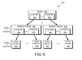
- File system 280maintains various hierarchical data structures, called buffer trees, to keep track of the organization of blocks stored in the aggregate (an exemplary buffer tree and its structure are shown in FIG. 6 ).
- a buffer treemay represent, for example, a volume defined within an aggregate or a file defined within a volume.
- there are generally two relevant buffer treesnamely a container file buffer tree (hereinafter “container buffer tree”) and a user file buffer tree (hereinafter “user buffer tree”).
- the user buffer treerepresents the particular file
- the container buffer treerepresents the volume which contains the file.
- the user buffer treeis used to locate blocks in a file in response to a client-initiated read or write request.
- the buffer treeincludes data blocks. Some of these blocks contain actual data—these are referred to as “direct blocks” (e.g., data blocks 606 ). Some blocks in a buffer tree simply contain pointers to other blocks—these are referred to as “indirect blocks” (e.g., indirect blocks 604 ). There can be multiple levels of indirect blocks in a buffer tree (one level of indirect blocks, Level 1, is shown for simplicity only). There is one level (Level 0) of direct blocks, which is the lowest level of the buffer tree.
- a fileis represented in the write-anywhere file system as an mode data structure adapted for storage on the disks 130 .
- the root of the buffer treeis known as an “mode” ( 602 ), which is a metadata structure that contains metadata about the file.
- the information stored in the metadata section of each modedescribes the file and, as such, includes the type (e.g., regular, directory, virtual disk) of file, the size of the file, time stamps (e.g., access and/or modification) for the file and ownership, i.e., user identifier and group ID, of the file.
- the data section of a regular on-disk modemay include file system data or pointers, the latter referencing, e.g., 4 k bytes (kB) data blocks on disk used to store the file system data.
- An mode and indirect block in the user buffer tree shown in FIG. 6includes a pair of associated pointers (e.g., pointers 605 ) for a lower level block that it references, namely, a Physical Volume Block Number in an aggregate (PVBN) and a Virtual Volume Block Number (VVBN).
- the VVBNis an address of the block in the volume. Every mode and indirect block in the container buffer tree also includes PVBN for every lower level block that it references.
- the file system 280When accessing a data block in response to servicing an external client read request, the file system 280 specifies VVBN that is translated at the file system 280 into a PVBN location on a particular disk within a RAID group of the physical volume. Each block in the VVBN space and in the PVBN space is typically fixed, e.g., 4 kB, in size.
- the disk location specified by the RAID system 236is further translated by the disk driver system 235 of the storage operating system 200 into a plurality of sectors (e.g., a 4 kB block which a RAID header translates to 8 or 9 disk sectors of 512 or 520 bytes) on the specified disk so that the data block will be written to a disk at the next consistency point.
- a consistency pointis the recurring event at which any new or modified data that has been temporarily cached in the storage system's buffer cache 170 is committed to long-term storage (e.g., disks).
- a consistency pointtypically occurs periodically, i.e., from time to time (e.g., every 10 seconds) or in response to a predetermined condition occurring (e.g., a specified percentage of memory is full of “dirty” data).
- a retrieved data blockmay be loaded from disk 130 into the buffer cache 170 .
- its corresponding in-core structureembeds the on-disk structure.
- the in-core structureis a block of memory that stores the on-disk structure plus additional information needed to manage data in the memory.
- Additional informationmay include, e.g., a “dirty” bit.
- a “dirty” bitAfter data in the mode (or block) is updated or modified as instructed by, e.g., a write operation, the modified data are marked “dirty” using the dirty bit so that the mode (block) can be subsequently “flushed” (stored) to disk.
- the file system 280also includes a monitoring module 260 and a disk cooling module 284 .
- Monitoring module 260is configured to compute average latency across an aggregate. Monitoring module 260 also periodically compares the average latency to the target latency and causes reduction of access frequency of some of the disks within an aggregate to the point where they can be paused without causing a large increase in average latency. Monitoring module 260 determines how many disks to cool and requests a disk management system 240 to select disks for cooling.
- the disk cooling module 284reduces access frequency to the disks selected for cooling and prevents write requests from going to these disks.
- disk cooling module 284provides an indication in a disk data structure (not shown) that a disk is in a cooling mode (i.e., data blocks from that disk are copied to other disks). For example, during an access operation, disk cooling module 284 sets a flag next to the data block retrieved from the cooling disk to indicate that the data block is to be written to a new location.
- File system 280further includes a write allocation module 282 configured to allocate free blocks on a disk to store data.
- a write allocation module 282configured to allocate free blocks on a disk to store data.
- data blocks that are currently occupied by any data or metadataare called “allocated data blocks.”
- Data blocks that are not occupied by any data or metadataare called “free data blocks” or “unallocated data blocks.”
- Write allocation module 282goes through the data blocks in the buffer cache 170 and identifies data blocks having a flag set next to them. Write allocation module 282 then writes these data blocks to new on-disk locations.
- a cooling diskis prevented from being returned to the write allocation module 282 when write allocation module 282 requests that a disk be provided to allocate data blocks.
- the write allocation module 282uses a block allocation data structure, such as for example, block allocation data structure 286 , to select free data blocks within its VVBN space to which to write new data.
- data structure 286is implemented as a bitmap in which a value of “1” may indicate that a data block is allocated and a value of “0” (zero) may indicate that a data block is not allocated.
- a value of “1”may indicate that a data block is allocated
- 0zero
- the disk management system 240 of the storage operating system 200includes RAID system 236 and disk driver system 235 . According to an embodiment of the present invention, disk management system 240 selects disks for cooling in response to a request received from monitoring module 260 . In one implementation, disk management system 240 chooses a disk(s) to cool based on a disk access frequency.
- RAID system 236(also referred to herein as a “storage module”) manages the storage and retrieval of the information to and from the disks in accordance with input/output (I/O) operations.
- the RAID system 236is also responsible for parity operations in the storage system 120 .
- RAID system 236maintains data structures for each RAID group (these data structures are not shown in FIG. 3 ).
- a data structure for a RAID grouppoints to one or more disk data structures that identify disks included in the RAID group.
- a disk data structure(not shown in FIG. 3 ) may include a type of a disk, the disk's serial number, the disk's location, the disk's size, and a handle to identify the disk that is used when sending requests to disk driver system 235 .
- RAID system 236can be a software module executed on the storage system 120 .
- RAID system 236can be a separate controller implemented as hardware.
- RAID system 236may implement various protocols, such as, for example, RAID-4, RAID-5, or RAID-DP.
- Disk driver system 235allows storage system 120 to communicate with the disks 130 .
- the disk driver system 235may implement a lower-level storage device access protocol, such as Fibre Channel Protocol (FCP) or SCSI.
- Disk driver system 235monitors individual disk utilization, an access frequency rate of individual disks, as well as different types of errors received from the disks. Such errors are conventionally generated as provided by disk drives' manufacturers. Further, the monitored information may include a number of read and write requests received by each of the selected disks, the amount of data read from each of the selected disk, and the amount of data written to each of the selected disk. Disk driver system 235 may also keep information about power consumed by the selected disks. The monitored data may be kept in data structures (not shown in FIG. 2 ) in memory 124 of the storage system 120 .
- disk driver system 235is further configured to pause cooling disks and to restart the disks.
- “pausing” the diskmeans sending a command by the disk driver system 235 to a disk to remove power from a spindle of the disk so that platters storing data cannot be accessed on a disk.
- “Restarting” the diskmeans sending a command to a disk to provide power to a spindle of the disk so that platters can be accessed on that disk.
- a command sent to a diskdepends on the type of the disk. Commands may be sent, for example, using the FC protocol and Advanced Technology Attachment (ATA) protocol depending on the type of the disk.
- ATAAdvanced Technology Attachment
- disk driver system 235prior to pausing a disk, disk driver system 235 performs a cost-effectiveness analysis to determine whether pausing the disk would save energy.
- access frequency for a cooling diskis compared to the lower of the two parameters: a spin down rate and target latency.
- a spin down rateis a parameter provided by a disk manufacturer indicating the maximum access frequency at which pausing the disk is economically desirable.
- the target latencyis a parameter indicating latency that is desirable for the aggregate to maintain.
- access frequency for a cooling diskis compared to a spin down rate to determine whether it is economically desirable to pause the disks to reduce power consumption. If the disk access frequency is higher than the spin down rate, then pausing and resuming the disk would occur so frequently that energy consumption required to restart the disk would exceed the amount of energy saved as a result of pausing the disk. Under these circumstances, pausing the disk is not economically desirable.
- Storage operating system 200further includes the protocol module 232 configured to decode incoming client requests or encode outgoing response to the client requests in the appropriate protocol.
- Protocol module 232implements one or more of various high-level network protocols, such as Network File System (NFS), Common Internet File System (CIFS), Hypertext Transfer Protocol (HTTP) and/or Transmission Control Protocol/Internet Protocol (TCP/IP).
- NFSNetwork File System
- CIFSCommon Internet File System
- HTTPHypertext Transfer Protocol
- TCP/IPTransmission Control Protocol/Internet Protocol
- the network access module 233includes one or more drivers which implement one or more lower-level protocols to communicate over the network, such as Ethernet.
- the protocol module 232 and the associated network access module 233allow the storage system 120 to communicate with client 110 .
- Monitoring module 260periodically monitors performance of disks in an aggregate and determines how many disks to cool based on disks' performance.
- a userenters, via user console 190 , target latency (L T ).
- the target latencycan be provided by an external agent (not shown in FIGS. 1-6 ).
- the target latencyis a maximum threshold of average latency desirable for the aggregate to maintain.
- the target latencymay be expressed, for example, in milliseconds (ms).
- Monitoring module 260receives L T , at step 305 .
- Monitoring module 260periodically compares (at step 320 ) L current avg with L T . If L current avg exceeds the target latency, it indicates that as a result of cooling the disks, the current load of requests cannot be handled by a fewer number of disks without exceeding the target latency. As a result, monitoring module 260 stops cooling the disks (step 330 ) (the details of the process for cooling the disks is described herein in a “Disk Cooling Process” section of this disclosure).
- Monitoring module 260periodically computes (at step 335 ) target utilization, P T based on the target latency L T , current utilization P current , and current average latency L current avg to determine the number of disks in the storage system 120 that need to remain active (e.g., able to satisfy the current load).
- Current utilization for the set of disks P currentis computed by monitoring module 260 using utilization of each disk (provided by disk management system 240 ).
- Current utilization (P current ) fractionP represents a action of time disks in set of disks are servicing client requests averaged over the number of disks in the set of disks. Thus, if there are 5 disks, and utilization of each disk is as follows: 50%, 75%, 25%, 25%, and 75%, current utilization is equal 50%.
- a value for target utilizationcan be provided to the storage system via the user console (shown in FIG. 1 ).
- monitoring module 260can determine the number of active disks D T (e.g., disks capable of serving requests) that the storage system 120 needs.
- D TD current *P current /P T. ; wherein D current represents the number of disks that are currently active.
- monitoring module 260requests disk management system 240 to select a number of disks Dc to cool based on the disks' access frequency.
- diskscan be selected for cooling based on other parameters.
- alternative embodimentscontemplate that rather than cooling individual disks in the aggregate, cooling can be done at the granularity of RAID groups. As a result, all disks in a RAID group are placed in a cooling mode (as will be described below in reference to the “Disk Cooling Process”).
- Disk cooling module 284receives from disk management system 240 , IDs of the disks selected for cooling. Disk cooling module 284 records in a data structure (not shown in FIGS. 1-6 ) which disks are to be cooled (at step 350 ). Disk cooling module 284 uses the recorded information to determine whether a data block that is retrieved from a disk and stored in buffer cache 170 is from a cooling disk. If the retrieved data block is from the cooling disk, disk cooling module 284 sets a flag next to the data block to indicate that the data block should be written to new on-disk locations (step 360 ). In one implementation, disk cooling module 284 indicates that the retrieved data block is “dirty.”
- the access frequency for the selected disksare reduced by suppressing write requests to the disks selected for cooling (step 370 ).
- the write allocation module 282requests a free block on a disk to store data and then asks for a new disk from which to allocate data blocks.
- the disk cooling module 284prevents an ID of a cooling disk from being returned to the write allocation module 282 in response to the write allocation module 282 issuing a request for a disk to allocate data blocks.
- write requestscan be suppressed from going to individual disks or to an entire RAID group that includes selected disks.
- FIG. 4it illustrates steps performed by write allocation module 282 when it writes data blocks from the cooling disk(s) at new locations.
- Write allocation module 282periodically identifies data blocks marked as “dirty” within buffer cache 170 (step 410 ).
- write allocation module 282determines new on-disk locations (i.e., new PVBNs) for those blocks and writes the data blocks to new locations (step 430 ).
- new on-disk locationsi.e., new PVBNs
- the processthen updates the block allocation data structure 286 (see FIG. 2 ) to reflect that the PVBNs corresponding to the new locations are now in use by the file system 280 .
- a block to be movedwill be considered dirty in VBN space (the aggregate) but not in VVBN space (the volume).
- Write allocation module 282then updates VBN in a container buffer tree (step 440 ).
- FIG. 4occurs at each consistency point and is described in the context of moving data blocks to other locations as a result of servicing “normal read requests”, e.g., requests initiated by the clients externally to the storage system that the system satisfies in order to provide data to its clients.
- “normal read requests”e.g., requests initiated by the clients externally to the storage system that the system satisfies in order to provide data to its clients.
- FIG. 4illustrates only those operations which relate to the technique introduced here and does not list every operation that may occur at a consistency point.
- datacan be relocated during read requests initiated internally, for example, as part of the storage system's maintenance, such as during snapshot deletion to provide more available storage space.
- a snapshotis a persistent point in time (PPT) image of the active file system that enables quick recovery of data after data has been corrupted, lost, or altered. Snapshots can be created by copying the data at each predetermined point in time to form a consistent image, or virtually, by using a pointer to form the image of the data.
- a summary map of the file system(not shown in FIG. 2 ) indicates which blocks in the volume are used by snapshots. As a result of snapshot deletion, disk driver system 235 initiates internal read requests to read the summary map.
- data blockscan be moved independently of client-initiated read operations during a background scan process initiated by RAID system 236 .
- disk cooling module 284may select a segment of blocks on the disks caused to be cooled to relocate to other disks.
- a segmentrefers to a particular number of consecutive blocks across a disk in a RAID group (i.e., a “stripe” across a RAID group).
- Disk cooling module 284then reads that segment from the RAID system 236 and determines (using their PVBNs) which blocks in the segment to relocate. The process then marks those blocks as “dirty”, so that they will be relocated at the next consistency point. This can be done, for example, by setting an appropriate flag or a bit for each block to be moved.
- Disk driver system 235periodically receives (at step 375 ) target latency (L T ) from monitoring module 260 and makes a determination whether it is economically desirable to pause a cooling disk(s) (step 380 ).
- disk driver system 235compares access frequency for a cooling disk to a lower of the two parameters: spin down rate for the disk and L T (at step 380 ).
- a spin down ratecan be coded into the system.
- the calculationtakes into account the time it takes to pause and restart the disks. It also takes into account any energy and reliability costs for cycling disks in this manner.
- a disknormally consumes energy E 1 during the time T it takes to pause the disk, but it consumes 2*E 1 if it is paused and then restarted. It would not save energy to pause such a disk until the average access time reached 2T, even if system latency targets were met.
- a policyis such that a disk could be paused and restarted only N times over a lifetime 1 , if the access rate of a disk were higher than N/1, it would not be cost-effective to pause the disk.
- disk driver system 235causes the disk to pause (at step 390 ).
- the storage system 120 as a wholeis processing N requests a second, at an average latency of Lcurrent avg.
- the latency of the requests sent to that diskwill increase from approximately L to the time (S) it takes to restart the disk to serve the request.
- the access frequency of the disk that will be pausedis R
- the total increase in latencywill be S*R
- the increase in the average latencywill be S*R/N. It will be cost-effective to pause the disk if the increase in the average latency remains less that the target latency, as shown by the equation below: L T >L+S*R/N R ⁇ N *( L T ⁇ L )/ S
- disk driver system 235sends a command to the disk to pause.
- the choice of the commanddepends on the type of disk. For example, disk driver system 235 may send a SCSI command “Stop” to pause a disk.
- the “Stop” commandis also supported by FC and Serial Attached SCSI (SAS) drives. Disk's components that pause and restart the disk are described in more detail in reference to FIG. 5 .
- disk driver system 235compares the access frequency to a spin down rate. If, as a result of the comparison, access frequency rate for a disk to be paused is above the spin down rate, the disk is not paused until the access frequency drops below the spin down rate for that disk. Once the access frequency drops below the spin down rate, disk driver system 235 pauses the disk.
- FIG. 5it illustrates components residing on each disk 130 within a RAID group (such as RAID group 160 shown in FIG. 1 ). These components are configured to execute commands received from disk driver system 235 .
- Disk 130includes a disk memory 520 and a disk controller 510 , which implements a command executing module 530 .
- command executing module 530is implemented as firmware embedded into a hardware device, such as controller 510 .
- command executing module 520can be implemented as software stored in the disk memory 530 .
- Command executing module 520is configured to execute various commands received from disk driver system 235 .
- a received commandis, for example, a SCSI command “Stop”
- the diskwill pause.
- a spindle of the diskstops rotating, thereby reducing power consumption by the aggregate.
- commands that require accessing data on the disksuch as “read” and “write” commands, are not executed.
- command executing module 520returns an error indicating that it not ready to execute the command.
- disk driver system 235When a read request directed to a disk that has been paused arrives, disk driver system 235 sends a command to the disk to restart the disk so that the request can be served.
- commandcan be a “Start” command provided by SCSI.
- disk cooling module 284continues cooling the disks that have been paused. Furthermore, monitoring module 280 periodically compares target latency with the current average latency for the aggregate. If the current average latency exceeds the target latency, monitoring module 280 causes the disks to be restarted again. If the current average latency still remains above the target latency after all the disks in the aggregate have been re-enabled, disk cooling module 284 re-enables write requests going the previously paused RAID group. In one implementation, when write allocation module 282 requests a disk to allocate data blocks, the ID of the cooling disk is provided to the write allocation module 282 . Over time, re-enabling these previously cooled disks would increase the load on these disks and decrease the load on the remaining disks.
- embodiments of the present inventionprovide various mechanisms for reducing access frequency of some disks in an aggregate by copying data blocks from those disks to other disks and causing the disks with the reduced access frequency to pause. Pausing selected disks in the aggregate advantageously reduces power consumption by the aggregate.
- a person of ordinary skill in the artwould understand that parameters other than latency and utilization can be used to measure the system's performance in the context of the present invention.
- a system administratormay specify target power consumption by an aggregate (in effect, specifying the number of disks to pause). The system would cool the disks with the goal of minimizing average latency under the power consumption constraint.
- a user or an external policy engine that monitors performance of the storage system 120may designate disk drives to cool.
- the present inventionhas been described in the context of causing the disks to pause in the primary storage (e.g., disks that store mission-critical data), a person of ordinary skill in the art would understand the present invention is also applicable to causing the disks to pause in archive systems, such as archive system 180 shown in FIG. 1 .
- storage systemprioritizes which disks to pause.
- teachings of this inventioncan be adapted to a variety of storage system architectures including, but not limited to, a network-attached storage environment, and storage area network.
- storage systemshould therefore be taken broadly to include such arrangements in addition to any subsystems configured to perform a storage function and associated with other equipment or system.
- the present inventioncan be implemented by an apparatus for performing the operations herein.
- This apparatusmay be specially constructed for the required purposes or it may comprise a machine, such as a general-purpose computer selectively activated or reconfigured by a computer program (such as a collection of instructions for execution by a machine or processor for example) stored in the computer.
- a computer programmay be stored in a computer readable storage medium, such as, but not limited to any type of disk including floppy disks, optical disks, magnetic optical disks, read-only memories, random access memories, EPROMS, EEPROMS, magnetic or optical cards or any type of media suitable for storing physical (e.g. electronic) constructions and each coupled to a computer system bus. Each of these media may be coupled to a computer system bus through use of an appropriate device for reading and or for writing the media.
Landscapes
- Engineering & Computer Science (AREA)
- Theoretical Computer Science (AREA)
- Physics & Mathematics (AREA)
- General Engineering & Computer Science (AREA)
- General Physics & Mathematics (AREA)
- Human Computer Interaction (AREA)
- Power Sources (AREA)
Abstract
Description
Lcurrent avg=Lr/N+Lavg previous(N−1)/N,
wherein Lr is the time during which the last request was served. Lr can be obtained by
Lcurrent avg=5/10+4(10−1)/10=0.5+3.6=4.1 ms
PT=1−Lcurrent avg(1−Pcurrent)/LT.
PT=1−5*(1−50%)/10 ms=1−25%=75%.
DT=Dcurrent*Pcurrent/PT.;
wherein Dcurrentrepresents the number of disks that are currently active.
Thus, if Dcurrent=10, Pcurrent=50% and PT=75%,
DT=10 * 0.5/0.75=6.6. This indicates that the target number of disks in the system that have to be active is 7. DTcan be used to determine the number of disks (Dc) that can be selected for cooling as follows:
DC=Dcurrent−DT.
LT>L+S*R/N
R<N*(LT−L)/S
Claims (23)
Priority Applications (1)
| Application Number | Priority Date | Filing Date | Title |
|---|---|---|---|
| US11/692,589US8312214B1 (en) | 2007-03-28 | 2007-03-28 | System and method for pausing disk drives in an aggregate |
Applications Claiming Priority (1)
| Application Number | Priority Date | Filing Date | Title |
|---|---|---|---|
| US11/692,589US8312214B1 (en) | 2007-03-28 | 2007-03-28 | System and method for pausing disk drives in an aggregate |
Publications (1)
| Publication Number | Publication Date |
|---|---|
| US8312214B1true US8312214B1 (en) | 2012-11-13 |
Family
ID=47114646
Family Applications (1)
| Application Number | Title | Priority Date | Filing Date |
|---|---|---|---|
| US11/692,589Active2031-01-31US8312214B1 (en) | 2007-03-28 | 2007-03-28 | System and method for pausing disk drives in an aggregate |
Country Status (1)
| Country | Link |
|---|---|
| US (1) | US8312214B1 (en) |
Cited By (7)
| Publication number | Priority date | Publication date | Assignee | Title |
|---|---|---|---|---|
| US20140006816A1 (en)* | 2012-06-29 | 2014-01-02 | Fujitsu Limited | Control apparatus, control method, and computer product |
| US8868954B1 (en)* | 2013-05-21 | 2014-10-21 | Microsoft Corporation | Low cost storage for rarely read data |
| US20150381506A1 (en)* | 2010-10-29 | 2015-12-31 | Amazon Technologies, Inc. | Adding latency to improve perceived performance |
| US9442668B1 (en)* | 2013-08-29 | 2016-09-13 | Western Digital Technologies, Inc. | Adaptive power management control with performance feedback |
| US10771565B2 (en) | 2010-12-15 | 2020-09-08 | Amazon Technologies, Inc. | Sending application input commands over a network |
| US11442629B2 (en)* | 2020-07-15 | 2022-09-13 | International Business Machines Corporation | I/O performance in a storage system |
| US20240256372A1 (en)* | 2016-09-07 | 2024-08-01 | Pure Storage, Inc. | Temporarily Limiting I/O Operations To A Storage Device |
Citations (71)
| Publication number | Priority date | Publication date | Assignee | Title |
|---|---|---|---|---|
| US4156907A (en) | 1977-03-02 | 1979-05-29 | Burroughs Corporation | Data communications subsystem |
| US4399503A (en) | 1978-06-30 | 1983-08-16 | Bunker Ramo Corporation | Dynamic disk buffer control unit |
| US4517663A (en) | 1979-09-04 | 1985-05-14 | Fujitsu Fanuc Limited | Method of rewriting data in non-volatile memory, and system therefor |
| US4598357A (en) | 1980-11-14 | 1986-07-01 | Sperry Corporation | Cache/disk subsystem with file number for recovery of cached data |
| US4688221A (en) | 1983-12-28 | 1987-08-18 | Hitachi, Ltd. | Error recovery method and apparatus |
| US4698808A (en) | 1984-12-14 | 1987-10-06 | International Business Machines Corporation | Method for detecting intermittent error in volatile memory |
| US4761785A (en) | 1986-06-12 | 1988-08-02 | International Business Machines Corporation | Parity spreading to enhance storage access |
| US4805090A (en) | 1985-09-27 | 1989-02-14 | Unisys Corporation | Peripheral-controller for multiple disk drive modules having different protocols and operating conditions |
| US4817035A (en) | 1984-03-16 | 1989-03-28 | Cii Honeywell Bull | Method of recording in a disk memory and disk memory system |
| US4837675A (en) | 1981-10-05 | 1989-06-06 | Digital Equipment Corporation | Secondary storage facility empolying serial communications between drive and controller |
| US4864497A (en) | 1988-04-13 | 1989-09-05 | Digital Equipment Corporation | Method of integrating software application programs using an attributive data model database |
| WO1989010594A1 (en) | 1988-04-22 | 1989-11-02 | Amdahl Corporation | A file system for a plurality of storage classes |
| US4896259A (en) | 1984-09-07 | 1990-01-23 | International Business Machines Corporation | Apparatus for storing modifying data prior to selectively storing data to be modified into a register |
| US4899342A (en) | 1988-02-01 | 1990-02-06 | Thinking Machines Corporation | Method and apparatus for operating multi-unit array of memories |
| US4989206A (en) | 1988-06-28 | 1991-01-29 | Storage Technology Corporation | Disk drive memory |
| US5088081A (en) | 1990-03-28 | 1992-02-11 | Prime Computer, Inc. | Method and apparatus for improved disk access |
| US5124987A (en) | 1990-04-16 | 1992-06-23 | Storage Technology Corporation | Logical track write scheduling system for a parallel disk drive array data storage subsystem |
| US5155835A (en) | 1990-11-19 | 1992-10-13 | Storage Technology Corporation | Multilevel, hierarchical, dynamically mapped data storage subsystem |
| USRE34100E (en) | 1987-01-12 | 1992-10-13 | Seagate Technology, Inc. | Data error correction system |
| US5163131A (en) | 1989-09-08 | 1992-11-10 | Auspex Systems, Inc. | Parallel i/o network file server architecture |
| US5274799A (en) | 1991-01-04 | 1993-12-28 | Array Technology Corporation | Storage device array architecture with copyback cache |
| US5426747A (en) | 1991-03-22 | 1995-06-20 | Object Design, Inc. | Method and apparatus for virtual memory mapping and transaction management in an object-oriented database system |
| US5568629A (en) | 1991-12-23 | 1996-10-22 | At&T Global Information Solutions Company | Method for partitioning disk drives within a physical disk array and selectively assigning disk drive partitions into a logical disk array |
| US5581724A (en) | 1992-10-19 | 1996-12-03 | Storage Technology Corporation | Dynamically mapped data storage subsystem having multiple open destage cylinders and method of managing that subsystem |
| US5819292A (en) | 1993-06-03 | 1998-10-06 | Network Appliance, Inc. | Method for maintaining consistent states of a file system and for creating user-accessible read-only copies of a file system |
| US5828876A (en) | 1996-07-31 | 1998-10-27 | Ncr Corporation | File system for a clustered processing system |
| US5944789A (en) | 1996-08-14 | 1999-08-31 | Emc Corporation | Network file server maintaining local caches of file directory information in data mover computers |
| US5948110A (en) | 1993-06-04 | 1999-09-07 | Network Appliance, Inc. | Method for providing parity in a raid sub-system using non-volatile memory |
| US5963962A (en) | 1995-05-31 | 1999-10-05 | Network Appliance, Inc. | Write anywhere file-system layout |
| US5987477A (en) | 1997-07-11 | 1999-11-16 | International Business Machines Corporation | Parallel file system and method for parallel write sharing |
| US6032224A (en) | 1996-12-03 | 2000-02-29 | Emc Corporation | Hierarchical performance system for managing a plurality of storage units with different access speeds |
| US6131252A (en) | 1997-04-09 | 2000-10-17 | Volkswagen Ag | Connecting arrangement for the exhaust gas system of a motor vehicle |
| US6185655B1 (en) | 1998-01-22 | 2001-02-06 | Bull, S.A. | Computer system with distributed data storing |
| US6192481B1 (en)* | 1998-08-18 | 2001-02-20 | International Business Machines Corporation | Structure and method for power sequencing of disk drives in a computer system |
| US6314503B1 (en) | 1998-12-30 | 2001-11-06 | Emc Corporation | Method and apparatus for managing the placement of data in a storage system to achieve increased system performance |
| US6324620B1 (en) | 1998-07-23 | 2001-11-27 | International Business Machines Corporation | Dynamic DASD data management and partitioning based on access frequency utilization and capacity |
| US20020103969A1 (en) | 2000-12-12 | 2002-08-01 | Hiroshi Koizumi | System and method for storing data |
| US20020124137A1 (en) | 2001-01-29 | 2002-09-05 | Ulrich Thomas R. | Enhancing disk array performance via variable parity based load balancing |
| US6457021B1 (en) | 1998-08-18 | 2002-09-24 | Microsoft Corporation | In-memory database system |
| WO2002093298A2 (en) | 2001-05-14 | 2002-11-21 | Diva Systems Corporation | Modular storage server architecture with dynamic datamanagement |
| US6516380B2 (en) | 2001-02-05 | 2003-02-04 | International Business Machines Corporation | System and method for a log-based non-volatile write cache in a storage controller |
| US20030056058A1 (en) | 2001-09-17 | 2003-03-20 | Alistair Veitch | Logical volume data migration |
| US6636879B1 (en) | 2000-08-18 | 2003-10-21 | Network Appliance, Inc. | Space allocation in a write anywhere file system |
| US6643654B1 (en) | 2001-06-25 | 2003-11-04 | Network Appliance, Inc. | System and method for representing named data streams within an on-disk structure of a file system |
| US20030212872A1 (en) | 2002-05-08 | 2003-11-13 | Brian Patterson | Distributing workload evenly across storage media in a storage array |
| US20040030668A1 (en) | 2002-08-09 | 2004-02-12 | Brian Pawlowski | Multi-protocol storage appliance that provides integrated support for file and block access protocols |
| US20040139167A1 (en) | 2002-12-06 | 2004-07-15 | Andiamo Systems Inc., A Delaware Corporation | Apparatus and method for a scalable network attach storage system |
| US20040172503A1 (en) | 2003-02-28 | 2004-09-02 | Arif Merchant | Adjustable storage system |
| US6795904B1 (en) | 2002-03-28 | 2004-09-21 | Hewlett-Packard Development Company, L.P. | System and method for improving performance of a data backup operation |
| US20040193397A1 (en)* | 2003-03-28 | 2004-09-30 | Christopher Lumb | Data storage system emulation |
| US20040210724A1 (en) | 2003-01-21 | 2004-10-21 | Equallogic Inc. | Block data migration |
| US6865650B1 (en) | 2000-09-29 | 2005-03-08 | Emc Corporation | System and method for hierarchical data storage |
| US20050240742A1 (en) | 2004-04-22 | 2005-10-27 | Apple Computer, Inc. | Method and apparatus for improving performance of data storage systems |
| US20060004957A1 (en) | 2002-09-16 | 2006-01-05 | Hand Leroy C Iii | Storage system architectures and multiple caching arrangements |
| US20060031287A1 (en) | 2001-01-29 | 2006-02-09 | Ulrich Thomas R | Systems and methods for load balancing drives and servers |
| US7035972B2 (en) | 2002-09-03 | 2006-04-25 | Copan Systems, Inc. | Method and apparatus for power-efficient high-capacity scalable storage system |
| US20060112242A1 (en) | 2004-11-19 | 2006-05-25 | Mcbride Gregory E | Application transparent autonomic data replication improving access performance for a storage area network aware file system |
| WO2006055765A2 (en) | 2004-11-19 | 2006-05-26 | Network Appliance, Inc. | System and method for real-time balancing of user workload across multiple storage systems with shared back end storage |
| US20060206675A1 (en) | 2005-03-11 | 2006-09-14 | Yoshitaka Sato | Storage system and data movement method |
| US20060259686A1 (en) | 2005-05-13 | 2006-11-16 | Fujitsu Limited | Storage control method, program, and apparatus |
| US7194597B2 (en) | 2001-03-30 | 2007-03-20 | Intel Corporation | Method and apparatus for sharing TLB entries |
| US20070088702A1 (en) | 2005-10-03 | 2007-04-19 | Fridella Stephen A | Intelligent network client for multi-protocol namespace redirection |
| US20070168633A1 (en) | 2006-01-19 | 2007-07-19 | English Robert M | Method and apparatus for defragmentation and for detection of relocated blocks |
| US7263590B1 (en) | 2003-04-23 | 2007-08-28 | Emc Corporation | Method and apparatus for migrating data in a computer system |
| US7281108B2 (en) | 2002-12-10 | 2007-10-09 | Emc Corporation | Method and apparatus for managing migration of data in a computer system |
| US20070255897A1 (en) | 2006-04-26 | 2007-11-01 | Mcnutt Bruce | Apparatus, system, and method for facilitating physical disk request scheduling |
| US20070288712A1 (en) | 2006-06-09 | 2007-12-13 | Hitachi, Ltd. | Storage apparatus and storage apparatus control method |
| US7406365B2 (en)* | 2006-03-31 | 2008-07-29 | Intel Corporation | Power manager with selective load reduction |
| US7409494B2 (en) | 2004-04-30 | 2008-08-05 | Network Appliance, Inc. | Extension of write anywhere file system layout |
| US20080263259A1 (en) | 2007-04-23 | 2008-10-23 | Microsoft Corporation | Hints model for optimization of storage devices connected to host and write optimization schema for storage devices |
| US20080270706A1 (en) | 2007-04-27 | 2008-10-30 | Fair Robert L | Block Reallocation Planning During Read-Ahead Processing |
- 2007
- 2007-03-28USUS11/692,589patent/US8312214B1/enactiveActive
Patent Citations (77)
| Publication number | Priority date | Publication date | Assignee | Title |
|---|---|---|---|---|
| US4156907A (en) | 1977-03-02 | 1979-05-29 | Burroughs Corporation | Data communications subsystem |
| US4399503A (en) | 1978-06-30 | 1983-08-16 | Bunker Ramo Corporation | Dynamic disk buffer control unit |
| US4517663A (en) | 1979-09-04 | 1985-05-14 | Fujitsu Fanuc Limited | Method of rewriting data in non-volatile memory, and system therefor |
| US4598357A (en) | 1980-11-14 | 1986-07-01 | Sperry Corporation | Cache/disk subsystem with file number for recovery of cached data |
| US4837675A (en) | 1981-10-05 | 1989-06-06 | Digital Equipment Corporation | Secondary storage facility empolying serial communications between drive and controller |
| US4688221A (en) | 1983-12-28 | 1987-08-18 | Hitachi, Ltd. | Error recovery method and apparatus |
| US4817035A (en) | 1984-03-16 | 1989-03-28 | Cii Honeywell Bull | Method of recording in a disk memory and disk memory system |
| US4849929A (en) | 1984-03-16 | 1989-07-18 | Cii Honeywell Bull (Societe Anonyme) | Method of recording in a disk memory and disk memory system |
| US4896259A (en) | 1984-09-07 | 1990-01-23 | International Business Machines Corporation | Apparatus for storing modifying data prior to selectively storing data to be modified into a register |
| US4698808A (en) | 1984-12-14 | 1987-10-06 | International Business Machines Corporation | Method for detecting intermittent error in volatile memory |
| US4805090A (en) | 1985-09-27 | 1989-02-14 | Unisys Corporation | Peripheral-controller for multiple disk drive modules having different protocols and operating conditions |
| US4761785A (en) | 1986-06-12 | 1988-08-02 | International Business Machines Corporation | Parity spreading to enhance storage access |
| US4761785B1 (en) | 1986-06-12 | 1996-03-12 | Ibm | Parity spreading to enhance storage access |
| USRE34100E (en) | 1987-01-12 | 1992-10-13 | Seagate Technology, Inc. | Data error correction system |
| US4899342A (en) | 1988-02-01 | 1990-02-06 | Thinking Machines Corporation | Method and apparatus for operating multi-unit array of memories |
| US4864497A (en) | 1988-04-13 | 1989-09-05 | Digital Equipment Corporation | Method of integrating software application programs using an attributive data model database |
| WO1989010594A1 (en) | 1988-04-22 | 1989-11-02 | Amdahl Corporation | A file system for a plurality of storage classes |
| US4989206A (en) | 1988-06-28 | 1991-01-29 | Storage Technology Corporation | Disk drive memory |
| US5802366A (en) | 1989-09-08 | 1998-09-01 | Auspex Systems, Inc. | Parallel I/O network file server architecture |
| US5931918A (en) | 1989-09-08 | 1999-08-03 | Auspex Systems, Inc. | Parallel I/O network file server architecture |
| US5163131A (en) | 1989-09-08 | 1992-11-10 | Auspex Systems, Inc. | Parallel i/o network file server architecture |
| US5355453A (en) | 1989-09-08 | 1994-10-11 | Auspex Systems, Inc. | Parallel I/O network file server architecture |
| US5088081A (en) | 1990-03-28 | 1992-02-11 | Prime Computer, Inc. | Method and apparatus for improved disk access |
| US5124987A (en) | 1990-04-16 | 1992-06-23 | Storage Technology Corporation | Logical track write scheduling system for a parallel disk drive array data storage subsystem |
| US5155835A (en) | 1990-11-19 | 1992-10-13 | Storage Technology Corporation | Multilevel, hierarchical, dynamically mapped data storage subsystem |
| US5274799A (en) | 1991-01-04 | 1993-12-28 | Array Technology Corporation | Storage device array architecture with copyback cache |
| US5426747A (en) | 1991-03-22 | 1995-06-20 | Object Design, Inc. | Method and apparatus for virtual memory mapping and transaction management in an object-oriented database system |
| US5568629A (en) | 1991-12-23 | 1996-10-22 | At&T Global Information Solutions Company | Method for partitioning disk drives within a physical disk array and selectively assigning disk drive partitions into a logical disk array |
| US5581724A (en) | 1992-10-19 | 1996-12-03 | Storage Technology Corporation | Dynamically mapped data storage subsystem having multiple open destage cylinders and method of managing that subsystem |
| US6289356B1 (en) | 1993-06-03 | 2001-09-11 | Network Appliance, Inc. | Write anywhere file-system layout |
| US5819292A (en) | 1993-06-03 | 1998-10-06 | Network Appliance, Inc. | Method for maintaining consistent states of a file system and for creating user-accessible read-only copies of a file system |
| US5948110A (en) | 1993-06-04 | 1999-09-07 | Network Appliance, Inc. | Method for providing parity in a raid sub-system using non-volatile memory |
| US5963962A (en) | 1995-05-31 | 1999-10-05 | Network Appliance, Inc. | Write anywhere file-system layout |
| US5828876A (en) | 1996-07-31 | 1998-10-27 | Ncr Corporation | File system for a clustered processing system |
| US5944789A (en) | 1996-08-14 | 1999-08-31 | Emc Corporation | Network file server maintaining local caches of file directory information in data mover computers |
| US6032224A (en) | 1996-12-03 | 2000-02-29 | Emc Corporation | Hierarchical performance system for managing a plurality of storage units with different access speeds |
| US6131252A (en) | 1997-04-09 | 2000-10-17 | Volkswagen Ag | Connecting arrangement for the exhaust gas system of a motor vehicle |
| US5987477A (en) | 1997-07-11 | 1999-11-16 | International Business Machines Corporation | Parallel file system and method for parallel write sharing |
| US6185655B1 (en) | 1998-01-22 | 2001-02-06 | Bull, S.A. | Computer system with distributed data storing |
| US6324620B1 (en) | 1998-07-23 | 2001-11-27 | International Business Machines Corporation | Dynamic DASD data management and partitioning based on access frequency utilization and capacity |
| US6457021B1 (en) | 1998-08-18 | 2002-09-24 | Microsoft Corporation | In-memory database system |
| US6192481B1 (en)* | 1998-08-18 | 2001-02-20 | International Business Machines Corporation | Structure and method for power sequencing of disk drives in a computer system |
| US6314503B1 (en) | 1998-12-30 | 2001-11-06 | Emc Corporation | Method and apparatus for managing the placement of data in a storage system to achieve increased system performance |
| US6636879B1 (en) | 2000-08-18 | 2003-10-21 | Network Appliance, Inc. | Space allocation in a write anywhere file system |
| US6865650B1 (en) | 2000-09-29 | 2005-03-08 | Emc Corporation | System and method for hierarchical data storage |
| US20020103969A1 (en) | 2000-12-12 | 2002-08-01 | Hiroshi Koizumi | System and method for storing data |
| US20060031287A1 (en) | 2001-01-29 | 2006-02-09 | Ulrich Thomas R | Systems and methods for load balancing drives and servers |
| US20020124137A1 (en) | 2001-01-29 | 2002-09-05 | Ulrich Thomas R. | Enhancing disk array performance via variable parity based load balancing |
| US6516380B2 (en) | 2001-02-05 | 2003-02-04 | International Business Machines Corporation | System and method for a log-based non-volatile write cache in a storage controller |
| US7194597B2 (en) | 2001-03-30 | 2007-03-20 | Intel Corporation | Method and apparatus for sharing TLB entries |
| WO2002093298A2 (en) | 2001-05-14 | 2002-11-21 | Diva Systems Corporation | Modular storage server architecture with dynamic datamanagement |
| US6643654B1 (en) | 2001-06-25 | 2003-11-04 | Network Appliance, Inc. | System and method for representing named data streams within an on-disk structure of a file system |
| US20030056058A1 (en) | 2001-09-17 | 2003-03-20 | Alistair Veitch | Logical volume data migration |
| US6795904B1 (en) | 2002-03-28 | 2004-09-21 | Hewlett-Packard Development Company, L.P. | System and method for improving performance of a data backup operation |
| US20030212872A1 (en) | 2002-05-08 | 2003-11-13 | Brian Patterson | Distributing workload evenly across storage media in a storage array |
| US20040030668A1 (en) | 2002-08-09 | 2004-02-12 | Brian Pawlowski | Multi-protocol storage appliance that provides integrated support for file and block access protocols |
| US7035972B2 (en) | 2002-09-03 | 2006-04-25 | Copan Systems, Inc. | Method and apparatus for power-efficient high-capacity scalable storage system |
| US20060004957A1 (en) | 2002-09-16 | 2006-01-05 | Hand Leroy C Iii | Storage system architectures and multiple caching arrangements |
| US20040139167A1 (en) | 2002-12-06 | 2004-07-15 | Andiamo Systems Inc., A Delaware Corporation | Apparatus and method for a scalable network attach storage system |
| US7281108B2 (en) | 2002-12-10 | 2007-10-09 | Emc Corporation | Method and apparatus for managing migration of data in a computer system |
| US20040210724A1 (en) | 2003-01-21 | 2004-10-21 | Equallogic Inc. | Block data migration |
| US20040172503A1 (en) | 2003-02-28 | 2004-09-02 | Arif Merchant | Adjustable storage system |
| US20040193397A1 (en)* | 2003-03-28 | 2004-09-30 | Christopher Lumb | Data storage system emulation |
| US7263590B1 (en) | 2003-04-23 | 2007-08-28 | Emc Corporation | Method and apparatus for migrating data in a computer system |
| US20050240742A1 (en) | 2004-04-22 | 2005-10-27 | Apple Computer, Inc. | Method and apparatus for improving performance of data storage systems |
| US7409494B2 (en) | 2004-04-30 | 2008-08-05 | Network Appliance, Inc. | Extension of write anywhere file system layout |
| WO2006055765A2 (en) | 2004-11-19 | 2006-05-26 | Network Appliance, Inc. | System and method for real-time balancing of user workload across multiple storage systems with shared back end storage |
| US20060112242A1 (en) | 2004-11-19 | 2006-05-25 | Mcbride Gregory E | Application transparent autonomic data replication improving access performance for a storage area network aware file system |
| US20060206675A1 (en) | 2005-03-11 | 2006-09-14 | Yoshitaka Sato | Storage system and data movement method |
| US20060259686A1 (en) | 2005-05-13 | 2006-11-16 | Fujitsu Limited | Storage control method, program, and apparatus |
| US20070088702A1 (en) | 2005-10-03 | 2007-04-19 | Fridella Stephen A | Intelligent network client for multi-protocol namespace redirection |
| US20070168633A1 (en) | 2006-01-19 | 2007-07-19 | English Robert M | Method and apparatus for defragmentation and for detection of relocated blocks |
| US7406365B2 (en)* | 2006-03-31 | 2008-07-29 | Intel Corporation | Power manager with selective load reduction |
| US20070255897A1 (en) | 2006-04-26 | 2007-11-01 | Mcnutt Bruce | Apparatus, system, and method for facilitating physical disk request scheduling |
| US20070288712A1 (en) | 2006-06-09 | 2007-12-13 | Hitachi, Ltd. | Storage apparatus and storage apparatus control method |
| US20080263259A1 (en) | 2007-04-23 | 2008-10-23 | Microsoft Corporation | Hints model for optimization of storage devices connected to host and write optimization schema for storage devices |
| US20080270706A1 (en) | 2007-04-27 | 2008-10-30 | Fair Robert L | Block Reallocation Planning During Read-Ahead Processing |
Non-Patent Citations (16)
| Title |
|---|
| Akyurek, Sedat, Placing Replicated Data to Reduce Seek Delays, Department of Computer Science, University of Maryland, UMIACS-TR-91-121, CS-TR-2746, Aug. 1991. |
| Callaghan, B., "NFS Version 3 Protocol Specification", Request for Comments (RFC) 1813 Jun. 1995, 118 pages. |
| Common Internet File System (CIFS) Version: CIFS-Spec 0.9, Storage Networking Industry Association (SNIA), Draft SNIA CIFS Documentation Work Group Work-in-Progress, Revision Date: Mar. 26, 2001, 126 pages. |
| Gait, Jason, Phoenix: A Safe In-Memory File System. Communications of the ACM, 33(1): pp. 81-86, Jan. 1990. |
| Hitz, Dave et al., File System Design for an NFS File Server Appliance, Technical Report 3002, Rev. C395, presented Jan. 19, 1994, 23 pages. |
| Howard, John H, et al., Scale and Performance in a Distributed File System, Carnegie Mellon University, CMU-ITC-87-068, Aug. 5, 1987, 33 pages. |
| Howard, John, H. et al., Scale and performance in a distributed file system, ACM Trans. Computer. System., 6(1), Feb. 1988 pp. 51-81. |
| Kazar, Michael L., Synchronization and Caching Issues in the Andrew File System, Carnegie Mellon University, CMU-ITC88-063, 12 pages, 1988. |
| Miller, Ethan L., et al., RAMA: A File System for Massively Parallel Computers, 12.sup.th IEEE Symposium on Mass Storage Systems, Monterey CA, Apr. 1993, pp. 163-168. |
| Nelson, Michael et al., "Caching in the Sprite Network File System", ACM, Nov. 1987, pp. 3-4. |
| Ousterhout, John et al., Beating the I/O Bottleneck: A Case for Log-Structured File Systems, Technical Report, Computer Science Division, Electrical Engineering and Computer Sciences, University of California at Berkeley, Oct. 30, 1988, 18 pages. |
| Satyanarayanan, M., et al., Coda: A highly available file system for a distributed workstation environment Carnegie Mellon University, CMU-ITC, 1990, 5 pages. |
| Satyanarayanan, M., et al., Coda: A highly available file system for a distributed workstation environment. IEEE Transactions on Computers, 39(4):447-459, 1990. |
| Satyanarayanan, M., Scalable, Secure, and Highly Available Distributed File Access, Computer May 1990: 9-21. |
| U.S. Appl. No. 11/692,589, filed Mar. 2007, English. |
| Weikum, Gerhard, et al., Towards Self-Tuning Memory Management for Data Servers, Data Engineering Journal 22, Feb. 1999 pp. 3-11. |
Cited By (10)
| Publication number | Priority date | Publication date | Assignee | Title |
|---|---|---|---|---|
| US20150381506A1 (en)* | 2010-10-29 | 2015-12-31 | Amazon Technologies, Inc. | Adding latency to improve perceived performance |
| US9705810B2 (en)* | 2010-10-29 | 2017-07-11 | Amazon Technologies, Inc. | Adding latency to improve perceived performance |
| US10771565B2 (en) | 2010-12-15 | 2020-09-08 | Amazon Technologies, Inc. | Sending application input commands over a network |
| US20140006816A1 (en)* | 2012-06-29 | 2014-01-02 | Fujitsu Limited | Control apparatus, control method, and computer product |
| US8868954B1 (en)* | 2013-05-21 | 2014-10-21 | Microsoft Corporation | Low cost storage for rarely read data |
| US9471068B2 (en) | 2013-05-21 | 2016-10-18 | Microsoft Technology Licensing, Llc | Low cost storage for rarely read data |
| US9841774B2 (en) | 2013-05-21 | 2017-12-12 | Microsoft Technology Licensing, Llc | Low cost storage for rarely read data |
| US9442668B1 (en)* | 2013-08-29 | 2016-09-13 | Western Digital Technologies, Inc. | Adaptive power management control with performance feedback |
| US20240256372A1 (en)* | 2016-09-07 | 2024-08-01 | Pure Storage, Inc. | Temporarily Limiting I/O Operations To A Storage Device |
| US11442629B2 (en)* | 2020-07-15 | 2022-09-13 | International Business Machines Corporation | I/O performance in a storage system |
Similar Documents
| Publication | Publication Date | Title |
|---|---|---|
| US7984259B1 (en) | Reducing load imbalance in a storage system | |
| JP5260610B2 (en) | Virtual disk drive system and method | |
| US8250335B2 (en) | Method, system and computer program product for managing the storage of data | |
| US8667180B2 (en) | Compression on thin provisioned volumes using extent based mapping | |
| US9418015B2 (en) | Data storage within hybrid storage aggregate | |
| US8762667B2 (en) | Optimization of data migration between storage mediums | |
| US8566550B2 (en) | Application and tier configuration management in dynamic page reallocation storage system | |
| US7814351B2 (en) | Power management in a storage array | |
| EP2531922B1 (en) | Dynamic management of destage tasks in a storage controller | |
| US8312214B1 (en) | System and method for pausing disk drives in an aggregate | |
| US9323655B1 (en) | Location of data among storage tiers | |
| US20140122818A1 (en) | Storage apparatus and method for controlling storage apparatus | |
| US20140281131A1 (en) | Systems and methods for persistent cache logging | |
| US8793226B1 (en) | System and method for estimating duplicate data | |
| US20050256999A1 (en) | Dynamic loading of virtual volume data in a virtual tape server | |
| US9965381B1 (en) | Indentifying data for placement in a storage system | |
| US8935304B2 (en) | Efficient garbage collection in a compressed journal file | |
| JP2007156597A (en) | Storage device | |
| CN101751470B (en) | System and method for storing and/or retrieving datasets | |
| US20110082950A1 (en) | Computer system and computer system input/output method | |
| US20140279967A1 (en) | Data compression using compression blocks and partitions | |
| US8321386B1 (en) | System and method for estimating a compressibility of data in a storage device | |
| US10474363B1 (en) | Space reporting in a storage system | |
| US10848555B2 (en) | Method and apparatus for logical mirroring to a multi-tier target node | |
| US9817585B1 (en) | Data retrieval system and method |
Legal Events
| Date | Code | Title | Description |
|---|---|---|---|
| AS | Assignment | Owner name:NETWORK APPLIANCE, INC., CALIFORNIA Free format text:ASSIGNMENT OF ASSIGNORS INTEREST;ASSIGNOR:ENGLISH, ROBERT;REEL/FRAME:019286/0401 Effective date:20070405 | |
| FEPP | Fee payment procedure | Free format text:PAYOR NUMBER ASSIGNED (ORIGINAL EVENT CODE: ASPN); ENTITY STATUS OF PATENT OWNER: LARGE ENTITY | |
| AS | Assignment | Owner name:NETAPP, INC., CALIFORNIA Free format text:CHANGE OF NAME;ASSIGNOR:NETWORK APPLIANCE, INC.;REEL/FRAME:029078/0752 Effective date:20080310 | |
| STCF | Information on status: patent grant | Free format text:PATENTED CASE | |
| CC | Certificate of correction | ||
| CC | Certificate of correction | ||
| FPAY | Fee payment | Year of fee payment:4 | |
| MAFP | Maintenance fee payment | Free format text:PAYMENT OF MAINTENANCE FEE, 8TH YEAR, LARGE ENTITY (ORIGINAL EVENT CODE: M1552); ENTITY STATUS OF PATENT OWNER: LARGE ENTITY Year of fee payment:8 | |
| MAFP | Maintenance fee payment | Free format text:PAYMENT OF MAINTENANCE FEE, 12TH YEAR, LARGE ENTITY (ORIGINAL EVENT CODE: M1553); ENTITY STATUS OF PATENT OWNER: LARGE ENTITY Year of fee payment:12 | |
| AS | Assignment | Owner name:NETAPP, INC., CALIFORNIA Free format text:CHANGE OF NAME;ASSIGNOR:NETWORK APPLIANCE, INC.;REEL/FRAME:067848/0296 Effective date:20080317 |