US8311633B2 - Intravascular implantable device having superior anchoring arrangement - Google Patents
Intravascular implantable device having superior anchoring arrangementDownload PDFInfo
- Publication number
- US8311633B2 US8311633B2US11/999,519US99951907AUS8311633B2US 8311633 B2US8311633 B2US 8311633B2US 99951907 AUS99951907 AUS 99951907AUS 8311633 B2US8311633 B2US 8311633B2
- Authority
- US
- United States
- Prior art keywords
- intravascular
- anchor
- patient
- intravascular device
- device body
- Prior art date
- Legal status (The legal status is an assumption and is not a legal conclusion. Google has not performed a legal analysis and makes no representation as to the accuracy of the status listed.)
- Expired - Fee Related, expires
Links
- 238000004873anchoringMethods0.000titleclaimsabstractdescription45
- 210000005166vasculatureAnatomy0.000claimsabstractdescription29
- 238000000034methodMethods0.000claimsabstractdescription22
- 238000002513implantationMethods0.000claimsabstractdescription19
- 230000001684chronic effectEffects0.000claimsabstractdescription4
- 210000003462veinAnatomy0.000claimsdescription23
- 210000001321subclavian veinAnatomy0.000claimsdescription12
- 230000000747cardiac effectEffects0.000claimsdescription5
- 208000007536ThrombosisDiseases0.000description16
- 238000000576coating methodMethods0.000description12
- 239000000463materialSubstances0.000description9
- 230000015572biosynthetic processEffects0.000description8
- 239000011248coating agentSubstances0.000description8
- 230000002792vascularEffects0.000description8
- 210000002620vena cava superiorAnatomy0.000description8
- 230000006870functionEffects0.000description7
- 239000007943implantSubstances0.000description7
- 210000004731jugular veinAnatomy0.000description7
- 206010016654FibrosisDiseases0.000description6
- 230000004888barrier functionEffects0.000description6
- 210000003129brachiocephalic veinAnatomy0.000description6
- 230000004761fibrosisEffects0.000description6
- 230000035939shockEffects0.000description6
- 238000002560therapeutic procedureMethods0.000description6
- 210000001631vena cava inferiorAnatomy0.000description6
- 230000002965anti-thrombogenic effectEffects0.000description5
- 238000013459approachMethods0.000description5
- 239000008280bloodSubstances0.000description5
- 210000004369bloodAnatomy0.000description5
- 230000000694effectsEffects0.000description5
- 230000033001locomotionEffects0.000description5
- CURLTUGMZLYLDI-UHFFFAOYSA-NCarbon dioxideChemical compoundO=C=OCURLTUGMZLYLDI-UHFFFAOYSA-N0.000description4
- 208000031481Pathologic ConstrictionDiseases0.000description4
- 238000010521absorption reactionMethods0.000description4
- 230000001028anti-proliverative effectEffects0.000description4
- 206010003119arrhythmiaDiseases0.000description4
- 230000001413cellular effectEffects0.000description4
- 238000004891communicationMethods0.000description4
- 230000008878couplingEffects0.000description4
- 238000010168coupling processMethods0.000description4
- 238000005859coupling reactionMethods0.000description4
- 239000003814drugSubstances0.000description4
- 229940079593drugDrugs0.000description4
- 239000000203mixtureSubstances0.000description4
- 230000036262stenosisEffects0.000description4
- 208000037804stenosisDiseases0.000description4
- 210000003484anatomyAnatomy0.000description3
- 238000013194cardioversionMethods0.000description3
- 210000000038chestAnatomy0.000description3
- 238000013461designMethods0.000description3
- 230000007831electrophysiologyEffects0.000description3
- 238000002001electrophysiologyMethods0.000description3
- 210000003191femoral veinAnatomy0.000description3
- 238000001415gene therapyMethods0.000description3
- 208000014674injuryDiseases0.000description3
- 230000007794irritationEffects0.000description3
- 230000014759maintenance of locationEffects0.000description3
- 210000005241right ventricleAnatomy0.000description3
- 230000008733traumaEffects0.000description3
- 206010003658Atrial FibrillationDiseases0.000description2
- 229920002971Heparan sulfatePolymers0.000description2
- HTTJABKRGRZYRN-UHFFFAOYSA-NHeparinChemical compoundOC1C(NC(=O)C)C(O)OC(COS(O)(=O)=O)C1OC1C(OS(O)(=O)=O)C(O)C(OC2C(C(OS(O)(=O)=O)C(OC3C(C(O)C(O)C(O3)C(O)=O)OS(O)(=O)=O)C(CO)O2)NS(O)(=O)=O)C(C(O)=O)O1HTTJABKRGRZYRN-UHFFFAOYSA-N0.000description2
- RTAQQCXQSZGOHL-UHFFFAOYSA-NTitaniumChemical compound[Ti]RTAQQCXQSZGOHL-UHFFFAOYSA-N0.000description2
- 210000002376aorta thoracicAnatomy0.000description2
- 230000006793arrhythmiaEffects0.000description2
- 210000002048axillary veinAnatomy0.000description2
- 230000009286beneficial effectEffects0.000description2
- 230000008901benefitEffects0.000description2
- 239000003364biologic glueSubstances0.000description2
- 229910002092carbon dioxideInorganic materials0.000description2
- 239000001569carbon dioxideSubstances0.000description2
- 239000004020conductorSubstances0.000description2
- 230000006378damageEffects0.000description2
- 238000002651drug therapyMethods0.000description2
- 230000003511endothelial effectEffects0.000description2
- 229920000295expanded polytetrafluoroethylenePolymers0.000description2
- 239000003292glueSubstances0.000description2
- 229940125721immunosuppressive agentDrugs0.000description2
- 239000003018immunosuppressive agentSubstances0.000description2
- 238000003780insertionMethods0.000description2
- 230000037431insertionEffects0.000description2
- 210000005246left atriumAnatomy0.000description2
- 210000005240left ventricleAnatomy0.000description2
- 238000012986modificationMethods0.000description2
- 230000004048modificationEffects0.000description2
- 229910001000nickel titaniumInorganic materials0.000description2
- 230000002093peripheral effectEffects0.000description2
- 230000008569processEffects0.000description2
- 230000000717retained effectEffects0.000description2
- 210000005245right atriumAnatomy0.000description2
- 238000012360testing methodMethods0.000description2
- TXEYQDLBPFQVAA-UHFFFAOYSA-NtetrafluoromethaneChemical compoundFC(F)(F)FTXEYQDLBPFQVAA-UHFFFAOYSA-N0.000description2
- 239000010936titaniumSubstances0.000description2
- 229910052719titaniumInorganic materials0.000description2
- 208000003663ventricular fibrillationDiseases0.000description2
- 206010047302ventricular tachycardiaDiseases0.000description2
- 206010053567CoagulopathiesDiseases0.000description1
- WQZGKKKJIJFFOK-GASJEMHNSA-NGlucoseNatural productsOC[C@H]1OC(O)[C@H](O)[C@@H](O)[C@@H]1OWQZGKKKJIJFFOK-GASJEMHNSA-N0.000description1
- 102000003886GlycoproteinsHuman genes0.000description1
- 108090000288GlycoproteinsProteins0.000description1
- 239000004677NylonSubstances0.000description1
- 230000002159abnormal effectEffects0.000description1
- 239000002260anti-inflammatory agentSubstances0.000description1
- 230000000702anti-platelet effectEffects0.000description1
- 239000003146anticoagulant agentSubstances0.000description1
- 230000000712assemblyEffects0.000description1
- 238000000429assemblyMethods0.000description1
- 230000003190augmentative effectEffects0.000description1
- 238000005452bendingMethods0.000description1
- 239000000560biocompatible materialSubstances0.000description1
- 239000002977biomimetic materialSubstances0.000description1
- 230000017531blood circulationEffects0.000description1
- 210000004204blood vesselAnatomy0.000description1
- 230000036471bradycardiaEffects0.000description1
- 208000006218bradycardiaDiseases0.000description1
- 239000003990capacitorSubstances0.000description1
- 210000003109clavicleAnatomy0.000description1
- 230000035602clottingEffects0.000description1
- 230000001112coagulating effectEffects0.000description1
- 238000010276constructionMethods0.000description1
- 239000000356contaminantSubstances0.000description1
- 238000001514detection methodMethods0.000description1
- 238000012377drug deliveryMethods0.000description1
- 230000005684electric fieldEffects0.000description1
- 238000000605extractionMethods0.000description1
- 239000000945fillerSubstances0.000description1
- 229920002313fluoropolymerPolymers0.000description1
- 239000004811fluoropolymerSubstances0.000description1
- 239000008103glucoseSubstances0.000description1
- 210000002837heart atriumAnatomy0.000description1
- 210000005003heart tissueAnatomy0.000description1
- 230000006872improvementEffects0.000description1
- 238000011065in-situ storageMethods0.000description1
- 230000003993interactionEffects0.000description1
- 230000002452interceptive effectEffects0.000description1
- 238000011835investigationMethods0.000description1
- 230000009191jumpingEffects0.000description1
- 210000005244lower chamberAnatomy0.000description1
- 230000007246mechanismEffects0.000description1
- 229910052751metalInorganic materials0.000description1
- 239000002184metalSubstances0.000description1
- 238000012544monitoring processMethods0.000description1
- HLXZNVUGXRDIFK-UHFFFAOYSA-Nnickel titaniumChemical compound[Ti].[Ti].[Ti].[Ti].[Ti].[Ti].[Ti].[Ti].[Ti].[Ti].[Ti].[Ni].[Ni].[Ni].[Ni].[Ni].[Ni].[Ni].[Ni].[Ni].[Ni].[Ni].[Ni].[Ni].[Ni]HLXZNVUGXRDIFK-UHFFFAOYSA-N0.000description1
- 230000001453nonthrombogenic effectEffects0.000description1
- 229920001778nylonPolymers0.000description1
- 210000000496pancreasAnatomy0.000description1
- 229920000642polymerPolymers0.000description1
- 229920001296polysiloxanePolymers0.000description1
- 230000002062proliferating effectEffects0.000description1
- 230000001681protective effectEffects0.000description1
- 230000009467reductionEffects0.000description1
- 230000029058respiratory gaseous exchangeEffects0.000description1
- 230000004044responseEffects0.000description1
- 230000033764rhythmic processEffects0.000description1
- 238000007789sealingMethods0.000description1
- 229920000431shape-memory polymerPolymers0.000description1
- 229920002379silicone rubberPolymers0.000description1
- 239000004945silicone rubberSubstances0.000description1
- 239000010935stainless steelSubstances0.000description1
- 229910001220stainless steelInorganic materials0.000description1
- 230000001954sterilising effectEffects0.000description1
- 238000004659sterilization and disinfectionMethods0.000description1
- 230000000638stimulationEffects0.000description1
- 230000001225therapeutic effectEffects0.000description1
- 210000001519tissueAnatomy0.000description1
- 230000007704transitionEffects0.000description1
Images


Classifications
- A—HUMAN NECESSITIES
- A61—MEDICAL OR VETERINARY SCIENCE; HYGIENE
- A61N—ELECTROTHERAPY; MAGNETOTHERAPY; RADIATION THERAPY; ULTRASOUND THERAPY
- A61N1/00—Electrotherapy; Circuits therefor
- A61N1/02—Details
- A61N1/04—Electrodes
- A61N1/05—Electrodes for implantation or insertion into the body, e.g. heart electrode
- A61N1/056—Transvascular endocardial electrode systems
- A61N1/057—Anchoring means; Means for fixing the head inside the heart
- A—HUMAN NECESSITIES
- A61—MEDICAL OR VETERINARY SCIENCE; HYGIENE
- A61F—FILTERS IMPLANTABLE INTO BLOOD VESSELS; PROSTHESES; DEVICES PROVIDING PATENCY TO, OR PREVENTING COLLAPSING OF, TUBULAR STRUCTURES OF THE BODY, e.g. STENTS; ORTHOPAEDIC, NURSING OR CONTRACEPTIVE DEVICES; FOMENTATION; TREATMENT OR PROTECTION OF EYES OR EARS; BANDAGES, DRESSINGS OR ABSORBENT PADS; FIRST-AID KITS
- A61F2/00—Filters implantable into blood vessels; Prostheses, i.e. artificial substitutes or replacements for parts of the body; Appliances for connecting them with the body; Devices providing patency to, or preventing collapsing of, tubular structures of the body, e.g. stents
- A61F2/95—Instruments specially adapted for placement or removal of stents or stent-grafts
Definitions
- the present inventionrelates generally to surgical devices and methods for retaining medical devices within the body, and more specifically to a method and system for anchoring an intravascular implantable device within a vessel that is located superior to the heart.
- Implantable medical devicessuch as pacemakers, defibrillators, and implantable cardioverter defibrillators (“ICDs”) have been successfully implanted in patients for years for treatment of heart rhythm conditions.
- Pacemakersare implanted to detect periods of bradycardia and deliver low energy electrical stimuli to increase the heart rate.
- ICDsare implanted in patients to cardiovert or defibrillate the heart by delivering high energy electrical stimuli to slow or reset the heart rate in the event a ventricular tachycardia (VT) or ventricular fibrillation (VF) is detected.
- VTventricular tachycardia
- VFventricular fibrillation
- Another type of implantable devicedetects an atrial fibrillation (AF) episode and delivers electrical stimuli to the atria to restore electrical coordination between the upper and lower chambers of the heart.
- AFatrial fibrillation
- Still another type of implantable devicestores and delivers drug ad/or gene therapies to treat a variety of conditions, including cardiac arrhythmias.
- the current generation for all of these implantable devicesare typically can-shaped devices implanted under the skin that deliver therapy via leads that are implanted in the heart via the patient's vascular system.
- Next generation implantable medical devicesmay take the form of elongated intravascular devices that are implanted within the patient's vascular system, instead of under the skin. Examples of these intravascular implantable devices are described, for example, in U.S. Pat. No. 7,082,336, U.S. Published Patent Application Nos. 2005/0043765 A1, 2005/0208471A1 and 2006/0217779A1. These devices contain electric circuitry and/or electronic components that are hermetically sealed to prevent damage to the electronic components and the release of contaminants into the bloodstream. Due to the length of these implantable devices, which in some cases can be approximately 10-60 cm in length, the devices generally are designed to be flexible enough to move through the vasculature while being sufficiently rigid to protect the internal components.
- the anchoring systemwas arranged proximate the middle of the intravascular implantable device so as to be positioned in the vena cava within the thorax. This arrangement anchored the intravascular implantable device near the middle of the patient's torso at a location generally corresponding to the diaphragm.
- the anchoring systemwas integrated with the body of the intravascular implantable device.
- the anchoring systemwas a separate device, such as a stent, that was used to pin the body of the intravascular implantable device in position between the stent and the vessel wall.
- a lead extending from a distal end of the body of the intravascular devicewould also be anchored in the vasculature, such as in a subclavian vein.
- An alternative integrated anchoring system for an intravascular implantable deviceis described in some of the embodiments shown in U.S. Published Patent Application No. 2005/0208471A1.
- This alternative integrated anchoring systemutilized a radially expandable member positioned proximate the middle of the body of the device to secure the device.
- the radially expandable membercentered the device within the diameter of the vessel.
- two or more radially expandable memberswere used to secure the middle of the body of the device within a vessel.
- intravascular implantable devicesrepresent a significant improvement over conventional implantable devices that are implanted subcutaneously, there are opportunities to improve and refine the designs for such intravascular devices. Accordingly, it would be desirable to provide for an improved design of an anchoring arrangement for an intravascular implantable device.
- the present inventionis directed to methods and systems for anchoring an intravascular implantable device within a vessel that is located superior to the heart, i.e. above the heart in a direction toward the head of a patient.
- the present inventionutilizes only a single anchoring arrangement positioned proximate a distal portion of the intravascular implantable device.
- the present inventionutilizes an anchoring arrangement that interacts with a distal portion of the intravascular implantable device that is generally smaller in cross-sectional area than a cross-sectional area of the body portion of the device.
- the present inventionutilizes an anchoring arrangement that interacts with a distal portion of the intravascular device that is generally separable from the body portion of the device and contains no internal spaces for active components of the device.
- embodiments of the present inventionanchor the body portion of the intravascular implantable device in a vein that is located superior to the heart and still generally within the torso, such as the right or left cephalic veins, the right or left innominate (brachiocephalic) veins or the right or left subclavian veins.
- the inventors of the present inventiondiscovered that the previous anchoring arrangement generally moved in synchrony with respiration, rubbing the anchor and the intravascular implantable device against the vascular walls of the inferior vena cava and thereby causing unwanted irritation, thrombosis and/or fibrosis.
- Anchoring in the middle of the devicealso tended to constrain the movement of the device within the inferior vena cava and created more locations along the vessel for unwanted irritation, thrombosis and/or fibrosis.
- the intravascular implantable deviceis anchored superior to the heart, and in one embodiment is anchored in veins that are superior to the superior vena cava and still within the torso of the body, such as the cephalic vein, the innominate vein and the subclavian vein.
- the intravascular implantable devicemay be any one or a combination of defibrillator, cardioverter, pacemaker, monitor or drug/gene therapy delivery device and may be either a temporary or permanent device.
- the tether portion of the implantable deviceextends across the sub-clavicle crush zone and the anchor is located peripheral of the sub-clavicle crush zone.
- the distal portion of the body of the deviceis proximate, but generally does not extend into, the subclavian crush zone.
- the anchoris located superior to the heart and in a manner so as to minimize interference with the patient's muscular-skeletal anatomy.
- the present inventionsolves the problems of previously utilized anchor locations by providing a tether portion at a distal portion of the body of the implantable device.
- the tether portionis anchored into the vasculature superior to the heart with a conventional stent.
- the vascular anchoris preferably separate from the implantable device and captures a tether portion that extends from the implantable device between the anchor and the vasculature.
- the anchormay be incorporated as part of the implantable device.
- the vascular anchor and/or the tether portion of the implantable deviceinclude mechanisms to optimize interference between the anchor and the tether portion in a manner that does not induce a rupture of the vessel while providing for adequate clinical attachment of the implantable device within the patient.
- the anchoring of the present invention at the distal portion of the body of the intravascular implantable devicepermits the main body portion and proximal body portions of the device to more effectively float in the bloodstream, thereby reducing the risk of thrombosis for those portions, as well as reducing the risk of impact or trauma on the vessel walls. It is theorized that the reduction in the risk of thrombosis may be at least partly due to the more intermittent and random nature of the interaction of these portions of the body of the device with the vessel walls which reduces the indwelling time required for effective fibrosis of the device against the vessel wall, and also tends to reduce the size of any thrombosis formed on the device.
- the present inventiontakes advantage of the fact that stenosis of the cephalic vein, the innominate vein or the subclavian vein is less critical than stenosis of many other veins and that closure or loss of those veins is not life threatening.
- the anchoring of the intravascular implantable device superior to the heart in accordance with the present inventionprovides for easier bailout in the event of a problem with the device requiring explantation or in the event that the device is to be removed and replaced with, for example, a conventional can-based device.
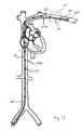
- FIG. 1is a perspective illustration depicting human cardiac anatomy.
- FIG. 2is a cross-sectional plan view of an implantable intravascular pacing device according to one embodiment of the present invention.
- FIG. 2Ais a schematic representation of FIG. 2 .
- FIG. 3is a cross-sectional plan view of an implantable intravascular pacing device according to another embodiment of the present invention.
- FIG. 3Ais a schematic representation of FIG. 3 .
- FIG. 4is a cross-sectional plan view of an implantable intravascular pacing device according to another embodiment of the present invention.
- FIG. 5is a cross-sectional plan view of an implantable intravascular pacing device according to another embodiment of the present invention.
- FIG. 5Ais a schematic representation of FIG. 5 .
- FIG. 6is a cross-sectional plan view of an implantable intravascular defibrillation device according to one embodiment of the present invention.
- FIG. 6Ais a schematic representation of FIG. 6 .
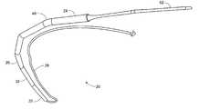
- FIG. 7is a perspective view an implantable intravascular defibrillation device according to one embodiment of the present invention.
- FIG. 8is a perspective view of an anchoring arrangement according to a further embodiment of the present invention.
- FIG. 9is an exploded view of the anchoring arrangement of FIG. 8 .
- FIG. 10is a perspective view of an anchor and cleat according to one embodiment of the present invention.
- FIG. 10Ais a closeup detail view of FIG. 10 , depicting the connection between the cleat and the anchor.
- FIG. 10Bis a side plan view of FIG. 10 .
- FIG. 10Cis a top plan view of FIG. 10 .
- FIG. 11is a cutaway view of one embodiment of an anchor arrangement implanted within a vessel.
- FIG. 12is a cutaway view of a further embodiment of an anchor arrangement implanted within a vessel.
- FIG. 13is a perspective view depicting an anchor arrangement according to the present invention.
- FIG. 14is a close-up perspective view of FIG. 13 .
- FIG. 15is a perspective view of one embodiment of the present invention.
- FIG. 16is a perspective view depicting a further anchor arrangement according to the present invention.
- FIG. 1the general cardiac anatomy of a human is depicted, including the heart and major vessels.
- the following anatomic locationsare shown and identified by the listed reference numerals: Right Subclavian 102 a , Left Subclavian 102 b , Superior Vena Cava (SVC) 103 a , Inferior Vena Cava (IVC) 103 b , Right Atrium (RA) 104 a , Left Atrium (LA) 104 b , Right Innominate/Brachiocephalic Vein 105 a , Left Innominate/Brachiocephalic Vein 105 b , Right Internal Jugular Vein 106 a , Left Internal Jugular Vein 106 b , Right Ventricle (RV) 107 a , Left Ventricle (LV) 107 b , Aortic Arch 108 , Descending Aorta 109 , Right Cephalic Vein 109 a (not shown in FIG. 1 ), Left
- intravascular electrophysiological systemsthat may be used for a variety of functions to treat cardiac arrhythmias with electrical stimulation. These functions include defibrillation, pacing, and/or cardioversion.
- the elements of an intravascular implantable device for electrophysiological therapyinclude at least one device body and typically, but optionally, at least one lead coupled to the body. While the present invention is directed to anchoring and retention of the device body of an intravascular implantable device, it will be understood that, in some embodiments, the one or more leads may also be anchored or retained in the vasculature or within the heart. Alternatively, the intravascular implantable device may have no leads, such as for an embodiment of an intravascular implantable drug/gene therapy device, or the one or more leads may not be anchored or retained in the vasculature or within the heart.
- intravascular implantable electrophysiology devicessuch as intravascular defibrillation and/or pacing devices 20 and leads 28 will be given in this description.
- reference numeralssuch as 20 a , 20 b , 20 c , etc., will be used to describe certain embodiments of the intravascular device 20
- reference numeral 20may be used to more generally refer to intravascular devices of the type that may be used with the present invention for providing therapy other than, or in addition to, cardiac electrophysiology.
- reference number 28may be used generally to refer to leads of a type that may be used with the system.
- Reference number 100refers generally to vessels and/or vessel walls within the human body.
- device 20includes components, known in the art to be necessary to carry out the system functions of an implantable electrophysiology device.
- device 20may include one or more pulse generators, including associated batteries, capacitors, microprocessors, communication circuitry and circuitry for generating electrophysiological pulses for defibrillation, cardioversion and/or pacing.
- Device 20may also include detection circuitry for detecting arrhythmias or other abnormal activity of the heart. The specific components to be provided in device 20 will depend upon the application for the device, and specifically whether device 20 is intended to perform defibrillation, cardioversion, and/or pacing along with sensing functions.
- Device 20can be proportioned to be passed into the vasculature and to be anchored within the vasculature of the patient with minimal obstruction to blood flow.
- Suitable sites for introduction of device 20 into the bodycan include, but are not limited to, the venous system using access through the right or left femoral vein or the right or left subclavian vein.
- the various portions of the device 20will be referenced to the location of those portions, the proximal portion 22 , the distal portion 24 and the middle portion 26 relative to the introduction site in the femoral vein.
- Device 20generally includes a proximal end and a distal end.
- distal portion 24may be defined as being part of the device body, encompassing up to the distal-most third of the body of device 20 .
- distal portion 24may be defined as encompassing part of the body of device 20 and part of tether portion 52 .
- distal portion 24is defined as not encompassing the device body at all, rather it encompasses tether portion 52 .
- the device 20can have a streamlined maximum cross sectional diameter which can be in the range of 3-15 mm or less, with a maximum cross-sectional diameter of 3-8 mm or less in one embodiment.
- the cross-sectional area of device 20 in the transverse directioncan preferably be as small as possible while still accommodating the required components. This area can be in the range of approximately 79 mm2 or less, in the range of approximately 40 mm2 or less, or between 12.5-40 mm2, depending upon the embodiment and/or application.
- the cross-section of device 20may have a circular cross-section, although other cross-sections including crescent, flattened, or elliptical cross-sections may also be used. It can be highly desirable to provide the device with a smooth continuous contour so as to avoid voids or recesses that could encourage thrombus formation on the device. It can also be desirable to provide for a circular cross-section to aid in removal or explantation of the device that more easily permits the device to be torqued or rotated during the removal or explantation to break free of any thrombosis or clotting that may have occurred.
- the cross-section of device 20is generally isodiametric along the entirety of its longitudinal length other than for tapered portions at the proximal and distal ends of the device 20 .
- the aspect ratio of the cross-section of the device 20 to a longitudinal length of the body portion of the device 20is less than 1:10 (e.g., 10 mm diameter to 10 cm length) and in another embodiment is less than 1:50.
- the housing of device 20may be covered by an electrically insulative layer or coating such as ePTFE. It may be desirable to provide a coating that is anti-thrombogenic (e.g., perfluorocarbon coatings applied using supercritical carbon dioxide) so as to prevent thrombus formation on device 20 . It may also be beneficial that the coating have anti-proliferative properties so as to minimize endothelialization or cellular in growth, since minimizing growth into or onto device 20 will help minimize vascular trauma when the device is explanted. The coating may thus also be one which elutes anti-thrombogenic compositions (e.g., heparin sulfate) and/or compositions that inhibit cellular in growth and/or immunosuppressive agents. If the housing of device 20 is conductive, this layer or coating may be selectively applied or removed to leave an exposed electrode region on the surface of the housing where necessary, such as depicted in FIGS. 2-6A .
- this layer or coatingmay be selectively applied or removed to leave an exposed electrode region
- one or more leads 28may extend from device 20 proximate any of the various portions 22 , 24 and 26 of the device 20 .
- a single lead 28is shown, extending from the proximal end 22 of device 20 .
- a lead 28includes one or more electrodes, such as tip electrodes, ring electrodes, or defibrillation electrodes.
- a lead 28may be included within tether portion 52 . If two leads 28 are used, they may extend from opposite ends of device 20 , or they may extend from the same end of the device 20 , such as depicted in FIGS. 4-5 .
- Either or both of the leadsmay be equipped to sense electrical activity of the heart. Monitoring of the heart's electrical activity is needed to detect the onset of an arrhythmia. Activity sensed by the sensing electrode(s) is used by device 20 electronics to trigger delivery of a defibrillation shock that in one embodiment may be delivered via lead 28 having a defibrillation electrode or delivery of a pacing impulse that in one embodiment may be delivered via lead 28 via a pacing electrode.
- the lead 28may be a conventional defibrillation/pacing lead, although alternative lead configurations may be desirable if warranted by the desired placement of the device 20 and lead within the body.
- An optimal leadwill preferably give the physician implanting the device flexibility to position the device at an appropriate location in the chosen vessel without concern that the leads extending from the device will not reach their intended location.
- the leadmay include a coiled section that is similar to the configuration of a coiled telephone cord. A coiled section can allow elongation of the effective length of the lead when tension is applied to the coil.
- the coiled section or any alternate type of yieldable lead sectionmay be a plastically deformable metal or polymer that will retain its extended configuration after it has been stretched to that configuration. Other configurations that will allow additional lead length to pull out from the device if needed may also be used.
- the leadmay include a helical screw-in tip or be of the tined variety for fixation to the cardiac tissue.
- a detachable screw-in lead tipmay be provided, which allows the lead tip to be left within the chamber of the heart when lead 28 is extracted.
- Lead 28may have a steroid-eluding tip to facilitate tissue in-growth for fixation purposes, or may include non-thrombogenic and/or non-proliferative surfaces or coatings similar to those as may be applied to device 20 .
- lead 28may include a coating that is anti-thrombogenic (e.g. perfluorocarbon coatings applied using supercritical carbon dioxide) so as to prevent thrombus formation on the lead. It is also beneficial for the coating to have anti-proliferative properties so as to minimize endothelialization or cellular ingrowth, since minimizing growth into or onto the lead will help minimize vascular trauma when the device is explanted.
- the coatingmay thus also be one which elutes anti-thrombogenic compositions (e.g. heparin sulfate) and/or compositions that inhibit cellular in-growth and/or immunosuppressive agents.
- the term “lead”is used to mean an element that includes conductors and electrodes in an elongated, sealed and insulated protective configuration that is adapted to withstand chronic implantation and is generally floppy in flexibility to permit the electrodes to be positioned somewhat remotely from the circuitry that energizes the electrodes via the conductors.
- the lead 28may be integrated with the device body, or attachable to the device body in situ or prior to implantation, or the lead 28 may be integral with the device body as an extension of the device itself.
- leadsmay include elements that are simply extensions or tapers of the device 12 a itself (such as the portion of the device 12 a at which electrodes 22 a are located) as well as more conventional leads.
- More than one lead 28may be provided, and leads may be included on the proximal/inferior end of the device body, on the distal/superior portion of the device body, generally on the device body, and/or any combination thereof.
- an end of the device bodymay be modified to include a stepped portion proximate the lead connection, such as on the proximal end of the device. The stepped portion allows a smooth transition between the exterior surface of the lead and the device body.
- FIGS. 2-6AExamples of devices having space efficient arrangements of their contents are shown in FIGS. 2-6A .
- One exampleis identified by reference numeral 20 a in FIG. 2 .
- One embodiment of device 20 aincludes one or more elongate housings or enclosures 32 depicted in cross-section in FIG. 2A to allow the components housed within it to be seen.
- enclosure 32is a rigid or semi-rigid housing preferably formed of a material that is conductive, biocompatible, capable of sterilization and capable of hermetically sealing the components contained within the enclosure 32 .
- a materialis titanium, although other materials may also be used.
- components 34 aare associated with delivery of a defibrillation pulse via a lead 28 ( FIG. 6 ), whereas components 34 b are associated with the sensing function performed using sensing electrodes on the defibrillation lead, on a separate lead 28 (e.g., FIGS. 4 and 5 ), or on the device body itself. Isolating components 34 a from components 34 b may be desirable if noise generated by the high voltage defibrillation circuitry 34 a during charging might interfere with performance of the sensing circuitry 34 b , or if practical limitations exist with respect to circuit interconnects 42 .
- Device 20 afurther includes one or more batteries 36 for supplying power to the device, and in some embodiments, and/or one or more exposed body electrodes 40 on an exterior surface of enclosure 32 .
- One or more circuit interconnects 42can provide the electrical coupling between the electronic components 34 , one or more leads 28 , electrode(s) 40 , and batteries 36 . Additional circuitry may be provided to facilitate recharging batteries 36 .
- a second example of an arrangement of components for the intravascular implantable pacing deviceis identified by reference numeral 20 b and shown in FIGS. 3-3A .
- the components of device 20 bmay be arranged in series with one another to give device 20 b a streamlined profile. Because device 20 b is intended for implantation within the patient's vasculature, some flexibility is desired so as to allow the elongate device to be easily passed through the vasculature.
- Flexibilitymay be added by segmenting device 20 b , such as by forming one or more breaks in the enclosure, and by forming one or more hinge zones or bellows at each break which form dynamic flexible zones that can bend relative to the longitudinal axis of the device 20 b in response to passage and/or positioning of device 20 b though curved regions of the vasculature.
- each segmentmay be separately enclosed by its own titanium (or similar) enclosure in the form of containers or compartments 32 .
- the components within the containers 32may be electrically connected by flexible circuit connects 42 , for example.
- the containers 32are connected using a flexible material such as silicone rubber filler to form hinge zones.
- flexible device 20includes one or more rigid enclosures or containers 32 used to contain electronic components 34 to be implanted inside the vasculature of a patient and having the hinge zones formed of a bellows arrangement 48 .
- Containers 32can be of any appropriate shape, cross-section, and length, but in this example are shown to have a cylindrical shape with a diameter of approximately 3-15 mm and a length of approximately 20 mm to 75 mm.
- Containers 32can be used to house electromechanical parts or assemblies to form sophisticated implantable devices such as defibrillators, pacemakers, and drug delivery systems. Any appropriate number of these containers 32 can be combined using interconnecting bellows 48 .
- Interconnecting mechanical bellows 48can be used, to connect a number of rigid containers 32 in order to form a flexible device 20 . For many devices, this will include a string of at least three containers 32 .
- the aspect ratio of the cross-sectional diameter to the longitudinal length of each containeris less than at least 1.5:2 (e.g., 15 mm diameter to 20 mm length) and in another embodiment the aspect ratio is at least 1:4.
- the bellows 48can be of any appropriate shape, but can preferably have a shape similar in cross-section to the cross-section of the container, in order to prevent the occurrence of edges or ridges that can give rise to problems such as the formation of blood clots in the vasculature.
- the bellowscan be made of a biocompatible material similar to the containers. Any coatings used for electrically insulating the containers and/or making the containers more hemo-dynamically compatible also can be used with the bellows.
- the bellows 48In addition to the ability of the bellows 48 to bend away from the central or long axis of device 20 , the bellows 48 also allow for flexibility along the central axis of the device.
- the ability to flex along the central axisprovides shock absorption in the long axis as well as 3-dimensional flexing. Shock absorption can help to protect device 20 and internal components during the implant process by minimizing the motion of the implanted device. Further, shock absorption can provide a 1:1 torque ratio for steering during the implant process.
- the shock absorptionalso can help during the life of device 20 , as the natural movement of the body of a patient can induce some stress on the device 20 .
- FIGS. 4-5Aanother embodiment of the device, identified by reference numeral 20 c , is depicted.
- Device 20 cis similar to the embodiment depicted in FIGS. 3-3A , however device 20 c includes multiple leads 28 on the proximal portion 22 of device 20 c.
- Device 20 dis an intravascular implantable defibrillation device, having a lead 28 adapted to inserted into the right ventricle of a patient.
- Device 20 dfurther includes one or more sensing electrodes, which may be located on the exterior of enclosure 32 , similar to body electrodes 40 .
- Device 20 dalso includes one or more defibrillation electrodes on the exterior of enclosure 32 .
- the deviceis preferably able to communicate via wireless telemetry to an instrument outside of the patient's body.
- Thisis commonly referred to as device interrogation and/or programming and allows the physician to monitor the state and performance of the device. It also allows the physician to reconfigure the device in the case of programmable settings.
- the circuitry used for device interrogation and/or programmingcan be included in all of device 20 embodiments, with the device telemetry antenna either encapsulated within the device enclosure or as part of the tether potion 52 discussed in more detail below.
- the circuitrymay include a circuit that will respond in the presence of a magnetic field, electric field, a near-field or a far-field, all which are features also known in the implantable device industry.
- the status informationmay include the state of the battery system, and whether or not a therapeutic energy delivery had occurred or not.
- the communicationmight also identify the parameters device 20 used, including stored electrograms, to allow reconstruction of the delivery episode by the instrument.
- the telemetry featuremay also be used to program certain features governing function of device 20 , such as the threshold heart rate in beats per minute which, when detected by the device, will cause the device to provide appropriate energy therapy.
- distal portion 24 of device 20includes a tether portion 52 .
- device 20is routed through the inferior vena cava 103 b , through superior vena cava 103 a , and then on to one of a number of locations superior to the superior vena cava 103 a as will be described.
- Device 20is then anchored within the vasculature using an anchor 50 .
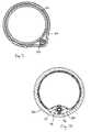
- Anchor 50is configured to retain device 20 within a patient's vasculature, and in one embodiment anchor 50 comprises a conventional intravascular stent.
- the anchor 50may include features that give some structural stability to cause the anchor to radially support device 20 against a vessel wall 100 .
- a mesh or other framework formed of shape memory (e.g., nickel titanium alloy, nitinol or shape memory polymer) elements or stainless steel wiresmay be used to form anchor 50 .
- the anchor 50is provided with a smooth polymeric barrier that is both anti-proliferative and anti-thrombogenic and that thereby prevents endothelial growth and thrombus formation on the anchor.
- polymeric barrierexamples include, but are not limited to ePTFE, or other fluoropolymers, silicone, non-woven nylon, or biomimetic materials.
- the polymeric barrieris preferably formed by layers of barrier material on the interior and exterior surfaces of the framework, although it will be appreciated that the framework and barrier may be combined in a variety of ways to prevent thrombus formation and endothelialization on the anchor walls.
- the anchor materialcould include surfaces for eluting non-coagulative, anti-platelet (e.g. IIBIIIA glycoprotein receptor blockers), anti-proliferative, and/or anti-inflammatory substances.
- the anchorrelies solely on a non-biological fixation to secure the anchor within the vessel, such as mechanical fixation by the radial expansion force of an anchor 50 or hooking, latching, catching or cleating the anchor 50 with respect to the vessel.
- the mechanical fixationmay be augmented with by a glue or other non-biological adhesive interfaced between the anchor and the vessel which for purposes of the present invention would be considered part of a non-biological, as opposed to biological, fixation of the anchor.
- the fixation of the anchormay be accomplished solely by a glue or other non-biological adhesive interfaced between the anchor and vessel.
- the anchormay eventually rely on biological fixation such as from endothelialization or thrombus formation to assist in retaining the anchor within the vessel in addition to the initial non-biological fixation at the time of implantation.
- device 20may generally be anchored by active or passive means.
- tether portion 52may be secured by being “sandwiched” between a vessel wall 100 and anchor 50 , as depicted in FIG. 11 .
- tether portion 52may be secured by a mechanical coupling with anchor 50 , such as depicted in FIGS. 8 and 12 .
- Anchor 50may be separate from tether portion 52 , although in one embodiment anchor 50 may also be integrated with tether portion 52 . In an alternate embodiment, anchor 50 , either integrated or separable, may be used to secure the body of the device 20 at the distal portion 24 , where the body does not include a unique tether portion 52 . In one embodiment, the tether portion 52 is selectively detachable from the body of the device 20 to facilitate extraction and/or explantation of the device 20 . Device 20 is preferably able to communicate via wireless telemetry to an instrument outside of the patient's body and in one embodiment, tether portion 52 may include an internal antenna to facilitate device interrogation and/or programming. In another embodiment, the internal antenna is not within detachable portion 52 . For more details of the various embodiments of the tether portion 52 , reference is made to Provisional Application No. 60/868,434, filed Dec. 4, 2006, the disclosure of which has been incorporated by reference herein.
- tether portion 52is preferably of a smaller diameter than device 20 . Minimizing the diameter of tether portion 52 is desirable so as to reduce bulging and/or irritation of the vessel 100 .
- tether portion 52is sufficiently flexible to allow bending during implantation, yet is more rigid than the floppy flexibility of leads 28 .
- tether portion 52includes a retention tip 60 , which is configured to prevent tether portion 52 from being pulled out from anchor 50 . Tip 60 functions as a stop, interfering with the distal end of anchor 50 and preventing tether 52 from being pulled out from between anchor 50 and vessel wall 100 .
- tether portion 52may include an electrode for defibrillation, pacing, or sensing of cardiac electrical activity.
- the use of an electrode positioned in tether portion 52may be especially useful for defibrillation to generate a shock vector across the heart.
- Tether 52is coupleable to a device 20 , and may include a passage suitable for insertion of a guidewire to assist in implantation. As with other embodiment, tether 52 may also include an antenna for communication purposes.
- a cleat 90is depicted, being configured to couple to tether 52 and an anchor 50 .
- Cleat 90includes one or more features for coupling to anchor 50 , such as clips 92 which are configured to interact with the mesh features of anchor 50 .
- One or more fins 93are disposed on the cleat body.
- a platform area 94may be provided on cleat 90 , the platform providing a suitable surface for deploying a self-expanding anchor therefrom during implantation.
- Cleat 96also may include a connection point for coupling to tether 52 , and includes one or more attachment features 96 .
- Cleat 90may be configured to be removably coupled to tether 52 , or integrated therewith, or may be molded to tether 52 , or other connection arrangements as will be appreciated by one skilled in the art.
- cleat 90is configured to correctly orient the cleat during implantation such that engagement of anchor 50 is easy to achieve.
- the placement of clips 92 and fins 93act together, such that when cleat 90 is in a target vessel, any rotational orientation of the cleat will result in one of clips 92 being able to be engaged with anchor 50 .
- cleat 90may be adapted to couple to a strut 51 of stent 50 .
- device 20is implanted by making an incision in the patient's femoral vein, and inserting an introducer sheath through the incision into the vein.
- the introducer sheathkeeps the incision open during the procedure, and includes a seal adapted to prevent blood from exiting the body while allowing the insertion of various tools and devices into the body.
- Device 20may be introduced in a number of ways.
- the device 20may be introduced by an over-the-wire technique.
- the distal end or distal portion of device 20is provided with a passageway configured to receive a guidewire, and the device is slid onto the guide wire, then the distal end of device 20 is introduced through the seal.
- Device 20is guided through the vasculature of the patient, into the inferior vena cava, then the superior vena cava, and into the subclavian vein or other vessel superior to the heart.
- a device delivery cathetermay be used to facilitate introducing the device.
- Anchor 50is introduced.
- Anchor 50may be inserted through the seal in the femoral incision used to implant device 20 .
- anchor 50is inserted from another incision such as through an incision closer to the location of tether portion 52 .
- anchor 50may be introduced after device 20 has been positioned at the desired location within the vessel. In another embodiment, anchor 50 may be introduced prior to device 20 being introduced.
- anchor 50may be delivered over the guide wire, such as with an anchor delivery catheter.
- Anchor 50compressed to a streamlined position, is passed through the vasculature and approaches the distal portion of the device where the anchor will interfere with where the wire enters the tip of the device.
- the guide wiremust be removed from the device and guided around the tip of the device to provide a path for the anchor.
- the anchoris then guided around the device and past the distal-most portion of the device tip.
- Anchor 50may be self-expanding and/or it may be expanded using an inflation tool such as a balloon passed into the anchor's central lumen and subsequently inflated.
- anchor 50When anchor 50 is expanded, its radial forces engage tether portion 52 and secure tether portion 52 against vessel wall 100 , as depicted in FIG. 11 .
- the expansion force of the anchor against tether portion 52may cause the vessel wall 100 to bulge outwardly.
- the anchor 50may deform around the shape of tether portion 52 , leaving vessel 100 at its normal shape.
- both anchor 50 and vessel 100deform to accommodate tether portion 52 . It is desirable to minimize the diameter of tether portion 52 , to minimize deformation of anchor 50 and/or vessel 100 .
- anchor 50 in its compressed stateis guided proximate platform 94 of cleat 90 .
- a sheath holding the anchor compressedis released, allowing the anchor to radially expand into the vessel.
- Cleat 90coupled to device 20 via tether 52 , is sandwiched between deployed anchor 50 and vessel wall 100 .
- device 20is manipulated, such as by its proximal end, so that cleat 90 is pulled into anchor 50 .
- Clip 92is then secured onto the mesh of anchor 50 , such as depicted in FIGS. 8 , 10 and 10 A.
- Device 20is then secured in the vasculature.
- a cutaway view of cleat 90 secured to anchor 50 in a vessel 100is depicted in FIG. 12 .
- the leadis then delivered and implanted according to the desired application of device 20 . Additional details pertaining to the lead can be found in U.S. Provisional Application titled “Implantation Methods, Systems and Tools for Intravascular Implantable Devices”, filed Dec. 3, 2007, the disclosure of which has been incorporated by reference herein.
- suitable locations for anchoring device 20are referred to as superior (i.e., generally above the heart in a direction toward the head) for purposes of describing the various embodiments of the present invention in that these locations are superior of the heart and in some embodiments superior of the superior vena cava 103 a .
- a suitable superior anchoring location proximate a distal portion of the device 20effectively permits the remainder of device 20 to float, rather than lay, within the vasculature.
- suitable superior locations for anchoring the distal portion of device 20include the right or left innominate (brachiocephalic) veins 105 a or 105 b , the right or left subclavian veins 102 a or 102 b , the right or left cephalic veins 109 a or 109 b.
- these superior anchoring locationssuch as the right or left innominate (brachiocephalic) veins 105 a or 105 b , the right or left subclavian veins 102 a or 102 b , the right or left cephalic veins 109 a or 109 b , are veins within the torso where alternative venous drain routes will exist in the event of fibrosis and/or stenosis proximate the anchoring location. Suitable superior anchoring locations further tend to provide for easier bailout in the event of a problem with device 20 requiring explantation by virtue of easier surgical accessibility.
- all of these locationscreate an effective anchoring location that is generally oriented transverse to the general direction (in a standing human patient) of gravitational force or drop force on the portion of the device 20 that may reside within the vena cava.
- the generally transverse orientation to the direction of gravitational or drop force afforded by these locationsaids in dissipating these forces without dislodging the anchor 50 .
- the distal portion of device 20potentially could be anchored in the left internal jugular vein 106 b or the right internal jugular vein 106 a
- these veinsare less medically desirable locations because the veins are located generally outside the torso and in the neck and therefore will have more potential complications in the event of fibrosis and/or stenosis proximate the anchoring location.
- the right internal jugular vein 106 ais also a less desirable anchoring location due to the challenges associated with drop tests. Similar to the problems associated with anchoring the device lower in the torso, anchoring the present invention in the right internal jugular vein 106 a may not adequately secure the implantable device during drop tests that simulate the effect of a patient falling or jumping.
- a first suitable superior anchor locationis proximate the subclavian crush zone 111 , which is defined as the region of the right subclavian vein 102 a or left subclavian vein 102 b that can be compressed between a patient's clavicle and first rib due to upward movement of the patient's arm.
- the objectcan become damaged, potentially leading to failure of the object or damage to the vessel.
- device 20is positioned proximate subclavian crush zone 111 , while tether portion 52 extends across and through the crush zone, and is secured with an anchor 50 located beyond and peripheral of subclavian crush zone 111 , as depicted in FIGS. 13-15 .
- a second suitable superior anchor locationis within the right 105 a or left 105 b cephalic veins, as depicted in FIG. 16 .
- device 20is generally positioned proximate subclavian crush zone 111 , while tether portion 52 extends across and through the crush zone, and into the cephalic vein. Tether portion 52 is secured with an anchor 50 in the cephalic vein.
- Such implantsmight include, for example, implantable neurostimulators, artificial pancreas implants, diagnostic implants with sensors that gather data such as properties of the patient's blood (e.g. blood glucose level) and/or devices that deliver drugs or other therapies into the blood from within a blood vessel.
- implantable neurostimulatorse.g., artificial pancreas implants
- diagnostic implantswith sensors that gather data such as properties of the patient's blood (e.g. blood glucose level) and/or devices that deliver drugs or other therapies into the blood from within a blood vessel.
Landscapes
- Health & Medical Sciences (AREA)
- Heart & Thoracic Surgery (AREA)
- Engineering & Computer Science (AREA)
- Biomedical Technology (AREA)
- Cardiology (AREA)
- Veterinary Medicine (AREA)
- Vascular Medicine (AREA)
- Life Sciences & Earth Sciences (AREA)
- Animal Behavior & Ethology (AREA)
- General Health & Medical Sciences (AREA)
- Public Health (AREA)
- Transplantation (AREA)
- Oral & Maxillofacial Surgery (AREA)
- Nuclear Medicine, Radiotherapy & Molecular Imaging (AREA)
- Radiology & Medical Imaging (AREA)
- Electrotherapy Devices (AREA)
Abstract
Description
Claims (12)
Priority Applications (2)
| Application Number | Priority Date | Filing Date | Title |
|---|---|---|---|
| US11/999,519US8311633B2 (en) | 2006-12-04 | 2007-12-04 | Intravascular implantable device having superior anchoring arrangement |
| US12/957,969US20110071585A1 (en) | 2006-12-04 | 2010-12-01 | Intravascular implantable device having superior anchoring arrangement |
Applications Claiming Priority (3)
| Application Number | Priority Date | Filing Date | Title |
|---|---|---|---|
| US86843406P | 2006-12-04 | 2006-12-04 | |
| US86843706P | 2006-12-04 | 2006-12-04 | |
| US11/999,519US8311633B2 (en) | 2006-12-04 | 2007-12-04 | Intravascular implantable device having superior anchoring arrangement |
Related Child Applications (1)
| Application Number | Title | Priority Date | Filing Date |
|---|---|---|---|
| US12/957,969ContinuationUS20110071585A1 (en) | 2006-12-04 | 2010-12-01 | Intravascular implantable device having superior anchoring arrangement |
Publications (2)
| Publication Number | Publication Date |
|---|---|
| US20080167702A1 US20080167702A1 (en) | 2008-07-10 |
| US8311633B2true US8311633B2 (en) | 2012-11-13 |
Family
ID=39594959
Family Applications (2)
| Application Number | Title | Priority Date | Filing Date |
|---|---|---|---|
| US11/999,519Expired - Fee RelatedUS8311633B2 (en) | 2006-12-04 | 2007-12-04 | Intravascular implantable device having superior anchoring arrangement |
| US12/957,969AbandonedUS20110071585A1 (en) | 2006-12-04 | 2010-12-01 | Intravascular implantable device having superior anchoring arrangement |
Family Applications After (1)
| Application Number | Title | Priority Date | Filing Date |
|---|---|---|---|
| US12/957,969AbandonedUS20110071585A1 (en) | 2006-12-04 | 2010-12-01 | Intravascular implantable device having superior anchoring arrangement |
Country Status (1)
| Country | Link |
|---|---|
| US (2) | US8311633B2 (en) |
Cited By (28)
| Publication number | Priority date | Publication date | Assignee | Title |
|---|---|---|---|---|
| US20160008612A1 (en)* | 2014-06-25 | 2016-01-14 | Sorin Crm Sas | Hybrid system forming an active implantable medical device |
| US20160271404A1 (en)* | 2015-03-18 | 2016-09-22 | Sorin Crm Sas | Active implantable medical device comprising a connector-free capsule, permanently connected to a microlead |
| US9814889B2 (en) | 2012-11-21 | 2017-11-14 | Newpace Ltd. | Injectable subcutaneous string heart device |
| US9878150B2 (en) | 2005-09-12 | 2018-01-30 | The Cleveland Clinic Foundation | Methods and systems for increasing heart contractility by neuromodulation |
| US10172549B2 (en) | 2016-03-09 | 2019-01-08 | CARDIONOMIC, Inc. | Methods of facilitating positioning of electrodes |
| US20190126051A1 (en)* | 2016-05-03 | 2019-05-02 | Newpace Ltd. | Flexible semi-hermetic implantable medical device structure |
| US10307273B2 (en) | 2015-03-03 | 2019-06-04 | Boston Scientific Scimed, Inc. | Stent with anti-migration features |
| US10398901B2 (en) | 2015-02-06 | 2019-09-03 | Cardiac Pacemakers, Inc. | Systems and methods for treating cardiac arrhythmias |
| US10434316B2 (en) | 2014-09-08 | 2019-10-08 | Newpace Ltd. | Flexible rechargeable implantable subcutaneous medical device structure and method of assembly |
| US10493278B2 (en) | 2015-01-05 | 2019-12-03 | CARDIONOMIC, Inc. | Cardiac modulation facilitation methods and systems |
| US10576273B2 (en) | 2014-05-22 | 2020-03-03 | CARDIONOMIC, Inc. | Catheter and catheter system for electrical neuromodulation |
| US10716944B2 (en) | 2017-03-20 | 2020-07-21 | Cardiac Pacemakers, Inc. | Systems and methods for treating cardiac arrhythmias |
| US10722716B2 (en) | 2014-09-08 | 2020-07-28 | Cardionomia Inc. | Methods for electrical neuromodulation of the heart |
| US10894160B2 (en) | 2014-09-08 | 2021-01-19 | CARDIONOMIC, Inc. | Catheter and electrode systems for electrical neuromodulation |
| US10894167B2 (en) | 2017-12-22 | 2021-01-19 | Cardiac Pacemakers, Inc. | Implantable medical device for vascular deployment |
| US10898675B2 (en) | 2015-06-15 | 2021-01-26 | Hollister Incorporated | Urinary catheters having limited reusability |
| US10994148B2 (en) | 2017-03-20 | 2021-05-04 | Cardiac Pacemakers, Inc. | Systems and methods for treating cardiac arrhythmias |
| US11000690B2 (en) | 2017-03-20 | 2021-05-11 | Cardiac Pacemakers, Inc. | Systems and methods for treating cardiac arrhythmias |
| US11077299B2 (en)* | 2017-03-07 | 2021-08-03 | Cardiac Pacemakers, Inc. | Implantation of an active medical device |
| US11077298B2 (en) | 2018-08-13 | 2021-08-03 | CARDIONOMIC, Inc. | Partially woven expandable members |
| US11123570B2 (en) | 2017-12-22 | 2021-09-21 | Cardiac Pacemakers, Inc. | Implantable medical device for vascular deployment |
| US11160989B2 (en) | 2017-03-20 | 2021-11-02 | Cardiac Pacemakers, Inc. | Systems and methods for treating cardiac arrhythmias |
| US11446510B2 (en) | 2019-03-29 | 2022-09-20 | Cardiac Pacemakers, Inc. | Systems and methods for treating cardiac arrhythmias |
| US11510697B2 (en) | 2019-09-11 | 2022-11-29 | Cardiac Pacemakers, Inc. | Tools and systems for implanting and/or retrieving a leadless cardiac pacing device with helix fixation |
| US11559687B2 (en) | 2017-09-13 | 2023-01-24 | CARDIONOMIC, Inc. | Methods for detecting catheter movement |
| US11571582B2 (en) | 2019-09-11 | 2023-02-07 | Cardiac Pacemakers, Inc. | Tools and systems for implanting and/or retrieving a leadless cardiac pacing device with helix fixation |
| US11607176B2 (en) | 2019-05-06 | 2023-03-21 | CARDIONOMIC, Inc. | Systems and methods for denoising physiological signals during electrical neuromodulation |
| US11833349B2 (en) | 2019-03-29 | 2023-12-05 | Cardiac Pacemakers, Inc. | Systems and methods for treating cardiac arrhythmias |
Families Citing this family (40)
| Publication number | Priority date | Publication date | Assignee | Title |
|---|---|---|---|---|
| CA2508800A1 (en) | 2002-12-11 | 2004-06-24 | Proteus Biomedical, Inc. | Method and system for monitoring and treating hemodynamic parameters |
| EP1871470A4 (en) | 2005-03-31 | 2011-06-01 | Proteus Biomedical Inc | Automated optimization of multi-electrode pacing for cardiac resynchronization |
| US7684864B2 (en)* | 2005-04-28 | 2010-03-23 | Medtronic, Inc. | Subcutaneous cardioverter-defibrillator |
| WO2007021804A2 (en) | 2005-08-12 | 2007-02-22 | Proteus Biomedical, Inc. | Evaluation of depolarization wave conduction velocity |
| US8311633B2 (en)* | 2006-12-04 | 2012-11-13 | Synecor Llc | Intravascular implantable device having superior anchoring arrangement |
| US7917230B2 (en) | 2007-01-30 | 2011-03-29 | Cardiac Pacemakers, Inc. | Neurostimulating lead having a stent-like anchor |
| US20080183187A1 (en) | 2007-01-30 | 2008-07-31 | Cardiac Pacemakers, Inc. | Direct delivery system for transvascular lead |
| WO2009073754A2 (en) | 2007-12-03 | 2009-06-11 | Innerpulse | Implantation methods, systems and tools for intravascular implantable devices |
| US8473069B2 (en) | 2008-02-28 | 2013-06-25 | Proteus Digital Health, Inc. | Integrated circuit implementation and fault control system, device, and method |
| US8593107B2 (en)* | 2008-10-27 | 2013-11-26 | Cardiac Pacemakers, Inc. | Methods and systems for recharging an implanted device by delivering a section of a charging device adjacent the implanted device within a body |
| WO2010126503A1 (en)* | 2009-04-29 | 2010-11-04 | Proteus Biomedical, Inc. | Methods and apparatus for leads for implantable devices |
| US8359098B2 (en)* | 2009-05-29 | 2013-01-22 | Medtronic, Inc. | Implantable medical device with exposed generator |
| US9099720B2 (en) | 2009-05-29 | 2015-08-04 | Medtronic, Inc. | Elongate battery for implantable medical device |
| US20100318166A1 (en)* | 2009-06-12 | 2010-12-16 | Terrance Ransbury | Methods and systems for anti-thrombotic intravascular implantable devices |
| WO2011011736A2 (en) | 2009-07-23 | 2011-01-27 | Proteus Biomedical, Inc. | Solid-state thin film capacitor |
| US8718770B2 (en) | 2010-10-21 | 2014-05-06 | Medtronic, Inc. | Capture threshold measurement for selection of pacing vector |
| US8475372B2 (en) | 2010-10-29 | 2013-07-02 | Medtronic Vascular, Inc. | Implantable medical sensor and fixation system |
| US8864676B2 (en) | 2010-10-29 | 2014-10-21 | Medtronic Vascular, Inc. | Implantable medical sensor and fixation system |
| US20120245663A1 (en)* | 2011-03-24 | 2012-09-27 | Zarembo Paul E | Implantable medical device having an adhesive surface portion |
| US8727996B2 (en) | 2011-04-20 | 2014-05-20 | Medtronic Vascular, Inc. | Delivery system for implantable medical device |
| US8355784B2 (en) | 2011-05-13 | 2013-01-15 | Medtronic, Inc. | Dynamic representation of multipolar leads in a programmer interface |
| US9364326B2 (en) | 2011-06-29 | 2016-06-14 | Mitralix Ltd. | Heart valve repair devices and methods |
| US8989873B2 (en) | 2011-07-20 | 2015-03-24 | Medtronic, Inc. | Intravascular medical device with advancable electrode |
| US9351648B2 (en) | 2012-08-24 | 2016-05-31 | Medtronic, Inc. | Implantable medical device electrode assembly |
| EP2732848B1 (en) | 2012-11-14 | 2022-03-02 | Sorin CRM SAS | Microlead for implantation in the deep coronary vessels comprising a deformable proximal part |
| US9168372B2 (en) | 2013-03-07 | 2015-10-27 | Pacesetter, Inc. | Temporary leadless implantable medical device with indwelling retrieval mechanism |
| US10610693B2 (en) | 2013-07-11 | 2020-04-07 | Newpace Ltd. | Battery and electronics integration in a flexible implantable medical device |
| EP3020080B1 (en)* | 2013-07-11 | 2019-08-07 | Newpace Ltd. | Battery and electronics integration in an implantable medical device |
| US9700412B2 (en) | 2014-06-26 | 2017-07-11 | Mitralix Ltd. | Heart valve repair devices for placement in ventricle and delivery systems for implanting heart valve repair devices |
| US10390720B2 (en) | 2014-07-17 | 2019-08-27 | Medtronic, Inc. | Leadless pacing system including sensing extension |
| US9399140B2 (en) | 2014-07-25 | 2016-07-26 | Medtronic, Inc. | Atrial contraction detection by a ventricular leadless pacing device for atrio-synchronous ventricular pacing |
| US9492668B2 (en) | 2014-11-11 | 2016-11-15 | Medtronic, Inc. | Mode switching by a ventricular leadless pacing device |
| US9724519B2 (en) | 2014-11-11 | 2017-08-08 | Medtronic, Inc. | Ventricular leadless pacing device mode switching |
| US9492669B2 (en) | 2014-11-11 | 2016-11-15 | Medtronic, Inc. | Mode switching by a ventricular leadless pacing device |
| US9623234B2 (en) | 2014-11-11 | 2017-04-18 | Medtronic, Inc. | Leadless pacing device implantation |
| US9289612B1 (en) | 2014-12-11 | 2016-03-22 | Medtronic Inc. | Coordination of ventricular pacing in a leadless pacing system |
| WO2016110856A1 (en)* | 2015-01-08 | 2016-07-14 | The Medical Research, Infrastructure and Health Services Fund of the Tel Aviv Medical Center | Cardiac stimulation of atrial-ventricle pathways and/or associated tissue |
| US11207527B2 (en) | 2016-07-06 | 2021-12-28 | Cardiac Pacemakers, Inc. | Method and system for determining an atrial contraction timing fiducial in a leadless cardiac pacemaker system |
| US20200139108A1 (en)* | 2017-05-07 | 2020-05-07 | Newpace Ltd. | Subcutaneous implantable defibrillator with epicardial lead for resynchronization therapy |
| US20210379373A1 (en)* | 2020-06-05 | 2021-12-09 | Medtronic, Inc. | Implantable medical leads and methods for implanting implantable medical leads for sacral modulation therapy |
Citations (51)
| Publication number | Priority date | Publication date | Assignee | Title |
|---|---|---|---|---|
| US3835864A (en) | 1970-09-21 | 1974-09-17 | Rasor Ass Inc | Intra-cardiac stimulator |
| USRE30366E (en) | 1970-09-21 | 1980-08-12 | Rasor Associates, Inc. | Organ stimulator |
| US5170802A (en) | 1991-01-07 | 1992-12-15 | Medtronic, Inc. | Implantable electrode for location within a blood vessel |
| US5405363A (en) | 1991-03-15 | 1995-04-11 | Angelon Corporation | Implantable cardioverter defibrillator having a smaller displacement volume |
| US5487760A (en) | 1994-03-08 | 1996-01-30 | Ats Medical, Inc. | Heart valve prosthesis incorporating electronic sensing, monitoring and/or pacing circuitry |
| US5509411A (en) | 1993-01-29 | 1996-04-23 | Cardima, Inc. | Intravascular sensing device |
| US5531779A (en) | 1992-10-01 | 1996-07-02 | Cardiac Pacemakers, Inc. | Stent-type defibrillation electrode structures |
| US5843132A (en) | 1996-10-07 | 1998-12-01 | Ilvento; Joseph P. | Self-contained, self-powered temporary intravenous pacing catheter assembly |
| US6141588A (en) | 1998-07-24 | 2000-10-31 | Intermedics Inc. | Cardiac simulation system having multiple stimulators for anti-arrhythmia therapy |
| WO2000074557A1 (en) | 1999-06-08 | 2000-12-14 | Schmitz Rode Thomas | Intravascularly implantable device |
| US20010044568A1 (en) | 2000-01-31 | 2001-11-22 | Langberg Jonathan J. | Endoluminal ventricular retention |
| US6360130B1 (en) | 1998-09-30 | 2002-03-19 | Medtronic, Inc. | Temporary bi-polar heart wire |
| US6442413B1 (en) | 2000-05-15 | 2002-08-27 | James H. Silver | Implantable sensor |
| US6445953B1 (en) | 2001-01-16 | 2002-09-03 | Kenergy, Inc. | Wireless cardiac pacing system with vascular electrode-stents |
| US20020143379A1 (en) | 2001-03-27 | 2002-10-03 | Morgan Kevin L. | Electrode assembly with a detachable distal tip |
| US20030109914A1 (en) | 2000-08-30 | 2003-06-12 | Randy Westlund | Coronary vein leads having an atraumatic TIP and method therefor |
| US6613076B1 (en) | 1998-06-04 | 2003-09-02 | Societe De Conseils De Recherches Et D'applications Scientifiques Scras | Implantable intraluminal device |
| US20040116992A1 (en) | 2002-09-26 | 2004-06-17 | Wardle John L. | Cardiovascular anchoring device and method of deploying same |
| US20040138744A1 (en) | 2000-01-31 | 2004-07-15 | Randall Lashinski | Transluminal mitral annuloplasty with active anchoring |
| US20040249431A1 (en)* | 2003-06-04 | 2004-12-09 | Terrance Ransbury | Device and method for retaining a medical device within a vessel |
| US20050016109A1 (en) | 2003-07-21 | 2005-01-27 | Rouse Glenn R. | Radial-hinge mechanism |
| US20050043765A1 (en) | 2003-06-04 | 2005-02-24 | Williams Michael S. | Intravascular electrophysiological system and methods |
| US20050080472A1 (en)* | 2003-10-10 | 2005-04-14 | Atkinson Robert Emmett | Lead stabilization devices and methods |
| US20050154437A1 (en) | 2003-12-12 | 2005-07-14 | Williams Michael S. | Implantable medical device having pre-implant exoskeleton |
| US20050165456A1 (en) | 2003-12-19 | 2005-07-28 | Brian Mann | Digital electrode for cardiac rhythm management |
| US6950705B2 (en) | 2000-09-18 | 2005-09-27 | Cameron Health, Inc. | Canister designs for implantable cardioverter-defibrillators |
| US20050222678A1 (en) | 2004-04-05 | 2005-10-06 | Lashinski Randall T | Remotely adjustable coronary sinus implant |
| US20050228471A1 (en)* | 2003-06-04 | 2005-10-13 | Williams Michael S | Method and apparatus for retaining medical implants within body vessels |
| US20050234431A1 (en)* | 2004-02-10 | 2005-10-20 | Williams Michael S | Intravascular delivery system for therapeutic agents |
| US20050273138A1 (en) | 2003-12-19 | 2005-12-08 | Guided Delivery Systems, Inc. | Devices and methods for anchoring tissue |
| US20060095078A1 (en) | 2004-10-29 | 2006-05-04 | Tronnes Carole A | Expandable fixation mechanism |
| US7072171B1 (en) | 2006-02-13 | 2006-07-04 | Wilson Greatbatch Technologies, Inc. | Electrolytic capacitor capable of insertion into the vasculature of a patient |
| US20060161166A1 (en) | 2001-03-08 | 2006-07-20 | Spine Wave, Inc. | Tissue distraction device |
| US7082336B2 (en) | 2003-06-04 | 2006-07-25 | Synecor, Llc | Implantable intravascular device for defibrillation and/or pacing |
| US20060168791A1 (en) | 1996-05-03 | 2006-08-03 | Jacob Richter | Method of making a bifurcated stent with improved side branch aperture |
| US7101642B2 (en) | 2000-04-26 | 2006-09-05 | Quallion Llc | Rechargeable lithium battery for tolerating discharge to zero volts |
| US20060217779A1 (en) | 2005-03-24 | 2006-09-28 | Terrance Ransbury | Flexible hermetic enclosure for implantable medical devices |
| US7120495B2 (en) | 2000-09-18 | 2006-10-10 | Cameron Health, Inc. | Flexible subcutaneous implantable cardioverter-defibrillator |
| US20070043414A1 (en) | 2005-08-15 | 2007-02-22 | Fifer Daniel W | Lead fixation and extraction |
| US7239921B2 (en) | 2003-06-23 | 2007-07-03 | Alfred E. Mann Foundation For Scientific Research | Housing for an implantable medical device |
| US20070179581A1 (en) | 2006-01-30 | 2007-08-02 | Dennis Charles L | Intravascular medical device |
| US20070179583A1 (en) | 2003-07-25 | 2007-08-02 | Integrated Sensing Systems, Inc. | Delivery system, method, and anchor for medical implant placement |
| US20070179550A1 (en) | 2006-01-30 | 2007-08-02 | Dennis Charles L | Intravascular medical device |
| US20070265673A1 (en) | 2006-04-03 | 2007-11-15 | Terrance Ransbury | Flexible interconnect assembly for implantable medical devices |
| WO2008070120A2 (en) | 2006-12-04 | 2008-06-12 | Innerpulse, Inc. | Intravascular implantable device having superior anchoring arrangement |
| US20080147168A1 (en) | 2006-12-04 | 2008-06-19 | Terrance Ransbury | Intravascular implantable device having detachable tether arrangement |
| US7529586B2 (en) | 2002-12-09 | 2009-05-05 | Medtronic, Inc. | Concavity of an implantable medical device |
| US7627376B2 (en) | 2006-01-30 | 2009-12-01 | Medtronic, Inc. | Intravascular medical device |
| WO2010144916A2 (en) | 2009-06-12 | 2010-12-16 | Innerpulse, Inc. | Methods and systems for anti-thrombotic intravascular implantable devices |
| US20110032387A1 (en) | 2008-04-28 | 2011-02-10 | Panasonic Corporation | Imaging apparatus |
| US20110071585A1 (en)* | 2006-12-04 | 2011-03-24 | Terrance Ransbury | Intravascular implantable device having superior anchoring arrangement |
- 2007
- 2007-12-04USUS11/999,519patent/US8311633B2/ennot_activeExpired - Fee Related
- 2010
- 2010-12-01USUS12/957,969patent/US20110071585A1/ennot_activeAbandoned
Patent Citations (64)
| Publication number | Priority date | Publication date | Assignee | Title |
|---|---|---|---|---|
| US3835864A (en) | 1970-09-21 | 1974-09-17 | Rasor Ass Inc | Intra-cardiac stimulator |
| USRE30366E (en) | 1970-09-21 | 1980-08-12 | Rasor Associates, Inc. | Organ stimulator |
| US5170802A (en) | 1991-01-07 | 1992-12-15 | Medtronic, Inc. | Implantable electrode for location within a blood vessel |
| US5405363A (en) | 1991-03-15 | 1995-04-11 | Angelon Corporation | Implantable cardioverter defibrillator having a smaller displacement volume |
| US5531779A (en) | 1992-10-01 | 1996-07-02 | Cardiac Pacemakers, Inc. | Stent-type defibrillation electrode structures |
| US5509411A (en) | 1993-01-29 | 1996-04-23 | Cardima, Inc. | Intravascular sensing device |
| US6141576A (en) | 1993-01-29 | 2000-10-31 | Cardima, Inc. | Intravascular sensing device |
| US5487760A (en) | 1994-03-08 | 1996-01-30 | Ats Medical, Inc. | Heart valve prosthesis incorporating electronic sensing, monitoring and/or pacing circuitry |
| US20060168791A1 (en) | 1996-05-03 | 2006-08-03 | Jacob Richter | Method of making a bifurcated stent with improved side branch aperture |
| US5843132A (en) | 1996-10-07 | 1998-12-01 | Ilvento; Joseph P. | Self-contained, self-powered temporary intravenous pacing catheter assembly |
| US6613076B1 (en) | 1998-06-04 | 2003-09-02 | Societe De Conseils De Recherches Et D'applications Scientifiques Scras | Implantable intraluminal device |
| US6141588A (en) | 1998-07-24 | 2000-10-31 | Intermedics Inc. | Cardiac simulation system having multiple stimulators for anti-arrhythmia therapy |
| US6360130B1 (en) | 1998-09-30 | 2002-03-19 | Medtronic, Inc. | Temporary bi-polar heart wire |
| WO2000074557A1 (en) | 1999-06-08 | 2000-12-14 | Schmitz Rode Thomas | Intravascularly implantable device |
| US20040138744A1 (en) | 2000-01-31 | 2004-07-15 | Randall Lashinski | Transluminal mitral annuloplasty with active anchoring |
| US20010044568A1 (en) | 2000-01-31 | 2001-11-22 | Langberg Jonathan J. | Endoluminal ventricular retention |
| US7101642B2 (en) | 2000-04-26 | 2006-09-05 | Quallion Llc | Rechargeable lithium battery for tolerating discharge to zero volts |
| US6442413B1 (en) | 2000-05-15 | 2002-08-27 | James H. Silver | Implantable sensor |
| US20030109914A1 (en) | 2000-08-30 | 2003-06-12 | Randy Westlund | Coronary vein leads having an atraumatic TIP and method therefor |
| US7120495B2 (en) | 2000-09-18 | 2006-10-10 | Cameron Health, Inc. | Flexible subcutaneous implantable cardioverter-defibrillator |
| US6950705B2 (en) | 2000-09-18 | 2005-09-27 | Cameron Health, Inc. | Canister designs for implantable cardioverter-defibrillators |
| US6445953B1 (en) | 2001-01-16 | 2002-09-03 | Kenergy, Inc. | Wireless cardiac pacing system with vascular electrode-stents |
| US20060161166A1 (en) | 2001-03-08 | 2006-07-20 | Spine Wave, Inc. | Tissue distraction device |
| US20020143379A1 (en) | 2001-03-27 | 2002-10-03 | Morgan Kevin L. | Electrode assembly with a detachable distal tip |
| US20040116992A1 (en) | 2002-09-26 | 2004-06-17 | Wardle John L. | Cardiovascular anchoring device and method of deploying same |
| US7529586B2 (en) | 2002-12-09 | 2009-05-05 | Medtronic, Inc. | Concavity of an implantable medical device |
| US7840282B2 (en) | 2003-06-04 | 2010-11-23 | Synecor Llc | Method and apparatus for retaining medical implants within body vessels |
| US7529589B2 (en) | 2003-06-04 | 2009-05-05 | Synecor Llc | Intravascular electrophysiological system and methods |
| US20050228471A1 (en)* | 2003-06-04 | 2005-10-13 | Williams Michael S | Method and apparatus for retaining medical implants within body vessels |
| US7617007B2 (en) | 2003-06-04 | 2009-11-10 | Synecor Llc | Method and apparatus for retaining medical implants within body vessels |
| US7734343B2 (en) | 2003-06-04 | 2010-06-08 | Synecor, Llc | Implantable intravascular device for defibrillation and/or pacing |
| US20050043765A1 (en) | 2003-06-04 | 2005-02-24 | Williams Michael S. | Intravascular electrophysiological system and methods |
| US20110054555A1 (en) | 2003-06-04 | 2011-03-03 | Williams Michael S | Method and apparatus for retaining medical implants within body vessels |
| US7082336B2 (en) | 2003-06-04 | 2006-07-25 | Synecor, Llc | Implantable intravascular device for defibrillation and/or pacing |
| US20040249431A1 (en)* | 2003-06-04 | 2004-12-09 | Terrance Ransbury | Device and method for retaining a medical device within a vessel |
| US7239921B2 (en) | 2003-06-23 | 2007-07-03 | Alfred E. Mann Foundation For Scientific Research | Housing for an implantable medical device |
| US20050016109A1 (en) | 2003-07-21 | 2005-01-27 | Rouse Glenn R. | Radial-hinge mechanism |
| US20070179583A1 (en) | 2003-07-25 | 2007-08-02 | Integrated Sensing Systems, Inc. | Delivery system, method, and anchor for medical implant placement |
| US20050080472A1 (en)* | 2003-10-10 | 2005-04-14 | Atkinson Robert Emmett | Lead stabilization devices and methods |
| US20050154437A1 (en) | 2003-12-12 | 2005-07-14 | Williams Michael S. | Implantable medical device having pre-implant exoskeleton |
| US7747335B2 (en) | 2003-12-12 | 2010-06-29 | Synecor Llc | Implantable medical device having pre-implant exoskeleton |
| US20080058886A1 (en) | 2003-12-12 | 2008-03-06 | Williams Michael S | Implantable medical device having pre-implant exoskeleton |
| US20050165456A1 (en) | 2003-12-19 | 2005-07-28 | Brian Mann | Digital electrode for cardiac rhythm management |
| US20050273138A1 (en) | 2003-12-19 | 2005-12-08 | Guided Delivery Systems, Inc. | Devices and methods for anchoring tissue |
| US20050234431A1 (en)* | 2004-02-10 | 2005-10-20 | Williams Michael S | Intravascular delivery system for therapeutic agents |
| US20050222678A1 (en) | 2004-04-05 | 2005-10-06 | Lashinski Randall T | Remotely adjustable coronary sinus implant |
| US20060095078A1 (en) | 2004-10-29 | 2006-05-04 | Tronnes Carole A | Expandable fixation mechanism |
| US20060217779A1 (en) | 2005-03-24 | 2006-09-28 | Terrance Ransbury | Flexible hermetic enclosure for implantable medical devices |
| US20080154327A1 (en) | 2005-03-24 | 2008-06-26 | Terrance Ransbury | Flexible hermetic enclosure for implantable medical devices |
| US7363082B2 (en) | 2005-03-24 | 2008-04-22 | Synecor Llc | Flexible hermetic enclosure for implantable medical devices |
| US20070043414A1 (en) | 2005-08-15 | 2007-02-22 | Fifer Daniel W | Lead fixation and extraction |
| US7519424B2 (en) | 2006-01-30 | 2009-04-14 | Medtronic, Inc. | Intravascular medical device |
| US20070179581A1 (en) | 2006-01-30 | 2007-08-02 | Dennis Charles L | Intravascular medical device |
| US20090198295A1 (en) | 2006-01-30 | 2009-08-06 | Dennis Charles L | Intravascular Medical Device |
| US7616992B2 (en) | 2006-01-30 | 2009-11-10 | Medtronic, Inc. | Intravascular medical device |
| US7627376B2 (en) | 2006-01-30 | 2009-12-01 | Medtronic, Inc. | Intravascular medical device |
| US20070179550A1 (en) | 2006-01-30 | 2007-08-02 | Dennis Charles L | Intravascular medical device |
| US7072171B1 (en) | 2006-02-13 | 2006-07-04 | Wilson Greatbatch Technologies, Inc. | Electrolytic capacitor capable of insertion into the vasculature of a patient |
| US20070265673A1 (en) | 2006-04-03 | 2007-11-15 | Terrance Ransbury | Flexible interconnect assembly for implantable medical devices |
| WO2008070120A2 (en) | 2006-12-04 | 2008-06-12 | Innerpulse, Inc. | Intravascular implantable device having superior anchoring arrangement |
| US20080147168A1 (en) | 2006-12-04 | 2008-06-19 | Terrance Ransbury | Intravascular implantable device having detachable tether arrangement |
| US20110071585A1 (en)* | 2006-12-04 | 2011-03-24 | Terrance Ransbury | Intravascular implantable device having superior anchoring arrangement |
| US20110032387A1 (en) | 2008-04-28 | 2011-02-10 | Panasonic Corporation | Imaging apparatus |
| WO2010144916A2 (en) | 2009-06-12 | 2010-12-16 | Innerpulse, Inc. | Methods and systems for anti-thrombotic intravascular implantable devices |
Non-Patent Citations (9)
| Title |
|---|
| Application and File history for U.S. Appl. No. 11/999,517, filed Dec. 4, 2007. Inventors: Ransbury et al. |
| Application and File history for U.S. Appl. No. 12/815,210, filed Jun. 14, 2010. Inventor: Ransbury. |
| Application and File history for U.S. Appl. No. 12/815,355, filed Jun. 14, 2010. Inventor: Ransbury. |
| Application and File history for U.S. Appl. No. 12/957,969, filed Dec. 1, 2010. Inventors: Ransbury et al. |
| International Preliminary Report on Patentability (PCT/US2007/024912), dated Jun. 18, 2009. |
| International Preliminary Report on Patentability (PCT/US2008/085448) dated, Jun. 17, 2010. |
| International Search Report (PCT/US2010/038544), dated Feb. 25, 2011. |
| International Search Report and the Written Opinion of the International Searching Authority (PCT/US2007/024912), dated Jun. 5, 2008. |
| International Search Report and Written Opinion (PCT/US2008/085448) dated, Jun. 18, 2009. |
Cited By (45)
| Publication number | Priority date | Publication date | Assignee | Title |
|---|---|---|---|---|
| US9878150B2 (en) | 2005-09-12 | 2018-01-30 | The Cleveland Clinic Foundation | Methods and systems for increasing heart contractility by neuromodulation |
| US11986650B2 (en) | 2006-12-06 | 2024-05-21 | The Cleveland Clinic Foundation | Methods and systems for treating acute heart failure by neuromodulation |
| US10905873B2 (en) | 2006-12-06 | 2021-02-02 | The Cleveland Clinic Foundation | Methods and systems for treating acute heart failure by neuromodulation |
| US9814889B2 (en) | 2012-11-21 | 2017-11-14 | Newpace Ltd. | Injectable subcutaneous string heart device |
| US10835752B2 (en) | 2012-11-21 | 2020-11-17 | Newpace Ltd. | Injectable subcutaneous string heart device |
| US10576273B2 (en) | 2014-05-22 | 2020-03-03 | CARDIONOMIC, Inc. | Catheter and catheter system for electrical neuromodulation |
| US20160008612A1 (en)* | 2014-06-25 | 2016-01-14 | Sorin Crm Sas | Hybrid system forming an active implantable medical device |
| US10099060B2 (en)* | 2014-06-25 | 2018-10-16 | Sorin Crm Sas | Hybrid system forming an active implantable medical device |
| US10898722B2 (en) | 2014-06-25 | 2021-01-26 | Sorin Crm Sas | Hybrid system forming an active implantable medical device |
| US10434316B2 (en) | 2014-09-08 | 2019-10-08 | Newpace Ltd. | Flexible rechargeable implantable subcutaneous medical device structure and method of assembly |
| US10722716B2 (en) | 2014-09-08 | 2020-07-28 | Cardionomia Inc. | Methods for electrical neuromodulation of the heart |
| US10894160B2 (en) | 2014-09-08 | 2021-01-19 | CARDIONOMIC, Inc. | Catheter and electrode systems for electrical neuromodulation |
| US10493278B2 (en) | 2015-01-05 | 2019-12-03 | CARDIONOMIC, Inc. | Cardiac modulation facilitation methods and systems |
| US10398901B2 (en) | 2015-02-06 | 2019-09-03 | Cardiac Pacemakers, Inc. | Systems and methods for treating cardiac arrhythmias |
| US11141595B2 (en) | 2015-02-06 | 2021-10-12 | Cardiac Pacemakers, Inc. | Systems and methods for treating cardiac arrhythmias |
| US10307273B2 (en) | 2015-03-03 | 2019-06-04 | Boston Scientific Scimed, Inc. | Stent with anti-migration features |
| US10039922B2 (en)* | 2015-03-18 | 2018-08-07 | Sorin Crm Sas | Active implantable medical device comprising a connector-free capsule, permanently connected to a microlead |
| US20160271404A1 (en)* | 2015-03-18 | 2016-09-22 | Sorin Crm Sas | Active implantable medical device comprising a connector-free capsule, permanently connected to a microlead |
| US10898675B2 (en) | 2015-06-15 | 2021-01-26 | Hollister Incorporated | Urinary catheters having limited reusability |
| US10172549B2 (en) | 2016-03-09 | 2019-01-08 | CARDIONOMIC, Inc. | Methods of facilitating positioning of electrodes |
| US11806159B2 (en) | 2016-03-09 | 2023-11-07 | CARDIONOMIC, Inc. | Differential on and off durations for neurostimulation devices and methods |
| US10188343B2 (en) | 2016-03-09 | 2019-01-29 | CARDIONOMIC, Inc. | Methods of monitoring effects of neurostimulation |
| US10952665B2 (en) | 2016-03-09 | 2021-03-23 | CARDIONOMIC, Inc. | Methods of positioning neurostimulation devices |
| US11229398B2 (en) | 2016-03-09 | 2022-01-25 | CARDIONOMIC, Inc. | Electrode assemblies for neurostimulation treatment |
| US10448884B2 (en) | 2016-03-09 | 2019-10-22 | CARDIONOMIC, Inc. | Methods of reducing duty cycle during neurostimulation treatment |
| US10894164B2 (en)* | 2016-05-03 | 2021-01-19 | Newpace Ltd. | Flexible semi-hermetic implantable medical device (IMD) structure |
| US20190126051A1 (en)* | 2016-05-03 | 2019-05-02 | Newpace Ltd. | Flexible semi-hermetic implantable medical device structure |
| US11077299B2 (en)* | 2017-03-07 | 2021-08-03 | Cardiac Pacemakers, Inc. | Implantation of an active medical device |
| US11000690B2 (en) | 2017-03-20 | 2021-05-11 | Cardiac Pacemakers, Inc. | Systems and methods for treating cardiac arrhythmias |
| US11160989B2 (en) | 2017-03-20 | 2021-11-02 | Cardiac Pacemakers, Inc. | Systems and methods for treating cardiac arrhythmias |
| US10994148B2 (en) | 2017-03-20 | 2021-05-04 | Cardiac Pacemakers, Inc. | Systems and methods for treating cardiac arrhythmias |
| US10716944B2 (en) | 2017-03-20 | 2020-07-21 | Cardiac Pacemakers, Inc. | Systems and methods for treating cardiac arrhythmias |
| US11944831B2 (en) | 2017-03-20 | 2024-04-02 | Cardiac Pacemakers, Inc. | Systems and methods for treating cardiac arrhythmias |
| US12042655B2 (en) | 2017-09-13 | 2024-07-23 | CARDIONOMIC, Inc. | Systems for detecting catheter movement |
| US11559687B2 (en) | 2017-09-13 | 2023-01-24 | CARDIONOMIC, Inc. | Methods for detecting catheter movement |
| US10894167B2 (en) | 2017-12-22 | 2021-01-19 | Cardiac Pacemakers, Inc. | Implantable medical device for vascular deployment |
| US11123570B2 (en) | 2017-12-22 | 2021-09-21 | Cardiac Pacemakers, Inc. | Implantable medical device for vascular deployment |
| US11077298B2 (en) | 2018-08-13 | 2021-08-03 | CARDIONOMIC, Inc. | Partially woven expandable members |
| US11648395B2 (en) | 2018-08-13 | 2023-05-16 | CARDIONOMIC, Inc. | Electrode assemblies for neuromodulation |
| US11446510B2 (en) | 2019-03-29 | 2022-09-20 | Cardiac Pacemakers, Inc. | Systems and methods for treating cardiac arrhythmias |
| US11833349B2 (en) | 2019-03-29 | 2023-12-05 | Cardiac Pacemakers, Inc. | Systems and methods for treating cardiac arrhythmias |
| US12311186B2 (en) | 2019-03-29 | 2025-05-27 | Cardiac Pacemakers, Inc. | Systems and methods for treating cardiac arrhythmias |
| US11607176B2 (en) | 2019-05-06 | 2023-03-21 | CARDIONOMIC, Inc. | Systems and methods for denoising physiological signals during electrical neuromodulation |
| US11571582B2 (en) | 2019-09-11 | 2023-02-07 | Cardiac Pacemakers, Inc. | Tools and systems for implanting and/or retrieving a leadless cardiac pacing device with helix fixation |
| US11510697B2 (en) | 2019-09-11 | 2022-11-29 | Cardiac Pacemakers, Inc. | Tools and systems for implanting and/or retrieving a leadless cardiac pacing device with helix fixation |
Also Published As
| Publication number | Publication date |
|---|---|
| US20110071585A1 (en) | 2011-03-24 |
| US20080167702A1 (en) | 2008-07-10 |
Similar Documents
| Publication | Publication Date | Title |
|---|---|---|
| US8311633B2 (en) | Intravascular implantable device having superior anchoring arrangement | |
| US20080147168A1 (en) | Intravascular implantable device having detachable tether arrangement | |
| US7734343B2 (en) | Implantable intravascular device for defibrillation and/or pacing | |
| US8239045B2 (en) | Device and method for retaining a medical device within a vessel | |
| US7899554B2 (en) | Intravascular System and Method | |
| US7363082B2 (en) | Flexible hermetic enclosure for implantable medical devices | |
| US10537731B2 (en) | Transvenous mediastinum access for the placement of cardiac pacing and defibrillation electrodes | |
| US10786679B2 (en) | Lead with integrated electrodes | |
| US7617007B2 (en) | Method and apparatus for retaining medical implants within body vessels | |
| US20180133463A1 (en) | Electrode for sensing, pacing, and defibrillation deployable in the mediastinal space | |
| WO2008070120A2 (en) | Intravascular implantable device having superior anchoring arrangement | |
| WO2014182496A1 (en) | Tools and techniques for anchoring an implantable medical device | |
| US20110125246A1 (en) | Delivery tools and methods for intravascular implantable devices | |
| US12311165B2 (en) | Implantable endovascular, low profile intracardiac left atrial restraining devices for low energy atrial cardioversion, pacing and sensing | |
| US20100318166A1 (en) | Methods and systems for anti-thrombotic intravascular implantable devices |
Legal Events
| Date | Code | Title | Description |
|---|---|---|---|
| AS | Assignment | Owner name:INNERPULSE, NORTH CAROLINA Free format text:ASSIGNMENT OF ASSIGNORS INTEREST;ASSIGNORS:RANSBURY, TERRANCE;HOLBROOK, KEVIN;REEL/FRAME:020693/0552;SIGNING DATES FROM 20080312 TO 20080313 Owner name:INNERPULSE, NORTH CAROLINA Free format text:ASSIGNMENT OF ASSIGNORS INTEREST;ASSIGNORS:RANSBURY, TERRANCE;HOLBROOK, KEVIN;SIGNING DATES FROM 20080312 TO 20080313;REEL/FRAME:020693/0552 | |
| AS | Assignment | Owner name:SYNECOR, LLC, NORTH CAROLINA Free format text:ASSIGNMENT OF ASSIGNORS INTEREST;ASSIGNOR:INNERPULSE, INC.;REEL/FRAME:025997/0829 Effective date:20110321 | |
| STCF | Information on status: patent grant | Free format text:PATENTED CASE | |
| AS | Assignment | Owner name:INTERVENTIONAL AUTONOMICS CORPORATION, NORTH CAROL Free format text:ASSIGNMENT OF ASSIGNORS INTEREST;ASSIGNOR:SYNECOR LLC;REEL/FRAME:033743/0614 Effective date:20131217 | |
| FPAY | Fee payment | Year of fee payment:4 | |
| FEPP | Fee payment procedure | Free format text:MAINTENANCE FEE REMINDER MAILED (ORIGINAL EVENT CODE: REM.); ENTITY STATUS OF PATENT OWNER: SMALL ENTITY | |
| LAPS | Lapse for failure to pay maintenance fees | Free format text:PATENT EXPIRED FOR FAILURE TO PAY MAINTENANCE FEES (ORIGINAL EVENT CODE: EXP.); ENTITY STATUS OF PATENT OWNER: SMALL ENTITY | |
| STCH | Information on status: patent discontinuation | Free format text:PATENT EXPIRED DUE TO NONPAYMENT OF MAINTENANCE FEES UNDER 37 CFR 1.362 | |
| FP | Lapsed due to failure to pay maintenance fee | Effective date:20201113 |