US8311187B2 - Magnetron powered linear accelerator for interleaved multi-energy operation - Google Patents
Magnetron powered linear accelerator for interleaved multi-energy operationDownload PDFInfo
- Publication number
- US8311187B2 US8311187B2US12/697,031US69703110AUS8311187B2US 8311187 B2US8311187 B2US 8311187B2US 69703110 AUS69703110 AUS 69703110AUS 8311187 B2US8311187 B2US 8311187B2
- Authority
- US
- United States
- Prior art keywords
- electrons
- energies
- range
- electron beam
- electromagnetic wave
- Prior art date
- Legal status (The legal status is an assumption and is not a legal conclusion. Google has not performed a legal analysis and makes no representation as to the accuracy of the status listed.)
- Active, expires
Links
Images


Classifications
- H—ELECTRICITY
- H05—ELECTRIC TECHNIQUES NOT OTHERWISE PROVIDED FOR
- H05H—PLASMA TECHNIQUE; PRODUCTION OF ACCELERATED ELECTRICALLY-CHARGED PARTICLES OR OF NEUTRONS; PRODUCTION OR ACCELERATION OF NEUTRAL MOLECULAR OR ATOMIC BEAMS
- H05H9/00—Linear accelerators
- H05H9/02—Travelling-wave linear accelerators
- H—ELECTRICITY
- H01—ELECTRIC ELEMENTS
- H01J—ELECTRIC DISCHARGE TUBES OR DISCHARGE LAMPS
- H01J35/00—X-ray tubes
- H01J35/02—Details
- H01J35/16—Vessels; Containers; Shields associated therewith
- H—ELECTRICITY
- H05—ELECTRIC TECHNIQUES NOT OTHERWISE PROVIDED FOR
- H05H—PLASMA TECHNIQUE; PRODUCTION OF ACCELERATED ELECTRICALLY-CHARGED PARTICLES OR OF NEUTRONS; PRODUCTION OR ACCELERATION OF NEUTRAL MOLECULAR OR ATOMIC BEAMS
- H05H7/00—Details of devices of the types covered by groups H05H9/00, H05H11/00, H05H13/00
- H05H7/02—Circuits or systems for supplying or feeding radio-frequency energy
- H—ELECTRICITY
- H05—ELECTRIC TECHNIQUES NOT OTHERWISE PROVIDED FOR
- H05G—X-RAY TECHNIQUE
- H05G2/00—Apparatus or processes specially adapted for producing X-rays, not involving X-ray tubes, e.g. involving generation of a plasma
- H—ELECTRICITY
- H05—ELECTRIC TECHNIQUES NOT OTHERWISE PROVIDED FOR
- H05H—PLASMA TECHNIQUE; PRODUCTION OF ACCELERATED ELECTRICALLY-CHARGED PARTICLES OR OF NEUTRONS; PRODUCTION OR ACCELERATION OF NEUTRAL MOLECULAR OR ATOMIC BEAMS
- H05H7/00—Details of devices of the types covered by groups H05H9/00, H05H11/00, H05H13/00
- H05H7/02—Circuits or systems for supplying or feeding radio-frequency energy
- H05H2007/022—Pulsed systems
Definitions
- a linear acceleratorthat use a magnetron as the source of electromagnetic waves for use in accelerating electrons to at least two different ranges of energies.
- the accelerated electronscan be used to generate x-rays of at least two different energy ranges.
- Linear acceleratorscan be used for various applications, including medical applications (such as radiation therapy and imaging) and industrial applications (such as radiography, cargo inspection and food sterilization). Beams of electrons accelerated by a LINAC can be directed at the sample or object of interest for performing the desired procedure or analysis. However, it may be preferable to use x-rays to perform the procedure or analysis in some applications. For example, high energy x-ray beams, produced by a cargo inspection device using a traveling wave (TW) LINAC, can be used for inspecting filled shipping containers. These x-rays can be generated by directing the electron beams from a LINAC at a x-ray emitting target.
- TWtraveling wave
- Beams of electronsare accelerated in a LINAC by an electromagnetic wave coupled into the LINAC.
- a klystroncan be used as the electromagnetic wave source of a LINAC, due to the control that can be exercised over the frequency of the electromagnetic wave generated by a klystron.
- magnetronscan be comparatively less expensive than klystrons, and can be made more compact in size, which can be advantageous for many applications. It can be difficult to operate a magnetron-powered LINAC to generate outputs of electron beams at two or more different energies based on changing the frequency of the electromagnetic wave from the magnetron, since relatively limited control can be exercised over the frequency of the electromagnetic wave from a magnetron.
- a system and methodfor generating a high dose rate of electrons of different energies using a traveling wave linear accelerator that is fed electromagnetic waves by a magnetron.
- the system and methodcomprise coupling a first electromagnetic wave generated by a magnetron into the accelerator, ejecting a first beam of electrons from an electron gun into the accelerator, wherein the first beam of electrons is accelerated by the first electromagnetic wave to a first range of energies and output at a first captured electron beam current, coupling a second electromagnetic wave generated by the magnetron into the accelerator, and ejecting a second beam of electrons from the electron gun, wherein the second beam of electrons is accelerated by the second electromagnetic wave to a second range of energies and output at a second captured electron beam current, where the magnitude of the second captured electron beam current is different from the magnitude of the first captured electron beam current, and the central value of the second range of energies is different from a central value of the first range of energies.
- the magnitude of the second captured electron beam currentcan differ from the magnitude of the first captured electron beam current by about 160 mA, and the central value of the second range of energies can differ from the central value of the first range of energies by about 3 MeV.
- the magnitude of the second captured electron beam currentcan differ from the magnitude of the first captured electron beam current by about 53 mA for each approximately 1 MeV difference between the central value of the second range of energies and the central value of the first range of energies.
- the second range of energies and the first range of energiescan be interleaved.
- the central value of the first range of energies and the central value of the second range of energiescan be a median value or an average value.
- the system and methodcan, in some embodiments, further comprise monitoring a first phase shift of the first electromagnetic wave using a frequency controller interfaced with an input and an output of the accelerator structure, where the frequency controller compares a phase of the first electromagnetic wave at the input of the accelerator structure to a phase of the first electromagnetic wave near the output of the accelerator structure to determine a phase shift, and transmits a tuning signal to a tuner based on the phase shift.
- the magnitude of the second captured electron beam currentcan be less than the magnitude of the first captured electron beam current, and the central value of the second range of energies can be greater than the central value of the first range of energies.
- the magnitude of the second captured electron beam currentalternatively can be greater than the magnitude of the first captured electron beam current, and the central value of the second range of energies is less than the central value of the first range of energies.
- the second pulse length of the second beam of electronscan be longer than the first pulse length of the first beam of electrons.
- the second pulse length of the second beam of electronscan be shorter than a first pulse length of the first beam of electrons.
- a frequency of the first electromagnetic wavecan be approximately equal to a frequency of the second electromagnetic wave, and an amplitude of the first electromagnetic wave can be approximately equal to an amplitude of the second electromagnetic wave.
- the frequency of the second electromagnetic wavecan be slightly different from the first frequency, e.g., can vary from that of the first frequency by less than about 0.002%.
- a system and methodalso are provided for generating beam of x-rays at two different ranges of x-ray energies from a target positioned near a first end of a traveling wave linear accelerator that is fed electromagnetic waves by a magnetron.
- An electron gunis positioned at a second end of the accelerator opposite to the first end.
- the system and methodcomprise coupling a first electromagnetic wave generated by the magnetron into the accelerator, ejecting a first beam of electrons from an electron gun into the accelerator, where the first beam of electrons is accelerated by the first electromagnetic wave to a first range of energies and output at a first captured electron beam current, contacting the target with the first beam of electrons at the first energy, thereby generating a first beam of x-rays having energies in a first range of x-ray energies from the target, coupling a second electromagnetic wave generated by the magnetron into the accelerator, ejecting a second beam of electrons from the electron gun, wherein the second beam of electrons is accelerated by the second electromagnetic wave to a second range of energies and output at a second captured electron beam current, where the magnitude of the second captured electron beam current is different from the magnitude of the first captured electron beam current, and a central value of the second energy is different from a central value of the first energy, and contacting the target with the second beam of electrons at the second energy,
- the second range of x-ray energies and the first range of x-ray energiescan be interleaved.
- the magnitude of the second captured electron beam currentcan differ from the magnitude of the first captured electron beam current by about 53 mA for each approximately 1 MeV difference between the central value of the second range of energies and the central value of the first range of energies.
- the central value of the first range of energies and the central value of the second range of energiescan be a median value or an average value.
- the methodcan, in some embodiments, further comprise monitoring a first phase shift of the first electromagnetic wave using a frequency controller interfaced with an input and an output of the accelerator structure, where the frequency controller compares a phase of the first electromagnetic wave at the input of the accelerator structure to a phase of the first electromagnetic wave near the output of the accelerator structure to determine a phase shift, and the frequency controller transmits a tuning signal to a tuner based on the phase shift.
- the magnitude of the second captured electron beam currentcan be less than the magnitude of the first captured electron beam current, and the central value of the second range of x-ray energies can be greater than the central value of the first range of x-ray energies.
- the magnitude of the second captured electron beam currentalternatively can be greater than the magnitude of the first captured electron beam current, and the central value of the second range of x-ray energies can be less than the central value of the first range of x-ray energies.
- the second pulse length of the second beam of electronscan be longer than the first pulse length of the first beam of electrons.
- the second pulse length of the second beam of electronscan be shorter than a first pulse length of the first beam of electrons.
- the second frequencycan be approximately equal to the first frequency and the first amplitude can be approximately equal to the second amplitude.
- the second frequencycan be slightly different from the first frequency, e.g., can vary from the first frequency by less than about 0.002%.
- a traveling wave linear acceleratoralso comprises an accelerator structure having an input and an output, a magnetron coupled to the accelerator structure to provide an electromagnetic wave to the accelerator structure, an electron gun interfaced with the input of the accelerator structure, and a controller interfaced with the electron gun.
- the controllercan transmit a first signal to cause the electron gun to eject a first beam of electrons into an input of the accelerator, where the first beam of electrons is accelerated to a first range of energies and output at a first captured electron beam current.
- the controllercan transmit a second signal to cause the electron gun to eject a second beam of electrons into the input of the accelerator, where the second beam of electrons is accelerated to a second range of energies and output at a second captured electron beam current.
- the magnitude of the second captured electron beam currentcan be different from the magnitude of the first captured electron beam current, and the central value of the second range of energies can be different from the central value of the first range of energies.
- the first range of energies and the second range of energiescan be interleaved.
- the traveling wave linear acceleratorcan further comprise a frequency controller interfaced with the input and output of the accelerator structure, where the frequency controller compares the phase at the input of the accelerator structure of a first electromagnetic wave having a first frequency to the phase of the first electromagnetic wave near the output of the accelerator structure to detect a phase shift of the first electromagnetic wave, where the frequency controller transmits a tuning signal to a tuner.
- FIGS. 1A-Billustrate the unloaded field, the beam induced field, and the beam loaded field of a traveling wave (TW) linear accelerator (LINAC) ( FIG. 1A ) and a standing wave (SW) LINAC ( FIG. 1B ).
- TWtraveling wave
- LINAClinear accelerator
- SWstanding wave
- FIG. 2shows a flow chart of an operation of a LINAC that is powered by a magnetron.
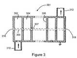
- FIG. 3shows the cross-section of the accelerating structure of a TW LINAC.
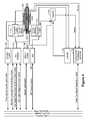
- FIG. 4illustrates a block diagram of a system for operating a multi-energy LINAC powered by a magnetron.
- FIG. 5illustrates a block diagram of a TW LINAC comprising a frequency controller.
- FIG. 6illustrates a cross-section of a target structure coupled to the LINAC accelerator structure.
- FIG. 7shows a block diagram of an example computer structure for use in the operation of a LINAC powered by a magnetron.
- a magnetronas a source of electromagnetic waves to a TW LINAC in a multi-energy operation.
- the electromagnetic wavescan be used to accelerate bunches of electrons injected into an accelerator structure to generate an output of electrons. These accelerated electrons can be directed at a target to provide highly stable, highly efficient X-ray beams.
- the LINACcan be tuned to multiple different energies to provide a highly stable, highly efficient output of electrons at each different energy. In an interleaving operation, the LINAC can provide an output of electrons that alternates between two or more different energies for each pulse.
- the energy of operation of the LINACcan be changed by varying the captured electron beam current (a measure near the output of the LINAC of the electron beam current originating from the electron gun).
- the pulse length of the beam of electrons from the electron guncan also be varied to maintain a substantially similar dose of electrons in each pulse or a similar yield of x-rays in each pulse (see Section 5.1.2).
- a magnetronas a source of electromagnetic waves for a LINAC can provide several advantages over a klystron. For example, a magnetron can be cheaper than a klystron. Also, a magnetron uses a simpler control system, since it conventionally does not utilize an external oscillator or an amplifier. Thus, a LINAC that can utilize a magnetron as the source of electromagnetic waves in an interleaved multi-energy operation can offer several advantages over a LINAC that uses a klystron.
- a magnetronSince a magnetron is an oscillator, it can be less agile with respect to frequency tuning or power level of operation than a klystron (an amplifier for which both frequency and output power can be tuned using a low power external driver). That is, it can be more difficult to modify the frequency or power level of a magnetron than a klystron.
- a system and methodis provided herein that uses a beam loading effect to provide outputs of electrons at different energies from a LINAC that receives electromagnetic waves from a magnetron.
- the system and methodneed not use the magnetron to vary the frequency or power level of an electromagnetic wave.
- the system and methodcan facilitate different energy outputs of the LINAC substantially without modification to the frequency or power level of the magnetron.
- the different energy outputs of the LINAC that receives electromagnetic waves from a magnetroncan be achieved through a beam loading effect, by changing the captured electron beam current.
- the captured electron beam currentis the beam of electrons measured near the output of the LINAC.
- the amount of the captured electron beam currentcan be controlled, e.g., by varying the electron beam current originating at the electron gun.
- the captured beam currenttypically has a magnitude less than the electron beam current originating from the electron gun.
- the captured beam currentcan be up to about 15%, about 20%, about 25%, about 30%, about 35%, about 40%, about 45%, or up to about 50% or more of the electron beam from the electron gun.
- the difference between the captured electron beam current and the electron beam current originating at the electron guncan depend on the structure of the LINAC and can be readily ascertained by one of ordinary skill in the art. Furthermore, it would be readily apparent to one of ordinary skill in the art how to determine, for a given LINAC, the amount of captured beam current that can be obtained for a given amount of electron beam current originating from the electron gun. For example, a skilled practitioner can operate a LINAC at several different levels of electron beam current originating at the electron gun and measure the corresponding captured electron beam current. The captured beam current can be measured by a monitor positioned near the output of the LINAC.
- the accelerating electron beamcan induce a beam loaded field in the LINAC having a phase that opposes the acceleration applied by the electromagnetic wave coupled into the LINAC from the magnetron. That is, beam loading can induce a beam loaded field that acts to decelerate the electron beam.
- the amplitude of the beam induced fieldvaries monotonically with the electron beam current.
- a higher electron beam currentcan induce electric fields of higher amplitude that oppose the acceleration applied by the electromagnetic wave coupled into the LINAC, and result in the electron beam experiencing less acceleration.
- the lower strength electromagnetic waveaccelerates the electron bunches at a slower rate than the higher strength electromagnetic waves.
- the effect of beam loadingis essentially to decrease the amplitude of the electromagnetic wave accelerating the electron beam.
- a desirable result of increasing the electron beam current (and hence the effect of beam loading) to lower the energy of the output electronsis that the increased current can partially or fully compensate for the lower x-ray yield produced by the lower energy.
- FIG. 1AThe characteristics of the beam loaded field in a constant gradient TW LINAC with a forward wave is illustrated in FIG. 1A .
- FIG. 1Billustrates the characteristics of the beam loaded field in a standing (SW) LINAC.
- FIG. 1Aillustrates a constant field E 0 (horizontal line) in the TW LINAC in the absence of beam loading.
- the character of the beam induced field in the TW LINACresults from the fact that the beam is synchronous only with one forward wave, and each unit length of the LINAC adds a roughly equal increment of field to that wave.
- the field increments(not power increments) add monotonically.
- the output coupleris matched for the synchronous wave, and the beam induced field varies monotonically with distance L Z along the length of the LINAC.
- the magnitude of the beam induced field E Beam Inducedvaries monotonically with length along the LINAC structure L Z , increasing in magnitude with L Z , but in the negative direction.
- the monotonic rise in magnitude of E Beam Inducedis a reasonable approximation of the field near the buncher region of a constant gradient LINAC structure.
- the phase of the beam induced fieldis such that it decelerates the synchronous beam and thus can be approximated as roughly 180 degrees out of phase with the unloaded field (E 0 ).
- the beam induced fieldvaries monotonically in magnitude and is opposite to E 0 (thus it is shown in FIG. 1A as negative).
- An electron with a kinetic energy of 1 ⁇ 2 MeVhas a velocity of approximately 85% of the velocity of light. It can take an infinite amount of energy to accelerate an electron that last 15% to the velocity of light.
- a value of electron energy of 1 ⁇ 2 MeVcan be determined as a dividing line between non-relativistic and relativistic velocity of the electrons. In other example systems, the dividing line between non-relativistic and relativistic velocity of the electrons can be determined to be greater than or less than 1 ⁇ 2 MeV.
- the dashed vertical line in FIG. 1Acan serve as a demarcation for when the electrons attain relativistic speeds.
- the velocity of the electronsis less sensitive to the energy of the beam.
- the lagging of the electron beam behind the crest of the electromagnetic wave for a 6 MeV beam relative to a 9 MeV beamoccurs in the first 1 ⁇ 2 MeV of acceleration.
- the field difference (between the unloaded field and the beam loaded field) in the first 1 ⁇ 2 MeV in a TW LINACcan be very small (identified by the shaded region in FIG. 1A ).
- the phase shiftcan be small, therefore, the beam loading effect can produce less phase error in a TW LINAC.
- the frequencyis adjusted to put the high energy beam ahead of the crest of the electromagnetic wave by about the same amount as the lower energy beam is behind the crest, both beams can be close enough to the crest to provide an output of electrons with reasonable spectra and stability.
- FIG. 1Billustrates the characteristics of the beam loaded field in a SW LINAC.
- SW LINACthere are two waves which are synchronous with the beam: (1) a forward wave in which there can be roughly no phase shift, relative to the beam, from cavity to cavity (of the LINAC structure), and (2) a backward wave in which there can be a roughly 2n ⁇ phase shift (where n is an integer), relative to the beam, from cavity to cavity.
- the beamexcites both forward and backward waves equally, and thus excites a (beam loaded) standing wave that is approximately 180° out of phase of the unloaded field.
- the beam induced field E Beam Inducedis illustrated in FIG.
- Systems and methodsare provided for operating a TW LINAC that uses electromagnetic waves received from a magnetron to accelerate electrons so that the TW LINAC provides outputs of electrons at two or more different energies.
- FIG. 2shows a flow chart of steps in an example operation of a TW LINAC that uses electromagnetic waves received from a magnetron to accelerate electrons.
- a first electromagnetic wavegenerated by a magnetron
- an electron gunejects into an input of the accelerator structure of the LINAC a first set of electrons from the electron gun (which can be obtained, for example, by applying a first gun current command to the electron gun).
- the first set of electronsis accelerated to a first range of output energies using the electromagnetic wave generated by the magnetron, and output at a first captured electron beam current.
- a second electromagnetic wavegenerated by a magnetron, is coupled into the accelerator structure of the LINAC.
- the second electromagnetic wavecan have substantially the same frequency and substantially the same amplitude as the first electromagnetic wave of step 20 .
- the second electromagnetic wavecan have a second frequency that is slightly different from the first frequency of the first electromagnetic wave of step 20 , e.g., that varies by less than 0.002% of that of the first electromagnetic wave.
- the electron gunejects a second set of electrons (which can be obtained, for example, by applying a second gun current command to the electron gun) into the input of the accelerator structure.
- the second gun currentcan be different from the first gun current.
- the second set of electronsis accelerated to a second range of output energies using the electromagnetic wave generated by the magnetron and output at a second captured electron beam current.
- the second captured electron beam currentcan be different from the first captured electron beam current.
- the central value (e.g., the mean value or median value) of the second range of electron output energiescan be different from the central value (the respective mean value or median value) of the first range of electron output energies when the second gun current is different from the first gun current, or when the second captured electron beam current is different from the first captured electron beam current.
- the central values of the first and second ranges of electron output energiesare different if they differ by greater than about 1% in magnitude, greater than about 2% in magnitude, greater than about 5% in magnitude, greater than about 10% in magnitude, or more. Steps 20 - 26 can be repeated a number of times during operation of the LINAC.
- the LINACin an interleaving operation, can be operated to cycle between the two different ranges of electron output energies. For example, the LINAC can be operated to alternate between about 6 MeV and about 9 MeV for each pulse, with the second captured electron beam current (which can be obtained by applying a second gun current command to the electron gun) being different from the first captured electron beam current (which can be obtained by applying a first gun current command to the electron gun), from pulse to pulse.
- the LINACcan be operated for multiple pulses with the electron gun providing a first captured electron beam current for each of the multiple pulses and each of the first set of electrons being accelerated to the first range of output energies, before the LINAC is operated for additional multiple pulses with the electron gun providing a second captured electron beam current for each of the additional multiple pulses and each of the second set of electrons being accelerated to the second range of output energies. That is, the LINAC can also be operated to provide multiple pulses at the first energy and then operated to provide multiple pulses at the second energy.
- the second captured electron beam currentcan differ from the first captured electron beam current by a fixed magnitude of electron beam current for the desired energies of operation. That is, the energy of an example LINAC can be changed by a fixed amount depending on the energy difference between the central value of the first range of electron output energies and the central value of the second range of electron output energies. In an example, a difference of output energies of about 3 MeV for the two different energies of operation can be obtained if the difference in the magnitude of the first captured beam current from the first output of electrons and the magnitude of the second captured beam current from the second output of electrons is about 160 mA.
- the value of the difference in the magnitude of the first captured beam current from the first output of electrons and the magnitude of the second captured beam current from the second output of electronscan depend on the length of the LINAC structure and the shunt impedance of the LINAC structure, and in some embodiments can be higher or lower than about 160 mA.
- the difference in magnitude of 160 mA between the first captured beam current and the second captured beam currentcan be applicable to a X-band TW LINAC having a length of about 0.5 m.
- the captured beam currentcan be up to about 15%, about 20%, about 25%, about 30%, about 35%, about 40%, about 45%, or up to about 50% or more of the electron beam from the electron gun.
- the lost electron beam(i.e., the portion of the electron beam that is not captured beam) may not contribute much to the beam loading effect.
- a captured electron beam current of about 25 mAprovides an output energy of about 9 MeV
- a captured electron beam current of about 185 mAcan provide an output energy of about 6 MeV. If the LINAC is operated at a third energy range with central value of output energy of about 7.5 MeV, the captured electron beam current would be about 105 mA.
- the magnetroncan be configured to run at a single frequency that optimizes the energy spectra of each of the different energies of operation of the LINAC.
- the LINACcan be operated at about 9 MeV and 6 MeV interleaved with the magnetron operating at a single frequency and generating electromagnetic waves of substantially the same power amplitude from pulse to pulse.
- the LINACcan be operated at about 8 MeV and 5 MeV and a good spectrum can be obtained at both energies, by just changing the captured electron beam current with the magnetron operating at the same single frequency and generating electromagnetic waves of substantially the same power amplitude from pulse to pulse.
- the LINACis operated to accelerate a first beam of electrons to a first range of energies and a second beam of electron to a second range of energies, and the central value of the second range of energies is greater than the central value of the first range of energies, then the magnitude of the second captured electron beam current would be less than the magnitude of the first captured electron beam current.
- the second captured electron beam currentcan be lower than the first captured electron beam current, for example, by a factor of about 2, about 3, about 4, about 5, about 8, about 10 or more. That is, in step 22 , a first gun current is applied to the electron gun to eject the first set of electrons from the electron gun into the input of the accelerator structure of the LINAC.
- a second gun current that is lower than the first gun currentis applied to the electron gun to eject a second set of electrons from the electron gun into the input of the accelerator structure of the LINAC.
- the output of x-rays from the two different energies of operationcan be maintained at similar x-ray intensities (at a detector). That is, the magnitude of the second gun current applied to the electron gun can be set at a value such that the second captured electron beam current bombarding the target produces substantially the same dose of x-rays as that obtained from bombarding the target with the first captured electron beam current (relative to the first gun current applied to the electron gun).
- the beam pulse length from the electron guncan be changed to maintain substantially the same electron beam charge, or alternately substantially the same x-ray yield, from pulse to pulse for the different energies of operation. That is, in step 22 , the electron gun ejects the first set of electrons from the electron gun with a first pulse length into the input of the accelerator structure of the LINAC. In step 26 , the electron gun ejects a second set of electrons from the electron gun with a second pulse length into the input of the accelerator structure of the LINAC.
- the second pulse lengthcan be longer than the first pulse length, for example, by a factor of about 2, about 3, about 4, about 5, about 8, about 10 or more.
- the change in pulse lengthalso can be used to maintain the dose of x-rays from the two different energies of operation at substantially similar x-ray intensities (at a detector).
- a LINACcan be operated at an interleaving operation between 9 MeV, 6 MeV and 3 MeV, such as for cargo inspection where it is interleaved between 9 MeV and 6 MeV to detect high atomic number (Z) objects which may be fissionable materials or shielding for radioactive materials, and interleaved between 6 MeV and 3 MeV to detect low Z explosive materials.
- Zatomic number
- the pulse length of the electron beam from the electron gun used to provide the output of electrons at the lower energycan be higher than the pulse length of the electron beam from the electron gun used to provide the output of electrons at the higher energy, for example, by a factor of about 3, about 4, about 5, or even up to about 10.
- Such differing pulse length for the two output energies of operationcan cause both x-rays of substantially similar x-ray intensities at the detector. For example, for a LINAC operating to provide outputs of electrons at 6 MeV and 9 MeV, it can take about 3 times more electrons at the 6 MeV operation to provide substantially the same x-ray yield as the electrons at the 9 MeV operation. As another example, for a LINAC operating to provide outputs of electrons at 3 MeV and 6 MeV, it can take about 6 times more electrons at the 3 MeV operation to provide substantially the same x-ray yield as the electrons at the 6 MeV operation.
- the difference in pulse lengthcan be smaller, such as by a factor of a little more than about 1, up to about 2, or up to about 3, to equalize the x-ray yields for the two energies.
- the x-ray dose per pulsealso can be controlled by changing the current of each energy beam in the same direction while maintaining a constant difference between the captured electron beam current between the different energies of operation. That is, in a specific example where a difference of output energies of about 3 MeV is obtained with a difference in captured electron beam current of about 160 mA, then the first captured electron beam current and the second captured electron beam current can both be increased or decreased by substantially the same amount to maintain the same difference between the two values.
- a simplified control systemcan be used with the systems and methods disclosed herein, to control the change of the electron gun current between pulses, which can also be used to control the captured electron beam current.
- the simplified control systemcan be used to control the beam pulse length also from pulse to pulse. That is, in an example system, one or more control units can be interfaced with the magnetron, the electron gun, and the LINAC structure. The one or more control units interfaced with the magnetron can issue one or more commands to cause the magnetron to generate the first and second electromagnetic waves to the LINAC (see steps 20 and 24 of FIG. 2 , respectively).
- the one or more control units interfaced with the electron guncan issue one or more commands to cause the first gun current and second gun current to be applied to the electron gun, and to cause the electron gun to eject the first set of electrons and second set of electrons into the accelerator structure (see steps 22 and 26 of FIG. 2 , respectively).
- a magnetronfunctions as a high-power oscillator, to generate electromagnetic waves (usually microwave) pulses of several microseconds duration and with a repetition rate of several hundred pulses per second.
- the frequency of the electromagnetic waves within each pulsecan be typically about 3,000 MHz (S-band) or about 9,000 MHz (X-band).
- S-band3,000 MHz
- X-band9,000 MHz
- 800 to 1500 MHz (L-band) pulsescan be used.
- the magnetroncan be any magnetron deemed suitable by one of skill.
- the CTL X-band pulsed magnetronmodel number PM-1100X (L3 Communications, Applied Technologies, Watsonville, Calif.) can be used.
- the magnetronhas a cylindrical construction, having a centrally disposed cathode and an outer anode, with resonant cavities machined out of a solid piece of copper.
- the space between the centrally disposed cathode and the outer anodecan be evacuated.
- the cathodecan be heated by an inner filament; the electrons are generated by thermionic emission.
- a static magnetic fieldcan be applied perpendicular to the plane of the cross-section of the cavities (for example, perpendicular to a pulsed DC electric field), and a pulsed DC electric field applied between the cathode and the anode.
- the electrons emitted from the cathodecan be accelerated toward the anode by the action of the pulsed DC electric field and under the influence of the magnetic field.
- the electronscan be moved in a complex spiraling motion towards the resonant cavities, causing them to radiate electromagnetic radiation at a frequency in the microwave region of the electromagnetic spectrum.
- the generated microwave pulsescan be coupled into to an accelerator structure via a transfer waveguide.
- Magnetronscan operate at 1 or 2 MW peak power output to power low-energy LINACs (6 MV or less). Magnetrons can be relatively inexpensive and can be made compact, which can be an advantage for many applications. Continuous-wave magnetron devices can have an output power as high as about 100 kW at 1 GHz with efficiencies of about 75-85 percent, while pulsed devices can operate at about 60-77 percent efficiency. Magnetrons can be used in single-section low energy linear accelerators that may not be sensitive to phase. Feedback systems can be interfaced with the magnetron to stabilize the frequency and power of the electromagnetic wave output.
- FIG. 3illustrates an example accelerating structure of a TW LINAC.
- FIG. 3illustrates an example cross-section of a forward wave TW LINAC structure.
- accelerating structure 301has a cylindrical cross-section.
- the TW LINACcomprises an accelerating structure 301 that has a longitudinal passageway 300 and a plurality of cavities 302 , 304 positioned along the central bore of the accelerating structure, and separated by transverse panels 306 .
- Transverse panels 306can be metallic discs.
- Each transverse panel 306has central orifices 307 aligned along the longitudinal axis of the accelerating structure 301 to form longitudinal passageway 300 running down the center of the accelerating structure.
- the electromagnetic waveis coupled through these central orifices.
- a traveling wave LINACcan have at least 5, at least 10, at least 15, at least 20, at least 25, at least 30, at least 35, at least 40, or more cavities.
- transverse panel 306can be a disc.
- the electromagnetic waveis fed in from input waveguide 310 to accelerating structure 301 .
- the electromagnetic waveflows downstream of the electron beam and is coupled out into waveguide 312 after one passage through accelerating structure 301 .
- a beam of electrons injected into an input orifice 316 of the longitudinal passageway 300 of the TW LINACis accelerated by the electromagnetic wave along the longitudinal passageway 300 and emitted from an output orifice 318 .
- the emitted electron beamcan be directed at an x-ray target (not shown). The generation of x-rays and examples of targets are discussed in Section 5.5 below.
- FIG. 4illustrates a block diagram of an exemplary multi-energy LINAC 34 and operating system components.
- the illustrated operating system for a LINACincludes a control interface through which a user can adjust settings, control operation, etc. of the LINAC.
- the control interfacecommunicates with a programmable logic controller (PLC) and/or a personal computer (PC) that is connected to a signal backplane.
- PLCprogrammable logic controller
- PCpersonal computer
- the signal backplaneprovides control signals to multiple different components of the LINAC based on instructions received from the PLC, PC and/or control interface.
- a controller 431receives tuning control information from the signal backplane.
- the controller 431can be interfaced with a magnetron 432 , an electron gun 433 , and/or one or more other components of the LINAC 434 .
- LINAC 434is a TW LINAC where the controller 431 interfaces with the input waveguide 435 and the output waveguide 436 .
- a waveguide 435couples the magnetron 432 to an input of the LINAC 434 .
- the waveguide 435includes a waveguide coupler and a vacuum window.
- the waveguide 435carries high powered electromagnetic waves (carrier waves) generated by the magnetron 432 to the accelerator structure of the LINAC 434 .
- the waveguide coupler of waveguide 435can sample a portion of the electromagnetic wave power to the input of the LINAC.
- a waveguide 436 that includes a waveguide coupler and a vacuum windowcouples the output of the accelerator structure of the LINAC 434 to the RF load.
- Waveguide 435 or waveguide 436can be a rectangular or circular metallic pipe that is configured to optimally guide waves in the frequencies that are used to accelerate electrons within the LINAC without significant loss in intensity.
- the metallic pipecan be a low-Z, high conductivity, material such as copper.
- the waveguidecan be filled with SF 6 gas. Alternatively, the waveguides can be evacuated.
- the vacuum windowpermits the high power electromagnetic waves to enter the input of the LINAC 434 while separating the evacuated interior of the LINAC 434 from its gas filled or evacuated exterior.
- a gun modulator 437controls an electron gun (not shown) that fires electrons into the LINAC 434 .
- the electron guncan be any electron gun deemed suitable by one of skill. For example, the L3, model number M592 (L3 communications, Electron Devices, San Carlos, Calif.) can be used.
- the gun modulator 437receives grid drive level and current feedback control signal information from the signal backplane.
- the gun modulator 437further receives gun trigger pulses and delay control pulse and gun heater voltage and HV level control from the signal backplane.
- the gun modulator 437controls the electron gun by instructing it when and how to fire (e.g., including repetition rate and grid drive level to use).
- the gun modulator 437can cause the electron gun to fire the electrons at a pulse repetition rate that corresponds to the pulse repetition rate of the high power electromagnetic waves (carrier waves) supplied by the magnetron 432 .
- One or more controllers interfaced with the gun modulator 437 or electron guncan provide instructions to cause the electron gun to deliver a beam current to the accelerator, or to determine the pulse length of the injection of electrons.
- An example electron gunincludes an anode, a grid, a cathode and a filament.
- the filamentis heated to cause the cathode to release electrons, which are accelerated away from the cathode and towards the anode at high speed.
- the focus electrode and the anodecan focus the stream of emitted electrons into a beam of a controlled diameter.
- the gridcan be positioned between the anode and the cathode.
- the electron gunis followed by a buncher that is located after the electron gun and is typically integral within the accelerating structure of the LINAC 434 .
- the buncheris composed of the first few cells of the accelerating structure of the LINAC 434 .
- the buncherpacks the electrons fired by the electron gun into bunches and produces an initial acceleration. Bunching is achieved because the electrons receive more energy from the electromagnetic wave (more acceleration) depending on how near they are to the crest of the electromagnetic wave. Therefore, electrons riding higher on the electromagnetic wave catch up to slower electrons that are riding lower on the electromagnetic wave.
- the buncherapplies the high power electromagnetic waves provided by the magnetron 432 to the electron bunch to achieve electron bunching and the initial acceleration.
- High power electromagnetic wavesare injected into the LINAC 434 from the magnetron 432 via the waveguide 435 . Electrons to be accelerated are injected into the LINAC 434 by the electron gun. The electrons enter the LINAC 434 and are typically bunched in the first few cells of the LINAC 434 (which may comprise the buncher).
- the LINAC 434is a vacuum tube that includes a sequence of tuned cavities separated by irises. The tuned cavities of the LINAC 434 are bounded by conducting materials such as copper to keep the energy of the high power electromagnetic waves from radiating away from the LINAC 434 , and to form a propagating mode with a high longitudinal electric field on the axis of the accelerator structure.
- each successive cavityis longer than its predecessor to account for the increasing particle speed.
- the electronsreach about 98% of the velocity of light and the rest of the cells are all the same length.
- the basic design criterionis that the phase velocity of the electromagnetic waves matches the particle velocity at the locations of the cavities in the LINAC 434 where acceleration (but not bunching) occurs.
- the electron beamcan be directed at a target, such as a tungsten target, that can be positioned at the end of the LINAC 434 .
- a targetsuch as a tungsten target
- the bombardment of the target by the electron beamgenerates a beam of x-rays (discussed in Section 5.5 below).
- the electronscan be accelerated to different energies using the beam loading effect as discussed in Sections 5.1.1 above before they strike a target.
- the electronscan be alternately accelerated to two or more different output energies, e.g., to about 3 MeV, to about 6 MeV and to about 9 MeV.
- the TW LINACcan be operated in the X-band (e.g., at an RF frequency between 8 GHz and 12.4 GHz).
- the high operating frequencyrelative to a conventional S-band LINAC, can reduce the length of the LINAC 434 by approximately a factor of three, for a given number of accelerating cavities, with a concomitant reduction in mass and weight.
- the components of the TW LINACcan be packaged in a relatively compact assembly.
- the TW LINACcan operate in the S-band.
- Such a TW LINACcan require a larger assembly, but can provide a higher energy X-ray beam (e.g., up to about 18 MeV) with commercially available high power electromagnetic wave sources.
- a focusing system 438controls powerful electromagnets that surround the LINAC 434 .
- the focusing system 438receives a current level control from the signal backplane, and controls a current level of focusing coils to focus an electron beam that travels through the LINAC 434 .
- the focusing system 438is designed to focus the beam to concentrate the electrons to a specified diameter beam that is able to strike a small area of the target.
- the beamcan be focused and aligned by controlling the current that is supplied to the electromagnet.
- the focusing currentcan remain constant between pulses, and the current can be maintained at a value which allows the electromagnet to substantially focus the beam for each of the different energies of operation.
- a sulfur hexafluoride (SF 6 ) controller 439receives pressure control information from the backplane and can control an amount (e.g., at a specified pressure) of SF 6 gas, a dielectric gas and insulating material, that can be pumped into the waveguides 435 and 436 .
- the SF 6 controllerreceives pressure control information from the backplane and uses the received information to control the pressure of SF 6 gas that is supplied to the waveguide.
- the SF 6 gascan increase the amount of peak power that can be transmitted through waveguides 435 and 436 , and can increase the voltage rating of the LINAC.
- a vacuum system 440(e.g., an ion pump vacuum system) can be used to maintain a vacuum in both the magnetron 432 and the LINAC 434 , and to report current vacuum levels (pressure) to the signal backplane.
- a vacuum systemalso can be used to generate a vacuum in portions of the waveguides 435 and 436 .
- a cooling system/temperature control unit 441can be used to monitor the temperature of one or more components of the system and to control a cooling system to maintain a constant temperature of these components.
- the cooling systemcan circulate water or other coolant to regions that need to be cooled, such as the magnetron 432 and the LINAC 434 .
- the temperature of the metal of the LINAC and the magnetronmay rise as much as 10° C. when the LINAC is operated at a high repetition rate, which can contribute to a drift in the electromagnetic wave.
- the magnetron oscillating frequencymust be tuned to keep the RF phase difference constant from the input to the output of the LINAC.
- FIG. 5shows a block diagram of an embodiment of a TW LINAC system that includes a magnetron 502 , a tuner 504 interfaced with the magnetron 502 , a frequency controller 506 , an electron gun 508 , and an accelerator structure 510 .
- the frequency controller 506can be used to measure the phase of the electromagnetic wave near the output coupler relative to the phase of the electromagnetic wave near the input coupler.
- the frequency controller 506includes a controller and a phase comparator.
- the phase comparator of frequency controller 506can compare the electromagnetic wave at the input of the accelerator structure 510 (P 1 ) and at the output of the accelerator structure 510 (P 2 ) and provides a measure of the phase shift ( ⁇ P) to the controller of frequency controller 506 .
- the frequency controller 506can be used to maintain the phase shift through the LINAC at the same set point for the different energies of operation of the LINAC. Specifically, the frequency controller 506 can transmit a signal to the tuner 504 to tune the magnetron in order to maintain the phase shift of the electromagnetic wave at the set point. For example, if the measured phase shift of the first electromagnetic wave (generated at a first frequency) is not at the set point, the frequency controller 506 can transmit a signal to the tuner 504 to tune the magnetron to generate a second electromagnetic wave at a modified frequency (i.e., to a second frequency that is not equal to the first frequency) to cause the phase shift of the second electromagnetic wave to be closer to the set point.
- a modified frequencyi.e., to a second frequency that is not equal to the first frequency
- the first frequency and the second frequencyare different if they differ by greater than about 0.001% in magnitude, greater than about 0.002% in magnitude, or more. If the measured phase shift of the first electromagnetic wave (generated at a first frequency) is at the set point, the frequency controller 506 can transmit a signal to the tuner 504 so that the magnetron to generate the second electromagnetic wave at substantially the same frequency as the first electromagnetic wave.
- the first frequency and the second frequencycan be substantially the same frequency if they differ by less than about 0.001%. That is, a measurement of the phase difference between P 1 and P 2 can cause the magnetron to be tuned to alter its operating frequency, if necessary, and thereby maintain a specific phase shift of the electromagnetic waves through the accelerator structure.
- the signal from the frequency controller 506 to the magnetroncan ultimately result in maintaining the phase shift of the electromagnetic waves through the accelerator structure at a set point, based on the magnitude of the phase shift detected by the frequency controller.
- the frequency controllercan be an automatic frequency controller (AFC).
- AFCautomatic frequency controller
- the frequency controlleris illustrated in FIG. 5 as comprising a controller and a phase comparator as an integral unit.
- the frequency controller 506can comprise the controller and phase comparator as separate units.
- the frequency of the electromagnetic wave generated by the magnetroncan be tuned mechanically.
- a tuning pin or a tuning slug positioned in communication with the body of the magnetroncan be moved in or out of the body of the magnetron to tune its operating frequency.
- Tuner 504can include a motor drive that moves the tuning pin or tuning slug to tune the magnetron mechanically.
- the mechanical tuningcan be used to maintain the stability of the performance of the magnetron.
- ⁇ fcan be a difference on the order of about one or a few parts in 10,000 of a frequency in kHz.
- ⁇ fcan be a difference on the order of about 0.01 MHz or more, about 0.03 MHz or more, about 0.05 MHz or more, about 0.08 MHz or more, about 0.1 MHz or more.
- the frequency controllercan be used to maintain the stability of the output energy and electron dose stability.
- the magnetroncan be tuned to operate at a range of values ( ⁇ f) around a single frequency (f) that provides for a maximized output of the LINAC at all of the different energies of operation.
- the magnetroncan be operated to generate electromagnetic waves at values within a range ( ⁇ f) around a single frequency (f) such that the electron bunches are accelerated on average slightly ahead of the peak of the electromagnetic wave during the 9 MeV operation and are accelerated on average slightly behind the peak of the electromagnetic wave during the 6 MeV.
- the single frequency of operation of the magnetroncan be determined by first finding an intermediate electron gun current between those used for the two different energies of operation, for which adjusting the frequency of the magnetron to optimize the x-ray yield of the LINAC provides acceptable energy spectrum and stability for both the highest energy operation and the lowest energy.
- the intermediate electron gun currentcan be, but is not limited to, an average or median of the highest electron gun current and the lowest electron gun current for a two-energy operation or for operation at three or more different energies.
- the single frequency of operation of the magnetron, and the range of values ( 60 around the single frequency,can be determined as the frequency (and ⁇ f) that maximizes a x-ray yield of the LINAC for that intermediate electron gun current.
- the frequency controllercan facilitate stable operation during rapid switching of a multi-energy interleaved operation of the TW LINAC.
- the frequency controllercan be used to correct for the effect of rapid thermalization of the TW LINAC accelerator structure when the system is stepping from standby to full power, drifts in the temperature of the accelerator structure cooling water, or drifts in the frequency of the magnetron.
- FIG. 6illustrates a cross-section of a target structure 650 coupled to the LINAC 434 (partially shown).
- the target structure 650includes a target 652 to perform the principal conversion of electron energy to x-rays.
- the target 652may be, for example, an alloy of tungsten and rhenium, where the tungsten is the principle source of x-rays and the rhenium provides thermal and electrical conductivity and improved ductility for easier machining and longer lifetime with thermal shocks.
- the target 652may include one or more target materials having an atomic number approximately greater than or equal to 70 to provide efficient x-ray generation.
- the x-ray targetcan include a low-Z material such as but not limited to copper, which can avoid or reduce generation of neutrons when bombarded by the output electrons.
- the target 652may be mounted in a metallic holder 654 , which may be a good thermal and electrical conductor, such as copper.
- the holder 654may include an electron collector 656 to collect electrons that are not stopped within the target 652 and/or that are generated within the target 652 .
- the collector 656may be a block of electron absorbing material such as a conductive graphite based compound.
- the collector 656may be made of one or more materials with a low atomic number, for example, an atomic number approximately less than or equal to 6, to provide both electron absorption and transparency to x-rays generated by the target 652 .
- the collector 656may be electrically isolated from a holder by an insulating layer 658 (e.g., a layer of anodized aluminum).
- the collector 656is a heavily anodized aluminum slug. Measurement of the current collected in the collector can be used to provide an indication of the energy of the electron beam (including the captured electron beam).
- a collimator 659can be attached to the target structure.
- the collimator 659shapes the X-ray beam into an appropriate shape. For example, if the LINAC is being used as an X-ray source for a cargo inspection system, the collimator 659 may form the beam into a fan shape.
- the X-ray beammay then penetrate a target (e.g., a cargo container), and a detector at an opposite end of the target may receive X-rays that have not been absorbed or scattered.
- the received X-raysmay be used to determine properties of the target (e.g., contents of a cargo container).
- An x-ray intensity monitor 651can be used to monitor the yield of the x-ray during operation (see FIG. 6 ).
- a non-limiting example of an x-ray intensity monitor 661is an ion chamber.
- the x-ray intensity monitor 651can be positioned at or near the x-ray source, for example, facing the target.
- the controller 431can transmit a signal to a controller of the electron gun to cause a higher (or lower) beam current to be applied to the electron gun (as discussed above in Section 5.1) in order to maintain a substantially similar dose of x-rays from pulse to pulse.
- the controller 431can transmit a signal to a controller of the electron gun to cause the electron gun to provide a beam of electrons at a longer (or shorter) pulse length (as discussed above in Section 5.1) in order to maintain a substantially similar dose of x-rays from pulse to pulse.
- x-rayscan be generated from the bombardment of a target material by the accelerated electron beam or electron bunches from a LINAC.
- the x-rayscan be generated by two different mechanisms. In the first mechanisms, collision of the electrons from the LINAC with an atom of a target can impart enough energy so that electrons from the atom's lower energy levels (inner shell) escape the atom, leaving vacancies in the lower energy levels. Electrons in the higher energy levels of the atom descend to the lower energy level to fill the vacancies, and emit their excess energy as x-ray photons.
- K-shell radiationSince the energy difference between the higher energy level and the lower energy level is a discrete value, these x-ray photons (generally referred to as k-shell radiation) appear in the x-ray spectrum as sharp lines (called characteristic lines). K-shell radiation has a signature energy that depends on the target material.
- the electron beams or bunches from the LINACare scattered by the strong electric field near the atoms of the target and give off Bremsstrahlung radiation. Bremsstrahlung radiation produces x-rays photons in a continuous spectrum, where the intensity of the x-rays increases from zero at the energy of the incident electrons.
- the highest energy x-ray that can be produced by the electrons from a LINACis the highest energy of the electrons when they are emitted from the LINAC.
- the Bremsstrahlung radiationcan be of more interest than the characteristic lines for many applications.
- Materials useful as targets for generating x-raysinclude tungsten, certain tungsten alloys (such as but not limited to tungsten carbide, or tungsten (95%)-rhenium (5%)), molybdenum, copper, platinum and cobalt.
- Certain instrumentsthat may be used in the operation of a traveling wave LINAC include a modulator, a phase bridge, a vacuum gauge or an ion pump current gauge, an oscilloscope, and a beam current monitor.
- a modulator for the magnetrongenerates high-voltage pulses lasting a few microseconds. These high-voltage pulses can be supplied to the magnetron.
- a power supplyprovides DC voltage to the modulator, which converts this to the high-voltage pulses.
- the Solid State Magnetron Modulator-M1 or -M2can be used in connection with the magnetron.
- a gun driver or gun deckcan be used to operate the electron gun.
- a computer systemsuch as the computer system described in this section, according to the following programs and methods.
- a computer systemcan store and issue commands to facilitate modification of the electromagnetic wave frequency according to a method disclosed herein.
- a computer systemcan store and issue commands to facilitate operation of the controller of the magnetron or the controller of the electron gun according to a method disclosed herein.
- the systems and methodsmay be implemented on various types of computer architectures, such as for example on a single general purpose computer, or a parallel processing computer system, or a workstation, or on a networked system (e.g., a client-server configuration such as shown in FIG. 7 ).
- FIG. 7An exemplary computer system suitable for implementing the methods disclosed herein is illustrated in FIG. 7 .
- the computer system to implement one or more methods and systems disclosed hereincan be linked to a network link which can be, e.g., part of a local area network (“LAN”) to other, local computer systems and/or part of a wide area network (“WAN”), such as the Internet, that is connected to other, remote computer systems.
- LANlocal area network
- WANwide area network
- a software componentcan include programs that cause one or more processors to issue commands to one or more control units, which cause the one or more control units to issue commands to cause the initiation of the controller of the magnetron or the controller of the electron gun, to operate the magnetron to generate an electromagnetic wave at a frequency, and/or to operate the LINAC (including commands for coupling the electromagnetic wave into the LINAC).
- the programscan cause the system to retrieve commands for executing the steps of the methods in specified sequences, including initiating one or more controllers and operating the magnetron to generate an electromagnetic wave at a frequency, from a data store (e.g., a database).
- a data storecan be stored on a mass storage (e.g., a hard drive) or other computer readable medium and loaded into the memory of the computer, or the data store can be accessed by the computer system by means of the network.
- changing the captured beam current by about 160 mAcan result in a change in the output energy of the TW LINAC by about 3 MeV.
- a beam current of 25 mAprovides an output of about 9 MeV
- a beam current of 185 mAcan provide an output of about 6 MeV beam.
- a beam current of 105 mAcan provide a third energy beam of about 7.5 MeV.
- the X-ray dose per pulsecan be controlled by changing the pulse length of the beam from the electron gun, or by changing the current of each energy beam in the same direction while maintaining the current differences between each desired energy beam.
- the magnetroncan be run with a single frequency which optimizes the energy spectra of the different energies of operation of the TW LINAC.
- a TW LINACcan be run at two different energies, e.g., about 9 MeV and about 6 MeV interleaved, with the magnetron run at a single frequency and a single RF power amplitude.
- the TW LINACalso can be run at 8 MeV and 5 MeV, with a good spectrum at both energies, by changing the electron gun current for each different energy but maintain substantially the same frequency and power amplitude of the electromagnetic wave from the magnetron.
Landscapes
- Physics & Mathematics (AREA)
- Engineering & Computer Science (AREA)
- Plasma & Fusion (AREA)
- Spectroscopy & Molecular Physics (AREA)
- Particle Accelerators (AREA)
Abstract
Description
Claims (35)
Priority Applications (5)
| Application Number | Priority Date | Filing Date | Title |
|---|---|---|---|
| US12/697,031US8311187B2 (en) | 2010-01-29 | 2010-01-29 | Magnetron powered linear accelerator for interleaved multi-energy operation |
| PCT/US2011/022834WO2011094475A1 (en) | 2010-01-29 | 2011-01-28 | Magnetron powered linear accelerator for interleaved multi-energy operation |
| EP11702122.0AEP2529603B1 (en) | 2010-01-29 | 2011-01-28 | Magnetron powered linear accelerator for interleaved multi-energy operation |
| CN201180014973.5ACN102918933B (en) | 2010-01-29 | 2011-01-28 | For intersecting the linear accelerator that the magnetron of multi-energy operation powers |
| US13/674,739US9426876B2 (en) | 2010-01-29 | 2012-11-12 | Magnetron powered linear accelerator for interleaved multi-energy operation |
Applications Claiming Priority (1)
| Application Number | Priority Date | Filing Date | Title |
|---|---|---|---|
| US12/697,031US8311187B2 (en) | 2010-01-29 | 2010-01-29 | Magnetron powered linear accelerator for interleaved multi-energy operation |
Related Child Applications (1)
| Application Number | Title | Priority Date | Filing Date |
|---|---|---|---|
| US13/674,739ContinuationUS9426876B2 (en) | 2010-01-29 | 2012-11-12 | Magnetron powered linear accelerator for interleaved multi-energy operation |
Publications (2)
| Publication Number | Publication Date |
|---|---|
| US20110188638A1 US20110188638A1 (en) | 2011-08-04 |
| US8311187B2true US8311187B2 (en) | 2012-11-13 |
Family
ID=43857791
Family Applications (2)
| Application Number | Title | Priority Date | Filing Date |
|---|---|---|---|
| US12/697,031Active2030-10-24US8311187B2 (en) | 2010-01-29 | 2010-01-29 | Magnetron powered linear accelerator for interleaved multi-energy operation |
| US13/674,739ActiveUS9426876B2 (en) | 2010-01-29 | 2012-11-12 | Magnetron powered linear accelerator for interleaved multi-energy operation |
Family Applications After (1)
| Application Number | Title | Priority Date | Filing Date |
|---|---|---|---|
| US13/674,739ActiveUS9426876B2 (en) | 2010-01-29 | 2012-11-12 | Magnetron powered linear accelerator for interleaved multi-energy operation |
Country Status (4)
| Country | Link |
|---|---|
| US (2) | US8311187B2 (en) |
| EP (1) | EP2529603B1 (en) |
| CN (1) | CN102918933B (en) |
| WO (1) | WO2011094475A1 (en) |
Cited By (17)
| Publication number | Priority date | Publication date | Assignee | Title |
|---|---|---|---|---|
| US20110158387A1 (en)* | 2009-12-28 | 2011-06-30 | General Electric Company | Robust radiation detector and method of forming the same |
| US20120081041A1 (en)* | 2010-10-01 | 2012-04-05 | Accuray, Inc. | Traveling wave linear accelerator based x-ray source using pulse width to modulate pulse-to-pulse dosage |
| US8384314B2 (en)* | 2009-01-26 | 2013-02-26 | Accuray, Inc. | Traveling wave linear accelerator comprising a frequency controller for interleaved multi-energy operation |
| US20130315379A1 (en)* | 2010-01-29 | 2013-11-28 | Accuray, Inc. | Magnetron powered linear accelerator for interleaved multi-energy operation |
| US8836250B2 (en) | 2010-10-01 | 2014-09-16 | Accuray Incorporated | Systems and methods for cargo scanning and radiotherapy using a traveling wave linear accelerator based x-ray source using current to modulate pulse-to-pulse dosage |
| US20140294147A1 (en)* | 2013-03-15 | 2014-10-02 | Varian Medical Systems, Inc. | Systems and methods for multi-view imaging and tomography |
| US8942351B2 (en) | 2010-10-01 | 2015-01-27 | Accuray Incorporated | Systems and methods for cargo scanning and radiotherapy using a traveling wave linear accelerator based X-ray source using pulse width to modulate pulse-to-pulse dosage |
| US9031200B2 (en) | 2010-03-05 | 2015-05-12 | Accuray Incorporated | Interleaving multi-energy x-ray energy operation of a standing wave linear accelerator |
| US9167681B2 (en) | 2010-10-01 | 2015-10-20 | Accuray, Inc. | Traveling wave linear accelerator based x-ray source using current to modulate pulse-to-pulse dosage |
| US9326366B2 (en) | 2013-03-14 | 2016-04-26 | The Board Of Trustees Of The Leland Stanford Junior University | Intra pulse multi-energy method and apparatus based on RF linac and X-ray source |
| US20160133428A1 (en)* | 2014-11-12 | 2016-05-12 | Schlumberger Technology Corporation | Radiation Generator With Frustoconical Electrode Configuration |
| US9805904B2 (en) | 2014-11-12 | 2017-10-31 | Schlumberger Technology Corporation | Radiation generator with field shaping electrode |
| US10367508B1 (en)* | 2018-05-18 | 2019-07-30 | Varex Imaging Corporation | Configurable linear accelerator trigger distribution system and method |
| US10568196B1 (en)* | 2016-11-21 | 2020-02-18 | Triad National Security, Llc | Compact, high-efficiency accelerators driven by low-voltage solid-state amplifiers |
| US20210204390A1 (en)* | 2019-12-25 | 2021-07-01 | Nuctech Company Limited | Method, apparatus and system for controlling standing wave linear accelerator |
| US20230262870A1 (en)* | 2021-08-17 | 2023-08-17 | Omega-P R&D, Inc. | A compact cyclotron resonance high-power acceleration for electrons |
| US20230293909A1 (en)* | 2022-03-17 | 2023-09-21 | Varian Medical Systems, Inc. | High dose rate radiotherapy, system and method |
Families Citing this family (15)
| Publication number | Priority date | Publication date | Assignee | Title |
|---|---|---|---|---|
| JP2012209119A (en)* | 2011-03-29 | 2012-10-25 | Mitsubishi Heavy Ind Ltd | X-ray generator and control method thereof |
| DE102011075210B4 (en) | 2011-05-04 | 2016-03-24 | Siemens Aktiengesellschaft | linear accelerator |
| WO2013043895A1 (en)* | 2011-09-20 | 2013-03-28 | Muons, Inc. | Method and apparatus for high-power 650 mhz continuous wave (cw) magnetron for intensity frontier superconducting accelerators |
| US9246495B2 (en) | 2012-03-21 | 2016-01-26 | Siemens Aktiengesellschaft | Resonator arrangement and method for exciting a resonator |
| CN103237378B (en)* | 2013-05-13 | 2014-09-10 | 南京三乐电子信息产业集团有限公司 | L-waveband high-power microwave energy generator |
| US9622333B2 (en)* | 2014-02-27 | 2017-04-11 | Etm Electromatic, Inc | Linear accelerator system with stable interleaved and intermittent pulsing |
| US9661734B2 (en) | 2014-02-27 | 2017-05-23 | ETM Electromatic, Inc. | Linear accelerator system with stable interleaved and intermittent pulsing |
| US10306745B2 (en)* | 2014-12-08 | 2019-05-28 | Hitachi, Ltd. | Accelerator and particle beam irradiation system |
| CN105916285B (en)* | 2016-06-30 | 2018-01-30 | 中国科学院上海应用物理研究所 | A kind of dual energy electron linear accelerator based on hybrid traveling wave accelerating structure |
| US10314157B1 (en)* | 2016-09-06 | 2019-06-04 | Triad National Security, Llc | Resonant Klynac (combined klystron and linac in a bi-resonant structure) |
| WO2018175804A1 (en)* | 2017-03-24 | 2018-09-27 | Radiabeam Technologies, Llc | Compact linear accelerator with accelerating waveguide |
| GB2588425B (en)* | 2019-10-23 | 2021-10-27 | Elekta ltd | Magnetron condition monitoring |
| DE102020212200B3 (en) | 2020-09-28 | 2022-03-17 | Siemens Healthcare Gmbh | Method for electron beam deflection using a magnet unit of a linear accelerator system, linear accelerator system, MeV radiation device and computer program product for carrying out the method |
| DE102020214128B4 (en)* | 2020-11-10 | 2022-06-02 | Siemens Healthcare Gmbh | Rules of an X-ray pulse chain generated by a linear accelerator system |
| CN116209132A (en)* | 2023-04-10 | 2023-06-02 | 北京机械工业自动化研究所有限公司 | An X-band Lightweight Accelerator Automatic Frequency Control System |
Citations (33)
| Publication number | Priority date | Publication date | Assignee | Title |
|---|---|---|---|---|
| US2920228A (en) | 1954-12-13 | 1960-01-05 | Univ Leland Stanford Junior | Variable output linear accelerator |
| US2993141A (en) | 1958-02-10 | 1961-07-18 | Richard F Post | Producing bunched electron beams |
| US3820035A (en) | 1973-02-26 | 1974-06-25 | Varian Associates | Microwave automatic frequency control circuit |
| US4286192A (en) | 1979-10-12 | 1981-08-25 | Varian Associates, Inc. | Variable energy standing wave linear accelerator structure |
| US4382208A (en) | 1980-07-28 | 1983-05-03 | Varian Associates, Inc. | Variable field coupled cavity resonator circuit |
| US4629938A (en) | 1985-03-29 | 1986-12-16 | Varian Associates, Inc. | Standing wave linear accelerator having non-resonant side cavity |
| US4713581A (en) | 1983-08-09 | 1987-12-15 | Haimson Research Corporation | Method and apparatus for accelerating a particle beam |
| US5796314A (en) | 1997-05-01 | 1998-08-18 | Stanford University | Active high-power RF switch and pulse compression system |
| US5801598A (en) | 1996-05-01 | 1998-09-01 | Stanford University | High-power RF load |
| US5949811A (en) | 1996-10-08 | 1999-09-07 | Hitachi Medical Corporation | X-ray apparatus |
| US6366641B1 (en) | 2001-05-25 | 2002-04-02 | Siemens Medical Solutions Usa, Inc. | Reducing dark current in a standing wave linear accelerator |
| US6459761B1 (en) | 2000-02-10 | 2002-10-01 | American Science And Engineering, Inc. | Spectrally shaped x-ray inspection system |
| US6459762B1 (en) | 2001-03-13 | 2002-10-01 | Ro Inventions I, Llc | Method for producing a range of therapeutic radiation energy levels |
| US20050057198A1 (en) | 2003-08-22 | 2005-03-17 | Hanna Samy M. | Electronic energy switch for particle accelerator |
| US7005809B2 (en) | 2003-11-26 | 2006-02-28 | Siemens Medical Solutions Usa, Inc. | Energy switch for particle accelerator |
| US7130371B2 (en) | 2002-09-27 | 2006-10-31 | Scantech Holdings, Llc | System for alternately pulsing energy of accelerated electrons bombarding a conversion target |
| US20070035260A1 (en) | 2005-08-09 | 2007-02-15 | Siemens Medical Solutions Usa, Inc. | Dual-plunger energy switch |
| US7202486B2 (en) | 2004-08-04 | 2007-04-10 | Standard Imaging, Inc. | Treatment planning tool for multi-energy electron beam radiotherapy |
| US20070215813A1 (en) | 2006-03-17 | 2007-09-20 | Varian Medical Systems Technologies, Inc. | Electronic energy switch |
| US20070248214A1 (en) | 2006-04-25 | 2007-10-25 | Accuray Incorporated | Energy monitoring target for x-ray dose-rate control |
| WO2007134514A1 (en) | 2006-05-19 | 2007-11-29 | Tsinghua University | Device method and material identifying system for producing x-ray having different energy |
| US20080037843A1 (en) | 2006-08-11 | 2008-02-14 | Accuray Incorporated | Image segmentation for DRR generation and image registration |
| JP2008198522A (en) | 2007-02-14 | 2008-08-28 | Univ Of Tokyo | X-ray source |
| JP2008218053A (en) | 2007-02-28 | 2008-09-18 | Accuthera Inc | Acceleration device and x-ray generator using the acceleration device |
| WO2009080080A1 (en) | 2007-12-21 | 2009-07-02 | Elekta Ab (Publ) | X-ray apparatus |
| US7580505B2 (en) | 2005-12-31 | 2009-08-25 | Tsinghua University | Method for inspecting object using multi-energy radiations and apparatus thereof |
| US7645994B2 (en) | 2005-12-31 | 2010-01-12 | Tsinghua University | Device for outputting high and/or low energy X-rays |
| US20100034355A1 (en) | 2008-08-11 | 2010-02-11 | Langeveld Willem G J | Systems and Methods for Using An Intensity-Modulated X-Ray Source |
| WO2010019228A2 (en) | 2008-08-12 | 2010-02-18 | Varian Medical Systems, Inc. | Interlaced multi-energy radiation sources |
| US20100111388A1 (en) | 2003-10-15 | 2010-05-06 | Varian Medical Systems, Inc. | Multi-energy x-ray source |
| US20100188027A1 (en) | 2009-01-26 | 2010-07-29 | Accuray, Inc. | Traveling wave linear accelerator comprising a frequency controller for interleaved multi-energy operation |
| US20110006708A1 (en) | 2009-07-08 | 2011-01-13 | Ching-Hung Ho | Interleaving multi-energy x-ray energy operation of a standing wave linear accelerator using electronic switches |
| US7881424B2 (en) | 2007-03-14 | 2011-02-01 | Tsinghua University | Method for calibrating dual-energy CT system and method of image reconstruction |
Family Cites Families (36)
| Publication number | Priority date | Publication date | Assignee | Title |
|---|---|---|---|---|
| US3873839A (en) | 1974-04-10 | 1975-03-25 | Atomic Energy Commission | High speed linac-beam analyzer |
| US4118653A (en) | 1976-12-22 | 1978-10-03 | Varian Associates, Inc. | Variable energy highly efficient linear accelerator |
| US4835446A (en) | 1987-09-23 | 1989-05-30 | Cornell Research Foundation, Inc. | High field gradient particle accelerator |
| US5619042A (en)* | 1995-07-20 | 1997-04-08 | Siemens Medical Systems, Inc. | System and method for regulating delivered radiation in a radiation-emitting device |
| JPH11253563A (en) | 1998-03-10 | 1999-09-21 | Hitachi Ltd | Charged particle beam irradiation method and apparatus |
| US20080211431A1 (en) | 2000-02-10 | 2008-09-04 | American Science And Engineering, Inc. | Pulse-to-Pulse-Switchable Multiple-Energy Linear Accelerators Based on Fast RF Power Switching |
| US6407505B1 (en) | 2001-02-01 | 2002-06-18 | Siemens Medical Solutions Usa, Inc. | Variable energy linear accelerator |
| US6493424B2 (en) | 2001-03-05 | 2002-12-10 | Siemens Medical Solutions Usa, Inc. | Multi-mode operation of a standing wave linear accelerator |
| US6465957B1 (en) | 2001-05-25 | 2002-10-15 | Siemens Medical Solutions Usa, Inc. | Standing wave linear accelerator with integral prebunching section |
| US6674254B2 (en) | 2001-08-13 | 2004-01-06 | Siemens Medical Solutions Usa, Inc. | Method and apparatus for tuning particle accelerators |
| WO2003018131A1 (en) | 2001-08-24 | 2003-03-06 | Mitsubishi Heavy Industries, Ltd. | Radiological treatment apparatus |
| US6473490B1 (en)* | 2001-09-28 | 2002-10-29 | Siemens Medical Solutions Usa, Inc. | Intensity map reconstruction for radiation therapy with a modulating multi-leaf collimator |
| US20030086527A1 (en) | 2001-11-02 | 2003-05-08 | Speiser Burton L | Radiation modulating apparatus and methods therefore |
| AU2003272744A1 (en) | 2002-09-27 | 2004-04-19 | Scantech Holdings, Llc | Particle accelerator having wide energy control range |
| US6864633B2 (en) | 2003-04-03 | 2005-03-08 | Varian Medical Systems, Inc. | X-ray source employing a compact electron beam accelerator |
| US8451974B2 (en) | 2003-04-25 | 2013-05-28 | Rapiscan Systems, Inc. | X-ray tomographic inspection system for the identification of specific target items |
| CN1455635A (en)* | 2003-06-06 | 2003-11-12 | 南京大学 | Energy-adjustable electronic linear accelerator |
| JP4298399B2 (en) | 2003-06-26 | 2009-07-15 | キヤノン株式会社 | Electron beam apparatus and electron beam drawing apparatus using the electron beam apparatus |
| US7110500B2 (en) | 2003-09-12 | 2006-09-19 | Leek Paul H | Multiple energy x-ray source and inspection apparatus employing same |
| US7339320B1 (en) | 2003-12-24 | 2008-03-04 | Varian Medical Systems Technologies, Inc. | Standing wave particle beam accelerator |
| US7250618B2 (en) | 2005-02-02 | 2007-07-31 | Nikon Corporation | Radiantly heated cathode for an electron gun and heating assembly |
| CA2628045A1 (en)* | 2005-09-30 | 2008-04-24 | Hazardscan, Inc. | Multi-energy cargo inspection system based on an electron accelerator |
| JP2008173182A (en)* | 2007-01-16 | 2008-07-31 | Mitsubishi Heavy Ind Ltd | Radiation irradiation method and radiotherapy apparatus controller |
| JP4279321B2 (en) | 2007-02-08 | 2009-06-17 | 三菱重工業株式会社 | Accelerating tube conditioning device and accelerating tube conditioning method |
| WO2009048931A1 (en)* | 2007-10-09 | 2009-04-16 | Passport Systems, Inc. | A method for achieving high duty cycle operation and multiple beams with weak focusing and fixed field alternating gradient induction accelerators |
| US8530849B2 (en) | 2008-09-22 | 2013-09-10 | Telesecurity Sciences, Inc. | Electron beam scanner |
| US8232747B2 (en) | 2009-06-24 | 2012-07-31 | Scandinova Systems Ab | Particle accelerator and magnetic core arrangement for a particle accelerator |
| US8311187B2 (en)* | 2010-01-29 | 2012-11-13 | Accuray, Inc. | Magnetron powered linear accelerator for interleaved multi-energy operation |
| US8284898B2 (en) | 2010-03-05 | 2012-10-09 | Accuray, Inc. | Interleaving multi-energy X-ray energy operation of a standing wave linear accelerator |
| US8989846B2 (en) | 2010-08-08 | 2015-03-24 | Accuray Incorporated | Radiation treatment delivery system with outwardly movable radiation treatment head extending from ring gantry |
| US8472583B2 (en) | 2010-09-29 | 2013-06-25 | Varian Medical Systems, Inc. | Radiation scanning of objects for contraband |
| US9167681B2 (en) | 2010-10-01 | 2015-10-20 | Accuray, Inc. | Traveling wave linear accelerator based x-ray source using current to modulate pulse-to-pulse dosage |
| US9258876B2 (en) | 2010-10-01 | 2016-02-09 | Accuray, Inc. | Traveling wave linear accelerator based x-ray source using pulse width to modulate pulse-to-pulse dosage |
| US8942351B2 (en) | 2010-10-01 | 2015-01-27 | Accuray Incorporated | Systems and methods for cargo scanning and radiotherapy using a traveling wave linear accelerator based X-ray source using pulse width to modulate pulse-to-pulse dosage |
| US8836250B2 (en) | 2010-10-01 | 2014-09-16 | Accuray Incorporated | Systems and methods for cargo scanning and radiotherapy using a traveling wave linear accelerator based x-ray source using current to modulate pulse-to-pulse dosage |
| EP2628030B1 (en) | 2010-10-15 | 2019-11-06 | American Science & Engineering, Inc. | Remotely-aligned arcuate detector array for high energy x-ray imaging |
- 2010
- 2010-01-29USUS12/697,031patent/US8311187B2/enactiveActive
- 2011
- 2011-01-28CNCN201180014973.5Apatent/CN102918933B/enactiveActive
- 2011-01-28EPEP11702122.0Apatent/EP2529603B1/enactiveActive
- 2011-01-28WOPCT/US2011/022834patent/WO2011094475A1/enactiveApplication Filing
- 2012
- 2012-11-12USUS13/674,739patent/US9426876B2/enactiveActive
Patent Citations (38)
| Publication number | Priority date | Publication date | Assignee | Title |
|---|---|---|---|---|
| US2920228A (en) | 1954-12-13 | 1960-01-05 | Univ Leland Stanford Junior | Variable output linear accelerator |
| US2993141A (en) | 1958-02-10 | 1961-07-18 | Richard F Post | Producing bunched electron beams |
| US3820035A (en) | 1973-02-26 | 1974-06-25 | Varian Associates | Microwave automatic frequency control circuit |
| US4286192A (en) | 1979-10-12 | 1981-08-25 | Varian Associates, Inc. | Variable energy standing wave linear accelerator structure |
| US4382208A (en) | 1980-07-28 | 1983-05-03 | Varian Associates, Inc. | Variable field coupled cavity resonator circuit |
| US4713581A (en) | 1983-08-09 | 1987-12-15 | Haimson Research Corporation | Method and apparatus for accelerating a particle beam |
| US4629938A (en) | 1985-03-29 | 1986-12-16 | Varian Associates, Inc. | Standing wave linear accelerator having non-resonant side cavity |
| US5801598A (en) | 1996-05-01 | 1998-09-01 | Stanford University | High-power RF load |
| US5949811A (en) | 1996-10-08 | 1999-09-07 | Hitachi Medical Corporation | X-ray apparatus |
| US5796314A (en) | 1997-05-01 | 1998-08-18 | Stanford University | Active high-power RF switch and pulse compression system |
| US6459761B1 (en) | 2000-02-10 | 2002-10-01 | American Science And Engineering, Inc. | Spectrally shaped x-ray inspection system |
| US6459762B1 (en) | 2001-03-13 | 2002-10-01 | Ro Inventions I, Llc | Method for producing a range of therapeutic radiation energy levels |
| US6366641B1 (en) | 2001-05-25 | 2002-04-02 | Siemens Medical Solutions Usa, Inc. | Reducing dark current in a standing wave linear accelerator |
| US7130371B2 (en) | 2002-09-27 | 2006-10-31 | Scantech Holdings, Llc | System for alternately pulsing energy of accelerated electrons bombarding a conversion target |
| US20050057198A1 (en) | 2003-08-22 | 2005-03-17 | Hanna Samy M. | Electronic energy switch for particle accelerator |
| US7112924B2 (en) | 2003-08-22 | 2006-09-26 | Siemens Medical Solutions Usa, Inc. | Electronic energy switch for particle accelerator |
| US20100111388A1 (en) | 2003-10-15 | 2010-05-06 | Varian Medical Systems, Inc. | Multi-energy x-ray source |
| US7005809B2 (en) | 2003-11-26 | 2006-02-28 | Siemens Medical Solutions Usa, Inc. | Energy switch for particle accelerator |
| US7202486B2 (en) | 2004-08-04 | 2007-04-10 | Standard Imaging, Inc. | Treatment planning tool for multi-energy electron beam radiotherapy |
| US7239095B2 (en) | 2005-08-09 | 2007-07-03 | Siemens Medical Solutions Usa, Inc. | Dual-plunger energy switch |
| US20070035260A1 (en) | 2005-08-09 | 2007-02-15 | Siemens Medical Solutions Usa, Inc. | Dual-plunger energy switch |
| US7580505B2 (en) | 2005-12-31 | 2009-08-25 | Tsinghua University | Method for inspecting object using multi-energy radiations and apparatus thereof |
| US7645994B2 (en) | 2005-12-31 | 2010-01-12 | Tsinghua University | Device for outputting high and/or low energy X-rays |
| US20070215813A1 (en) | 2006-03-17 | 2007-09-20 | Varian Medical Systems Technologies, Inc. | Electronic energy switch |
| US20070248214A1 (en) | 2006-04-25 | 2007-10-25 | Accuray Incorporated | Energy monitoring target for x-ray dose-rate control |
| WO2007134514A1 (en) | 2006-05-19 | 2007-11-29 | Tsinghua University | Device method and material identifying system for producing x-ray having different energy |
| US7646851B2 (en) | 2006-05-19 | 2010-01-12 | Tsinghua University | Device and method for generating X-rays having different energy levels and material discrimination system |
| US20080037843A1 (en) | 2006-08-11 | 2008-02-14 | Accuray Incorporated | Image segmentation for DRR generation and image registration |
| JP2008198522A (en) | 2007-02-14 | 2008-08-28 | Univ Of Tokyo | X-ray source |
| JP2008218053A (en) | 2007-02-28 | 2008-09-18 | Accuthera Inc | Acceleration device and x-ray generator using the acceleration device |
| US7881424B2 (en) | 2007-03-14 | 2011-02-01 | Tsinghua University | Method for calibrating dual-energy CT system and method of image reconstruction |
| WO2009080080A1 (en) | 2007-12-21 | 2009-07-02 | Elekta Ab (Publ) | X-ray apparatus |
| US20100310045A1 (en)* | 2007-12-21 | 2010-12-09 | Elekta Ab (Publ) | X-ray Apparatus |
| US20100034355A1 (en) | 2008-08-11 | 2010-02-11 | Langeveld Willem G J | Systems and Methods for Using An Intensity-Modulated X-Ray Source |
| WO2010019228A2 (en) | 2008-08-12 | 2010-02-18 | Varian Medical Systems, Inc. | Interlaced multi-energy radiation sources |
| US20100038563A1 (en)* | 2008-08-12 | 2010-02-18 | Varian Medicals Systems, Inc. | Interlaced multi-energy radiation sources |
| US20100188027A1 (en) | 2009-01-26 | 2010-07-29 | Accuray, Inc. | Traveling wave linear accelerator comprising a frequency controller for interleaved multi-energy operation |
| US20110006708A1 (en) | 2009-07-08 | 2011-01-13 | Ching-Hung Ho | Interleaving multi-energy x-ray energy operation of a standing wave linear accelerator using electronic switches |
Non-Patent Citations (42)
| Title |
|---|
| Aoi et al., "SU-FF-T-155: Development of an ultra-small C-band linear accelerator guide and automatic frequency controller." Med. Phys., vol. 34, issue 6, Jun. 2007, pp. 2436-2437. |
| Birdsey et al., "Pierce geometry electron guns as off-the-shelf nanosecond pulsed electron sources," Australian Institute of Physics 17th National Congress, Brisbane, Dec. 3-8, 2006, 4 pages. |
| Chetverikov et al., "The tuning method of the biperiodic accelerating structure of electron linear accelerator," Problems of Atomic Science and Technology (PAST), Ukraine, 2001, No. 3, pp. 99-100. |
| D'Auria et al., "A New Electron Gun Modulator for the LINAC," Proceedings of LINAC96, Aug. 1996, pp. 854-856. |
| Dovbnya et al, "Two-frequency klystron amplifier," XVIII International Linac Conference, Geneva, Switzerland, Aug. 26-30, 2006, 3 pages. |
| Green, "Linear accelerators for radiation therapy, second edition" Taylor & Francis Group, New York, NY, pp. 27-47 (1997). |
| Guo et al., "Active RF pulse compression using an electrically controlled semiconductor switch," New Journal of Physics 8 (2006) 293, 17 pages. |
| Guo et al., "Active RF pulse compression using electrically controlled semiconductor switches," Contributed to 12th Advanced Accelerator Concepts Workshop (AAC 2006), Jul. 10, 2006 to Jul. 15, 2006, Lake Geneva, Wisconsin, 7 pages. |
| Guo et al., "Active RF pulse compression using electrically controlled semiconductor switches," Proceedings of EPAC 2006, Edinburgh, Scotland, pp. 3140-3142 , (2006). |
| Hanna, "Review of Energy Variation Approaches in Medical Accelerators," Proceedings of EPAC08 Genoa, Italy, pp. 1797-1799 (Jul. 2008). |
| Hernandez et al., "A 7MeV S-Band 2998MHz Variable Pulse Length Linear Accelerator System," Proceedings of 2005 Particle Accelerometer Conference, Knoxville, Tennessee, pp. 1895-1897. |
| Huang et al, "Electron gun used in the accelerator for customs inspection systems," Proceedings of the Second Asian Particle Accelerator Conference, Beijing, China, 2001, 3 pages. |
| International Search Report for PCT/US2010/021919, 3 pages, mailed Jun. 30, 2010. |
| International Search Report for PCT/US2010/040864, 4 pages, mailed Nov. 11, 2010. |
| International Search Report for PCT/US2011/022834, mailed May 24, 2011, 4 pages. |
| Iwashita, "Disk-and-washer LINAC structure with biperiodic T supports," IEEE Transactions on Nuclear Science, vol. NS-30, No. 4, Aug. 1983, pp. 3542-3544. |
| Jang et al., "Perveanee monitor for measuring an 80-MW klystron characteristics," Proceedings of APAC 2004, Gyeongju, Korea, pp. 610-612 , (2004). |
| Kamino et al., "Development of a new concept automatic frequency controller for an ultrasmall C-band linear accelerator guide," Med. Phys., vol. 34, issue 8, Aug. 2007, pp. 3243-3248. |
| Karzmark et al., "Medical Electron Accelerators," McGraw-Hill, Inc., 1993, pp. 82-87. |
| Khodak et al., "Electron gun for technological linear accelerator," Problems of Atomic Science and Technology (PAST), Ukraine, 2000, No. 2, pp. 86-88. |
| Maciszewski et al., "Application of ‘Electronica 10-10’ Electron Linac for Food Processing," 4th European Particle Accelerator Conference, Jun. 27-Jul. 1, 1994, London, England, pp. 2644-2646. |
| Maciszewski et al., "Application of 'Electronica 10-10' Electron Linac for Food Processing," 4th European Particle Accelerator Conference, Jun. 27-Jul. 1, 1994, London, England, pp. 2644-2646. |
| Miller et al., "Comparison of standing-wave and traveling-wave structures," Invited paper presented at the Stanford Linear Accelerator Conference, Stanford, California, Jun. 2-6, 1986, 6 pages. |
| Nantista et al., "Calculating RF profiles for beam loading compensation of arbitrary current profiles," Next Linear Collider (NI.C) Note #25, Aug. 1997, 11 pages. |
| Ogorodnikov et al., "Processing of interlaced images in 4-10 MeV dual energy customs system for material recognition," Physical Review Special Topics-Accelerators and Beams, vol. 5, 104701 (2002), 11 pages. |
| Ogorodnikov et al., "Processing of interlaced images in 4-10 MeV dual energy customs system for material recognition," Physical Review Special Topics—Accelerators and Beams, vol. 5, 104701 (2002), 11 pages. |
| Oki et al., "Low output-impedance RF system for beam loading compensation," Research Center for Nuclear Physics (RCNP) Annual Report 2001, Osaka University, Japan, 2 pages , (2001). |
| Pirozhenko, "Efficient Traveling-Wave Accelerating Structure for Linear Accelerators," Proceedings of EPAC08, Jun. 23-27, 2008, Genoa, Italy, pp. 2746-2748. |
| Pont et al. "Status of the 100 MeV Preinjector for the ALBA Synchrotron," Proceedings of EPAC08, Jul. 2008, Genoa, Italy, pp. 811-813. |
| Purdy et al., "Dual energy x-ray beam accelerators in radiation therapy: an overview," Nuclear Instruments and Methods in Physics Research B10/B11, 1985, pp. 1090-1095. |
| Tamura et al. "Development of high-power X-band semiconductor microwave switch for pulse compression systems of future linear colliders," Physical Review Special Topics-Accelerators and Beams, vol. 5, 062001 (2002), 16 pages. |
| Tamura et al. "Development of high-power X-band semiconductor microwave switch for pulse compression systems of future linear colliders," Physical Review Special Topics—Accelerators and Beams, vol. 5, 062001 (2002), 16 pages. |
| Toma et al. "Aspects of the Control System for the Electron Linear Accelerators Built in Romania," International Conference on Accelerator and Large Experimental Physics Control Systems, 1999, Trieste, Italy, pp. 654-656. |
| U.S. Appl. No. 12/718,901, filed Mar. 5, 2010, Ho et al. |
| U.S. Appl. No. 12/976,787, filed Dec. 22, 2010, Cheung et al. |
| U.S. Appl. No. 12/976,810, filed Dec. 22, 2010, Cheung et al. |
| USPTO Non-Final Office Action for U.S. Appl. No. 12/499,644, mailed Nov. 15, 2011, 11 pages. |
| USPTO Non-Final Office Action for U.S. Appl. No. 12/581,086, mailed Nov. 8, 2011, 6 pages. |
| USPTO Non-Final Office Action for U.S. Appl. No. 12/718,901, mailed Mar. 5, 2012, 13 pages. |
| Written Opinion of the International Searching Authority for PCT/US2010/021919, 8 pages, mailed Jun. 30, 2010. |
| Written Opinion of the International Searching Authority for PCT/US2010/040864, 9 pages, mailed Nov. 11, 2010. |
| Written Opinion of the International Searching Authority for PCT/US2011/022834, mailed May 24, 2011, 7 pages. |
Cited By (27)
| Publication number | Priority date | Publication date | Assignee | Title |
|---|---|---|---|---|
| US8384314B2 (en)* | 2009-01-26 | 2013-02-26 | Accuray, Inc. | Traveling wave linear accelerator comprising a frequency controller for interleaved multi-energy operation |
| US20110158387A1 (en)* | 2009-12-28 | 2011-06-30 | General Electric Company | Robust radiation detector and method of forming the same |
| US9426876B2 (en)* | 2010-01-29 | 2016-08-23 | Accuray Incorporated | Magnetron powered linear accelerator for interleaved multi-energy operation |
| US20130315379A1 (en)* | 2010-01-29 | 2013-11-28 | Accuray, Inc. | Magnetron powered linear accelerator for interleaved multi-energy operation |
| US9031200B2 (en) | 2010-03-05 | 2015-05-12 | Accuray Incorporated | Interleaving multi-energy x-ray energy operation of a standing wave linear accelerator |
| US8942351B2 (en) | 2010-10-01 | 2015-01-27 | Accuray Incorporated | Systems and methods for cargo scanning and radiotherapy using a traveling wave linear accelerator based X-ray source using pulse width to modulate pulse-to-pulse dosage |
| US8836250B2 (en) | 2010-10-01 | 2014-09-16 | Accuray Incorporated | Systems and methods for cargo scanning and radiotherapy using a traveling wave linear accelerator based x-ray source using current to modulate pulse-to-pulse dosage |
| US9167681B2 (en) | 2010-10-01 | 2015-10-20 | Accuray, Inc. | Traveling wave linear accelerator based x-ray source using current to modulate pulse-to-pulse dosage |
| US9258876B2 (en)* | 2010-10-01 | 2016-02-09 | Accuray, Inc. | Traveling wave linear accelerator based x-ray source using pulse width to modulate pulse-to-pulse dosage |
| US20120081041A1 (en)* | 2010-10-01 | 2012-04-05 | Accuray, Inc. | Traveling wave linear accelerator based x-ray source using pulse width to modulate pulse-to-pulse dosage |
| US9326366B2 (en) | 2013-03-14 | 2016-04-26 | The Board Of Trustees Of The Leland Stanford Junior University | Intra pulse multi-energy method and apparatus based on RF linac and X-ray source |
| US9778391B2 (en)* | 2013-03-15 | 2017-10-03 | Varex Imaging Corporation | Systems and methods for multi-view imaging and tomography |
| US20140294147A1 (en)* | 2013-03-15 | 2014-10-02 | Varian Medical Systems, Inc. | Systems and methods for multi-view imaging and tomography |
| US20160133428A1 (en)* | 2014-11-12 | 2016-05-12 | Schlumberger Technology Corporation | Radiation Generator With Frustoconical Electrode Configuration |
| US9791592B2 (en)* | 2014-11-12 | 2017-10-17 | Schlumberger Technology Corporation | Radiation generator with frustoconical electrode configuration |
| US9805904B2 (en) | 2014-11-12 | 2017-10-31 | Schlumberger Technology Corporation | Radiation generator with field shaping electrode |
| US11160158B1 (en)* | 2016-11-21 | 2021-10-26 | Triad National Security, Llc | Compact, high-efficiency accelerators driven by low-voltage solid-state amplifiers |
| US10568196B1 (en)* | 2016-11-21 | 2020-02-18 | Triad National Security, Llc | Compact, high-efficiency accelerators driven by low-voltage solid-state amplifiers |
| US10367508B1 (en)* | 2018-05-18 | 2019-07-30 | Varex Imaging Corporation | Configurable linear accelerator trigger distribution system and method |
| US10693464B2 (en) | 2018-05-18 | 2020-06-23 | Varex Imaging Corporation | Configurable linear accelerator |
| US11165427B2 (en) | 2018-05-18 | 2021-11-02 | Varex Imaging Corporation | Configurable linear accelerator frequency control system and method |
| US20210204390A1 (en)* | 2019-12-25 | 2021-07-01 | Nuctech Company Limited | Method, apparatus and system for controlling standing wave linear accelerator |
| US11737202B2 (en)* | 2019-12-25 | 2023-08-22 | Nuctech Company Limited | Method, apparatus and system for controlling standing wave linear accelerator |
| US20230262870A1 (en)* | 2021-08-17 | 2023-08-17 | Omega-P R&D, Inc. | A compact cyclotron resonance high-power acceleration for electrons |
| US11849530B2 (en)* | 2021-08-17 | 2023-12-19 | Omega-P R&D, Inc. | Compact cyclotron resonance high-power acceleration for electrons |
| US20230293909A1 (en)* | 2022-03-17 | 2023-09-21 | Varian Medical Systems, Inc. | High dose rate radiotherapy, system and method |
| US12005274B2 (en)* | 2022-03-17 | 2024-06-11 | Varian Medical Systems, Inc. | High dose rate radiotherapy, system and method |
Also Published As
| Publication number | Publication date |
|---|---|
| EP2529603B1 (en) | 2017-05-17 |
| EP2529603A1 (en) | 2012-12-05 |
| US20110188638A1 (en) | 2011-08-04 |
| WO2011094475A1 (en) | 2011-08-04 |
| US9426876B2 (en) | 2016-08-23 |
| CN102918933B (en) | 2016-08-24 |
| US20130315379A1 (en) | 2013-11-28 |
| CN102918933A (en) | 2013-02-06 |
Similar Documents
| Publication | Publication Date | Title |
|---|---|---|
| US8311187B2 (en) | Magnetron powered linear accelerator for interleaved multi-energy operation | |
| US9258876B2 (en) | Traveling wave linear accelerator based x-ray source using pulse width to modulate pulse-to-pulse dosage | |
| US8942351B2 (en) | Systems and methods for cargo scanning and radiotherapy using a traveling wave linear accelerator based X-ray source using pulse width to modulate pulse-to-pulse dosage | |
| CN102308677B (en) | Traveling-wave linear accelerator including frequency controller for interleaved multi-energy operation | |
| US9167681B2 (en) | Traveling wave linear accelerator based x-ray source using current to modulate pulse-to-pulse dosage | |
| US8836250B2 (en) | Systems and methods for cargo scanning and radiotherapy using a traveling wave linear accelerator based x-ray source using current to modulate pulse-to-pulse dosage | |
| US8541756B1 (en) | Systems and methods for generating X-rays and neutrons using a single linear accelerator | |
| US8284898B2 (en) | Interleaving multi-energy X-ray energy operation of a standing wave linear accelerator | |
| US8786217B2 (en) | Interleaving multi-energy X-ray energy operation of a standing wave linear accelerator using electronic switches | |
| Thumm | High power gyro-devices for plasma heating and other applications | |
| Hu et al. | Physical design of FEL injector based on the performance-enhanced EC-ITC RF gun | |
| Kutsaev et al. | Electron linac with deep energy control for adaptive rail cargo inspection system | |
| CN103314647A (en) | Method and apparatus for generating pulsed bremsstrahlung with pulses adjustable between two energy levels | |
| WO2012044949A1 (en) | Traveling wave linear accelerator for an x-ray source using current to modulate pulse -to- pulse dosage | |
| Sakaue et al. | Laser-Compton scattering X-ray source based on normal conducting Linac and optical enhancement cavity | |
| CN111642049A (en) | X-ray source |
Legal Events
| Date | Code | Title | Description |
|---|---|---|---|
| AS | Assignment | Owner name:ACCURAY, INC., CALIFORNIA Free format text:ASSIGNMENT OF ASSIGNORS INTEREST;ASSIGNORS:TREAS, PAUL DENNIS;MILLER, ROGER HEERING;REEL/FRAME:024001/0397 Effective date:20100226 | |
| STCF | Information on status: patent grant | Free format text:PATENTED CASE | |
| AS | Assignment | Owner name:CERBERUS BUSINESS FINANCE, LLC, AS COLLATERAL AGENT, NEW YORK Free format text:ASSIGNMENT FOR SECURITY - PATENTS;ASSIGNORS:ACCURAY INCORPORATED;TOMOTHERAPY INCORPORATED;REEL/FRAME:037513/0170 Effective date:20160111 Owner name:CERBERUS BUSINESS FINANCE, LLC, AS COLLATERAL AGEN Free format text:ASSIGNMENT FOR SECURITY - PATENTS;ASSIGNORS:ACCURAY INCORPORATED;TOMOTHERAPY INCORPORATED;REEL/FRAME:037513/0170 Effective date:20160111 | |
| FPAY | Fee payment | Year of fee payment:4 | |
| AS | Assignment | Owner name:MIDCAP FUNDING IV TRUST (AS SUCCESSOR BY ASSIGNMENT FROM MIDCAP FINANCIAL TRUST), MARYLAND Free format text:SECURITY INTEREST;ASSIGNORS:ACCURAY INCORPORATED;TOMOTHERAPY INCORPORATED;REEL/FRAME:042826/0358 Effective date:20170614 Owner name:TOMOTHERAPY INCORPORATED, CALIFORNIA Free format text:RELEASE BY SECURED PARTY;ASSIGNOR:CERBERUS BUSINESS FINANCE, LLC. AS COLLATERAL AGENT;REEL/FRAME:042821/0580 Effective date:20170614 Owner name:ACCURAY INCORPORATED, CALIFORNIA Free format text:RELEASE BY SECURED PARTY;ASSIGNOR:CERBERUS BUSINESS FINANCE, LLC. AS COLLATERAL AGENT;REEL/FRAME:042821/0580 Effective date:20170614 Owner name:MIDCAP FUNDING IV TRUST (AS SUCCESSOR BY ASSIGNMEN Free format text:SECURITY INTEREST;ASSIGNORS:ACCURAY INCORPORATED;TOMOTHERAPY INCORPORATED;REEL/FRAME:042826/0358 Effective date:20170614 | |
| AS | Assignment | Owner name:MIDCAP FINANCIAL TRUST, MARYLAND Free format text:SECURITY INTEREST;ASSIGNORS:ACCURAY INCORPORATED;TOMOTHERAPY INCORPORATED;REEL/FRAME:044910/0685 Effective date:20171215 | |
| AS | Assignment | Owner name:MIDCAP FUNDING IV TRUST, AS SUCCESSOR TO EXISTING Free format text:ASSIGNMENT OF SECURITY AGREEMENTS;ASSIGNOR:MIDCAP FUNDING X TRUST (AS SUCCESSOR BY ASSIGNMENT FROM MIDCAP FUNDING IV TRUST, AS SUCCESSOR BY ASSIGNMENT FROM MIDCAP FINANCIAL TRUST), AS EXISTING ADMINISTRATIVE AGENT;REEL/FRAME:048481/0804 Effective date:20190221 Owner name:MIDCAP FUNDING IV TRUST, AS SUCCESSOR TO EXISTING ADMINISTRATIVE AGENT, MARYLAND Free format text:ASSIGNMENT OF SECURITY AGREEMENTS;ASSIGNOR:MIDCAP FUNDING X TRUST (AS SUCCESSOR BY ASSIGNMENT FROM MIDCAP FUNDING IV TRUST, AS SUCCESSOR BY ASSIGNMENT FROM MIDCAP FINANCIAL TRUST), AS EXISTING ADMINISTRATIVE AGENT;REEL/FRAME:048481/0804 Effective date:20190221 | |
| MAFP | Maintenance fee payment | Free format text:PAYMENT OF MAINTENANCE FEE, 8TH YEAR, LARGE ENTITY (ORIGINAL EVENT CODE: M1552); ENTITY STATUS OF PATENT OWNER: LARGE ENTITY Year of fee payment:8 | |
| AS | Assignment | Owner name:SILICON VALLEY BANK, AS ADMINISTRATIVE AND COLLATERAL AGENT, CALIFORNIA Free format text:SECURITY INTEREST;ASSIGNORS:ACCURAY INCORPORATED;TOMOTHERAPY INCORPORATED;REEL/FRAME:056247/0001 Effective date:20210514 | |
| AS | Assignment | Owner name:ACCURAY INCORPORATED, CALIFORNIA Free format text:RELEASE BY SECURED PARTY;ASSIGNOR:MIDCAP FUNDING IV TRUST (AS SUCCESSOR BY ASSIGNMENT FROM MIDCAP FUNDING X TRUST, AS SUCCESSOR BY ASSIGNMENT FROM MIDCAP FUNDING IV TRUST, AS SUCCESSOR BY ASSIGNMENT FROM MIDCAP FINANCIAL TRUST);REEL/FRAME:056318/0559 Effective date:20210514 Owner name:TOMOTHERAPY INCORPORATED, CALIFORNIA Free format text:RELEASE BY SECURED PARTY;ASSIGNOR:MIDCAP FUNDING IV TRUST (AS SUCCESSOR BY ASSIGNMENT FROM MIDCAP FUNDING X TRUST, AS SUCCESSOR BY ASSIGNMENT FROM MIDCAP FUNDING IV TRUST, AS SUCCESSOR BY ASSIGNMENT FROM MIDCAP FINANCIAL TRUST);REEL/FRAME:056318/0559 Effective date:20210514 Owner name:ACCURAY INCORPORATED, CALIFORNIA Free format text:RELEASE BY SECURED PARTY;ASSIGNOR:MIDCAP FINANCIAL TRUST;REEL/FRAME:056318/0751 Effective date:20210514 Owner name:TOMOTHERAPY INCORPORATED, CALIFORNIA Free format text:RELEASE BY SECURED PARTY;ASSIGNOR:MIDCAP FINANCIAL TRUST;REEL/FRAME:056318/0751 Effective date:20210514 | |
| MAFP | Maintenance fee payment | Free format text:PAYMENT OF MAINTENANCE FEE, 12TH YEAR, LARGE ENTITY (ORIGINAL EVENT CODE: M1553); ENTITY STATUS OF PATENT OWNER: LARGE ENTITY Year of fee payment:12 | |
| AS | Assignment | Owner name:ACCURAY INCORPORATED, WISCONSIN Free format text:RELEASE BY SECURED PARTY;ASSIGNOR:FIRST-CITIZENS BANK & TRUST COMPANY;REEL/FRAME:071638/0034 Effective date:20250606 | |
| AS | Assignment | Owner name:ACCURAY LLC, WISCONSIN Free format text:ASSIGNMENT OF ASSIGNORS INTEREST;ASSIGNOR:ACCURAY INCORPORATED;REEL/FRAME:072421/0584 Effective date:20250805 |