US8310554B2 - Method and apparatus for performing coordinated multi-PTZ camera tracking - Google Patents
Method and apparatus for performing coordinated multi-PTZ camera trackingDownload PDFInfo
- Publication number
- US8310554B2 US8310554B2US11/524,134US52413406AUS8310554B2US 8310554 B2US8310554 B2US 8310554B2US 52413406 AUS52413406 AUS 52413406AUS 8310554 B2US8310554 B2US 8310554B2
- Authority
- US
- United States
- Prior art keywords
- visual sensing
- sensing unit
- mode
- slave mode
- visual
- Prior art date
- Legal status (The legal status is an assumption and is not a legal conclusion. Google has not performed a legal analysis and makes no representation as to the accuracy of the status listed.)
- Active, expires
Links
Images
Classifications
- H—ELECTRICITY
- H04—ELECTRIC COMMUNICATION TECHNIQUE
- H04N—PICTORIAL COMMUNICATION, e.g. TELEVISION
- H04N7/00—Television systems
- H04N7/18—Closed-circuit television [CCTV] systems, i.e. systems in which the video signal is not broadcast
- H04N7/181—Closed-circuit television [CCTV] systems, i.e. systems in which the video signal is not broadcast for receiving images from a plurality of remote sources
- G—PHYSICS
- G01—MEASURING; TESTING
- G01S—RADIO DIRECTION-FINDING; RADIO NAVIGATION; DETERMINING DISTANCE OR VELOCITY BY USE OF RADIO WAVES; LOCATING OR PRESENCE-DETECTING BY USE OF THE REFLECTION OR RERADIATION OF RADIO WAVES; ANALOGOUS ARRANGEMENTS USING OTHER WAVES
- G01S3/00—Direction-finders for determining the direction from which infrasonic, sonic, ultrasonic, or electromagnetic waves, or particle emission, not having a directional significance, are being received
- G01S3/78—Direction-finders for determining the direction from which infrasonic, sonic, ultrasonic, or electromagnetic waves, or particle emission, not having a directional significance, are being received using electromagnetic waves other than radio waves
- G01S3/782—Systems for determining direction or deviation from predetermined direction
- G01S3/785—Systems for determining direction or deviation from predetermined direction using adjustment of orientation of directivity characteristics of a detector or detector system to give a desired condition of signal derived from that detector or detector system
- G01S3/786—Systems for determining direction or deviation from predetermined direction using adjustment of orientation of directivity characteristics of a detector or detector system to give a desired condition of signal derived from that detector or detector system the desired condition being maintained automatically
- G01S3/7864—T.V. type tracking systems
Definitions
- Embodiments of the present inventiongenerally relate to video surveillance methods and systems and in particular to a method and apparatus for coordinating pan, tilt and zoom (PTZ) cameras to track activities where the field of view of certain of the PTZ cameras may include occlusions.
- PTZpan, tilt and zoom
- a key need for border securityis the ability for rapid visual assessment, verification, classification, and continuous tracking and localization of possibly multiple simultaneous threats, detected by wide area sensors such as radar, fence sensor, and local sensors (e.g., acoustics and under-ground seismic sensors).
- wide area sensorssuch as radar, fence sensor, and local sensors (e.g., acoustics and under-ground seismic sensors).
- Radar, fence, acoustics and seismic sensorsprovide the first line of threat detection capability, but do not provide visual feedback.
- Video-based visual assessmentprovides the necessary and the key mechanism for the operator-in-the-loop to make an assessment of the threat.
- Videoprovides a complementary data source that can be used to verify detections by the non-visual sensors. This has the capability of significantly reducing the number of false alerts.
- Radar cued or standalone PTZ video based tracking and localizationprovides the necessary location and visual information to aid the responders to hone in on to the intruder quickly and with proper force and equipment to counteract the threat as assessed using visual inference.
- Serious threats involving drug trafficking or terrorist transittypically involve multi-pronged intrusions, some of which serve as decoy to overwhelm the system to maximize probability of successful intrusion of desired elements.
- An effective systemshould be able to provide continuous assessment of multiple threats, with limited intervention of the operator.
- PTZ camerasare routinely used in video surveillance applications to track activity over a wide area. Even though a single PTZ can pan all around (360 degrees), large areas of interests may get occluded due to buildings, trees and the like. As a result, an object being tracked may temporarily—or even permanently—get lost during a period where there is an occlusion.
- Embodiments of the present inventiongenerally relate to a method and apparatus for tracking one or more objects over an entire area of interest, using a plurality of PTZs situated to cover for each other's occlusion areas, in combination with a technology to handoff object tracks from one PTZ to another.
- object trackis known to those of skill in the art.
- Embodiments of the present inventionprovide a phased approach to systematically addressing the needs for visual assessment, verification, classification, tracking and localization and multiple threat handling.
- Embodiments of the present inventioninclude a system for tracking at least one object, comprising: a plurality of communicatively connected visual sensing units configured to capture visual data related to the at least one object; and a manager component communicatively connected to the plurality of visual sensing units, where the manager component is configured to assign one visual sensing unit to act as a visual sensing unit in a master mode and at least one visual sensing unit to act as a visual sensing unit in a slave mode, transmit at least one control signal to the plurality of visual sensing units, and receive the visual data from the plurality of visual sensing units.
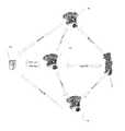
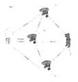
- FIG. 1is a functional block diagram of an exemplary system for performing a PTZ handoff in accordance with an embodiment of the present invention
- FIG. 2Arepresents an image plane according to an embodiment of the present invention
- FIG. 2Brepresents an imagine plane in context with the world plane
- FIG. 3A-3Crepresent the 3D positions of objects at three consecutive points in time.
- Embodiments of the present inventionprovide at least the following capabilities: 1) active collaborative tracking of multiple targets over a wide area; 2) Passive tracking based on external 2D/3D track data; 3) Visual assessment; 4) Video & track based object designation; 5) Output 2D and 3D tracks for all observed objects.
- the systemincludes manager component 110 which is capable of receiving visual data regarding an at least one object to be tracked and sending at least one control signal to a series of visual sensing units to track the at least one object 115 .
- the system according to embodiments of the present inventionalso includes visual sensing unit in a master mode 120 associated with the manager component 110 and capable of receiving visual data, transmitting the visual data to the manager component 110 regarding the position of the at least one object 115 to be tracked, receiving the at least one control signal from the manager component 110 for tracking the at least one object 115 , and transmitting the at least one control signal to a visual sensing unit in a slave mode 130 .
- the systemincludes at least one visual sensing unit in a slave mode 130 associated with the visual sensing unit in a master mode 120 and the manager component 110 and capable of receiving visual data regarding the location of the at least one object 115 , transmitting the visual data to the manager component 110 regarding the location of the at least one object 115 to be tracked, and receiving the at least one control signal from the visual sensing unit in the master mode 120 for tracking the at least one object 115 .
- the manager componentis, but is not limited to, a server. In further embodiments according to the present invention, the manager component is, but is not limited to, a computer. In further embodiments according to the present invention, the manager component is, but is not limited to, a computer program. In further embodiments according to the present invention, the manager component is, but is not limited to, an algorithm. In further embodiments according to the present invention, the manager component is, but is not limited to, a list of instructions that implicitly implement an algorithm.
- Embodiments of the present inventioninclude a plurality of PTZ cameras in the master mode 120 and a plurality of PTZ cameras in the slave mode 130 .
- PTZ cameras in the master mode 120share a field of view with other PTZ cameras in the master mode 120 .
- PTZ cameras in the master mode 120share a field of view with PTZ cameras in the slave mode 130 .
- PTZ cameras in the slave mode 130share a field of view with other PTZ cameras in the slave mode 130 .
- PTZ cameras in the slave mode 130share a field of view with other PTZ cameras in the slave mode 130 .
- the PTZ cameras in the master mode 120 and the PTZ cameras in the slave mode 130produce video output streams that consists of the video taken of the field of view of the PTZ cameras in the master mode 120 and the PTZ cameras in the slave mode 130 . Further, in embodiments of the present invention the PTZ cameras in the master mode 120 and the PTZ cameras in the slave mode 130 receive control signals as input that control the pan, tilt and zoom values for the PTZ cameras in the master mode 120 and the PTZ cameras in the slave mode 130 .
- the PTZ cameras in master mode 120 and the PTZ cameras in the slave mode 130each contain a tracker component which assigns identification information to each object within its field of view.
- the identification informationmay include, but is not limited to, the position, size, shape, velocity and acceleration of the object.
- the position of an objectis described in terms of the position of its centroid in the image.
- centroidis known to those of skill in the art.
- shape of the objectis denoted using a gaussian model. Guassian models are known to those of skill in the art.
- the identification information for each objectis preserved over all the images for a given camera.
- the PTZ manager 110receives a set of objects detected by the PTZ cameras in the master mode 120 and the PTZ cameras in the slave mode 130 as input.
- the functionality of the PTZ manager 110is to control the PTZ cameras in the master mode 120 and the PTZ cameras in the slave mode 130 such that the field of view of the each of the PTZ cameras in the master mode 120 and the PTZ cameras in the slave mode 130 always keeps a designated object at the center.
- the amount of pan or tilt required to accomplish thisis computed based on the position of the object.
- the zoomis decided based on the size of the object.
- the identification information about the object being followedis passed from the PTZ manager 110 to the PTZ cameras in the master mode 120 and the PTZ cameras in the slave mode 130 that have a field of view overlapping with the PTZ camera in the master mode 120 or the PTZ camera in the slave mode 130 that sent input to the PTZ manager 110 regarding the object's location.
- the PTZ manager 110also keeps a track of current pose information of the PTZ cameras in the master mode 120 and the PTZ cameras in the slave mode 130 that it is controlling. Using the pose information, the PTZ manager 110 computes the 3D position of all the objects it receives as input. It passes these 3D positions to the PTZ cameras in the master mode 120 and the PTZ cameras in the slave mode 130 that have a field of view overlapping with the PTZ camera in the master mode 120 or the PTZ camera in the slave mode 130 that sent input to the PTZ manager 110 regarding the object's location.
- one function of the PTZ manager 110is to keep the object being followed in the center of the field of view of the PTZ cameras in the master mode 120 and the PTZ cameras in the slave mode 130 .
- the amount of pan, tilt and zoom required to accomplish thisis computed by projecting the 3D position of the designated object onto the image captured by the PTZ cameras in the master mode 120 and the PTZ cameras in the slave mode 130 using the current pose information of the PTZ cameras in the master mode 120 and the PTZ cameras in the slave mode 130 .
- an initial stepis to estimate the position of the foot of the object.
- footis known to those of skill in the art. This may be performed by projecting the centroid of the object onto the base of the bounding box of the object, which in turn is computed using the gaussian.
- gaussianis known to those of skill in the art.
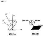
- FIG. 2Arepresents the image plane, which is understood by those of skill in the art.
- the center dot 210denotes the centroid of the object.
- the oval 220denotes the gaussian.
- the dotted rectangle 230denotes the bounding box and the dot 240 outside of the oval and within the dotted rectangle 230 denotes the foot position that is used for computing the 3D position of the object in the world plane.
- FIG. 2Bdepicts the image plane in context with the world plane, which is understood by those of skill in the art.
- the PTZ manager 110keeps track of the current state of all the PTZ cameras.
- the state of a given PTZ cameraincludes, but is not limited to, the PTZ camera's location, pose, and field of view.
- a PTZ camera's poseincludes, but is not limited to, the direction it is facing and the orientation of its pan, tilt and zoom features.
- Any PTZ camera in the master mode 120 that wants to acquire ownership of a PTZ Camera in the slave mode 130must first take permission from the PTZ manager 110 in order to do so.
- the PTZ manager 110maintains ownership information for each PTZ Camera.
- Each PTZ camera in the master mode 120owns a given PTZ camera in the slave mode 130 for a given time duration.
- the function of the PTZ manager 110is to give ownership of a PTZ camera in the slave mode 130 to a new PTZ camera in the master mode 120 if a PTZ camera in the master mode 120 requests it or if no PTZ camera in the master mode 120 currently owns it.
- the PTZ manager 110receives the 3D position of all the objects being detected by all the PTZ cameras in the system. It also has knowledge about which PTZ cameras have overlapping fields of view. This module also has the zone mask images, which are known to those of skill in the art, of each of the PTZ cameras, and which can be used to determine whether a given 3D position in the world can be viewed from a given PTZ camera.
- a function of the PTZ manager 110is to assign PTZ cameras in the slave mode 130 to those PTZ cameras that are in master mode 120 . Also, in embodiments of the present invention the PTZ manager 110 is able to make associations among the objects being tracked so once an object moves out of the visibility of a PTZ camera in the master mode 120 , the PTZ manager can then assign one of the PTZ cameras in the slave mode 130 to become a PTZ camera in the master mode 120 and continue to following the object.
- the PTZ manager 110maintains data regarding the 3D position of the object that a given PTZ in the master mode 120 is following.
- the PTZ manager 110generates a list of PTZ cameras in the slave mode 136 that have their field of view overlapping with the PTZ camera in the master mode 120 .
- Those PTZ cameras in the slave mode 130 that are assigned to the PTZ camera in the master mode 120are those that have an overlapping field of view with the PTZ camera in the master mode 130 , can see the current 3D position of the object being tracked, and are free to be assigned to a PTZ camera in the master mode 120 other than the one to which they are currently assigned.
- the decision about visibility of the 3D position of the object by a PTZ in the slave mode 130is made using the zone mask image of the PTZ in the slave mode 130 .
- PTZ cameras in the master mode 120may query the PTZ manager 110 to determine whether a PTZ camera in the slave mode 130 is available.
- a PTZ camera in the slave mode 130is available, for example, if it is not committed to following another object at the time that a PTZ camera in the master mode 120 requests it.
- voteswhich are known to those of skill in the art, are cast by all the objects detected by PTZ cameras in the slave mode 130 .
- the votes of only those objectsare counted whose 3D position are within a pre-decided radius of the 3D position of the object being tracked by the PTZ camera in the master mode 120 .
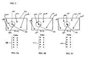
- FIG. 3A-3Cthe 3D positions of objects are shown at three consecutive points of time.
- the outer rectangle 310denotes the world plane.
- the square 320denotes the 3D position of the object being followed by the PTZ camera in the master mode 120 .
- the solid-line circles 330 a, 330 b , 330 c , 330 d and 330 edenote the objects being detected by one of the PTZ cameras in the slave mode 130 .
- the voting field 340is shown corresponding to that frame.
- the dotted circledenotes the search radius 350 . Only those objects detected by the PTZ camera in the slave mode 120 that are within the search radius 350 , cast votes at any given frame.
- the list of PTZ cameras in the slave mode 130is updated based upon whether the new 3D position of the object being followed by the PTZ camera in the master mode 120 is still visible to each of the PTZ cameras in the slave mode 130 or not.
- objectsmay be assigned different levels of priority by the operator of the system.
- an intrusion along a wallmay be assigned a higher priority than in intrusion at a main gate where, perhaps, there are guards or other protective measures in place.
- the PTZ manager 110may have given ownership of a PTZ camera in the slave mode 130 which is on the list of PTZ cameras in the slave mode 130 to a PTZ camera in the master mode 120 which is tracking an object with a higher priority.
- a new list of PTZ cameras in the slave mode 130is generated which takes into account that this PTZ camera in the slave mode 130 has been assigned to a PTZ camera in the master mode 120 which is tracking an object with a higher priority.
- one of PTZ cameras in the slave mode 130is designated by the PTZ manager 110 as a PTZ camera in the master mode 120 .
- the PTZ manager 110makes the determination regarding which PTZ camera in the slave mode 130 is to be designated a PTZ camera in the master mode 120 based on the number of votes associated with each of the PTZ cameras in the slave mode 130 .
Landscapes
- Physics & Mathematics (AREA)
- Engineering & Computer Science (AREA)
- Electromagnetism (AREA)
- General Physics & Mathematics (AREA)
- Radar, Positioning & Navigation (AREA)
- Remote Sensing (AREA)
- Multimedia (AREA)
- Signal Processing (AREA)
- Closed-Circuit Television Systems (AREA)
- Image Analysis (AREA)
- Studio Devices (AREA)
Abstract
Description
- 2D position in of the image of the object (centroid of the object)( i.e., the x, y coordinates));
- Gaussian denoting the shape of the object;
- Pose information of the camera i.e. P (3×4 Matrix); and
- The Equation of the World Plane i.e. Ax+By+Cz+D=O
Claims (17)
Priority Applications (1)
| Application Number | Priority Date | Filing Date | Title |
|---|---|---|---|
| US11/524,134US8310554B2 (en) | 2005-09-20 | 2006-09-20 | Method and apparatus for performing coordinated multi-PTZ camera tracking |
Applications Claiming Priority (2)
| Application Number | Priority Date | Filing Date | Title |
|---|---|---|---|
| US71863705P | 2005-09-20 | 2005-09-20 | |
| US11/524,134US8310554B2 (en) | 2005-09-20 | 2006-09-20 | Method and apparatus for performing coordinated multi-PTZ camera tracking |
Publications (2)
| Publication Number | Publication Date |
|---|---|
| US20070064107A1 US20070064107A1 (en) | 2007-03-22 |
| US8310554B2true US8310554B2 (en) | 2012-11-13 |
Family
ID=37883647
Family Applications (1)
| Application Number | Title | Priority Date | Filing Date |
|---|---|---|---|
| US11/524,134Active2030-07-02US8310554B2 (en) | 2005-09-20 | 2006-09-20 | Method and apparatus for performing coordinated multi-PTZ camera tracking |
Country Status (1)
| Country | Link |
|---|---|
| US (1) | US8310554B2 (en) |
Cited By (30)
| Publication number | Priority date | Publication date | Assignee | Title |
|---|---|---|---|---|
| US20110022972A1 (en)* | 2009-07-24 | 2011-01-27 | Raytheon Company | Method and System for Facilitating Interactive Review of Data |
| US20120081520A1 (en)* | 2010-10-04 | 2012-04-05 | Samsung Electronics Co., Ltd. | Apparatus and method for attenuating stereoscopic sense of stereoscopic image |
| US20120307071A1 (en)* | 2011-05-30 | 2012-12-06 | Toshio Nishida | Monitoring camera system |
| US9001226B1 (en)* | 2012-12-04 | 2015-04-07 | Lytro, Inc. | Capturing and relighting images using multiple devices |
| CN103826103B (en)* | 2014-02-27 | 2017-03-22 | 浙江宇视科技有限公司 | Cruise control method for tripod head video camera |
| US10205896B2 (en) | 2015-07-24 | 2019-02-12 | Google Llc | Automatic lens flare detection and correction for light-field images |
| US10275892B2 (en) | 2016-06-09 | 2019-04-30 | Google Llc | Multi-view scene segmentation and propagation |
| US10275898B1 (en) | 2015-04-15 | 2019-04-30 | Google Llc | Wedge-based light-field video capture |
| US10298834B2 (en) | 2006-12-01 | 2019-05-21 | Google Llc | Video refocusing |
| US10334151B2 (en) | 2013-04-22 | 2019-06-25 | Google Llc | Phase detection autofocus using subaperture images |
| US10341632B2 (en) | 2015-04-15 | 2019-07-02 | Google Llc. | Spatial random access enabled video system with a three-dimensional viewing volume |
| US10354399B2 (en) | 2017-05-25 | 2019-07-16 | Google Llc | Multi-view back-projection to a light-field |
| US10412373B2 (en) | 2015-04-15 | 2019-09-10 | Google Llc | Image capture for virtual reality displays |
| US10419737B2 (en) | 2015-04-15 | 2019-09-17 | Google Llc | Data structures and delivery methods for expediting virtual reality playback |
| US10440407B2 (en) | 2017-05-09 | 2019-10-08 | Google Llc | Adaptive control for immersive experience delivery |
| US10444931B2 (en) | 2017-05-09 | 2019-10-15 | Google Llc | Vantage generation and interactive playback |
| US10469873B2 (en) | 2015-04-15 | 2019-11-05 | Google Llc | Encoding and decoding virtual reality video |
| US10474227B2 (en) | 2017-05-09 | 2019-11-12 | Google Llc | Generation of virtual reality with 6 degrees of freedom from limited viewer data |
| US10540818B2 (en) | 2015-04-15 | 2020-01-21 | Google Llc | Stereo image generation and interactive playback |
| US10545215B2 (en) | 2017-09-13 | 2020-01-28 | Google Llc | 4D camera tracking and optical stabilization |
| US10546424B2 (en) | 2015-04-15 | 2020-01-28 | Google Llc | Layered content delivery for virtual and augmented reality experiences |
| US10552947B2 (en) | 2012-06-26 | 2020-02-04 | Google Llc | Depth-based image blurring |
| US10565734B2 (en) | 2015-04-15 | 2020-02-18 | Google Llc | Video capture, processing, calibration, computational fiber artifact removal, and light-field pipeline |
| US10567464B2 (en) | 2015-04-15 | 2020-02-18 | Google Llc | Video compression with adaptive view-dependent lighting removal |
| US10594945B2 (en) | 2017-04-03 | 2020-03-17 | Google Llc | Generating dolly zoom effect using light field image data |
| US10679361B2 (en) | 2016-12-05 | 2020-06-09 | Google Llc | Multi-view rotoscope contour propagation |
| US10965862B2 (en) | 2018-01-18 | 2021-03-30 | Google Llc | Multi-camera navigation interface |
| US10972647B2 (en)* | 2018-02-09 | 2021-04-06 | Camera Control At A Distance, Llc | System to control camera function remotely |
| US10984238B2 (en)* | 2019-04-15 | 2021-04-20 | China University Of Petroleum (East China) | Semi-supervised automatic marking method and device for ground-object in hyperspectral image |
| US11328446B2 (en) | 2015-04-15 | 2022-05-10 | Google Llc | Combining light-field data with active depth data for depth map generation |
Families Citing this family (15)
| Publication number | Priority date | Publication date | Assignee | Title |
|---|---|---|---|---|
| GB2492247B (en)* | 2008-03-03 | 2013-04-10 | Videoiq Inc | Dynamic object classification |
| TWI492188B (en)* | 2008-12-25 | 2015-07-11 | Univ Nat Chiao Tung | Method for automatic detection and tracking of multiple targets with multiple cameras and system therefor |
| US8531525B2 (en)* | 2009-12-22 | 2013-09-10 | Utc Fire & Security Americas Corporation, Inc. | Surveillance system and method for operating same |
| US8704903B2 (en)* | 2009-12-29 | 2014-04-22 | Cognex Corporation | Distributed vision system with multi-phase synchronization |
| US20120033082A1 (en)* | 2010-08-06 | 2012-02-09 | D & S Consultants, Inc. | System and Method for Spatial Division Multiplexing Detection |
| US9171075B2 (en) | 2010-12-30 | 2015-10-27 | Pelco, Inc. | Searching recorded video |
| US9615064B2 (en)* | 2010-12-30 | 2017-04-04 | Pelco, Inc. | Tracking moving objects using a camera network |
| AU2011201953B2 (en)* | 2011-04-29 | 2013-09-19 | Canon Kabushiki Kaisha | Fault tolerant background modelling |
| US9210385B2 (en) | 2012-11-20 | 2015-12-08 | Pelco, Inc. | Method and system for metadata extraction from master-slave cameras tracking system |
| US9412048B2 (en) | 2014-04-21 | 2016-08-09 | Haier Us Appliance Solutions, Inc. | Systems and methods for cookware detection |
| US9449220B2 (en)* | 2014-04-21 | 2016-09-20 | Haier Us Appliance Solutions, Inc. | Systems and methods for cookware detection |
| US10785458B2 (en)* | 2017-03-24 | 2020-09-22 | Blackberry Limited | Method and system for distributed camera network |
| JP6872704B2 (en)* | 2017-09-14 | 2021-05-19 | パナソニックIpマネジメント株式会社 | Surveillance camera system and surveillance method |
| CN109922251B (en)* | 2017-12-12 | 2021-10-22 | 华为技术有限公司 | Method, device and system for rapid capture |
| JP6992536B2 (en)* | 2018-01-19 | 2022-01-13 | 富士通株式会社 | Observation system and observation method |
Citations (1)
| Publication number | Priority date | Publication date | Assignee | Title |
|---|---|---|---|---|
| US20050134685A1 (en)* | 2003-12-22 | 2005-06-23 | Objectvideo, Inc. | Master-slave automated video-based surveillance system |
- 2006
- 2006-09-20USUS11/524,134patent/US8310554B2/enactiveActive
Patent Citations (1)
| Publication number | Priority date | Publication date | Assignee | Title |
|---|---|---|---|---|
| US20050134685A1 (en)* | 2003-12-22 | 2005-06-23 | Objectvideo, Inc. | Master-slave automated video-based surveillance system |
Cited By (32)
| Publication number | Priority date | Publication date | Assignee | Title |
|---|---|---|---|---|
| US10298834B2 (en) | 2006-12-01 | 2019-05-21 | Google Llc | Video refocusing |
| US10248697B2 (en)* | 2009-07-24 | 2019-04-02 | Raytheon Company | Method and system for facilitating interactive review of data |
| US20110022972A1 (en)* | 2009-07-24 | 2011-01-27 | Raytheon Company | Method and System for Facilitating Interactive Review of Data |
| US20120081520A1 (en)* | 2010-10-04 | 2012-04-05 | Samsung Electronics Co., Ltd. | Apparatus and method for attenuating stereoscopic sense of stereoscopic image |
| US9225960B2 (en)* | 2010-10-04 | 2015-12-29 | Samsung Electronics Co., Ltd. | Apparatus and method for attenuating stereoscopic sense of stereoscopic image |
| US20120307071A1 (en)* | 2011-05-30 | 2012-12-06 | Toshio Nishida | Monitoring camera system |
| US10552947B2 (en) | 2012-06-26 | 2020-02-04 | Google Llc | Depth-based image blurring |
| US9001226B1 (en)* | 2012-12-04 | 2015-04-07 | Lytro, Inc. | Capturing and relighting images using multiple devices |
| US10334151B2 (en) | 2013-04-22 | 2019-06-25 | Google Llc | Phase detection autofocus using subaperture images |
| CN103826103B (en)* | 2014-02-27 | 2017-03-22 | 浙江宇视科技有限公司 | Cruise control method for tripod head video camera |
| US10275898B1 (en) | 2015-04-15 | 2019-04-30 | Google Llc | Wedge-based light-field video capture |
| US10341632B2 (en) | 2015-04-15 | 2019-07-02 | Google Llc. | Spatial random access enabled video system with a three-dimensional viewing volume |
| US11328446B2 (en) | 2015-04-15 | 2022-05-10 | Google Llc | Combining light-field data with active depth data for depth map generation |
| US10412373B2 (en) | 2015-04-15 | 2019-09-10 | Google Llc | Image capture for virtual reality displays |
| US10419737B2 (en) | 2015-04-15 | 2019-09-17 | Google Llc | Data structures and delivery methods for expediting virtual reality playback |
| US10567464B2 (en) | 2015-04-15 | 2020-02-18 | Google Llc | Video compression with adaptive view-dependent lighting removal |
| US10565734B2 (en) | 2015-04-15 | 2020-02-18 | Google Llc | Video capture, processing, calibration, computational fiber artifact removal, and light-field pipeline |
| US10469873B2 (en) | 2015-04-15 | 2019-11-05 | Google Llc | Encoding and decoding virtual reality video |
| US10546424B2 (en) | 2015-04-15 | 2020-01-28 | Google Llc | Layered content delivery for virtual and augmented reality experiences |
| US10540818B2 (en) | 2015-04-15 | 2020-01-21 | Google Llc | Stereo image generation and interactive playback |
| US10205896B2 (en) | 2015-07-24 | 2019-02-12 | Google Llc | Automatic lens flare detection and correction for light-field images |
| US10275892B2 (en) | 2016-06-09 | 2019-04-30 | Google Llc | Multi-view scene segmentation and propagation |
| US10679361B2 (en) | 2016-12-05 | 2020-06-09 | Google Llc | Multi-view rotoscope contour propagation |
| US10594945B2 (en) | 2017-04-03 | 2020-03-17 | Google Llc | Generating dolly zoom effect using light field image data |
| US10474227B2 (en) | 2017-05-09 | 2019-11-12 | Google Llc | Generation of virtual reality with 6 degrees of freedom from limited viewer data |
| US10444931B2 (en) | 2017-05-09 | 2019-10-15 | Google Llc | Vantage generation and interactive playback |
| US10440407B2 (en) | 2017-05-09 | 2019-10-08 | Google Llc | Adaptive control for immersive experience delivery |
| US10354399B2 (en) | 2017-05-25 | 2019-07-16 | Google Llc | Multi-view back-projection to a light-field |
| US10545215B2 (en) | 2017-09-13 | 2020-01-28 | Google Llc | 4D camera tracking and optical stabilization |
| US10965862B2 (en) | 2018-01-18 | 2021-03-30 | Google Llc | Multi-camera navigation interface |
| US10972647B2 (en)* | 2018-02-09 | 2021-04-06 | Camera Control At A Distance, Llc | System to control camera function remotely |
| US10984238B2 (en)* | 2019-04-15 | 2021-04-20 | China University Of Petroleum (East China) | Semi-supervised automatic marking method and device for ground-object in hyperspectral image |
Also Published As
| Publication number | Publication date |
|---|---|
| US20070064107A1 (en) | 2007-03-22 |
Similar Documents
| Publication | Publication Date | Title |
|---|---|---|
| US8310554B2 (en) | Method and apparatus for performing coordinated multi-PTZ camera tracking | |
| US12333922B2 (en) | Integrative security system and method | |
| US8854469B2 (en) | Method and apparatus for tracking persons and locations using multiple cameras | |
| US20070008408A1 (en) | Wide area security system and method | |
| US9520040B2 (en) | System and method for real-time 3-D object tracking and alerting via networked sensors | |
| JP4617269B2 (en) | Monitoring system | |
| US20160019427A1 (en) | Video surveillence system for detecting firearms | |
| CN108550234B (en) | Label matching and fence boundary management method and device for double base stations and storage medium | |
| US9767663B2 (en) | GPS directed intrusion system with data acquisition | |
| US20110115909A1 (en) | Method for tracking an object through an environment across multiple cameras | |
| MXPA04003441A (en) | Video tripwire. | |
| RU2268497C2 (en) | System and method for automated video surveillance and recognition of objects and situations | |
| US20200336708A1 (en) | Duplicate monitored area prevention | |
| KR101290782B1 (en) | System and method for Multiple PTZ Camera Control Based on Intelligent Multi-Object Tracking Algorithm | |
| US20220120607A1 (en) | Optical fiber sensing system, monitoring apparatus, monitoring method, and computer readable medium | |
| CN110807345B (en) | Building evacuation method and building evacuation system | |
| CN112818780A (en) | Defense area setting method and device for aircraft monitoring and identifying system | |
| WO2020246251A1 (en) | Information processing device, method, and program | |
| Purohit et al. | Real-Time Threat Detection and Response Using Computer Vision in Border Security | |
| CN113012199B (en) | Systems and methods for moving target tracking | |
| Chakravarty et al. | Anomaly detection and tracking for a patrolling robot | |
| US11070770B2 (en) | Method and system for auto-calibration of multiple sensors for event tracking | |
| KR20220154473A (en) | System of peventing external intrusion using virtulal detection line in image | |
| KR20180058331A (en) | Security apparatus and method using drone | |
| US20250068730A1 (en) | Methods for handling a potential adversarial attack on an autonomous vehicle while driving a road |
Legal Events
| Date | Code | Title | Description |
|---|---|---|---|
| AS | Assignment | Owner name:SAMOFF CORPORATION, NEW JERSEY Free format text:ASSIGNMENT OF ASSIGNORS INTEREST;ASSIGNORS:AGGARWAL, MANOJ;SETHI, DEEPAK;SAMARASEKERA, SUPUN;AND OTHERS;SIGNING DATES FROM 20061020 TO 20061030;REEL/FRAME:018526/0424 Owner name:SAMOFF CORPORATION, NEW JERSEY Free format text:ASSIGNMENT OF ASSIGNORS INTEREST;ASSIGNORS:AGGARWAL, MANOJ;SETHI, DEEPAK;SAMARASEKERA, SUPUN;AND OTHERS;REEL/FRAME:018526/0424;SIGNING DATES FROM 20061020 TO 20061030 | |
| AS | Assignment | Owner name:SARNOFF CORPORATION, NEW JERSEY Free format text:CORRECTIVE ASSIGNMENT TO CORRECT THE ASSIGNEE'S NAME PREVIOUSLY RECORDED ON REEL 018526 FRAME 0424;ASSIGNORS:AGGARWAL, MANOJ;SETHI, DEEPAK;SAMARASEKERA, SUPUN;AND OTHERS;REEL/FRAME:018579/0545;SIGNING DATES FROM 20061020 TO 20061030 Owner name:SARNOFF CORPORATION, NEW JERSEY Free format text:CORRECTIVE ASSIGNMENT TO CORRECT THE ASSIGNEE'S NAME PREVIOUSLY RECORDED ON REEL 018526 FRAME 0424. ASSIGNOR(S) HEREBY CONFIRMS THE CORRECT ASSIGNEE NAME;ASSIGNORS:AGGARWAL, MANOJ;SETHI, DEEPAK;SAMARASEKERA, SUPUN;AND OTHERS;SIGNING DATES FROM 20061020 TO 20061030;REEL/FRAME:018579/0545 | |
| AS | Assignment | Owner name:SRI INTERNATIONAL, CALIFORNIA Free format text:MERGER;ASSIGNOR:SARNOFF CORPORATION;REEL/FRAME:026753/0884 Effective date:20110204 | |
| FEPP | Fee payment procedure | Free format text:PAYOR NUMBER ASSIGNED (ORIGINAL EVENT CODE: ASPN); ENTITY STATUS OF PATENT OWNER: SMALL ENTITY | |
| AS | Assignment | Owner name:SRI INTERNATIONAL, CALIFORNIA Free format text:MERGER;ASSIGNOR:SARNOFF CORPORATION;REEL/FRAME:029042/0066 Effective date:20110204 | |
| STCF | Information on status: patent grant | Free format text:PATENTED CASE | |
| FPAY | Fee payment | Year of fee payment:4 | |
| MAFP | Maintenance fee payment | Free format text:PAYMENT OF MAINTENANCE FEE, 8TH YR, SMALL ENTITY (ORIGINAL EVENT CODE: M2552); ENTITY STATUS OF PATENT OWNER: SMALL ENTITY Year of fee payment:8 | |
| MAFP | Maintenance fee payment | Free format text:PAYMENT OF MAINTENANCE FEE, 12TH YR, SMALL ENTITY (ORIGINAL EVENT CODE: M2553); ENTITY STATUS OF PATENT OWNER: SMALL ENTITY Year of fee payment:12 |