US8310458B2 - Electronic device including a moveable touch-sensitive input and method of controlling same - Google Patents
Electronic device including a moveable touch-sensitive input and method of controlling sameDownload PDFInfo
- Publication number
- US8310458B2 US8310458B2US12/497,724US49772409AUS8310458B2US 8310458 B2US8310458 B2US 8310458B2US 49772409 AUS49772409 AUS 49772409AUS 8310458 B2US8310458 B2US 8310458B2
- Authority
- US
- United States
- Prior art keywords
- touch
- sensitive input
- electronic device
- input assembly
- base
- Prior art date
- Legal status (The legal status is an assumption and is not a legal conclusion. Google has not performed a legal analysis and makes no representation as to the accuracy of the status listed.)
- Active, expires
Links
Images


Classifications
- G—PHYSICS
- G06—COMPUTING OR CALCULATING; COUNTING
- G06F—ELECTRIC DIGITAL DATA PROCESSING
- G06F3/00—Input arrangements for transferring data to be processed into a form capable of being handled by the computer; Output arrangements for transferring data from processing unit to output unit, e.g. interface arrangements
- G06F3/01—Input arrangements or combined input and output arrangements for interaction between user and computer
- G06F3/016—Input arrangements with force or tactile feedback as computer generated output to the user
- G—PHYSICS
- G06—COMPUTING OR CALCULATING; COUNTING
- G06F—ELECTRIC DIGITAL DATA PROCESSING
- G06F3/00—Input arrangements for transferring data to be processed into a form capable of being handled by the computer; Output arrangements for transferring data from processing unit to output unit, e.g. interface arrangements
- G06F3/01—Input arrangements or combined input and output arrangements for interaction between user and computer
- G06F3/03—Arrangements for converting the position or the displacement of a member into a coded form
- G06F3/041—Digitisers, e.g. for touch screens or touch pads, characterised by the transducing means
- G06F3/044—Digitisers, e.g. for touch screens or touch pads, characterised by the transducing means by capacitive means
- H—ELECTRICITY
- H04—ELECTRIC COMMUNICATION TECHNIQUE
- H04M—TELEPHONIC COMMUNICATION
- H04M2250/00—Details of telephonic subscriber devices
- H04M2250/12—Details of telephonic subscriber devices including a sensor for measuring a physical value, e.g. temperature or motion
- H—ELECTRICITY
- H04—ELECTRIC COMMUNICATION TECHNIQUE
- H04M—TELEPHONIC COMMUNICATION
- H04M2250/00—Details of telephonic subscriber devices
- H04M2250/22—Details of telephonic subscriber devices including a touch pad, a touch sensor or a touch detector
Definitions
- the present disclosurerelates to portable electronic devices that include a touch-sensitive input device such as a touch-sensitive display and the provision of tactile feedback and the generation of sound using such input devices.
- Portable electronic deviceshave gained widespread use and may provide a variety of functions including, for example, telephonic, electronic messaging and other personal information manager (PIM) application functions.
- Portable electronic devicescan include several types of devices including mobile stations such as simple cellular telephones, smart telephones, wireless PDAs, and laptop computers with wireless 802.11 or Bluetooth capabilities. Touch-sensitive input devices are useful for input on a portable electronic device.
- Touch screen devicesconstructed of a display, such as a liquid crystal display, with a touch-sensitive overlay are useful on such handheld devices as such handheld devices are small and are therefore limited in space available for user input and output devices. Further, the screen content on the touch screen devices can be modified depending on the functions and operations being performed.
- FIG. 1is a simplified block diagram of components including internal components of a portable electronic device according an aspect of an embodiment
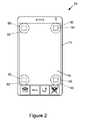
- FIG. 2is a front view of an example of a portable electronic device in a portrait orientation
- FIG. 3Ais a sectional side view of portions of the touch-sensitive input assembly of FIG. 2 ;
- FIG. 3Bis a sectional side view of portions of the touch-sensitive input assembly of FIG. 2 ;
- FIG. 3Cis a side view of a portion of the portable electronic device of FIG. 2 according to one embodiment
- FIG. 4is a functional block diagram of an actuating arrangement of the portable electronic device
- FIG. 5is a flow-chart illustrating a method of controlling a portable electronic device according to an embodiment
- FIG. 6is a flow chart illustrating another method of controlling the portable electronic device according to an embodiment.
- the disclosuregenerally relates to an electronic device, which in the embodiments described herein is a portable electronic device.
- portable electronic devicesinclude mobile, or handheld, wireless communication devices such as pagers, cellular phones, cellular smart-phones, wireless organizers, personal digital assistants, wirelessly enabled notebook computers and the like.
- the portable electronic devicemay be a two-way communication device with advanced data communication capabilities including the capability to communicate with other portable electronic devices or computer systems through a network of transceiver stations.
- the portable electronic devicemay also have the capability to allow voice communication.
- itmay be referred to as a data messaging device, a two-way pager, a cellular telephone with data messaging capabilities, a wireless Internet appliance, or a data communication device (with or without telephony capabilities).
- the portable electronic devicemay also be a portable device without wireless communication capabilities as a handheld electronic game device, digital photograph album, digital camera and the like.
- the portable electronic device 20includes a number of components such as the processor 22 that controls the overall operation of the portable electronic device 20 . Communication functions, including data and voice communications, are performed through a communication subsystem 24 . Data received by the portable electronic device 20 may be decompressed and decrypted by a decoder 26 , operating according to any suitable decompression techniques (e.g. YK decompression, and other known techniques) and encryption techniques (e.g. using an encryption technique such as Data Encryption Standard (DES), Triple DES, or Advanced Encryption Standard (AES)).
- DESData Encryption Standard
- Triple DESTriple DES
- AESAdvanced Encryption Standard
- the communication subsystem 24receives messages from and sends messages to a wireless network 1000 .
- the communication subsystem 24is configured in accordance with the Global System for Mobile Communication (GSM) and General Packet Radio Services (GPRS) standards.
- GSMGlobal System for Mobile Communication
- GPRSGeneral Packet Radio Services
- the GSM/GPRS wireless networkis used worldwide and it is expected that these standards will be superseded eventually by Enhanced Data GSM Environment (EDGE) and Universal Mobile Telecommunications Service (UMTS). New standards are still being defined, but it is believed that they will have similarities to the network behavior described herein, and it will also be understood by persons skilled in the art that the embodiments described herein are intended to use any other suitable standards that are developed in the future.
- the wireless link connecting the communication subsystem 24 with the wireless network 1000represents one or more different Radio Frequency (RF) channels, operating according to defined protocols specified for GSM/GPRS communications. With newer network protocols, these channels are capable of supporting both circuit switched voice communications and packet switched data communications.
- RFRadio Frequency
- wireless network 1000 associated with the portable electronic device 20is a GSM/GPRS wireless network in one example of an implementation
- other wireless networksmay also be associated with the portable electronic device 20 in variant implementations.
- the different types of wireless networks that may be employedinclude, for example, data-centric wireless networks, voice-centric wireless networks, and dual-mode networks that support both voice and data communications over the same physical base stations.
- Combined dual-mode networksinclude, but are not limited to, Code Division Multiple Access (CDMA) or CDMA2000 networks, GSM/GPRS networks (as mentioned above), and future third-generation (3G) networks like EDGE and UMTS.
- Some other examples of data-centric networksinclude WiFi 802.11, MobitexTM and DataTACTM network communication systems.
- Examples of other voice-centric data networksinclude Personal Communication Systems (PCS) networks like GSM and Time Division Multiple Access (TDMA) systems.
- PCSPersonal Communication Systems
- TDMATime Division Multiple Access
- the processor 22also interacts with additional subsystems such as a Random Access Memory (RAM) 28 , a flash memory 30 , a display 32 with a touch-sensitive overlay 34 connected to an electronic controller 36 that together are part of a touch-sensitive input assembly 38 , an auxiliary input/output (I/O) subsystem 40 , an accelerometer 41 a data port 42 , a speaker 44 , a microphone 46 , short-range communications 48 and other device subsystems 50 .
- the touch-sensitive overlay 34 and the electronic controller 36provide a touch-sensitive input device and the processor 22 interacts with the touch-sensitive overlay 34 via the electronic controller 36 .
- An actuating arrangement 39is connected to and communicates with the processor 22 .
- the accelerometer 41may be a three-axis accelerometer and is used for detecting direction of gravitational forces (or gravity-induced reaction forces). Movement of the portable electronic device 20 to alternate orientations is detected and the orientation of the accelerometer 41 , and therefore of the portable electronic device 20 , may be determined.
- the display 32 and the touch-sensitive overlay 34may be used for both communication-related functions, such as entering a text message for transmission over the network 1000 , and device-resident functions such as a calculator or task list.
- the portable electronic device 20may send and receive communication signals over the wireless network 1000 after network registration or activation procedures have been completed. Network access is associated with a subscriber or user of the portable electronic device 20 .
- the portable electronic device 20uses a SIM/RUIM card 52 (i.e. Subscriber Identity Module or a Removable User Identity Module) inserted into a SIM/RUIM interface 54 for communication with a network such as the network 1000 .
- SIM/RUIM card 52is one type of a conventional “smart card” that may be used to identify a subscriber of the portable electronic device 20 and to personalize the portable electronic device 20 , among other things.
- the portable electronic device 20is not fully operational for communication with the wireless network 1000 without the SIM/RUIM card 52 .
- a subscribermay access all subscribed services. Services may include: web browsing and messaging such as e-mail, voice mail, Short Message Service (SMS), and Multimedia Messaging Services (MMS). More advanced services may include: point of sale, field service and sales force automation.
- the SIM/RUIM card 52includes a processor and memory for storing information. Once the SIM/RUIM card 52 is inserted into the SIM/RUIM interface 54 , it is coupled to the processor 22 .
- the SIM/RUIM card 52may include some user parameters such as an International Mobile Subscriber Identity (IMSI).
- IMSIInternational Mobile Subscriber Identity
- An advantage of using the SIM/RUIM card 52is that a subscriber is not necessarily bound by any single physical portable electronic device.
- the SIM/RUIM card 52may store additional subscriber information for a portable electronic device as well, including datebook (or calendar) information and recent call information. Alternatively, user identification information may also be programmed into the flash memory 30 .
- the portable electronic device 20is a battery-powered device and includes a battery interface 56 for receiving one or more rechargeable batteries 58 .
- the battery 58may be a smart battery with an embedded microprocessor.
- the battery interface 56is coupled to a regulator (not shown), which assists the battery 58 in providing power V+ to the portable electronic device 20 .
- a regulatornot shown
- future technologiessuch as micro fuel cells may provide the power to the portable electronic device 20 .
- the portable electronic device 20also includes an operating system 60 and software components 62 which are described in more detail below.
- the operating system 60 and the software components 62 that are executed by the processor 22are typically stored in a persistent store such as the flash memory 30 , which may alternatively be a read-only memory (ROM) or similar non-transitory storage element (not shown).
- a persistent storesuch as the flash memory 30
- ROMread-only memory
- portions of the operating system 60 and the software components 62such as specific software applications 64 , 66 , 68 , 70 and 72 , or parts thereof, may be temporarily loaded into a volatile store such as the RAM 28 .
- Other software componentsmay also be included, as is well known to those skilled in the art.
- the subset of software components 62 that control basic device operations, including data and voice communication applications,will normally be installed on the portable electronic device 20 during manufacture of the portable electronic device 20 .
- Other software applicationsinclude a message application 64 that may be any suitable software program that allows a user of the portable electronic device 20 to send and receive electronic messages.
- Messages that have been sent or received by the userare typically stored in the flash memory 30 of the portable electronic device 20 or some other suitable storage element in the portable electronic device 20 .
- some of the sent and received messagesmay be stored remotely from the device 20 such as in a data store of an associated host system that the portable electronic device 20 communicates with.
- the software components 62may further include a device state module 66 , a Personal Information Manager (PIM) 68 , and other suitable modules (not shown).
- the device state module 66provides persistence, i.e. the device state module 66 ensures that important device data is stored in persistent memory, such as the flash memory 30 , so that the data is not lost when the portable electronic device 20 is turned off or loses power.
- the PIM 68includes functionality for organizing and managing data items of interest to the user, such as, but not limited to, e-mail, contacts, calendar events, voice mails, appointments, and task items.
- the PIM 68has the ability to send and receive data items via the wireless network 1000 .
- PIM data itemsmay be seamlessly integrated, synchronized, and updated via the wireless network 1000 with the portable electronic device subscriber's corresponding data items stored and/or associated with a host computer system. This functionality creates a mirrored host computer on the portable electronic device 20 with respect to such items. This may be particularly advantageous when the host computer system is the portable electronic device subscriber's office computer system.
- the software components 62also includes a connect module 70 , and an information technology (IT) policy module 72 .
- the connect module 70implements the communication protocols that are required for the portable electronic device 20 to communicate with the wireless infrastructure and any host system, such as an enterprise system, that the portable electronic device 20 is authorized to interface with.
- the connect module 70includes a set of APIs that may be integrated with the portable electronic device 20 to allow the portable electronic device 20 to use any number of services associated with the enterprise system.
- the connect module 70allows the portable electronic device 20 to establish an end-to-end secure, authenticated communication pipe with the host system.
- a subset of applications for which access is provided by the connect module 70may be used to pass IT policy commands from the host system to the portable electronic device 20 . This may be done in a wireless or wired manner. These instructions may then be passed to the IT policy module 72 to modify the configuration of the device 20 . Alternatively, in some cases, the IT policy update may also be done over a wired connection.
- software applicationsmay also be installed on the portable electronic device 20 .
- These software applicationsmay be third party applications, which are added after the manufacture of the portable electronic device 20 .
- third party applicationsinclude games, calculators, utilities, etc.
- the additional applicationsmay be loaded onto the portable electronic device 20 through at least one of the wireless network 1000 , the auxiliary I/O subsystem 40 , the data port 42 , the short-range communications subsystem 48 , or any other suitable device subsystem 50 .
- This flexibility in application installationincreases the functionality of the portable electronic device 20 and may provide enhanced on-device functions, communication-related functions, or both.
- secure communication applicationsmay enable electronic commerce functions and other such financial transactions to be performed using the portable electronic device 20 .
- the data port 42enables a subscriber to set preferences through an external device or software application and extends the capabilities of the portable electronic device 20 by providing for information or software downloads to the portable electronic device 20 other than through a wireless communication network.
- the alternate download pathmay, for example, be used to load an encryption key onto the portable electronic device 20 through a direct and thus reliable and trusted connection to provide secure device communication.
- the data port 42may be any suitable port that enables data communication between the portable electronic device 20 and another computing device.
- the data port 42may be a serial or a parallel port.
- the data port 42may be a USB port that includes data lines for data transfer and a supply line that may provide a charging current to charge the battery 58 of the portable electronic device 20 .
- the short-range communications subsystem 48provides for communication between the portable electronic device 20 and different systems or devices, without the use of the wireless network 1000 .
- the short-range communications subsystem 48may include an infrared device and associated circuits and components for short-range communication.
- Examples of short-range communication standardsinclude standards developed by the Infrared Data Association (IrDA), Bluetooth, and the 802.11 family of standards developed by IEEE.
- a received signalsuch as a text message, an e-mail message, or web page download is processed by the communication subsystem 24 and input to the processor 22 .
- the processor 22then processes the received signal for output to the display 32 or alternatively to the auxiliary I/O subsystem 40 .
- a subscribermay also compose data items, such as e-mail messages, for example, using the touch-sensitive overlay 34 on the display 32 that are part of the touch-sensitive input assembly 38 , and possibly the auxiliary I/O subsystem 40 .
- the auxiliary subsystem 40may include devices such as: a mouse, track ball, infrared fingerprint detector, or a roller wheel with dynamic button pressing capability.
- a composed itemmay be transmitted over the wireless network 1000 through the communication subsystem 24 .
- the overall operation of the portable electronic device 20is substantially similar, except that the received signals may be output to the speaker 44 , and signals for transmission are generated by the microphone 46 .
- Alternative voice or audio I/O subsystemssuch as a voice message recording subsystem, may also be implemented on the portable electronic device 20 .
- voice or audio signal outputmay be accomplished through the speaker 44
- the touch-sensitive input assembly 38may also be used to provide audio output, for example, for speakerphone or ringer functions.
- FIG. 2shows a front view of an example of a portable electronic device 20 in portrait orientation.
- the portable electronic device 20includes a housing 74 that houses the internal components that are shown in FIG. 1 and frames the touch-sensitive input assembly 38 such that the touch-sensitive input assembly 38 is exposed for user-interaction therewith when the portable electronic device 20 is in use.
- the touch-sensitive input assembly 38may include any suitable number of user-selectable features rendered thereon, for example, in the form of virtual buttons for user-selection of, for example, applications, options, or keys of a keyboard for user entry of data during operation of the portable electronic device 20 .
- the touch-sensitive input assembly 38may be, for example, a capacitive touch-sensitive display that includes the display 32 and the touch-sensitive overlay 34 .
- a capacitive touch-sensitive overlay 34includes a number of layers in a stack and is fixed to the display 32 via a suitable optically clear adhesive.
- the layersmay include, for example a substrate fixed to the LCD display 32 by a suitable adhesive, a ground shield layer, a barrier layer, a pair of capacitive touch sensor layers separated by a substrate or other barrier layer, and a cover layer fixed to the second capacitive touch sensor layer by a suitable adhesive.
- the capacitive touch sensor layersmay be any suitable material such as patterned indium tin oxide (ITO).
- the X and Y location of a touch eventare both determined with the X location determined by a signal generated as a result of capacitive coupling with one of the touch sensor layers and the Y location determined by the signal generated as a result of capacitive coupling with the other of the touch sensor layers.
- Each of the touch-sensor layersprovides a signal to the controller 36 as a result of capacitive coupling with a suitable object such as a finger of a user resulting in a change in the electric field of each of the touch sensor layers.
- the signalsrepresent the respective X and Y touch location values. It will be appreciated that other attributes of the user's touch on the touch-sensitive input assembly 38 may be determined. For example, the size and the shape of the touch on the touch-sensitive input assembly 38 may be determined in addition to the location (X and Y values) based on the signals received at the controller 36 from the touch sensor layers.
- a user's touch on the touch-sensitive input assembly 38is determined by determining the X and Y touch location and user-selected input is determined based on the X and Y touch location and the application executed by the processor 22 .
- a featuresuch as a virtual button displayed on the touch-sensitive input assembly 38 may be selected by matching the feature to the X and Y location of a touch event on the touch-sensitive input assembly 38 .
- a feature that is selected by the useris determined based on the X and Y touch location and the application.
- the housing 74may be any suitable housing for the internal components shown in FIG. 1 and for sealing with and facilitating movement of the touch-sensitive input assembly 38 .
- the housing 74 in the present exampleincludes a back 76 , a frame 78 , which frames the touch-sensitive input assembly 38 and sidewalls 80 that extend between and generally perpendicular to the back 76 and the frame 78 .
- a base 82is spaced from and is generally parallel to the back 76 .
- the base 82may be any suitable base and may include, for example, a printed circuit board or flex circuit board supported by a stiff support between the base 82 and the back 76 .
- the back 76includes a plate (not shown) that is releasably attached for insertion and removal of, for example, the battery 58 and the SIM/RUIM card 52 described above. It will be appreciated that the back 76 , the sidewalls 80 and the frame 78 may be injection molded, for example. In the example of the portable electronic device 20 shown in FIG. 2 , the frame 78 is generally rectangular with rounded corners although other shapes are possible.
- the display 32 and the touch-sensitive overlay 34may be supported on a support tray 84 of suitable material such as magnesium for providing mechanical support to the display 32 and touch-sensitive overlay 34 .
- a compliant gasket 86may be located around the perimeter of the frame 78 , between an upper portion of the support tray 84 and the frame 78 to provide a seal for protecting the components housed in the housing 74 of the portable electronic device 20 against liquid ingress or foreign material such as sand, dust and lint.
- a suitable material for the compliant gasket 86includes, for example, a silicone rubber for providing a seal between the touch-sensitive input assembly and the housing 74 , for shock absorption, vibration damping and suitable fatigue life.
- the touch-sensitive input assembly 38is sealed against the housing 74 to provide a sealed volume of space within the housing 74 .
- the touch-sensitive input assembly 38is also moveable within the housing 74 as the touch-sensitive input assembly 38 may be moved away from the base 82 , thereby compressing the compliant gasket 86 , for example and may be moved toward the base 82 , thereby compressing shock-absorbing elements 88 referred to below.
- FIGS. 3A and 3Bshow exaggerated movement of the touch-sensitive input assembly 38 with FIG. 3A showing the touch-sensitive input assembly 38 moved toward the base 82 and with FIG. 3B showing the touch-sensitive input assembly 38 with the actuating arrangement 39 actuated to push the touch-sensitive input assembly 38 away from the base 82 .
- the compliant gasket 86also acts as a speaker spider for providing a restoring force, or spring, so that the touch-sensitive input assembly 38 returns to the rest position after being moved by the actuating arrangement 39 in response to an input signal.
- the actuating arrangement 39includes four piezoelectric actuators 90 , with each piezoelectric actuator 90 supported on a respective support ring 91 .
- Each support ring 91extends from the base 82 toward the touch-sensitive input assembly 38 for supporting the respective piezoelectric actuator 90 while permitting flexing of the piezoelectric actuator 90 .
- each piezoelectric actuator 90includes a piezoelectric disk 92 such as a PZT ceramic disk adhered to a metal substrate 94 of larger diameter than the piezoelectric disk 92 for bending when the piezoelectric disk 92 contracts as a result of build up of charge at the piezoelectric disk 92 .
- Each piezoelectric actuator 90is supported on the respective support ring 91 on one side of the base 82 , proximal a respective corner of the housing 74 with the metal ring sized such that the edge of the metal substrate 94 contacts the support ring 91 for supporting the piezoelectric actuator 90 and permitting flexing of the piezoelectric actuator 90 .
- a plunger 88which in the present example is a cylinder of suitable material such as a hard rubber for mechanical coupling between the piezoelectric actuator 90 and the touch-sensitive input assembly 38 . Hard rubber is a suitable material to reduce chattering during rapid movement.
- the plunger 88is located between the piezoelectric actuator 90 and the support tray 84 and may be adhered to the support tray 84 for applying forces thereto.
- a respective force sensor 96is located between each shock-absorbing element 88 and the respective piezoelectric actuator 90 and each respective force sensor 96 is adhered to both the respective plunger 88 and the respective piezoelectric actuator 90 .
- a suitable force sensor 96includes, for example, a puck-shaped force sensing resistor for measuring applied force (or pressure). It will be appreciated that a force may be determined using a force sensing resistor as an increase in pressure on the force sensing resistor results in a decrease in resistance (or increase in conductance).
- each piezoelectric actuator 90is located between the base 82 and the support tray 84 and force is applied on each piezoelectric actuator 90 by the touch-sensitive input assembly 38 , in the direction of the base 82 , causing bending of the piezoelectric actuator 90 .
- the piezoelectric actuator 90undergoes slight bending.
- An external applied force in the form of a user pressing on the touch-sensitive input assembly 38 during a touch event, and without actuation of the piezoelectric actuator 90causes increased bending of the piezoelectric actuator 90 , as shown in FIG.
- the piezoelectric actuator 90applies a spring force against the touch-sensitive input assembly 38 .
- a reverse charge on the piezoelectric actuator 90may result in further bending of the piezoelectric actuator 90 as shown in FIG. 3A .
- the piezoelectric disk 92is charged, the piezoelectric disk 92 shrinks and causes the metal substrate 94 and piezoelectric disk 92 to apply a further force on the touch-sensitive input assembly 38 as the piezoelectric actuator 90 straightens, as shown in FIG. 3B .
- the support rings 91may be part of the base 82 or may be supported on the base 82 .
- Each piezoelectric actuator 90is located between the base 82 and the support tray 84 such that an external applied force on the touch-sensitive input assembly 38 resulting from a user pressing the touch-sensitive input assembly 38 may be measured by the force sensors 96 and such that the charging of the piezoelectric actuator 90 results in an applied force on the touch-sensitive input assembly 38 to cause movement of the touch-sensitive input assembly 38 , away from the base 82 .
- each piezoelectric actuator 90is in contact with the support tray 84 .
- depression of the touch-sensitive input assembly 38 by user application of a force theretois determined by a change in resistance at the force sensors 96 and causes further bending of the piezoelectric actuators 90 as shown in FIG. 3A .
- the charge on the piezoelectric actuator 90may be modulated to control the force applied by the piezoelectric actuator 90 on the support tray 84 and the resulting movement of the touch-sensitive input assembly 38 .
- the chargemay be modulated by modulating the applied voltage or current.
- a currentmay be applied to increase the charge on the piezoelectric actuator 90 to contract the piezoelectric disk 92 as described above, causing the metal substrate 94 and the piezoelectric disk 92 to straighten as referred to above.
- This chargetherefore results in the force on the touch-sensitive input assembly 38 for moving the touch-sensitive input assembly 38 away from the base 82 , as shown in FIG. 3B .
- the charge on the piezoelectric actuator 90may also be removed via a controlled discharge current causing the piezoelectric disk 92 to expand again, releasing the force caused by the electric charge and thereby decreasing the force on the touch-sensitive input assembly 38 , facilitating movement of the touch-sensitive input assembly 38 to return to a rest position.
- the movement of the touch-sensitive input assembly 38 and the flexing of the piezoelectric actuators 90is exaggerated in FIGS. 3A and 3B for the purpose of illustration.
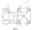
- FIG. 4shows the actuating arrangement 39 according to one embodiment.
- each of the piezoelectric disks 92is connected to a piezo driver 98 that communicates with a microprocessor 100 including a four-channel amplifier and analog-to-digital converter 102 that is connected to each of the force sensors 96 .
- the microprocessor 100is also in communication with the main processor 22 of the portable electronic device 20 .
- the microprocessor 100may provide signals to the main processor 22 and may receive signals form the main processor 22 .
- the piezo driver 98may be embodied in drive circuitry between the microprocessor 100 and the piezoelectric disks 92 .
- the mechanical work performed by the piezoelectric actuator 90may be controlled to provide generally consistent force and movement of the touch-sensitive input assembly 38 in response to detection of an applied force on the touch-sensitive input assembly 38 in the form of a touch, for example, and may provide movement of the touch-sensitive input assembly 38 to produce sound. Fluctuations in mechanical work performed as a result of, for example, temperature, may be reduced by modulating the current to control the charge.
- each piezoelectric disk 92has similar electrical properties to a capacitor.
- a coefficient, referred to as the D 31 coefficient of a piezoelectric material compositionprovides the relationship between voltage and force.
- the D 31 coefficient and the relative dielectric constant, (Er) of a given piezoelectric material compositionvary inversely with temperature, however. Therefore, if the charge of the piezoelectric disk 92 is controlled within a small range, the variance of the mechanical work of the piezoelectric actuator 90 may be small.
- Icurrent
- the microprocessor 100controls the PZT driver 98 for controlling the current to the piezoelectric disks 92 and thereby controlling the charge, increasing the charge to increase the force on the touch-sensitive input assembly 38 away from the base 82 and decreasing the charge to decrease the force on the touch-sensitive input assembly 38 , causing the touch-sensitive input assembly 38 to move toward the base 82 .
- each of the piezoelectric actuators 90are connected to the microprocessor 100 through the piezo driver 98 and are all controlled equally and concurrently.
- the portable electronic device 20is controlled generally by monitoring the orientation of the electronic device 20 based on signals from the accelerometer 41 and adjusting the driving signals to the piezoelectric disks 92 to control movement of the touch-sensitive input assembly 38 relative to the base 82 and thereby control sound generated from the movement.
- the portable electronic device 20may be designed such that when in an upright position, with the touch-sensitive input assembly 38 held vertically such that the touch-sensitive overlay 34 is generally parallel with a vertical plane, the touch-sensitive input assembly 38 moves relatively freely in equal distances both towards and away from base 82 . In this orientation, when an electrical signal in the form of a sine wave that is voltage symmetrical is applied to the actuating arrangement 39 , full physical motion of touch-sensitive input assembly 38 may be achieved. If the portable device is rotated into a horizontal position, in which the touch-sensitive overlay is held generally perpendicular to the vertical plane, the touch-sensitive input assembly 38 may be pushed down towards the base 82 as a result of gravity.
- the movement of the touch-sensitive input assembly 38may be limited by a mechanical stop that is formed by plunger 88 and support ring 91 .
- an offset voltageis applied to the electrical signal provided to the piezo actuators. This offset voltage counters the affect of gravity and re-positions the touch-sensitive input assembly 38 back to its natural rest position to facilitate full movement of the touch-sensitive input assembly 38 .
- a similar conditionis encountered when the portable device is an orientation in which the touch-sensitive input assembly 38 is facing down and the force of gravity is pushing touch-sensitive input assembly 38 away from base 82 . It will be appreciated that in this orientation, the compliant gasket 82 is compressed and reaches a position in which its spring constant is non-linear and may physically limit the movement of the touch-sensitive input assembly 38 in the direction away from the base. To compensate for the affect of gravity, an offset voltage is applied to the actuating arrangement 39 to re-position the touch-sensitive input assembly 38 back to its natural rest position to facilitate full movement of the touch-sensitive input assembly 38 . Orientation is determined using the information provided by accelerometer 41 .
- a portable handheld devicemay be subject to random movement when carried by a user, for example.
- the orientationis constantly monitored using information provided by accelerometer 41 .
- the electrical signal applied to the actuating arrangement 39may be modified accordingly to facilitate full movement of the touch-sensitive input assembly 38 .
- an extra margin for the electrical drive of the piezo actuators both in terms of the output transistors and in terms of the recommended operating voltage of the piezo actuatorsmay be employed.
- FIG. 5describes a method of controlling a portable electronic device in accordance with one embodiment. It will be appreciated that the steps of FIG. 5 may be carried out by routines or subroutines of software executed by, for example, the processor 22 . Coding of software for carrying out such steps is well within the scope of a person of ordinary skill in the art having regard to the present description.
- the methodstarts with the portable electronic device 20 entering a mode in which the touch-sensitive input arrangement 38 is used for audio output, for example, in a ringer mode upon receipt of an incoming call or a speakerphone mode during a telephone call (step 210 ).
- the audio signalis received at the portable electronic device 20 (step 220 ).
- the audio signalis a voice communication that is received at the portable electronic device 20 for output using the touch-sensitive input arrangement 38 .
- the audio signalis buffered, for example, in the RAM 28 , temporarily storing the signals prior to outputting to the piezoelectric actuators 90 (step 230 ).
- the orientation of the electronic deviceis determined based on signals from the accelerometer (step 240 ) and the adjustment for the audio signal is determined based on the orientation of the portable electronic device 20 (step 250 ).
- the adjustmentis dependent on the mass of the touch-sensitive input arrangement 38 , the orientation or angle that the portable electronic device 20 , and thus the position that the touch-sensitive input arrangement 38 , is held at during audio output.
- the adjustmentis based on the component of the force of gravity on the touch-sensitive input assembly 38 that acts to bend the piezoelectric actuators 90 between the base 82 and the touch-sensitive input arrangement 38 .
- the component of the force of gravityis 100% and the resulting adjustment is greater compared to the adjustment when the portable electronic device is held at some other angle to the ground.
- the audio signal adjustmentis therefore determined based on the determined orientation (step 250 ) and the buffered audio signals are adjusted accordingly to provide drive signals for the piezoelectric actuators 90 (step 260 ).
- the drive signalsare then sent to the piezoelectric actuators 90 for movement of the touch-sensitive input arrangement 38 to generate sound (step 270 ).
- the audio signalis a voice communication that is received at the portable electronic device 20 .
- the audio signalmay be memory for a ring or for vibratory notification.
- bufferingmay not occur as the audio is sampled out from the memory.
- the audio signalsare thereby adjusted based on the orientation of the portable electronic device 20 and based on the mass of the touch-sensitive input arrangement 38 to counter-act the effect of the component of gravity on the touch-sensitive input arrangement 38 that acts on the piezoelectric actuators 90 .
- the audio signalsare therefore pre-distorted to provide an audio output that is close to the desired output.
- FIG. 6is a flow chart illustrating a method of controlling the portable electronic device 20 to provide tactile feedback. It will be appreciated that the flow chart of FIG. 6 is simplified for the purpose of explanation. It will be appreciated that the steps of FIG. 6 may be carried out by routines or subroutines of software executed by, for example, the processor 22 or the microprocessor 100 . Coding of software for carrying out such steps is well within the scope of a person of ordinary skill in the art having regard to the present description.
- the touch-sensitive input assembly 38is monitored for a touch event and, in response to determination of a touch event (step 310 ), the charge at each of the piezoelectric disks 92 is modulated to modulate the force applied by the piezoelectric actuator 90 on the touch-sensitive input assembly 38 to cause movement of the touch-sensitive input assembly 38 for simulating the collapse of a dome-type switch (step 320 ).
- the charge at each of the piezoelectric disks 92is modulated to modulate the force applied by the piezoelectric actuators 90 to the touch-sensitive input assembly 38 to cause movement of the touch-sensitive input assembly 38 for simulating release of a dome-type switch (step 340 ).
- a further touch eventmay be detected again and the steps may be repeated, for example. Further, more than one touch event may occur such that a second touch event may be detected prior to the end of a first touch event.
- the charge at each of the piezoelectric disks 92may be modulated again to modulate the force applied by the piezoelectric actuators 90 to the touch-sensitive input assembly 38 to cause movement of the touch-sensitive input assembly 38 for simulating another collapse of a dome-type switch prior to the end of the first touch event being detected.
- a force on the touch-sensitive input assembly 38is detected through the force sensors 96 , as a result of a change in resistance at the force sensitive resistors.
- the forceis determined at the microprocessor 100 as a result of signals from the amplifier and four-channel analog to digital converter 102 connected to each of the force sensors 96 .
- the touch-sensitive input assembly 38is monitored for a touch event and a touch event on the touch-sensitive input assembly 38 may be detected.
- Such a touch eventmay be determined upon determination of an external applied force as a result of a user touch at the touch-sensitive input assembly 38 for selection of, for example, an Internet browser application, an email application, a calendar application, or any other suitable application, option, or other feature within an application (step 310 ).
- the touch eventis detected when the force measured at the force sensors 96 exceeds a minimum threshold force.
- the measured force at the force sensors 96is compared to a threshold force and a touch event is detected if the measured force is determined to exceed the threshold force.
- a touch eventis not detected as a result of a relatively light touch or brush on the touch-sensitive input assembly 38 with a measured force that is lower than the threshold force. It will be appreciated that the touch-sensitive input surface 34 is thereby monitored for a touch event.
- a suitable currentis applied to the piezoelectric actuator 90 , ramping up the charge over a period of time causing flexing of the piezoelectric actuator 90 and a resulting force applied to the touch-sensitive input assembly 38 through the support tray 84 .
- the chargeis ramped up over a period of time so that the user does not detect the force applied by the piezoelectric actuators 90 on the touch-sensitive input assembly 38 .
- the electrical chargeis reduced by a suitable controlled discharge current and the resulting force applied by the piezoelectric actuator 90 on the touch-sensitive input assembly 38 is reduced over a very short period of time relative to the period of time for ramping up the charge, for simulating collapse of a dome-type switch (step 320 ).
- the end of the touch eventis detected (step 330 ).
- the end of the touch eventis detected.
- the predetermined forcemay be lower than the threshold force described above for reducing the chance of false detection of an end of a touch event and successive start of another touch event if the external applied force hovers such that the measured force hovers at about the threshold applied force.
- a suitable currentis applied to the piezoelectric actuator 90 , causing an increase in charge, flexing of the piezoelectric actuator 90 and a resulting force to be applied to the touch-sensitive input assembly 38 through the support tray 84 over a relatively short period of time compared to the period of time for ramping up the charge, for simulating release of a dome-type switch (step 340 ).
- the electrical chargeis reduced and the resulting force applied by the piezoelectric actuator 90 on the touch-sensitive input assembly 38 is reduced by ramping down over a long period of time compared to the period of time for increasing charge to simulate release.
- the charge and/or discharge current applied to the piezoelectric disk 92is therefore modulated to modulate the force from the piezoelectric actuators 90 on the touch-sensitive input assembly 38 for providing a desirable tactile feedback by simulating collapse of a dome-type switch in response to detection of the touch event and by simulating release of a dome-type switch upon detection of an end of the touch event.
- a piezoelectric patch transducer or multiple piezoelectric patch transducersmay be used.
- an electrostrictive materialmay be used rather than a piezoelectric material.
- a magnetostrictive materialmay also be employed.
- an electroactive polymermay be used rather than a piezo actuator.
- the actuating arrangementprovides a relatively thin device for providing audio output as well as tactile feedback to the user without adding significantly to the thickness of the device.
- the piezoelectric actuatorsare driven to cause movement of the touch-sensitive input arrangement and thereby produce sound rather than using an additional speaker. Audio signals are adjusted to compensate for the effects of gravity on the touch-sensitive input arrangement.
- a touch-sensitive display devicefor example, may be used as an audio transducer in a speakerphone or ringer, thereby saving the cost of the speaker used for such functions and the volume of space of such a speaker and air cavity within the electronic device.
- An electronic deviceincludes a housing including a base, a touch-sensitive input assembly coupled to the housing and spaced from and moveable relative to the base to generate sound, an accelerometer housed within the housing, an actuating arrangement comprising a piezoelectric actuator between the base and the touch-sensitive input surface and arranged to receive a driving signal and move the touch-sensitive input surface relative to the base, and functional components in the housing comprising a memory and a processor operably coupled to the memory, the touch-sensitive input assembly, the actuating arrangement, and the accelerometer to execute a program stored in the memory to determine an orientation of the electronic device and adjust the driving signal to the actuating arrangement based on the orientation of the electronic device.
- a method of controlling the electronic deviceincludes determining an orientation of the electronic device and adjusting the driving signal to the actuating arrangement based on the orientation of the electronic device.
- a computer-readable mediumhas computer-readable code embodied therein for execution by a processor in the electronic device to cause the electronic device to determine an orientation of the electronic device, and adjust the driving signal to the actuating arrangement based on the orientation of the electronic device.
- the piezoelectric actuatorsare driven to cause movement of the touch-sensitive input arrangement and thereby produce sound rather than, or in addition to, using an additional speaker.
- Audio signalsare adjusted to compensate for the effects of gravity on the touch-sensitive input arrangement, that may distort or alter the sound depending on the orientation of the electronic device.
- a touch-sensitive displayfor example, may be used as an audio transducer in a speakerphone or ringer, thereby saving the cost of the speaker used for such functions and the volume of space of such a speaker and air cavity within the electronic device.
- the touch-sensitive displaymay provide more sound pressure level, extended frequency response and/or enhanced special effects when used with a speaker.
- the actuating arrangementalso provides desirable tactile feedback in response to a touch event on the touch-sensitive display.
- Controlling the piezoelectric actuator or actuators to simulate actuation of a dome-type switch upon touching the touch-sensitive input surfaceprovides a desirable tactile feedback for confirming receipt of input to the user, thereby providing a positive response and reducing the chance of input errors such as double entry, decreasing use time and increasing user-satisfaction. Additionally, the actuating arrangement acting on the touch-sensitive input arrangement may provide vibratory response or notification.
Landscapes
- Engineering & Computer Science (AREA)
- General Engineering & Computer Science (AREA)
- Theoretical Computer Science (AREA)
- Human Computer Interaction (AREA)
- Physics & Mathematics (AREA)
- General Physics & Mathematics (AREA)
- Telephone Function (AREA)
- User Interface Of Digital Computer (AREA)
Abstract
Description
Qpiezo=Cpiezo*Vpiezo
- C is capacitance; and
- V is voltage.
I=C*dV/dT
- C is capacitance; and
- dV/dT is differential voltage or instantaneous rate of voltage change.
With I and dT held constant, then as C decreases, dV increases. Thus the charge is controlled since Qpiezo=Cpiezo*Vpiezo.
Claims (15)
Priority Applications (1)
| Application Number | Priority Date | Filing Date | Title |
|---|---|---|---|
| US12/497,724US8310458B2 (en) | 2009-07-06 | 2009-07-06 | Electronic device including a moveable touch-sensitive input and method of controlling same |
Applications Claiming Priority (1)
| Application Number | Priority Date | Filing Date | Title |
|---|---|---|---|
| US12/497,724US8310458B2 (en) | 2009-07-06 | 2009-07-06 | Electronic device including a moveable touch-sensitive input and method of controlling same |
Publications (2)
| Publication Number | Publication Date |
|---|---|
| US20110001707A1 US20110001707A1 (en) | 2011-01-06 |
| US8310458B2true US8310458B2 (en) | 2012-11-13 |
Family
ID=43412374
Family Applications (1)
| Application Number | Title | Priority Date | Filing Date |
|---|---|---|---|
| US12/497,724Active2031-05-15US8310458B2 (en) | 2009-07-06 | 2009-07-06 | Electronic device including a moveable touch-sensitive input and method of controlling same |
Country Status (1)
| Country | Link |
|---|---|
| US (1) | US8310458B2 (en) |
Cited By (49)
| Publication number | Priority date | Publication date | Assignee | Title |
|---|---|---|---|---|
| US20110187674A1 (en)* | 2010-02-03 | 2011-08-04 | Interlink Electronics, Inc. | Sensor system |
| US20120062491A1 (en)* | 2010-09-14 | 2012-03-15 | Thales | Haptic interaction device and method for generating haptic and sound effects |
| US20120263325A1 (en)* | 2011-04-14 | 2012-10-18 | Bose Corporation | Orientation-Responsive Acoustic Array Control |
| US20120263335A1 (en)* | 2011-04-14 | 2012-10-18 | Breen John J | Orientation-Responsive Use of Acoustic Reflection |
| US20120263324A1 (en)* | 2011-04-14 | 2012-10-18 | John Joyce | Orientation-Responsive Acoustic Driver Selection |
| US20130250502A1 (en)* | 2010-10-19 | 2013-09-26 | Nokia Corporation | Display apparatus |
| US8547339B2 (en) | 2008-01-04 | 2013-10-01 | Tactus Technology, Inc. | System and methods for raised touch screens |
| US8553005B2 (en) | 2008-01-04 | 2013-10-08 | Tactus Technology, Inc. | User interface system |
| US8570295B2 (en) | 2008-01-04 | 2013-10-29 | Tactus Technology, Inc. | User interface system |
| US8587548B2 (en) | 2009-07-03 | 2013-11-19 | Tactus Technology, Inc. | Method for adjusting the user interface of a device |
| US8619035B2 (en) | 2010-02-10 | 2013-12-31 | Tactus Technology, Inc. | Method for assisting user input to a device |
| US20140306914A1 (en)* | 2011-12-27 | 2014-10-16 | Murata Manufacturing Co., Ltd. | Tactile presentation device |
| US8922503B2 (en) | 2008-01-04 | 2014-12-30 | Tactus Technology, Inc. | User interface system |
| US8922502B2 (en) | 2008-01-04 | 2014-12-30 | Tactus Technology, Inc. | User interface system |
| US8922510B2 (en) | 2008-01-04 | 2014-12-30 | Tactus Technology, Inc. | User interface system |
| US8928621B2 (en) | 2008-01-04 | 2015-01-06 | Tactus Technology, Inc. | User interface system and method |
| US8947383B2 (en) | 2008-01-04 | 2015-02-03 | Tactus Technology, Inc. | User interface system and method |
| US8970403B2 (en) | 2008-01-04 | 2015-03-03 | Tactus Technology, Inc. | Method for actuating a tactile interface layer |
| US9019228B2 (en) | 2008-01-04 | 2015-04-28 | Tactus Technology, Inc. | User interface system |
| US9052790B2 (en) | 2008-01-04 | 2015-06-09 | Tactus Technology, Inc. | User interface and methods |
| US9063627B2 (en) | 2008-01-04 | 2015-06-23 | Tactus Technology, Inc. | User interface and methods |
| US9075525B2 (en) | 2008-01-04 | 2015-07-07 | Tactus Technology, Inc. | User interface system |
| US9098141B2 (en) | 2008-01-04 | 2015-08-04 | Tactus Technology, Inc. | User interface system |
| US9116617B2 (en) | 2009-07-03 | 2015-08-25 | Tactus Technology, Inc. | User interface enhancement system |
| US9239623B2 (en) | 2010-01-05 | 2016-01-19 | Tactus Technology, Inc. | Dynamic tactile interface |
| US9274612B2 (en) | 2008-01-04 | 2016-03-01 | Tactus Technology, Inc. | User interface system |
| US9280224B2 (en) | 2012-09-24 | 2016-03-08 | Tactus Technology, Inc. | Dynamic tactile interface and methods |
| US9298261B2 (en) | 2008-01-04 | 2016-03-29 | Tactus Technology, Inc. | Method for actuating a tactile interface layer |
| US9372565B2 (en) | 2008-01-04 | 2016-06-21 | Tactus Technology, Inc. | Dynamic tactile interface |
| US9405417B2 (en) | 2012-09-24 | 2016-08-02 | Tactus Technology, Inc. | Dynamic tactile interface and methods |
| US9423875B2 (en) | 2008-01-04 | 2016-08-23 | Tactus Technology, Inc. | Dynamic tactile interface with exhibiting optical dispersion characteristics |
| US9477308B2 (en) | 2008-01-04 | 2016-10-25 | Tactus Technology, Inc. | User interface system |
| US9510068B2 (en) | 2014-04-07 | 2016-11-29 | Bose Corporation | Automatic equalization of loudspeaker array |
| US9552065B2 (en) | 2008-01-04 | 2017-01-24 | Tactus Technology, Inc. | Dynamic tactile interface |
| US9557813B2 (en) | 2013-06-28 | 2017-01-31 | Tactus Technology, Inc. | Method for reducing perceived optical distortion |
| US9557915B2 (en) | 2008-01-04 | 2017-01-31 | Tactus Technology, Inc. | Dynamic tactile interface |
| US9588684B2 (en) | 2009-01-05 | 2017-03-07 | Tactus Technology, Inc. | Tactile interface for a computing device |
| US9588683B2 (en) | 2008-01-04 | 2017-03-07 | Tactus Technology, Inc. | Dynamic tactile interface |
| US9612659B2 (en) | 2008-01-04 | 2017-04-04 | Tactus Technology, Inc. | User interface system |
| US9720501B2 (en) | 2008-01-04 | 2017-08-01 | Tactus Technology, Inc. | Dynamic tactile interface |
| US9760172B2 (en) | 2008-01-04 | 2017-09-12 | Tactus Technology, Inc. | Dynamic tactile interface |
| US10019063B2 (en)* | 2013-05-24 | 2018-07-10 | New York University | Haptic force-feedback for computing interfaces |
| US10506087B2 (en) | 2018-02-01 | 2019-12-10 | Microsoft Technology Licensing, Llc | Electroactive perimeter stiffener |
| US10659886B2 (en)* | 2016-03-25 | 2020-05-19 | Samsung Electronics Co., Ltd. | Electronic device and sound output method thereof |
| US10706252B2 (en) | 2013-07-25 | 2020-07-07 | Apple Inc. | Electronic device with strain-based force sensor |
| US10739855B2 (en) | 2016-03-31 | 2020-08-11 | Apple Inc. | Electronic device configured to collect biometric and amount of force data when a user touches a displayed image |
| US10739899B2 (en) | 2014-02-12 | 2020-08-11 | Apple Inc. | Force determination employing sheet sensor |
| US10817096B2 (en) | 2014-02-06 | 2020-10-27 | Apple Inc. | Force sensor incorporated into display |
| US11380334B1 (en) | 2011-03-01 | 2022-07-05 | Intelligible English LLC | Methods and systems for interactive online language learning in a pandemic-aware world |
Families Citing this family (68)
| Publication number | Priority date | Publication date | Assignee | Title |
|---|---|---|---|---|
| US20100328229A1 (en)* | 2009-06-30 | 2010-12-30 | Research In Motion Limited | Method and apparatus for providing tactile feedback |
| US8854314B2 (en)* | 2009-09-29 | 2014-10-07 | Alcatel Lucent | Universal interface device with housing sensor array adapted for detection of distributed touch input |
| KR101915158B1 (en)* | 2011-04-14 | 2018-11-06 | 보세 코포레이션 | Orientation-responsive acoustic driver operation |
| US9639213B2 (en) | 2011-04-26 | 2017-05-02 | Sentons Inc. | Using multiple signals to detect touch input |
| US9477350B2 (en) | 2011-04-26 | 2016-10-25 | Sentons Inc. | Method and apparatus for active ultrasonic touch devices |
| US9189109B2 (en) | 2012-07-18 | 2015-11-17 | Sentons Inc. | Detection of type of object used to provide a touch contact input |
| US11327599B2 (en) | 2011-04-26 | 2022-05-10 | Sentons Inc. | Identifying a contact type |
| US10198097B2 (en) | 2011-04-26 | 2019-02-05 | Sentons Inc. | Detecting touch input force |
| US8975903B2 (en) | 2011-06-09 | 2015-03-10 | Ford Global Technologies, Llc | Proximity switch having learned sensitivity and method therefor |
| US8928336B2 (en) | 2011-06-09 | 2015-01-06 | Ford Global Technologies, Llc | Proximity switch having sensitivity control and method therefor |
| US10004286B2 (en) | 2011-08-08 | 2018-06-26 | Ford Global Technologies, Llc | Glove having conductive ink and method of interacting with proximity sensor |
| US9143126B2 (en) | 2011-09-22 | 2015-09-22 | Ford Global Technologies, Llc | Proximity switch having lockout control for controlling movable panel |
| US8994228B2 (en) | 2011-11-03 | 2015-03-31 | Ford Global Technologies, Llc | Proximity switch having wrong touch feedback |
| US10112556B2 (en) | 2011-11-03 | 2018-10-30 | Ford Global Technologies, Llc | Proximity switch having wrong touch adaptive learning and method |
| US8878438B2 (en) | 2011-11-04 | 2014-11-04 | Ford Global Technologies, Llc | Lamp and proximity switch assembly and method |
| US10248262B2 (en) | 2011-11-18 | 2019-04-02 | Sentons Inc. | User interface interaction using touch input force |
| EP3627296B1 (en) | 2011-11-18 | 2021-06-23 | Sentons Inc. | Localized haptic feedback |
| US10235004B1 (en) | 2011-11-18 | 2019-03-19 | Sentons Inc. | Touch input detector with an integrated antenna |
| US9886091B2 (en) | 2012-03-15 | 2018-02-06 | Nokia Technologies Oy | Tactile apparatus link |
| US9660644B2 (en) | 2012-04-11 | 2017-05-23 | Ford Global Technologies, Llc | Proximity switch assembly and activation method |
| US9065447B2 (en) | 2012-04-11 | 2015-06-23 | Ford Global Technologies, Llc | Proximity switch assembly and method having adaptive time delay |
| US9559688B2 (en) | 2012-04-11 | 2017-01-31 | Ford Global Technologies, Llc | Proximity switch assembly having pliable surface and depression |
| US9831870B2 (en) | 2012-04-11 | 2017-11-28 | Ford Global Technologies, Llc | Proximity switch assembly and method of tuning same |
| US8933708B2 (en) | 2012-04-11 | 2015-01-13 | Ford Global Technologies, Llc | Proximity switch assembly and activation method with exploration mode |
| US9219472B2 (en) | 2012-04-11 | 2015-12-22 | Ford Global Technologies, Llc | Proximity switch assembly and activation method using rate monitoring |
| US9944237B2 (en) | 2012-04-11 | 2018-04-17 | Ford Global Technologies, Llc | Proximity switch assembly with signal drift rejection and method |
| US9197206B2 (en) | 2012-04-11 | 2015-11-24 | Ford Global Technologies, Llc | Proximity switch having differential contact surface |
| US9184745B2 (en) | 2012-04-11 | 2015-11-10 | Ford Global Technologies, Llc | Proximity switch assembly and method of sensing user input based on signal rate of change |
| US9520875B2 (en) | 2012-04-11 | 2016-12-13 | Ford Global Technologies, Llc | Pliable proximity switch assembly and activation method |
| US9531379B2 (en) | 2012-04-11 | 2016-12-27 | Ford Global Technologies, Llc | Proximity switch assembly having groove between adjacent proximity sensors |
| US9568527B2 (en) | 2012-04-11 | 2017-02-14 | Ford Global Technologies, Llc | Proximity switch assembly and activation method having virtual button mode |
| US9287864B2 (en) | 2012-04-11 | 2016-03-15 | Ford Global Technologies, Llc | Proximity switch assembly and calibration method therefor |
| WO2013160560A1 (en)* | 2012-04-26 | 2013-10-31 | Screentec Oy | Touch display and method for manufacturing touch display |
| US9136840B2 (en) | 2012-05-17 | 2015-09-15 | Ford Global Technologies, Llc | Proximity switch assembly having dynamic tuned threshold |
| US8981602B2 (en) | 2012-05-29 | 2015-03-17 | Ford Global Technologies, Llc | Proximity switch assembly having non-switch contact and method |
| US9337832B2 (en) | 2012-06-06 | 2016-05-10 | Ford Global Technologies, Llc | Proximity switch and method of adjusting sensitivity therefor |
| US9641172B2 (en) | 2012-06-27 | 2017-05-02 | Ford Global Technologies, Llc | Proximity switch assembly having varying size electrode fingers |
| US9513727B2 (en)* | 2012-07-18 | 2016-12-06 | Sentons Inc. | Touch input surface microphone |
| US9348468B2 (en) | 2013-06-07 | 2016-05-24 | Sentons Inc. | Detecting multi-touch inputs |
| US8922340B2 (en) | 2012-09-11 | 2014-12-30 | Ford Global Technologies, Llc | Proximity switch based door latch release |
| US8796575B2 (en) | 2012-10-31 | 2014-08-05 | Ford Global Technologies, Llc | Proximity switch assembly having ground layer |
| US10386970B2 (en)* | 2013-02-08 | 2019-08-20 | Apple Inc. | Force determination based on capacitive sensing |
| US9311204B2 (en) | 2013-03-13 | 2016-04-12 | Ford Global Technologies, Llc | Proximity interface development system having replicator and method |
| US9280259B2 (en) | 2013-07-26 | 2016-03-08 | Blackberry Limited | System and method for manipulating an object in a three-dimensional desktop environment |
| US9390598B2 (en) | 2013-09-11 | 2016-07-12 | Blackberry Limited | Three dimensional haptics hybrid modeling |
| US9459715B1 (en) | 2013-09-20 | 2016-10-04 | Sentons Inc. | Using spectral control in detecting touch input |
| EP3964931B1 (en) | 2014-09-02 | 2025-05-07 | Apple Inc. | Semantic framework for variable haptic output |
| US10038443B2 (en) | 2014-10-20 | 2018-07-31 | Ford Global Technologies, Llc | Directional proximity switch assembly |
| US9654103B2 (en) | 2015-03-18 | 2017-05-16 | Ford Global Technologies, Llc | Proximity switch assembly having haptic feedback and method |
| US9548733B2 (en) | 2015-05-20 | 2017-01-17 | Ford Global Technologies, Llc | Proximity sensor assembly having interleaved electrode configuration |
| US10372212B2 (en)* | 2015-05-29 | 2019-08-06 | Google Llc | Techniques for simulated physical interaction between users via their mobile computing devices |
| US10048811B2 (en) | 2015-09-18 | 2018-08-14 | Sentons Inc. | Detecting touch input provided by signal transmitting stylus |
| DK180122B1 (en) | 2016-06-12 | 2020-05-19 | Apple Inc. | Devices, methods and graphical user interfaces for providing haptic feedback |
| DK179823B1 (en) | 2016-06-12 | 2019-07-12 | Apple Inc. | Devices, methods, and graphical user interfaces for providing haptic feedback |
| DK201670720A1 (en) | 2016-09-06 | 2018-03-26 | Apple Inc | Devices, Methods, and Graphical User Interfaces for Generating Tactile Outputs |
| DK179278B1 (en) | 2016-09-06 | 2018-03-26 | Apple Inc | Devices, methods and graphical user interfaces for haptic mixing |
| US10908741B2 (en) | 2016-11-10 | 2021-02-02 | Sentons Inc. | Touch input detection along device sidewall |
| US10296144B2 (en) | 2016-12-12 | 2019-05-21 | Sentons Inc. | Touch input detection with shared receivers |
| US10126877B1 (en) | 2017-02-01 | 2018-11-13 | Sentons Inc. | Update of reference data for touch input detection |
| US10585522B2 (en) | 2017-02-27 | 2020-03-10 | Sentons Inc. | Detection of non-touch inputs using a signature |
| DK201770372A1 (en) | 2017-05-16 | 2019-01-08 | Apple Inc. | Tactile feedback for locked device user interfaces |
| US11009411B2 (en) | 2017-08-14 | 2021-05-18 | Sentons Inc. | Increasing sensitivity of a sensor using an encoded signal |
| US11580829B2 (en) | 2017-08-14 | 2023-02-14 | Sentons Inc. | Dynamic feedback for haptics |
| CN107908317B (en)* | 2017-10-27 | 2020-10-09 | 上海飞智电子科技有限公司 | Touch device and touch method applied to capacitive touch screen |
| KR101899538B1 (en)* | 2017-11-13 | 2018-09-19 | 주식회사 씨케이머티리얼즈랩 | Apparatus and method for providing haptic control signal |
| CN108572694A (en)* | 2018-02-28 | 2018-09-25 | 太仓鸿恩电子科技有限公司 | The notebook computer casing and its process of surface treatment of ultra-thin impact resistance |
| US20200379599A1 (en)* | 2018-07-25 | 2020-12-03 | Shanghai Flydigi Electronics Technology Co., Ltd. | Touch control device applied to capacitive touch screen, processing device, and touch control system |
| CN112491323B (en)* | 2020-11-27 | 2022-04-26 | 瑞声新能源发展(常州)有限公司科教城分公司 | Linear motor over-stroke control method and device, computer equipment and storage medium |
Citations (11)
| Publication number | Priority date | Publication date | Assignee | Title |
|---|---|---|---|---|
| US20040156168A1 (en)* | 2003-02-12 | 2004-08-12 | Levasseur Lewis H. | Sealed force-based touch sensor |
| WO2004107808A2 (en) | 2003-05-28 | 2004-12-09 | Koninklijke Philips Electronics N.V. | Display screen loudspeaker |
| EP1542064A1 (en) | 2002-09-03 | 2005-06-15 | Sharp Kabushiki Kaisha | Liquid crystal display device having sound output function and the like and electronic device using the same |
| US20050280746A1 (en)* | 2004-06-16 | 2005-12-22 | Kenneth North | Stress seal for touchscreen systems |
| US20060017692A1 (en)* | 2000-10-02 | 2006-01-26 | Wehrenberg Paul J | Methods and apparatuses for operating a portable device based on an accelerometer |
| US20060022952A1 (en)* | 2004-07-07 | 2006-02-02 | Matti Ryynanen | Electrostrictive polymer as a combined haptic-seal actuator |
| US20060119586A1 (en) | 2004-10-08 | 2006-06-08 | Immersion Corporation, A Delaware Corporation | Haptic feedback for button and scrolling action simulation in touch input devices |
| US20060181517A1 (en)* | 2005-02-11 | 2006-08-17 | Apple Computer, Inc. | Display actuator |
| US20070013677A1 (en)* | 1998-06-23 | 2007-01-18 | Immersion Corporation | Haptic feedback for touchpads and other touch controls |
| US20080122315A1 (en)* | 2006-11-15 | 2008-05-29 | Sony Corporation | Substrate supporting vibration structure, input device having haptic function, and electronic device |
| US20080214160A1 (en)* | 2007-03-01 | 2008-09-04 | Sony Ericsson Mobile Communications Ab | Motion-controlled audio output |
- 2009
- 2009-07-06USUS12/497,724patent/US8310458B2/enactiveActive
Patent Citations (11)
| Publication number | Priority date | Publication date | Assignee | Title |
|---|---|---|---|---|
| US20070013677A1 (en)* | 1998-06-23 | 2007-01-18 | Immersion Corporation | Haptic feedback for touchpads and other touch controls |
| US20060017692A1 (en)* | 2000-10-02 | 2006-01-26 | Wehrenberg Paul J | Methods and apparatuses for operating a portable device based on an accelerometer |
| EP1542064A1 (en) | 2002-09-03 | 2005-06-15 | Sharp Kabushiki Kaisha | Liquid crystal display device having sound output function and the like and electronic device using the same |
| US20040156168A1 (en)* | 2003-02-12 | 2004-08-12 | Levasseur Lewis H. | Sealed force-based touch sensor |
| WO2004107808A2 (en) | 2003-05-28 | 2004-12-09 | Koninklijke Philips Electronics N.V. | Display screen loudspeaker |
| US20050280746A1 (en)* | 2004-06-16 | 2005-12-22 | Kenneth North | Stress seal for touchscreen systems |
| US20060022952A1 (en)* | 2004-07-07 | 2006-02-02 | Matti Ryynanen | Electrostrictive polymer as a combined haptic-seal actuator |
| US20060119586A1 (en) | 2004-10-08 | 2006-06-08 | Immersion Corporation, A Delaware Corporation | Haptic feedback for button and scrolling action simulation in touch input devices |
| US20060181517A1 (en)* | 2005-02-11 | 2006-08-17 | Apple Computer, Inc. | Display actuator |
| US20080122315A1 (en)* | 2006-11-15 | 2008-05-29 | Sony Corporation | Substrate supporting vibration structure, input device having haptic function, and electronic device |
| US20080214160A1 (en)* | 2007-03-01 | 2008-09-04 | Sony Ericsson Mobile Communications Ab | Motion-controlled audio output |
Non-Patent Citations (4)
| Title |
|---|
| EESR issued in corresponding European Patent Application EP 09164676 dated Nov. 24, 2009. |
| Lashkari et al., Loudspeaker Linearization Using Perceptual Distortion Measures, Signals, Systems and Computers, 2003, pp. 745-749, vol. 1, IEEE, San Jose, USA. |
| Poupyrev I et al, "Tactile Interfaces for Small Touch Screens" Jan. 1, 2003. |
| Raising the Standards for Mobile Phone Audio, Jul. 6, 2009, www.nxtsound.com/index?id=406. |
Cited By (75)
| Publication number | Priority date | Publication date | Assignee | Title |
|---|---|---|---|---|
| US9274612B2 (en) | 2008-01-04 | 2016-03-01 | Tactus Technology, Inc. | User interface system |
| US9760172B2 (en) | 2008-01-04 | 2017-09-12 | Tactus Technology, Inc. | Dynamic tactile interface |
| US9720501B2 (en) | 2008-01-04 | 2017-08-01 | Tactus Technology, Inc. | Dynamic tactile interface |
| US9626059B2 (en) | 2008-01-04 | 2017-04-18 | Tactus Technology, Inc. | User interface system |
| US9619030B2 (en) | 2008-01-04 | 2017-04-11 | Tactus Technology, Inc. | User interface system and method |
| US9612659B2 (en) | 2008-01-04 | 2017-04-04 | Tactus Technology, Inc. | User interface system |
| US8547339B2 (en) | 2008-01-04 | 2013-10-01 | Tactus Technology, Inc. | System and methods for raised touch screens |
| US8553005B2 (en) | 2008-01-04 | 2013-10-08 | Tactus Technology, Inc. | User interface system |
| US8570295B2 (en) | 2008-01-04 | 2013-10-29 | Tactus Technology, Inc. | User interface system |
| US9588683B2 (en) | 2008-01-04 | 2017-03-07 | Tactus Technology, Inc. | Dynamic tactile interface |
| US9557915B2 (en) | 2008-01-04 | 2017-01-31 | Tactus Technology, Inc. | Dynamic tactile interface |
| US9552065B2 (en) | 2008-01-04 | 2017-01-24 | Tactus Technology, Inc. | Dynamic tactile interface |
| US8717326B2 (en) | 2008-01-04 | 2014-05-06 | Tactus Technology, Inc. | System and methods for raised touch screens |
| US9524025B2 (en) | 2008-01-04 | 2016-12-20 | Tactus Technology, Inc. | User interface system and method |
| US9495055B2 (en) | 2008-01-04 | 2016-11-15 | Tactus Technology, Inc. | User interface and methods |
| US8922503B2 (en) | 2008-01-04 | 2014-12-30 | Tactus Technology, Inc. | User interface system |
| US8922502B2 (en) | 2008-01-04 | 2014-12-30 | Tactus Technology, Inc. | User interface system |
| US8922510B2 (en) | 2008-01-04 | 2014-12-30 | Tactus Technology, Inc. | User interface system |
| US8928621B2 (en) | 2008-01-04 | 2015-01-06 | Tactus Technology, Inc. | User interface system and method |
| US9477308B2 (en) | 2008-01-04 | 2016-10-25 | Tactus Technology, Inc. | User interface system |
| US9448630B2 (en) | 2008-01-04 | 2016-09-20 | Tactus Technology, Inc. | Method for actuating a tactile interface layer |
| US8947383B2 (en) | 2008-01-04 | 2015-02-03 | Tactus Technology, Inc. | User interface system and method |
| US8970403B2 (en) | 2008-01-04 | 2015-03-03 | Tactus Technology, Inc. | Method for actuating a tactile interface layer |
| US9019228B2 (en) | 2008-01-04 | 2015-04-28 | Tactus Technology, Inc. | User interface system |
| US9035898B2 (en) | 2008-01-04 | 2015-05-19 | Tactus Technology, Inc. | System and methods for raised touch screens |
| US9430074B2 (en) | 2008-01-04 | 2016-08-30 | Tactus Technology, Inc. | Dynamic tactile interface |
| US9052790B2 (en) | 2008-01-04 | 2015-06-09 | Tactus Technology, Inc. | User interface and methods |
| US9063627B2 (en) | 2008-01-04 | 2015-06-23 | Tactus Technology, Inc. | User interface and methods |
| US9075525B2 (en) | 2008-01-04 | 2015-07-07 | Tactus Technology, Inc. | User interface system |
| US9098141B2 (en) | 2008-01-04 | 2015-08-04 | Tactus Technology, Inc. | User interface system |
| US9423875B2 (en) | 2008-01-04 | 2016-08-23 | Tactus Technology, Inc. | Dynamic tactile interface with exhibiting optical dispersion characteristics |
| US9207795B2 (en) | 2008-01-04 | 2015-12-08 | Tactus Technology, Inc. | User interface system |
| US9229571B2 (en) | 2008-01-04 | 2016-01-05 | Tactus Technology, Inc. | Method for adjusting the user interface of a device |
| US9372565B2 (en) | 2008-01-04 | 2016-06-21 | Tactus Technology, Inc. | Dynamic tactile interface |
| US9372539B2 (en) | 2008-01-04 | 2016-06-21 | Tactus Technology, Inc. | Method for actuating a tactile interface layer |
| US9298261B2 (en) | 2008-01-04 | 2016-03-29 | Tactus Technology, Inc. | Method for actuating a tactile interface layer |
| US9588684B2 (en) | 2009-01-05 | 2017-03-07 | Tactus Technology, Inc. | Tactile interface for a computing device |
| US8587548B2 (en) | 2009-07-03 | 2013-11-19 | Tactus Technology, Inc. | Method for adjusting the user interface of a device |
| US9116617B2 (en) | 2009-07-03 | 2015-08-25 | Tactus Technology, Inc. | User interface enhancement system |
| US9298262B2 (en) | 2010-01-05 | 2016-03-29 | Tactus Technology, Inc. | Dynamic tactile interface |
| US9239623B2 (en) | 2010-01-05 | 2016-01-19 | Tactus Technology, Inc. | Dynamic tactile interface |
| US8669963B2 (en)* | 2010-02-03 | 2014-03-11 | Interlink Electronics, Inc. | Sensor system |
| US20110187674A1 (en)* | 2010-02-03 | 2011-08-04 | Interlink Electronics, Inc. | Sensor system |
| US8619035B2 (en) | 2010-02-10 | 2013-12-31 | Tactus Technology, Inc. | Method for assisting user input to a device |
| US20120062491A1 (en)* | 2010-09-14 | 2012-03-15 | Thales | Haptic interaction device and method for generating haptic and sound effects |
| US10638617B2 (en)* | 2010-10-19 | 2020-04-28 | Nokia Technologies Oy | Display apparatus |
| US20130250502A1 (en)* | 2010-10-19 | 2013-09-26 | Nokia Corporation | Display apparatus |
| US11380334B1 (en) | 2011-03-01 | 2022-07-05 | Intelligible English LLC | Methods and systems for interactive online language learning in a pandemic-aware world |
| US9049518B2 (en)* | 2011-04-14 | 2015-06-02 | Bose Corporation | Orientation-responsive acoustic array control |
| US20160119735A1 (en)* | 2011-04-14 | 2016-04-28 | Bose Corporation | Orientation-Responsive Acoustic Array Control |
| US11388536B2 (en)* | 2011-04-14 | 2022-07-12 | Bose Corporation | Orientation-responsive acoustic array control |
| US20140205133A1 (en)* | 2011-04-14 | 2014-07-24 | Bose Corporation | Orientation-Responsive Acoustic Array Control |
| US8934655B2 (en)* | 2011-04-14 | 2015-01-13 | Bose Corporation | Orientation-responsive use of acoustic reflection |
| US9264794B2 (en)* | 2011-04-14 | 2016-02-16 | Bose Corporation | Orientation-responsive acoustic array control |
| US8934647B2 (en)* | 2011-04-14 | 2015-01-13 | Bose Corporation | Orientation-responsive acoustic driver selection |
| US10264384B2 (en)* | 2011-04-14 | 2019-04-16 | Bose Corporation | Orientation-responsive acoustic array control |
| US9736612B2 (en)* | 2011-04-14 | 2017-08-15 | Bose Corporation | Orientation-responsive acoustic array control |
| US9253561B2 (en)* | 2011-04-14 | 2016-02-02 | Bose Corporation | Orientation-responsive acoustic array control |
| US20120263324A1 (en)* | 2011-04-14 | 2012-10-18 | John Joyce | Orientation-Responsive Acoustic Driver Selection |
| US20120263335A1 (en)* | 2011-04-14 | 2012-10-18 | Breen John J | Orientation-Responsive Use of Acoustic Reflection |
| US20170180852A1 (en)* | 2011-04-14 | 2017-06-22 | Bose Corporation | Orientation-Responsive Acoustic Array Control |
| US20120263325A1 (en)* | 2011-04-14 | 2012-10-18 | Bose Corporation | Orientation-Responsive Acoustic Array Control |
| US9348414B2 (en)* | 2011-12-27 | 2016-05-24 | Murata Manufacturing Co., Ltd. | Tactile presentation device |
| US20140306914A1 (en)* | 2011-12-27 | 2014-10-16 | Murata Manufacturing Co., Ltd. | Tactile presentation device |
| US9405417B2 (en) | 2012-09-24 | 2016-08-02 | Tactus Technology, Inc. | Dynamic tactile interface and methods |
| US9280224B2 (en) | 2012-09-24 | 2016-03-08 | Tactus Technology, Inc. | Dynamic tactile interface and methods |
| US10019063B2 (en)* | 2013-05-24 | 2018-07-10 | New York University | Haptic force-feedback for computing interfaces |
| US9557813B2 (en) | 2013-06-28 | 2017-01-31 | Tactus Technology, Inc. | Method for reducing perceived optical distortion |
| US10706252B2 (en) | 2013-07-25 | 2020-07-07 | Apple Inc. | Electronic device with strain-based force sensor |
| US10817096B2 (en) | 2014-02-06 | 2020-10-27 | Apple Inc. | Force sensor incorporated into display |
| US10739899B2 (en) | 2014-02-12 | 2020-08-11 | Apple Inc. | Force determination employing sheet sensor |
| US9510068B2 (en) | 2014-04-07 | 2016-11-29 | Bose Corporation | Automatic equalization of loudspeaker array |
| US10659886B2 (en)* | 2016-03-25 | 2020-05-19 | Samsung Electronics Co., Ltd. | Electronic device and sound output method thereof |
| US10739855B2 (en) | 2016-03-31 | 2020-08-11 | Apple Inc. | Electronic device configured to collect biometric and amount of force data when a user touches a displayed image |
| US10506087B2 (en) | 2018-02-01 | 2019-12-10 | Microsoft Technology Licensing, Llc | Electroactive perimeter stiffener |
Also Published As
| Publication number | Publication date |
|---|---|
| US20110001707A1 (en) | 2011-01-06 |
Similar Documents
| Publication | Publication Date | Title |
|---|---|---|
| US8310458B2 (en) | Electronic device including a moveable touch-sensitive input and method of controlling same | |
| US8553006B2 (en) | Portable electronic device including tactile touch-sensitive input device and method of protecting same | |
| KR101117863B1 (en) | Portable electronic device including tactile touch-sensitive input device and method of controlling same | |
| US20100156814A1 (en) | Portable electronic device including tactile touch-sensitive input device and method of controlling same | |
| US20110037706A1 (en) | Electronic device including tactile touch-sensitive input device and method of controlling same | |
| US8552997B2 (en) | Portable electronic device including tactile touch-sensitive input device | |
| US20100220065A1 (en) | Touch-sensitive display including a force-sensor and portable electronic device including same | |
| CA2690220C (en) | Touch-sensitive display including a force-sensor and portable electronic device including same | |
| EP2357547A1 (en) | Portable electronic device and method of controlling same | |
| US20110084932A1 (en) | Portable electronic device including touch-sensitive display and method of controlling same | |
| US20110084912A1 (en) | Portable electronic device including a touch-sensitive display and method of controlling same | |
| US8619044B2 (en) | Electronic device including tactile touch-sensitive display and method of controlling same | |
| EP2284654A1 (en) | Electronic device including tactile touch-sensitive input device and method of controlling same | |
| US20100110018A1 (en) | Portable electronic device including touch-sensitive input device and method of controlling same | |
| CA2712733C (en) | Portable electronic device including touch-sensitive display and method of controlling same | |
| US20110163991A1 (en) | Portable electronic device and method of controlling same | |
| CA2712737C (en) | Portable electronic device including touch-sensitive display and method of controlling same | |
| CA2704370C (en) | Electronic device including a moveable touch-sensitive input and method of controlling same | |
| CA2701475C (en) | Portable electronic device including tactile touch-sensitive input device and method of protecting same | |
| CA2733375C (en) | Portable electronic device including tactile touch-sensitive input device | |
| CA2716041C (en) | Electronic device including tactile touch-sensitive display and method of controlling same | |
| CA2711987C (en) | Portable electronic device including a touch-sensitive display and method of controlling same |
Legal Events
| Date | Code | Title | Description |
|---|---|---|---|
| AS | Assignment | Owner name:RESEARCH IN MOTION LIMITED, CANADA Free format text:ASSIGNMENT OF ASSIGNORS INTEREST;ASSIGNORS:FAUBERT, PERRY ALLAN;GRIFFIN, JASON TYLER;SIGNING DATES FROM 20090707 TO 20090712;REEL/FRAME:022965/0390 | |
| STCF | Information on status: patent grant | Free format text:PATENTED CASE | |
| AS | Assignment | Owner name:BLACKBERRY LIMITED, ONTARIO Free format text:CHANGE OF NAME;ASSIGNOR:RESEARCH IN MOTION LIMITED;REEL/FRAME:037940/0001 Effective date:20130709 | |
| FPAY | Fee payment | Year of fee payment:4 | |
| MAFP | Maintenance fee payment | Free format text:PAYMENT OF MAINTENANCE FEE, 8TH YEAR, LARGE ENTITY (ORIGINAL EVENT CODE: M1552); ENTITY STATUS OF PATENT OWNER: LARGE ENTITY Year of fee payment:8 | |
| AS | Assignment | Owner name:MALIKIE INNOVATIONS LIMITED, IRELAND Free format text:ASSIGNMENT OF ASSIGNORS INTEREST;ASSIGNOR:BLACKBERRY LIMITED;REEL/FRAME:064104/0103 Effective date:20230511 | |
| AS | Assignment | Owner name:MALIKIE INNOVATIONS LIMITED, IRELAND Free format text:NUNC PRO TUNC ASSIGNMENT;ASSIGNOR:BLACKBERRY LIMITED;REEL/FRAME:064270/0001 Effective date:20230511 | |
| MAFP | Maintenance fee payment | Free format text:PAYMENT OF MAINTENANCE FEE, 12TH YEAR, LARGE ENTITY (ORIGINAL EVENT CODE: M1553); ENTITY STATUS OF PATENT OWNER: LARGE ENTITY Year of fee payment:12 |