US8310348B2 - Remote controlling system for controlling electronic equipments within situation - Google Patents
Remote controlling system for controlling electronic equipments within situationDownload PDFInfo
- Publication number
- US8310348B2 US8310348B2US11/594,181US59418106AUS8310348B2US 8310348 B2US8310348 B2US 8310348B2US 59418106 AUS59418106 AUS 59418106AUS 8310348 B2US8310348 B2US 8310348B2
- Authority
- US
- United States
- Prior art keywords
- radiation
- instructions
- based signal
- controlling system
- electronic equipments
- Prior art date
- Legal status (The legal status is an assumption and is not a legal conclusion. Google has not performed a legal analysis and makes no representation as to the accuracy of the status listed.)
- Expired - Fee Related, expires
Links
- 238000004891communicationMethods0.000claimsabstractdescription18
- 230000005855radiationEffects0.000claimsdescription47
- 238000012545processingMethods0.000claimsdescription15
- 238000005516engineering processMethods0.000description10
- 230000005540biological transmissionEffects0.000description6
- 238000010586diagramMethods0.000description2
- 238000000034methodMethods0.000description2
- 230000004075alterationEffects0.000description1
- 230000002452interceptive effectEffects0.000description1
- 238000012986modificationMethods0.000description1
- 230000004048modificationEffects0.000description1
- 238000012827research and developmentMethods0.000description1
- 235000015096spiritNutrition0.000description1
Images


Classifications
- G—PHYSICS
- G05—CONTROLLING; REGULATING
- G05B—CONTROL OR REGULATING SYSTEMS IN GENERAL; FUNCTIONAL ELEMENTS OF SUCH SYSTEMS; MONITORING OR TESTING ARRANGEMENTS FOR SUCH SYSTEMS OR ELEMENTS
- G05B19/00—Programme-control systems
- G05B19/02—Programme-control systems electric
- G05B19/04—Programme control other than numerical control, i.e. in sequence controllers or logic controllers
- G05B19/042—Programme control other than numerical control, i.e. in sequence controllers or logic controllers using digital processors
- G—PHYSICS
- G05—CONTROLLING; REGULATING
- G05B—CONTROL OR REGULATING SYSTEMS IN GENERAL; FUNCTIONAL ELEMENTS OF SUCH SYSTEMS; MONITORING OR TESTING ARRANGEMENTS FOR SUCH SYSTEMS OR ELEMENTS
- G05B2219/00—Program-control systems
- G05B2219/20—Pc systems
- G05B2219/25—Pc structure of the system
- G05B2219/25168—Domotique, access through internet protocols
Definitions
- the present inventionrelates to a remote controlling system for controlling multiple electronic equipments within a situation (such as home, classroom, office . . . etc.). Particularly, the present invention relates to a remote controlling system using radiation-based signal control (such as infrared remote control) for users to conveniently control a plurality of the electronic equipments within a situation through a user interface or an external radio telecommunication network.
- a situationsuch as home, classroom, office . . . etc.
- radiation-based signal controlsuch as infrared remote control
- Digital Homeis structured by home network to connect to electronic products such as personal computers, information appliances, multimedia entertainment appliances, and digital television for forming a Connected Home Structure.
- Home networkalso integrates external network system to accomplish e-intellectual future life prospects such as home energy management, home security, home care, remote appliance repairing, and digital interactive television through particular Home Gateway.
- Wi-FiWi-Fi
- UWBUltra-Wideband
- BluetoothWireless-Fi
- Wi-FiWireless-Fi
- Wi-FiWireless-Fi
- UWBUltra-Wideband
- BluetoothWireless-Wideband
- Wi-FiWireless-Fi
- Wi-FiWireless-Fi
- UWBUltra-Wideband
- BluetoothWireless-Wideband
- Wi-FiWireless-Fi
- Wi-FiWireless-Fi
- UWBUltra-Wideband
- BluetoothWireless transmission technology which follows IEEE 802.15.4 standard
- IEEE 802.15.4IEEE 802.15.4
- the radiation-based signal control technology(such as infrared remote control) used in the present invention is a mature technology generally used in daily life.
- the present inventioncan avoid the trouble of the electronic equipment manufacturers having to amend current electronic equipments to answer to the above-mentioned wireless transmission standard. Consumers also do not have to replace current electronic equipments with electronic equipments that answer to the wireless transmission standard such as IEEE 802.15.4. Accordingly, the radiation-based signal control technology used in the present invention has much more utility than the wireless transmission technology which follows IEEE 802.15.4.
- the Connected Home Structurewhich is developed by using infrared transmission technology not only can be universally used in each home, but also can be used in all kinds of situations (such as classroom, office, factory, exhibition . . . etc.) which require remote controlling, avoiding the trouble of having to wire all electronic equipments with actual cables.
- a scope of the present inventionprovides a remote controlling system that uses radiation-based signal control for users to conveniently control a plurality of the electronic equipments within a situation through a user interface or an external radio telecommunication network.
- a remote controlling systemis used for controlling N electronic equipments within a situation, and N is a natural number.
- Each of the N electronic equipmentshas a respective radiation-based signal receiver and is capable of operating in accordance with a respective set of first instructions.
- the remote controlling systemincludes at least one radiation-based signal transmitter and a processing/controlling apparatus; the radiation-based signal transmitters are distributed in the situation, so as to cover the N radiation-based signal receivers in communication.
- the processing/controlling apparatusincludes a storage device, a user interface, and a processing/controlling unit.
- the storage devicetherein stores a look-up table which records M commands and M sets of second instructions; each instruction of the M sets of second instructions correspond to one of the M commands, wherein M is natural number.
- the user interfaceenables a user to input one of the commands.
- the processing/controlling unitelectrically connected to the at least one radiation-based signal transmitter, the storage device, and the user interface respectively, receives the input command, accesses the set of second instructions corresponding to the received command, and controls the at least one radiation-based signal transmitter to emit a set of radiation-based signals; these signals represent the set of second instructions corresponding to the received command.
- One of the N electronic equipmentreceives, via the radiation-based signal receiver thereof, the emitted radiation-based signals, converts the received radiation-based signals into the set of second instructions, and judges if one or more of the set of second instructions match the respective set of first instructions; if there is any, it operates in accordance with the matched first instructions.
- FIG. 1is a schematic diagram illustrating an infrastructure of a remote controlling system according to the preferred embodiment of the invention.
- FIG. 2is an example of the look-up table stored in the storage device.
- the present inventionprovides a remote controlling system that uses radiation-based signal control for users to conveniently control a plurality of electronic equipments within a situation through a user interface or an external radio telecommunication network.
- a remote controlling systemthat uses radiation-based signal control for users to conveniently control a plurality of electronic equipments within a situation through a user interface or an external radio telecommunication network.
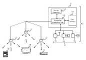
- FIG. 1is a schematic diagram illustrating an infrastructure of a remote controlling system 1 according to the preferred embodiment of the invention.
- the remote controlling system 1is used for controlling N electronic equipments 2 a - 2 c within a situation, and N is a natural number.
- Each of the N electronic equipments 2 a - 2 cincludes a respective radiation-based signal receiver (not shown) and is operated in accordance with a respective set of first instructions.
- the remote controlling system 1includes at least one radiation-based signal transmitter 12 and a processing/controlling apparatus 14 .
- the processing/controlling apparatus 14includes a storage device 142 , a user interface 144 , and a processing/controlling unit 146 .
- the radiation-based signal transmitters 12are distributed in the situation for covering N radiation-based signal receivers in communication.
- the storage device 142stores a look-up table recording M commands and M sets of second instructions; each set of second instructions corresponds to one of the M commands, wherein M is natural number.
- the user interface 144enables a user to directly input one of the commands.
- the processing/controlling unit 146is electrically connected to the at least one radiation-based signal transmitter 12 , the storage device 142 , and the user interface 144 , respectively; the processing/controlling unit 146 receives the inputted command, accesses the set of second instructions corresponding to the received command, and controls the at least one radiation-based signal transmitter 12 to emit a set of radiation-based signals which represent the set of second instructions corresponding to the received command.
- the processing/controlling apparatus 14can be executed as a computer and can be disposed with a touch panel for users to conveniently operate the user interface 144 .
- FIG. 2is an example of the look-up table stored in the storage device 142 .
- the look-up table shown in FIG. 2not only has a command column and an instruction column but also a description column for users to conveniently edit.
- the user interface 144also enables the user to edit the commands and the instructions stored in the storage device 142 .
- one of the N electronic equipments 2 a - 2 creceives, via the radiation-based signal receiver thereof, the emitted radiation-based signals, converts the received radiation-based signals into the set of second instructions, and judges if one or more of the sets of second instructions match the respective set of first instructions; if there is any, it operates in accordance with the matched first instructions.
- the situationcan be a home, a classroom, an office, a factory, an exhibition . . . etc.
- the remote controlling system 1can additionally include at least one communication device for linking an external communication network, such as a radio telecommunication module 16 a , a public switched telephone module 16 b , and a network module 16 c . . . etc.
- an external communication networksuch as a radio telecommunication module 16 a , a public switched telephone module 16 b , and a network module 16 c . . . etc.
- the radio telecommunication module 16 acan link to a radio telecommunication network.
- the public switched telephone module 16 bcan link to a public switched telephone network.
- the network module 16 ccan link to a local area network, an intranet, an internet . . . etc.
- each of the emitted radiation-based signalsis an infrared
- each of the radiation-based signal receiversis an infrared receiver
- each of the at least one radiation-based signal transmitter 12is an infrared transmitter.
- the at least one radiation-based signal transmitter 12 and extra communication modulescan be advisably cascaded by cables (such as RS485 cable), and they are able to serve as hot-swappable and general plugs (such as USB plug) of computer interface.
- the look-up table and the user interface 144can serve as storing medium such as compact disks.
Landscapes
- Physics & Mathematics (AREA)
- General Physics & Mathematics (AREA)
- Engineering & Computer Science (AREA)
- Automation & Control Theory (AREA)
- Selective Calling Equipment (AREA)
- Telephonic Communication Services (AREA)
Abstract
Description
Claims (5)
Applications Claiming Priority (3)
| Application Number | Priority Date | Filing Date | Title |
|---|---|---|---|
| TW095132482ATWI328936B (en) | 2006-09-01 | 2006-09-01 | Remote controlling system for controlling electronic equipments within situation |
| TW95132482A | 2006-09-01 | ||
| TW095132482 | 2006-09-01 |
Publications (2)
| Publication Number | Publication Date |
|---|---|
| US20080084280A1 US20080084280A1 (en) | 2008-04-10 |
| US8310348B2true US8310348B2 (en) | 2012-11-13 |
Family
ID=39274538
Family Applications (1)
| Application Number | Title | Priority Date | Filing Date |
|---|---|---|---|
| US11/594,181Expired - Fee RelatedUS8310348B2 (en) | 2006-09-01 | 2006-11-08 | Remote controlling system for controlling electronic equipments within situation |
Country Status (2)
| Country | Link |
|---|---|
| US (1) | US8310348B2 (en) |
| TW (1) | TWI328936B (en) |
Cited By (5)
| Publication number | Priority date | Publication date | Assignee | Title |
|---|---|---|---|---|
| US20120019400A1 (en)* | 2010-07-23 | 2012-01-26 | Patel Mukesh K | Multi-function remote control device |
| US20140203919A1 (en)* | 2013-01-24 | 2014-07-24 | L & P Property Management Company | Wireless two-way communication protocol for automated furniture accessory integration |
| US20160063853A1 (en)* | 2014-08-26 | 2016-03-03 | Tsung-Hsiang Mi | Personalized home situation control system and personalized home situation control method |
| US9514637B2 (en) | 2013-01-24 | 2016-12-06 | L & P Property Management Company | Wireless two-way communication protocol for automated furniture accessory integration |
| US11544976B2 (en)* | 2015-04-01 | 2023-01-03 | Urban SKY, LLC | Smart building system for integrating and automating property management and resident services in multi-dwelling unit buildings |
Families Citing this family (2)
| Publication number | Priority date | Publication date | Assignee | Title |
|---|---|---|---|---|
| TWI407276B (en) | 2010-12-28 | 2013-09-01 | Ind Tech Res Inst | Method and apparatus for monitoring and controlling household appliances standby state |
| CN105045123A (en)* | 2015-06-29 | 2015-11-11 | 广西大学 | Remote household intelligent control system |
Citations (15)
| Publication number | Priority date | Publication date | Assignee | Title |
|---|---|---|---|---|
| US5631652A (en)* | 1994-05-10 | 1997-05-20 | Samsung Electronics Co., Ltd. | Remote control method and system using one remote controller to control more than one apparatus |
| US5963624A (en)* | 1997-12-05 | 1999-10-05 | Zilog, Inc. | Digital cordless telephone with remote control feature |
| US6469633B1 (en)* | 1997-01-06 | 2002-10-22 | Openglobe Inc. | Remote control of electronic devices |
| US20030195969A1 (en)* | 2002-04-04 | 2003-10-16 | Neuman Darren D. | System and method supporting infrared remote control over a network |
| US6694125B2 (en)* | 1998-05-04 | 2004-02-17 | Skyworks Solutions, Inc. | System and method for extending the range of a base unit |
| US6731201B1 (en)* | 2000-02-23 | 2004-05-04 | Robert Shaw Controls Company | Communications module and system |
| US6748278B1 (en)* | 2000-03-13 | 2004-06-08 | Microsoft Corporation | Remote controlled system with computer-based remote control facilitator |
| US6774813B2 (en)* | 2001-03-30 | 2004-08-10 | Koninklijke Philips Electronics N.V. | System and method for interleaving infrared command codes with identifier codes |
| TW200501662A (en) | 2003-06-24 | 2005-01-01 | Touch Sense Corp | System capable of proceeding remote control over electric appliance and acquisition of its status |
| US6891838B1 (en)* | 1998-06-22 | 2005-05-10 | Statsignal Ipc, Llc | System and method for monitoring and controlling residential devices |
| TW200522555A (en) | 2003-12-31 | 2005-07-01 | Inventec Corp | Universal-remote control device with the function of customized prompting |
| US6930661B2 (en)* | 2000-07-17 | 2005-08-16 | Sony Corporation | Bi-directional communication system, display apparatus, base apparatus and bi-directional communication method |
| US6998955B2 (en)* | 2002-08-09 | 2006-02-14 | Ballew Michael A | Virtual electronic remote control device |
| US7631062B2 (en)* | 2001-08-06 | 2009-12-08 | Ricoh Company, Ltd. | System, computer program product and method for managing and controlling a local network of electronic devices |
| US8232861B2 (en)* | 2004-11-18 | 2012-07-31 | Watonga Technology, Inc. | Remote controller capable of selectively controlling a plurality of electric appliances, remote control system and method thereof |
- 2006
- 2006-09-01TWTW095132482Apatent/TWI328936B/ennot_activeIP Right Cessation
- 2006-11-08USUS11/594,181patent/US8310348B2/ennot_activeExpired - Fee Related
Patent Citations (15)
| Publication number | Priority date | Publication date | Assignee | Title |
|---|---|---|---|---|
| US5631652A (en)* | 1994-05-10 | 1997-05-20 | Samsung Electronics Co., Ltd. | Remote control method and system using one remote controller to control more than one apparatus |
| US6469633B1 (en)* | 1997-01-06 | 2002-10-22 | Openglobe Inc. | Remote control of electronic devices |
| US5963624A (en)* | 1997-12-05 | 1999-10-05 | Zilog, Inc. | Digital cordless telephone with remote control feature |
| US6694125B2 (en)* | 1998-05-04 | 2004-02-17 | Skyworks Solutions, Inc. | System and method for extending the range of a base unit |
| US6891838B1 (en)* | 1998-06-22 | 2005-05-10 | Statsignal Ipc, Llc | System and method for monitoring and controlling residential devices |
| US6731201B1 (en)* | 2000-02-23 | 2004-05-04 | Robert Shaw Controls Company | Communications module and system |
| US6748278B1 (en)* | 2000-03-13 | 2004-06-08 | Microsoft Corporation | Remote controlled system with computer-based remote control facilitator |
| US6930661B2 (en)* | 2000-07-17 | 2005-08-16 | Sony Corporation | Bi-directional communication system, display apparatus, base apparatus and bi-directional communication method |
| US6774813B2 (en)* | 2001-03-30 | 2004-08-10 | Koninklijke Philips Electronics N.V. | System and method for interleaving infrared command codes with identifier codes |
| US7631062B2 (en)* | 2001-08-06 | 2009-12-08 | Ricoh Company, Ltd. | System, computer program product and method for managing and controlling a local network of electronic devices |
| US20030195969A1 (en)* | 2002-04-04 | 2003-10-16 | Neuman Darren D. | System and method supporting infrared remote control over a network |
| US6998955B2 (en)* | 2002-08-09 | 2006-02-14 | Ballew Michael A | Virtual electronic remote control device |
| TW200501662A (en) | 2003-06-24 | 2005-01-01 | Touch Sense Corp | System capable of proceeding remote control over electric appliance and acquisition of its status |
| TW200522555A (en) | 2003-12-31 | 2005-07-01 | Inventec Corp | Universal-remote control device with the function of customized prompting |
| US8232861B2 (en)* | 2004-11-18 | 2012-07-31 | Watonga Technology, Inc. | Remote controller capable of selectively controlling a plurality of electric appliances, remote control system and method thereof |
Cited By (13)
| Publication number | Priority date | Publication date | Assignee | Title |
|---|---|---|---|---|
| US9424738B2 (en)* | 2010-07-23 | 2016-08-23 | Tivo Inc. | Automatic updates to a remote control device |
| US20120178371A1 (en)* | 2010-07-23 | 2012-07-12 | Mukesh Patel | Automatic updates to a remote control device |
| US9076322B2 (en) | 2010-07-23 | 2015-07-07 | Tivo Inc. | Determining commands based on detected movements of a remote control device |
| US20120019400A1 (en)* | 2010-07-23 | 2012-01-26 | Patel Mukesh K | Multi-function remote control device |
| US20160358461A1 (en)* | 2010-07-23 | 2016-12-08 | Tivo Inc. | Automatic updates to a remote control device |
| US9685072B2 (en) | 2010-07-23 | 2017-06-20 | Tivo Solutions Inc. | Privacy level indicator |
| US9691273B2 (en)* | 2010-07-23 | 2017-06-27 | Tivo Solutions Inc. | Automatic updates to a remote control device |
| US9786159B2 (en)* | 2010-07-23 | 2017-10-10 | Tivo Solutions Inc. | Multi-function remote control device |
| US20140203919A1 (en)* | 2013-01-24 | 2014-07-24 | L & P Property Management Company | Wireless two-way communication protocol for automated furniture accessory integration |
| US9412262B2 (en)* | 2013-01-24 | 2016-08-09 | L&P Property Management Company | Wireless two-way communication protocol for automated furniture accessory integration |
| US9514637B2 (en) | 2013-01-24 | 2016-12-06 | L & P Property Management Company | Wireless two-way communication protocol for automated furniture accessory integration |
| US20160063853A1 (en)* | 2014-08-26 | 2016-03-03 | Tsung-Hsiang Mi | Personalized home situation control system and personalized home situation control method |
| US11544976B2 (en)* | 2015-04-01 | 2023-01-03 | Urban SKY, LLC | Smart building system for integrating and automating property management and resident services in multi-dwelling unit buildings |
Also Published As
| Publication number | Publication date |
|---|---|
| TW200814555A (en) | 2008-03-16 |
| TWI328936B (en) | 2010-08-11 |
| US20080084280A1 (en) | 2008-04-10 |
Similar Documents
| Publication | Publication Date | Title |
|---|---|---|
| US8310348B2 (en) | Remote controlling system for controlling electronic equipments within situation | |
| US20090136231A1 (en) | Remote controlling system and gateway apparatus for controlling electronic appliances within space | |
| EP0549128B1 (en) | Appliance control system providing out-of-context usage | |
| CN102662380B (en) | Concentrative networking control method and system for family electric appliances | |
| CN102231229B (en) | Multifunctional remote controller and control system applying same | |
| CN102495614A (en) | Intelligent household control system | |
| EP1665746A1 (en) | Communications, command, and control system with plug-and-play connectivity | |
| CN102117646B (en) | Multimedia player with remote control function and method thereof | |
| CN101067900A (en) | Unified remote control system and its implementation method | |
| CN104157115A (en) | Cloud service based networked all-purpose remote control device and method | |
| CN105469573A (en) | Cloud smart controller APP and key value learning and assignment method | |
| CN102737489A (en) | Remote controller, remote controlling system, and controlling method based on remote controlling system | |
| CN202796004U (en) | Light-emitting diode (LED) display screen controller | |
| CN103123752A (en) | Audio-video playing system and method based on electronic whiteboard | |
| US20080007403A1 (en) | Home security system intergrating local wireless network and external communication networks | |
| CN101039362A (en) | Method for control household appliance using fixing telephone set | |
| CN202889394U (en) | Universal intelligent remote control device | |
| CN200986741Y (en) | Remote control system | |
| CN104426987A (en) | Intelligent home furnishing management and control system based on network instructions | |
| CN202331846U (en) | Audio and video playing system based on electronic whiteboard | |
| CN201063723Y (en) | Central box for connecting signal source and play equipment | |
| CN101127607A (en) | Network adapter | |
| CN101309094A (en) | Infrared remote controller structure with built-in Bluetooth wireless transmission | |
| CN103595786A (en) | Electronic device monitoring method and electronic devices | |
| CN101465047B (en) | Intelligent remote controller and control method thereof |
Legal Events
| Date | Code | Title | Description |
|---|---|---|---|
| AS | Assignment | Owner name:LIVE EXPERIMENT DESIGN CORPORATION, TAIWAN Free format text:ASSIGNMENT OF ASSIGNORS INTEREST;ASSIGNOR:FANG, JUI-KUANG;REEL/FRAME:018538/0001 Effective date:20060930 | |
| ZAAA | Notice of allowance and fees due | Free format text:ORIGINAL CODE: NOA | |
| ZAAB | Notice of allowance mailed | Free format text:ORIGINAL CODE: MN/=. | |
| AS | Assignment | Owner name:LIVINGLAB DEVELOPMENT CO., LTD., TAIWAN Free format text:CHANGE OF NAME;ASSIGNOR:LIVE EXPERIMENT DESIGN CORPORATION;REEL/FRAME:029067/0850 Effective date:20110412 | |
| STCF | Information on status: patent grant | Free format text:PATENTED CASE | |
| FPAY | Fee payment | Year of fee payment:4 | |
| MAFP | Maintenance fee payment | Free format text:PAYMENT OF MAINTENANCE FEE, 8TH YR, SMALL ENTITY (ORIGINAL EVENT CODE: M2552); ENTITY STATUS OF PATENT OWNER: SMALL ENTITY Year of fee payment:8 | |
| LAPS | Lapse for failure to pay maintenance fees | Free format text:PATENT EXPIRED FOR FAILURE TO PAY MAINTENANCE FEES (ORIGINAL EVENT CODE: EXP.); ENTITY STATUS OF PATENT OWNER: SMALL ENTITY | |
| STCH | Information on status: patent discontinuation | Free format text:PATENT EXPIRED DUE TO NONPAYMENT OF MAINTENANCE FEES UNDER 37 CFR 1.362 | |
| FP | Lapsed due to failure to pay maintenance fee | Effective date:20241113 |