US8310101B2 - Grid synchronisation - Google Patents
Grid synchronisationDownload PDFInfo
- Publication number
- US8310101B2 US8310101B2US12/809,436US80943608AUS8310101B2US 8310101 B2US8310101 B2US 8310101B2US 80943608 AUS80943608 AUS 80943608AUS 8310101 B2US8310101 B2US 8310101B2
- Authority
- US
- United States
- Prior art keywords
- grid
- inverter
- output
- renewable energy
- mains
- Prior art date
- Legal status (The legal status is an assumption and is not a legal conclusion. Google has not performed a legal analysis and makes no representation as to the accuracy of the status listed.)
- Active
Links
Images


Classifications
- H—ELECTRICITY
- H02—GENERATION; CONVERSION OR DISTRIBUTION OF ELECTRIC POWER
- H02J—CIRCUIT ARRANGEMENTS OR SYSTEMS FOR SUPPLYING OR DISTRIBUTING ELECTRIC POWER; SYSTEMS FOR STORING ELECTRIC ENERGY
- H02J3/00—Circuit arrangements for AC mains or AC distribution networks
- H02J3/38—Arrangements for parallely feeding a single network by two or more generators, converters or transformers
- H02J3/46—Controlling of the sharing of output between the generators, converters, or transformers
- H—ELECTRICITY
- H02—GENERATION; CONVERSION OR DISTRIBUTION OF ELECTRIC POWER
- H02J—CIRCUIT ARRANGEMENTS OR SYSTEMS FOR SUPPLYING OR DISTRIBUTING ELECTRIC POWER; SYSTEMS FOR STORING ELECTRIC ENERGY
- H02J3/00—Circuit arrangements for AC mains or AC distribution networks
- H02J3/38—Arrangements for parallely feeding a single network by two or more generators, converters or transformers
- H02J3/40—Synchronising a generator for connection to a network or to another generator
- H—ELECTRICITY
- H02—GENERATION; CONVERSION OR DISTRIBUTION OF ELECTRIC POWER
- H02J—CIRCUIT ARRANGEMENTS OR SYSTEMS FOR SUPPLYING OR DISTRIBUTING ELECTRIC POWER; SYSTEMS FOR STORING ELECTRIC ENERGY
- H02J3/00—Circuit arrangements for AC mains or AC distribution networks
- H02J3/38—Arrangements for parallely feeding a single network by two or more generators, converters or transformers
- H02J3/46—Controlling of the sharing of output between the generators, converters, or transformers
- H02J3/48—Controlling the sharing of the in-phase component
- H—ELECTRICITY
- H02—GENERATION; CONVERSION OR DISTRIBUTION OF ELECTRIC POWER
- H02J—CIRCUIT ARRANGEMENTS OR SYSTEMS FOR SUPPLYING OR DISTRIBUTING ELECTRIC POWER; SYSTEMS FOR STORING ELECTRIC ENERGY
- H02J3/00—Circuit arrangements for AC mains or AC distribution networks
- H02J3/38—Arrangements for parallely feeding a single network by two or more generators, converters or transformers
- H02J3/46—Controlling of the sharing of output between the generators, converters, or transformers
- H02J3/50—Controlling the sharing of the out-of-phase component
- H—ELECTRICITY
- H02—GENERATION; CONVERSION OR DISTRIBUTION OF ELECTRIC POWER
- H02J—CIRCUIT ARRANGEMENTS OR SYSTEMS FOR SUPPLYING OR DISTRIBUTING ELECTRIC POWER; SYSTEMS FOR STORING ELECTRIC ENERGY
- H02J2300/00—Systems for supplying or distributing electric power characterised by decentralized, dispersed, or local generation
- H02J2300/20—The dispersed energy generation being of renewable origin
- H02J2300/22—The renewable source being solar energy
- H02J2300/24—The renewable source being solar energy of photovoltaic origin
- H—ELECTRICITY
- H02—GENERATION; CONVERSION OR DISTRIBUTION OF ELECTRIC POWER
- H02J—CIRCUIT ARRANGEMENTS OR SYSTEMS FOR SUPPLYING OR DISTRIBUTING ELECTRIC POWER; SYSTEMS FOR STORING ELECTRIC ENERGY
- H02J3/00—Circuit arrangements for AC mains or AC distribution networks
- H02J3/38—Arrangements for parallely feeding a single network by two or more generators, converters or transformers
- H02J3/381—Dispersed generators
- H—ELECTRICITY
- H02—GENERATION; CONVERSION OR DISTRIBUTION OF ELECTRIC POWER
- H02J—CIRCUIT ARRANGEMENTS OR SYSTEMS FOR SUPPLYING OR DISTRIBUTING ELECTRIC POWER; SYSTEMS FOR STORING ELECTRIC ENERGY
- H02J3/00—Circuit arrangements for AC mains or AC distribution networks
- H02J3/38—Arrangements for parallely feeding a single network by two or more generators, converters or transformers
- H02J3/388—Islanding, i.e. disconnection of local power supply from the network
- Y—GENERAL TAGGING OF NEW TECHNOLOGICAL DEVELOPMENTS; GENERAL TAGGING OF CROSS-SECTIONAL TECHNOLOGIES SPANNING OVER SEVERAL SECTIONS OF THE IPC; TECHNICAL SUBJECTS COVERED BY FORMER USPC CROSS-REFERENCE ART COLLECTIONS [XRACs] AND DIGESTS
- Y02—TECHNOLOGIES OR APPLICATIONS FOR MITIGATION OR ADAPTATION AGAINST CLIMATE CHANGE
- Y02E—REDUCTION OF GREENHOUSE GAS [GHG] EMISSIONS, RELATED TO ENERGY GENERATION, TRANSMISSION OR DISTRIBUTION
- Y02E10/00—Energy generation through renewable energy sources
- Y02E10/50—Photovoltaic [PV] energy
- Y02E10/56—Power conversion systems, e.g. maximum power point trackers
Definitions
- the inventionrelates to power generation, and in particular to a grid synchroniser for connecting an AC output of a power converter to the AC grid mains.
- the inventionalso relates to driver circuits, in particular for power semiconductor switching devices of the type that are employed in ac (alternating current) inverters. More particularly aspects of the invention relate to techniques for rapid removal of charge from a control terminal of a power switching device such as a MOSFET (Metal Oxide Semiconductor Field Effect Transistor) IGBT (Insulated Gate Bipolar Transistor) or Thyristor.
- MOSFETMetal Oxide Semiconductor Field Effect Transistor
- IGBTInsulated Gate Bipolar Transistor
- micropower generation systemssuch as those in the home, typically comprise one or more of a number of solar cells (e.g. on the roof), wind turbines, combined heat and power systems and other like systems.
- the micropower generatorsgenerate electricity for the home, and the power is converted into useable voltage and current suitable for the home, for example 240V at 50 Hz or 110V at 60 Hz.
- more power than is actually required by the homeis sometimes generated. If the micropower generation system were connected to the AC grid, from which power is normally drawn in conventional homes, this surplus power could be sent back to the AC grid.
- Invertersare often used to generate an AC output from a DC input.
- the invertersare generally located within the proximity of the power source (solar cells, wind turbine etc). The point at which the inverter is connected to the AC grid mains is often remote from its physical location.
- Inverters connected to the grid remotelymay experience a phase shifted line voltage due to line impedance and therefore transfer an increased amount of reactive power in the network.
- the increase in reactive powerimplies minimised system efficiency.
- a grid synchroniserto synchronise an AC output of an inverter to an AC grid mains, said inverter having a power input and an AC output for connection to said AC grid mains to provide a power supply input into said AC grid mains
- the grid synchronisercomprising: an inverter controller to control said AC output of said inverter, said controller including a receiver to receive grid data from a grid sensor location remote from said inverter, said grid sensor sensing a grid characteristic of said AC grid mains, wherein said grid data comprises data relating to a grid characteristic of said AC grid mains sensed by a grid sensor, and wherein said inverter controller controls said AC output responsive to said grid data relating to said grid characteristic.
- said sensed grid characteristiccomprises a phase of said AC grid mains.
- the communication of the sensed grid characteristics of the AC grid mains(for example the phase of the current and/or voltage), enables the inverter to be controlled in order that its AC output is synchronised with that of the AC grid mains, irrespective of the line load between the inverter and the grid connection.
- said receiveris in wired communication with a grid sensor.
- said wired communicationis through a power supply line.
- said receiveris in wireless communication with a grid sensor.
- the grid synchroniserfurther comprises an inverter sensor to sense an inverter characteristic of said AC output of said inverter and to transmit inverter data relating to said sensed inverter characteristic to a grid sensor located remote from said inverter.
- said sensed inverter characteristiccomprises one or more of a phase of said AC output of said inverter, a power output or a power efficiency of said inverter.
- the present inventionalso provides a method of synchronising an AC output of an inverter to an AC grid mains, said inverter having a power input and an AC output for connection to said AC grid mains to provide a power supply input into said AC grid mains, the method comprising: sensing a characteristic of said AC grid mains using a grid sensor located remote from said inverter; transmitting grid data relating to said sensed grid characteristic to said inverter; and controlling said AC output of said inverter responsive to said grid data relating to said sensed grid characteristic.
- said sensed grid characteristiccomprises a phase of said AC grid mains.
- Sensing and transmitting the sensed grid characteristics of the AC grid mainsenables the inverter to be controlled in order that its AC output is synchronised with that of the AC grid mains, irrespective of the line load between the inverter and the grid connection.
- the methodfurther comprises sensing a characteristic of said AC output of said inverter; and transmitting inverter data relating to said sensed inverter characteristic to said grid sensor.
- said sensed inverter characteristiccomprises one or more of a phase of said AC output of said inverter, a power output or a power efficiency of said inverter.
- the present inventionalso provides a system for micropower generation, the system comprising: an inverter having a power input and an AC output for connection to an AC grid mains to provide a power supply input into said AC grid mains; a sensor, remote from said inverter, to sense a grid characteristic of said AC grid mains and to transmit data relating to said sensed grid characteristic to said inverter, wherein said inverter includes a receiver to receive said transmitted data, said inverter being configured to control said AC output responsive to said data relating to said sensed grid characteristic.
- said sensed grid characteristiccomprises a phase of said AC grid mains.
- the communication of the sensed grid characteristics of the AC grid mains(for example the phase of the current and/or voltage), enables the inverter to be controlled in order that its AC output is synchronised with that of the AC grid mains, irrespective of the line load between the inverter and the grid connection.
- said sensoris configured to couple to said AC grid mains at a point where said AC output from said inverter is injected into said AC grid mains.
- the systemcomprising a plurality of said inverters each inputting power into said AC grid mains at substantially the same point.
- the systemfurther comprises: an inverter sensor to sense an inverter characteristic of said AC output of said inverter and to transmit inverter data relating to said sensed inverter characteristic to a grid sensor located remote from said inverter.
- said sensed inverter characteristiccomprises one or more of a phase of said AC output of said inverter, a power output or a power efficiency of said inverter.
- a driver circuitfor switching on and off a semiconductor switching device connected to an alternating current (ac) power supply, said semiconductor switching device having first and second terminals, and a switching control terminal to control switching between said first and second terminals, the driver circuit being configured to derive from said ac power supply a control signal for application to said switching control terminal of said semiconductor switching device to control said switching, said driver circuit comprising: an input to receive a voltage derived from said ac power supply; a reference line for coupling to one of said first and second terminals of said semiconductor switching device; a rectifier having an input coupled to said input and an output; and a resistive element coupled between said output of said rectifier and said reference line; and a drive output for driving said switching control terminal of said semiconductor switching device, said drive output being coupled to a circuit node between said resistive element and said output of said rectifier.
- acalternating current
- the resistive elementcomprises a resistor although the skilled person will appreciate that an FET may also be used as a resistive element.
- Preferred embodiments of the circuitinclude a voltage limiting element such as zener diode coupled between the circuit node and the reference line. This is particularly important when driving grid mains.
- Preferred embodimentsalso include a potential divider coupled to the input, the rectifier being coupled to an output of the potential divider.
- the resistive element described abovehas a resistance of less than 1 ⁇ 5, more preferably less than 1/10 or less than 1/20 of a resistance value of an arm of the potential divider.
- the semiconductor switching devicecomprises a MOSFET, IGBT, or Thyristor, more particularly a power device (that is a device with an operating or switching voltage capability of greater than 100 volts and/or a power rating of greater 1 watt).
- the ac power supplycomprises a grid mains power supply and the semiconductor switching device has a breakdown voltage of at least 100 volts.
- the grid mains power supplymay either be a domestic mains power supply such as a 110 volt or 230 volt power supply or a three phase power supply, typically operating at 415 volts.
- the inventionfurther provides a full-bridge or half-bridge rectifier circuit including one or more semiconductor switching devices and respective driver circuits as described above.
- the inventionfurther provides a power conditioning circuit with a dc input and an ac output for connection to an ac grid mains power supply.
- the embodiments of the above-described driver circuitmay be employed to drive a semiconductor switching device chopping a power supply derived from the dc input to provide an ac output to the grid mains supply.
- Some preferred embodiments of such a power conditioning circuithave two semiconductor switching devices driven by respective driver circuits, switching in alternate half cycles of the ac grid mains power supply.
- driver circuits and switching devices as described abovemay be employed as one or more switches in a dc-to-ac power converter of a type described below:
- a dc-to-ac power converterincluding a transformer having a primary and a secondary winding, the primary winding of said transformer being coupled to a dc input of said power converter and the secondary winding of said transformer being coupled to an ac output of said converter, and wherein the converter further comprises: a first pair of switches on said primary side of said converter, coupled between said dc input and said primary winding, to convert a dc supply from said dc input to an ac current for driving said transformer; a second pair of switches on said secondary side of said converter coupled between said secondary winding and said ac output, one in a forward path to said ac output and one in a return path from said ac output; a diode coupled across each of said secondary side switches; and a controller configured to control said primary and secondary side switches to convert a dc supply at said dc input to an ac supply at said ac output.
- a DC-to-AC power converterincluding a transformer having a primary and a secondary winding, the primary winding of the transformer being coupled to a dc input of the power converter and the secondary winding of the transformer being coupled to an ac output of the converter, and wherein: a first and second switch connected to the primary winding of the transformer to convert a dc supply from the dc input to an ac current for driving the transformer; a first and second switch connected to the secondary winding of the transformer such that the first switch is in a forward path to the ac output and the second switch is in a return path to the ac output; a first and second diode coupled across the respective first and second switches connected to the secondary winding; and wherein the first switch connected to the primary winding of the transformer is controlled to provide a first half cycle of an ac voltage to the primary winding of the transformer; the second switch connected to the primary winding of the transformer is controlled to provide a second half cycle of an ac voltage to the primary winding of the primary wind
- a method of removing control terminal charge from a power semiconductor switching devicecomprising supplying a drive signal to said control terminal of said power semiconductor switching device via a rectifier, and leaking current from said control terminal to a reference line whilst said power switching device is turned on.
- the power semiconductor switching devicecomprises a MOSFET, IGBT or Thyristor; in embodiments the reference line comprises a ground line.
- FIG. 1shows a typical setup of an inverter connected to the AC grid mains
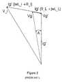
- FIG. 2shows the phasor diagram of the relationship between Vg and Vg′
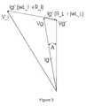
- FIG. 3illustrates a system with multiple inverters
- FIG. 4shows the system according to the present invention
- FIG. 5shows the resulting desirable phasor relationship between the grid voltage and the inverter current for a single inverter network
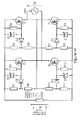
- FIG. 6shows a system of multiple inverters connected to the grid according to the present invention
- FIG. 7shows a circuit diagram of a driver circuit according to an embodiment of the invention.
- FIG. 8shows a circuit diagram of a driver circuit omitting a rectifier, illustrating operation of the circuit of FIG. 7 ;
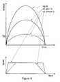
- FIG. 9shows graphs of effective input voltage to the driver circuit over a half-cycle of ac grid mains for circuits with and without a rectifier and lacking a zener diode (upper) and with a zener diode (lower);
- FIG. 10shows, schematically, leakage capacitances of a MOSFET
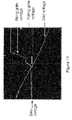
- FIG. 11shows measured waveforms from a circuit similar to that illustrated in FIG. 8 ;
- FIG. 12shows waveforms from circuits similar to that illustrated in FIG. 7 ;
- FIG. 13shows a circuit of a dc-to-ac power converter comprising four switches (two on a transformer primary side, two on a transformer secondary side) incorporating secondary-side driver circuits according to an embodiment of the invention
- FIG. 14illustrates an example of a full-bridge rectifier circuit incorporating switching devices with switching controlled by an ac grid mains supply to which the circuit is connected, for either receiving power from a mains supply and delivering power to a load or for receiving a dc power input and providing an ac power output to a mains supply;
- FIG. 15shows waveforms illustrating the operation of FIG. 14 .
- FIG. 1shows a typical setup of an inverter connected to the AC grid mains.
- the line connecting an inverter to the gridhas both inductance L_L and dc resistance R_L associated with it and whose combined effect form line impedance Z_L.
- the line impedanceis dependent on the length of the cable and the conductivity of the material. Due to the line impedance, the phase and magnitude of the grid voltage Vg differs from the phase and magnitude of the voltage Vg′ that the inverter detects at its terminals. The difference between Vg and Vg′ are dependent on the value of Z_L. For inverters connected to the grid and situated remotely such as on rooftop the impedance Z_L may be significant. The effect of this is that the inverter transfers current in phase with Vg′ and not Vg.
- FIG. 2shows the phasor diagram of the relationship between Vg and Vg′, the inverter internal voltage V_i used to control current injection and the inverter output current Ig′.
- L_i and R_irepresent the inverter internal impedance though which power is transferred onto the grid.
- Vg′Vg ⁇ Ig ′( jwL — L+R — L ) 1
- the angle Arepresents the difference in phase between Vg and Vg′.
- the result of this phase differenceis the transfer of reactive power between inverter and the grid. Reactive power is not converted into useful power but lost through parasitic resistance on the network. As a consequence the system efficiency is reduced.
- FIG. 3illustrates a system with multiple inverters.
- Vg 3′Vg ⁇ ( Ig 1′+ Ig 2′+ Ig 3′) Z — L ⁇ Ig 3′ Z — 3 2
- Vg 2′Vg ⁇ ( Ig 1′+ Ig 2′+ Ig 3′) Z — L ⁇ ( Ig 1′+ Ig 2′) Z — 4 ⁇ Ig 2′ Z — 2 3
- Vg 1′Vg ⁇ ( Ig 1′+ Ig 2′+ Ig 3′) Z — L ⁇ ( Ig 1′+ Ig 2′) Z — 4 ⁇ Ig 1′ Z — 1 4
- the three inverters in FIG. 3all experience different values of grid voltage, Vg 1 ′, Vg 2 ′ and Vg 3 ′, due to the impedance in the line.
- the currents Ig 1 ′, Ig 2 ′ and Ig 3 ′are generated by inverters 1 , 2 and 3 respectively.
- the currentsare assumed to be in phase with the corresponding inverter voltages.
- Equations 2, 3 and 4show the relationships between each of the inverter voltages and the grid voltage.
- FIG. 4shows the proposed solution to the problem of reactive power transfer.
- a grid sensorlocated at, or substantially near to the point at which power from the converter is injected onto the AC grid mains, is used to detect a number of characteristics of the AC grid mains, for example the current and/or grid voltage phases and frequency. This information is then communicated to the inverter, which is then used to control the current phase of the inverter such that the output current of the inverter is substantially synchronised to (i.e. in phase with) the voltage Vg.
- the communication of the sensed characteristics of the AC grid mainsnamely the phase of the current and/or voltage, enables the inverter to be controlled in order that its AC output is synchronised with that of the AC grid mains.
- the object of controlis the line current Ig flowing into the grid. The current is detected at the terminals of the grid supply and is therefore corrected from the effects of impedance on the system.
- FIG. 5shows the resulting desirable phasor relationship between the grid voltage and the inverter current for a single inverter network.
- the communication systemcan be implemented either with the employment of a wireless network or a wired network.
- a wireless networklow rate data may be sent down the power lines throughout the house ring main.
- a radio protocolsuch as ZigBee, may be employed to communicate the data between the sensor and the inverter.
- the grid sensorcould be remote or local to the inverter. However, the grid sensor is preferably located at, or substantially near the point at which power from the output of the inverter is injected into the AC grid mains, for example at the house's switchboard. The sensor may be integrated into the switchboard in order to acquire phase and magnitude information of the grid current and voltage.
- FIG. 6shows a system of multiple inverters connected to the grid, and using the system of the present invention.
- the AC outputs of each of the inverters in the systemcan be synchronised to Vg regardless of the line impedance.
- each of the invertershas a receiver (here shown as a wireless receiver; the skilled reader would understand that a wired connection could be used instead) for receiving data from a single grid sensor located at, or substantially near to the point at which power generated from the inverters is injected into the AC grid mains.
- Each of the invertersis controlled in response to the data provided by the single grid sensor.
- additional datamay also be captured at the inverter, such as the output voltage and/or current, the DC or AC power input, the AC output, the efficiency of the inverter and other such data.
- the systemcould transmit such data from the inverter over the wired or wireless link back to the grid sensor.
- datawould, for example, enable the grid sensor to detect if one or more of the inverters was malfunctioning, and to alert a user that action is required to correct such a fault.
- the grid sensor arrangementcould also collate data collected from the grid and/or the inverters and display such data to a user on a display.
- a display of datawould enable a user to visualise that power is being provided by the converter(s), the efficiency of the converts and/or how much power is being sent back to the grid at any time.
- the driver circuitaddresses the aforementioned problem associated with removing charge quickly from the gate terminal of the semiconductor device when the grid voltage changes polarity.
- the rapid removal of charge from the gate terminalenables grid connection of devices with high gate charge density that are therefore slow switching. This in turn leads to the transfer of high power densities through the switching device.
- the driver circuitcan be used in energy conversion systems such as solar photovoltaic and wind and in rectifier circuits connected to the utility grid or similar alternating current supplies.
- FIG. 7shows the circuit solution.
- the circuituses high value ohmic resistor R 1 and therefore affords low potential divider losses.
- a low value resistor R 3is used to enable rapid removal of gate charge as the grid voltage drops to zero.
- the semiconductor switch Tcan be implemented as a MOSFET device, IGBT or Thyristor.
- Vgridis zero, implying that the potential difference between points 1 and 2 in FIG. 7 is zero, and the potential difference between 2 and 5 is zero.
- the zener diode Zhas a value Vz.
- the resistors R 1 and R 2are chosen to have high value, example 1 mega ohm each.
- Vgatestays constant until V 4 drops below Vz as Vgrid drops.
- Dthe state of D when V 4 drops below Vz. If the gate charge is removed rapidly, D would remain forward biased until Vgrid becomes zero. In this case T turns off before the Vgrid reverses polarity. On the other hand if the Vgate remains higher than V 4 , D is reverse biased. In this case there is a possibility that the MOSFET is on when Vgrid reverses. If this happens in, say, a half or full-bridge rectifier, the result is a short circuit in the power circuit.
- resistor R 3is chosen to have a low value, for example 20 kilo ohm to 100 kilo ohm. This would enable the removal of charge rapidly and therefore enable high gate charge switches to be used. It is possible to have a low value of R 3 across Vgate because of the blocking diode D. If D is short-circuited (as shown in FIG. 8 , which is included to illustrate this) Vgate may not attain Vz for all or part of the half grid cycle and therefore the switch would not work properly. An example for the value of Vz that would result in normal operation of the switch is say 15V (this varies with the type of switching device). In mains driven circuits the zener diode is important. FIG. 8 illustrates a circuit with D replaced by a conducting wire.
- FIG. 9shows the resulting gate drive signals with and without the diode D connected.
- FIG. 9shows graphs of effective input voltage to the driver circuit over a half-cycle of ac grid mains for circuits with and without a rectifier and lacking a zener diode (upper) and with a zener diode (lower).
- the gate drive circuithas the ability to discharge the gate terminal of the connected switching device rapidly, therefore preventing short-circuiting the grid when the grid voltage reverses.
- Switching devicessuch as MOSFETs have parasitic gate capacitances that store charge.
- FIG. 10shows a representation of the MOSFET with drain-to-gate and gate-to-source parasitic capacitors.
- the charge stored in the combined capacitance C 1 and C 2is discharged through R 3 and through some leakage current in the MOSFET and the zener diode.
- the time constant for the discharge assuming that the diode D stays reverse biasedis given by equation 1.
- T1/( CR 3 +CRL ) were C is the overall gate capacitance and RL is the leakage resistance due to the MOSFET and zener diode. This equation also indicates that a small R 3 reduces T.
- FIG. 11shows some experimental results obtained when the gate circuit is designed without the diode D and the resistor R 3 .
- the falling gate voltageovershoots the zero-crossing point of the grid by a significant amount to cause short circuit when the other half cycle rises (see the double-ended arrow).
- FIG. 12shows the results obtained when D and R 3 are included in the design. In this case the gate signals fall rapidly enough to avoid any significant overshoot.
- the driver circuitscan be used in applications where synchronised switching of the grid is used for power transfer in either direction.
- One exampleis as used in the circuit diagram of FIG. 13 .
- the principle of operation of this circuitis described in our earlier patent application (ibid).
- the driversswitch the two IGBTs in alternate half cycles to allow power transfer from a source such as solar photovoltaic energy.
- FIG. 14shows another application of the proposed driver circuit.
- powercan be transferred from the grid to the load or the load can supply power to the grid.
- FIG. 15illustrates the waveforms appearing across the load. The amplitude difference between Vg and VL is for illustration clarity.
Landscapes
- Engineering & Computer Science (AREA)
- Power Engineering (AREA)
- Inverter Devices (AREA)
- Power Conversion In General (AREA)
Abstract
Description
Vg′=Vg−Ig′(jwL—L+R—L) 1
Vg3′=Vg−(Ig1′+Ig2′+Ig3′)Z—L−
Vg2′=Vg−(Ig1′+Ig2′+Ig3′)Z—L−(Ig1′+Ig2′)
Vg1′=Vg−(Ig1′+Ig2′+Ig3′)Z—L−(Ig1′+Ig2′)
T=1/(CR3+CRL)
were C is the overall gate capacitance and RL is the leakage resistance due to the MOSFET and zener diode. This equation also indicates that a small R3 reduces T.
Claims (18)
Applications Claiming Priority (5)
| Application Number | Priority Date | Filing Date | Title |
|---|---|---|---|
| GB0724828AGB2455755B (en) | 2007-12-20 | 2007-12-20 | Grid synchronisation |
| GB0724825AGB2455754B (en) | 2007-12-20 | 2007-12-20 | Driver circuits and techniques |
| GB0724825.5 | 2007-12-20 | ||
| GB0724828.9 | 2007-12-20 | ||
| PCT/GB2008/051216WO2009081205A2 (en) | 2007-12-20 | 2008-12-19 | Grid synchronisation |
Related Parent Applications (1)
| Application Number | Title | Priority Date | Filing Date |
|---|---|---|---|
| PCT/GB2008/051216A-371-Of-InternationalWO2009081205A2 (en) | 2007-12-20 | 2008-12-19 | Grid synchronisation |
Related Child Applications (1)
| Application Number | Title | Priority Date | Filing Date |
|---|---|---|---|
| US13/656,641ContinuationUS9997923B2 (en) | 2007-12-20 | 2012-10-19 | Grid synchronisation |
Publications (2)
| Publication Number | Publication Date |
|---|---|
| US20110049990A1 US20110049990A1 (en) | 2011-03-03 |
| US8310101B2true US8310101B2 (en) | 2012-11-13 |
Family
ID=40560294
Family Applications (4)
| Application Number | Title | Priority Date | Filing Date |
|---|---|---|---|
| US12/809,436ActiveUS8310101B2 (en) | 2007-12-20 | 2008-12-19 | Grid synchronisation |
| US13/656,641Active2031-03-28US9997923B2 (en) | 2007-12-20 | 2012-10-19 | Grid synchronisation |
| US15/961,356Active2029-03-19US10903658B2 (en) | 2007-12-20 | 2018-04-24 | Grid synchronisation |
| US17/157,771ActiveUS11303134B2 (en) | 2007-12-20 | 2021-01-25 | Grid synchronisation |
Family Applications After (3)
| Application Number | Title | Priority Date | Filing Date |
|---|---|---|---|
| US13/656,641Active2031-03-28US9997923B2 (en) | 2007-12-20 | 2012-10-19 | Grid synchronisation |
| US15/961,356Active2029-03-19US10903658B2 (en) | 2007-12-20 | 2018-04-24 | Grid synchronisation |
| US17/157,771ActiveUS11303134B2 (en) | 2007-12-20 | 2021-01-25 | Grid synchronisation |
Country Status (3)
| Country | Link |
|---|---|
| US (4) | US8310101B2 (en) |
| EP (1) | EP2235807B1 (en) |
| WO (1) | WO2009081205A2 (en) |
Cited By (55)
| Publication number | Priority date | Publication date | Assignee | Title |
|---|---|---|---|---|
| WO2014170643A1 (en) | 2013-04-16 | 2014-10-23 | Enecsys Limited | Power factor adjustment in multi-phase power system |
| US9130401B2 (en) | 2006-12-06 | 2015-09-08 | Solaredge Technologies Ltd. | Distributed power harvesting systems using DC power sources |
| US9235228B2 (en) | 2012-03-05 | 2016-01-12 | Solaredge Technologies Ltd. | Direct current link circuit |
| US9263971B2 (en) | 2011-12-16 | 2016-02-16 | Empower Micro Systems Inc. | Distributed voltage source inverters |
| US9291696B2 (en) | 2007-12-05 | 2016-03-22 | Solaredge Technologies Ltd. | Photovoltaic system power tracking method |
| US9318974B2 (en) | 2014-03-26 | 2016-04-19 | Solaredge Technologies Ltd. | Multi-level inverter with flying capacitor topology |
| US9362743B2 (en) | 2008-05-05 | 2016-06-07 | Solaredge Technologies Ltd. | Direct current power combiner |
| US9368964B2 (en) | 2006-12-06 | 2016-06-14 | Solaredge Technologies Ltd. | Distributed power system using direct current power sources |
| US9401599B2 (en) | 2010-12-09 | 2016-07-26 | Solaredge Technologies Ltd. | Disconnection of a string carrying direct current power |
| US9407161B2 (en) | 2007-12-05 | 2016-08-02 | Solaredge Technologies Ltd. | Parallel connected inverters |
| US9537445B2 (en) | 2008-12-04 | 2017-01-03 | Solaredge Technologies Ltd. | Testing of a photovoltaic panel |
| US9543889B2 (en) | 2006-12-06 | 2017-01-10 | Solaredge Technologies Ltd. | Distributed power harvesting systems using DC power sources |
| US9548619B2 (en) | 2013-03-14 | 2017-01-17 | Solaredge Technologies Ltd. | Method and apparatus for storing and depleting energy |
| US9590526B2 (en) | 2006-12-06 | 2017-03-07 | Solaredge Technologies Ltd. | Safety mechanisms, wake up and shutdown methods in distributed power installations |
| US9644993B2 (en) | 2006-12-06 | 2017-05-09 | Solaredge Technologies Ltd. | Monitoring of distributed power harvesting systems using DC power sources |
| US9647442B2 (en) | 2010-11-09 | 2017-05-09 | Solaredge Technologies Ltd. | Arc detection and prevention in a power generation system |
| US9673711B2 (en) | 2007-08-06 | 2017-06-06 | Solaredge Technologies Ltd. | Digital average input current control in power converter |
| US9680304B2 (en) | 2006-12-06 | 2017-06-13 | Solaredge Technologies Ltd. | Method for distributed power harvesting using DC power sources |
| US9812984B2 (en) | 2012-01-30 | 2017-11-07 | Solaredge Technologies Ltd. | Maximizing power in a photovoltaic distributed power system |
| US9819178B2 (en) | 2013-03-15 | 2017-11-14 | Solaredge Technologies Ltd. | Bypass mechanism |
| US9831824B2 (en) | 2007-12-05 | 2017-11-28 | SolareEdge Technologies Ltd. | Current sensing on a MOSFET |
| US9853538B2 (en) | 2007-12-04 | 2017-12-26 | Solaredge Technologies Ltd. | Distributed power harvesting systems using DC power sources |
| US9853565B2 (en) | 2012-01-30 | 2017-12-26 | Solaredge Technologies Ltd. | Maximized power in a photovoltaic distributed power system |
| US9866098B2 (en) | 2011-01-12 | 2018-01-09 | Solaredge Technologies Ltd. | Serially connected inverters |
| US9869701B2 (en) | 2009-05-26 | 2018-01-16 | Solaredge Technologies Ltd. | Theft detection and prevention in a power generation system |
| US9876430B2 (en) | 2008-03-24 | 2018-01-23 | Solaredge Technologies Ltd. | Zero voltage switching |
| US9923516B2 (en) | 2012-01-30 | 2018-03-20 | Solaredge Technologies Ltd. | Photovoltaic panel circuitry |
| US9941813B2 (en) | 2013-03-14 | 2018-04-10 | Solaredge Technologies Ltd. | High frequency multi-level inverter |
| US9960731B2 (en) | 2006-12-06 | 2018-05-01 | Solaredge Technologies Ltd. | Pairing of components in a direct current distributed power generation system |
| US9960667B2 (en) | 2006-12-06 | 2018-05-01 | Solaredge Technologies Ltd. | System and method for protection during inverter shutdown in distributed power installations |
| US9966766B2 (en) | 2006-12-06 | 2018-05-08 | Solaredge Technologies Ltd. | Battery power delivery module |
| US9997923B2 (en) | 2007-12-20 | 2018-06-12 | Solarcity Corporation | Grid synchronisation |
| US10115841B2 (en) | 2012-06-04 | 2018-10-30 | Solaredge Technologies Ltd. | Integrated photovoltaic panel circuitry |
| US10230310B2 (en) | 2016-04-05 | 2019-03-12 | Solaredge Technologies Ltd | Safety switch for photovoltaic systems |
| US10396662B2 (en) | 2011-09-12 | 2019-08-27 | Solaredge Technologies Ltd | Direct current link circuit |
| US10447040B2 (en) | 2014-10-15 | 2019-10-15 | Cummins Power Generation Ip, Inc. | Programmable inverter for controllable grid response |
| US10476306B2 (en) | 2014-07-15 | 2019-11-12 | Samsung Electronics Co., Ltd. | Method for control in wireless power transfer systems |
| US10673229B2 (en) | 2010-11-09 | 2020-06-02 | Solaredge Technologies Ltd. | Arc detection and prevention in a power generation system |
| US10673222B2 (en) | 2010-11-09 | 2020-06-02 | Solaredge Technologies Ltd. | Arc detection and prevention in a power generation system |
| US10931119B2 (en) | 2012-01-11 | 2021-02-23 | Solaredge Technologies Ltd. | Photovoltaic module |
| US11018623B2 (en) | 2016-04-05 | 2021-05-25 | Solaredge Technologies Ltd. | Safety switch for photovoltaic systems |
| US11177663B2 (en) | 2016-04-05 | 2021-11-16 | Solaredge Technologies Ltd. | Chain of power devices |
| US11264947B2 (en) | 2007-12-05 | 2022-03-01 | Solaredge Technologies Ltd. | Testing of a photovoltaic panel |
| US11296650B2 (en) | 2006-12-06 | 2022-04-05 | Solaredge Technologies Ltd. | System and method for protection during inverter shutdown in distributed power installations |
| US11309832B2 (en) | 2006-12-06 | 2022-04-19 | Solaredge Technologies Ltd. | Distributed power harvesting systems using DC power sources |
| US11569660B2 (en) | 2006-12-06 | 2023-01-31 | Solaredge Technologies Ltd. | Distributed power harvesting systems using DC power sources |
| US11569659B2 (en) | 2006-12-06 | 2023-01-31 | Solaredge Technologies Ltd. | Distributed power harvesting systems using DC power sources |
| US11687112B2 (en) | 2006-12-06 | 2023-06-27 | Solaredge Technologies Ltd. | Distributed power harvesting systems using DC power sources |
| US11728768B2 (en) | 2006-12-06 | 2023-08-15 | Solaredge Technologies Ltd. | Pairing of components in a direct current distributed power generation system |
| US11735910B2 (en) | 2006-12-06 | 2023-08-22 | Solaredge Technologies Ltd. | Distributed power system using direct current power sources |
| US11855231B2 (en) | 2006-12-06 | 2023-12-26 | Solaredge Technologies Ltd. | Distributed power harvesting systems using DC power sources |
| US11881814B2 (en) | 2005-12-05 | 2024-01-23 | Solaredge Technologies Ltd. | Testing of a photovoltaic panel |
| US11888387B2 (en) | 2006-12-06 | 2024-01-30 | Solaredge Technologies Ltd. | Safety mechanisms, wake up and shutdown methods in distributed power installations |
| US12057807B2 (en) | 2016-04-05 | 2024-08-06 | Solaredge Technologies Ltd. | Chain of power devices |
| US12418177B2 (en) | 2009-10-24 | 2025-09-16 | Solaredge Technologies Ltd. | Distributed power system using direct current power sources |
Families Citing this family (27)
| Publication number | Priority date | Publication date | Assignee | Title |
|---|---|---|---|---|
| US7994657B2 (en) | 2006-12-22 | 2011-08-09 | Solarbridge Technologies, Inc. | Modular system for unattended energy generation and storage |
| US7755916B2 (en) | 2007-10-11 | 2010-07-13 | Solarbridge Technologies, Inc. | Methods for minimizing double-frequency ripple power in single-phase power conditioners |
| US20100213768A1 (en)* | 2009-02-24 | 2010-08-26 | Alex Faveluke | Apparatus for photovoltaic power generation |
| CN101877486B (en)* | 2009-04-30 | 2013-04-10 | 比亚迪股份有限公司 | Battery energy storage power station used for balancing power network load |
| US8482947B2 (en) | 2009-07-31 | 2013-07-09 | Solarbridge Technologies, Inc. | Apparatus and method for controlling DC-AC power conversion |
| US8462518B2 (en)* | 2009-10-12 | 2013-06-11 | Solarbridge Technologies, Inc. | Power inverter docking system for photovoltaic modules |
| US8824178B1 (en) | 2009-12-31 | 2014-09-02 | Solarbridge Technologies, Inc. | Parallel power converter topology |
| US8279649B2 (en) | 2010-10-11 | 2012-10-02 | Solarbridge Technologies, Inc. | Apparatus and method for controlling a power inverter |
| US9160408B2 (en) | 2010-10-11 | 2015-10-13 | Sunpower Corporation | System and method for establishing communication with an array of inverters |
| US8503200B2 (en) | 2010-10-11 | 2013-08-06 | Solarbridge Technologies, Inc. | Quadrature-corrected feedforward control apparatus and method for DC-AC power conversion |
| US8842454B2 (en) | 2010-11-29 | 2014-09-23 | Solarbridge Technologies, Inc. | Inverter array with localized inverter control |
| US9467063B2 (en) | 2010-11-29 | 2016-10-11 | Sunpower Corporation | Technologies for interleaved control of an inverter array |
| US8611107B2 (en) | 2011-04-27 | 2013-12-17 | Solarbridge Technologies, Inc. | Method and system for controlling a multi-stage power inverter |
| US8193788B2 (en) | 2011-04-27 | 2012-06-05 | Solarbridge Technologies, Inc. | Method and device for controlling a configurable power supply to provide AC and/or DC power output |
| US9065354B2 (en) | 2011-04-27 | 2015-06-23 | Sunpower Corporation | Multi-stage power inverter for power bus communication |
| US8922185B2 (en) | 2011-07-11 | 2014-12-30 | Solarbridge Technologies, Inc. | Device and method for global maximum power point tracking |
| US8284574B2 (en) | 2011-10-17 | 2012-10-09 | Solarbridge Technologies, Inc. | Method and apparatus for controlling an inverter using pulse mode control |
| US9276635B2 (en) | 2012-06-29 | 2016-03-01 | Sunpower Corporation | Device, system, and method for communicating with a power inverter using power line communications |
| JP6076692B2 (en)* | 2012-10-26 | 2017-02-08 | 株式会社東芝 | Inverter device and inverter system |
| US9584044B2 (en) | 2013-03-15 | 2017-02-28 | Sunpower Corporation | Technologies for converter topologies |
| US9564835B2 (en) | 2013-03-15 | 2017-02-07 | Sunpower Corporation | Inverter communications using output signal |
| DE102013205427A1 (en)* | 2013-03-27 | 2014-10-16 | Siemens Aktiengesellschaft | Feed-in device for feeding electrical current into a power network and method for operating such a feed device |
| AU2015364718B2 (en) | 2014-12-16 | 2019-11-28 | Marici Holdings The Netherlands B.V. | Energy panel arrangement power dissipation |
| WO2016123305A1 (en) | 2015-01-28 | 2016-08-04 | Abb Technology Ag | Energy panel arrangement shutdown |
| WO2016134356A1 (en) | 2015-02-22 | 2016-08-25 | Abb Technology Ag | Photovoltaic string reverse polarity detection |
| US10809678B2 (en)* | 2015-03-16 | 2020-10-20 | Board Of Regents, The University Of Texas System | System and method for distributed control of an electrical network |
| US12382520B2 (en)* | 2022-11-11 | 2025-08-05 | Tigo Energy, Inc. | Solar panel transmitter pairing process |
Citations (9)
| Publication number | Priority date | Publication date | Assignee | Title |
|---|---|---|---|---|
| US2367925A (en) | 1942-05-15 | 1945-01-23 | Westinghouse Electric & Mfg Co | Power line synchronizing and control system |
| US4321581A (en)* | 1978-03-10 | 1982-03-23 | Siemens Aktiengesellschaft | Powerline carrier control system |
| DE3236071A1 (en) | 1982-07-09 | 1984-01-12 | Siemens AG, 1000 Berlin und 8000 München | Device for parallel supply into an AC or three-phase network |
| US5963078A (en)* | 1998-01-26 | 1999-10-05 | Peco Ii, Inc. | Transformer coupled FET drive circuit |
| US6311137B1 (en) | 1999-01-27 | 2001-10-30 | Canon Kabushiki Kaisha | Information display apparatus, information relay apparatus used in power generation system, information display method and information relay method, and information transmission method |
| EP1187291A2 (en) | 2000-09-01 | 2002-03-13 | Ecostar Electric Drive Systems L.L.C. | Method and system for connecting and synchronizing supplemental power source to a power grid |
| US20050135031A1 (en) | 2003-12-19 | 2005-06-23 | Colby Roy S. | Method and apparatus for power inverter synchronization |
| US20050179420A1 (en) | 2001-05-23 | 2005-08-18 | Ebara Corporation | Gas turbine generating apparatus |
| GB2444528A (en) | 2006-12-09 | 2008-06-11 | Converteam Ltd | Synchronising a plurality of generators |
Family Cites Families (51)
| Publication number | Priority date | Publication date | Assignee | Title |
|---|---|---|---|---|
| US3723769A (en) | 1971-11-01 | 1973-03-27 | Int Rectifier Corp | Solid state relay circuit with optical isolation and zero-cross firing |
| US4104687A (en) | 1976-11-24 | 1978-08-01 | S&C Electric Company | Device for detecting unbalanced conditions in a polyphase equipment bank |
| JPS6079417A (en) | 1983-10-06 | 1985-05-07 | Nishimu Denshi Kogyo Kk | Power converter for solar battery |
| US4564767A (en)* | 1983-11-07 | 1986-01-14 | Tii Industries, Inc. | Uninterruptible switching power supply system |
| US4564896A (en)* | 1984-06-29 | 1986-01-14 | Heart Interface Corporation | Inverter with improved operating efficiencies |
| US4772994A (en) | 1987-09-10 | 1988-09-20 | Nishimu Electronics Industries, Co., Ltd. | Power source using high-frequency phase control |
| US5040105A (en)* | 1989-12-20 | 1991-08-13 | Sundstrand Corporation | Stepped-waveform inverter with eight subinverters |
| JPH0834709B2 (en) | 1990-01-31 | 1996-03-29 | 株式会社日立製作所 | Semiconductor integrated circuit and electric motor control device using the same |
| US5083039B1 (en)* | 1991-02-01 | 1999-11-16 | Zond Energy Systems Inc | Variable speed wind turbine |
| DE4208894A1 (en) | 1992-03-19 | 1993-09-23 | Abb Patent Gmbh | CIRCUIT FOR CONTROLLING A VOLTAGE-CONTROLLED SEMICONDUCTOR SWITCH |
| US5504449A (en) | 1992-04-09 | 1996-04-02 | Harris Corporation | Power driver circuit |
| AU655889B2 (en) | 1992-06-24 | 1995-01-12 | Kabushiki Kaisha Toshiba | Inverter protection device |
| US5982645A (en) | 1992-08-25 | 1999-11-09 | Square D Company | Power conversion and distribution system |
| US5576941A (en) | 1994-08-10 | 1996-11-19 | York Technologies, Inc. | Modular power supply system |
| DE69620124T2 (en) | 1995-12-20 | 2002-10-31 | Sharp Kk | Inverter control method and device |
| US5734565A (en) | 1996-08-16 | 1998-03-31 | American Superconductor Corporation | Reducing switching losses in series connected bridge inverters and amplifiers |
| US6219623B1 (en)* | 1997-11-24 | 2001-04-17 | Plug Power, Inc. | Anti-islanding method and apparatus for distributed power generation |
| US5930131A (en) | 1998-05-28 | 1999-07-27 | Long Well Electronics Corp. | Controlling device for conversion of DC power to sine wave AC power |
| US6429546B1 (en) | 1998-11-20 | 2002-08-06 | Georgia Tech Research Corporation | Systems and methods for preventing islanding of grid-connected electrical power systems |
| US6404655B1 (en)* | 1999-12-07 | 2002-06-11 | Semikron, Inc. | Transformerless 3 phase power inverter |
| WO2003038970A2 (en)* | 2001-10-26 | 2003-05-08 | Youtility, Inc. | Anti-islanding techniques for distributed power generation |
| EP1339153B1 (en) | 2002-02-19 | 2011-10-05 | Fraunhofer-Gesellschaft zur Förderung der angewandten Forschung e.V. | Device for connecting a building or similar to a low voltage electric network |
| JP2004312994A (en) | 2003-03-27 | 2004-11-04 | Tokyo Rika Daigaku Kagaku Gijutsu Koryu Center | Power conditioner for passive generator output system |
| US7095597B1 (en) | 2003-04-30 | 2006-08-22 | Clipper Windpower Technology, Inc. | Distributed static var compensation (DSVC) system for wind and water turbine applications |
| US7042110B2 (en)* | 2003-05-07 | 2006-05-09 | Clipper Windpower Technology, Inc. | Variable speed distributed drive train wind turbine system |
| US6940735B2 (en) | 2003-11-14 | 2005-09-06 | Ballard Power Systems Corporation | Power converter system |
| JP4585767B2 (en)* | 2004-01-14 | 2010-11-24 | 本田技研工業株式会社 | Fuel cell monitoring device |
| US7280377B2 (en)* | 2004-08-16 | 2007-10-09 | Caterpillar Inc. | Power converter in a utility interactive system |
| GB2415841B (en) | 2004-11-08 | 2006-05-10 | Enecsys Ltd | Power conditioning unit |
| US7193872B2 (en) | 2005-01-28 | 2007-03-20 | Kasemsan Siri | Solar array inverter with maximum power tracking |
| US20070081371A1 (en) | 2005-04-25 | 2007-04-12 | Wittenbreder Ernest H Jr | Synchronous Rectifier Control Circuits |
| KR101205279B1 (en)* | 2006-03-23 | 2012-11-27 | 엔페이즈 에너지, 인코포레이티드 | Method and apparatus for converting direct current to alternating current |
| US7479774B2 (en) | 2006-04-07 | 2009-01-20 | Yuan Ze University | High-performance solar photovoltaic (PV) energy conversion system |
| US8103389B2 (en)* | 2006-05-18 | 2012-01-24 | Gridpoint, Inc. | Modular energy control system |
| US7626834B2 (en) | 2006-06-29 | 2009-12-01 | Enecsys Limited | Double ended converter with output synchronous rectifier and auxiliary input regulator |
| US9130401B2 (en) | 2006-12-06 | 2015-09-08 | Solaredge Technologies Ltd. | Distributed power harvesting systems using DC power sources |
| US9088178B2 (en)* | 2006-12-06 | 2015-07-21 | Solaredge Technologies Ltd | Distributed power harvesting systems using DC power sources |
| US10468993B2 (en) | 2007-05-17 | 2019-11-05 | Enphase Energy, Inc. | Inverter for use in photovoltaic module |
| US7660135B2 (en) | 2007-05-23 | 2010-02-09 | Hamilton Sundstrand Corporation | Universal AC high power inveter with galvanic isolation for linear and non-linear loads |
| US7787270B2 (en) | 2007-06-06 | 2010-08-31 | General Electric Company | DC-DC and DC-AC power conversion system |
| CA2693109A1 (en)* | 2007-07-16 | 2009-01-22 | Enphase Energy, Inc. | Method and apparatus for anti-islanding of distributed power generation systems |
| US7986539B2 (en)* | 2007-09-26 | 2011-07-26 | Enphase Energy, Inc. | Method and apparatus for maximum power point tracking in power conversion based on dual feedback loops and power ripples |
| GB2455755B (en) | 2007-12-20 | 2010-10-20 | Enecsys Ltd | Grid synchronisation |
| EP2235807B1 (en) | 2007-12-20 | 2019-05-08 | SolarCity Corporation | Grid synchronisation |
| GB2455754B (en) | 2007-12-20 | 2010-09-22 | Enecsys Ltd | Driver circuits and techniques |
| CN102007661A (en)* | 2008-02-21 | 2011-04-06 | 斯特拉瑞斯公司 | Photovoltaic ladder inverter |
| US7817450B2 (en)* | 2008-03-26 | 2010-10-19 | Enphase Energy, Inc. | Method and apparatus for resetting a silicon controlled rectifier bridge |
| US8139382B2 (en) | 2008-05-14 | 2012-03-20 | National Semiconductor Corporation | System and method for integrating local maximum power point tracking into an energy generating system having centralized maximum power point tracking |
| US8098055B2 (en)* | 2008-08-01 | 2012-01-17 | Tigo Energy, Inc. | Step-up converter systems and methods |
| US20100157632A1 (en) | 2008-12-20 | 2010-06-24 | Azuray Technologies, Inc. | Energy Conversion Systems With Power Control |
| US8922062B2 (en) | 2011-03-14 | 2014-12-30 | Sunpower Corporation | Automatic voltage regulation for photovoltaic systems |
- 2008
- 2008-12-19EPEP08865007.2Apatent/EP2235807B1/enactiveActive
- 2008-12-19USUS12/809,436patent/US8310101B2/enactiveActive
- 2008-12-19WOPCT/GB2008/051216patent/WO2009081205A2/enactiveApplication Filing
- 2012
- 2012-10-19USUS13/656,641patent/US9997923B2/enactiveActive
- 2018
- 2018-04-24USUS15/961,356patent/US10903658B2/enactiveActive
- 2021
- 2021-01-25USUS17/157,771patent/US11303134B2/enactiveActive
Patent Citations (11)
| Publication number | Priority date | Publication date | Assignee | Title |
|---|---|---|---|---|
| US2367925A (en) | 1942-05-15 | 1945-01-23 | Westinghouse Electric & Mfg Co | Power line synchronizing and control system |
| US4321581A (en)* | 1978-03-10 | 1982-03-23 | Siemens Aktiengesellschaft | Powerline carrier control system |
| DE3236071A1 (en) | 1982-07-09 | 1984-01-12 | Siemens AG, 1000 Berlin und 8000 München | Device for parallel supply into an AC or three-phase network |
| US5963078A (en)* | 1998-01-26 | 1999-10-05 | Peco Ii, Inc. | Transformer coupled FET drive circuit |
| US6311137B1 (en) | 1999-01-27 | 2001-10-30 | Canon Kabushiki Kaisha | Information display apparatus, information relay apparatus used in power generation system, information display method and information relay method, and information transmission method |
| EP1187291A2 (en) | 2000-09-01 | 2002-03-13 | Ecostar Electric Drive Systems L.L.C. | Method and system for connecting and synchronizing supplemental power source to a power grid |
| US20050179420A1 (en) | 2001-05-23 | 2005-08-18 | Ebara Corporation | Gas turbine generating apparatus |
| US7061211B2 (en)* | 2001-05-23 | 2006-06-13 | Ebara Corporation | Gas turbine generating apparatus |
| US20050135031A1 (en) | 2003-12-19 | 2005-06-23 | Colby Roy S. | Method and apparatus for power inverter synchronization |
| US7183667B2 (en)* | 2003-12-19 | 2007-02-27 | Square D Company | Method and apparatus for power inverter synchronization |
| GB2444528A (en) | 2006-12-09 | 2008-06-11 | Converteam Ltd | Synchronising a plurality of generators |
Non-Patent Citations (2)
| Title |
|---|
| International Search Report for corresponding PCT/GB2008/051216, completed May 5, 2009 by Maki-Mantila, Harri. |
| Search Report corresponding GB 0724828.9 completed Dec. 18, 2008 by Mr. Rowland Hunt. |
Cited By (155)
| Publication number | Priority date | Publication date | Assignee | Title |
|---|---|---|---|---|
| US11881814B2 (en) | 2005-12-05 | 2024-01-23 | Solaredge Technologies Ltd. | Testing of a photovoltaic panel |
| US12027970B2 (en) | 2006-12-06 | 2024-07-02 | Solaredge Technologies Ltd. | Safety mechanisms, wake up and shutdown methods in distributed power installations |
| US12276997B2 (en) | 2006-12-06 | 2025-04-15 | Solaredge Technologies Ltd. | Distributed power harvesting systems using DC power sources |
| US11888387B2 (en) | 2006-12-06 | 2024-01-30 | Solaredge Technologies Ltd. | Safety mechanisms, wake up and shutdown methods in distributed power installations |
| US11073543B2 (en) | 2006-12-06 | 2021-07-27 | Solaredge Technologies Ltd. | Monitoring of distributed power harvesting systems using DC power sources |
| US9130401B2 (en) | 2006-12-06 | 2015-09-08 | Solaredge Technologies Ltd. | Distributed power harvesting systems using DC power sources |
| US11961922B2 (en) | 2006-12-06 | 2024-04-16 | Solaredge Technologies Ltd. | Distributed power harvesting systems using DC power sources |
| US9368964B2 (en) | 2006-12-06 | 2016-06-14 | Solaredge Technologies Ltd. | Distributed power system using direct current power sources |
| US11855231B2 (en) | 2006-12-06 | 2023-12-26 | Solaredge Technologies Ltd. | Distributed power harvesting systems using DC power sources |
| US11063440B2 (en) | 2006-12-06 | 2021-07-13 | Solaredge Technologies Ltd. | Method for distributed power harvesting using DC power sources |
| US11735910B2 (en) | 2006-12-06 | 2023-08-22 | Solaredge Technologies Ltd. | Distributed power system using direct current power sources |
| US11043820B2 (en) | 2006-12-06 | 2021-06-22 | Solaredge Technologies Ltd. | Battery power delivery module |
| US11728768B2 (en) | 2006-12-06 | 2023-08-15 | Solaredge Technologies Ltd. | Pairing of components in a direct current distributed power generation system |
| US9590526B2 (en) | 2006-12-06 | 2017-03-07 | Solaredge Technologies Ltd. | Safety mechanisms, wake up and shutdown methods in distributed power installations |
| US11031861B2 (en) | 2006-12-06 | 2021-06-08 | Solaredge Technologies Ltd. | System and method for protection during inverter shutdown in distributed power installations |
| US9644993B2 (en) | 2006-12-06 | 2017-05-09 | Solaredge Technologies Ltd. | Monitoring of distributed power harvesting systems using DC power sources |
| US11687112B2 (en) | 2006-12-06 | 2023-06-27 | Solaredge Technologies Ltd. | Distributed power harvesting systems using DC power sources |
| US11002774B2 (en) | 2006-12-06 | 2021-05-11 | Solaredge Technologies Ltd. | Monitoring of distributed power harvesting systems using DC power sources |
| US9680304B2 (en) | 2006-12-06 | 2017-06-13 | Solaredge Technologies Ltd. | Method for distributed power harvesting using DC power sources |
| US11682918B2 (en) | 2006-12-06 | 2023-06-20 | Solaredge Technologies Ltd. | Battery power delivery module |
| US12388492B2 (en) | 2006-12-06 | 2025-08-12 | Solaredge Technologies Ltd. | Safety mechanisms, wake up and shutdown methods in distributed power installations |
| US11183922B2 (en) | 2006-12-06 | 2021-11-23 | Solaredge Technologies Ltd. | Distributed power harvesting systems using DC power sources |
| US12046940B2 (en) | 2006-12-06 | 2024-07-23 | Solaredge Technologies Ltd. | Battery power control |
| US9853490B2 (en) | 2006-12-06 | 2017-12-26 | Solaredge Technologies Ltd. | Distributed power system using direct current power sources |
| US11658482B2 (en) | 2006-12-06 | 2023-05-23 | Solaredge Technologies Ltd. | Distributed power harvesting systems using DC power sources |
| US11598652B2 (en) | 2006-12-06 | 2023-03-07 | Solaredge Technologies Ltd. | Monitoring of distributed power harvesting systems using DC power sources |
| US11594882B2 (en) | 2006-12-06 | 2023-02-28 | Solaredge Technologies Ltd. | Distributed power harvesting systems using DC power sources |
| US12107417B2 (en) | 2006-12-06 | 2024-10-01 | Solaredge Technologies Ltd. | Distributed power harvesting systems using DC power sources |
| US12316274B2 (en) | 2006-12-06 | 2025-05-27 | Solaredge Technologies Ltd. | Pairing of components in a direct current distributed power generation system |
| US11594881B2 (en) | 2006-12-06 | 2023-02-28 | Solaredge Technologies Ltd. | Distributed power harvesting systems using DC power sources |
| US11594880B2 (en) | 2006-12-06 | 2023-02-28 | Solaredge Technologies Ltd. | Distributed power harvesting systems using DC power sources |
| US11296650B2 (en) | 2006-12-06 | 2022-04-05 | Solaredge Technologies Ltd. | System and method for protection during inverter shutdown in distributed power installations |
| US9948233B2 (en) | 2006-12-06 | 2018-04-17 | Solaredge Technologies Ltd. | Distributed power harvesting systems using DC power sources |
| US9960731B2 (en) | 2006-12-06 | 2018-05-01 | Solaredge Technologies Ltd. | Pairing of components in a direct current distributed power generation system |
| US9960667B2 (en) | 2006-12-06 | 2018-05-01 | Solaredge Technologies Ltd. | System and method for protection during inverter shutdown in distributed power installations |
| US10097007B2 (en) | 2006-12-06 | 2018-10-09 | Solaredge Technologies Ltd. | Method for distributed power harvesting using DC power sources |
| US12032080B2 (en) | 2006-12-06 | 2024-07-09 | Solaredge Technologies Ltd. | Safety mechanisms, wake up and shutdown methods in distributed power installations |
| US9543889B2 (en) | 2006-12-06 | 2017-01-10 | Solaredge Technologies Ltd. | Distributed power harvesting systems using DC power sources |
| US11309832B2 (en) | 2006-12-06 | 2022-04-19 | Solaredge Technologies Ltd. | Distributed power harvesting systems using DC power sources |
| US9966766B2 (en) | 2006-12-06 | 2018-05-08 | Solaredge Technologies Ltd. | Battery power delivery module |
| US10673253B2 (en) | 2006-12-06 | 2020-06-02 | Solaredge Technologies Ltd. | Battery power delivery module |
| US11575261B2 (en) | 2006-12-06 | 2023-02-07 | Solaredge Technologies Ltd. | Distributed power harvesting systems using DC power sources |
| US10230245B2 (en) | 2006-12-06 | 2019-03-12 | Solaredge Technologies Ltd | Battery power delivery module |
| US12281919B2 (en) | 2006-12-06 | 2025-04-22 | Solaredge Technologies Ltd. | Monitoring of distributed power harvesting systems using DC power sources |
| US11575260B2 (en) | 2006-12-06 | 2023-02-07 | Solaredge Technologies Ltd. | Distributed power harvesting systems using DC power sources |
| US11569659B2 (en) | 2006-12-06 | 2023-01-31 | Solaredge Technologies Ltd. | Distributed power harvesting systems using DC power sources |
| US10447150B2 (en) | 2006-12-06 | 2019-10-15 | Solaredge Technologies Ltd. | Distributed power harvesting systems using DC power sources |
| US11579235B2 (en) | 2006-12-06 | 2023-02-14 | Solaredge Technologies Ltd. | Safety mechanisms, wake up and shutdown methods in distributed power installations |
| US11569660B2 (en) | 2006-12-06 | 2023-01-31 | Solaredge Technologies Ltd. | Distributed power harvesting systems using DC power sources |
| US12027849B2 (en) | 2006-12-06 | 2024-07-02 | Solaredge Technologies Ltd. | Distributed power system using direct current power sources |
| US12224706B2 (en) | 2006-12-06 | 2025-02-11 | Solaredge Technologies Ltd. | Pairing of components in a direct current distributed power generation system |
| US11962243B2 (en) | 2006-12-06 | 2024-04-16 | Solaredge Technologies Ltd. | Method for distributed power harvesting using DC power sources |
| US11476799B2 (en) | 2006-12-06 | 2022-10-18 | Solaredge Technologies Ltd. | Distributed power harvesting systems using DC power sources |
| US10637393B2 (en) | 2006-12-06 | 2020-04-28 | Solaredge Technologies Ltd. | Distributed power harvesting systems using DC power sources |
| US12068599B2 (en) | 2006-12-06 | 2024-08-20 | Solaredge Technologies Ltd. | System and method for protection during inverter shutdown in distributed power installations |
| US11594968B2 (en) | 2007-08-06 | 2023-02-28 | Solaredge Technologies Ltd. | Digital average input current control in power converter |
| US10516336B2 (en) | 2007-08-06 | 2019-12-24 | Solaredge Technologies Ltd. | Digital average input current control in power converter |
| US10116217B2 (en) | 2007-08-06 | 2018-10-30 | Solaredge Technologies Ltd. | Digital average input current control in power converter |
| US9673711B2 (en) | 2007-08-06 | 2017-06-06 | Solaredge Technologies Ltd. | Digital average input current control in power converter |
| US9853538B2 (en) | 2007-12-04 | 2017-12-26 | Solaredge Technologies Ltd. | Distributed power harvesting systems using DC power sources |
| US10693415B2 (en) | 2007-12-05 | 2020-06-23 | Solaredge Technologies Ltd. | Testing of a photovoltaic panel |
| US9831824B2 (en) | 2007-12-05 | 2017-11-28 | SolareEdge Technologies Ltd. | Current sensing on a MOSFET |
| US11183969B2 (en) | 2007-12-05 | 2021-11-23 | Solaredge Technologies Ltd. | Testing of a photovoltaic panel |
| US9291696B2 (en) | 2007-12-05 | 2016-03-22 | Solaredge Technologies Ltd. | Photovoltaic system power tracking method |
| US10644589B2 (en) | 2007-12-05 | 2020-05-05 | Solaredge Technologies Ltd. | Parallel connected inverters |
| US12055647B2 (en) | 2007-12-05 | 2024-08-06 | Solaredge Technologies Ltd. | Parallel connected inverters |
| US11264947B2 (en) | 2007-12-05 | 2022-03-01 | Solaredge Technologies Ltd. | Testing of a photovoltaic panel |
| US9979280B2 (en) | 2007-12-05 | 2018-05-22 | Solaredge Technologies Ltd. | Parallel connected inverters |
| US11894806B2 (en) | 2007-12-05 | 2024-02-06 | Solaredge Technologies Ltd. | Testing of a photovoltaic panel |
| US11183923B2 (en) | 2007-12-05 | 2021-11-23 | Solaredge Technologies Ltd. | Parallel connected inverters |
| US11693080B2 (en) | 2007-12-05 | 2023-07-04 | Solaredge Technologies Ltd. | Parallel connected inverters |
| US9407161B2 (en) | 2007-12-05 | 2016-08-02 | Solaredge Technologies Ltd. | Parallel connected inverters |
| US9997923B2 (en) | 2007-12-20 | 2018-06-12 | Solarcity Corporation | Grid synchronisation |
| US11303134B2 (en) | 2007-12-20 | 2022-04-12 | Tesla, Inc. | Grid synchronisation |
| US9876430B2 (en) | 2008-03-24 | 2018-01-23 | Solaredge Technologies Ltd. | Zero voltage switching |
| US11424616B2 (en) | 2008-05-05 | 2022-08-23 | Solaredge Technologies Ltd. | Direct current power combiner |
| US12218498B2 (en) | 2008-05-05 | 2025-02-04 | Solaredge Technologies Ltd. | Direct current power combiner |
| US9362743B2 (en) | 2008-05-05 | 2016-06-07 | Solaredge Technologies Ltd. | Direct current power combiner |
| US10468878B2 (en) | 2008-05-05 | 2019-11-05 | Solaredge Technologies Ltd. | Direct current power combiner |
| US9537445B2 (en) | 2008-12-04 | 2017-01-03 | Solaredge Technologies Ltd. | Testing of a photovoltaic panel |
| US10461687B2 (en) | 2008-12-04 | 2019-10-29 | Solaredge Technologies Ltd. | Testing of a photovoltaic panel |
| US11867729B2 (en) | 2009-05-26 | 2024-01-09 | Solaredge Technologies Ltd. | Theft detection and prevention in a power generation system |
| US10969412B2 (en) | 2009-05-26 | 2021-04-06 | Solaredge Technologies Ltd. | Theft detection and prevention in a power generation system |
| US9869701B2 (en) | 2009-05-26 | 2018-01-16 | Solaredge Technologies Ltd. | Theft detection and prevention in a power generation system |
| US12306215B2 (en) | 2009-05-26 | 2025-05-20 | Solaredge Technologies Ltd. | Theft detection and prevention in a power generation system |
| US12418177B2 (en) | 2009-10-24 | 2025-09-16 | Solaredge Technologies Ltd. | Distributed power system using direct current power sources |
| US9647442B2 (en) | 2010-11-09 | 2017-05-09 | Solaredge Technologies Ltd. | Arc detection and prevention in a power generation system |
| US10673222B2 (en) | 2010-11-09 | 2020-06-02 | Solaredge Technologies Ltd. | Arc detection and prevention in a power generation system |
| US10673229B2 (en) | 2010-11-09 | 2020-06-02 | Solaredge Technologies Ltd. | Arc detection and prevention in a power generation system |
| US11349432B2 (en) | 2010-11-09 | 2022-05-31 | Solaredge Technologies Ltd. | Arc detection and prevention in a power generation system |
| US12407158B2 (en) | 2010-11-09 | 2025-09-02 | Solaredge Technologies Ltd. | Arc detection and prevention in a power generation system |
| US11070051B2 (en) | 2010-11-09 | 2021-07-20 | Solaredge Technologies Ltd. | Arc detection and prevention in a power generation system |
| US12003215B2 (en) | 2010-11-09 | 2024-06-04 | Solaredge Technologies Ltd. | Arc detection and prevention in a power generation system |
| US11489330B2 (en) | 2010-11-09 | 2022-11-01 | Solaredge Technologies Ltd. | Arc detection and prevention in a power generation system |
| US10931228B2 (en) | 2010-11-09 | 2021-02-23 | Solaredge Technologies Ftd. | Arc detection and prevention in a power generation system |
| US11271394B2 (en) | 2010-12-09 | 2022-03-08 | Solaredge Technologies Ltd. | Disconnection of a string carrying direct current power |
| US12295184B2 (en) | 2010-12-09 | 2025-05-06 | Solaredge Technologies Ltd. | Disconnection of a string carrying direct current power |
| US9401599B2 (en) | 2010-12-09 | 2016-07-26 | Solaredge Technologies Ltd. | Disconnection of a string carrying direct current power |
| US9935458B2 (en) | 2010-12-09 | 2018-04-03 | Solaredge Technologies Ltd. | Disconnection of a string carrying direct current power |
| US11996488B2 (en) | 2010-12-09 | 2024-05-28 | Solaredge Technologies Ltd. | Disconnection of a string carrying direct current power |
| US12218505B2 (en) | 2011-01-12 | 2025-02-04 | Solaredge Technologies Ltd. | Serially connected inverters |
| US11205946B2 (en) | 2011-01-12 | 2021-12-21 | Solaredge Technologies Ltd. | Serially connected inverters |
| US9866098B2 (en) | 2011-01-12 | 2018-01-09 | Solaredge Technologies Ltd. | Serially connected inverters |
| US10666125B2 (en) | 2011-01-12 | 2020-05-26 | Solaredge Technologies Ltd. | Serially connected inverters |
| US10396662B2 (en) | 2011-09-12 | 2019-08-27 | Solaredge Technologies Ltd | Direct current link circuit |
| US9263971B2 (en) | 2011-12-16 | 2016-02-16 | Empower Micro Systems Inc. | Distributed voltage source inverters |
| US11979037B2 (en) | 2012-01-11 | 2024-05-07 | Solaredge Technologies Ltd. | Photovoltaic module |
| US10931119B2 (en) | 2012-01-11 | 2021-02-23 | Solaredge Technologies Ltd. | Photovoltaic module |
| US9923516B2 (en) | 2012-01-30 | 2018-03-20 | Solaredge Technologies Ltd. | Photovoltaic panel circuitry |
| US12094306B2 (en) | 2012-01-30 | 2024-09-17 | Solaredge Technologies Ltd. | Photovoltaic panel circuitry |
| US11929620B2 (en) | 2012-01-30 | 2024-03-12 | Solaredge Technologies Ltd. | Maximizing power in a photovoltaic distributed power system |
| US9853565B2 (en) | 2012-01-30 | 2017-12-26 | Solaredge Technologies Ltd. | Maximized power in a photovoltaic distributed power system |
| US10608553B2 (en) | 2012-01-30 | 2020-03-31 | Solaredge Technologies Ltd. | Maximizing power in a photovoltaic distributed power system |
| US11620885B2 (en) | 2012-01-30 | 2023-04-04 | Solaredge Technologies Ltd. | Photovoltaic panel circuitry |
| US12191668B2 (en) | 2012-01-30 | 2025-01-07 | Solaredge Technologies Ltd. | Maximizing power in a photovoltaic distributed power system |
| US10381977B2 (en) | 2012-01-30 | 2019-08-13 | Solaredge Technologies Ltd | Photovoltaic panel circuitry |
| US11183968B2 (en) | 2012-01-30 | 2021-11-23 | Solaredge Technologies Ltd. | Photovoltaic panel circuitry |
| US10992238B2 (en) | 2012-01-30 | 2021-04-27 | Solaredge Technologies Ltd. | Maximizing power in a photovoltaic distributed power system |
| US9812984B2 (en) | 2012-01-30 | 2017-11-07 | Solaredge Technologies Ltd. | Maximizing power in a photovoltaic distributed power system |
| US10007288B2 (en) | 2012-03-05 | 2018-06-26 | Solaredge Technologies Ltd. | Direct current link circuit |
| US9235228B2 (en) | 2012-03-05 | 2016-01-12 | Solaredge Technologies Ltd. | Direct current link circuit |
| US9639106B2 (en) | 2012-03-05 | 2017-05-02 | Solaredge Technologies Ltd. | Direct current link circuit |
| US11177768B2 (en) | 2012-06-04 | 2021-11-16 | Solaredge Technologies Ltd. | Integrated photovoltaic panel circuitry |
| US10115841B2 (en) | 2012-06-04 | 2018-10-30 | Solaredge Technologies Ltd. | Integrated photovoltaic panel circuitry |
| US12218628B2 (en) | 2012-06-04 | 2025-02-04 | Solaredge Technologies Ltd. | Integrated photovoltaic panel circuitry |
| US12119758B2 (en) | 2013-03-14 | 2024-10-15 | Solaredge Technologies Ltd. | High frequency multi-level inverter |
| US9941813B2 (en) | 2013-03-14 | 2018-04-10 | Solaredge Technologies Ltd. | High frequency multi-level inverter |
| US11742777B2 (en) | 2013-03-14 | 2023-08-29 | Solaredge Technologies Ltd. | High frequency multi-level inverter |
| US12255457B2 (en) | 2013-03-14 | 2025-03-18 | Solaredge Technologies Ltd. | Method and apparatus for storing and depleting energy |
| US12003107B2 (en) | 2013-03-14 | 2024-06-04 | Solaredge Technologies Ltd. | Method and apparatus for storing and depleting energy |
| US11545912B2 (en) | 2013-03-14 | 2023-01-03 | Solaredge Technologies Ltd. | High frequency multi-level inverter |
| US10778025B2 (en) | 2013-03-14 | 2020-09-15 | Solaredge Technologies Ltd. | Method and apparatus for storing and depleting energy |
| US9548619B2 (en) | 2013-03-14 | 2017-01-17 | Solaredge Technologies Ltd. | Method and apparatus for storing and depleting energy |
| US11424617B2 (en) | 2013-03-15 | 2022-08-23 | Solaredge Technologies Ltd. | Bypass mechanism |
| US10651647B2 (en) | 2013-03-15 | 2020-05-12 | Solaredge Technologies Ltd. | Bypass mechanism |
| US12132125B2 (en) | 2013-03-15 | 2024-10-29 | Solaredge Technologies Ltd. | Bypass mechanism |
| US9819178B2 (en) | 2013-03-15 | 2017-11-14 | Solaredge Technologies Ltd. | Bypass mechanism |
| US9882507B2 (en) | 2013-04-16 | 2018-01-30 | Solarcity Corporation | Power factor adjustment in multi-phase power system |
| WO2014170643A1 (en) | 2013-04-16 | 2014-10-23 | Enecsys Limited | Power factor adjustment in multi-phase power system |
| US10886832B2 (en) | 2014-03-26 | 2021-01-05 | Solaredge Technologies Ltd. | Multi-level inverter |
| US12136890B2 (en) | 2014-03-26 | 2024-11-05 | Solaredge Technologies Ltd. | Multi-level inverter |
| US10886831B2 (en) | 2014-03-26 | 2021-01-05 | Solaredge Technologies Ltd. | Multi-level inverter |
| US9318974B2 (en) | 2014-03-26 | 2016-04-19 | Solaredge Technologies Ltd. | Multi-level inverter with flying capacitor topology |
| US11296590B2 (en) | 2014-03-26 | 2022-04-05 | Solaredge Technologies Ltd. | Multi-level inverter |
| US11632058B2 (en) | 2014-03-26 | 2023-04-18 | Solaredge Technologies Ltd. | Multi-level inverter |
| US11855552B2 (en) | 2014-03-26 | 2023-12-26 | Solaredge Technologies Ltd. | Multi-level inverter |
| US10476306B2 (en) | 2014-07-15 | 2019-11-12 | Samsung Electronics Co., Ltd. | Method for control in wireless power transfer systems |
| US10447040B2 (en) | 2014-10-15 | 2019-10-15 | Cummins Power Generation Ip, Inc. | Programmable inverter for controllable grid response |
| US11201476B2 (en) | 2016-04-05 | 2021-12-14 | Solaredge Technologies Ltd. | Photovoltaic power device and wiring |
| US10230310B2 (en) | 2016-04-05 | 2019-03-12 | Solaredge Technologies Ltd | Safety switch for photovoltaic systems |
| US11018623B2 (en) | 2016-04-05 | 2021-05-25 | Solaredge Technologies Ltd. | Safety switch for photovoltaic systems |
| US12348182B2 (en) | 2016-04-05 | 2025-07-01 | Solaredge Technologies Ltd. | Safety switch for photovoltaic systems |
| US11177663B2 (en) | 2016-04-05 | 2021-11-16 | Solaredge Technologies Ltd. | Chain of power devices |
| US12057807B2 (en) | 2016-04-05 | 2024-08-06 | Solaredge Technologies Ltd. | Chain of power devices |
| US11870250B2 (en) | 2016-04-05 | 2024-01-09 | Solaredge Technologies Ltd. | Chain of power devices |
Also Published As
| Publication number | Publication date |
|---|---|
| US20130134790A1 (en) | 2013-05-30 |
| WO2009081205A3 (en) | 2009-10-08 |
| US20180241217A1 (en) | 2018-08-23 |
| WO2009081205A2 (en) | 2009-07-02 |
| US20110049990A1 (en) | 2011-03-03 |
| US9997923B2 (en) | 2018-06-12 |
| US10903658B2 (en) | 2021-01-26 |
| US11303134B2 (en) | 2022-04-12 |
| EP2235807A2 (en) | 2010-10-06 |
| EP2235807B1 (en) | 2019-05-08 |
| US20210226453A1 (en) | 2021-07-22 |
Similar Documents
| Publication | Publication Date | Title |
|---|---|---|
| US11303134B2 (en) | Grid synchronisation | |
| US8405248B2 (en) | Power supply circuits | |
| US9866144B2 (en) | Three port converter with dual independent maximum power point tracking and dual operating modes | |
| CN103038967A (en) | Overvoltage protection for AC power source | |
| CN105099234A (en) | Magnetic field energy harvesting device | |
| CN104254957A (en) | Circuits for power conversion between DC and AC power lines | |
| CN102474101A (en) | Device for inverting an electric parameter, having a star point reactor | |
| US10211640B2 (en) | Adaptive load sharing system | |
| CN103701309A (en) | Alternating-direct current power supply system for variable frequency equipment and variable frequency air conditioner | |
| CN107834854A (en) | A kind of high-voltage large-capacity commutator transformer | |
| CN105391289A (en) | Systems and methods for enhanced operation and protection of power converters | |
| US20210336545A1 (en) | Power Supply Device and Charging Control Method | |
| CN105098844A (en) | Noncontact power transmission device and power transmission method | |
| JP2020511925A (en) | Wind park with multiple wind turbines | |
| CN102377348A (en) | Three-phase alternating-current chopper | |
| CN105659486B (en) | Power converter | |
| CN113938030B (en) | AC/DC converter and charging device | |
| US10700597B1 (en) | Distribution transformer power flow controller | |
| GB2455754A (en) | A rapid gate discharge circuit for a switch in a rectifier or inverter | |
| Almutairy et al. | Examination of breaker-based protection systems for implementation in LVDC SSCB applications | |
| CN207475408U (en) | A kind of high-voltage large-capacity commutator transformer | |
| CN100452608C (en) | Bridge type short circuit fault current limiter with single self-on-off switching tube | |
| CN115102216B (en) | AC/DC hybrid power supply circuit | |
| US12362598B2 (en) | Demodulation apparatus and method for wireless power transfer systems | |
| Zheng et al. | SiC MOSFET based modular universal power electronics regulator |
Legal Events
| Date | Code | Title | Description |
|---|---|---|---|
| AS | Assignment | Owner name:ENECSYS LIMITED, UNITED KINGDOM Free format text:ASSIGNMENT OF ASSIGNORS INTEREST;ASSIGNORS:AMARATUNGA, GEHAN ANIL JOSEPH;CHISENGA, LESLEY;VIRAJ, ANDRABADU;SIGNING DATES FROM 20101027 TO 20101116;REEL/FRAME:025397/0439 | |
| STCF | Information on status: patent grant | Free format text:PATENTED CASE | |
| AS | Assignment | Owner name:SOLARCITY CORPORATION, CALIFORNIA Free format text:ASSIGNMENT OF ASSIGNORS INTEREST;ASSIGNOR:ENECSYS LIMITED;REEL/FRAME:036329/0598 Effective date:20150420 | |
| AS | Assignment | Owner name:SOLARCITY CORPORATION, CALIFORNIA Free format text:CORRECTIVE ASSIGNMENT TO CORRECT THE CONVEYING PARTY FROM "ENECSYS LIMITED" TO "ENECSYS UK LIMITED" PREVIOUSLY RECORDED ON REEL 036329 FRAME 0598. ASSIGNOR(S) HEREBY CONFIRMS THE ASSIGNMENT;ASSIGNOR:ENECSYS UK LIMITED;REEL/FRAME:036805/0877 Effective date:20150420 Owner name:ENECSYS UK LIMITED, UNITED KINGDOM Free format text:CHANGE OF NAME;ASSIGNOR:ENECSYS LIMITED;REEL/FRAME:036741/0578 Effective date:20140604 | |
| FEPP | Fee payment procedure | Free format text:PAT HOLDER NO LONGER CLAIMS SMALL ENTITY STATUS, ENTITY STATUS SET TO UNDISCOUNTED (ORIGINAL EVENT CODE: STOL); ENTITY STATUS OF PATENT OWNER: LARGE ENTITY | |
| FPAY | Fee payment | Year of fee payment:4 | |
| MAFP | Maintenance fee payment | Free format text:PAYMENT OF MAINTENANCE FEE, 8TH YEAR, LARGE ENTITY (ORIGINAL EVENT CODE: M1552); ENTITY STATUS OF PATENT OWNER: LARGE ENTITY Year of fee payment:8 | |
| AS | Assignment | Owner name:TESLA, INC., CALIFORNIA Free format text:ASSIGNMENT OF ASSIGNORS INTEREST;ASSIGNOR:SOLARCITY CORPORATION;REEL/FRAME:056172/0062 Effective date:20210316 | |
| MAFP | Maintenance fee payment | Free format text:PAYMENT OF MAINTENANCE FEE, 12TH YEAR, LARGE ENTITY (ORIGINAL EVENT CODE: M1553); ENTITY STATUS OF PATENT OWNER: LARGE ENTITY Year of fee payment:12 |