US8309941B2 - Charged particle cancer therapy and patient breath monitoring method and apparatus - Google Patents
Charged particle cancer therapy and patient breath monitoring method and apparatusDownload PDFInfo
- Publication number
- US8309941B2 US8309941B2US12/561,675US56167509AUS8309941B2US 8309941 B2US8309941 B2US 8309941B2US 56167509 AUS56167509 AUS 56167509AUS 8309941 B2US8309941 B2US 8309941B2
- Authority
- US
- United States
- Prior art keywords
- patient
- synchrotron
- protons
- proton
- tumor
- Prior art date
- Legal status (The legal status is an assumption and is not a legal conclusion. Google has not performed a legal analysis and makes no representation as to the accuracy of the status listed.)
- Active, expires
Links
- 239000002245particleSubstances0.000titleclaimsabstractdescription126
- 238000000034methodMethods0.000titleabstractdescription38
- 238000012544monitoring processMethods0.000titleabstractdescription26
- 238000011275oncology therapyMethods0.000titledescription6
- 206010028980NeoplasmDiseases0.000claimsabstractdescription127
- 230000029058respiratory gaseous exchangeEffects0.000claimsabstractdescription101
- 238000000605extractionMethods0.000claimsdescription61
- 238000002560therapeutic procedureMethods0.000claimsdescription22
- 239000011888foilSubstances0.000claimsdescription14
- 230000010355oscillationEffects0.000claimsdescription11
- 230000000737periodic effectEffects0.000claimsdescription5
- 230000001939inductive effectEffects0.000claimsdescription4
- 238000001959radiotherapyMethods0.000abstractdescription9
- 210000003128headAnatomy0.000description67
- 230000033001locomotionEffects0.000description36
- 210000001519tissueAnatomy0.000description34
- 239000000463materialSubstances0.000description28
- 210000003127kneeAnatomy0.000description19
- 238000012937correctionMethods0.000description18
- 238000003384imaging methodMethods0.000description17
- 238000002661proton therapyMethods0.000description16
- 230000001133accelerationEffects0.000description15
- 238000010884ion-beam techniqueMethods0.000description15
- XEEYBQQBJWHFJM-UHFFFAOYSA-NIronChemical compound[Fe]XEEYBQQBJWHFJM-UHFFFAOYSA-N0.000description14
- 238000004804windingMethods0.000description14
- 238000005452bendingMethods0.000description12
- 210000002414legAnatomy0.000description12
- 230000008685targetingEffects0.000description12
- 230000008859changeEffects0.000description11
- 230000008569processEffects0.000description10
- 201000011510cancerDiseases0.000description9
- 230000000694effectsEffects0.000description9
- 230000006378damageEffects0.000description8
- 230000006870functionEffects0.000description7
- 230000001965increasing effectEffects0.000description7
- 238000002347injectionMethods0.000description7
- 239000007924injectionSubstances0.000description7
- 229910052742ironInorganic materials0.000description7
- 230000008901benefitEffects0.000description6
- 230000007423decreaseEffects0.000description6
- WFKWXMTUELFFGS-UHFFFAOYSA-NtungstenChemical compound[W]WFKWXMTUELFFGS-UHFFFAOYSA-N0.000description6
- 229910052721tungstenInorganic materials0.000description6
- 239000010937tungstenSubstances0.000description6
- 239000013598vectorSubstances0.000description6
- 230000005670electromagnetic radiationEffects0.000description5
- 238000010894electron beam technologyMethods0.000description5
- 210000003414extremityAnatomy0.000description5
- 239000004619high density foamSubstances0.000description5
- 150000002500ionsChemical class0.000description5
- 238000002727particle therapyMethods0.000description5
- 230000005855radiationEffects0.000description5
- 238000013461designMethods0.000description4
- 230000005684electric fieldEffects0.000description4
- 239000004620low density foamSubstances0.000description4
- 210000000056organAnatomy0.000description4
- 239000012141concentrateSubstances0.000description3
- 239000000470constituentSubstances0.000description3
- 230000001351cycling effectEffects0.000description3
- 230000004907fluxEffects0.000description3
- 210000002216heartAnatomy0.000description3
- 239000010985leatherSubstances0.000description3
- 230000035515penetrationEffects0.000description3
- 239000004033plasticSubstances0.000description3
- 230000002285radioactive effectEffects0.000description3
- 210000000115thoracic cavityAnatomy0.000description3
- 238000012795verificationMethods0.000description3
- 210000001835visceraAnatomy0.000description3
- OKTJSMMVPCPJKN-UHFFFAOYSA-NCarbonChemical compound[C]OKTJSMMVPCPJKN-UHFFFAOYSA-N0.000description2
- 230000004888barrier functionEffects0.000description2
- 229910052790berylliumInorganic materials0.000description2
- ATBAMAFKBVZNFJ-UHFFFAOYSA-Nberyllium atomChemical compound[Be]ATBAMAFKBVZNFJ-UHFFFAOYSA-N0.000description2
- 210000000988bone and boneAnatomy0.000description2
- 238000002725brachytherapyMethods0.000description2
- 229910052799carbonInorganic materials0.000description2
- 125000004122cyclic groupChemical group0.000description2
- 238000009826distributionMethods0.000description2
- 230000007613environmental effectEffects0.000description2
- 210000001061foreheadAnatomy0.000description2
- 238000005286illuminationMethods0.000description2
- 230000001678irradiating effectEffects0.000description2
- 210000004072lungAnatomy0.000description2
- 230000037081physical activityEffects0.000description2
- 230000000241respiratory effectEffects0.000description2
- 230000001020rhythmical effectEffects0.000description2
- 239000007787solidSubstances0.000description2
- 230000007480spreadingEffects0.000description2
- 238000003892spreadingMethods0.000description2
- 230000001360synchronised effectEffects0.000description2
- 239000013077target materialSubstances0.000description2
- 230000001225therapeutic effectEffects0.000description2
- UFHFLCQGNIYNRP-UHFFFAOYSA-NHydrogenChemical compound[H][H]UFHFLCQGNIYNRP-UHFFFAOYSA-N0.000description1
- WHXSMMKQMYFTQS-UHFFFAOYSA-NLithiumChemical compound[Li]WHXSMMKQMYFTQS-UHFFFAOYSA-N0.000description1
- 206010027476MetastasesDiseases0.000description1
- 206010050031Muscle strainDiseases0.000description1
- 230000002159abnormal effectEffects0.000description1
- 230000009471actionEffects0.000description1
- 230000003321amplificationEffects0.000description1
- 230000005540biological transmissionEffects0.000description1
- 210000004556brainAnatomy0.000description1
- 238000004364calculation methodMethods0.000description1
- 230000005779cell damageEffects0.000description1
- 208000037887cell injuryDiseases0.000description1
- 210000003679cervix uteriAnatomy0.000description1
- 238000006243chemical reactionMethods0.000description1
- 210000000038chestAnatomy0.000description1
- 230000003247decreasing effectEffects0.000description1
- 230000001419dependent effectEffects0.000description1
- 230000008021depositionEffects0.000description1
- 230000001627detrimental effectEffects0.000description1
- 238000011161developmentMethods0.000description1
- 201000010099diseaseDiseases0.000description1
- 208000037265diseases, disorders, signs and symptomsDiseases0.000description1
- 239000006185dispersionSubstances0.000description1
- 230000005672electromagnetic fieldEffects0.000description1
- 238000005516engineering processMethods0.000description1
- 239000006260foamSubstances0.000description1
- 208000014829head and neck neoplasmDiseases0.000description1
- GPRLSGONYQIRFK-UHFFFAOYSA-NhydronChemical compound[H+]GPRLSGONYQIRFK-UHFFFAOYSA-N0.000description1
- 239000007943implantSubstances0.000description1
- 238000001727in vivoMethods0.000description1
- 230000003993interactionEffects0.000description1
- 230000005865ionizing radiationEffects0.000description1
- 210000003734kidneyAnatomy0.000description1
- 239000003562lightweight materialSubstances0.000description1
- 229910000103lithium hydrideInorganic materials0.000description1
- 210000004185liverAnatomy0.000description1
- 230000005381magnetic domainEffects0.000description1
- 230000003211malignant effectEffects0.000description1
- 239000003550markerSubstances0.000description1
- 230000007246mechanismEffects0.000description1
- 230000015654memoryEffects0.000description1
- 229910052751metalInorganic materials0.000description1
- 239000002184metalSubstances0.000description1
- 230000009401metastasisEffects0.000description1
- 230000005405multipoleEffects0.000description1
- 210000003739neckAnatomy0.000description1
- 210000000653nervous systemAnatomy0.000description1
- 238000003199nucleic acid amplification methodMethods0.000description1
- 230000037361pathwayEffects0.000description1
- 210000002976pectoralis muscleAnatomy0.000description1
- 230000002093peripheral effectEffects0.000description1
- 230000005258radioactive decayEffects0.000description1
- 239000012857radioactive materialSubstances0.000description1
- 238000002601radiographyMethods0.000description1
- 230000008439repair processEffects0.000description1
- 230000036387respiratory rateEffects0.000description1
- 210000003491skinAnatomy0.000description1
- 210000003625skullAnatomy0.000description1
- 238000001228spectrumMethods0.000description1
- 230000006641stabilisationEffects0.000description1
- 238000011105stabilizationMethods0.000description1
- 230000000087stabilizing effectEffects0.000description1
- 210000002784stomachAnatomy0.000description1
- 239000013589supplementSubstances0.000description1
- 230000000451tissue damageEffects0.000description1
- 231100000827tissue damageToxicity0.000description1
- 238000003325tomographyMethods0.000description1
- 210000005010torsoAnatomy0.000description1
- 238000013519translationMethods0.000description1
- 238000010200validation analysisMethods0.000description1
- 230000000007visual effectEffects0.000description1
Images


Classifications
- H—ELECTRICITY
- H05—ELECTRIC TECHNIQUES NOT OTHERWISE PROVIDED FOR
- H05H—PLASMA TECHNIQUE; PRODUCTION OF ACCELERATED ELECTRICALLY-CHARGED PARTICLES OR OF NEUTRONS; PRODUCTION OR ACCELERATION OF NEUTRAL MOLECULAR OR ATOMIC BEAMS
- H05H13/00—Magnetic resonance accelerators; Cyclotrons
- H05H13/04—Synchrotrons
- A—HUMAN NECESSITIES
- A61—MEDICAL OR VETERINARY SCIENCE; HYGIENE
- A61N—ELECTROTHERAPY; MAGNETOTHERAPY; RADIATION THERAPY; ULTRASOUND THERAPY
- A61N5/00—Radiation therapy
- A61N5/10—X-ray therapy; Gamma-ray therapy; Particle-irradiation therapy
- A61N2005/1085—X-ray therapy; Gamma-ray therapy; Particle-irradiation therapy characterised by the type of particles applied to the patient
- A61N2005/1087—Ions; Protons
- A—HUMAN NECESSITIES
- A61—MEDICAL OR VETERINARY SCIENCE; HYGIENE
- A61N—ELECTROTHERAPY; MAGNETOTHERAPY; RADIATION THERAPY; ULTRASOUND THERAPY
- A61N5/00—Radiation therapy
- A61N5/10—X-ray therapy; Gamma-ray therapy; Particle-irradiation therapy
- A61N5/1048—Monitoring, verifying, controlling systems and methods
- A61N5/1049—Monitoring, verifying, controlling systems and methods for verifying the position of the patient with respect to the radiation beam
Definitions
- This inventionrelates generally to treatment of solid cancers. More particularly, the invention relates to patient respiration monitoring and/or control elements used in conjunction with charged particle cancer therapy beam acceleration, extraction, and/or targeting methods and apparatus.
- a tumoris an abnormal mass of tissue. Tumors are either benign or malignant. A benign tumor grows locally, but does not spread to other parts of the body. Benign tumors cause problems because of their spread, as they press and displace normal tissues. Benign tumors are dangerous in confined places such as the skull. A malignant tumor is capable of invading other regions of the body. Metastasis is cancer spreading by invading normal tissue and spreading to distant tissues.
- brachytherapytraditional electromagnetic X-ray therapy
- proton therapySeveral forms of radiation therapy exist for cancer treatment including: brachytherapy, traditional electromagnetic X-ray therapy, and proton therapy. Each are further described, infra.
- Brachytherapyis radiation therapy using radioactive sources implanted inside the body.
- an oncologistimplants radioactive material directly into the tumor or very close to it.
- Radioactive sourcesare also placed within body cavities, such as the uterine cervix.
- the second form of traditional cancer treatment using electromagnetic radiationincludes treatment using X-rays and gamma rays.
- An X-rayis high-energy, ionizing, electromagnetic radiation that is used at low doses to diagnose disease or at high doses to treat cancer.
- An X-ray or Röntgen rayis a form of electromagnetic radiation with a wavelength in the range of 10 to 0.01 nanometers (nm), corresponding to frequencies in the range of 30 PHz to 30 EHz.
- X-raysare longer than gamma rays and shorter than ultraviolet rays.
- X-raysare primarily used for diagnostic radiography.
- X-raysare a form of ionizing radiation and as such can be dangerous.
- Gamma raysare also a form of electromagnetic radiation and are at frequencies produced by sub-atomic particle interactions, such as electron-positron annihilation or radioactive decay.
- gamma raysare generally characterized as electromagnetic radiation having the highest frequency, as having highest energy, and having the shortest wavelength, such as below about 10 picometers.
- Gamma raysconsist of high energy photons with energies above about 100 keV.
- X-raysare commonly used to treat cancerous tumors. However, X-rays are not optimal for treatment of cancerous tissue as X-rays deposit their highest does of radiation near the surface of the targeted tissue and delivery exponentially less radiation as they penetrate into the tissue. This results in large amounts of radiation being delivered outside of the tumor.
- Gamma rayshave similar limitations.
- Proton therapy systemstypically include: a beam generator, an accelerator, and a beam transport system to move the resulting accelerated protons to a plurality of treatment rooms where the protons are delivered to a tumor in a patient's body.
- Proton therapyworks by aiming energetic ionizing particles, such as protons accelerated with a particle accelerator, onto a target tumor. These particles damage the DNA of cells, ultimately causing their death. Cancerous cells, because of their high rate of division and their reduced ability to repair damaged DNA, are particularly vulnerable to attack on their DNA.
- energetic ionizing particlessuch as protons accelerated with a particle accelerator
- protons of a given energyhave a certain range, defined by the Bragg peak, and the dosage delivery to tissue ratio is maximum over just the last few millimeters of the particle's range.
- the penetration depthdepends on the energy of the particles, which is directly related to the speed to which the particles were accelerated by the proton accelerator.
- the speed of the protonis adjustable to the maximum rating of the accelerator. It is therefore possible to focus the cell damage due to the proton beam at the very depth in the tissues where the tumor is situated. Tissues situated before the Bragg peak receive some reduced dose and tissues situated after the peak receive none.
- Patents related to the current inventionare summarized here.
- the high frequency sourcegenerates a sum signal of a plurality of alternating current (AC) signals of which the instantaneous frequencies change with respect to time, and of which the average values of the instantaneous frequencies with respect to time are different.
- the systemapplies the sum signal via electrodes to the beam.
- four-pole divergence electromagnetsare arranged: (1) downstream with respect to a first deflector; (2) upstream with respect to a deflecting electromagnet; (3) downstream with respect to the deflecting electromagnet; and (4) and upstream with respect to a second deflector.
- 6,792,078(Sep. 14, 2004) all describe a system of leaf plates used to shorten positioning time of a patient for irradiation therapy. Motor driving force is transmitted to a plurality of leaf plates at the same time through a pinion gear.
- the systemalso uses upper and lower air cylinders and upper and lower guides to position a patient.
- the inventioncomprises a patient respiration or breath monitoring and/or control method and apparatus used in conjunction with multi-axis controlled charged particle beam radiation therapy of cancerous tumors.
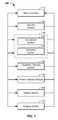
- FIG. 1illustrates component connections of a particle beam therapy system
- FIG. 2illustrates a charged particle therapy system
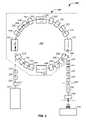
- FIG. 3illustrates straight and turning sections of a synchrotron
- FIG. 4illustrates turning magnets of a synchrotron
- FIG. 5provides a perspective view of a turning magnet
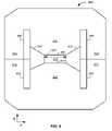
- FIG. 6illustrates a cross-sectional view of a turning magnet
- FIG. 7illustrates a cross-sectional view of a turning magnet
- FIG. 8illustrates magnetic field concentration in a turning magnet
- FIG. 9illustrates correction coils in a turning magnet
- FIG. 10illustrates a magnetic turning section of a synchrotron
- FIG. 11illustrates a magnetic field control system
- FIG. 12illustrates a charged particle extraction and intensity control system
- FIG. 14illustrates 4- or 5-dimensional scanning of a charged particle beam spot
- FIG. 15illustrates an X-ray source proximate a particle beam path
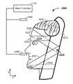
- FIG. 16illustrates a semi-vertical patient positioning system
- FIG. 17illustrates a seated positioning system
- FIG. 18illustrates a laying positioning system
- FIG. 19illustrates a head restraint system
- FIG. 20illustrates a head restraint system
- FIG. 21illustrates hand and head supports
- FIG. 22illustrates a back support
- FIG. 23illustrates a knee support
- the inventioncomprises a patient respiration monitoring and/or control method and apparatus used in conjunction with charged particle beam radiation therapy of cancerous tumors.
- Accurate and precise delivery of protons to a tumor in body tissueis critical in charged particle beam therapy. Complicating accurate and precise deliver is natural movement of the body.
- One form or movement of the bodyis related to respiration of the patient, which results in movements throughout the body and especially in the chest cavity of the patient. The movement results in relative movement of internal body parts, such as organs, as a function of time.
- a method of determining position of elements of the body at and/or in close proximity in time to the charged particle therapyis needed.
- patient respiration monitoring and/or control methods and apparatus used in conjunction with charged particle therapyare described. Particularly, a patient respiration or breath monitoring and/or control method and apparatus used in conjunction with multi-axis charged particle or proton beam radiation therapy of cancerous tumors is described.
- the respiration monitoring systemuses thermal and/or force sensors to determine where a patient is in a breathing or respiration cycle in combination with a feedback signal control delivered to the patient to inform the patient when breath control is required.
- the resulting respiration controlis timed with charged particle delivery to the tumor to enhance accuracy, precision, and efficiency of tumor treatment.
- the systemreduces the overall size of the synchrotron, provides a tightly controlled proton beam, directly reduces the size of required magnetic fields, directly reduces required operating power, and allows continual acceleration of protons in a synchrotron even during a process of extracting protons from the synchrotron.
- a cyclotronuses a constant magnetic field and a constant-frequency applied electric field. One of the two fields is varied in a synchrocyclotron. Both of these fields are varied in a synchrotron.
- a synchrotronis a particular type of cyclic particle accelerator in which a magnetic field is used to turn the particles so they circulate and an electric field is used to accelerate the particles. The synchroton carefully synchronizes the applied fields with the travelling particle beam.
- the charged particles pathcan be held constant as they are accelerated.
- Thisallows the vacuum container for the particles to be a large thin torus.
- itis easier to use some straight sections between the bending magnets and some turning sections giving the torus the shape of a round-cornered polygon.
- a path of large effective radiusis thus constructed using simple straight and curved pipe segments, unlike the disc-shaped chamber of the cyclotron type devices.
- the shapealso allows and requires the use of multiple magnets to bend the particle beam.
- the maximum energy that a cyclic accelerator can impartis typically limited by the strength of the magnetic fields and the minimum radius/maximum curvature, of the particle path.
- the maximum radiusis quite limited as the particles start at the center and spiral outward, thus this entire path must be a self-supporting disc-shaped evacuated chamber. Since the radius is limited, the power of the machine becomes limited by the strength of the magnetic field. In the case of an ordinary electromagnet, the field strength is limited by the saturation of the core because when all magnetic domains are aligned the field may not be further increased to any practical extent. The arrangement of the single pair of magnets also limits the economic size of the device.
- Synchrotronsovercome these limitations, using a narrow beam pipe surrounded by much smaller and more tightly focusing magnets.
- the ability of this device to accelerate particlesis limited by the fact that the particles must be charged to be accelerated at all, but charged particles under acceleration emit photons, thereby losing energy.
- the limiting beam energyis reached when the energy lost to the lateral acceleration required to maintain the beam path in a circle equals the energy added each cycle.
- More powerful acceleratorsare built by using large radius paths and by using more numerous and more powerful microwave cavities to accelerate the particle beam between corners. Lighter particles, such as electrons, lose a larger fraction of their energy when turning. Practically speaking, the energy of electron/positron accelerators is limited by this radiation loss, while it does not play a significant role in the dynamics of proton or ion accelerators. The energy of those is limited strictly by the strength of magnets and by the cost.
- a charged particle beam therapy systemsuch as a proton beam, hydrogen ion beam, or carbon ion beam
- the charged particle beam therapy systemis described using a proton beam.
- the aspects taught and described in terms of a proton beamare not intended to be limiting to that of a proton beam and are illustrative of a charged particle beam system. Any charged particle beam system is equally applicable to the techniques described herein.
- the charged particle beampreferably comprises a number of subsystems including any of: a main controller 110 ; an injection system 120 ; a synchrotron 130 that typically includes: (1) an accelerator system 132 and (2) an extraction system 134 ; a targeting/delivery system 140 ; a patient interface module 150 ; a display system 160 ; and/or an imaging system 170 .
- the main controller 110controls one or more of the subsystems to accurately and precisely deliver protons to a tumor of a patient. For example, the main controller 110 obtains an image, such as a portion of a body and/or of a tumor, from the imaging system 170 . The main controller 110 also obtains position and/or timing information from the patient interface module 150 . The main controller 110 then optionally controls the injection system 120 to inject a proton into a synchrotron 130 .
- the synchrotrontypically contains at least an accelerator system 132 and an extraction system 134 .
- the main controllerpreferably controls the proton beam within the accelerator system, such as by controlling speed, trajectory, and timing of the proton beam.
- the main controllerthen controls extraction of a proton beam from the accelerator through the extraction system 134 .
- the controllercontrols timing, energy, and/or intensity of the extracted beam.
- the controller 110also preferably controls targeting of the proton beam through the targeting/delivery system 140 to the patient interface module 150 .
- One or more components of the patient interface module 150are preferably controlled by the main controller 110 .
- display elements of the display system 160are preferably controlled via the main controller 110 . Displays, such as display screens, are typically provided to one or more operators and/or to one or more patients.
- the main controller 110times the delivery of the proton beam from all systems, such that protons are delivered in an optimal therapeutic manner to the patient.
- the main controller 110refers to a single system controlling the charged particle beam system 100 , to a single controller controlling a plurality of subsystems controlling the charged particle beam system 100 , or to a plurality of individual controllers controlling one or more sub-systems of the charged particle beam system 100 .
- synchrotronis used to refer to a system maintaining the charged particle beam in a circulating path; however, cyclotrons are alternatively used, albeit with their inherent limitations of energy, intensity, and extraction control.
- the charged particle beamis referred to herein as circulating along a circulating path about a central point of the synchrotron.
- the circulating pathis alternatively referred to as an orbiting path; however, the orbiting path does not refer a perfect circle or ellipse, rather it refers to cycling of the protons around a central point or region.
- the injection system 120 or ion source or charged particle beam sourcegenerates protons.
- the protonsare delivered into a vacuum tube that runs into, through, and out of the synchrotron.
- the generated protonsare delivered along an initial path 262 .
- Focusing magnets 230such as quadrupole magnets or injection quadrupole magnets, are used to focus the proton beam path.
- a quadrupole magnetis a focusing magnet.
- An injector bending magnet 232bends the proton beam toward the plane of the synchrotron 130 .
- the focused protons having an initial energyare introduced into an injector magnet 240 , which is preferably an injection Lamberson magnet.
- the initial beam path 262is along an axis off of, such as above, a circulating plane of the synchrotron 130 .
- the injector bending magnet 232 and injector magnet 240combine to move the protons into the synchrotron 130 .
- Main bending or turning magnets, dipole magnets, or circulating magnets 250are used to turn the protons along a circulating beam path 264 .
- a dipole magnetis a bending magnet.
- the main bending magnets 250bend the initial beam path 262 into a circulating beam path 264 .
- the main bending magnets 250 or circulating magnetsare represented as four sets of four magnets to maintain the circulating beam path 264 into a stable circulating beam path.
- any number of magnets or sets of magnetsare optionally used to move the protons around a single orbit in the circulation process.
- the protonspass through an accelerator 270 .
- the acceleratoraccelerates the protons in the circulating beam path 264 .
- the fields applied by the magnets 250are increased.
- the speed of the protons achieved by the accelerator 270are synchronized with magnetic fields of the main bending magnets 250 or circulating magnets to maintain stable circulation of the protons about a central point or region 280 of the synchrotron.
- the accelerator 270 /main bending magnet 250 combinationis used to accelerate and/or decelerate the circulating protons while maintaining the protons in the circulating path or orbit.
- An extraction element of the inflector/deflector system 290is used in combination with a Lamberson extraction magnet 292 to remove protons from their circulating beam path 264 within the synchrotron 130 .
- a deflector componentis a Lamberson magnet.
- the deflectormoves the protons from the circulating plane to an axis off of the circulating plane, such as above the circulating plane.
- Extracted protonsare preferably directed and/or focused using an extraction bending magnet 237 and extraction focusing magnets 235 , such as quadrupole magnets along a transport path 268 into the scanning/targeting/delivery system 140 .
- Two components of a scanning system 140 or targeting systemtypically include a first axis control 142 , such as a vertical control, and a second axis control 144 , such as a horizontal control.
- the first axis control 142allows for about 100 mm of vertical or y-axis scanning of the proton beam 268 and the second axis control 144 allows for about 700 mm of horizontal or x-axis scanning of the proton beam 268 .
- a nozzle systemis optionally used for imaging the proton beam and/or as a vacuum barrier between the low pressure beam path of the synchrotron and the atmosphere.
- Protonsare delivered with control to the patient interface module 150 and to a tumor of a patient. All of the above listed elements are optional and may be used in various permutations and combinations. Use of the above listed elements is further described, infra. Protons are delivered with control to the patient interface module 170 and to a tumor of a patient.
- the charged particle irradiationincludes a synchrotron having: a center, straight sections, and turning sections.
- the charged particle beam pathruns about the center, through the straight sections, and through the turning sections, where each of the turning sections comprises a plurality of bending magnets.
- the circulation beam pathcomprises a length of less than sixty meters, and the number of straight sections equals the number of turning sections.
- no quadrupolesare used in or around the circulating path of the synchrotron.
- a synchrotron 130preferably comprises a combination of straight sections 310 and ion beam turning sections 320 .
- the circulating path of the protonsis not circular in a synchrotron, but is rather a polygon with rounded corners.
- the synchrotron 130which is also referred to as an accelerator system, has four straight elements and four turning sections.
- straight sections 310include the: inflector 240 , accelerator 270 , extraction system 290 , and deflector 292 .
- ion beam turning sections 320which are also referred to as magnet sections or turning sections. Turning sections are further described, infra.
- the synchrotron 130comprises four straight sections 310 and four turning sections 320 where each of the four turning sections use one or more magnets to turn the proton beam about ninety degrees.
- the ability to closely space the turning sections and efficiently turn the proton beamresults in shorter straight sections. Shorter straight sections allows for a synchrotron design without the use of focusing quadrupoles in the circulating beam path of the synchrotron.
- the illustrated synchrotronhas about a five meter diameter versus eight meter and larger cross-sectional diameters for systems using a quadrupole focusing magnet in the circulating proton beam path.
- Each of the turning sectionspreferably comprises multiple magnets, such as about 2, 4, 6, 8, 10, or 12 magnets.
- four turning magnets 410 , 420 , 430 , 440 in the first turning section 320are used to illustrate key principles, which are the same regardless of the number of magnets in a turning section 320 .
- a turning magnet 410is a particular type of circulating magnet 250 .
- the Lorentz forceis the force on a point charge due to electromagnetic fields.
- Equation 1F is the force in newtons; B is the magnetic field in Teslas; and v is the instantaneous velocity of the particles in meters per second.
- the turning sectionincludes a gap 510 .
- the gapis preferably a flat gap, allowing for a magnetic field across the gap that is more uniform, even, and intense.
- a magnetic fieldenters the gap through a magnetic field incident surface and exits the gap through a magnetic field exiting surface.
- the gap 510runs in a vacuum tube between two magnet halves.
- the gapis controlled by at least two parameters: (1) the gap 510 is kept as large as possible to minimize loss of protons and (2) the gap 510 is kept as small as possible to minimize magnet sizes and the associated size and power requirements of the magnet power supplies.
- the flat nature of the gap 510allows for a compressed and more uniform magnetic field across the gap.
- One example of a gap dimensionis to accommodate a vertical proton beam size of about two centimeters with a horizontal beam size of about five to six centimeters.
- a larger gap sizerequires a larger power supply. For instance, if the gap size doubles in vertical size, then the power supply requirements increase by about a factor of four.
- the flatness of the gapis also important. For example, the flat nature of the gap allows for an increase in energy of the extracted protons from about 250 to about 330 MeV. More particularly, if the gap 510 has an extremely flat surface, then the limits of a magnetic field of an iron magnet are reachable.
- An exemplary precision of the flat surface of the gap 510is a polish of less than about five microns and preferably with a polish of about one to three micrometers. Unevenness in the surface results in imperfections in the applied magnetic field. The polished flat surface spreads unevenness of the applied magnetic field.
- the charged particle beammoves through the gap with an instantaneous velocity, v.
- a first magnetic coil 520 and a second magnetic coil 530run above and below the gap 510 , respectively.
- Current running through the coils 520 , 530results in a magnetic field, B, running through the single magnet turning section 410 .
- the magnetic field, Bruns upward, which results in a force, F, pushing the charged particle beam inward toward a central point of the synchrotron, which turns the charged particle beam in an arc.
- the coils 520 , 530typically have return elements 540 , 550 or turns at the end of one magnet, such as at the end of the first magnet turning section 410 .
- the return elements 540 , 550take space. The space reduces the percentage of the path about one orbit of the synchrotron that is covered by the turning magnets. This leads to portions of the circulating path where the protons are not turned and/or focused and allows for portions of the circulating path where the proton path defocuses. Thus, the space results in a larger synchrotron. Therefore, the space between magnet turning sections 560 is preferably minimized.
- the second turning magnetis used to illustrate that the coils 520 , 530 optionally run along a plurality of magnets, such as 2, 3, 4, 5, 6, or more magnets. Coils 520 , 530 running across turning section magnets allows for two turning section magnets to be spatially positioned closer to each other due to the removal of the steric constraint of the turns, which reduces and/or minimizes the space 560 between two turning section magnets.
- the magnet assemblyhas a first magnet 610 and a second magnet 620 .
- a magnetic field induced by coils, described infraruns between the first magnet 610 to the second magnet 620 across the gap 510 .
- Return magnetic fieldsrun through a first yoke 612 and second yoke 622 .
- the charged particlesrun through the vacuum tube in the gap.
- protonsrun into FIG. 6 through the gap 510 and the magnetic field, illustrated as vector B, applies a force F to the protons pushing the protons towards the center of the synchrotron, which is off page to the right in FIG. 6 .
- the magnetic fieldis created using windings.
- a first coilmakes up a first winding coil 650 and a second coil of wire makes up a second winding coil 660 .
- Isolating gaps 630 , 640such as air gaps, isolate the iron based yokes 612 , 622 from the gap 510 .
- the gapis approximately flat to yield a uniform magnetic field across the gap, as described supra.
- the ends of a single turning magnetare preferably beveled.
- Nearly perpendicular or right angle edges of a turning magnet 410are represented by a dashed lines 674 , 684 .
- the edge of the turning magnetis beveled at angles alpha, ⁇ , and beta, ⁇ , which is the off perpendicular angle between the right angles 674 , 684 and beveled edges 672 , 682 .
- the angle alphais used to describe the effect and the description of angle alpha applies to angle beta, but angle alpha is optionally different from angle beta.
- the angle alphaprovides an edge focusing effect. Beveling the edge of the turning magnet 410 at angle alpha focuses the proton beam.
- Multiple turning magnetsprovide multiple magnet edges that each have edge focusing effects in the synchrotron 310 . If only one turning magnet is used, then the beam is only focused once for angle alpha or twice for angle alpha and angle beta. However, by using smaller turning magnets, more turning magnets fit into the turning sections 320 of the synchrotron 310 . For example, if four magnets are used in a turning section 320 of the synchrotron, then there are eight possible edge focusing effect surfaces, two edges per magnet. The eight focusing surfaces yield a smaller cross-sectional beam size. This allows the use of a smaller gap 510 .
- edge focusing effects in the turning magnetsresults in not only a smaller gap, but also the use of smaller magnets and smaller power supplies.
- a synchrotron 310 having four turning sections 320 where each turning sections has four turning magnets and each turning magnet has two focusing edgesa total of thirty-two focusing edges exist for each orbit of the protons in the circulating path of the synchrotron 310 .
- 2, 6, or 8 magnetsare used in a given turning section, or if 2, 3, 5, or 6 turning sections are used, then the number of edge focusing surfaces expands or contracts according to equation 2.
- TFENTS ⁇ M NTS ⁇ FE M eq . ⁇ 2
- TFEis the number of total focusing edges
- NTSis the number of turning section
- Mis the number of magnets
- FEis the number of focusing edges.
- the inventorshave determined that multiple smaller magnets have benefits over fewer larger magnets. For example, the use of 16 small magnets yields 32 focusing edges whereas the use of 4 larger magnets yields only 8 focusing edges.
- the use of a synchrotron having more focusing edgesresults in a circulating path of the synchrotron built without the use of focusing quadrupoles magnets. All prior art synchrotrons use quadrupoles in the circulating path of the synchrotron. Further, the use of quadrupoles in the circulating path necessitates additional straight sections in the circulating path of the synchrotron. Thus, the use of quadrupoles in the circulating path of a synchrotron results in synchrotrons having larger diameters or larger circumferences.
- the synchrotronhas:
- FIG. 6the incident magnetic field surface 670 of the first magnet 610 is further described.
- FIG. 6is not to scale and is illustrative in nature. Local imperfections or unevenness in quality of the finish of the incident surface 670 results in inhomogeneities or imperfections in the magnetic field applied to the gap 510 .
- the incident surface 670is flat, such as to within about a zero to three micron finish polish, or less preferably to about a ten micron finish polish.
- the first magnet 610preferably contains an initial cross-sectional distance 810 of the iron based core.
- the contours of the magnetic fieldare shaped by the magnets 610 , 620 and the yokes 612 , 622 .
- the iron based coretapers to a second cross-sectional distance 820 .
- the magnetic field in the magnetpreferentially stays in the iron based core as opposed to the gaps 630 , 640 .
- the magnetic fieldconcentrates.
- the change in shape of the magnet from the longer distance 810 to the smaller distance 820acts as an amplifier.
- the concentration of the magnetic fieldis illustrated by representing an initial density of magnetic field vectors 830 in the initial cross-section 810 to a concentrated density of magnetic field vectors 840 in the final cross-section 820 .
- the concentration of the magnetic field due to the geometry of the turning magnetsresults in fewer winding coils 650 , 660 being required and also a smaller power supply to the coils being required.
- the initial cross-section distance 810is about fifteen centimeters and the final cross-section distance 820 is about ten centimeters.
- the concentration of the magnetic fieldis about 15/10 or 1.5 times at the incident surface 670 of the gap 510 , though the relationship is not linear.
- the taper 860has a slope, such as about 20 to 60 degrees.
- the concentration of the magnetic fieldsuch as by 1.5 times, leads to a corresponding decrease in power consumption requirements to the magnets.
- the first magnet 610preferably contains an initial cross-sectional distance 810 of the iron based core.
- the contours of the magnetic fieldare shaped by the magnets 610 , 620 and the yokes 612 , 622 .
- the coretapers to a second cross-sectional distance 820 with a smaller angle theta, ⁇ .
- the magnetic field in the magnetpreferentially stays in the iron based core as opposed to the gaps 630 , 640 .
- the magnetic fieldconcentrates.
- the smaller angle, thetaresults in a greater amplification of the magnetic field in going from the longer distance 810 to the smaller distance 820 .
- the concentration of the magnetic fieldis illustrated by representing an initial density of magnetic field vectors 830 in the initial cross-section 810 to a concentrated density of magnetic field vectors 840 in the final cross-section 820 .
- the concentration of the magnetic field due to the geometry of the turning magnetsresults in fewer winding coils 650 , 660 being required and also a smaller power supply to the winding coils 650 , 660 being required.
- optional correction coils 910 , 920are illustrated that are used to correct the strength of one or more turning magnets.
- the correction coils 920 , 930supplement the winding coils 650 , 660 .
- the correction coils 910 , 920have correction coil power supplies that are separate from winding coil power supplies used with the winding coils 650 , 660 .
- the correction coil power suppliestypically operate at a fraction of the power required compared to the winding coil power supplies, such as about 1, 2, 3, 5, 7, or 10 percent of the power and more preferably about 1 or 2 percent of the power used with the winding coils 650 , 660 .
- the smaller operating power applied to the correction coils 920 , 920allows for more accurate and/or precise control of the correction coils.
- the correction coilsare used to adjust for imperfection in the turning magnets 410 , 420 , 430 , 440 .
- FIG. 10an example of winding coils and correction coils about a plurality of turning magnets 410 , 420 , 430 , 440 in an ion beam turning section 320 is illustrated.
- One or more high precision magnetic field sensorsare placed into the synchrotron and are used to measure the magnetic field at or near the proton beam path.
- the magnetic sensorsare optionally placed between turning magnets and/or within a turning magnet, such as at or near the gap or at or near the magnet core or yoke.
- the sensorsare part of a feedback system to the correction coils.
- the systempreferably stabilizes the magnetic field in the synchrotron elements rather that stabilizing the current applied to the magnets. Stabilization of the magnetic field allows the synchrotron to come to a new energy level quickly. This allows the system to be controlled to an operator or algorithm selected energy level with each pulse of the synchrotron and/or with each breath of the patient.
- a respiratory sensor 1110senses the breathing cycle of the subject.
- the respiratory sensorsends the information to an algorithm in a magnetic field controller 1120 , typically via the patient interface module 150 and/or via the main controller 110 or a subcomponent thereof.
- the algorithmpredicts and/or measures when the subject is at a particular point in the respiration cycle, such as at the top or bottom of a breath.
- Magnetic field sensors 1130such as the high precision magnetic field sensors 1050 , are used as input to the magnetic field controller, which controls a magnet power supply 1140 for a given magnetic field 1150 , such as within a first turning magnet 410 of a synchrotron 130 .
- the control feedback loopis thus used to dial the synchrotron to a selected energy level and deliver protons with the desired energy at a selected point in time, such as at the bottom of the breath. More particularly, the synchrotron accelerates the protons and the control feedback loop keeps the protons in the circulating path by synchronously adjusting the magnetic field strength of the turning magnets. Intensity of the proton beam is also selectable at this stage.
- the feedback control to the correction coilsallows rapid selection of energy levels of the synchrotron that are tied to the patient's respiration cycle. This system is in stark contrast to a system where the current is stabilized and the synchrotron deliver pulses with a period, such as 10 or 20 cycles second with a fixed period.
- the feedback or the magnetic field design coupled with the correction coilsallows for the extraction cycle to match the varying respiratory rate of the patient.
- FIG. 10an example of a winding coil 1030 that covers four turning magnets 410 , 420 , 430 , 440 is provided. As described, supra, this system reduces space between turning section allowing more magnetic field to be applied per radian of turn.
- a first correction coil 1010is illustrated that is used to correct the magnetic field for the first turning magnet 410 . Individual correction coils for each turning magnet are preferred and individual correction coils yield the most precise and/or accurate magnetic field in each turning section magnet. Particularly, the individual correction coil 1010 is used to compensate for imperfections in the individual magnet of a given turning section.
- corresponding magnetic fieldsare individually adjustable in a series of feedback loops, via a magnetic field monitoring system 1030 , as an independent coil is used for each turning section.
- a multiple magnet correction coil 1020is used to correct the magnetic field for a plurality of turning section magnets.
- gap surfaceis described in terms of the first turning magnet 410 , the discussion applies to each of the turning magnets in the synchrotron.
- gap 510 surfaceis described in terms of the magnetic field incident surface 670 , the discussion additionally optionally applies to the magnetic field exiting surface 680 .
- the magnetic field incident surface 670 of the first magnet 610is preferably about flat, such as to within about a zero to three micron finish polish or less preferably to about a ten micron finish polish.
- the polished surfacespreads the unevenness of the applied magnetic field across the gap 510 .
- the very flat surfacesuch as about 0, 1, 2, 4, 6, 8, 10, 15, or 20 micron finish, allows for a smaller gap size, a smaller applied magnetic field, smaller power supplies, and tighter control of the proton beam cross-sectional area.
- FIG. 12an exemplary proton extraction process from the synchrotron 130 is illustrated.
- FIG. 12removes elements represented in FIG. 2 , such as the turning magnets, which allows for greater clarity of presentation of the proton beam path as a function of time.
- protonsare extracted from the synchrotron 130 by slowing the protons.
- the protonswere initially accelerated in a circulating path 264 , which is maintained with a plurality of turning magnets 250 .
- the circulating pathis referred to herein as an original central beamline 264 .
- the protonsrepeatedly cycle around a central point in the synchrotron 280 .
- the proton pathtraverses through an RF cavity system 1210 .
- an RF fieldis applied across a first blade 1212 and a second blade 1214 , in the RF cavity system 1210 .
- the first blade 1212 and second blade 1214are referred to herein as a first pair of blades.
- a radio-frequency (RF) voltageis applied across the first pair of blades, where the first blade 1212 of the first pair of blades is on one side of the circulating proton beam path 264 and the second blade 1214 of the first pair of blades is on an opposite side of the circulating proton beam path 264 .
- the applied RF fieldapplies energy to the circulating charged-particle beam.
- the applied RF fieldalters the orbiting or circulating beam path slightly of the protons from the original central beamline 264 to an altered circulating beam path 265 .
- the RF fieldfurther moves the protons off of the original proton beamline 264 .
- the altered beamlineis slightly elliptical.
- the applied RF fieldis timed to apply outward or inward movement to a given band of protons circulating in the synchrotron accelerator.
- Each orbit of the protonsis slightly more off axis compared to the original circulating beam path 264 .
- Successive passes of the protons through the RF cavity systemare forced further and further from the original central beamline 264 by altering the direction and/or intensity of the RF field with each successive pass of the proton beam through the RF field.
- the RF voltageis frequency modulated at a frequency about equal to the period of one proton cycling around the synchrotron for one revolution or at a frequency than is an integral multiplier of the period of one proton cycling about the synchrotron.
- the applied RF frequency modulated voltageexcites a betatron oscillation.
- the oscillationis a sine wave motion of the protons.
- the process of timing the RF field to a given proton beam within the RF cavity systemis repeated thousands of times with each successive pass of the protons being moved approximately one micrometer further off of the original central beamline 264 . For clarity, the effect of the approximately 1000 changing beam paths with each successive path of a given band of protons through the RF field are illustrated as the altered beam path 265 .
- the altered circulating beam path 265touches a material 1230 , such as a foil or a sheet of foil.
- the foilis preferably a lightweight material, such as beryllium, a lithium hydride, a carbon sheet, or a material of low nuclear charge.
- a material of low nuclear chargeis a material composed of atoms consisting essentially of atoms having six or fewer protons.
- the foilis preferably about 10 to 150 microns thick, is more preferably 30 to 100 microns thick, and is still more preferably 40-60 microns thick. In one example, the foil is beryllium with a thickness of about 50 microns.
- the reduced radius of curvature 266 pathis also referred to herein as a path having a smaller diameter of trajectory or a path having protons with reduced energy.
- the reduced radius of curvature 266is typically about two millimeters less than a radius of curvature of the last pass of the protons along the altered proton beam path 265 .
- the thickness of the material 1230is optionally adjusted to created a change in the radius of curvature, such as about 1 ⁇ 2, 1, 2, 3, or 4 mm less than the last pass of the protons 265 or original radius of curvature 264 .
- Protons moving with the smaller radius of curvaturetravel between a second pair of blades.
- the second pair of bladesis physically distinct and/or are separated from the first pair of blades.
- one of the first pair of bladesis also a member of the second pair of blades.
- the second pair of bladesis the second blade 1214 and a third blade 1216 in the RF cavity system 1210 .
- a high voltage DC signalsuch as about 1 to 5 kV, is then applied across the second pair of blades, which directs the protons out of the synchrotron through a deflector 292 , such as a Lamberson magnet, into a transport path 268 .
- Control of acceleration of the charged particle beam path in the synchrotron with the accelerator and/or applied fields of the turning magnets in combination with the above described extraction systemallows for control of the intensity of the extracted proton beam, where intensity is a proton flux per unit time or the number of protons extracted as a function of time. For example, when a current is measured beyond a threshold, the RF field modulation in the RF cavity system is terminated or reinitiated to establish a subsequent cycle of proton beam extraction. This process is repeated to yield many cycles of proton beam extraction from the synchrotron accelerator.
- the extraction systemdoes not depend on any change any change in magnetic field properties, it allows the synchrotron to continue to operate in acceleration or deceleration mode during the extraction process. Stated differently, the extraction process does not interfere with synchrotron.
- traditional extraction systemsintroduce a new magnetic field, such as via a hexapole, during the extraction process. More particularly, traditional synchrotrons have a magnet, such as a hexapole magnet, that is off during an acceleration stage. During the extraction phase, the hexapole magnetic field is introduced to the circulating path of the synchrotron. The introduction of the magnetic field necessitates two distinct modes, an acceleration mode and an extraction mode, which are mutually exclusive in time.
- Control of applied fieldsuch as a radio-frequency (RF) field, frequency and magnitude in the RF cavity system 1210 allows for intensity control of the extracted proton beam, where intensity is extracted proton flux per unit time or the number of protons extracted as a function of time.
- RFradio-frequency
- the resulting currentis converted to a voltage and is used as part of a ion beam intensity monitoring system or as part of an ion beam feedback loop for controlling beam intensity.
- the voltageis optionally measured and sent to the main controller 110 or to a controller subsystem, such as an intensity controller 1240 .
- some of the protonslose a small fraction of their energy, such as about one-tenth of a percent, which results in a secondary electron. That is, protons in the charged particle beam push some electrons when passing through material 1230 giving the electrons enough energy to cause secondary emission.
- the resulting electron flowresults in a current or signal that is proportional to the number of protons going through the target material 1230 .
- the resulting currentis preferably converted to voltage and amplified.
- the resulting signalis referred to as a measured intensity signal.
- the amplified signal or measured intensity signal resulting from the protons passing through the material 1230is preferably used in controlling the intensity of the extracted protons.
- the measured intensity signalis compared to a goal signal, which is predetermined in an irradiation of the tumor plan.
- the difference between the measured intensity signal and the planned for goal signalis calculated.
- the differenceis used as a control to the RF generator.
- the measured flow of current resulting from the protons passing through the material 1230is used as a control in the RF generator to increase or decrease the number of protons undergoing betatron oscillation and striking the material 1230 .
- the voltage determined off of the material 1230is used as a measure of the orbital path and is used as a feedback control to control the RF cavity system.
- the measured intensity signalis not used in the feedback control and is just used as a monitor of the intensity of the extracted protons.
- the photons striking the material 1230is a step in the extraction of the protons from the synchrotron 130 .
- the measured intensity signalis used to change the number of protons per unit time being extracted, which is referred to as intensity of the proton beam.
- the intensity of the proton beamis thus under algorithm control. Further, the intensity of the proton beam is controlled separately from the velocity of the protons in the synchrotron 130 . Hence, intensity of the protons extracted and the energy of the protons extracted are independently variable.
- protonsinitially move at an equilibrium trajectory in the synchrotron 130 .
- An RF fieldis used to excite the protons into a betatron oscillation.
- the frequency of the protons orbitis about 10 MHz.
- the first protonshit an outer edge of the target material 130 .
- the specific frequencyis dependent upon the period of the orbit.
- the protonspush electrons through the foil to produce a current.
- the currentis converted to voltage and amplified to yield a measured intensity signal.
- the measured intensity signalis used as a feedback input to control the applied RF magnitude, RF frequency, or RF field.
- the measured intensity signalis compared to a target signal and a measure of the difference between the measured intensity signal and target signal is used to adjust the applied RF field in the RF cavity system 1210 in the extraction system to control the intensity of the protons in the extraction step.
- the signal resulting from the protons striking and/or passing through the material 130is used as an input in RF field modulation.
- An increase in the magnitude of the RF modulationresults in protons hitting the foil or material 130 sooner.
- By increasing the RFmore protons are pushed into the foil, which results in an increased intensity, or more protons per unit time, of protons extracted from the synchrotron 130 .
- a detector external to the synchrotron 130is used to determine the flux of protons extracted from the synchrotron and a signal from the external detector is used to alter the RF field or RF modulation in the RF cavity system 1210 .
- the external detectorgenerates an external signal, which is used in a manner similar to the measured intensity signal, described in the preceding paragraphs.
- the RF field modulation in the RF cavity systemis terminated or reinitiated to establish a subsequent cycle of proton beam extraction. This process is repeated to yield many cycles of proton beam extraction from the synchrotron accelerator.
- intensity modulation of the extracted proton beamis controlled by the main controller 110 .
- the main controller 110optionally and/or additionally controls timing of extraction of the charged particle beam and energy of the extracted proton beam.
- a method or apparatus for extracting intensity controlled charged particles from charged particles circulating in a synchrotron of a charged particle cancer therapy systemincludes: oscillation blades with a radio-frequency voltage across the for inducing oscillating charged particles from the charged particles circulating in the synchrotron; an extraction material where the oscillating charged particles traverse the extraction material during use generating both reduced energy charged particles and secondary emission electrons or a current; and extraction blades used in extracting the energy controlled and intensity controlled charged particles from the synchrotron.
- the systemincludes a feedback intensity controller that generates a measure of the secondary emission electrons, compares the measure and a target signal, such as an irradiation plan signal 1260 for each beam position striking the tumor 1520 , and having the intensity controller adjusts amplitude of the radio-frequency voltage based on the comparison yielding intensity controlled and energy controlled extracted charged particles.
- the beam intensityis optionally measured with a detector 1250 after extraction from the synchrotron.
- the benefits of the systeminclude a multi-dimensional scanning system.
- the systemallows independence in: (1) energy of the protons extracted and (2) intensity of the protons extracted. That is, energy of the protons extracted is controlled by an energy control system and an intensity control system controls the intensity of the extracted protons.
- the energy control system and intensity control systemare optionally independently controlled.
- the main controller 110controls the energy control system and the main controller simultaneously controls the intensity control system to yield an extracted proton beam with controlled energy and controlled intensity where the controlled energy and controlled intensity are independently variable.
- the irradiation spot hitting the tumoris under independent control of:
- the patientis optionally independently rotated relative to a translational axis of the proton beam at the same time.
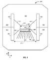
- FIG. 13a beam delivery and tissue volume scanning system is illustrated.
- the worldwide radiotherapy communityuses a method of dose field forming using a pencil beam scanning system.
- FIG. 13illustrates a spot scanning system or tissue volume scanning system.
- the proton beamis controlled, in terms of transportation and distribution, using an inexpensive and precise scanning system.
- the scanning systemis an active system, where the beam is focused into a spot focal point of about one-half, one, two, or three millimeters in diameter.
- the focal pointis translated along two axes while simultaneously altering the applied energy of the proton beam, which effectively changes the third dimension of the focal point.
- FIG. 13illustrates a spot scanning system or tissue volume scanning system.
- the proton beamis controlled, in terms of transportation and distribution, using an inexpensive and precise scanning system.
- the scanning systemis an active system, where the beam is focused into a spot focal point of about one-half, one, two, or three millimeters in diameter.
- the focal pointis translated along two axes while simultaneously alter
- the spotis translated up a vertical axis, is moved horizontally, and is then translated down a vertical axis.
- currentis used to control a vertical scanning system having at least one magnet.
- the applied currentalters the magnetic field of the vertical scanning system to control the vertical deflection of the proton beam.
- a horizontal scanning magnet systemcontrols the horizontal deflection of the proton beam.
- the degree of transport along each axesis controlled to conform to the tumor cross-section at the given depth.
- the depthis controlled by changing the energy of the proton beam. For example, the proton beam energy is decreased, so as to define a new penetration depth, and the scanning process is repeated along the horizontal and vertical axes covering a new cross-sectional area of the tumor.
- the three axes of controlallow scanning or movement of the proton beam focal point over the entire volume of the cancerous tumor.
- the time at each spot and the direction into the body for each spotis controlled to yield the desired radiation does at each sub-volume of the cancerous volume while distributing energy hitting outside of the tumor.
- the focused beam spot volume dimensionis preferably tightly controlled to a diameter of about 0.5, 1, or 2 millimeters, but is alternatively several centimeters in diameter.
- Preferred design controlsallow scanning in two directions with: (1) a vertical amplitude of about 100 mm amplitude and frequency up to 200 Hz; and (2) a horizontal amplitude of about 700 mm amplitude and frequency up to 1 Hz. More or less amplitude in each axis is possible by altering the scanning magnet systems.
- the proton beamgoes along a z-axis controlled by the beam energy, the horizontal movement is along an x-axis, and the vertical direction is along a y-axis.
- the distance the protons move along the z-axis into the tissue, in this example,is controlled by the kinetic energy of the proton.
- This coordinate systemis arbitrary and exemplary.
- the actual control of the proton beamis controlled in 3-dimensional space using two scanning magnet systems and by controlling the kinetic energy of the proton beam.
- the use of the extraction system, described supra,allows for different scanning patterns. Particularly, the system allows simultaneous adjustment of the x-, y-, and z-axes in the irradiation of the solid tumor.
- the systemallows for moving along the z-axes while simultaneously adjusting the x- and or y-axes.
- the tumoris optionally irradiated in three simultaneous dimensions. For example, the tumor is irradiated around an outer edge of the tumor in three dimensions. Then the tumor is irradiated around an outer edge of an internal section of the tumor. This process is repeated until the entire tumor is irradiated.
- the outer edge irradiationis preferably coupled with simultaneous rotation of the subject, such as about a vertical y-axis. This system allows for maximum efficiency of deposition of protons to the tumor, as defined using the Bragg peak, to the tumor itself with minimal delivery of proton energy to surrounding healthy tissue.
- the systemallows for multi-axes control of the charged particle beam system in a small space with low power supply.
- the systemuses multiple magnets where each magnet has at least one edge focusing effect in each turning section of the synchrotron and/or multiple magnets having concentrating magnetic field geometry, as described supra.
- the multiple edge focusing effects in the circulating beam path of the synchrotron combined with the concentration geometry of the magnets and described extraction systemyields a synchrotron having:
- the resultis a 3-dimensional scanning system, x-, y-, and z-axes control, where the z-axes control resides in the synchrotron and where the z-axes energy is variably controlled during the extraction process inside the synchrotron.
- a targeting system 140 used to direct the protons to the tumor with 4-dimensional scanning controlis provided, where the 4-dimensional scanning control is along the x-, y-, and z-axes along with intensity control, as described supra.
- charged particles traveling along the transport path 268are directed through a first axis control element 142 , such as a vertical control, and a second axis control element 144 , such as a horizontal control and into a tumor 1520 .
- the extraction systemalso allows for simultaneous variation in the z-axis.
- the intensity or dose of the extracted beamis optionally simultaneously and independently controlled and varied.
- all four dimensions defining the targeting spot of the proton delivery in the tumorare simultaneously variable.
- the simultaneous variation of the proton delivery spotis illustrated in FIG. 14 by the spot delivery path 269 .
- the protonsare initially directed around an outer edge of the tumor and are then directed around an inner radius of the tumor.
- a multi-field illumination processis used where a not yet irradiated portion of the tumor is preferably irradiated at the further distance of the tumor from the proton entry point into the body. This yields the greatest percentage of the proton delivery, as defined by the Bragg peak, into the tumor and minimizes damage to peripheral healthy tissue.
- an X-ray systemis used to illustrate an imaging system.
- An X-rayis preferably collected either (1) just before or (2) concurrently with treating a subject with proton therapy for a couple of reasons.
- movement of the bodychanges the local position of the tumor in the body relative to other body constituents. If the subject has an X-ray taken and is then bodily moved to a proton treatment room, accurate alignment of the proton beam to the tumor is problematic. Alignment of the proton beam to the tumor using one or more X-rays is best performed at the time of proton delivery or in the seconds or minutes immediately prior to proton delivery and after the patient is placed into a therapeutic body position, which is typically a fixed position or partially immobilized position.
- the X-ray taken after positioning the patientis used for verification of proton beam alignment to a targeted position, such as a tumor and/or internal organ position.
- An X-rayis preferably taken just before treating the subject to aid in patient positioning.
- an X-ray of a large body areais not needed.
- an X-ray of only a local areais collected.
- the X-rayhas an X-ray path.
- the proton beamhas a proton beam path.
- Overlaying the X-ray path with the proton beam pathis one method of aligning the proton beam to the tumor.
- this methodinvolves putting the X-ray equipment into the proton beam path, taking the X-ray, and then moving the X-ray equipment out of the beam path. This process takes time. The elapsed time while the X-ray equipment moves has a couple of detrimental effects.
- the bodymoves.
- the resulting movementdecreases precision and/or accuracy of subsequent proton beam alignment to the tumor.
- the time require to move the X-ray equipmentis time that the proton beam therapy system is not in use, which decreases the total efficiency of the proton beam therapy system.
- an X-rayis generated close to, but not in, the proton beam path.
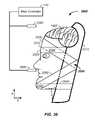
- a proton beam therapy system and an X-ray system combination 1500is illustrated in FIG. 15 .
- the proton beam therapy systemhas a proton beam 268 in a transport system after the deflector 292 of the synchrotron 130 .
- the proton beamis directed by the targeting/delivery system 140 to a tumor 1520 of a patient 1530 .
- the X-ray system 1505includes an electron beam source 1540 generating an electron beam 1550 .
- the electron beamis directed to an X-ray generation source 1560 , such as a piece of tungsten.
- the tungsten X-ray sourceis located about 1, 2, 3, 5, 10, 15, or 20 millimeters from the proton beam path 268 .
- the electron beam 1550hits the tungsten, X-rays are generated in all directions. X-rays are blocked with a port 1562 and are selected for an X-ray beam path 1570 .
- the X-ray beam path 1570 and proton beam path 260run substantially in parallel as they progress to the tumor 1520 .
- the distance between the X-ray beam path 1570 and proton beam path 269preferably diminishes to near zero and/or the X-ray beam path 1570 and proton beam path 269 overlap by the time they reach the tumor 1520 .
- Simple geometryshows this to be the case given the long distance, of at least a meter, between the tungsten and the tumor 1520 .
- the distanceis illustrated as a gap 1580 in FIG. 15 .
- the X-raysare detected at an X-ray detector 1590 , which is used to form an image of the tumor 1520 and/or position of the patient 1530 .
- Electronsare generated at a cathode 1510 , focused with a control electrode 1512 , and accelerated with a series of accelerating electrodes 1562 and focused with focusing electrodes 1565 .
- the accelerated electrons 1550impact an X-ray generation source 1560 resulting in generated X-rays that are then directed along an X-ray path 1570 to the subject 1530 .
- the concentrating of the electrons from a first diameter of the cathode to a second diameter of the accelerated electrons 1550allows the cathode to operate at a reduced temperature and still yield the necessary amplified level of electrons at the X-ray generation source 1560 .
- the X-ray generation source 1560is the anode coupled with the cathode 1510 and/or the X-ray generation source is substantially composed of tungsten.
- the systemgenerates an X-ray beam that lies in substantially the same path as the proton therapy beam.
- the X-ray beamis generated by striking a tungsten or equivalent material with an electron beam.
- the X-ray generation sourceis located proximate to the proton beam path.
- Geometry of the incident electrons, geometry of the X-ray generation material, and geometry of the X-ray beam blocker 262yield an X-ray beam that runs either in substantially in parallel with the proton beam or results in an X-ray beam path that starts proximate the proton beam path an expands to cover and transmit through a tumor cross-sectional area to strike an X-ray detector array or film allowing imaging of the tumor from a direction and alignment of the proton therapy beam.
- the X-ray imageis then used to control the charged particle beam path to accurately and precisely target the tumor, and/or is used in system verification and validation.
- Accurate and precise delivery of a proton beam to a tumor of a patientrequires: (1) positioning control of the proton beam and (2) positioning control of the patient.
- the proton beamis controlled using algorithms and magnetic fields to a diameter of about 0.5, 1, or 2 millimeters. This section addresses partial immobilization, restraint, and/or alignment of the patient to insure the tightly controlled proton beam efficiently hits a target tumor and not surrounding healthy tissue as a result of patient movement.
- an x-, y-, and z-axes coordinate system and rotation axisis used to describe the orientation of the patient relative to the proton beam.
- the z-axisrepresent travel of the proton beam, such as the depth of the proton beam into the patient.
- the x-axisrefers to moving left or right across the patient and the y-axis refers to movement up or down the patient.
- a first rotation axisis rotation of the patient about the y-axis and is referred to herein as a rotation axis, platform 1612 rotation axis, or y-axis of rotation.
- the proton beam path 269optionally runs in any direction.
- the proton beam path running through a treatment roomis described as running horizontally through the treatment room.
- a semi-vertical partial immobilization system(2) a sitting partial immobilization system; and (3) a laying position.
- Elements described for one immobilizationapply to other immobilization systems with small changes.
- a head restwill adjust along one axis for a reclined position, along a second axis for a seated position, and along a third axis for a laying position.
- the headrestitself is similar for each immobilization position.
- a semi-vertical patient positioning and/or partial immobilization system 1600is described.
- the semi-vertical patient positioning system 1600is preferably used in conjunction with proton therapy of tumors in the torso.
- the patient positioning and/or immobilization system 1600controls and/or restricts movement of the patient during proton beam therapy.
- the patientis positioned in a semi-vertical position in a proton beam therapy system. As illustrated, the patient is reclining at an angle alpha, ⁇ , about 45 degrees off of the y-axis as defined by an axis running from head to foot of the patient.
- the patientis optionally completely standing in a vertical position of zero degrees off the of y-axis or is in a semi-vertical position alpha that is reclined about 5, 10, 15, 20, 25, 30, 35, 40, 45, 50, 55, 60, or 65 degrees off of the y-axis toward the z-axis.
- patient positioning constraints 1615are used to maintain the patient in a treatment position, including one or more of: a seat support 1620 , a back support 1630 , a head support 1640 , an arm support 1650 , a knee support 1660 , and a foot support 1670 .
- the constraintsare optionally and independently rigid or semi-rigid. Examples of a semi-rigid material include a high or low density foam or a visco-elastic foam.
- the foot support 1670is preferably rigid and the back support 1630 is preferably semi-rigid, such as a high density foam material.
- One or more of the positioning constraints 1615are movable and/or under computer control for rapid positioning and/or immobilization of the patient.
- the seat support 1620is adjustable along a seat adjustment axis 1622 , which is preferably the y-axis;
- the back support 1630is adjustable along a back support axis 1632 , which is preferably dominated by z-axis movement with a y-axis element;
- the head support 1640is adjustable along a head support axis 1642 , which is preferably dominated by z-axis movement with a y-axis element;
- the arm support 1650is adjustable along an arm support axis, which is preferably dominated by z-axis movement with a y-axis element;
- the knee support 1660is adjustable along a knee support axis 1662 , which is preferably dominated by y-axis movement with a z-axis element;
- the foot support 1670is adjustable along a foot support axis, which is preferably dominated by y-axis movement with a z-axis element.
- the patientis preferably positioned on a patient positioning unit 1610 , which optionally includes a bottom unit 1612 and a top unit 1614 .
- the bottom unitis optionally a patient support platform or is attached to a patient support platform 1618 .
- some of the patient positioning constraints 1615are fixed to and supported by the patient positioning unit 1610 .
- some of the patient positioning constraints 1615are fixed to and supported by the bottom unit 1612 and some of the patient positioning constraints 1615 are fixed to and supported by the top unit 1614 .
- the patient positioning unit 1610is adjustable along the y-axis 1616 to allow vertical positioning of the patient relative to the proton therapy beam 260 .
- the patient positioning unit 1610is rotatable about a rotation axis 1617 , such as about the y-axis, to allow rotational control and positioning of the patient relative to the proton beam path 260 .
- the rotation of the positioning unitis illustrated about the rotation axis 1617 at three distinct times, t 1 , t 2 , and t 3 . Any of the positioning embodiments described herein are optionally rotatable about eh rotation or y-axis.
- an optional camera 1680is illustrated.
- the cameraviews the subject 1530 creating an video image.
- the imageis provided to one or more operators of the charged particle beam system and allows the operators a safety mechanism for determining if the subject has moved or desires to terminate the proton therapy treatment procedure. Based on the video image, the operators may suspend or terminate the proton therapy procedure. For example, if the operator observes via the video image that the subject is moving, then the operator has the option to terminate or suspend the proton therapy procedure.
- an optional video display 1690is provided to the patient.
- the video displayoptionally presents to the patient any of: operator instructions, system instructions, status of treatment, or entertainment.
- Motors for positioning the constraints 1615 , the camera 1680 , and video display 1690are preferably mounted above or below the proton path 269 .
- Respiration controlis optionally performed by using the video display 1690 .
- internal and external structures of the bodymove in both absolute terms and in relative terms.
- the outside of the chest cavity and internal organsboth have absolute moves with a breath.
- the relative position of an internal organ relative to another body componentsuch as an outer region of the body, a bone, support structure, or another organ, moves with each breath.
- the proton beamis preferably delivered at point a in time where the position of the internal structure or tumor is well defined, such as at the top and/or bottom of each breath.
- the video display 1690is used to help coordinate the proton beam delivery with the patient's respiration cycle.
- the video display 1690optionally displays to the patient a command, such as a hold breath statement, a breath statement, a countdown indicating when a breath will next need to be held, or a countdown until breathing may resume.
- the patientis partially restrained in a seated position.
- the sitting restraint systemhas support structures that are similar to the support structures used in the semi-vertical positioning system, described supra with the exception that the seat support 1620 is replaced by a chair and the knee support 1660 is not required.
- the seated restraint systemgenerally retains the adjustable support, rotation about the y-axis, camera, video, and respiration control parameters described in the semi-vertical embodiment, described supra.
- the sitting system 1700is preferably used for treatment of head and neck tumors. As illustrated, the patient is positioned in a seated position on a chair 1710 for particle therapy. The patient is further immobilized using any of the: the head support 1640 , the back support 1630 , a hand support 1720 , the knee support 1660 , and the foot support 1670 .
- the supports 1640 , 1630 , 1720 , 1660 , 1670preferably have respective axes of adjustment 1642 , 1632 , 1722 , 1662 , 1672 as illustrated.
- the chair 1710is either readily removed to allow for use of a different patient constraint system or adapts to a new patient position, such as the semi-vertical system 1600 .
- the patientis partially restrained in a laying position.
- the laying restraint systemhas support structures that are similar to the support structures used in the sitting positioning system 1700 and semi-vertical positioning system 1600 , described supra.
- optional restraint, support, or partial immobilization elementsinclude one or more of: the head support 1640 and the back, hip, and shoulder support 1630 .
- the supports 1640 , 1630preferably have respective axes of adjustment 1642 , 1632 that are rotated as appropriate for a laying position of the patient.
- the laying position restraint systemgenerally retains the adjustable supports, rotation about the y-axis, camera, video, and breath control parameters described in the semi-vertical embodiment, described supra.
- the support tablehas a horizontal platform to support the bulk of the weight of the patient.
- the horizontal platformis detachable from a treatment platform
- leg support elements 1840 moveably along a leg support axis or arc 1842 and/or arm support elements 1850 movable along an arm support arc 1852are optionally added to raise, respectively, an arm or leg out of the proton beam path 269 for treatment of a tumor in the torso or to move an arm or leg into the proton beam path 269 for treatment of a tumor in the arm or leg. This increases proton delivery efficiency, as described infra.
- a laying positioning system 1800the patient 1530 is positioned on a platform 1610 , which has a substantially horizontal portion for supporting the weight of the body in a horizontal position.
- the head support 1640 and back support 1630 elementsare not illustrated.
- optional hand grips 2110 , 2120are not illustrated for clarity. The hand grips are described infra.
- One or more leg support 1840 elementsare used to position the patient's leg.
- a leg support 1840 elementis preferably adjustable along at least one leg adjustment axis 1842 or along an arc to position the leg into the proton beam path 269 or to remove the leg from the proton beam path 269 , as described infra.
- An arm support 1850 elementis preferably adjustable along at least one arm adjustment axis 1850 or along an arc to position the arm into the proton beam path 269 or to remove the arm from the proton beam path 269 , as described infra. Both the leg support 1840 and arm support 1850 elements are optional.
- the patientis positioned on the platform 1610 in an area or room outside of the proton beam path 269 and is wheeled or slid into the treatment room or proton beam path area.
- the patientis wheeled into the treatment room on a gurney where the top of the gurney, which is the platform 1610 , detaches and is positioned onto a table 1620 .
- the platform 1610is preferably lifted onto the table 1620 or slid onto the table 1620 . In this manner, the gurney or bed need not be lifted onto the table 1620 .
- the semi-vertical patient positioning system 1600 and sitting patient positioning system 1700are preferentially used to treatment of tumors in the head or torso due to efficiency.
- the semi-vertical patient positioning system 1600 , sitting patient positioning system 1700 , and laying patient positioning system 1800are all usable for treatment of tumors in the patient's limbs.
- Positioning constraints 1615include all elements used to position the patient, such as those described in the semi-vertical positioning system 1600 , sitting positioning system 1700 , and laying positioning system 1800 .
- positioning constraints 1615 or support system elementsare aligned in positions that do not impede or overlap the proton beam path 269 .
- the positioning constraints 1615are in the proton beam path 269 during at least part of the time of treatment of the patient.
- a positioning constraint 1615 elementmay reside in the proton beam path 269 during part of a time period where the patient is rotated about the y-axis during treatment.
- an upward adjustment of proton beam energyis preferably applied that increases the proton beam energy to offset the positioning constraint 1615 element impedance of the proton beam.
- the proton beam energyis increased by a separate measure of the positioning constraint 1615 element impedance determined during a reference scan of the positioning constraint 1615 system element or set of reference scans of the positioning constraint 1615 element as a function of rotation about the y-axis.
- the positioning constraints 1615 or support system elementsare herein described relative to the semi-vertical positioning system 1600 ; however, the positioning elements and descriptive x-, y-, and z-axes are adjustable to fit any coordinate system, to the sitting positioning system 1700 , or the laying positioning system 1800 .
- the head support system 1900preferably has several head support elements including any of: a back of head support 1640 , a right of head alignment element 1910 , and a left of head alignment element 1920 .
- the back of head support elementis preferably curved to fit the head and is optionally adjustable along a head support axis 1642 , such as along the z-axis.
- the head supports 1640like the other patient positioning constraints 1615 , is preferably made of a semi-rigid material, such as a low or high density foam, and has an optional covering, such as a plastic or leather.
- the right of head alignment element 1910 and left of head alignment elements 1920 or head alignment elements 1910 , 1920are primarily used to semi-constrain movement of the head.
- the head alignment elementsare preferably padded and flat, but optionally have a radius of curvature to fit the side of the head.
- the right 1910 and left 1920 head alignment elementsare preferably respectively movable along translation axes 1912 , 1922 to make contact with the sides of the head. Restricted movement of the head during proton therapy is important when targeting and treating tumors in the head or neck.
- the head alignment elements 1910 , 1920 and the back of head support element 1640combine to restrict tilt, rotation or yaw, roll and/or position of the head in the x-, y-, z-axes coordinate system.
- FIG. 20another example of a head support system 2000 is described for positioning and/or restricting movement of a human head 1902 during proton therapy of a solid tumor in the head or neck.
- the headis restrained using 1, 2, 3, 4, or more straps or belts, which are preferably connected or replaceably connected to a back of head support element 2010 .
- a first strap 2020pulls or positions the forehead to the support element 2010 , such as by running predominantly along the z-axis.
- a second strap 2030works in conjunction with the first strap 2020 to prevent the head from undergoing tilt, yaw, roll or moving in terms of translational movement on the x-, y-, and z-axes coordinate system.
- the second strap 2030is preferably attached or replaceable attached to the first strap 2020 at or about: (1) the forehead 2032 ; (2) on one or both sides of the head; and/or (3) at or about the support element 2010 .
- a third strap 2040preferably orientates the chin of the subject relative to the support element 2010 by running dominantly along the z-axis.
- a fourth strap 2050preferably runs along a predominantly y- and z-axes to hold the chin relative to the head support element 2010 and/or proton beam path.
- the third 2040 strappreferably is attached to or is replaceably attached to the fourth strap 2050 during use at or about the patient's chin 2042 .
- the second strap 2030optionally connects to the fourth strap 2050 at the rear of the head 2036 , such as at or about the support element 2010 .
- the four straps 2020 , 2030 , 2040 , 2050are illustrative in pathway and interconnection. Any of the straps optionally hold the head along different paths around the head and connect to each other in separate fashion. Naturally, a given strap preferably runs around the head and not just on one side of the head. Any of the straps 2020 , 2030 , 2040 , and 2050 are optionally used independently or in combinations or permutations with the other straps.
- the strapsare optionally indirectly connected to each other via a support element, such as the head support element 2010 .
- the strapsare optionally attached to the support element 2010 using hook and loop technology, a buckle, or fastener.
- the strapscombine to control position, front-to-back movement of the head, side-to-side movement of the head, tilt, yaw, roll, and/or translational position of the head.
- the strapsare preferably of known impedence to proton transmission allowing a calculation of peak energy release along the z-axis to be calculated, such as an adjustment to the Bragg peak is made based on the slowing tendency of the straps to proton transport.
- the head support 1640is preferably curved to fit a standard or child sized head.
- the head support 1640is optionally adjustable along a head support axis 1642 .
- the head supports 1640like the other patient positioning constraints 1615 , is preferably made of a semi-rigid material, such as a low or high density foam, and has an optional covering, such as a plastic or leather.
- the arm support 1650preferably has a left hand grip 2110 and a right hand grip 2120 used for aligning the upper body of the patient 1530 through the action of the patient 1530 gripping the left and right hand grips 2010 , 2020 with the patient's hands 1534 .
- the left and right hand grips 2110 , 2120are preferably connected to the arm support 1650 that supports the mass of the patient's arms.
- the left and right hand grips 2110 , 2120are preferably constructed using a semi-rigid material.
- the left and right hand grips 2110 , 2120are optionally molded to the patient's hands to aid in alignment.
- the left and right hand gripsoptionally have electrodes, as described supra.
- the back support 1630is preferably curved to support the patient's back and to wrap onto the sides of the patient's torso.
- the back supportpreferably has two semi-rigid portions, a left side 2210 and right side 2220 .
- the back support 1630has a top end 2230 and a bottom end 2240 .
- a first distance 2250 between the top ends 2230 of the left side 2210 and right side 2220is preferably adjustable to fit the upper portion of the patient's back.
- a second distance 2260 between the bottom ends 2240 of the left side 2210 and right side 2220is preferably independently adjustable to fit the lower portion of the patient's back.
- the knee supportpreferably has a left knee support 2310 and a right knee support 2320 that are optionally connected or individually movable. Both the left and right knee supports 2310 , 2320 are preferably curved to fit standard sized knees 1532 .
- the left knee support 2310is optionally adjustable along a left knee support axis 2312 and the right knee support 2320 is optionally adjustable along a right knee support axis 2322 .
- the left and right knee supports 2310 , 2320are connected and movable along the knee support axis 1662 .
- Both the left and right knee supports 2310 , 2320like the other patient positioning constraints 1615 , are preferably made of a semi-rigid material, such as a low or high density foam, having an optional covering, such as a plastic or leather.
- One or more of the patient positioning unit 1610 components and/or one of more of the patient positioning constraints 1615are preferably under computer control, where the computer control positioning devices, such as via a series of motors and drives, to reproducibly position the patient.
- the patientis initially positioned and constrained by the patient positioning constraints 1615 .
- the position of each of the patient positioning constraints 1615is recorded and saved by the main controller 110 , by a sub-controller or the main controller 110 , or by a separate computer controller.
- medical devicesare used to locate the tumor 1520 in the patient 1530 while the patient is in the orientation of final treatment.
- the imaging system 170includes one or more of: MRI's, X-rays, CT's, proton beam tomography, and the like.
- Timeoptionally passes at this point where images from the imaging system 170 are analyzed and a proton therapy treatment plan is devised.
- the patientmay exit the constraint system during this time period, which may be minutes, hours, or days.
- the computercan return the patient positioning constraints 1615 to the recorded positions. This system allows for rapid repositioning of the patient to the position used during imaging and development of the treatment plan, which minimizes setup time of patient positioning and maximizes time that the charged particle beam system 100 is used for cancer treatment.
- a Bragg peak energy profileshows that protons deliver their energy across the entire length of the body penetrated by the proton up to a maximum penetration depth.
- energyis being delivered to healthy tissue, bone, and other body constituents before the proton beam hits the tumor.
- proton delivery efficiencyis a measure of how much energy is delivered to the tumor relative to healthy portions of the patient.
- Examples of proton delivery efficiencyinclude: (1) a ratio proton energy delivered the tumor and proton energy delivered to non-tumor tissue; (2) pathlength of protons in the tumor versus pathlength in the non-tumor tissue; and (3) damage to a tumor compared to damage to healthy body parts.
- any of these measuresare optionally weighted by damage to sensitive tissue, such as a nervous system element, heart, brain, or other organ.
- sensitive tissuesuch as a nervous system element, heart, brain, or other organ.
- a tumor near the hearwould at times be treated with protons running through the head-to-heart path, leg-to-heart path, or hip-to-heart path, which are all inefficient compared to a patient in a sitting or semi-vertical position where the protons are all delivered through a shorter chest-to-heart; side-of-body-to-heart, or back-to-heart path.
- a shorter pathlength through the body to a tumoris provided to a tumor located in the torso or head, which is a higher or better proton delivery efficiency.
- the patient 1530is aligned in the proton beam path 269 in a precise and accurate manner.
- Several placement systemsare described. The patient placement systems are described using the laying positioning system 1800 , but are equally applicable to the semi-vertical 1600 and sitting 1700 positioning systems.
- the patient 1530is positioned in a known location relative to the platform 1810 .
- one or more of the positioning constraints 1615position the patient 1530 in a precise and/or accurate location on the platform 1810 .
- a placement constraint element 1535 connected or replaceably connected to the platform 1810is used to position the patient on the platform.
- the placement constraint element(s)is used to position any position of the patient, such as a hand, limb, head, or torso element.
- one or more positioning constraints 1615 or support elementis aligned versus an element in the patient treatment room.
- a lock and key systemis optionally used, where a lock 1830 fits a key 1835 .
- the lock and key elementscombine to locate the patient relative to the proton beam path 269 in terms of any of the x-, y-, and z-position, tilt, yaw, and roll.
- the lockis a first registration element and the key is a second registration element fitting into, adjacent to, or with the first registration element to fix the patient location and/or a support element location relative to the proton beam path 269 .
- Examples of a registration elementinclude any of a mechanical element, such as a mechanical stop, and an electrical connection indicating relative position or contact.
- the imaging systemIn a third placement system, the imaging system, described supra, is used to determine where the patient is relative to the proton beam path 269 or relative to an imaging marker 1860 placed in an support element or structure holding the patient, such as in the platform 1810 .
- the imaging systemsuch as an X-ray imaging system
- the first placement system or positioning constraints 1615minimize patient movement once the imaging system determines location of the subject.
- the imaging systemsuch as an X-ray imaging system
- the first placement system and/or second positioning systemprovide a crude position of the patient relative to the proton beam path 269 and the imaging system subsequently determines a fine position of the patient relative to the proton beam path 269 .
- the patient's respiration cycle or breathing patternis monitored.
- a subjectalso referred to herein as a patient
- the lungsmove as do relative positions of organs within the body, such as the stomach, kidneys, liver, chest muscles, skin, heart, and lungs.
- organs within the bodysuch as the stomach, kidneys, liver, chest muscles, skin, heart, and lungs.
- most or all parts of the torsomove with each breath.
- Motionis to be considered in delivery of a proton dose to the body as the protons are preferentially delivered to the tumor and not to surrounding tissue. Motion thus results in an ambiguity in where the tumor resides relative to the beam path.
- protonsare preferentially delivered at the same point in each of a series of respiration cycles.
- a rhythmic pattern of respiration of a subjectis determined.
- the cycleis observed or measured.
- a proton beam operatorcan observe when a subject is breathing or is between breaths and can time the delivery of the protons to a given period of each breath.
- the subjectis told to inhale, exhale, and/or hold their breath and the protons are delivered during the commanded time period.
- one or more sensorsare used to determine the respiration cycle of the individual.
- a respiration monitoring systemTwo examples are provided: (1) a thermal monitoring system and (2) a force monitoring system.
- the thermal respiration monitoring systemis provided 2000 .
- a sensoris placed by the nose and/or mouth of the patient.
- the thermal breath monitoring systemis preferably placed by the patient's nose exhalation path.
- the thermal respiration monitoring systemis preferably used when treating a tumor not located in the head or neck, such as a when treating a tumor in the torso or limbs.
- a first thermal resistor 2065is used to monitor the patient's respiration cycle and/or position in time in the patient's respiration cycle.
- the first thermal resistor 2065is placed by the patient's nose, such that the patient exhaling through their nose onto the first thermal resistor 2065 warms the first thermal resistor 2065 indicating an exhale.
- a second thermal resistor 2060operates as an environmental temperature sensor.
- the second thermal resistor 2060is preferably placed out of the exhalation path of the patient but in the same local room environment as the first thermal resistor 2065 .
- Generated signalsuch as current from the thermal resistors 2065 , 2060 , is preferably converted to voltage and communicated with the main controller 110 or a sub-controller of the main controller.
- the second thermal resistor 2060is used to adjust for the environmental temperature fluctuation that is part of a signal of the first thermal resistor 2065 , such as by calculating a difference between the values of the thermal resistors 2065 , 2060 to yield a more accurate reading of the patient's respiration cycle.
- a sensoris placed by the torso.
- the force breath monitoring systemis preferably used when treating a tumor located in the head, neck or limbs.
- a belt or strap 1730is placed around an area of the patient's torso that expands and contracts with each breath cycle of the patient.
- the belt 1730is preferably tight about the patient's chest and is flexible.
- a force meter 1732is attached to the belt and senses the patients breathing pattern. The forces applied to the force meter 1732 correlate with periods of the breathing cycle.
- the signals from the force meter 1732are preferably communicated with the main controller 110 or a sub-controller of the main controller.
- the sensorpreferably provides a continuous or semi-continuous measure of the patient's respiration cycle or breathing pattern. While the length of each breath may vary, the sensor readout contains patterns or chemometrically and/or statistically defined shapes indicative of stages of respiration, such as full inhalation, full exhalation, a rate of change of air intake or outtake, magnitude of the respiration, and phase of the respiration. Based on the shape elements, predictions are optionally made as to timing of future stages of respiration so that commands may be issued to the patient that are readily achieved with preferably minor effort.
- a signalis optionally delivered to the subject to more precisely control the respiration frequency.
- a display screenis placed in front of the subject directing the subject when to hold their breath and when to breath.
- a respiration control moduleuses input from one or more of the respiration sensors. For example, the input is used to determine when the next breath exhale is to complete.
- the control moduledisplays a hold breath signal to the subject, such as on a monitor, via an oral signal, digitized and automatically generated voice command, or via a visual control signal.
- a display monitoris positioned in front of the subject and the display monitor displays at least breathing commands to the subject.
- the subjectis directed to hold their breath for a short period of time, such as about one-half, one, two, or three seconds.
- the period of time the subject is asked to hold their breathis less than about ten seconds and preferably less than about three to five seconds.
- the period of time the breath is heldis preferably synchronized to the delivery time of the proton beam to the tumor, which is about one-half, one, two, or three seconds. While delivery of the protons at the bottom of the breath is preferred, protons are optionally delivered at any point in the breathing cycle, such as upon full inhalation.
- the respiration control moduleDelivery at the top of the breath or when the patient is directed to inhale deeply and hold their breath by the respiration control module is optionally performed as at the top of the breath the chest cavity is largest and for some tumors the distance between the tumor and surrounding tissue is maximized or the surrounding tissue is rarefied as a result of the increased volume. Hence, protons hitting surrounding tissue is minimized.
- the display screentells the subject when they are about to be asked to hold their breath, such as with a 3, 2, 1, second countdown so that the subject is aware of the task they are about to be asked to perform.
- a proton delivery control algorithmis used to synchronize delivery of the protons to the tumor within a given period of each breath, such as at the top or bottom of a breath when the subject is holding their breath.
- the proton delivery control algorithmis preferably integrated with the respiration control module.
- the proton delivery control algorithmknows when the subject is breathing, where in the respiration cycle the subject is, and/or when the subject is holding their breath.
- the proton delivery control algorithmcontrols when protons are injected and/or inflected into the synchrotron, when an RF signal is applied to induce an oscillation, as described supra, and when a DC voltage is applied to extract protons from the synchrotron, as described supra.
- the proton delivery control algorithminitiates proton inflection and subsequent RF induced oscillation before the subject is directed to hold their breath or before the identified period of the respiration cycle selected for a proton delivery time.
- the proton delivery control algorithmcan deliver protons at a selected period of the respiration cycle by simultaneously or nearly simultaneously delivering the high DC voltage to the second pair of plates, described supra, which results in extraction of the protons from the synchrotron and subsequent delivery to the subject at the selected time point. Since the period of acceleration of protons in the synchrotron is constant or known for a desired energy level of the proton beam, the proton delivery control algorithm is used to set an AC RF signal that matches the respiration cycle or directed respiration cycle of the subject.
- the 3-dimensional scanning system of the proton spot focal pointis preferably combined with a rotation/raster method.
- the methodincludes layer wise tumor irradiation from many directions.
- the proton beam energyis continuously changed according to the tissue's density in front of the tumor to result in the beam stopping point, defined by the Bragg peak, to always be inside the tumor and inside the irradiated slice.
- the novel methodallows for irradiation from many directions, referred to herein as multi-field irradiation, to achieve the maximal effective dose at the tumor level while simultaneously significantly reducing possible side-effects on the surrounding healthy tissues in comparison with existing methods.
- the multi-field irradiation systemdistributes dose-distribution at tissue depths not yet reaching the tumor.
- a method and/or apparatusis used for controlling extraction of charged particles from a synchrotron based on a variable respiration rate of a patient.
- the systempreferably includes a respiration sensor generating a respiration signal corresponding to a breathing pattern of the patient and a charged particle controller configured to dynamically adjust timing of extraction of the charged particles to occur in synchronization with the breathing pattern of the patient where the breathing pattern includes a changing respiration rate.
- the systemsoperates over a sequential series of patient breaths where a time period of each individual breath is varied. Stated again, the system times delivery of the charged particles from the synchrotron based upon the changing respiration rate of the patient rather that on controlling the respiration of the patient.
- a method and/or apparatusis used to control respiration of a patient during irradiation therapy of a tumor with charged particles from a charged particle cancer therapy system.
- the systemincludes: a synchrotron configured to accelerate the charged particles, a respiration sensor generating a respiration signal corresponding to a breathing pattern of the patient, a respiration command controller using the respiration signal to determine at least one command, and a display screen configured to instruct the respiration of the patient with the command while the patient is positioned for irradiation therapy.
- the systemuses the respiration signal to deliver the charged particles to the tumor in the seconds following display of the command on the display screen.
- a charged particle controllercontrols timing of delivery of the charged particles to the tumor during a repeating period of the breathing pattern, where the timing includes timing injection of the charged particles into the synchrotron, timing of acceleration of the charged particles in the synchrotron, and/or timing of extraction of the charged particles from the synchrotron.
- the timingcontrols timing of the charged particles from the synchrotron at non-periodic intervals correlating with non-periodic intervals of the patient's breathing pattern.
- a method and/or apparatusfor controlling extraction of charged particles from a synchrotron for irradiation therapy of a tumor of a patient.
- the systempreferably includes: a synchrotron configured to accelerate the charged particles, a respiration sensor generating a respiration signal corresponding to a variable rate breathing pattern of the patient, and a controller timing extraction of the charged particles to the tumor based on the variable breathing pattern, such as where the breathing pattern of the patient varies from breath to breath by about 0.1, 0.2, 0.5, 1, or 2 seconds.
- the charged particle cancer therapy systemincludes control of any of:
- timingincludes multi-axis control of all of: negative ion generation, negative ion extraction and conversion to the charged particles, acceleration of the charged particles, extraction of the charged particles, and delivery position of the charged particles to the tumor.
Landscapes
- Physics & Mathematics (AREA)
- Engineering & Computer Science (AREA)
- Plasma & Fusion (AREA)
- Spectroscopy & Molecular Physics (AREA)
- Radiation-Therapy Devices (AREA)
- Particle Accelerators (AREA)
Abstract
Description
- is a continuation-in-part of U.S. patent application Ser. No. 12/425,683 filed Apr. 17, 2009, now U.S. Pat. No. 7,939,809 which claims the benefit of:
- U.S. provisional patent application No. 61/055,395 filed May 22, 2008;
- U.S. provisional patent application No. 61/137,574 filed Aug. 1, 2008;
- U.S. provisional patent application No. 61/192,245 filed Sep. 17, 2008;
- U.S. provisional patent application No. 61/055,409 filed May 22, 2008;
- U.S. provisional patent application No. 61/203,308 filed Dec. 22, 2008;
- U.S. provisional patent application No. 61/188,407 filed Aug. 11, 2008;
- U.S. provisional patent application No. 61/188,406 filed Aug. 11, 2008;
- U.S. provisional patent application No. 61/189,815 filed Aug. 25, 2008;
- U.S. provisional patent application No. 61/201,731 filed Dec. 15, 2008;
- U.S. provisional patent application No. 61/205,362 filed Jan. 21, 2009;
- U.S. provisional patent application No. 61/134,717 filed Jul. 14, 2008;
- U.S. provisional patent application No. 61/134,707 filed Jul. 14, 2008;
- U.S. provisional patent application No. 61/201,732 filed Dec. 15, 2008;
- U.S. provisional patent application No. 61/198,509 filed Nov. 7, 2008;
- U.S. provisional patent application No. 61/134,718 filed Jul. 14, 2008;
- U.S. provisional patent application No. 61/190,613 filed Sep. 2, 2008;
- U.S. provisional patent application No. 61/191,043 filed Sep. 8, 2008;
- U.S. provisional patent application No. 61/192,237 filed Sep. 17, 2008;
- U.S. provisional patent application No. 61/201,728 filed Dec. 15, 2008;
- U.S. provisional patent application No. 61/190,546 filed Sep. 2, 2008;
- U.S. provisional patent application No. 61/189,017 filed Aug. 15, 2008;
- U.S. provisional patent application No. 61/198,248 filed Nov. 5, 2008;
- U.S. provisional patent application No. 61/198,508 filed Nov. 7, 2008;
- U.S. provisional patent application No. 61/197,971 filed Nov. 3, 2008;
- U.S. provisional patent application No. 61/199,405 filed Nov. 17, 2008;
- U.S. provisional patent application No. 61/199,403 filed Nov. 17, 2008; and
- U.S. provisional patent application No. 61/199,404 filed Nov. 17, 2008;
- claims the benefit of U.S. provisional patent application No. 61/209,529 filed Mar. 9, 2009;
- claims the benefit of U.S. provisional patent application No. 61/208,182 filed Feb. 23, 2009; and
- claims the benefit of U.S. provisional patent application No. 61/208,971 filed Mar. 3, 2009;
- all of which are incorporated herein in their entirety by this reference thereto.
- is a continuation-in-part of U.S. patent application Ser. No. 12/425,683 filed Apr. 17, 2009, now U.S. Pat. No. 7,939,809 which claims the benefit of:
F=q(v×B) eq. 1
where TFE is the number of total focusing edges, NTS is the number of turning section, M is the number of magnets, and FE is the number of focusing edges. Naturally, not all magnets are necessarily beveled and some magnets are optionally beveled on only one edge.
- at least 4 and preferably 6, 8, 10, or more edge focusing edges per 90 degrees of turn of the charged particle beam in a synchrotron having four turning sections;
- at least about 16 and preferably about 24, 32, or more edge focusing edges per orbit of the charged particle beam in the synchrotron;
- only 4 turning sections where each of the turning sections includes at least 4 and preferably 8 edge focusing edges;
- an equal number of straight sections and turning sections;
- exactly 4 turning sections;
- at least 4 edge focusing edges per turning section;
- no quadrupoles in the circulating path of the synchrotron;
- a rounded corner rectangular polygon configuration;
- a circumference of less than 60 meters;
- a circumference of less than 60 meters and 32 edge focusing surfaces; and/or
- any of about 8, 16, 24, or 32 non-quadrupole magnets per circulating path of the synchrotron, where the non-quadrupole magnets include edge focusing edges.
- time;
- energy;
- intensity;
- x-axis position, where the x-axis represents horizontal movement of the proton beam relative to the patient, and
- y-axis position, where the y-axis represents vertical movement of the proton beam relative to the patient.
- a small circumference system, such as less than about 50 meters;
- a vertical proton beam size gap of about 2 cm;
- corresponding reduced power supply requirements associated with the reduced gap size;
- an extraction system not requiring a newly introduced magnetic field;
- acceleration or deceleration of the protons during extraction; and
- control of z-axis energy during extraction.
- injection of hydrogen gas into an ion beam generation system, where a magnetic field barrier in the ion beam generation system exists between a high temperature plasma region and a low temperature plasma zone;
- an ion beam generation system including a first vacuum chamber on a first side of a converting foil and a second vacuum chamber on a second side of the converting foil, where the first vacuum operates at a separate pressure from the second vacuum chamber;
- an ion beam focusing system having conductive paths running across a negative ion beam path and a focusing electrode circumferentially surrounding the negative ion beam path, where electric field lines run between the focusing electrode and the metal conductive paths, where negative ions in the negative ion beam focus through force vectors running up the electric field lines during use, and where the negative ion beam is converted into the charge particles at a converting foil.
Claims (3)
Priority Applications (1)
| Application Number | Priority Date | Filing Date | Title |
|---|---|---|---|
| US12/561,675US8309941B2 (en) | 2008-05-22 | 2009-09-17 | Charged particle cancer therapy and patient breath monitoring method and apparatus |
Applications Claiming Priority (34)
| Application Number | Priority Date | Filing Date | Title |
|---|---|---|---|
| US5540908P | 2008-05-22 | 2008-05-22 | |
| US5539508P | 2008-05-22 | 2008-05-22 | |
| US13471808P | 2008-07-14 | 2008-07-14 | |
| US13471708P | 2008-07-14 | 2008-07-14 | |
| US13470708P | 2008-07-14 | 2008-07-14 | |
| US13757408P | 2008-08-01 | 2008-08-01 | |
| US18840608P | 2008-08-11 | 2008-08-11 | |
| US18840708P | 2008-08-11 | 2008-08-11 | |
| US18901708P | 2008-08-15 | 2008-08-15 | |
| US18981508P | 2008-08-25 | 2008-08-25 | |
| US19054608P | 2008-09-02 | 2008-09-02 | |
| US19061308P | 2008-09-02 | 2008-09-02 | |
| US19104308P | 2008-09-08 | 2008-09-08 | |
| US19224508P | 2008-09-17 | 2008-09-17 | |
| US19223708P | 2008-09-17 | 2008-09-17 | |
| US19797108P | 2008-11-03 | 2008-11-03 | |
| US19824808P | 2008-11-05 | 2008-11-05 | |
| US19850808P | 2008-11-07 | 2008-11-07 | |
| US19850908P | 2008-11-07 | 2008-11-07 | |
| US19940408P | 2008-11-17 | 2008-11-17 | |
| US19940508P | 2008-11-17 | 2008-11-17 | |
| US19940308P | 2008-11-17 | 2008-11-17 | |
| US20173108P | 2008-12-15 | 2008-12-15 | |
| US20173208P | 2008-12-15 | 2008-12-15 | |
| US20172808P | 2008-12-15 | 2008-12-15 | |
| US20330808P | 2008-12-22 | 2008-12-22 | |
| US20536209P | 2009-01-21 | 2009-01-21 | |
| US20818209P | 2009-02-23 | 2009-02-23 | |
| US20897109P | 2009-03-03 | 2009-03-03 | |
| WOPCT/RU2009/000015 | 2009-03-04 | ||
| RUPCT/RU2009/000015 | 2009-03-04 | ||
| US20952909P | 2009-03-09 | 2009-03-09 | |
| US12/425,683US7939809B2 (en) | 2008-05-22 | 2009-04-17 | Charged particle beam extraction method and apparatus used in conjunction with a charged particle cancer therapy system |
| US12/561,675US8309941B2 (en) | 2008-05-22 | 2009-09-17 | Charged particle cancer therapy and patient breath monitoring method and apparatus |
Related Parent Applications (1)
| Application Number | Title | Priority Date | Filing Date |
|---|---|---|---|
| US12/425,683Continuation-In-PartUS7939809B2 (en) | 2008-05-22 | 2009-04-17 | Charged particle beam extraction method and apparatus used in conjunction with a charged particle cancer therapy system |
Publications (2)
| Publication Number | Publication Date |
|---|---|
| US20100008466A1 US20100008466A1 (en) | 2010-01-14 |
| US8309941B2true US8309941B2 (en) | 2012-11-13 |
Family
ID=41508934
Family Applications (1)
| Application Number | Title | Priority Date | Filing Date |
|---|---|---|---|
| US12/561,675Active2030-05-14US8309941B2 (en) | 2008-05-22 | 2009-09-17 | Charged particle cancer therapy and patient breath monitoring method and apparatus |
Country Status (1)
| Country | Link |
|---|---|
| US (1) | US8309941B2 (en) |
Cited By (90)
| Publication number | Priority date | Publication date | Assignee | Title |
|---|---|---|---|---|
| US8415643B2 (en) | 2008-05-22 | 2013-04-09 | Vladimir Balakin | Charged particle beam acceleration and extraction method and apparatus used in conjunction with a charged particle cancer therapy system |
| US8421041B2 (en) | 2008-05-22 | 2013-04-16 | Vladimir Balakin | Intensity control of a charged particle beam extracted from a synchrotron |
| US8436327B2 (en) | 2008-05-22 | 2013-05-07 | Vladimir Balakin | Multi-field charged particle cancer therapy method and apparatus |
| US8519365B2 (en) | 2008-05-22 | 2013-08-27 | Vladimir Balakin | Charged particle cancer therapy imaging method and apparatus |
| US8569717B2 (en) | 2008-05-22 | 2013-10-29 | Vladimir Balakin | Intensity modulated three-dimensional radiation scanning method and apparatus |
| US8581215B2 (en) | 2008-05-22 | 2013-11-12 | Vladimir Balakin | Charged particle cancer therapy patient positioning method and apparatus |
| US8598543B2 (en) | 2008-05-22 | 2013-12-03 | Vladimir Balakin | Multi-axis/multi-field charged particle cancer therapy method and apparatus |
| US8614429B2 (en) | 2008-05-22 | 2013-12-24 | Vladimir Balakin | Multi-axis/multi-field charged particle cancer therapy method and apparatus |
| US8614554B2 (en) | 2008-05-22 | 2013-12-24 | Vladimir Balakin | Magnetic field control method and apparatus used in conjunction with a charged particle cancer therapy system |
| US8625739B2 (en) | 2008-07-14 | 2014-01-07 | Vladimir Balakin | Charged particle cancer therapy x-ray method and apparatus |
| US8624528B2 (en) | 2008-05-22 | 2014-01-07 | Vladimir Balakin | Method and apparatus coordinating synchrotron acceleration periods with patient respiration periods |
| US8627822B2 (en) | 2008-07-14 | 2014-01-14 | Vladimir Balakin | Semi-vertical positioning method and apparatus used in conjunction with a charged particle cancer therapy system |
| US8637833B2 (en) | 2008-05-22 | 2014-01-28 | Vladimir Balakin | Synchrotron power supply apparatus and method of use thereof |
| US8642978B2 (en) | 2008-05-22 | 2014-02-04 | Vladimir Balakin | Charged particle cancer therapy dose distribution method and apparatus |
| US8710462B2 (en) | 2008-05-22 | 2014-04-29 | Vladimir Balakin | Charged particle cancer therapy beam path control method and apparatus |
| US8718231B2 (en) | 2008-05-22 | 2014-05-06 | Vladimir Balakin | X-ray tomography method and apparatus used in conjunction with a charged particle cancer therapy system |
| US8791656B1 (en) | 2013-05-31 | 2014-07-29 | Mevion Medical Systems, Inc. | Active return system |
| US8907311B2 (en) | 2005-11-18 | 2014-12-09 | Mevion Medical Systems, Inc. | Charged particle radiation therapy |
| US8907309B2 (en) | 2009-04-17 | 2014-12-09 | Stephen L. Spotts | Treatment delivery control system and method of operation thereof |
| US8927950B2 (en) | 2012-09-28 | 2015-01-06 | Mevion Medical Systems, Inc. | Focusing a particle beam |
| US8933651B2 (en) | 2012-11-16 | 2015-01-13 | Vladimir Balakin | Charged particle accelerator magnet apparatus and method of use thereof |
| US8933650B2 (en) | 2007-11-30 | 2015-01-13 | Mevion Medical Systems, Inc. | Matching a resonant frequency of a resonant cavity to a frequency of an input voltage |
| US8941083B2 (en) | 2007-10-11 | 2015-01-27 | Mevion Medical Systems, Inc. | Applying a particle beam to a patient |
| US8952634B2 (en) | 2004-07-21 | 2015-02-10 | Mevion Medical Systems, Inc. | Programmable radio frequency waveform generator for a synchrocyclotron |
| US8963112B1 (en) | 2011-05-25 | 2015-02-24 | Vladimir Balakin | Charged particle cancer therapy patient positioning method and apparatus |
| US8969834B2 (en) | 2008-05-22 | 2015-03-03 | Vladimir Balakin | Charged particle therapy patient constraint apparatus and method of use thereof |
| US8970137B2 (en) | 2007-11-30 | 2015-03-03 | Mevion Medical Systems, Inc. | Interrupted particle source |
| US8975600B2 (en) | 2008-05-22 | 2015-03-10 | Vladimir Balakin | Treatment delivery control system and method of operation thereof |
| US9018601B2 (en) | 2008-05-22 | 2015-04-28 | Vladimir Balakin | Multi-field charged particle cancer therapy method and apparatus coordinated with patient respiration |
| US9044600B2 (en) | 2008-05-22 | 2015-06-02 | Vladimir Balakin | Proton tomography apparatus and method of operation therefor |
| US9056199B2 (en) | 2008-05-22 | 2015-06-16 | Vladimir Balakin | Charged particle treatment, rapid patient positioning apparatus and method of use thereof |
| US9095040B2 (en) | 2008-05-22 | 2015-07-28 | Vladimir Balakin | Charged particle beam acceleration and extraction method and apparatus used in conjunction with a charged particle cancer therapy system |
| US9155186B2 (en) | 2012-09-28 | 2015-10-06 | Mevion Medical Systems, Inc. | Focusing a particle beam using magnetic field flutter |
| US9155911B1 (en) | 2008-05-22 | 2015-10-13 | Vladimir Balakin | Ion source method and apparatus used in conjunction with a charged particle cancer therapy system |
| US9168392B1 (en) | 2008-05-22 | 2015-10-27 | Vladimir Balakin | Charged particle cancer therapy system X-ray apparatus and method of use thereof |
| US9177751B2 (en) | 2008-05-22 | 2015-11-03 | Vladimir Balakin | Carbon ion beam injector apparatus and method of use thereof |
| US9185789B2 (en) | 2012-09-28 | 2015-11-10 | Mevion Medical Systems, Inc. | Magnetic shims to alter magnetic fields |
| US9301384B2 (en) | 2012-09-28 | 2016-03-29 | Mevion Medical Systems, Inc. | Adjusting energy of a particle beam |
| US9498649B2 (en) | 2008-05-22 | 2016-11-22 | Vladimir Balakin | Charged particle cancer therapy patient constraint apparatus and method of use thereof |
| US9545528B2 (en) | 2012-09-28 | 2017-01-17 | Mevion Medical Systems, Inc. | Controlling particle therapy |
| US9579525B2 (en) | 2008-05-22 | 2017-02-28 | Vladimir Balakin | Multi-axis charged particle cancer therapy method and apparatus |
| US9616252B2 (en) | 2008-05-22 | 2017-04-11 | Vladimir Balakin | Multi-field cancer therapy apparatus and method of use thereof |
| US9622335B2 (en) | 2012-09-28 | 2017-04-11 | Mevion Medical Systems, Inc. | Magnetic field regenerator |
| US9661736B2 (en) | 2014-02-20 | 2017-05-23 | Mevion Medical Systems, Inc. | Scanning system for a particle therapy system |
| US9681531B2 (en) | 2012-09-28 | 2017-06-13 | Mevion Medical Systems, Inc. | Control system for a particle accelerator |
| US9682254B2 (en) | 2008-05-22 | 2017-06-20 | Vladimir Balakin | Cancer surface searing apparatus and method of use thereof |
| US9723705B2 (en) | 2012-09-28 | 2017-08-01 | Mevion Medical Systems, Inc. | Controlling intensity of a particle beam |
| US9730308B2 (en) | 2013-06-12 | 2017-08-08 | Mevion Medical Systems, Inc. | Particle accelerator that produces charged particles having variable energies |
| US9737734B2 (en) | 2008-05-22 | 2017-08-22 | Susan L. Michaud | Charged particle translation slide control apparatus and method of use thereof |
| US9737272B2 (en) | 2008-05-22 | 2017-08-22 | W. Davis Lee | Charged particle cancer therapy beam state determination apparatus and method of use thereof |
| US9737731B2 (en) | 2010-04-16 | 2017-08-22 | Vladimir Balakin | Synchrotron energy control apparatus and method of use thereof |
| US9737733B2 (en) | 2008-05-22 | 2017-08-22 | W. Davis Lee | Charged particle state determination apparatus and method of use thereof |
| US9744380B2 (en) | 2008-05-22 | 2017-08-29 | Susan L. Michaud | Patient specific beam control assembly of a cancer therapy apparatus and method of use thereof |
| US9782140B2 (en) | 2008-05-22 | 2017-10-10 | Susan L. Michaud | Hybrid charged particle / X-ray-imaging / treatment apparatus and method of use thereof |
| US9855444B2 (en) | 2008-05-22 | 2018-01-02 | Scott Penfold | X-ray detector for proton transit detection apparatus and method of use thereof |
| US9907981B2 (en) | 2016-03-07 | 2018-03-06 | Susan L. Michaud | Charged particle translation slide control apparatus and method of use thereof |
| US9910166B2 (en) | 2008-05-22 | 2018-03-06 | Stephen L. Spotts | Redundant charged particle state determination apparatus and method of use thereof |
| US9937362B2 (en) | 2008-05-22 | 2018-04-10 | W. Davis Lee | Dynamic energy control of a charged particle imaging/treatment apparatus and method of use thereof |
| US9950194B2 (en) | 2014-09-09 | 2018-04-24 | Mevion Medical Systems, Inc. | Patient positioning system |
| US9962560B2 (en) | 2013-12-20 | 2018-05-08 | Mevion Medical Systems, Inc. | Collimator and energy degrader |
| US9974978B2 (en) | 2008-05-22 | 2018-05-22 | W. Davis Lee | Scintillation array apparatus and method of use thereof |
| US9981147B2 (en) | 2008-05-22 | 2018-05-29 | W. Davis Lee | Ion beam extraction apparatus and method of use thereof |
| US10029124B2 (en) | 2010-04-16 | 2018-07-24 | W. Davis Lee | Multiple beamline position isocenterless positively charged particle cancer therapy apparatus and method of use thereof |
| US10029122B2 (en) | 2008-05-22 | 2018-07-24 | Susan L. Michaud | Charged particle—patient motion control system apparatus and method of use thereof |
| US10037863B2 (en) | 2016-05-27 | 2018-07-31 | Mark R. Amato | Continuous ion beam kinetic energy dissipater apparatus and method of use thereof |
| US10070831B2 (en) | 2008-05-22 | 2018-09-11 | James P. Bennett | Integrated cancer therapy—imaging apparatus and method of use thereof |
| US10086214B2 (en) | 2010-04-16 | 2018-10-02 | Vladimir Balakin | Integrated tomography—cancer treatment apparatus and method of use thereof |
| US10092776B2 (en) | 2008-05-22 | 2018-10-09 | Susan L. Michaud | Integrated translation/rotation charged particle imaging/treatment apparatus and method of use thereof |
| US10143854B2 (en) | 2008-05-22 | 2018-12-04 | Susan L. Michaud | Dual rotation charged particle imaging / treatment apparatus and method of use thereof |
| US10179250B2 (en) | 2010-04-16 | 2019-01-15 | Nick Ruebel | Auto-updated and implemented radiation treatment plan apparatus and method of use thereof |
| US10254739B2 (en) | 2012-09-28 | 2019-04-09 | Mevion Medical Systems, Inc. | Coil positioning system |
| US10258810B2 (en) | 2013-09-27 | 2019-04-16 | Mevion Medical Systems, Inc. | Particle beam scanning |
| US10349906B2 (en) | 2010-04-16 | 2019-07-16 | James P. Bennett | Multiplexed proton tomography imaging apparatus and method of use thereof |
| US10376717B2 (en) | 2010-04-16 | 2019-08-13 | James P. Bennett | Intervening object compensating automated radiation treatment plan development apparatus and method of use thereof |
| US10518109B2 (en) | 2010-04-16 | 2019-12-31 | Jillian Reno | Transformable charged particle beam path cancer therapy apparatus and method of use thereof |
| US10548551B2 (en) | 2008-05-22 | 2020-02-04 | W. Davis Lee | Depth resolved scintillation detector array imaging apparatus and method of use thereof |
| US10556126B2 (en) | 2010-04-16 | 2020-02-11 | Mark R. Amato | Automated radiation treatment plan development apparatus and method of use thereof |
| US10555710B2 (en) | 2010-04-16 | 2020-02-11 | James P. Bennett | Simultaneous multi-axes imaging apparatus and method of use thereof |
| US10589128B2 (en) | 2010-04-16 | 2020-03-17 | Susan L. Michaud | Treatment beam path verification in a cancer therapy apparatus and method of use thereof |
| US10625097B2 (en) | 2010-04-16 | 2020-04-21 | Jillian Reno | Semi-automated cancer therapy treatment apparatus and method of use thereof |
| US10638988B2 (en) | 2010-04-16 | 2020-05-05 | Scott Penfold | Simultaneous/single patient position X-ray and proton imaging apparatus and method of use thereof |
| US10646728B2 (en) | 2015-11-10 | 2020-05-12 | Mevion Medical Systems, Inc. | Adaptive aperture |
| US10653892B2 (en) | 2017-06-30 | 2020-05-19 | Mevion Medical Systems, Inc. | Configurable collimator controlled using linear motors |
| US10675487B2 (en) | 2013-12-20 | 2020-06-09 | Mevion Medical Systems, Inc. | Energy degrader enabling high-speed energy switching |
| US10684380B2 (en) | 2008-05-22 | 2020-06-16 | W. Davis Lee | Multiple scintillation detector array imaging apparatus and method of use thereof |
| US10751551B2 (en) | 2010-04-16 | 2020-08-25 | James P. Bennett | Integrated imaging-cancer treatment apparatus and method of use thereof |
| US10925147B2 (en) | 2016-07-08 | 2021-02-16 | Mevion Medical Systems, Inc. | Treatment planning |
| US11103730B2 (en) | 2017-02-23 | 2021-08-31 | Mevion Medical Systems, Inc. | Automated treatment in particle therapy |
| US11291861B2 (en) | 2019-03-08 | 2022-04-05 | Mevion Medical Systems, Inc. | Delivery of radiation by column and generating a treatment plan therefor |
| US11648420B2 (en) | 2010-04-16 | 2023-05-16 | Vladimir Balakin | Imaging assisted integrated tomography—cancer treatment apparatus and method of use thereof |
Families Citing this family (11)
| Publication number | Priority date | Publication date | Assignee | Title |
|---|---|---|---|---|
| US9993604B2 (en) | 2012-04-27 | 2018-06-12 | Covidien Lp | Methods and systems for an optimized proportional assist ventilation |
| US10362967B2 (en) | 2012-07-09 | 2019-07-30 | Covidien Lp | Systems and methods for missed breath detection and indication |
| US9027552B2 (en) | 2012-07-31 | 2015-05-12 | Covidien Lp | Ventilator-initiated prompt or setting regarding detection of asynchrony during ventilation |
| RU2619923C2 (en)* | 2012-09-04 | 2017-05-22 | Трай Альфа Энерджи, Инк. | Neutral particle beam injector based on negative ions |
| US9597529B2 (en)* | 2012-09-05 | 2017-03-21 | Best Medical International, Inc. | Rapid range stacking (RRS) for particle beam therapy |
| US9591740B2 (en) | 2013-03-08 | 2017-03-07 | Tri Alpha Energy, Inc. | Negative ion-based neutral beam injector |
| US9950129B2 (en) | 2014-10-27 | 2018-04-24 | Covidien Lp | Ventilation triggering using change-point detection |
| KR101817423B1 (en)* | 2016-04-29 | 2018-01-10 | 주식회사 한빔테크놀로지 | Respiratory gating system |
| US11324954B2 (en) | 2019-06-28 | 2022-05-10 | Covidien Lp | Achieving smooth breathing by modified bilateral phrenic nerve pacing |
| CA3179718A1 (en)* | 2020-04-08 | 2021-10-14 | Best Theratronics, Ltd. | 70 mev to 150 mev cyclotron dedicated for medical treatment including a robotic chair/table |
| CN112155689B (en)* | 2020-10-12 | 2021-07-13 | 中南大学湘雅医院 | A strong emergency anti-interference pneumoperitoneum |
Citations (247)
| Publication number | Priority date | Publication date | Assignee | Title |
|---|---|---|---|---|
| US2306875A (en) | 1940-02-06 | 1942-12-29 | Int Standard Electric Corp | Electron discharge apparatus |
| US2533688A (en) | 1950-01-31 | 1950-12-12 | Quam Nichols Company | Focusing device |
| US2613726A (en) | 1947-03-19 | 1952-10-14 | Paatero Yrjo Veli | Chair for use in x-ray photographing of teeth |
| US2790902A (en) | 1954-03-03 | 1957-04-30 | Byron T Wright | Ion accelerator beam extractor |
| US3128405A (en) | 1962-07-31 | 1964-04-07 | Glen R Lambertson | Extractor for high energy charged particles |
| US3412337A (en) | 1966-08-24 | 1968-11-19 | Atomic Energy Commission Usa | Beam spill control for a synchrotron |
| US3582650A (en) | 1960-08-01 | 1971-06-01 | Varian Associates | Support structure for electron accelerator with deflecting means and target and cooperating patient support |
| US3585386A (en) | 1969-06-05 | 1971-06-15 | Jerry L Horton | Radiographic chair rotatable about two mutually perpendicular axes |
| US3655968A (en) | 1970-06-29 | 1972-04-11 | Kermath Mfg Corp | X-ray examination chair |
| US3867705A (en) | 1974-03-29 | 1975-02-18 | Atomic Energy Commission | Cyclotron internal ion source with dc extraction |
| US3882339A (en) | 1974-06-17 | 1975-05-06 | Gen Electric | Gridded X-ray tube gun |
| US3906280A (en) | 1972-06-22 | 1975-09-16 | Max Planck Gesellschaft | Electron beam producing system for very high acceleration voltages and beam powers |
| US4002912A (en) | 1975-12-30 | 1977-01-11 | The United States Of America As Represented By The United States Energy Research And Development Administration | Electrostatic lens to focus an ion beam to uniform density |
| US4344011A (en) | 1978-11-17 | 1982-08-10 | Hitachi, Ltd. | X-ray tubes |
| US4607380A (en) | 1984-06-25 | 1986-08-19 | General Electric Company | High intensity microfocus X-ray source for industrial computerized tomography and digital fluoroscopy |
| US4622687A (en) | 1981-04-02 | 1986-11-11 | Arthur H. Iversen | Liquid cooled anode x-ray tubes |
| US4705955A (en) | 1985-04-02 | 1987-11-10 | Curt Mileikowsky | Radiation therapy for cancer patients |
| US4726046A (en) | 1985-11-05 | 1988-02-16 | Varian Associates, Inc. | X-ray and electron radiotherapy clinical treatment machine |
| US4730353A (en) | 1984-05-31 | 1988-03-08 | Kabushiki Kaisha Toshiba | X-ray tube apparatus |
| US4868844A (en) | 1986-09-10 | 1989-09-19 | Varian Associates, Inc. | Mutileaf collimator for radiotherapy machines |
| US4870287A (en) | 1988-03-03 | 1989-09-26 | Loma Linda University Medical Center | Multi-station proton beam therapy system |
| US4992746A (en) | 1988-04-26 | 1991-02-12 | Acctek Associates | Apparatus for acceleration and application of negative ions and electrons |
| US4998258A (en) | 1988-10-07 | 1991-03-05 | Mitsubishi Denki Kabushiki Kaisha | Semiconductor laser device |
| US5017882A (en) | 1988-09-01 | 1991-05-21 | Amersham International Plc | Proton source |
| US5017789A (en) | 1989-03-31 | 1991-05-21 | Loma Linda University Medical Center | Raster scan control system for a charged-particle beam |
| US5039867A (en) | 1987-08-24 | 1991-08-13 | Mitsubishi Denki Kabushiki Kaisha | Therapeutic apparatus |
| US5073913A (en) | 1988-04-26 | 1991-12-17 | Acctek Associates, Inc. | Apparatus for acceleration and application of negative ions and electrons |
| US5098158A (en) | 1989-08-17 | 1992-03-24 | Palarski Timothy D | Articulated relaxation chair |
| US5101169A (en) | 1989-09-29 | 1992-03-31 | Kabushiki Kaisha Toshiba | Synchrotron radiation apparatus |
| US5117194A (en) | 1988-08-26 | 1992-05-26 | Mitsubishi Denki Kabushiki Kaisha | Device for accelerating and storing charged particles |
| US5168241A (en) | 1989-03-20 | 1992-12-01 | Hitachi, Ltd. | Acceleration device for charged particles |
| US5168514A (en) | 1991-09-27 | 1992-12-01 | Board Of Regents, The University Of Texas System | Modular radiotherapy treatment chair and methods of treatment |
| US5177448A (en) | 1987-03-18 | 1993-01-05 | Hitachi, Ltd. | Synchrotron radiation source with beam stabilizers |
| US5216377A (en) | 1988-11-24 | 1993-06-01 | Mitsubishi Denki Kabushiki Kaisha | Apparatus for accumulating charged particles with high speed pulse electromagnet |
| US5260581A (en) | 1992-03-04 | 1993-11-09 | Loma Linda University Medical Center | Method of treatment room selection verification in a radiation beam therapy system |
| US5285166A (en) | 1991-10-16 | 1994-02-08 | Hitachi, Ltd. | Method of extracting charged particles from accelerator, and accelerator capable of carrying out the method, by shifting particle orbit |
| US5349198A (en) | 1992-07-15 | 1994-09-20 | Mitsubishi Denki Kabushiki Kaisha | Beam supply device |
| US5363008A (en) | 1991-10-08 | 1994-11-08 | Hitachi, Ltd. | Circular accelerator and method and apparatus for extracting charged-particle beam in circular accelerator |
| US5388580A (en) | 1992-08-19 | 1995-02-14 | The United States Of America As Represented By The Department Of Health And Human Services | Head holder for magnetic resonance imaging/spectroscopy system |
| US5402462A (en) | 1992-01-31 | 1995-03-28 | Kabushiki Kaisha Toshiba | X-ray CT scanner |
| US5423328A (en) | 1993-01-20 | 1995-06-13 | Gavish; Benjamin | Stress detecting device and method for monitoring breathing |
| US5440133A (en) | 1993-07-02 | 1995-08-08 | Loma Linda University Medical Center | Charged particle beam scattering system |
| US5483129A (en) | 1992-07-28 | 1996-01-09 | Mitsubishi Denki Kabushiki Kaisha | Synchrotron radiation light-source apparatus and method of manufacturing same |
| US5511549A (en) | 1995-02-13 | 1996-04-30 | Loma Linda Medical Center | Normalizing and calibrating therapeutic radiation delivery systems |
| US5538494A (en)* | 1994-03-17 | 1996-07-23 | Hitachi, Ltd. | Radioactive beam irradiation method and apparatus taking movement of the irradiation area into consideration |
| US5568109A (en) | 1993-12-28 | 1996-10-22 | Sumitomo Heavy Industries, Ltd. | Normal conducting bending electromagnet |
| US5576602A (en) | 1993-08-18 | 1996-11-19 | Hitachi, Ltd. | Method for extracting charged particle beam and small-sized accelerator for charged particle beam |
| US5576549A (en) | 1994-07-20 | 1996-11-19 | Siemens Aktiengesellschaft | Electron generating assembly for an x-ray tube having a cathode and having an electrode system for accelerating the electrons emanating from the cathode |
| US5585642A (en) | 1995-02-15 | 1996-12-17 | Loma Linda University Medical Center | Beamline control and security system for a radiation treatment facility |
| US5600213A (en) | 1990-07-20 | 1997-02-04 | Hitachi, Ltd. | Circular accelerator, method of injection of charged particles thereof, and apparatus for injection of charged particles thereof |
| US5626682A (en) | 1994-03-17 | 1997-05-06 | Hitachi, Ltd. | Process and apparatus for treating inner surface treatment of chamber and vacuum chamber |
| US5633907A (en) | 1996-03-21 | 1997-05-27 | General Electric Company | X-ray tube electron beam formation and focusing |
| US5642302A (en) | 1995-02-21 | 1997-06-24 | Banque De Developpement Du Canada | Method and apparatus for positioning a human body |
| US5659223A (en) | 1995-07-14 | 1997-08-19 | Science Research Laboratory, Inc. | System for extracting a high power beam comprising air dynamic and foil windows |
| US5661366A (en) | 1994-11-04 | 1997-08-26 | Hitachi, Ltd. | Ion beam accelerating device having separately excited magnetic cores |
| US5668371A (en) | 1995-06-06 | 1997-09-16 | Wisconsin Alumni Research Foundation | Method and apparatus for proton therapy |
| US5698954A (en) | 1993-09-20 | 1997-12-16 | Hitachi, Ltd. | Automatically operated accelerator using obtained operating patterns |
| US5760395A (en) | 1996-04-18 | 1998-06-02 | Universities Research Assoc., Inc. | Method and apparatus for laser-controlled proton beam radiology |
| US5790997A (en) | 1995-08-04 | 1998-08-11 | Hill-Rom Inc. | Table/chair egress device |
| US5818058A (en) | 1996-01-18 | 1998-10-06 | Mitsubishi Denki Kabushiki Kaisha | Particle beam irradiation apparatus |
| US5825845A (en) | 1996-10-28 | 1998-10-20 | Loma Linda University Medical Center | Proton beam digital imaging system |
| US5825847A (en) | 1997-08-13 | 1998-10-20 | The Board Of Trustees Of The Leland Stanford Junior University | Compton backscattered collimated x-ray source |
| US5866912A (en) | 1995-04-18 | 1999-02-02 | Loma Linda University Medical Center | System and method for multiple particle therapy |
| US5907595A (en) | 1997-08-18 | 1999-05-25 | General Electric Company | Emitter-cup cathode for high-emission x-ray tube |
| US5917293A (en) | 1995-12-14 | 1999-06-29 | Hitachi, Ltd. | Radio-frequency accelerating system and ring type accelerator provided with the same |
| US5969367A (en) | 1996-08-30 | 1999-10-19 | Hitachi, Ltd | Charged particle beam apparatus and method for operating the same |
| US5986274A (en) | 1997-02-07 | 1999-11-16 | Hitachi, Ltd. | Charged particle irradiation apparatus and an operating method thereof |
| US5993373A (en) | 1997-08-08 | 1999-11-30 | Sumitomo Heavy Industries, Ltd. | Rotating radiation chamber for radiation therapy |
| US6008499A (en) | 1996-12-03 | 1999-12-28 | Hitachi, Ltd. | Synchrotron type accelerator and medical treatment system employing the same |
| US6034377A (en) | 1997-11-12 | 2000-03-07 | Mitsubishi Denki Kabushiki Kaisha | Charged particle beam irradiation apparatus and method of irradiation with charged particle beam |
| US6057655A (en) | 1995-10-06 | 2000-05-02 | Ion Beam Applications, S.A. | Method for sweeping charged particles out of an isochronous cyclotron, and device therefor |
| US6087672A (en) | 1997-03-07 | 2000-07-11 | Hitachi, Ltd. | Charged particle beam irradiation system and irradiation method thereof |
| US6148058A (en) | 1998-10-23 | 2000-11-14 | Analogic Corporation | System and method for real time measurement of detector offset in rotating-patient CT scanner |
| US6207952B1 (en) | 1997-08-11 | 2001-03-27 | Sumitomo Heavy Industries, Ltd. | Water phantom type dose distribution determining apparatus |
| US6218675B1 (en) | 1997-08-28 | 2001-04-17 | Hitachi, Ltd. | Charged particle beam irradiation apparatus |
| US6236043B1 (en) | 1997-05-09 | 2001-05-22 | Hitachi, Ltd. | Electromagnet and magnetic field generating apparatus |
| US6265837B1 (en) | 1998-03-10 | 2001-07-24 | Hitachi, Ltd. | Charged-particle beam irradiation method and system |
| US6282263B1 (en) | 1996-09-27 | 2001-08-28 | Bede Scientific Instruments Limited | X-ray generator |
| US6322249B1 (en) | 1999-07-26 | 2001-11-27 | Siemens Medical Solutions Usa, Inc. | System and method for automatic calibration of a multileaf collimator |
| US6335535B1 (en) | 1998-06-26 | 2002-01-01 | Nissin Electric Co., Ltd | Method for implanting negative hydrogen ion and implanting apparatus |
| US6339635B1 (en) | 1998-03-10 | 2002-01-15 | Siemens Aktiengesellschaft | X-ray tube |
| US6356617B1 (en) | 1997-12-22 | 2002-03-12 | Deutsches Elektronon-Synchrotron Desy | Device for digital subtraction angiography |
| US6421416B1 (en) | 2000-02-11 | 2002-07-16 | Photoelectron Corporation | Apparatus for local radiation therapy |
| US6433494B1 (en) | 1999-04-22 | 2002-08-13 | Victor V. Kulish | Inductional undulative EH-accelerator |
| US6433336B1 (en) | 1998-12-21 | 2002-08-13 | Ion Beam Applications S.A. | Device for varying the energy of a particle beam extracted from an accelerator |
| US6437513B1 (en) | 1999-02-19 | 2002-08-20 | Gesellschaft Fuer Schwerionenforschung Mbh | Ionization chamber for ion beams and method for monitoring the intensity of an ion beam |
| US6444990B1 (en) | 1998-11-05 | 2002-09-03 | Advanced Molecular Imaging Systems, Inc. | Multiple target, multiple energy radioisotope production |
| US6462490B1 (en) | 1999-07-29 | 2002-10-08 | Hitachi, Ltd. | Method and apparatus for controlling circular accelerator |
| US6470068B2 (en) | 2001-01-19 | 2002-10-22 | Cheng Chin-An | X-ray computer tomography scanning system |
| US6472834B2 (en) | 2000-07-27 | 2002-10-29 | Hitachi, Ltd. | Accelerator and medical system and operating method of the same |
| US6476403B1 (en) | 1999-04-01 | 2002-11-05 | Gesellschaft Fuer Schwerionenforschung Mbh | Gantry with an ion-optical system |
| US6545436B1 (en) | 1999-11-24 | 2003-04-08 | Adelphi Technology, Inc. | Magnetic containment system for the production of radiation from high energy electrons using solid targets |
| US6560354B1 (en) | 1999-02-16 | 2003-05-06 | University Of Rochester | Apparatus and method for registration of images to physical space using a weighted combination of points and surfaces |
| US6580084B1 (en) | 1999-09-14 | 2003-06-17 | Hitachi, Ltd. | Accelerator system |
| US6597005B1 (en) | 1999-02-19 | 2003-07-22 | Gesellschaft Fuer Schwerionenforschung Mbh | Method for monitoring an emergency switch-off of an ion-beam therapy system |
| US6600164B1 (en) | 1999-02-19 | 2003-07-29 | Gesellschaft Fuer Schwerionenforschung Mbh | Method of operating an ion beam therapy system with monitoring of beam position |
| US20030163015A1 (en) | 2002-02-28 | 2003-08-28 | Masaki Yanagisawa | Medical charged particle irradiation apparatus |
| US6614038B1 (en) | 1999-02-19 | 2003-09-02 | Gesellschaft Fuer Schwerionenforschung Mbh | Method for monitoring the irradiation control unit of an ion-beam therapy system |
| US20030164459A1 (en) | 2000-05-26 | 2003-09-04 | Dieter Schardt | Device for positioning a tumour patient with a tumour in the head or neck region in a heavy-ion theraphy chamber |
| US6617598B1 (en) | 2002-02-28 | 2003-09-09 | Hitachi, Ltd. | Charged particle beam irradiation apparatus |
| US6626842B2 (en) | 2000-08-09 | 2003-09-30 | Colin Corporation | Heart-sound analyzing apparatus |
| US6635882B1 (en) | 1999-02-04 | 2003-10-21 | Gesellschaft Fuer Schwerionenforschung Mbh | Gantry system and method for operating same |
| US6639234B1 (en) | 1999-02-19 | 2003-10-28 | Gesellschaft Fuer Schwerionenforschung Mbh | Method for checking beam steering in an ion beam therapy system |
| US6670618B1 (en) | 1999-02-19 | 2003-12-30 | Gesellschaft Fuer Schwerionenforschung Mbh | Method of checking an isocentre and a patient-positioning device of an ion beam therapy system |
| US6683426B1 (en) | 1999-07-13 | 2004-01-27 | Ion Beam Applications S.A. | Isochronous cyclotron and method of extraction of charged particles from such cyclotron |
| US6683318B1 (en) | 1998-09-11 | 2004-01-27 | Gesellschaft Fuer Schwerionenforschung Mbh | Ion beam therapy system and a method for operating the system |
| US20040022361A1 (en) | 2002-07-30 | 2004-02-05 | Sergio Lemaitre | Cathode for high emission x-ray tube |
| US6710362B2 (en) | 2000-06-30 | 2004-03-23 | Gesellschaft Fuer Schwerionenforschung Mbh | Device for irradiating a tumor tissue |
| US20040062354A1 (en) | 2001-01-30 | 2004-04-01 | Hitachi, Ltd. | Multi-leaf collimator and medical system including accelerator |
| US6717162B1 (en) | 1998-12-24 | 2004-04-06 | Ion Beam Applications S.A. | Method for treating a target volume with a particle beam and device implementing same |
| US6725078B2 (en) | 2000-01-31 | 2004-04-20 | St. Louis University | System combining proton beam irradiation and magnetic resonance imaging |
| US6730921B2 (en) | 2000-03-07 | 2004-05-04 | Gesellschaft Fuer Schwerionenforschung Mbh | Ion beam system for irradiating tumor tissues |
| US6736831B1 (en) | 1999-02-19 | 2004-05-18 | Gesellschaft Fuer Schwerionenforschung Mbh | Method for operating an ion beam therapy system by monitoring the distribution of the radiation dose |
| US6745072B1 (en) | 1999-02-19 | 2004-06-01 | Gesellschaft Fuer Schwerionenforschung Mbh | Method for checking beam generation and beam acceleration means of an ion beam therapy system |
| US6774383B2 (en) | 2002-03-26 | 2004-08-10 | Hitachi, Ltd. | Particle therapy system |
| US20040155206A1 (en) | 2001-06-08 | 2004-08-12 | Bruno Marchand | Device and method for regulating intensity of beam extracted from a particle accelerator |
| US6777700B2 (en) | 2002-06-12 | 2004-08-17 | Hitachi, Ltd. | Particle beam irradiation system and method of adjusting irradiation apparatus |
| US6787771B2 (en) | 2000-04-27 | 2004-09-07 | Loma Linda University | Nanodosimeter based on single ion detection |
| US6799068B1 (en) | 1999-02-19 | 2004-09-28 | Gesellschaft Fuer Schwerionenforschung Mbh | Method for verifying the calculated radiation dose of an ion beam therapy system |
| US6800866B2 (en) | 2001-09-11 | 2004-10-05 | Hitachi, Ltd. | Accelerator system and medical accelerator facility |
| US6803591B2 (en) | 2002-09-30 | 2004-10-12 | Hitachi, Ltd. | Medical particle irradiation apparatus |
| US6809325B2 (en) | 2001-02-05 | 2004-10-26 | Gesellschaft Fuer Schwerionenforschung Mbh | Apparatus for generating and selecting ions used in a heavy ion cancer therapy facility |
| US20040218725A1 (en) | 2001-12-04 | 2004-11-04 | X-Ray Optical Systems, Inc. | Method and device for cooling and electrically insulating a high-voltage, heat-generating component such as an x-ray tube for analyzing fluid streams |
| US6822244B2 (en) | 2003-01-02 | 2004-11-23 | Loma Linda University Medical Center | Configuration management and retrieval system for proton beam therapy system |
| US20040254492A1 (en) | 2003-06-13 | 2004-12-16 | Tiezhi Zhang | Combined laser spirometer motion tracking system for radiotherapy |
| US6838676B1 (en) | 2003-07-21 | 2005-01-04 | Hbar Technologies, Llc | Particle beam processing system |
| US6842502B2 (en) | 2000-02-18 | 2005-01-11 | Dilliam Beaumont Hospital | Cone beam computed tomography with a flat panel imager |
| US6859741B2 (en) | 2000-11-21 | 2005-02-22 | Gesellschaft Fuer Schwerionenforschung Mbh | Device and method for adapting the size of an ion beam spot in the domain of tumor irradiation |
| US6881970B2 (en) | 1999-09-27 | 2005-04-19 | Hitachi, Ltd. | Charged particle beam irradiation equipment and control method thereof |
| US6891177B1 (en) | 1999-02-19 | 2005-05-10 | Gesellschaft Fuer Schwerionenforschung Mbh | Ion beam scanner system and operating method |
| US6897451B2 (en) | 2002-09-05 | 2005-05-24 | Man Technologie Ag | Isokinetic gantry arrangement for the isocentric guidance of a particle beam and a method for constructing same |
| US20050148808A1 (en) | 2004-01-06 | 2005-07-07 | Allan Cameron | Method and apparatus for coil positioning for TMS studies |
| US20050161618A1 (en) | 2002-09-18 | 2005-07-28 | Paul Scherrer Institut | Arrangement for performing proton therapy |
| US6937696B1 (en)* | 1998-10-23 | 2005-08-30 | Varian Medical Systems Technologies, Inc. | Method and system for predictive physiological gating |
| US20050211905A1 (en) | 2004-03-19 | 2005-09-29 | Iain Stark | System for medical imaging and a patient support system for medical diagnosis |
| US20050238134A1 (en) | 2002-05-31 | 2005-10-27 | Caterina Brusasco | Apparatus for irradiating a target volume |
| US20050269497A1 (en) | 2002-07-22 | 2005-12-08 | Ion Beam Applications S.A. | Cyclotron equipped with novel particle beam deflecting means |
| US6984835B2 (en) | 2003-04-23 | 2006-01-10 | Mitsubishi Denki Kabushiki Kaisha | Irradiation apparatus and irradiation method |
| US6998258B1 (en) | 1999-10-29 | 2006-02-14 | Basf Aktiengesellschaft | L-pantolactone-hydrolase and a method for producing D-pantolactone |
| US20060050848A1 (en) | 2004-08-06 | 2006-03-09 | Stefan Vilsmeier | Volumetric imaging on a radiotherapy apparatus |
| US7012267B2 (en) | 2003-03-07 | 2006-03-14 | Hitachi, Ltd. | Particle beam therapy system |
| US7045781B2 (en) | 2003-01-17 | 2006-05-16 | Ict, Integrated Circuit Testing Gesellschaft Fur Halbleiterpruftechnik Mbh | Charged particle beam apparatus and method for operating the same |
| US20060106301A1 (en) | 2002-05-03 | 2006-05-18 | Ion Beam Applications S.A. | Device for irradiation therapy with charged particles |
| US7049613B2 (en) | 2003-12-10 | 2006-05-23 | Hitachi, Ltd. | Particle beam irradiation system and method of adjusting irradiation field forming apparatus |
| US7054801B2 (en) | 2001-01-23 | 2006-05-30 | Mitsubishi Denki Kabushiki Kaisha | Radiation treatment plan making system and method |
| US7053389B2 (en) | 2003-09-10 | 2006-05-30 | Hitachi, Ltd. | Charged particle therapy system, range modulation wheel device, and method of installing range modulation wheel device |
| US7058158B2 (en) | 2004-09-07 | 2006-06-06 | Canon Kabushiki Kaisha | X-ray apparatus capable of operating in a plurality of imaging modes |
| EP1683545A2 (en) | 2005-01-24 | 2006-07-26 | Hitachi, Ltd. | Ion beam therapy system and couch positioning method |
| US20060171508A1 (en) | 2005-01-31 | 2006-08-03 | Koji Noda | C-arm holding apparatus and X-ray diagnostic apparatus |
| US7091478B2 (en) | 2002-02-12 | 2006-08-15 | Gesellschaft Fuer Schwerionenforschung Mbh | Method and device for controlling a beam extraction raster scan irradiation device for heavy ions or protons |
| US7102144B2 (en) | 2003-05-13 | 2006-09-05 | Hitachi, Ltd. | Particle beam irradiation apparatus, treatment planning unit, and particle beam irradiation method |
| US7109505B1 (en) | 2000-02-11 | 2006-09-19 | Carl Zeiss Ag | Shaped biocompatible radiation shield and method for making same |
| US20060226372A1 (en) | 2005-03-31 | 2006-10-12 | Masaki Yanagisawa | Charged particle beam extraction system and method |
| US20060255285A1 (en) | 2002-11-25 | 2006-11-16 | Ion Beam Applications S.A. | Cyclotron |
| US7141810B2 (en) | 2004-09-28 | 2006-11-28 | Hitachi, Ltd. | Particle beam irradiation system |
| US7154108B2 (en) | 2003-10-24 | 2006-12-26 | Hitachi, Ltd. | Particle therapy system |
| US20070018121A1 (en) | 2003-05-13 | 2007-01-25 | Ion Beam Applications Sa Of | Method and system for automatic beam allocation in a multi-room particle beam treatment facility |
| US7173265B2 (en) | 2003-08-12 | 2007-02-06 | Loma Linda University Medical Center | Modular patient support system |
| US20070040115A1 (en) | 2005-08-05 | 2007-02-22 | Publicover Julia G | Method for calibrating particle beam energy |
| US7199382B2 (en) | 2003-08-12 | 2007-04-03 | Loma Linda University Medical Center | Patient alignment system with external measurement and object coordination for radiation therapy system |
| US7208748B2 (en) | 2004-07-21 | 2007-04-24 | Still River Systems, Inc. | Programmable particle scatterer for radiation therapy beam formation |
| US20070093723A1 (en) | 2005-10-04 | 2007-04-26 | Paul Keall | Method and apparatus for respiratory audio-visual biofeedback for imaging and radiotherapy |
| US7212608B2 (en) | 2003-03-05 | 2007-05-01 | Hitachi, Ltd. | Patient positioning device and patient positioning method |
| US20070121788A1 (en) | 2003-12-02 | 2007-05-31 | Mildner Mark J | Modular x-ray tube and method of production thereof |
| US20070170994A1 (en) | 2006-01-24 | 2007-07-26 | Peggs Stephen G | Rapid cycling medical synchrotron and beam delivery system |
| US7252745B2 (en) | 2000-04-10 | 2007-08-07 | G & H Technologies, Llc | Filtered cathodic arc deposition method and apparatus |
| US20070181815A1 (en) | 2004-06-30 | 2007-08-09 | Ebstein Steven M | High resolution proton beam monitor |
| US7259529B2 (en) | 2003-02-17 | 2007-08-21 | Mitsubishi Denki Kabushiki Kaisha | Charged particle accelerator |
| US7274025B2 (en) | 2002-01-25 | 2007-09-25 | Gesellschaft Fuer Schwerionenforschung Mbh | Detector for detecting particle beams and method for the production thereof |
| US20070228304A1 (en) | 2006-03-29 | 2007-10-04 | Hideaki Nishiuchi | Particle beam irradiation system |
| US7301162B2 (en) | 2004-11-16 | 2007-11-27 | Hitachi, Ltd. | Particle beam irradiation system |
| US7310404B2 (en) | 2004-03-24 | 2007-12-18 | Canon Kabushiki Kaisha | Radiation CT radiographing device, radiation CT radiographing system, and radiation CT radiographing method using the same |
| US7315606B2 (en) | 2004-04-21 | 2008-01-01 | Canon Kabushiki Kaisha | X-ray imaging apparatus and its control method |
| US20080023644A1 (en) | 2004-04-27 | 2008-01-31 | Paul Scherrer Institut | System for the Delivery of Proton Therapy |
| US7351988B2 (en) | 2004-05-19 | 2008-04-01 | Gesellschaft Fuer Schwerionenforschung Mbh | Beam allocation apparatus and beam allocation method for medical particle accelerators |
| US7356112B2 (en) | 2003-01-21 | 2008-04-08 | Elekta Ab (Pub) | Computed tomography scanning |
| WO2008044194A2 (en) | 2006-10-13 | 2008-04-17 | Philips Intellectual Property & Standards Gmbh | Electron optical apparatus, x-ray emitting device and method of producing an electron beam |
| US20080093567A1 (en) | 2005-11-18 | 2008-04-24 | Kenneth Gall | Charged particle radiation therapy |
| US7372053B2 (en) | 2005-02-25 | 2008-05-13 | Hitachi, Ltd. | Rotating gantry of particle beam therapy system |
| US7381979B2 (en) | 2005-06-30 | 2008-06-03 | Hitachi, Ltd. | Rotating irradiation apparatus |
| US7385203B2 (en) | 2005-06-07 | 2008-06-10 | Hitachi, Ltd. | Charged particle beam extraction system and method |
| US20080139955A1 (en) | 2006-12-07 | 2008-06-12 | Drager Medical Ag & Co. Kg | Device and method for determining a respiration rate |
| US7394082B2 (en) | 2006-05-01 | 2008-07-01 | Hitachi, Ltd. | Ion beam delivery equipment and an ion beam delivery method |
| US7397054B2 (en) | 2004-07-28 | 2008-07-08 | Hitachi, Ltd. | Particle beam therapy system and control system for particle beam therapy |
| US7397901B1 (en) | 2007-02-28 | 2008-07-08 | Varian Medical Systems Technologies, Inc. | Multi-leaf collimator with leaves formed of different materials |
| US7402963B2 (en) | 2004-07-21 | 2008-07-22 | Still River Systems, Inc. | Programmable radio frequency waveform generator for a synchrocyclotron |
| US7402823B2 (en) | 2006-06-05 | 2008-07-22 | Varian Medical Systems Technologies, Inc. | Particle beam system including exchangeable particle beam nozzle |
| US20080191142A1 (en) | 2005-03-09 | 2008-08-14 | Paul Scherrer Institute | System for Taking Wide-Field Beam-Eye-View (Bev) X-Ray-Images Simultaneously to the Proton Therapy Delivery |
| US7439528B2 (en) | 2003-11-07 | 2008-10-21 | Hitachi, Ltd. | Particle therapy system and method |
| US20080267352A1 (en) | 2007-01-16 | 2008-10-30 | Mitsubishi Heavy Industries, Ltd. | Radiotherapy system for performing radiotherapy with presice irradiation |
| US7449701B2 (en) | 2003-04-14 | 2008-11-11 | Hitachi, Ltd. | Particle beam irradiation equipment and particle beam irradiation method |
| US7465944B2 (en) | 2003-07-07 | 2008-12-16 | Hitachi, Ltd. | Charged particle therapy apparatus and charged particle therapy system |
| US7476883B2 (en) | 2006-05-26 | 2009-01-13 | Advanced Biomarker Technologies, Llc | Biomarker generator system |
| US7492858B2 (en) | 2005-05-20 | 2009-02-17 | Varian Medical Systems, Inc. | System and method for imaging and treatment of tumorous tissue in breasts using computed tomography and radiotherapy |
| US20090096179A1 (en) | 2007-10-11 | 2009-04-16 | Still River Systems Inc. | Applying a particle beam to a patient |
| US7531818B2 (en) | 2003-12-02 | 2009-05-12 | Radinova Ab | Multiple room radiation treatment system |
| US20090140672A1 (en) | 2007-11-30 | 2009-06-04 | Kenneth Gall | Interrupted Particle Source |
| US20090168960A1 (en) | 2005-12-12 | 2009-07-02 | Yves Jongen | Device and method for positioning a target volume in a radiation therapy apparatus |
| US20090184263A1 (en) | 2007-12-21 | 2009-07-23 | Kunio Moriyama | Charged Particle Beam Irradiation System |
| US20090189095A1 (en) | 2007-02-27 | 2009-07-30 | Ryan Thomas Flynn | Ion radiation therapy system with variable beam resolution |
| US7576342B2 (en) | 2005-01-24 | 2009-08-18 | Hitachi, Ltd. | Ion beam delivery equipment and ion beam delivery method |
| US7586112B2 (en) | 2003-12-26 | 2009-09-08 | Hitachi, Ltd. | Particle therapy system |
| US20090236545A1 (en) | 2008-03-20 | 2009-09-24 | Accel Instruments Gmbh | Non-continuous particle beam irradiation method and apparatus |
| US20090289194A1 (en) | 2008-05-20 | 2009-11-26 | Hitachi, Ltd. | Particle beam therapy system |
| US20090304153A1 (en) | 2004-12-10 | 2009-12-10 | Ion Beam Applications Sa | Patient positioning imaging device and method |
| US7634057B2 (en) | 2007-09-18 | 2009-12-15 | Moshe Ein-Gal | Radiotherapy system with turntable |
| US20090309046A1 (en)* | 2008-05-22 | 2009-12-17 | Dr. Vladimir Balakin | Multi-field charged particle cancer therapy method and apparatus coordinated with patient respiration |
| US20100001212A1 (en) | 2008-07-02 | 2010-01-07 | Hitachi, Ltd. | Charged particle beam irradiation system and charged particle beam extraction method |
| US20100008469A1 (en) | 2008-05-22 | 2010-01-14 | Vladimir Balakin | Elongated lifetime x-ray method and apparatus used in conjunction with a charged particle cancer therapy system |
| US20100008468A1 (en) | 2008-05-22 | 2010-01-14 | Vladimir Balakin | Charged particle cancer therapy x-ray method and apparatus |
| US20100033115A1 (en) | 2008-08-11 | 2010-02-11 | Cleland Marshall R | High-current dc proton accelerator |
| US7668585B2 (en) | 2003-01-09 | 2010-02-23 | Koninklijke Philips Electronics N.V. | Respiration monitor for computed tomography |
| US20100059688A1 (en) | 2006-07-06 | 2010-03-11 | Ion Beam Applications S.A. | Method And Software For Irradiating A Target Volume With A Particle Beam And Device Implementing Same |
| US20100060209A1 (en) | 2008-05-22 | 2010-03-11 | Vladimir Balakin | Rf accelerator method and apparatus used in conjunction with a charged particle cancer therapy system |
| US7692168B2 (en) | 2006-07-07 | 2010-04-06 | Hitachi, Ltd. | Device and method for outputting charged particle beam |
| US7701677B2 (en) | 2006-09-07 | 2010-04-20 | Massachusetts Institute Of Technology | Inductive quench for magnet protection |
| US7709818B2 (en) | 2004-09-30 | 2010-05-04 | Hitachi, Ltd. | Particle beam irradiation apparatus and particle beam irradiation method |
| US20100128846A1 (en) | 2008-05-22 | 2010-05-27 | Vladimir Balakin | Synchronized x-ray / breathing method and apparatus used in conjunction with a charged particle cancer therapy system |
| US7729469B2 (en)* | 2007-05-14 | 2010-06-01 | Canon Kabushiki Kaisha | X-ray imaging apparatus |
| US7741623B2 (en) | 2005-09-01 | 2010-06-22 | Siemens Aktiengesellschaft | Patient positioning device |
| US7755305B2 (en) | 2008-05-14 | 2010-07-13 | Hitachi, Ltd. | Charged particle beam extraction system and method |
| US7772577B2 (en) | 2007-08-17 | 2010-08-10 | Hitachi, Ltd. | Particle beam therapy system |
| US7796730B2 (en) | 2007-05-24 | 2010-09-14 | P-Cure, Ltd. | Irradiation treatment apparatus and method |
| US7801277B2 (en) | 2008-03-26 | 2010-09-21 | General Electric Company | Field emitter based electron source with minimized beam emittance growth |
| US7817778B2 (en) | 2008-08-29 | 2010-10-19 | Varian Medical Systems International Ag | Interactive treatment plan optimization for radiation therapy |
| US20100272241A1 (en) | 2009-04-22 | 2010-10-28 | Ion Beam Applications | Charged particle beam therapy system having an x-ray imaging device |
| US7825388B2 (en) | 2006-02-24 | 2010-11-02 | Hitachi, Ltd. | Charged particle beam irradiation system and charged particle beam extraction method |
| US7826593B2 (en) | 2006-12-19 | 2010-11-02 | C-Rad Innovation Ab | Collimator |
| US7834336B2 (en) | 2008-05-28 | 2010-11-16 | Varian Medical Systems, Inc. | Treatment of patient tumors by charged particle therapy |
| US7838855B2 (en) | 2007-06-22 | 2010-11-23 | Hitachi, Ltd. | Charged particle irradiation system |
| US7848488B2 (en) | 2007-09-10 | 2010-12-07 | Varian Medical Systems, Inc. | Radiation systems having tiltable gantry |
| US7894574B1 (en) | 2009-09-22 | 2011-02-22 | Varian Medical Systems International Ag | Apparatus and method pertaining to dynamic use of a radiation therapy collimator |
| US7906769B2 (en) | 2004-06-16 | 2011-03-15 | Gesellschaft Fuer Schwerionenforschung Mbh | Particle accelerator for radiotherapy by means of ion beams |
| US20110073778A1 (en) | 2009-09-30 | 2011-03-31 | Hitachi, Ltd. | Charged particle irradiation system and method for controlling the same |
| US20110089329A1 (en) | 2008-03-29 | 2011-04-21 | Yves Jongen | Device And Method For Measuring Characteristics Of An Ion Beam |
| US7940891B2 (en) | 2008-10-22 | 2011-05-10 | Varian Medical Systems, Inc. | Methods and systems for treating breast cancer using external beam radiation |
| US7939809B2 (en) | 2008-05-22 | 2011-05-10 | Vladimir Balakin | Charged particle beam extraction method and apparatus used in conjunction with a charged particle cancer therapy system |
| US20110127443A1 (en) | 2009-11-12 | 2011-06-02 | Sean Comer | Integrated beam modifying assembly for use with a proton beam therapy machine |
| US7961844B2 (en) | 2006-08-31 | 2011-06-14 | Hitachi, Ltd. | Rotating irradiation therapy apparatus |
| US20110147608A1 (en)* | 2008-05-22 | 2011-06-23 | Vladimir Balakin | Charged particle cancer therapy imaging method and apparatus |
| US7977656B2 (en) | 2005-09-07 | 2011-07-12 | Hitachi, Ltd. | Charged particle beam irradiation system and method of extracting charged particle beam |
| US7987053B2 (en) | 2008-05-30 | 2011-07-26 | Varian Medical Systems International Ag | Monitor units calculation method for proton fields |
| US20110186720A1 (en) | 2008-07-03 | 2011-08-04 | Yves Jongen | Device And Method For Particle Therapy Verification |
| US7995813B2 (en) | 2007-04-12 | 2011-08-09 | Varian Medical Systems, Inc. | Reducing variation in radiation treatment therapy planning |
| US8009804B2 (en) | 2009-10-20 | 2011-08-30 | Varian Medical Systems International Ag | Dose calculation method for multiple fields |
| US20110233423A1 (en) | 2008-05-22 | 2011-09-29 | Vladimir Yegorovich Balakin | Multi-field charged particle cancer therapy method and apparatus |
| US8053745B2 (en)* | 2009-02-24 | 2011-11-08 | Moore John F | Device and method for administering particle beam therapy |
Family Cites Families (2)
| Publication number | Priority date | Publication date | Assignee | Title |
|---|---|---|---|---|
| JP2891073B2 (en)* | 1993-11-15 | 1999-05-17 | 日本電気株式会社 | Color signal conversion method |
| CA2435601C (en)* | 2002-07-22 | 2006-10-10 | Corbin Coyes | Valve cage insert |
- 2009
- 2009-09-17USUS12/561,675patent/US8309941B2/enactiveActive
Patent Citations (324)
| Publication number | Priority date | Publication date | Assignee | Title |
|---|---|---|---|---|
| US2306875A (en) | 1940-02-06 | 1942-12-29 | Int Standard Electric Corp | Electron discharge apparatus |
| US2613726A (en) | 1947-03-19 | 1952-10-14 | Paatero Yrjo Veli | Chair for use in x-ray photographing of teeth |
| US2533688A (en) | 1950-01-31 | 1950-12-12 | Quam Nichols Company | Focusing device |
| US2790902A (en) | 1954-03-03 | 1957-04-30 | Byron T Wright | Ion accelerator beam extractor |
| US3582650A (en) | 1960-08-01 | 1971-06-01 | Varian Associates | Support structure for electron accelerator with deflecting means and target and cooperating patient support |
| US3128405A (en) | 1962-07-31 | 1964-04-07 | Glen R Lambertson | Extractor for high energy charged particles |
| US3412337A (en) | 1966-08-24 | 1968-11-19 | Atomic Energy Commission Usa | Beam spill control for a synchrotron |
| US3585386A (en) | 1969-06-05 | 1971-06-15 | Jerry L Horton | Radiographic chair rotatable about two mutually perpendicular axes |
| US3655968A (en) | 1970-06-29 | 1972-04-11 | Kermath Mfg Corp | X-ray examination chair |
| US3906280A (en) | 1972-06-22 | 1975-09-16 | Max Planck Gesellschaft | Electron beam producing system for very high acceleration voltages and beam powers |
| US3867705A (en) | 1974-03-29 | 1975-02-18 | Atomic Energy Commission | Cyclotron internal ion source with dc extraction |
| US3882339A (en) | 1974-06-17 | 1975-05-06 | Gen Electric | Gridded X-ray tube gun |
| US4002912A (en) | 1975-12-30 | 1977-01-11 | The United States Of America As Represented By The United States Energy Research And Development Administration | Electrostatic lens to focus an ion beam to uniform density |
| US4344011A (en) | 1978-11-17 | 1982-08-10 | Hitachi, Ltd. | X-ray tubes |
| US4622687A (en) | 1981-04-02 | 1986-11-11 | Arthur H. Iversen | Liquid cooled anode x-ray tubes |
| US4730353A (en) | 1984-05-31 | 1988-03-08 | Kabushiki Kaisha Toshiba | X-ray tube apparatus |
| US4607380A (en) | 1984-06-25 | 1986-08-19 | General Electric Company | High intensity microfocus X-ray source for industrial computerized tomography and digital fluoroscopy |
| US4705955A (en) | 1985-04-02 | 1987-11-10 | Curt Mileikowsky | Radiation therapy for cancer patients |
| US4726046A (en) | 1985-11-05 | 1988-02-16 | Varian Associates, Inc. | X-ray and electron radiotherapy clinical treatment machine |
| US4868844A (en) | 1986-09-10 | 1989-09-19 | Varian Associates, Inc. | Mutileaf collimator for radiotherapy machines |
| US5177448A (en) | 1987-03-18 | 1993-01-05 | Hitachi, Ltd. | Synchrotron radiation source with beam stabilizers |
| US5039867A (en) | 1987-08-24 | 1991-08-13 | Mitsubishi Denki Kabushiki Kaisha | Therapeutic apparatus |
| US4870287A (en) | 1988-03-03 | 1989-09-26 | Loma Linda University Medical Center | Multi-station proton beam therapy system |
| US4992746A (en) | 1988-04-26 | 1991-02-12 | Acctek Associates | Apparatus for acceleration and application of negative ions and electrons |
| US5073913A (en) | 1988-04-26 | 1991-12-17 | Acctek Associates, Inc. | Apparatus for acceleration and application of negative ions and electrons |
| US5117194A (en) | 1988-08-26 | 1992-05-26 | Mitsubishi Denki Kabushiki Kaisha | Device for accelerating and storing charged particles |
| US5017882A (en) | 1988-09-01 | 1991-05-21 | Amersham International Plc | Proton source |
| US4998258A (en) | 1988-10-07 | 1991-03-05 | Mitsubishi Denki Kabushiki Kaisha | Semiconductor laser device |
| US5216377A (en) | 1988-11-24 | 1993-06-01 | Mitsubishi Denki Kabushiki Kaisha | Apparatus for accumulating charged particles with high speed pulse electromagnet |
| US5168241A (en) | 1989-03-20 | 1992-12-01 | Hitachi, Ltd. | Acceleration device for charged particles |
| US5017789A (en) | 1989-03-31 | 1991-05-21 | Loma Linda University Medical Center | Raster scan control system for a charged-particle beam |
| US5098158A (en) | 1989-08-17 | 1992-03-24 | Palarski Timothy D | Articulated relaxation chair |
| US5101169A (en) | 1989-09-29 | 1992-03-31 | Kabushiki Kaisha Toshiba | Synchrotron radiation apparatus |
| US5600213A (en) | 1990-07-20 | 1997-02-04 | Hitachi, Ltd. | Circular accelerator, method of injection of charged particles thereof, and apparatus for injection of charged particles thereof |
| US5789875A (en) | 1990-07-20 | 1998-08-04 | Hitachi, Ltd. | Circular accelerator, method of injection of charged particle thereof, and apparatus for injection of charged particle thereof |
| US5168514A (en) | 1991-09-27 | 1992-12-01 | Board Of Regents, The University Of Texas System | Modular radiotherapy treatment chair and methods of treatment |
| US5363008A (en) | 1991-10-08 | 1994-11-08 | Hitachi, Ltd. | Circular accelerator and method and apparatus for extracting charged-particle beam in circular accelerator |
| US5285166A (en) | 1991-10-16 | 1994-02-08 | Hitachi, Ltd. | Method of extracting charged particles from accelerator, and accelerator capable of carrying out the method, by shifting particle orbit |
| US5402462A (en) | 1992-01-31 | 1995-03-28 | Kabushiki Kaisha Toshiba | X-ray CT scanner |
| US5260581A (en) | 1992-03-04 | 1993-11-09 | Loma Linda University Medical Center | Method of treatment room selection verification in a radiation beam therapy system |
| US5349198A (en) | 1992-07-15 | 1994-09-20 | Mitsubishi Denki Kabushiki Kaisha | Beam supply device |
| US5483129A (en) | 1992-07-28 | 1996-01-09 | Mitsubishi Denki Kabushiki Kaisha | Synchrotron radiation light-source apparatus and method of manufacturing same |
| US5388580A (en) | 1992-08-19 | 1995-02-14 | The United States Of America As Represented By The Department Of Health And Human Services | Head holder for magnetic resonance imaging/spectroscopy system |
| US5423328A (en) | 1993-01-20 | 1995-06-13 | Gavish; Benjamin | Stress detecting device and method for monitoring breathing |
| US5440133A (en) | 1993-07-02 | 1995-08-08 | Loma Linda University Medical Center | Charged particle beam scattering system |
| US5576602A (en) | 1993-08-18 | 1996-11-19 | Hitachi, Ltd. | Method for extracting charged particle beam and small-sized accelerator for charged particle beam |
| US5698954A (en) | 1993-09-20 | 1997-12-16 | Hitachi, Ltd. | Automatically operated accelerator using obtained operating patterns |
| US5568109A (en) | 1993-12-28 | 1996-10-22 | Sumitomo Heavy Industries, Ltd. | Normal conducting bending electromagnet |
| US5626682A (en) | 1994-03-17 | 1997-05-06 | Hitachi, Ltd. | Process and apparatus for treating inner surface treatment of chamber and vacuum chamber |
| US5820320A (en) | 1994-03-17 | 1998-10-13 | Hitachi, Ltd. | Apparatus for treating the inner surface of vacuum chamber |
| US5538494A (en)* | 1994-03-17 | 1996-07-23 | Hitachi, Ltd. | Radioactive beam irradiation method and apparatus taking movement of the irradiation area into consideration |
| US5576549A (en) | 1994-07-20 | 1996-11-19 | Siemens Aktiengesellschaft | Electron generating assembly for an x-ray tube having a cathode and having an electrode system for accelerating the electrons emanating from the cathode |
| US5661366A (en) | 1994-11-04 | 1997-08-26 | Hitachi, Ltd. | Ion beam accelerating device having separately excited magnetic cores |
| US5511549A (en) | 1995-02-13 | 1996-04-30 | Loma Linda Medical Center | Normalizing and calibrating therapeutic radiation delivery systems |
| US5585642A (en) | 1995-02-15 | 1996-12-17 | Loma Linda University Medical Center | Beamline control and security system for a radiation treatment facility |
| US5895926A (en) | 1995-02-15 | 1999-04-20 | Loma Linda University Medical Center | Beamline control and security system for a radiation treatment facility |
| US5642302A (en) | 1995-02-21 | 1997-06-24 | Banque De Developpement Du Canada | Method and apparatus for positioning a human body |
| US5866912A (en) | 1995-04-18 | 1999-02-02 | Loma Linda University Medical Center | System and method for multiple particle therapy |
| US5668371A (en) | 1995-06-06 | 1997-09-16 | Wisconsin Alumni Research Foundation | Method and apparatus for proton therapy |
| US5659223A (en) | 1995-07-14 | 1997-08-19 | Science Research Laboratory, Inc. | System for extracting a high power beam comprising air dynamic and foil windows |
| US5790997A (en) | 1995-08-04 | 1998-08-11 | Hill-Rom Inc. | Table/chair egress device |
| US6057655A (en) | 1995-10-06 | 2000-05-02 | Ion Beam Applications, S.A. | Method for sweeping charged particles out of an isochronous cyclotron, and device therefor |
| US5917293A (en) | 1995-12-14 | 1999-06-29 | Hitachi, Ltd. | Radio-frequency accelerating system and ring type accelerator provided with the same |
| US5818058A (en) | 1996-01-18 | 1998-10-06 | Mitsubishi Denki Kabushiki Kaisha | Particle beam irradiation apparatus |
| US5633907A (en) | 1996-03-21 | 1997-05-27 | General Electric Company | X-ray tube electron beam formation and focusing |
| US5760395A (en) | 1996-04-18 | 1998-06-02 | Universities Research Assoc., Inc. | Method and apparatus for laser-controlled proton beam radiology |
| US6316776B1 (en) | 1996-08-30 | 2001-11-13 | Hitachi, Ltd. | Charged particle beam apparatus and method for operating the same |
| US5969367A (en) | 1996-08-30 | 1999-10-19 | Hitachi, Ltd | Charged particle beam apparatus and method for operating the same |
| US6282263B1 (en) | 1996-09-27 | 2001-08-28 | Bede Scientific Instruments Limited | X-ray generator |
| US5825845A (en) | 1996-10-28 | 1998-10-20 | Loma Linda University Medical Center | Proton beam digital imaging system |
| US6008499A (en) | 1996-12-03 | 1999-12-28 | Hitachi, Ltd. | Synchrotron type accelerator and medical treatment system employing the same |
| US6087670A (en) | 1996-12-03 | 2000-07-11 | Hitachi, Ltd. | Synchrotron type accelerator and medical treatment system employing the same |
| US5986274A (en) | 1997-02-07 | 1999-11-16 | Hitachi, Ltd. | Charged particle irradiation apparatus and an operating method thereof |
| US6087672A (en) | 1997-03-07 | 2000-07-11 | Hitachi, Ltd. | Charged particle beam irradiation system and irradiation method thereof |
| US6236043B1 (en) | 1997-05-09 | 2001-05-22 | Hitachi, Ltd. | Electromagnet and magnetic field generating apparatus |
| US6365894B2 (en) | 1997-05-09 | 2002-04-02 | Hitachi, Ltd. | Electromagnet and magnetic field generating apparatus |
| US5993373A (en) | 1997-08-08 | 1999-11-30 | Sumitomo Heavy Industries, Ltd. | Rotating radiation chamber for radiation therapy |
| US6207952B1 (en) | 1997-08-11 | 2001-03-27 | Sumitomo Heavy Industries, Ltd. | Water phantom type dose distribution determining apparatus |
| US5825847A (en) | 1997-08-13 | 1998-10-20 | The Board Of Trustees Of The Leland Stanford Junior University | Compton backscattered collimated x-ray source |
| US5907595A (en) | 1997-08-18 | 1999-05-25 | General Electric Company | Emitter-cup cathode for high-emission x-ray tube |
| US6218675B1 (en) | 1997-08-28 | 2001-04-17 | Hitachi, Ltd. | Charged particle beam irradiation apparatus |
| US6034377A (en) | 1997-11-12 | 2000-03-07 | Mitsubishi Denki Kabushiki Kaisha | Charged particle beam irradiation apparatus and method of irradiation with charged particle beam |
| US6356617B1 (en) | 1997-12-22 | 2002-03-12 | Deutsches Elektronon-Synchrotron Desy | Device for digital subtraction angiography |
| US6265837B1 (en) | 1998-03-10 | 2001-07-24 | Hitachi, Ltd. | Charged-particle beam irradiation method and system |
| US6339635B1 (en) | 1998-03-10 | 2002-01-15 | Siemens Aktiengesellschaft | X-ray tube |
| US6433349B2 (en) | 1998-03-10 | 2002-08-13 | Hitachi, Ltd. | Charged-particle beam irradiation method and system |
| US6335535B1 (en) | 1998-06-26 | 2002-01-01 | Nissin Electric Co., Ltd | Method for implanting negative hydrogen ion and implanting apparatus |
| US6683318B1 (en) | 1998-09-11 | 2004-01-27 | Gesellschaft Fuer Schwerionenforschung Mbh | Ion beam therapy system and a method for operating the system |
| US6148058A (en) | 1998-10-23 | 2000-11-14 | Analogic Corporation | System and method for real time measurement of detector offset in rotating-patient CT scanner |
| US6937696B1 (en)* | 1998-10-23 | 2005-08-30 | Varian Medical Systems Technologies, Inc. | Method and system for predictive physiological gating |
| US6444990B1 (en) | 1998-11-05 | 2002-09-03 | Advanced Molecular Imaging Systems, Inc. | Multiple target, multiple energy radioisotope production |
| US20030015666A1 (en)* | 1998-11-05 | 2003-01-23 | Advanced Molecular Imaging Systems, Inc. | Multiple target, multiple energy radioisotope production |
| US6433336B1 (en) | 1998-12-21 | 2002-08-13 | Ion Beam Applications S.A. | Device for varying the energy of a particle beam extracted from an accelerator |
| US6717162B1 (en) | 1998-12-24 | 2004-04-06 | Ion Beam Applications S.A. | Method for treating a target volume with a particle beam and device implementing same |
| US6635882B1 (en) | 1999-02-04 | 2003-10-21 | Gesellschaft Fuer Schwerionenforschung Mbh | Gantry system and method for operating same |
| US6560354B1 (en) | 1999-02-16 | 2003-05-06 | University Of Rochester | Apparatus and method for registration of images to physical space using a weighted combination of points and surfaces |
| US6745072B1 (en) | 1999-02-19 | 2004-06-01 | Gesellschaft Fuer Schwerionenforschung Mbh | Method for checking beam generation and beam acceleration means of an ion beam therapy system |
| US6736831B1 (en) | 1999-02-19 | 2004-05-18 | Gesellschaft Fuer Schwerionenforschung Mbh | Method for operating an ion beam therapy system by monitoring the distribution of the radiation dose |
| US6799068B1 (en) | 1999-02-19 | 2004-09-28 | Gesellschaft Fuer Schwerionenforschung Mbh | Method for verifying the calculated radiation dose of an ion beam therapy system |
| US6891177B1 (en) | 1999-02-19 | 2005-05-10 | Gesellschaft Fuer Schwerionenforschung Mbh | Ion beam scanner system and operating method |
| US6437513B1 (en) | 1999-02-19 | 2002-08-20 | Gesellschaft Fuer Schwerionenforschung Mbh | Ionization chamber for ion beams and method for monitoring the intensity of an ion beam |
| US6597005B1 (en) | 1999-02-19 | 2003-07-22 | Gesellschaft Fuer Schwerionenforschung Mbh | Method for monitoring an emergency switch-off of an ion-beam therapy system |
| US6600164B1 (en) | 1999-02-19 | 2003-07-29 | Gesellschaft Fuer Schwerionenforschung Mbh | Method of operating an ion beam therapy system with monitoring of beam position |
| US6670618B1 (en) | 1999-02-19 | 2003-12-30 | Gesellschaft Fuer Schwerionenforschung Mbh | Method of checking an isocentre and a patient-positioning device of an ion beam therapy system |
| US6614038B1 (en) | 1999-02-19 | 2003-09-02 | Gesellschaft Fuer Schwerionenforschung Mbh | Method for monitoring the irradiation control unit of an ion-beam therapy system |
| US6639234B1 (en) | 1999-02-19 | 2003-10-28 | Gesellschaft Fuer Schwerionenforschung Mbh | Method for checking beam steering in an ion beam therapy system |
| US6476403B1 (en) | 1999-04-01 | 2002-11-05 | Gesellschaft Fuer Schwerionenforschung Mbh | Gantry with an ion-optical system |
| US6433494B1 (en) | 1999-04-22 | 2002-08-13 | Victor V. Kulish | Inductional undulative EH-accelerator |
| US6683426B1 (en) | 1999-07-13 | 2004-01-27 | Ion Beam Applications S.A. | Isochronous cyclotron and method of extraction of charged particles from such cyclotron |
| US6322249B1 (en) | 1999-07-26 | 2001-11-27 | Siemens Medical Solutions Usa, Inc. | System and method for automatic calibration of a multileaf collimator |
| US6462490B1 (en) | 1999-07-29 | 2002-10-08 | Hitachi, Ltd. | Method and apparatus for controlling circular accelerator |
| US6580084B1 (en) | 1999-09-14 | 2003-06-17 | Hitachi, Ltd. | Accelerator system |
| US6903351B1 (en) | 1999-09-27 | 2005-06-07 | Hitachi, Ltd. | Charged particle beam irradiation equipment having scanning electromagnet power supplies |
| US6881970B2 (en) | 1999-09-27 | 2005-04-19 | Hitachi, Ltd. | Charged particle beam irradiation equipment and control method thereof |
| US6900446B2 (en) | 1999-09-27 | 2005-05-31 | Hitachi, Ltd. | Charged particle beam irradiation equipment and control method thereof |
| US6998258B1 (en) | 1999-10-29 | 2006-02-14 | Basf Aktiengesellschaft | L-pantolactone-hydrolase and a method for producing D-pantolactone |
| US6545436B1 (en) | 1999-11-24 | 2003-04-08 | Adelphi Technology, Inc. | Magnetic containment system for the production of radiation from high energy electrons using solid targets |
| US6725078B2 (en) | 2000-01-31 | 2004-04-20 | St. Louis University | System combining proton beam irradiation and magnetic resonance imaging |
| US6862469B2 (en) | 2000-01-31 | 2005-03-01 | St. Louis University | Method for combining proton beam irradiation and magnetic resonance imaging |
| US7109505B1 (en) | 2000-02-11 | 2006-09-19 | Carl Zeiss Ag | Shaped biocompatible radiation shield and method for making same |
| US6421416B1 (en) | 2000-02-11 | 2002-07-16 | Photoelectron Corporation | Apparatus for local radiation therapy |
| US7471765B2 (en) | 2000-02-18 | 2008-12-30 | William Beaumont Hospital | Cone beam computed tomography with a flat panel imager |
| US6842502B2 (en) | 2000-02-18 | 2005-01-11 | Dilliam Beaumont Hospital | Cone beam computed tomography with a flat panel imager |
| US7826592B2 (en) | 2000-02-18 | 2010-11-02 | William Beaumont Hospital | Cone-beam computed tomography with a flat-panel imager |
| US6730921B2 (en) | 2000-03-07 | 2004-05-04 | Gesellschaft Fuer Schwerionenforschung Mbh | Ion beam system for irradiating tumor tissues |
| US7252745B2 (en) | 2000-04-10 | 2007-08-07 | G & H Technologies, Llc | Filtered cathodic arc deposition method and apparatus |
| US6787771B2 (en) | 2000-04-27 | 2004-09-07 | Loma Linda University | Nanodosimeter based on single ion detection |
| US7081619B2 (en) | 2000-04-27 | 2006-07-25 | Loma Linda University | Nanodosimeter based on single ion detection |
| US20030164459A1 (en) | 2000-05-26 | 2003-09-04 | Dieter Schardt | Device for positioning a tumour patient with a tumour in the head or neck region in a heavy-ion theraphy chamber |
| US6710362B2 (en) | 2000-06-30 | 2004-03-23 | Gesellschaft Fuer Schwerionenforschung Mbh | Device for irradiating a tumor tissue |
| US6472834B2 (en) | 2000-07-27 | 2002-10-29 | Hitachi, Ltd. | Accelerator and medical system and operating method of the same |
| US6626842B2 (en) | 2000-08-09 | 2003-09-30 | Colin Corporation | Heart-sound analyzing apparatus |
| US6859741B2 (en) | 2000-11-21 | 2005-02-22 | Gesellschaft Fuer Schwerionenforschung Mbh | Device and method for adapting the size of an ion beam spot in the domain of tumor irradiation |
| US6470068B2 (en) | 2001-01-19 | 2002-10-22 | Cheng Chin-An | X-ray computer tomography scanning system |
| US7054801B2 (en) | 2001-01-23 | 2006-05-30 | Mitsubishi Denki Kabushiki Kaisha | Radiation treatment plan making system and method |
| US20040062354A1 (en) | 2001-01-30 | 2004-04-01 | Hitachi, Ltd. | Multi-leaf collimator and medical system including accelerator |
| US6792078B2 (en) | 2001-01-30 | 2004-09-14 | Hitachi, Ltd. | Multi-leaf collimator and medical system including accelerator |
| US6931100B2 (en) | 2001-01-30 | 2005-08-16 | Hitachi, Ltd. | Multi-leaf collimator and medical system including accelerator |
| US6819743B2 (en) | 2001-01-30 | 2004-11-16 | Hitachi, Ltd. | Multi-leaf collimator and medical system including accelerator |
| US6823045B2 (en) | 2001-01-30 | 2004-11-23 | Hitachi, Ltd. | Multi-leaf collimator and medical system including accelerator |
| US6809325B2 (en) | 2001-02-05 | 2004-10-26 | Gesellschaft Fuer Schwerionenforschung Mbh | Apparatus for generating and selecting ions used in a heavy ion cancer therapy facility |
| US20040155206A1 (en) | 2001-06-08 | 2004-08-12 | Bruno Marchand | Device and method for regulating intensity of beam extracted from a particle accelerator |
| US6873123B2 (en) | 2001-06-08 | 2005-03-29 | Ion Beam Applications S.A. | Device and method for regulating intensity of beam extracted from a particle accelerator |
| US6800866B2 (en) | 2001-09-11 | 2004-10-05 | Hitachi, Ltd. | Accelerator system and medical accelerator facility |
| US20040218725A1 (en) | 2001-12-04 | 2004-11-04 | X-Ray Optical Systems, Inc. | Method and device for cooling and electrically insulating a high-voltage, heat-generating component such as an x-ray tube for analyzing fluid streams |
| US7274025B2 (en) | 2002-01-25 | 2007-09-25 | Gesellschaft Fuer Schwerionenforschung Mbh | Detector for detecting particle beams and method for the production thereof |
| US7091478B2 (en) | 2002-02-12 | 2006-08-15 | Gesellschaft Fuer Schwerionenforschung Mbh | Method and device for controlling a beam extraction raster scan irradiation device for heavy ions or protons |
| US6953943B2 (en) | 2002-02-28 | 2005-10-11 | Hitachi, Ltd. | Medical charged particle irradiation apparatus |
| US6617598B1 (en) | 2002-02-28 | 2003-09-09 | Hitachi, Ltd. | Charged particle beam irradiation apparatus |
| US6992312B2 (en) | 2002-02-28 | 2006-01-31 | Hitachi, Ltd. | Medical charged particle irradiation apparatus |
| US6979832B2 (en) | 2002-02-28 | 2005-12-27 | Hitachi, Ltd. | Medical charged particle irradiation apparatus |
| US20030163015A1 (en) | 2002-02-28 | 2003-08-28 | Masaki Yanagisawa | Medical charged particle irradiation apparatus |
| US7060997B2 (en) | 2002-03-26 | 2006-06-13 | Hitachi, Ltd. | Particle therapy system |
| US6774383B2 (en) | 2002-03-26 | 2004-08-10 | Hitachi, Ltd. | Particle therapy system |
| US6936832B2 (en) | 2002-03-26 | 2005-08-30 | Hitachi, Ltd. | Particle therapy system |
| US7345291B2 (en) | 2002-05-03 | 2008-03-18 | Ion Beam Applications S.A. | Device for irradiation therapy with charged particles |
| US20060106301A1 (en) | 2002-05-03 | 2006-05-18 | Ion Beam Applications S.A. | Device for irradiation therapy with charged particles |
| US20050238134A1 (en) | 2002-05-31 | 2005-10-27 | Caterina Brusasco | Apparatus for irradiating a target volume |
| US7307264B2 (en) | 2002-05-31 | 2007-12-11 | Ion Beam Applications S.A. | Apparatus for irradiating a target volume |
| US7071479B2 (en) | 2002-06-12 | 2006-07-04 | Hitachi, Ltd. | Particle beam irradiation system and method of adjusting irradiation apparatus |
| US7297967B2 (en) | 2002-06-12 | 2007-11-20 | Hitachi, Ltd. | Particle beam irradiation system and method of adjusting irradiation apparatus |
| US6777700B2 (en) | 2002-06-12 | 2004-08-17 | Hitachi, Ltd. | Particle beam irradiation system and method of adjusting irradiation apparatus |
| US7026636B2 (en) | 2002-06-12 | 2006-04-11 | Hitachi, Ltd. | Particle beam irradiation system and method of adjusting irradiation apparatus |
| US7456591B2 (en) | 2002-07-22 | 2008-11-25 | Ion Beam Applications S.A. | Cyclotron equipped with novel particle beam deflecting means |
| US20050269497A1 (en) | 2002-07-22 | 2005-12-08 | Ion Beam Applications S.A. | Cyclotron equipped with novel particle beam deflecting means |
| US6785359B2 (en) | 2002-07-30 | 2004-08-31 | Ge Medical Systems Global Technology Company, Llc | Cathode for high emission x-ray tube |
| US20040022361A1 (en) | 2002-07-30 | 2004-02-05 | Sergio Lemaitre | Cathode for high emission x-ray tube |
| US6897451B2 (en) | 2002-09-05 | 2005-05-24 | Man Technologie Ag | Isokinetic gantry arrangement for the isocentric guidance of a particle beam and a method for constructing same |
| US20050161618A1 (en) | 2002-09-18 | 2005-07-28 | Paul Scherrer Institut | Arrangement for performing proton therapy |
| US6803591B2 (en) | 2002-09-30 | 2004-10-12 | Hitachi, Ltd. | Medical particle irradiation apparatus |
| US7030396B2 (en) | 2002-09-30 | 2006-04-18 | Hitachi, Ltd. | Medical particle irradiation apparatus |
| US6903356B2 (en) | 2002-09-30 | 2005-06-07 | Hitachi, Ltd. | Medical particle irradiation apparatus |
| US20060255285A1 (en) | 2002-11-25 | 2006-11-16 | Ion Beam Applications S.A. | Cyclotron |
| US7446490B2 (en) | 2002-11-25 | 2008-11-04 | Ion Beam Appliances S.A. | Cyclotron |
| US7084410B2 (en) | 2003-01-02 | 2006-08-01 | Loma Linda University Medical Center | Configuration management and retrieval system for proton beam therapy system |
| US7368740B2 (en) | 2003-01-02 | 2008-05-06 | Loma Linda University Medical Center | Configuration management and retrieval system for proton beam therapy system |
| US6822244B2 (en) | 2003-01-02 | 2004-11-23 | Loma Linda University Medical Center | Configuration management and retrieval system for proton beam therapy system |
| US7668585B2 (en) | 2003-01-09 | 2010-02-23 | Koninklijke Philips Electronics N.V. | Respiration monitor for computed tomography |
| US7274018B2 (en) | 2003-01-17 | 2007-09-25 | Ict, Integrated Circuit Testing Gesellschaft Fur Halbleiterpruftechnik Mbh | Charged particle beam apparatus and method for operating the same |
| US7045781B2 (en) | 2003-01-17 | 2006-05-16 | Ict, Integrated Circuit Testing Gesellschaft Fur Halbleiterpruftechnik Mbh | Charged particle beam apparatus and method for operating the same |
| US7356112B2 (en) | 2003-01-21 | 2008-04-08 | Elekta Ab (Pub) | Computed tomography scanning |
| US7259529B2 (en) | 2003-02-17 | 2007-08-21 | Mitsubishi Denki Kabushiki Kaisha | Charged particle accelerator |
| US7212608B2 (en) | 2003-03-05 | 2007-05-01 | Hitachi, Ltd. | Patient positioning device and patient positioning method |
| US7212609B2 (en) | 2003-03-05 | 2007-05-01 | Hitachi, Ltd. | Patient positioning device and patient positioning method |
| US7012267B2 (en) | 2003-03-07 | 2006-03-14 | Hitachi, Ltd. | Particle beam therapy system |
| US7262424B2 (en) | 2003-03-07 | 2007-08-28 | Hitachi, Ltd. | Particle beam therapy system |
| US7319231B2 (en) | 2003-03-07 | 2008-01-15 | Hitachi, Ltd. | Particle beam therapy system |
| US7345292B2 (en) | 2003-03-07 | 2008-03-18 | Hitachi, Ltd. | Particle beam therapy system |
| US7173264B2 (en) | 2003-03-07 | 2007-02-06 | Hitachi, Ltd. | Particle beam therapy system |
| US7449701B2 (en) | 2003-04-14 | 2008-11-11 | Hitachi, Ltd. | Particle beam irradiation equipment and particle beam irradiation method |
| US6984835B2 (en) | 2003-04-23 | 2006-01-10 | Mitsubishi Denki Kabushiki Kaisha | Irradiation apparatus and irradiation method |
| US7560717B2 (en) | 2003-05-13 | 2009-07-14 | Hitachi, Ltd. | Particle beam irradiation apparatus, treatment planning unit, and particle beam irradiation method |
| US7102144B2 (en) | 2003-05-13 | 2006-09-05 | Hitachi, Ltd. | Particle beam irradiation apparatus, treatment planning unit, and particle beam irradiation method |
| US20070018121A1 (en) | 2003-05-13 | 2007-01-25 | Ion Beam Applications Sa Of | Method and system for automatic beam allocation in a multi-room particle beam treatment facility |
| US7425717B2 (en) | 2003-05-13 | 2008-09-16 | Hitachi, Ltd. | Particle beam irradiation apparatus, treatment planning unit, and particle beam irradiation method |
| US7122811B2 (en) | 2003-05-13 | 2006-10-17 | Hitachi, Ltd. | Particle beam irradiation apparatus, treatment planning unit, and particle beam irradiation method |
| US7227161B2 (en) | 2003-05-13 | 2007-06-05 | Hitachi, Ltd. | Particle beam irradiation apparatus, treatment planning unit, and particle beam irradiation method |
| US20040254492A1 (en) | 2003-06-13 | 2004-12-16 | Tiezhi Zhang | Combined laser spirometer motion tracking system for radiotherapy |
| US7465944B2 (en) | 2003-07-07 | 2008-12-16 | Hitachi, Ltd. | Charged particle therapy apparatus and charged particle therapy system |
| US20050017193A1 (en) | 2003-07-21 | 2005-01-27 | Jackson Gerald P. | Particle beam processing system |
| US6838676B1 (en) | 2003-07-21 | 2005-01-04 | Hbar Technologies, Llc | Particle beam processing system |
| US7280633B2 (en) | 2003-08-12 | 2007-10-09 | Loma Linda University Medical Center | Path planning and collision avoidance for movement of instruments in a radiation therapy environment |
| US7199382B2 (en) | 2003-08-12 | 2007-04-03 | Loma Linda University Medical Center | Patient alignment system with external measurement and object coordination for radiation therapy system |
| US7173265B2 (en) | 2003-08-12 | 2007-02-06 | Loma Linda University Medical Center | Modular patient support system |
| US7053389B2 (en) | 2003-09-10 | 2006-05-30 | Hitachi, Ltd. | Charged particle therapy system, range modulation wheel device, and method of installing range modulation wheel device |
| US7355189B2 (en) | 2003-09-10 | 2008-04-08 | Hitachi, Ltd. | Charged particle therapy system, range modulation wheel device, and method of installing range modulation wheel device |
| US7247869B2 (en) | 2003-10-24 | 2007-07-24 | Hitachi, Ltd. | Particle therapy system |
| US7154108B2 (en) | 2003-10-24 | 2006-12-26 | Hitachi, Ltd. | Particle therapy system |
| US7439528B2 (en) | 2003-11-07 | 2008-10-21 | Hitachi, Ltd. | Particle therapy system and method |
| US20070121788A1 (en) | 2003-12-02 | 2007-05-31 | Mildner Mark J | Modular x-ray tube and method of production thereof |
| US7531818B2 (en) | 2003-12-02 | 2009-05-12 | Radinova Ab | Multiple room radiation treatment system |
| US7154107B2 (en) | 2003-12-10 | 2006-12-26 | Hitachi, Ltd. | Particle beam irradiation system and method of adjusting irradiation field forming apparatus |
| US7049613B2 (en) | 2003-12-10 | 2006-05-23 | Hitachi, Ltd. | Particle beam irradiation system and method of adjusting irradiation field forming apparatus |
| US7586112B2 (en) | 2003-12-26 | 2009-09-08 | Hitachi, Ltd. | Particle therapy system |
| US20050148808A1 (en) | 2004-01-06 | 2005-07-07 | Allan Cameron | Method and apparatus for coil positioning for TMS studies |
| US20050211905A1 (en) | 2004-03-19 | 2005-09-29 | Iain Stark | System for medical imaging and a patient support system for medical diagnosis |
| US7310404B2 (en) | 2004-03-24 | 2007-12-18 | Canon Kabushiki Kaisha | Radiation CT radiographing device, radiation CT radiographing system, and radiation CT radiographing method using the same |
| US7315606B2 (en) | 2004-04-21 | 2008-01-01 | Canon Kabushiki Kaisha | X-ray imaging apparatus and its control method |
| US20080023644A1 (en) | 2004-04-27 | 2008-01-31 | Paul Scherrer Institut | System for the Delivery of Proton Therapy |
| US7351988B2 (en) | 2004-05-19 | 2008-04-01 | Gesellschaft Fuer Schwerionenforschung Mbh | Beam allocation apparatus and beam allocation method for medical particle accelerators |
| US7906769B2 (en) | 2004-06-16 | 2011-03-15 | Gesellschaft Fuer Schwerionenforschung Mbh | Particle accelerator for radiotherapy by means of ion beams |
| US20070181815A1 (en) | 2004-06-30 | 2007-08-09 | Ebstein Steven M | High resolution proton beam monitor |
| US7208748B2 (en) | 2004-07-21 | 2007-04-24 | Still River Systems, Inc. | Programmable particle scatterer for radiation therapy beam formation |
| US7626347B2 (en) | 2004-07-21 | 2009-12-01 | Still River Systems, Inc. | Programmable radio frequency waveform generator for a synchrocyclotron |
| US7402963B2 (en) | 2004-07-21 | 2008-07-22 | Still River Systems, Inc. | Programmable radio frequency waveform generator for a synchrocyclotron |
| US20100308235A1 (en) | 2004-07-21 | 2010-12-09 | Still River Systems, Inc. | Programmable Particle Scatterer for Radiation Therapy Beam Formation |
| US20100045213A1 (en) | 2004-07-21 | 2010-02-25 | Still River Systems, Inc. | Programmable Radio Frequency Waveform Generator for a Synchrocyclotron |
| US7718982B2 (en) | 2004-07-21 | 2010-05-18 | Still River Systems, Inc. | Programmable particle scatterer for radiation therapy beam formation |
| US7397054B2 (en) | 2004-07-28 | 2008-07-08 | Hitachi, Ltd. | Particle beam therapy system and control system for particle beam therapy |
| US20060050848A1 (en) | 2004-08-06 | 2006-03-09 | Stefan Vilsmeier | Volumetric imaging on a radiotherapy apparatus |
| US7058158B2 (en) | 2004-09-07 | 2006-06-06 | Canon Kabushiki Kaisha | X-ray apparatus capable of operating in a plurality of imaging modes |
| US7141810B2 (en) | 2004-09-28 | 2006-11-28 | Hitachi, Ltd. | Particle beam irradiation system |
| US7709818B2 (en) | 2004-09-30 | 2010-05-04 | Hitachi, Ltd. | Particle beam irradiation apparatus and particle beam irradiation method |
| US7301162B2 (en) | 2004-11-16 | 2007-11-27 | Hitachi, Ltd. | Particle beam irradiation system |
| US20090304153A1 (en) | 2004-12-10 | 2009-12-10 | Ion Beam Applications Sa | Patient positioning imaging device and method |
| EP1683545A2 (en) | 2005-01-24 | 2006-07-26 | Hitachi, Ltd. | Ion beam therapy system and couch positioning method |
| US7576342B2 (en) | 2005-01-24 | 2009-08-18 | Hitachi, Ltd. | Ion beam delivery equipment and ion beam delivery method |
| US7589334B2 (en) | 2005-01-24 | 2009-09-15 | Hitachi, Ltd. | Ion beam delivery equipment and an ion beam delivery method |
| US7193227B2 (en) | 2005-01-24 | 2007-03-20 | Hitachi, Ltd. | Ion beam therapy system and its couch positioning method |
| US20060171508A1 (en) | 2005-01-31 | 2006-08-03 | Koji Noda | C-arm holding apparatus and X-ray diagnostic apparatus |
| US7372053B2 (en) | 2005-02-25 | 2008-05-13 | Hitachi, Ltd. | Rotating gantry of particle beam therapy system |
| US7659521B2 (en) | 2005-03-09 | 2010-02-09 | Paul Scherrer Institute | System for taking wide-field beam-eye-view (BEV) x-ray-images simultaneously to the proton therapy delivery |
| US20080191142A1 (en) | 2005-03-09 | 2008-08-14 | Paul Scherrer Institute | System for Taking Wide-Field Beam-Eye-View (Bev) X-Ray-Images Simultaneously to the Proton Therapy Delivery |
| US7456415B2 (en) | 2005-03-31 | 2008-11-25 | Hitachi, Ltd. | Charged particle beam extraction system and method |
| US20060226372A1 (en) | 2005-03-31 | 2006-10-12 | Masaki Yanagisawa | Charged particle beam extraction system and method |
| US7817774B2 (en) | 2005-05-20 | 2010-10-19 | Varian Medical Systems, Inc. | System and method for imaging and treatment of tumorous tissue in breasts using computed tomography and radiotherapy |
| US7492858B2 (en) | 2005-05-20 | 2009-02-17 | Varian Medical Systems, Inc. | System and method for imaging and treatment of tumorous tissue in breasts using computed tomography and radiotherapy |
| US7385203B2 (en) | 2005-06-07 | 2008-06-10 | Hitachi, Ltd. | Charged particle beam extraction system and method |
| US7381979B2 (en) | 2005-06-30 | 2008-06-03 | Hitachi, Ltd. | Rotating irradiation apparatus |
| US20070040115A1 (en) | 2005-08-05 | 2007-02-22 | Publicover Julia G | Method for calibrating particle beam energy |
| US7741623B2 (en) | 2005-09-01 | 2010-06-22 | Siemens Aktiengesellschaft | Patient positioning device |
| US7977656B2 (en) | 2005-09-07 | 2011-07-12 | Hitachi, Ltd. | Charged particle beam irradiation system and method of extracting charged particle beam |
| US20070093723A1 (en) | 2005-10-04 | 2007-04-26 | Paul Keall | Method and apparatus for respiratory audio-visual biofeedback for imaging and radiotherapy |
| US20080093567A1 (en) | 2005-11-18 | 2008-04-24 | Kenneth Gall | Charged particle radiation therapy |
| US7728311B2 (en) | 2005-11-18 | 2010-06-01 | Still River Systems Incorporated | Charged particle radiation therapy |
| US20100230617A1 (en) | 2005-11-18 | 2010-09-16 | Still River Systems Incorporated, a Delaware Corporation | Charged particle radiation therapy |
| US20090200483A1 (en) | 2005-11-18 | 2009-08-13 | Still River Systems Incorporated | Inner Gantry |
| US20090168960A1 (en) | 2005-12-12 | 2009-07-02 | Yves Jongen | Device and method for positioning a target volume in a radiation therapy apparatus |
| US20110137159A1 (en) | 2005-12-12 | 2011-06-09 | Ion Beam Applications S.A. | Device And Method For Positioning A Target Volume In A Radiation Therapy Apparatus |
| US7860216B2 (en) | 2005-12-12 | 2010-12-28 | Ion Beam Applications S.A. | Device and method for positioning a target volume in radiation therapy apparatus |
| US7432516B2 (en) | 2006-01-24 | 2008-10-07 | Brookhaven Science Associates, Llc | Rapid cycling medical synchrotron and beam delivery system |
| US20070170994A1 (en) | 2006-01-24 | 2007-07-26 | Peggs Stephen G | Rapid cycling medical synchrotron and beam delivery system |
| US7825388B2 (en) | 2006-02-24 | 2010-11-02 | Hitachi, Ltd. | Charged particle beam irradiation system and charged particle beam extraction method |
| US20070228304A1 (en) | 2006-03-29 | 2007-10-04 | Hideaki Nishiuchi | Particle beam irradiation system |
| US20090283704A1 (en) | 2006-03-29 | 2009-11-19 | Hitachi, Ltd. | Particle beam irradiation system |
| US7982198B2 (en) | 2006-03-29 | 2011-07-19 | Hitachi, Ltd. | Particle beam irradiation system |
| US7807982B2 (en) | 2006-03-29 | 2010-10-05 | Hitachi, Ltd. | Particle beam irradiation system |
| US7394082B2 (en) | 2006-05-01 | 2008-07-01 | Hitachi, Ltd. | Ion beam delivery equipment and an ion beam delivery method |
| US7476883B2 (en) | 2006-05-26 | 2009-01-13 | Advanced Biomarker Technologies, Llc | Biomarker generator system |
| US7402822B2 (en) | 2006-06-05 | 2008-07-22 | Varian Medical Systems Technologies, Inc. | Particle beam nozzle transport system |
| US7402824B2 (en) | 2006-06-05 | 2008-07-22 | Varian Medical Systems Technologies, Inc. | Particle beam nozzle |
| US7402823B2 (en) | 2006-06-05 | 2008-07-22 | Varian Medical Systems Technologies, Inc. | Particle beam system including exchangeable particle beam nozzle |
| US20100059688A1 (en) | 2006-07-06 | 2010-03-11 | Ion Beam Applications S.A. | Method And Software For Irradiating A Target Volume With A Particle Beam And Device Implementing Same |
| US7692168B2 (en) | 2006-07-07 | 2010-04-06 | Hitachi, Ltd. | Device and method for outputting charged particle beam |
| US7961844B2 (en) | 2006-08-31 | 2011-06-14 | Hitachi, Ltd. | Rotating irradiation therapy apparatus |
| US7701677B2 (en) | 2006-09-07 | 2010-04-20 | Massachusetts Institute Of Technology | Inductive quench for magnet protection |
| WO2008044194A2 (en) | 2006-10-13 | 2008-04-17 | Philips Intellectual Property & Standards Gmbh | Electron optical apparatus, x-ray emitting device and method of producing an electron beam |
| US20080139955A1 (en) | 2006-12-07 | 2008-06-12 | Drager Medical Ag & Co. Kg | Device and method for determining a respiration rate |
| US7826593B2 (en) | 2006-12-19 | 2010-11-02 | C-Rad Innovation Ab | Collimator |
| US20080267352A1 (en) | 2007-01-16 | 2008-10-30 | Mitsubishi Heavy Industries, Ltd. | Radiotherapy system for performing radiotherapy with presice irradiation |
| US20090189095A1 (en) | 2007-02-27 | 2009-07-30 | Ryan Thomas Flynn | Ion radiation therapy system with variable beam resolution |
| US7555103B2 (en) | 2007-02-28 | 2009-06-30 | Varian Medical Systems, Inc. | Multi-leaf collimator with leaves formed of different materials |
| US7397901B1 (en) | 2007-02-28 | 2008-07-08 | Varian Medical Systems Technologies, Inc. | Multi-leaf collimator with leaves formed of different materials |
| US7995813B2 (en) | 2007-04-12 | 2011-08-09 | Varian Medical Systems, Inc. | Reducing variation in radiation treatment therapy planning |
| US7729469B2 (en)* | 2007-05-14 | 2010-06-01 | Canon Kabushiki Kaisha | X-ray imaging apparatus |
| US7796730B2 (en) | 2007-05-24 | 2010-09-14 | P-Cure, Ltd. | Irradiation treatment apparatus and method |
| US7838855B2 (en) | 2007-06-22 | 2010-11-23 | Hitachi, Ltd. | Charged particle irradiation system |
| US7772577B2 (en) | 2007-08-17 | 2010-08-10 | Hitachi, Ltd. | Particle beam therapy system |
| US7848488B2 (en) | 2007-09-10 | 2010-12-07 | Varian Medical Systems, Inc. | Radiation systems having tiltable gantry |
| US7634057B2 (en) | 2007-09-18 | 2009-12-15 | Moshe Ein-Gal | Radiotherapy system with turntable |
| US8003964B2 (en) | 2007-10-11 | 2011-08-23 | Still River Systems Incorporated | Applying a particle beam to a patient |
| US20090096179A1 (en) | 2007-10-11 | 2009-04-16 | Still River Systems Inc. | Applying a particle beam to a patient |
| US20090140672A1 (en) | 2007-11-30 | 2009-06-04 | Kenneth Gall | Interrupted Particle Source |
| US20090184263A1 (en) | 2007-12-21 | 2009-07-23 | Kunio Moriyama | Charged Particle Beam Irradiation System |
| US7875868B2 (en) | 2007-12-21 | 2011-01-25 | Hitachi, Ltd. | Charged particle beam irradiation system |
| US7919765B2 (en) | 2008-03-20 | 2011-04-05 | Varian Medical Systems Particle Therapy Gmbh | Non-continuous particle beam irradiation method and apparatus |
| US20090236545A1 (en) | 2008-03-20 | 2009-09-24 | Accel Instruments Gmbh | Non-continuous particle beam irradiation method and apparatus |
| US7801277B2 (en) | 2008-03-26 | 2010-09-21 | General Electric Company | Field emitter based electron source with minimized beam emittance growth |
| US20110089329A1 (en) | 2008-03-29 | 2011-04-21 | Yves Jongen | Device And Method For Measuring Characteristics Of An Ion Beam |
| US7755305B2 (en) | 2008-05-14 | 2010-07-13 | Hitachi, Ltd. | Charged particle beam extraction system and method |
| US20090289194A1 (en) | 2008-05-20 | 2009-11-26 | Hitachi, Ltd. | Particle beam therapy system |
| US7953205B2 (en)* | 2008-05-22 | 2011-05-31 | Vladimir Balakin | Synchronized X-ray / breathing method and apparatus used in conjunction with a charged particle cancer therapy system |
| US20100128846A1 (en) | 2008-05-22 | 2010-05-27 | Vladimir Balakin | Synchronized x-ray / breathing method and apparatus used in conjunction with a charged particle cancer therapy system |
| US20100060209A1 (en) | 2008-05-22 | 2010-03-11 | Vladimir Balakin | Rf accelerator method and apparatus used in conjunction with a charged particle cancer therapy system |
| US7940894B2 (en) | 2008-05-22 | 2011-05-10 | Vladimir Balakin | Elongated lifetime X-ray method and apparatus used in conjunction with a charged particle cancer therapy system |
| US20100008469A1 (en) | 2008-05-22 | 2010-01-14 | Vladimir Balakin | Elongated lifetime x-ray method and apparatus used in conjunction with a charged particle cancer therapy system |
| US20110233423A1 (en) | 2008-05-22 | 2011-09-29 | Vladimir Yegorovich Balakin | Multi-field charged particle cancer therapy method and apparatus |
| US20110147608A1 (en)* | 2008-05-22 | 2011-06-23 | Vladimir Balakin | Charged particle cancer therapy imaging method and apparatus |
| US20090309046A1 (en)* | 2008-05-22 | 2009-12-17 | Dr. Vladimir Balakin | Multi-field charged particle cancer therapy method and apparatus coordinated with patient respiration |
| US7939809B2 (en) | 2008-05-22 | 2011-05-10 | Vladimir Balakin | Charged particle beam extraction method and apparatus used in conjunction with a charged particle cancer therapy system |
| US20100008468A1 (en) | 2008-05-22 | 2010-01-14 | Vladimir Balakin | Charged particle cancer therapy x-ray method and apparatus |
| US7834336B2 (en) | 2008-05-28 | 2010-11-16 | Varian Medical Systems, Inc. | Treatment of patient tumors by charged particle therapy |
| US7987053B2 (en) | 2008-05-30 | 2011-07-26 | Varian Medical Systems International Ag | Monitor units calculation method for proton fields |
| US20100001212A1 (en) | 2008-07-02 | 2010-01-07 | Hitachi, Ltd. | Charged particle beam irradiation system and charged particle beam extraction method |
| US20110186720A1 (en) | 2008-07-03 | 2011-08-04 | Yves Jongen | Device And Method For Particle Therapy Verification |
| US20100033115A1 (en) | 2008-08-11 | 2010-02-11 | Cleland Marshall R | High-current dc proton accelerator |
| US7817778B2 (en) | 2008-08-29 | 2010-10-19 | Varian Medical Systems International Ag | Interactive treatment plan optimization for radiation therapy |
| US7940891B2 (en) | 2008-10-22 | 2011-05-10 | Varian Medical Systems, Inc. | Methods and systems for treating breast cancer using external beam radiation |
| US8053745B2 (en)* | 2009-02-24 | 2011-11-08 | Moore John F | Device and method for administering particle beam therapy |
| US20100272241A1 (en) | 2009-04-22 | 2010-10-28 | Ion Beam Applications | Charged particle beam therapy system having an x-ray imaging device |
| US7894574B1 (en) | 2009-09-22 | 2011-02-22 | Varian Medical Systems International Ag | Apparatus and method pertaining to dynamic use of a radiation therapy collimator |
| US20110073778A1 (en) | 2009-09-30 | 2011-03-31 | Hitachi, Ltd. | Charged particle irradiation system and method for controlling the same |
| US8009804B2 (en) | 2009-10-20 | 2011-08-30 | Varian Medical Systems International Ag | Dose calculation method for multiple fields |
| US20110127443A1 (en) | 2009-11-12 | 2011-06-02 | Sean Comer | Integrated beam modifying assembly for use with a proton beam therapy machine |
Non-Patent Citations (28)
| Title |
|---|
| Adams, "Electrostatic cylinder lenses II: Three Element Einzel Lenses", Journal, Feb. 1, 1972, pp. 150-155, XP002554355, vol. 5 No. 2, Journal of Physics E. |
| Amaldi, "A Hospital-Based Hadrontherapy Complex", Journal, Jun. 27, 1994, pp. 49-51, XP002552288, Proceedings of Epac 94, London, England. |
| Arimoto, "A Study of the PRISM-FFAG Magnet", Journal, Oct. 18, 2004,Oct. 22, 2004, pp. 243-245, XP002551810, Proceedings of Cyclotron 2004 Conference, Tokyo, Japan. |
| Biophysics Group, "Design Construction and First Experiments of a Magnetic Scanning System for Therapy. Radiobiological Experiment on the Radiobiological Action of Carbon, Oxygen and Neon", Book, Jun. 1, 1991, pp. 1-31, XP009121701, vol. GSI-91-18, GSI Report, Darmstadt ,DE. |
| Blackmore, "Operation of the TRIUMF Proton Therapy Facility", Book, May 12, 1997, pp. 3831-3833, XP010322373, vol. 3, Proceedings of the 1997 Particle Accelerator Conference, NJ, USA. |
| Bryant, "Proton-Ion Medical Machine Study (PIMMS) Part II", Book, Jul. 27, 2000, p. 23,p. 228,pp. 289-290, XP002551811, European Organisation for Nuclear Research Cern-Ps Division, Geneva, Switzerland. |
| Craddock, "New Concepts in FFAG Design for Secondary Beam Facilities and other Applications", Journal, May 16, 2005,May 20, 2005, pp. 261-265, XP002551806, Proceedings of 2005 Particle Accelerator Conference, Knoxville, Tennessee, USA. |
| Dzhelepov, "Use of USSR Proton Accelerators for Medical Purposes", Journal,Jun. 1973, pp. 268-270, vol. ns-2- No. 3, XP002553045, IEEE Transactions on Nuclear Science USA, USA. |
| Endo, "Medical Synchrotron for Proton Therapy" Journal, Jun. 7, 1988,Jun. 11, 1988, pp. 1459-1461, XP002551808, Proceedings of Epac 88, Rome, Italy. |
| European Organization for Nuclear Research Cern, Jul. 27, 2000, pp. 1-352. |
| Johnstone, Koscielniak, "Tune-Stabilized Linear-Field FFAG for Carbon Therapy", Journal, Jun. 26, 2006,Jun. 30, 2006, XP002551807, Proceedings of Epac 2006, Edinburgh, Scotland, UK. |
| Kalnins, "The use of electric multipole lenses for bending and focusing polar molecules, with application to the design of a rotational-state separator", Journal, May 17, 2003,May 21, 2003, pp. 2951-2953, XP002554356, Proceeding of Pac 2003, Portland, Oregon, USA. |
| Kim, "50 MeV Proton Beam Test Facility for Low Flux Beam Utilization Studies of PEFP", Journal, Oct. 31, 2005, pp. 441-443, XP002568008, Proceedings of Apac 2004, Pohang, Korea. |
| Lapostolle, "Introduction a la theorie des accelerateurs lineaires", Book, Jul. 10, 1987, pp. 4-5, XP002554354, Cern Yellow Book Cern, Geneva, Switzerland. |
| Li, "A thin Beryllium Injection Window for CESR-C", Book, May 12, 2003, pp. 2264-2266, XP002568010, vol. 4, PAC03, Portland, Oregon, USA. |
| Noda, "Performance of a respiration-gated beam control system for patient treatment", Journal, Jun. 10, 1996,Jun. 14, 1996, pp. 2656-2658, XP002552290, Proceedings Epac 96, Barcelona, Spain. |
| Noda, "Slow beam extraction by a transverse RF field with AM and FM", Journal, May 21, 1996, pp. 269-277, vol. A374, XP002552289, Nuclear Instruments and Methods in Physics Research A, Eslevier, Amsterdam, NL. |
| Peters, "Negative ion sources for high energy accelerators", Journal, Feb. 1, 2000, pp. 1069-1074, XP012037926, vol. 71-No. 2,Review of Scientific Instruments, Melville, NY, USA. |
| Pohlit, "Optimization of Cancer Treatment with Accelerator Produced Radiations", Journal, Jun. 22, 1998, pp. 192-194, XP002552855, Proceedings Epac 98, Stockholm, Sweden. |
| Proceeding of 2004 Cycloron Conference, Oct. 18, 2004. |
| Proceeding of 2004 Cyclotron Conference, Oct. 18, 2004, pp. 246-428. |
| Proceeding of 2005 Particle Accelerator Conference, May 16, 2005, pp. 261-265. |
| Proceedings of EPAC 2006, Jun. 30, 2006, pp. 2290-2292. |
| Saito, "RF Accelerating System for Compact Ion Synchrotron", Journal, Jun. 18, 2001, pp. 966-968, XP002568009, Proceeding of 2001 Pac, Chicago, USA. |
| Suda, "Medical Application of the Positron Emitter Beam at HIMAC", Journal, Jun. 26, 2000, Jun. 30, 2000, pp. 2554-2556, XP002553046, Proceedings of Epac 2000, Vienna, Austria. |
| Tanigaki, "Construction of FFAG Accelerators in KURRI for ADS Study", May 16, 2005,May 20, 2005, pp. 350-352, XP002551809, Proceedings of 2005 Particle Accelerator Conference, Knoxville, Tennessee, USA. |
| Trbojevic, "Design of a Non-Scaling FFAG Accelerator for Proton Therapy", Journal, Oct. 18, 2004,Oct. 22, 2004, pp. 246-248, XP002551805, Proceedings of 2004 Cyclotron Conference, Tokyo, Japan. |
| Winkler, "Charge Exchange Extraction at the Experimental Storage Ring ESR at GSI", Journal, Jun. 22, 1998, p. 559-561, XP002552287, Proceedings of Epac 98, Stockholm, Sweden. |
Cited By (118)
| Publication number | Priority date | Publication date | Assignee | Title |
|---|---|---|---|---|
| USRE48047E1 (en) | 2004-07-21 | 2020-06-09 | Mevion Medical Systems, Inc. | Programmable radio frequency waveform generator for a synchrocyclotron |
| US8952634B2 (en) | 2004-07-21 | 2015-02-10 | Mevion Medical Systems, Inc. | Programmable radio frequency waveform generator for a synchrocyclotron |
| US8907311B2 (en) | 2005-11-18 | 2014-12-09 | Mevion Medical Systems, Inc. | Charged particle radiation therapy |
| US10722735B2 (en) | 2005-11-18 | 2020-07-28 | Mevion Medical Systems, Inc. | Inner gantry |
| US10279199B2 (en) | 2005-11-18 | 2019-05-07 | Mevion Medical Systems, Inc. | Inner gantry |
| US9925395B2 (en) | 2005-11-18 | 2018-03-27 | Mevion Medical Systems, Inc. | Inner gantry |
| US9452301B2 (en) | 2005-11-18 | 2016-09-27 | Mevion Medical Systems, Inc. | Inner gantry |
| US8916843B2 (en) | 2005-11-18 | 2014-12-23 | Mevion Medical Systems, Inc. | Inner gantry |
| US8941083B2 (en) | 2007-10-11 | 2015-01-27 | Mevion Medical Systems, Inc. | Applying a particle beam to a patient |
| USRE48317E1 (en) | 2007-11-30 | 2020-11-17 | Mevion Medical Systems, Inc. | Interrupted particle source |
| US8970137B2 (en) | 2007-11-30 | 2015-03-03 | Mevion Medical Systems, Inc. | Interrupted particle source |
| US8933650B2 (en) | 2007-11-30 | 2015-01-13 | Mevion Medical Systems, Inc. | Matching a resonant frequency of a resonant cavity to a frequency of an input voltage |
| US9744380B2 (en) | 2008-05-22 | 2017-08-29 | Susan L. Michaud | Patient specific beam control assembly of a cancer therapy apparatus and method of use thereof |
| US9168392B1 (en) | 2008-05-22 | 2015-10-27 | Vladimir Balakin | Charged particle cancer therapy system X-ray apparatus and method of use thereof |
| US9937362B2 (en) | 2008-05-22 | 2018-04-10 | W. Davis Lee | Dynamic energy control of a charged particle imaging/treatment apparatus and method of use thereof |
| US8710462B2 (en) | 2008-05-22 | 2014-04-29 | Vladimir Balakin | Charged particle cancer therapy beam path control method and apparatus |
| US8718231B2 (en) | 2008-05-22 | 2014-05-06 | Vladimir Balakin | X-ray tomography method and apparatus used in conjunction with a charged particle cancer therapy system |
| US8421041B2 (en) | 2008-05-22 | 2013-04-16 | Vladimir Balakin | Intensity control of a charged particle beam extracted from a synchrotron |
| US8637818B2 (en) | 2008-05-22 | 2014-01-28 | Vladimir Balakin | Magnetic field control method and apparatus used in conjunction with a charged particle cancer therapy system |
| US9855444B2 (en) | 2008-05-22 | 2018-01-02 | Scott Penfold | X-ray detector for proton transit detection apparatus and method of use thereof |
| US9782140B2 (en) | 2008-05-22 | 2017-10-10 | Susan L. Michaud | Hybrid charged particle / X-ray-imaging / treatment apparatus and method of use thereof |
| US8436327B2 (en) | 2008-05-22 | 2013-05-07 | Vladimir Balakin | Multi-field charged particle cancer therapy method and apparatus |
| US10684380B2 (en) | 2008-05-22 | 2020-06-16 | W. Davis Lee | Multiple scintillation detector array imaging apparatus and method of use thereof |
| US8624528B2 (en) | 2008-05-22 | 2014-01-07 | Vladimir Balakin | Method and apparatus coordinating synchrotron acceleration periods with patient respiration periods |
| US8941084B2 (en) | 2008-05-22 | 2015-01-27 | Vladimir Balakin | Charged particle cancer therapy dose distribution method and apparatus |
| US9757594B2 (en) | 2008-05-22 | 2017-09-12 | Vladimir Balakin | Rotatable targeting magnet apparatus and method of use thereof in conjunction with a charged particle cancer therapy system |
| US8614554B2 (en) | 2008-05-22 | 2013-12-24 | Vladimir Balakin | Magnetic field control method and apparatus used in conjunction with a charged particle cancer therapy system |
| US8519365B2 (en) | 2008-05-22 | 2013-08-27 | Vladimir Balakin | Charged particle cancer therapy imaging method and apparatus |
| US8969834B2 (en) | 2008-05-22 | 2015-03-03 | Vladimir Balakin | Charged particle therapy patient constraint apparatus and method of use thereof |
| US8614429B2 (en) | 2008-05-22 | 2013-12-24 | Vladimir Balakin | Multi-axis/multi-field charged particle cancer therapy method and apparatus |
| US8975600B2 (en) | 2008-05-22 | 2015-03-10 | Vladimir Balakin | Treatment delivery control system and method of operation thereof |
| US9018601B2 (en) | 2008-05-22 | 2015-04-28 | Vladimir Balakin | Multi-field charged particle cancer therapy method and apparatus coordinated with patient respiration |
| US9044600B2 (en) | 2008-05-22 | 2015-06-02 | Vladimir Balakin | Proton tomography apparatus and method of operation therefor |
| US9056199B2 (en) | 2008-05-22 | 2015-06-16 | Vladimir Balakin | Charged particle treatment, rapid patient positioning apparatus and method of use thereof |
| US9095040B2 (en) | 2008-05-22 | 2015-07-28 | Vladimir Balakin | Charged particle beam acceleration and extraction method and apparatus used in conjunction with a charged particle cancer therapy system |
| US10548551B2 (en) | 2008-05-22 | 2020-02-04 | W. Davis Lee | Depth resolved scintillation detector array imaging apparatus and method of use thereof |
| US9155911B1 (en) | 2008-05-22 | 2015-10-13 | Vladimir Balakin | Ion source method and apparatus used in conjunction with a charged particle cancer therapy system |
| US8598543B2 (en) | 2008-05-22 | 2013-12-03 | Vladimir Balakin | Multi-axis/multi-field charged particle cancer therapy method and apparatus |
| US9177751B2 (en) | 2008-05-22 | 2015-11-03 | Vladimir Balakin | Carbon ion beam injector apparatus and method of use thereof |
| US8637833B2 (en) | 2008-05-22 | 2014-01-28 | Vladimir Balakin | Synchrotron power supply apparatus and method of use thereof |
| US8569717B2 (en) | 2008-05-22 | 2013-10-29 | Vladimir Balakin | Intensity modulated three-dimensional radiation scanning method and apparatus |
| US9314649B2 (en) | 2008-05-22 | 2016-04-19 | Vladimir Balakin | Fast magnet method and apparatus used in conjunction with a charged particle cancer therapy system |
| US8581215B2 (en) | 2008-05-22 | 2013-11-12 | Vladimir Balakin | Charged particle cancer therapy patient positioning method and apparatus |
| US9498649B2 (en) | 2008-05-22 | 2016-11-22 | Vladimir Balakin | Charged particle cancer therapy patient constraint apparatus and method of use thereof |
| US9543106B2 (en) | 2008-05-22 | 2017-01-10 | Vladimir Balakin | Tandem charged particle accelerator including carbon ion beam injector and carbon stripping foil |
| US10143854B2 (en) | 2008-05-22 | 2018-12-04 | Susan L. Michaud | Dual rotation charged particle imaging / treatment apparatus and method of use thereof |
| US9579525B2 (en) | 2008-05-22 | 2017-02-28 | Vladimir Balakin | Multi-axis charged particle cancer therapy method and apparatus |
| US9616252B2 (en) | 2008-05-22 | 2017-04-11 | Vladimir Balakin | Multi-field cancer therapy apparatus and method of use thereof |
| US10092776B2 (en) | 2008-05-22 | 2018-10-09 | Susan L. Michaud | Integrated translation/rotation charged particle imaging/treatment apparatus and method of use thereof |
| US10070831B2 (en) | 2008-05-22 | 2018-09-11 | James P. Bennett | Integrated cancer therapy—imaging apparatus and method of use thereof |
| US10029122B2 (en) | 2008-05-22 | 2018-07-24 | Susan L. Michaud | Charged particle—patient motion control system apparatus and method of use thereof |
| US9682254B2 (en) | 2008-05-22 | 2017-06-20 | Vladimir Balakin | Cancer surface searing apparatus and method of use thereof |
| US9981147B2 (en) | 2008-05-22 | 2018-05-29 | W. Davis Lee | Ion beam extraction apparatus and method of use thereof |
| US9974978B2 (en) | 2008-05-22 | 2018-05-22 | W. Davis Lee | Scintillation array apparatus and method of use thereof |
| US9910166B2 (en) | 2008-05-22 | 2018-03-06 | Stephen L. Spotts | Redundant charged particle state determination apparatus and method of use thereof |
| US9737734B2 (en) | 2008-05-22 | 2017-08-22 | Susan L. Michaud | Charged particle translation slide control apparatus and method of use thereof |
| US9737272B2 (en) | 2008-05-22 | 2017-08-22 | W. Davis Lee | Charged particle cancer therapy beam state determination apparatus and method of use thereof |
| US8642978B2 (en) | 2008-05-22 | 2014-02-04 | Vladimir Balakin | Charged particle cancer therapy dose distribution method and apparatus |
| US9737733B2 (en) | 2008-05-22 | 2017-08-22 | W. Davis Lee | Charged particle state determination apparatus and method of use thereof |
| US8415643B2 (en) | 2008-05-22 | 2013-04-09 | Vladimir Balakin | Charged particle beam acceleration and extraction method and apparatus used in conjunction with a charged particle cancer therapy system |
| US8625739B2 (en) | 2008-07-14 | 2014-01-07 | Vladimir Balakin | Charged particle cancer therapy x-ray method and apparatus |
| US8627822B2 (en) | 2008-07-14 | 2014-01-14 | Vladimir Balakin | Semi-vertical positioning method and apparatus used in conjunction with a charged particle cancer therapy system |
| US8907309B2 (en) | 2009-04-17 | 2014-12-09 | Stephen L. Spotts | Treatment delivery control system and method of operation thereof |
| US10518109B2 (en) | 2010-04-16 | 2019-12-31 | Jillian Reno | Transformable charged particle beam path cancer therapy apparatus and method of use thereof |
| US10376717B2 (en) | 2010-04-16 | 2019-08-13 | James P. Bennett | Intervening object compensating automated radiation treatment plan development apparatus and method of use thereof |
| US11648420B2 (en) | 2010-04-16 | 2023-05-16 | Vladimir Balakin | Imaging assisted integrated tomography—cancer treatment apparatus and method of use thereof |
| US9737731B2 (en) | 2010-04-16 | 2017-08-22 | Vladimir Balakin | Synchrotron energy control apparatus and method of use thereof |
| US10751551B2 (en) | 2010-04-16 | 2020-08-25 | James P. Bennett | Integrated imaging-cancer treatment apparatus and method of use thereof |
| US10179250B2 (en) | 2010-04-16 | 2019-01-15 | Nick Ruebel | Auto-updated and implemented radiation treatment plan apparatus and method of use thereof |
| US10638988B2 (en) | 2010-04-16 | 2020-05-05 | Scott Penfold | Simultaneous/single patient position X-ray and proton imaging apparatus and method of use thereof |
| US10625097B2 (en) | 2010-04-16 | 2020-04-21 | Jillian Reno | Semi-automated cancer therapy treatment apparatus and method of use thereof |
| US10029124B2 (en) | 2010-04-16 | 2018-07-24 | W. Davis Lee | Multiple beamline position isocenterless positively charged particle cancer therapy apparatus and method of use thereof |
| US10589128B2 (en) | 2010-04-16 | 2020-03-17 | Susan L. Michaud | Treatment beam path verification in a cancer therapy apparatus and method of use thereof |
| US10555710B2 (en) | 2010-04-16 | 2020-02-11 | James P. Bennett | Simultaneous multi-axes imaging apparatus and method of use thereof |
| US10556126B2 (en) | 2010-04-16 | 2020-02-11 | Mark R. Amato | Automated radiation treatment plan development apparatus and method of use thereof |
| US10086214B2 (en) | 2010-04-16 | 2018-10-02 | Vladimir Balakin | Integrated tomography—cancer treatment apparatus and method of use thereof |
| US10188877B2 (en) | 2010-04-16 | 2019-01-29 | W. Davis Lee | Fiducial marker/cancer imaging and treatment apparatus and method of use thereof |
| US10357666B2 (en) | 2010-04-16 | 2019-07-23 | W. Davis Lee | Fiducial marker / cancer imaging and treatment apparatus and method of use thereof |
| US10349906B2 (en) | 2010-04-16 | 2019-07-16 | James P. Bennett | Multiplexed proton tomography imaging apparatus and method of use thereof |
| US8963112B1 (en) | 2011-05-25 | 2015-02-24 | Vladimir Balakin | Charged particle cancer therapy patient positioning method and apparatus |
| US9155186B2 (en) | 2012-09-28 | 2015-10-06 | Mevion Medical Systems, Inc. | Focusing a particle beam using magnetic field flutter |
| US8927950B2 (en) | 2012-09-28 | 2015-01-06 | Mevion Medical Systems, Inc. | Focusing a particle beam |
| US9723705B2 (en) | 2012-09-28 | 2017-08-01 | Mevion Medical Systems, Inc. | Controlling intensity of a particle beam |
| US9301384B2 (en) | 2012-09-28 | 2016-03-29 | Mevion Medical Systems, Inc. | Adjusting energy of a particle beam |
| US10155124B2 (en) | 2012-09-28 | 2018-12-18 | Mevion Medical Systems, Inc. | Controlling particle therapy |
| US9545528B2 (en) | 2012-09-28 | 2017-01-17 | Mevion Medical Systems, Inc. | Controlling particle therapy |
| US10368429B2 (en) | 2012-09-28 | 2019-07-30 | Mevion Medical Systems, Inc. | Magnetic field regenerator |
| US9622335B2 (en) | 2012-09-28 | 2017-04-11 | Mevion Medical Systems, Inc. | Magnetic field regenerator |
| US9706636B2 (en) | 2012-09-28 | 2017-07-11 | Mevion Medical Systems, Inc. | Adjusting energy of a particle beam |
| US9681531B2 (en) | 2012-09-28 | 2017-06-13 | Mevion Medical Systems, Inc. | Control system for a particle accelerator |
| US9185789B2 (en) | 2012-09-28 | 2015-11-10 | Mevion Medical Systems, Inc. | Magnetic shims to alter magnetic fields |
| US10254739B2 (en) | 2012-09-28 | 2019-04-09 | Mevion Medical Systems, Inc. | Coil positioning system |
| US8933651B2 (en) | 2012-11-16 | 2015-01-13 | Vladimir Balakin | Charged particle accelerator magnet apparatus and method of use thereof |
| US8791656B1 (en) | 2013-05-31 | 2014-07-29 | Mevion Medical Systems, Inc. | Active return system |
| US9730308B2 (en) | 2013-06-12 | 2017-08-08 | Mevion Medical Systems, Inc. | Particle accelerator that produces charged particles having variable energies |
| US10456591B2 (en) | 2013-09-27 | 2019-10-29 | Mevion Medical Systems, Inc. | Particle beam scanning |
| US10258810B2 (en) | 2013-09-27 | 2019-04-16 | Mevion Medical Systems, Inc. | Particle beam scanning |
| US10675487B2 (en) | 2013-12-20 | 2020-06-09 | Mevion Medical Systems, Inc. | Energy degrader enabling high-speed energy switching |
| US9962560B2 (en) | 2013-12-20 | 2018-05-08 | Mevion Medical Systems, Inc. | Collimator and energy degrader |
| US11717700B2 (en) | 2014-02-20 | 2023-08-08 | Mevion Medical Systems, Inc. | Scanning system |
| US10434331B2 (en) | 2014-02-20 | 2019-10-08 | Mevion Medical Systems, Inc. | Scanning system |
| US9661736B2 (en) | 2014-02-20 | 2017-05-23 | Mevion Medical Systems, Inc. | Scanning system for a particle therapy system |
| US9950194B2 (en) | 2014-09-09 | 2018-04-24 | Mevion Medical Systems, Inc. | Patient positioning system |
| US11213697B2 (en) | 2015-11-10 | 2022-01-04 | Mevion Medical Systems, Inc. | Adaptive aperture |
| US11786754B2 (en) | 2015-11-10 | 2023-10-17 | Mevion Medical Systems, Inc. | Adaptive aperture |
| US10786689B2 (en) | 2015-11-10 | 2020-09-29 | Mevion Medical Systems, Inc. | Adaptive aperture |
| US10646728B2 (en) | 2015-11-10 | 2020-05-12 | Mevion Medical Systems, Inc. | Adaptive aperture |
| US9907981B2 (en) | 2016-03-07 | 2018-03-06 | Susan L. Michaud | Charged particle translation slide control apparatus and method of use thereof |
| US10037863B2 (en) | 2016-05-27 | 2018-07-31 | Mark R. Amato | Continuous ion beam kinetic energy dissipater apparatus and method of use thereof |
| US10925147B2 (en) | 2016-07-08 | 2021-02-16 | Mevion Medical Systems, Inc. | Treatment planning |
| US12150235B2 (en) | 2016-07-08 | 2024-11-19 | Mevion Medical Systems, Inc. | Treatment planning |
| US11103730B2 (en) | 2017-02-23 | 2021-08-31 | Mevion Medical Systems, Inc. | Automated treatment in particle therapy |
| US10653892B2 (en) | 2017-06-30 | 2020-05-19 | Mevion Medical Systems, Inc. | Configurable collimator controlled using linear motors |
| US11311746B2 (en) | 2019-03-08 | 2022-04-26 | Mevion Medical Systems, Inc. | Collimator and energy degrader for a particle therapy system |
| US11717703B2 (en) | 2019-03-08 | 2023-08-08 | Mevion Medical Systems, Inc. | Delivery of radiation by column and generating a treatment plan therefor |
| US11291861B2 (en) | 2019-03-08 | 2022-04-05 | Mevion Medical Systems, Inc. | Delivery of radiation by column and generating a treatment plan therefor |
| US12161885B2 (en) | 2019-03-08 | 2024-12-10 | Mevion Medical Systems, Inc. | Delivery of radiation by column and generating a treatment plan therefor |
| US12168147B2 (en) | 2019-03-08 | 2024-12-17 | Mevion Medical Systems, Inc. | Collimator and energy degrader for a particle therapy system |
Also Published As
| Publication number | Publication date |
|---|---|
| US20100008466A1 (en) | 2010-01-14 |
Similar Documents
| Publication | Publication Date | Title |
|---|---|---|
| US8309941B2 (en) | Charged particle cancer therapy and patient breath monitoring method and apparatus | |
| US8378321B2 (en) | Charged particle cancer therapy and patient positioning method and apparatus | |
| US8581215B2 (en) | Charged particle cancer therapy patient positioning method and apparatus | |
| US8288742B2 (en) | Charged particle cancer therapy patient positioning method and apparatus | |
| US8718231B2 (en) | X-ray tomography method and apparatus used in conjunction with a charged particle cancer therapy system | |
| US8144832B2 (en) | X-ray tomography method and apparatus used in conjunction with a charged particle cancer therapy system | |
| US8093564B2 (en) | Ion beam focusing lens method and apparatus used in conjunction with a charged particle cancer therapy system | |
| US8373146B2 (en) | RF accelerator method and apparatus used in conjunction with a charged particle cancer therapy system | |
| US8436327B2 (en) | Multi-field charged particle cancer therapy method and apparatus | |
| US7943913B2 (en) | Negative ion source method and apparatus used in conjunction with a charged particle cancer therapy system | |
| US8766217B2 (en) | Multi-field charged particle cancer therapy method and apparatus | |
| US9649510B2 (en) | Multi-axis charged particle cancer therapy method and apparatus | |
| US8624528B2 (en) | Method and apparatus coordinating synchrotron acceleration periods with patient respiration periods | |
| US8373143B2 (en) | Patient immobilization and repositioning method and apparatus used in conjunction with charged particle cancer therapy | |
| US8129694B2 (en) | Negative ion beam source vacuum method and apparatus used in conjunction with a charged particle cancer therapy system | |
| US8569717B2 (en) | Intensity modulated three-dimensional radiation scanning method and apparatus | |
| US8198607B2 (en) | Tandem accelerator method and apparatus used in conjunction with a charged particle cancer therapy system | |
| CN102113419B (en) | Multiaxial charged particle cancer treatment method and device | |
| US8688197B2 (en) | Charged particle cancer therapy patient positioning method and apparatus | |
| US8896239B2 (en) | Charged particle beam injection method and apparatus used in conjunction with a charged particle cancer therapy system | |
| US8598543B2 (en) | Multi-axis/multi-field charged particle cancer therapy method and apparatus | |
| US20090314960A1 (en) | Patient positioning method and apparatus used in conjunction with a charged particle cancer therapy system | |
| US8963112B1 (en) | Charged particle cancer therapy patient positioning method and apparatus | |
| WO2009142543A2 (en) | Charged particle beam injection method and apparatus used in conjunction with a charged particle cancer therapy system | |
| US20200227227A1 (en) | Charged particle cancer therapy and patient positioning method and apparatus |
Legal Events
| Date | Code | Title | Description |
|---|---|---|---|
| AS | Assignment | Owner name:WILMINGTON TRUST, NATIONAL ASSOCIATION (AS AGENT), Free format text:SECURITY AGREEMENT;ASSIGNORS:PROTOM INTERNATIONAL INC.;PROTOM INTERNATIONAL LLC;BALAKIN, VLADIMIR;REEL/FRAME:028487/0065 Effective date:20120626 | |
| STCF | Information on status: patent grant | Free format text:PATENTED CASE | |
| AS | Assignment | Owner name:BALAKIN, VLADIMIR, RUSSIAN FEDERATION Free format text:RELEASE OF SECURITY INTEREST;ASSIGNOR:WILMINGTON TRUST, NATIONAL ASSOCIATION;REEL/FRAME:033227/0562 Effective date:20140620 Owner name:PROTOM INTERNATIONAL, INC, TEXAS Free format text:RELEASE OF SECURITY INTEREST;ASSIGNOR:WILMINGTON TRUST, NATIONAL ASSOCIATION;REEL/FRAME:033227/0562 Effective date:20140620 Owner name:PROTOM INTERNATIONAL, LLC, TEXAS Free format text:RELEASE OF SECURITY INTEREST;ASSIGNOR:WILMINGTON TRUST, NATIONAL ASSOCIATION;REEL/FRAME:033227/0562 Effective date:20140620 | |
| AS | Assignment | Owner name:MICHAELSON CAPITAL SPECIAL FINANCE FUND LP, NEW YO Free format text:SECURITY INTEREST;ASSIGNORS:PROTOM INTERNATIONAL, INC;PROTOM INTERNATIONAL, LLC;REEL/FRAME:033246/0351 Effective date:20140620 | |
| REMI | Maintenance fee reminder mailed | ||
| FPAY | Fee payment | Year of fee payment:4 | |
| SULP | Surcharge for late payment | ||
| FEPP | Fee payment procedure | Free format text:MAINTENANCE FEE REMINDER MAILED (ORIGINAL EVENT CODE: REM.); ENTITY STATUS OF PATENT OWNER: SMALL ENTITY | |
| FEPP | Fee payment procedure | Free format text:7.5 YR SURCHARGE - LATE PMT W/IN 6 MO, SMALL ENTITY (ORIGINAL EVENT CODE: M2555); ENTITY STATUS OF PATENT OWNER: SMALL ENTITY | |
| MAFP | Maintenance fee payment | Free format text:PAYMENT OF MAINTENANCE FEE, 8TH YR, SMALL ENTITY (ORIGINAL EVENT CODE: M2552); ENTITY STATUS OF PATENT OWNER: SMALL ENTITY Year of fee payment:8 | |
| AS | Assignment | Owner name:BALAKIN, ANDREY VLADIMIROVICH, RUSSIAN FEDERATION Free format text:ASSIGNMENT OF ASSIGNORS INTEREST;ASSIGNOR:BALAKIN, VLADIMIR;REEL/FRAME:056252/0866 Effective date:20210511 Owner name:BALAKIN, PAVEL VLADIMIROVICH, RUSSIAN FEDERATION Free format text:ASSIGNMENT OF ASSIGNORS INTEREST;ASSIGNOR:BALAKIN, VLADIMIR;REEL/FRAME:056252/0866 Effective date:20210511 | |
| FEPP | Fee payment procedure | Free format text:11.5 YR SURCHARGE- LATE PMT W/IN 6 MO, SMALL ENTITY (ORIGINAL EVENT CODE: M2556); ENTITY STATUS OF PATENT OWNER: SMALL ENTITY | |
| MAFP | Maintenance fee payment | Free format text:PAYMENT OF MAINTENANCE FEE, 12TH YR, SMALL ENTITY (ORIGINAL EVENT CODE: M2553); ENTITY STATUS OF PATENT OWNER: SMALL ENTITY Year of fee payment:12 |