US8308807B2 - Implant with differential anchoring - Google Patents
Implant with differential anchoringDownload PDFInfo
- Publication number
- US8308807B2 US8308807B2US12/162,729US16272906AUS8308807B2US 8308807 B2US8308807 B2US 8308807B2US 16272906 AUS16272906 AUS 16272906AUS 8308807 B2US8308807 B2US 8308807B2
- Authority
- US
- United States
- Prior art keywords
- implant
- pins
- anchorage
- bone
- fastening side
- Prior art date
- Legal status (The legal status is an assumption and is not a legal conclusion. Google has not performed a legal analysis and makes no representation as to the accuracy of the status listed.)
- Expired - Fee Related, expires
Links
Images


Classifications
- A—HUMAN NECESSITIES
- A61—MEDICAL OR VETERINARY SCIENCE; HYGIENE
- A61B—DIAGNOSIS; SURGERY; IDENTIFICATION
- A61B17/00—Surgical instruments, devices or methods
- A61B17/56—Surgical instruments or methods for treatment of bones or joints; Devices specially adapted therefor
- A61B17/58—Surgical instruments or methods for treatment of bones or joints; Devices specially adapted therefor for osteosynthesis, e.g. bone plates, screws or setting implements
- A61B17/68—Internal fixation devices, including fasteners and spinal fixators, even if a part thereof projects from the skin
- A61B17/80—Cortical plates, i.e. bone plates; Instruments for holding or positioning cortical plates, or for compressing bones attached to cortical plates
- A61B17/809—Cortical plates, i.e. bone plates; Instruments for holding or positioning cortical plates, or for compressing bones attached to cortical plates with bone-penetrating elements, e.g. blades or prongs
- A—HUMAN NECESSITIES
- A61—MEDICAL OR VETERINARY SCIENCE; HYGIENE
- A61F—FILTERS IMPLANTABLE INTO BLOOD VESSELS; PROSTHESES; DEVICES PROVIDING PATENCY TO, OR PREVENTING COLLAPSING OF, TUBULAR STRUCTURES OF THE BODY, e.g. STENTS; ORTHOPAEDIC, NURSING OR CONTRACEPTIVE DEVICES; FOMENTATION; TREATMENT OR PROTECTION OF EYES OR EARS; BANDAGES, DRESSINGS OR ABSORBENT PADS; FIRST-AID KITS
- A61F2/00—Filters implantable into blood vessels; Prostheses, i.e. artificial substitutes or replacements for parts of the body; Appliances for connecting them with the body; Devices providing patency to, or preventing collapsing of, tubular structures of the body, e.g. stents
- A61F2/02—Prostheses implantable into the body
- A61F2/30—Joints
- A61F2/30767—Special external or bone-contacting surface, e.g. coating for improving bone ingrowth
- A61F2/30771—Special external or bone-contacting surface, e.g. coating for improving bone ingrowth applied in original prostheses, e.g. holes or grooves
- A—HUMAN NECESSITIES
- A61—MEDICAL OR VETERINARY SCIENCE; HYGIENE
- A61F—FILTERS IMPLANTABLE INTO BLOOD VESSELS; PROSTHESES; DEVICES PROVIDING PATENCY TO, OR PREVENTING COLLAPSING OF, TUBULAR STRUCTURES OF THE BODY, e.g. STENTS; ORTHOPAEDIC, NURSING OR CONTRACEPTIVE DEVICES; FOMENTATION; TREATMENT OR PROTECTION OF EYES OR EARS; BANDAGES, DRESSINGS OR ABSORBENT PADS; FIRST-AID KITS
- A61F2/00—Filters implantable into blood vessels; Prostheses, i.e. artificial substitutes or replacements for parts of the body; Appliances for connecting them with the body; Devices providing patency to, or preventing collapsing of, tubular structures of the body, e.g. stents
- A61F2/02—Prostheses implantable into the body
- A61F2/30—Joints
- A61F2/32—Joints for the hip
- A61F2/36—Femoral heads ; Femoral endoprostheses
- A61F2/3601—Femoral heads ; Femoral endoprostheses for replacing only the epiphyseal or metaphyseal parts of the femur, e.g. endoprosthetic femoral heads or necks directly fixed to the natural femur by internal fixation devices
- A61F2/3603—Femoral heads ; Femoral endoprostheses for replacing only the epiphyseal or metaphyseal parts of the femur, e.g. endoprosthetic femoral heads or necks directly fixed to the natural femur by internal fixation devices implanted without ablation of the whole natural femoral head
- A—HUMAN NECESSITIES
- A61—MEDICAL OR VETERINARY SCIENCE; HYGIENE
- A61F—FILTERS IMPLANTABLE INTO BLOOD VESSELS; PROSTHESES; DEVICES PROVIDING PATENCY TO, OR PREVENTING COLLAPSING OF, TUBULAR STRUCTURES OF THE BODY, e.g. STENTS; ORTHOPAEDIC, NURSING OR CONTRACEPTIVE DEVICES; FOMENTATION; TREATMENT OR PROTECTION OF EYES OR EARS; BANDAGES, DRESSINGS OR ABSORBENT PADS; FIRST-AID KITS
- A61F2/00—Filters implantable into blood vessels; Prostheses, i.e. artificial substitutes or replacements for parts of the body; Appliances for connecting them with the body; Devices providing patency to, or preventing collapsing of, tubular structures of the body, e.g. stents
- A61F2/02—Prostheses implantable into the body
- A61F2/30—Joints
- A61F2/38—Joints for elbows or knees
- A—HUMAN NECESSITIES
- A61—MEDICAL OR VETERINARY SCIENCE; HYGIENE
- A61F—FILTERS IMPLANTABLE INTO BLOOD VESSELS; PROSTHESES; DEVICES PROVIDING PATENCY TO, OR PREVENTING COLLAPSING OF, TUBULAR STRUCTURES OF THE BODY, e.g. STENTS; ORTHOPAEDIC, NURSING OR CONTRACEPTIVE DEVICES; FOMENTATION; TREATMENT OR PROTECTION OF EYES OR EARS; BANDAGES, DRESSINGS OR ABSORBENT PADS; FIRST-AID KITS
- A61F2/00—Filters implantable into blood vessels; Prostheses, i.e. artificial substitutes or replacements for parts of the body; Appliances for connecting them with the body; Devices providing patency to, or preventing collapsing of, tubular structures of the body, e.g. stents
- A61F2/02—Prostheses implantable into the body
- A61F2/30—Joints
- A61F2/40—Joints for shoulders
- A—HUMAN NECESSITIES
- A61—MEDICAL OR VETERINARY SCIENCE; HYGIENE
- A61F—FILTERS IMPLANTABLE INTO BLOOD VESSELS; PROSTHESES; DEVICES PROVIDING PATENCY TO, OR PREVENTING COLLAPSING OF, TUBULAR STRUCTURES OF THE BODY, e.g. STENTS; ORTHOPAEDIC, NURSING OR CONTRACEPTIVE DEVICES; FOMENTATION; TREATMENT OR PROTECTION OF EYES OR EARS; BANDAGES, DRESSINGS OR ABSORBENT PADS; FIRST-AID KITS
- A61F2/00—Filters implantable into blood vessels; Prostheses, i.e. artificial substitutes or replacements for parts of the body; Appliances for connecting them with the body; Devices providing patency to, or preventing collapsing of, tubular structures of the body, e.g. stents
- A61F2/02—Prostheses implantable into the body
- A61F2/30—Joints
- A61F2/38—Joints for elbows or knees
- A61F2/389—Tibial components
- A—HUMAN NECESSITIES
- A61—MEDICAL OR VETERINARY SCIENCE; HYGIENE
- A61F—FILTERS IMPLANTABLE INTO BLOOD VESSELS; PROSTHESES; DEVICES PROVIDING PATENCY TO, OR PREVENTING COLLAPSING OF, TUBULAR STRUCTURES OF THE BODY, e.g. STENTS; ORTHOPAEDIC, NURSING OR CONTRACEPTIVE DEVICES; FOMENTATION; TREATMENT OR PROTECTION OF EYES OR EARS; BANDAGES, DRESSINGS OR ABSORBENT PADS; FIRST-AID KITS
- A61F2/00—Filters implantable into blood vessels; Prostheses, i.e. artificial substitutes or replacements for parts of the body; Appliances for connecting them with the body; Devices providing patency to, or preventing collapsing of, tubular structures of the body, e.g. stents
- A61F2/02—Prostheses implantable into the body
- A61F2/30—Joints
- A61F2002/30001—Additional features of subject-matter classified in A61F2/28, A61F2/30 and subgroups thereof
- A61F2002/30108—Shapes
- A61F2002/3011—Cross-sections or two-dimensional shapes
- A61F2002/30112—Rounded shapes, e.g. with rounded corners
- A61F2002/30113—Rounded shapes, e.g. with rounded corners circular
- A61F2002/30115—Rounded shapes, e.g. with rounded corners circular circular-O-shaped
- A—HUMAN NECESSITIES
- A61—MEDICAL OR VETERINARY SCIENCE; HYGIENE
- A61F—FILTERS IMPLANTABLE INTO BLOOD VESSELS; PROSTHESES; DEVICES PROVIDING PATENCY TO, OR PREVENTING COLLAPSING OF, TUBULAR STRUCTURES OF THE BODY, e.g. STENTS; ORTHOPAEDIC, NURSING OR CONTRACEPTIVE DEVICES; FOMENTATION; TREATMENT OR PROTECTION OF EYES OR EARS; BANDAGES, DRESSINGS OR ABSORBENT PADS; FIRST-AID KITS
- A61F2/00—Filters implantable into blood vessels; Prostheses, i.e. artificial substitutes or replacements for parts of the body; Appliances for connecting them with the body; Devices providing patency to, or preventing collapsing of, tubular structures of the body, e.g. stents
- A61F2/02—Prostheses implantable into the body
- A61F2/30—Joints
- A61F2002/30001—Additional features of subject-matter classified in A61F2/28, A61F2/30 and subgroups thereof
- A61F2002/30108—Shapes
- A61F2002/3011—Cross-sections or two-dimensional shapes
- A61F2002/30112—Rounded shapes, e.g. with rounded corners
- A61F2002/30131—Rounded shapes, e.g. with rounded corners horseshoe- or crescent- or C-shaped or U-shaped
- A—HUMAN NECESSITIES
- A61—MEDICAL OR VETERINARY SCIENCE; HYGIENE
- A61F—FILTERS IMPLANTABLE INTO BLOOD VESSELS; PROSTHESES; DEVICES PROVIDING PATENCY TO, OR PREVENTING COLLAPSING OF, TUBULAR STRUCTURES OF THE BODY, e.g. STENTS; ORTHOPAEDIC, NURSING OR CONTRACEPTIVE DEVICES; FOMENTATION; TREATMENT OR PROTECTION OF EYES OR EARS; BANDAGES, DRESSINGS OR ABSORBENT PADS; FIRST-AID KITS
- A61F2/00—Filters implantable into blood vessels; Prostheses, i.e. artificial substitutes or replacements for parts of the body; Appliances for connecting them with the body; Devices providing patency to, or preventing collapsing of, tubular structures of the body, e.g. stents
- A61F2/02—Prostheses implantable into the body
- A61F2/30—Joints
- A61F2002/30001—Additional features of subject-matter classified in A61F2/28, A61F2/30 and subgroups thereof
- A61F2002/30108—Shapes
- A61F2002/3011—Cross-sections or two-dimensional shapes
- A61F2002/30138—Convex polygonal shapes
- A61F2002/30143—Convex polygonal shapes hexagonal
- A—HUMAN NECESSITIES
- A61—MEDICAL OR VETERINARY SCIENCE; HYGIENE
- A61F—FILTERS IMPLANTABLE INTO BLOOD VESSELS; PROSTHESES; DEVICES PROVIDING PATENCY TO, OR PREVENTING COLLAPSING OF, TUBULAR STRUCTURES OF THE BODY, e.g. STENTS; ORTHOPAEDIC, NURSING OR CONTRACEPTIVE DEVICES; FOMENTATION; TREATMENT OR PROTECTION OF EYES OR EARS; BANDAGES, DRESSINGS OR ABSORBENT PADS; FIRST-AID KITS
- A61F2/00—Filters implantable into blood vessels; Prostheses, i.e. artificial substitutes or replacements for parts of the body; Appliances for connecting them with the body; Devices providing patency to, or preventing collapsing of, tubular structures of the body, e.g. stents
- A61F2/02—Prostheses implantable into the body
- A61F2/30—Joints
- A61F2002/30001—Additional features of subject-matter classified in A61F2/28, A61F2/30 and subgroups thereof
- A61F2002/30108—Shapes
- A61F2002/3011—Cross-sections or two-dimensional shapes
- A61F2002/30138—Convex polygonal shapes
- A61F2002/30149—Convex polygonal shapes pentagonal
- A—HUMAN NECESSITIES
- A61—MEDICAL OR VETERINARY SCIENCE; HYGIENE
- A61F—FILTERS IMPLANTABLE INTO BLOOD VESSELS; PROSTHESES; DEVICES PROVIDING PATENCY TO, OR PREVENTING COLLAPSING OF, TUBULAR STRUCTURES OF THE BODY, e.g. STENTS; ORTHOPAEDIC, NURSING OR CONTRACEPTIVE DEVICES; FOMENTATION; TREATMENT OR PROTECTION OF EYES OR EARS; BANDAGES, DRESSINGS OR ABSORBENT PADS; FIRST-AID KITS
- A61F2/00—Filters implantable into blood vessels; Prostheses, i.e. artificial substitutes or replacements for parts of the body; Appliances for connecting them with the body; Devices providing patency to, or preventing collapsing of, tubular structures of the body, e.g. stents
- A61F2/02—Prostheses implantable into the body
- A61F2/30—Joints
- A61F2002/30001—Additional features of subject-matter classified in A61F2/28, A61F2/30 and subgroups thereof
- A61F2002/30108—Shapes
- A61F2002/3011—Cross-sections or two-dimensional shapes
- A61F2002/30138—Convex polygonal shapes
- A61F2002/30153—Convex polygonal shapes rectangular
- A—HUMAN NECESSITIES
- A61—MEDICAL OR VETERINARY SCIENCE; HYGIENE
- A61F—FILTERS IMPLANTABLE INTO BLOOD VESSELS; PROSTHESES; DEVICES PROVIDING PATENCY TO, OR PREVENTING COLLAPSING OF, TUBULAR STRUCTURES OF THE BODY, e.g. STENTS; ORTHOPAEDIC, NURSING OR CONTRACEPTIVE DEVICES; FOMENTATION; TREATMENT OR PROTECTION OF EYES OR EARS; BANDAGES, DRESSINGS OR ABSORBENT PADS; FIRST-AID KITS
- A61F2/00—Filters implantable into blood vessels; Prostheses, i.e. artificial substitutes or replacements for parts of the body; Appliances for connecting them with the body; Devices providing patency to, or preventing collapsing of, tubular structures of the body, e.g. stents
- A61F2/02—Prostheses implantable into the body
- A61F2/30—Joints
- A61F2002/30001—Additional features of subject-matter classified in A61F2/28, A61F2/30 and subgroups thereof
- A61F2002/30108—Shapes
- A61F2002/3011—Cross-sections or two-dimensional shapes
- A61F2002/30138—Convex polygonal shapes
- A61F2002/30154—Convex polygonal shapes square
- A—HUMAN NECESSITIES
- A61—MEDICAL OR VETERINARY SCIENCE; HYGIENE
- A61F—FILTERS IMPLANTABLE INTO BLOOD VESSELS; PROSTHESES; DEVICES PROVIDING PATENCY TO, OR PREVENTING COLLAPSING OF, TUBULAR STRUCTURES OF THE BODY, e.g. STENTS; ORTHOPAEDIC, NURSING OR CONTRACEPTIVE DEVICES; FOMENTATION; TREATMENT OR PROTECTION OF EYES OR EARS; BANDAGES, DRESSINGS OR ABSORBENT PADS; FIRST-AID KITS
- A61F2/00—Filters implantable into blood vessels; Prostheses, i.e. artificial substitutes or replacements for parts of the body; Appliances for connecting them with the body; Devices providing patency to, or preventing collapsing of, tubular structures of the body, e.g. stents
- A61F2/02—Prostheses implantable into the body
- A61F2/30—Joints
- A61F2002/30001—Additional features of subject-matter classified in A61F2/28, A61F2/30 and subgroups thereof
- A61F2002/30108—Shapes
- A61F2002/3011—Cross-sections or two-dimensional shapes
- A61F2002/30138—Convex polygonal shapes
- A61F2002/30156—Convex polygonal shapes triangular
- A—HUMAN NECESSITIES
- A61—MEDICAL OR VETERINARY SCIENCE; HYGIENE
- A61F—FILTERS IMPLANTABLE INTO BLOOD VESSELS; PROSTHESES; DEVICES PROVIDING PATENCY TO, OR PREVENTING COLLAPSING OF, TUBULAR STRUCTURES OF THE BODY, e.g. STENTS; ORTHOPAEDIC, NURSING OR CONTRACEPTIVE DEVICES; FOMENTATION; TREATMENT OR PROTECTION OF EYES OR EARS; BANDAGES, DRESSINGS OR ABSORBENT PADS; FIRST-AID KITS
- A61F2/00—Filters implantable into blood vessels; Prostheses, i.e. artificial substitutes or replacements for parts of the body; Appliances for connecting them with the body; Devices providing patency to, or preventing collapsing of, tubular structures of the body, e.g. stents
- A61F2/02—Prostheses implantable into the body
- A61F2/30—Joints
- A61F2002/30001—Additional features of subject-matter classified in A61F2/28, A61F2/30 and subgroups thereof
- A61F2002/30108—Shapes
- A61F2002/3011—Cross-sections or two-dimensional shapes
- A61F2002/30159—Concave polygonal shapes
- A61F2002/30179—X-shaped
- A—HUMAN NECESSITIES
- A61—MEDICAL OR VETERINARY SCIENCE; HYGIENE
- A61F—FILTERS IMPLANTABLE INTO BLOOD VESSELS; PROSTHESES; DEVICES PROVIDING PATENCY TO, OR PREVENTING COLLAPSING OF, TUBULAR STRUCTURES OF THE BODY, e.g. STENTS; ORTHOPAEDIC, NURSING OR CONTRACEPTIVE DEVICES; FOMENTATION; TREATMENT OR PROTECTION OF EYES OR EARS; BANDAGES, DRESSINGS OR ABSORBENT PADS; FIRST-AID KITS
- A61F2/00—Filters implantable into blood vessels; Prostheses, i.e. artificial substitutes or replacements for parts of the body; Appliances for connecting them with the body; Devices providing patency to, or preventing collapsing of, tubular structures of the body, e.g. stents
- A61F2/02—Prostheses implantable into the body
- A61F2/30—Joints
- A61F2002/30001—Additional features of subject-matter classified in A61F2/28, A61F2/30 and subgroups thereof
- A61F2002/30108—Shapes
- A61F2002/3011—Cross-sections or two-dimensional shapes
- A61F2002/30159—Concave polygonal shapes
- A61F2002/30181—Y-shaped
- A—HUMAN NECESSITIES
- A61—MEDICAL OR VETERINARY SCIENCE; HYGIENE
- A61F—FILTERS IMPLANTABLE INTO BLOOD VESSELS; PROSTHESES; DEVICES PROVIDING PATENCY TO, OR PREVENTING COLLAPSING OF, TUBULAR STRUCTURES OF THE BODY, e.g. STENTS; ORTHOPAEDIC, NURSING OR CONTRACEPTIVE DEVICES; FOMENTATION; TREATMENT OR PROTECTION OF EYES OR EARS; BANDAGES, DRESSINGS OR ABSORBENT PADS; FIRST-AID KITS
- A61F2/00—Filters implantable into blood vessels; Prostheses, i.e. artificial substitutes or replacements for parts of the body; Appliances for connecting them with the body; Devices providing patency to, or preventing collapsing of, tubular structures of the body, e.g. stents
- A61F2/02—Prostheses implantable into the body
- A61F2/30—Joints
- A61F2002/30001—Additional features of subject-matter classified in A61F2/28, A61F2/30 and subgroups thereof
- A61F2002/30316—The prosthesis having different structural features at different locations within the same prosthesis; Connections between prosthetic parts; Special structural features of bone or joint prostheses not otherwise provided for
- A61F2002/30317—The prosthesis having different structural features at different locations within the same prosthesis
- A61F2002/30326—The prosthesis having different structural features at different locations within the same prosthesis differing in height or in length
- A—HUMAN NECESSITIES
- A61—MEDICAL OR VETERINARY SCIENCE; HYGIENE
- A61F—FILTERS IMPLANTABLE INTO BLOOD VESSELS; PROSTHESES; DEVICES PROVIDING PATENCY TO, OR PREVENTING COLLAPSING OF, TUBULAR STRUCTURES OF THE BODY, e.g. STENTS; ORTHOPAEDIC, NURSING OR CONTRACEPTIVE DEVICES; FOMENTATION; TREATMENT OR PROTECTION OF EYES OR EARS; BANDAGES, DRESSINGS OR ABSORBENT PADS; FIRST-AID KITS
- A61F2/00—Filters implantable into blood vessels; Prostheses, i.e. artificial substitutes or replacements for parts of the body; Appliances for connecting them with the body; Devices providing patency to, or preventing collapsing of, tubular structures of the body, e.g. stents
- A61F2/02—Prostheses implantable into the body
- A61F2/30—Joints
- A61F2002/30001—Additional features of subject-matter classified in A61F2/28, A61F2/30 and subgroups thereof
- A61F2002/30316—The prosthesis having different structural features at different locations within the same prosthesis; Connections between prosthetic parts; Special structural features of bone or joint prostheses not otherwise provided for
- A61F2002/30317—The prosthesis having different structural features at different locations within the same prosthesis
- A61F2002/30327—The prosthesis having different structural features at different locations within the same prosthesis differing in diameter
- A—HUMAN NECESSITIES
- A61—MEDICAL OR VETERINARY SCIENCE; HYGIENE
- A61F—FILTERS IMPLANTABLE INTO BLOOD VESSELS; PROSTHESES; DEVICES PROVIDING PATENCY TO, OR PREVENTING COLLAPSING OF, TUBULAR STRUCTURES OF THE BODY, e.g. STENTS; ORTHOPAEDIC, NURSING OR CONTRACEPTIVE DEVICES; FOMENTATION; TREATMENT OR PROTECTION OF EYES OR EARS; BANDAGES, DRESSINGS OR ABSORBENT PADS; FIRST-AID KITS
- A61F2/00—Filters implantable into blood vessels; Prostheses, i.e. artificial substitutes or replacements for parts of the body; Appliances for connecting them with the body; Devices providing patency to, or preventing collapsing of, tubular structures of the body, e.g. stents
- A61F2/02—Prostheses implantable into the body
- A61F2/30—Joints
- A61F2002/30001—Additional features of subject-matter classified in A61F2/28, A61F2/30 and subgroups thereof
- A61F2002/30316—The prosthesis having different structural features at different locations within the same prosthesis; Connections between prosthetic parts; Special structural features of bone or joint prostheses not otherwise provided for
- A61F2002/30329—Connections or couplings between prosthetic parts, e.g. between modular parts; Connecting elements
- A—HUMAN NECESSITIES
- A61—MEDICAL OR VETERINARY SCIENCE; HYGIENE
- A61F—FILTERS IMPLANTABLE INTO BLOOD VESSELS; PROSTHESES; DEVICES PROVIDING PATENCY TO, OR PREVENTING COLLAPSING OF, TUBULAR STRUCTURES OF THE BODY, e.g. STENTS; ORTHOPAEDIC, NURSING OR CONTRACEPTIVE DEVICES; FOMENTATION; TREATMENT OR PROTECTION OF EYES OR EARS; BANDAGES, DRESSINGS OR ABSORBENT PADS; FIRST-AID KITS
- A61F2/00—Filters implantable into blood vessels; Prostheses, i.e. artificial substitutes or replacements for parts of the body; Appliances for connecting them with the body; Devices providing patency to, or preventing collapsing of, tubular structures of the body, e.g. stents
- A61F2/02—Prostheses implantable into the body
- A61F2/30—Joints
- A61F2/30767—Special external or bone-contacting surface, e.g. coating for improving bone ingrowth
- A61F2/30771—Special external or bone-contacting surface, e.g. coating for improving bone ingrowth applied in original prostheses, e.g. holes or grooves
- A61F2002/30841—Sharp anchoring protrusions for impaction into the bone, e.g. sharp pins, spikes
- A—HUMAN NECESSITIES
- A61—MEDICAL OR VETERINARY SCIENCE; HYGIENE
- A61F—FILTERS IMPLANTABLE INTO BLOOD VESSELS; PROSTHESES; DEVICES PROVIDING PATENCY TO, OR PREVENTING COLLAPSING OF, TUBULAR STRUCTURES OF THE BODY, e.g. STENTS; ORTHOPAEDIC, NURSING OR CONTRACEPTIVE DEVICES; FOMENTATION; TREATMENT OR PROTECTION OF EYES OR EARS; BANDAGES, DRESSINGS OR ABSORBENT PADS; FIRST-AID KITS
- A61F2/00—Filters implantable into blood vessels; Prostheses, i.e. artificial substitutes or replacements for parts of the body; Appliances for connecting them with the body; Devices providing patency to, or preventing collapsing of, tubular structures of the body, e.g. stents
- A61F2/02—Prostheses implantable into the body
- A61F2/30—Joints
- A61F2/30767—Special external or bone-contacting surface, e.g. coating for improving bone ingrowth
- A61F2/30771—Special external or bone-contacting surface, e.g. coating for improving bone ingrowth applied in original prostheses, e.g. holes or grooves
- A61F2002/30878—Special external or bone-contacting surface, e.g. coating for improving bone ingrowth applied in original prostheses, e.g. holes or grooves with non-sharp protrusions, for instance contacting the bone for anchoring, e.g. keels, pegs, pins, posts, shanks, stems, struts
- A61F2002/30891—Plurality of protrusions
- A61F2002/30892—Plurality of protrusions parallel
- A—HUMAN NECESSITIES
- A61—MEDICAL OR VETERINARY SCIENCE; HYGIENE
- A61F—FILTERS IMPLANTABLE INTO BLOOD VESSELS; PROSTHESES; DEVICES PROVIDING PATENCY TO, OR PREVENTING COLLAPSING OF, TUBULAR STRUCTURES OF THE BODY, e.g. STENTS; ORTHOPAEDIC, NURSING OR CONTRACEPTIVE DEVICES; FOMENTATION; TREATMENT OR PROTECTION OF EYES OR EARS; BANDAGES, DRESSINGS OR ABSORBENT PADS; FIRST-AID KITS
- A61F2/00—Filters implantable into blood vessels; Prostheses, i.e. artificial substitutes or replacements for parts of the body; Appliances for connecting them with the body; Devices providing patency to, or preventing collapsing of, tubular structures of the body, e.g. stents
- A61F2/02—Prostheses implantable into the body
- A61F2/30—Joints
- A61F2/40—Joints for shoulders
- A61F2/4003—Replacing only the epiphyseal or metaphyseal parts of the humerus, i.e. endoprosthesis not comprising an entire humeral shaft
- A61F2002/4007—Replacing only the epiphyseal or metaphyseal parts of the humerus, i.e. endoprosthesis not comprising an entire humeral shaft implanted without ablation of the whole natural humeral head
- A—HUMAN NECESSITIES
- A61—MEDICAL OR VETERINARY SCIENCE; HYGIENE
- A61F—FILTERS IMPLANTABLE INTO BLOOD VESSELS; PROSTHESES; DEVICES PROVIDING PATENCY TO, OR PREVENTING COLLAPSING OF, TUBULAR STRUCTURES OF THE BODY, e.g. STENTS; ORTHOPAEDIC, NURSING OR CONTRACEPTIVE DEVICES; FOMENTATION; TREATMENT OR PROTECTION OF EYES OR EARS; BANDAGES, DRESSINGS OR ABSORBENT PADS; FIRST-AID KITS
- A61F2/00—Filters implantable into blood vessels; Prostheses, i.e. artificial substitutes or replacements for parts of the body; Appliances for connecting them with the body; Devices providing patency to, or preventing collapsing of, tubular structures of the body, e.g. stents
- A61F2/02—Prostheses implantable into the body
- A61F2/30—Joints
- A61F2/40—Joints for shoulders
- A61F2/4014—Humeral heads or necks; Connections of endoprosthetic heads or necks to endoprosthetic humeral shafts
- A61F2002/4018—Heads or epiphyseal parts of humerus
- A—HUMAN NECESSITIES
- A61—MEDICAL OR VETERINARY SCIENCE; HYGIENE
- A61F—FILTERS IMPLANTABLE INTO BLOOD VESSELS; PROSTHESES; DEVICES PROVIDING PATENCY TO, OR PREVENTING COLLAPSING OF, TUBULAR STRUCTURES OF THE BODY, e.g. STENTS; ORTHOPAEDIC, NURSING OR CONTRACEPTIVE DEVICES; FOMENTATION; TREATMENT OR PROTECTION OF EYES OR EARS; BANDAGES, DRESSINGS OR ABSORBENT PADS; FIRST-AID KITS
- A61F2220/00—Fixations or connections for prostheses classified in groups A61F2/00 - A61F2/26 or A61F2/82 or A61F9/00 or A61F11/00 or subgroups thereof
- A61F2220/0025—Connections or couplings between prosthetic parts, e.g. between modular parts; Connecting elements
- A—HUMAN NECESSITIES
- A61—MEDICAL OR VETERINARY SCIENCE; HYGIENE
- A61F—FILTERS IMPLANTABLE INTO BLOOD VESSELS; PROSTHESES; DEVICES PROVIDING PATENCY TO, OR PREVENTING COLLAPSING OF, TUBULAR STRUCTURES OF THE BODY, e.g. STENTS; ORTHOPAEDIC, NURSING OR CONTRACEPTIVE DEVICES; FOMENTATION; TREATMENT OR PROTECTION OF EYES OR EARS; BANDAGES, DRESSINGS OR ABSORBENT PADS; FIRST-AID KITS
- A61F2230/00—Geometry of prostheses classified in groups A61F2/00 - A61F2/26 or A61F2/82 or A61F9/00 or A61F11/00 or subgroups thereof
- A61F2230/0002—Two-dimensional shapes, e.g. cross-sections
- A61F2230/0004—Rounded shapes, e.g. with rounded corners
- A61F2230/0006—Rounded shapes, e.g. with rounded corners circular
- A—HUMAN NECESSITIES
- A61—MEDICAL OR VETERINARY SCIENCE; HYGIENE
- A61F—FILTERS IMPLANTABLE INTO BLOOD VESSELS; PROSTHESES; DEVICES PROVIDING PATENCY TO, OR PREVENTING COLLAPSING OF, TUBULAR STRUCTURES OF THE BODY, e.g. STENTS; ORTHOPAEDIC, NURSING OR CONTRACEPTIVE DEVICES; FOMENTATION; TREATMENT OR PROTECTION OF EYES OR EARS; BANDAGES, DRESSINGS OR ABSORBENT PADS; FIRST-AID KITS
- A61F2230/00—Geometry of prostheses classified in groups A61F2/00 - A61F2/26 or A61F2/82 or A61F9/00 or A61F11/00 or subgroups thereof
- A61F2230/0002—Two-dimensional shapes, e.g. cross-sections
- A61F2230/0004—Rounded shapes, e.g. with rounded corners
- A61F2230/0013—Horseshoe-shaped, e.g. crescent-shaped, C-shaped, U-shaped
- A—HUMAN NECESSITIES
- A61—MEDICAL OR VETERINARY SCIENCE; HYGIENE
- A61F—FILTERS IMPLANTABLE INTO BLOOD VESSELS; PROSTHESES; DEVICES PROVIDING PATENCY TO, OR PREVENTING COLLAPSING OF, TUBULAR STRUCTURES OF THE BODY, e.g. STENTS; ORTHOPAEDIC, NURSING OR CONTRACEPTIVE DEVICES; FOMENTATION; TREATMENT OR PROTECTION OF EYES OR EARS; BANDAGES, DRESSINGS OR ABSORBENT PADS; FIRST-AID KITS
- A61F2230/00—Geometry of prostheses classified in groups A61F2/00 - A61F2/26 or A61F2/82 or A61F9/00 or A61F11/00 or subgroups thereof
- A61F2230/0002—Two-dimensional shapes, e.g. cross-sections
- A61F2230/0017—Angular shapes
- A61F2230/0019—Angular shapes rectangular
- A—HUMAN NECESSITIES
- A61—MEDICAL OR VETERINARY SCIENCE; HYGIENE
- A61F—FILTERS IMPLANTABLE INTO BLOOD VESSELS; PROSTHESES; DEVICES PROVIDING PATENCY TO, OR PREVENTING COLLAPSING OF, TUBULAR STRUCTURES OF THE BODY, e.g. STENTS; ORTHOPAEDIC, NURSING OR CONTRACEPTIVE DEVICES; FOMENTATION; TREATMENT OR PROTECTION OF EYES OR EARS; BANDAGES, DRESSINGS OR ABSORBENT PADS; FIRST-AID KITS
- A61F2230/00—Geometry of prostheses classified in groups A61F2/00 - A61F2/26 or A61F2/82 or A61F9/00 or A61F11/00 or subgroups thereof
- A61F2230/0002—Two-dimensional shapes, e.g. cross-sections
- A61F2230/0017—Angular shapes
- A61F2230/0021—Angular shapes square
- A—HUMAN NECESSITIES
- A61—MEDICAL OR VETERINARY SCIENCE; HYGIENE
- A61F—FILTERS IMPLANTABLE INTO BLOOD VESSELS; PROSTHESES; DEVICES PROVIDING PATENCY TO, OR PREVENTING COLLAPSING OF, TUBULAR STRUCTURES OF THE BODY, e.g. STENTS; ORTHOPAEDIC, NURSING OR CONTRACEPTIVE DEVICES; FOMENTATION; TREATMENT OR PROTECTION OF EYES OR EARS; BANDAGES, DRESSINGS OR ABSORBENT PADS; FIRST-AID KITS
- A61F2230/00—Geometry of prostheses classified in groups A61F2/00 - A61F2/26 or A61F2/82 or A61F9/00 or A61F11/00 or subgroups thereof
- A61F2230/0002—Two-dimensional shapes, e.g. cross-sections
- A61F2230/0017—Angular shapes
- A61F2230/0023—Angular shapes triangular
- A—HUMAN NECESSITIES
- A61—MEDICAL OR VETERINARY SCIENCE; HYGIENE
- A61F—FILTERS IMPLANTABLE INTO BLOOD VESSELS; PROSTHESES; DEVICES PROVIDING PATENCY TO, OR PREVENTING COLLAPSING OF, TUBULAR STRUCTURES OF THE BODY, e.g. STENTS; ORTHOPAEDIC, NURSING OR CONTRACEPTIVE DEVICES; FOMENTATION; TREATMENT OR PROTECTION OF EYES OR EARS; BANDAGES, DRESSINGS OR ABSORBENT PADS; FIRST-AID KITS
- A61F2230/00—Geometry of prostheses classified in groups A61F2/00 - A61F2/26 or A61F2/82 or A61F9/00 or A61F11/00 or subgroups thereof
- A61F2230/0002—Two-dimensional shapes, e.g. cross-sections
- A61F2230/0028—Shapes in the form of latin or greek characters
- A61F2230/0058—X-shaped
- A—HUMAN NECESSITIES
- A61—MEDICAL OR VETERINARY SCIENCE; HYGIENE
- A61F—FILTERS IMPLANTABLE INTO BLOOD VESSELS; PROSTHESES; DEVICES PROVIDING PATENCY TO, OR PREVENTING COLLAPSING OF, TUBULAR STRUCTURES OF THE BODY, e.g. STENTS; ORTHOPAEDIC, NURSING OR CONTRACEPTIVE DEVICES; FOMENTATION; TREATMENT OR PROTECTION OF EYES OR EARS; BANDAGES, DRESSINGS OR ABSORBENT PADS; FIRST-AID KITS
- A61F2230/00—Geometry of prostheses classified in groups A61F2/00 - A61F2/26 or A61F2/82 or A61F9/00 or A61F11/00 or subgroups thereof
- A61F2230/0002—Two-dimensional shapes, e.g. cross-sections
- A61F2230/0028—Shapes in the form of latin or greek characters
- A61F2230/006—Y-shaped
- A—HUMAN NECESSITIES
- A61—MEDICAL OR VETERINARY SCIENCE; HYGIENE
- A61F—FILTERS IMPLANTABLE INTO BLOOD VESSELS; PROSTHESES; DEVICES PROVIDING PATENCY TO, OR PREVENTING COLLAPSING OF, TUBULAR STRUCTURES OF THE BODY, e.g. STENTS; ORTHOPAEDIC, NURSING OR CONTRACEPTIVE DEVICES; FOMENTATION; TREATMENT OR PROTECTION OF EYES OR EARS; BANDAGES, DRESSINGS OR ABSORBENT PADS; FIRST-AID KITS
- A61F2250/00—Special features of prostheses classified in groups A61F2/00 - A61F2/26 or A61F2/82 or A61F9/00 or A61F11/00 or subgroups thereof
- A61F2250/0014—Special features of prostheses classified in groups A61F2/00 - A61F2/26 or A61F2/82 or A61F9/00 or A61F11/00 or subgroups thereof having different values of a given property or geometrical feature, e.g. mechanical property or material property, at different locations within the same prosthesis
- A61F2250/0037—Special features of prostheses classified in groups A61F2/00 - A61F2/26 or A61F2/82 or A61F9/00 or A61F11/00 or subgroups thereof having different values of a given property or geometrical feature, e.g. mechanical property or material property, at different locations within the same prosthesis differing in height or in length
- A—HUMAN NECESSITIES
- A61—MEDICAL OR VETERINARY SCIENCE; HYGIENE
- A61F—FILTERS IMPLANTABLE INTO BLOOD VESSELS; PROSTHESES; DEVICES PROVIDING PATENCY TO, OR PREVENTING COLLAPSING OF, TUBULAR STRUCTURES OF THE BODY, e.g. STENTS; ORTHOPAEDIC, NURSING OR CONTRACEPTIVE DEVICES; FOMENTATION; TREATMENT OR PROTECTION OF EYES OR EARS; BANDAGES, DRESSINGS OR ABSORBENT PADS; FIRST-AID KITS
- A61F2250/00—Special features of prostheses classified in groups A61F2/00 - A61F2/26 or A61F2/82 or A61F9/00 or A61F11/00 or subgroups thereof
- A61F2250/0014—Special features of prostheses classified in groups A61F2/00 - A61F2/26 or A61F2/82 or A61F9/00 or A61F11/00 or subgroups thereof having different values of a given property or geometrical feature, e.g. mechanical property or material property, at different locations within the same prosthesis
- A61F2250/0039—Special features of prostheses classified in groups A61F2/00 - A61F2/26 or A61F2/82 or A61F9/00 or A61F11/00 or subgroups thereof having different values of a given property or geometrical feature, e.g. mechanical property or material property, at different locations within the same prosthesis differing in diameter
- A—HUMAN NECESSITIES
- A61—MEDICAL OR VETERINARY SCIENCE; HYGIENE
- A61F—FILTERS IMPLANTABLE INTO BLOOD VESSELS; PROSTHESES; DEVICES PROVIDING PATENCY TO, OR PREVENTING COLLAPSING OF, TUBULAR STRUCTURES OF THE BODY, e.g. STENTS; ORTHOPAEDIC, NURSING OR CONTRACEPTIVE DEVICES; FOMENTATION; TREATMENT OR PROTECTION OF EYES OR EARS; BANDAGES, DRESSINGS OR ABSORBENT PADS; FIRST-AID KITS
- A61F2310/00—Prostheses classified in A61F2/28 or A61F2/30 - A61F2/44 being constructed from or coated with a particular material
- A61F2310/00005—The prosthesis being constructed from a particular material
- A61F2310/00011—Metals or alloys
- A61F2310/00017—Iron- or Fe-based alloys, e.g. stainless steel
Definitions
- the inventionrelates to an implant in accordance with the preamble of claim 1 .
- connection points at which the components of the implants are fastened to the boneare frequently stressed parallel to the connection plane and must also partly be able to absorb tension stresses or tiling stresses which attempt to separate the implant component from the bone.
- Such stress formsoccur, for example, in the tibial component of a knee joint.
- DE 198 03 183describes a tibial component as well as a femoral component of a total knee joint prosthesis which have conical bores at their sides facing the bone and provided for the implantation in which fastening pins can be arranged for the fastening of the bone in the implant.
- the pinsare positioned such as is most suitable for the respectively present bone structure.
- a further going specification of this teachingis not communicated by DE 198 03 183, nor does it communicate any teaching for the skilled person which can be realized directly as to which positioning of the pins is suitable for which bone structure.
- EP 577 529sets forth an implant which has pin-shaped anchorage elements arranged in scattered form for fastening to the bone.
- EP 013 864communicates the teaching of anchoring an implant in the bone by means of a few anchorage spigots having a wave-like outer profile.
- DE 1 164 019sets forth a cap for the replacement of the joint surface of a femoral head which is to be anchored by means of three pins.
- the majority of pinsserves for the security against rotation of the cap-shaped implant.
- the documentemphasizes the importance for the teaching communicated there of the anchorage of the pins in the cortical bone tissue of the lateral femur and/or of Adam's arch.
- the inventionstarts from the fact of providing an implant of the initially named kind with pin-shaped anchorage elements which can be introduced into the bone material and displace bone tissue there.
- a plurality of anchorage pinsare in particular used which are in particular arranged as a pin field or in a plurality of pin fields.
- the implanttherefore in particular finds stability not by the fixing by means of individual fastening elements, but rather by the cooperation of the totality of pins which are arranged so-to-say as a bed of nails.
- the force required for the anchorage of the implantis thus substantially distributed over the total resection surface.
- a local strong stress on the bone tissueis also thereby avoided and the individual regions of the bone in which the introduction of force takes place are substantially distributed over the total resection surface and in particular over the spongious region of the resection surface, whereby the bone receives stimulation to bone growth in the total region of the resection surface.
- a positive effectis in particular achieved on the bone quality in the total region of the anchorage due to the growth stimulation distributed over a large area.
- the arrangement of the pins and/or the geometry of the pinsis/are selected to be different in different regions of the fastening side of the implant.
- the arrangement of the pinsis in this connection to be understood as the position of the pins relative to one another on the fastening side, that is, for example, the spacing of the pins from one another and the number of the pins per unit of area of the fastening side of the implant.
- the geometry of the pinsis here to be understood, in the widest sense, as both the length and the cross-sectional surface, the shape of the cross-section and the design of the pins in their longitudinal extent.
- the geometry of the pinsis preferably selected such that they can be introduced as such into the bone without any predrilling of the bone.
- the total bone tissueconsists of bony tissue and a medullary portion.
- the bony tissueincludes cortical bone tissue and spongious bone tissue.
- the components of the bone combined here as bony tissuehave a structure, unlike the medulla, and are therefore able to transmit a force.
- both the strength of the anchorage of the anchorage pins in the bone and the force required for the introduction of the anchorage pins into the bonesubstantially depend on how much bony tissue, that is cortical bone tissue and, at the resection surface of a bone, in particular spongious bone tissue, is displaced by an anchorage pin.
- the length of the anchorage pins and/or the cross-sectional area of the anchorage pins per unit of area of the fastening sideis therefore selected differently in dependence on the density of the bone opposite which a surface segment of the implant is provided, that is in dependence on the proportion of the bony tissue in the total tissue.
- the anchorage pinsare selected to be longer and/or anchorage pins having a larger cross-sectional surface are selected and/or anchorage pins of a different cross-sectional shape are selected and/or more pins are arranged per unit of area of the fastening side. Seen in total, the volume of the anchorage pints per unit of area of the fastening side of the implant is therefore selected to be the larger, the smaller the proportion of the bony tissue in the total bone tissue is.
- the geometry and/or the arrangement of the pinsis accordingly selected corresponding to the proportion of bony tissue in the total tissue of the bone material opposite which the region of the fastening side is provided such that in total less tissue, that is bony tissue and medulla, is displaced in regions of a relatively high proportion of bony tissue than in regions of a relatively lower proportion of bony tissue.
- the geometry and/or the arrangement of the anchorage pinsis selected such that the volume of the anchorage pins per unit of area of the fastening side behaves substantially inversely proportionally to the proportion of bony tissue in the total tissue of the bone opposite which the implant is provided.
- Substantially the same amount of bony tissue per unit of area of the fastening side of the implantis thereby displaced at each point in the bone opposite which the implant is provided.
- the introduction of force of the anchorage pinsis thus distributed evenly over the force transmitting structured bone components such that again in total more bony tissue is used for the force transmission in regions of a lower proportion of bony tissue.
- regions in which proportionally less bony tissue is presentin which in other words the bone substance is less resistant, the introduction of force is accordingly distributed over a larger volume and the local load on the tissue is thus reduced.
- the anchorage pinsare arranged such that they only, or substantially only, penetrate into the spongiosa on implantation and thus receive a primary fixation by displacement of the trabeculae, whereas an ongrowth of bone tissue at the pins takes place after a certain time.
- the geometry and/or the arrangement of the anchorage pinsis/are also selected in dependence on the orientation of the trabeculae in addition to the dependence on the proportion of the bony tissue in the total bone tissue in the region of the implant which is provided for arrangement on a spongious region of the resection area.
- the anchorage pinsare only arranged in regions of the implant which are provided on a spongious region of the resection area, whereas no pins, or at most very short pins, actually tips, are arranged in the region provided for arrangement on the cortex.
- an embodiment of the implantis characterized in that the length of the anchorage pins and/or the number of the anchorage pins per unit of area of the fastening side of the implant and/or the cross-sectional surface of the individual anchorage elements increase from the rim of the fastening side of the implant toward the center of the surfaces.
- Pinscan, for example, be considered as anchorage pins which have a constant cross-section over their total longitudinal extent, in particular cylindrical pins, pins which reduce in their cross-sectional areas towards the tip, in particular conical pins, as well as pins whose longitudinal extents have regions of constant cross-section as well as regions of variable cross-section.
- Pins which have a converging cross-sectionhave a half angle in this region which amounts to a maximum of 5°, 4°, 3° or 2°. The angle is, for example, small enough to ensure an at least approximately self-locking seat of the anchorage pin in the bone material.
- the geometry of the cross-section of the anchorage pinsis, for example, circular, but can easily also be a polygon, in particular triangular or rectangular, or can have a cruciform shape or a star shape, or can also be a hollow section, with this design easily being able to differ in the anchorage pins which are arranged in different regions of the fastening side of an implant or in different anchorage pins.
- the size of the cross-section of the anchorage pinscan then be given by a diameter of a circle circumscribed at the pin cross-section at the base of the pin and is, for example, in the range of 0.5 millimeters to 3 millimeters.
- An embodiment of the implantis characterized in that the anchorage pins vary with respect to their length and/or with respect to the number of pins per unit of area of the fastening side and/or with respect to their cross-sectional area.
- At least two anchorage pinsare connected to one another at the ends of the anchorage pins adjacent to the implant by a wall-like structure which extends, on the one hand, from one anchorage pin to the other anchorage pin and, on the other hand, extends by a vertical extent from the fastening side to the remote end of the anchorage pins, with the vertical extent being smaller than the length of the anchorage pins and with the vertical extent of the wall-like structure amounting to between 1 mm and 4 mm in a more specific embodiment.
- This arrangementinter alia improves the security of the pins as required against kinking on the implantation, which is important for the reason that the pins are preferably pressed into the bone without predrilling.
- an implantis characterized in that the fastening is effected by the totality of the pins which are arranged in the manner of a bed of nails.
- the spacings (s) between the longitudinal axes of the anchorage pinsamount to at least 1 mm, in particular 1.5 mm and furthermore at least 2 mm and no more than 10 mm, in particular no more than 5 mm and furthermore no more than 3 mm.
- the surface density of the anchorage pinsamounts, for example, at a minimum to around 1 pin/cm 2 and at a maximum to 30/cm 2 , for example at least 3/cm 2 .
- the anchorage pinsare arranged at least regionally on an equidistant grid, in particular on a base grid of equilateral triangles.
- At least one anchorage pinhas a section diverging toward the fastening side of the implant, with the half angle ( ⁇ ) of the divergence amounting to a maximum of 5°, 4°, 3° or 2°.
- ⁇half angle
- Such an acute cone on the one handfacilitates the introduction of the anchorage pins into the bone, on the one hand, and ensures a good and reliable stability of the pins, on the other hand.
- an implantis characterized in that the cross-sections of the anchorage pins have circumscribed circles whose diameters at the base of the pins, i.e. at the end facing the fastening side of the implant, amount to a least 0.5 mm, and in particular to at least 1 mm. Furthermore, these diameters at the base of the pins amount in an exemplary embodiment to at most 3 mm, in particular at most 2 mm and furthermore in particular at most 1 mm.
- the length of a longest anchorage pin of the anchorage pinsfor example, amounts to a minimum of 8 mm, in particular a minimum of 15 mm or a minimum of 20 mm and in an embodiment to a minimum of 25 mm.
- the length of the anchorage pinsgenerally amounts to a minimum of 2 mm, in particular to a minimum of 3 mm or to a minimum of 5 mm and in an embodiment to a minimum of 10 mm.
- the maximum length of the anchorage pins in an embodiment of the implantis a maximum of 50 mm, in particular a maximum of 35 mm and in a special embodiment a maximum of 25 mm.
- an implanthas at least one anchorage pin having a length of at least 15 mm and in particular of at least 25 mm.
- the anchorage pinsfurthermore in particular have length/diameter ratios of at least 3, with at least some anchorage pins having length/diameter ratios of at least 8 and in particular of at least 10 or 12 in a further development.
- the longitudinal axes of the anchorage pinsare in particular arranged substantially parallel to one another and furthermore substantially perpendicular to a resection surface associated with the implant.
- an implant of the kind proposed hereis in particular especially advantageous when it is provided for the implantation on a bone region with comparatively poor bone quality which distributes the force transmission over a large area and an adaptation of the density of the force flow to the local bone quality takes place.
- At least one guide element and/or centering elementis arranged on the fastening side and in particular extends further away from the fastening side than the longest anchorage pin.
- the guide element and/or centering elementis introduced into a predrilled opening of the bone and thus defines the position of the implant on the bone before the actual anchorage of the implant by means of the anchorage pins.
- the implanthas two such guide elements and/or centering elements. They then define the position and the orientation of the implant on the bone before the pins penetrate into the bone and fix the implant.
- An embodiment of the implant described aboveis a proximal tibial implant, in particular a tibial plateau, such as is used for knee joint prostheses.
- a further embodimentis a distal femoral component of a knee joint prosthesis. It can be a monocondylar or a bicondylar femoral component.
- a proximal femoral component for a hip jointin particular a cap for arrangement on the femoral head such as is used for so-called “resurfacing”.
- the proximal femoral componenthas a metallic articulation surface which, for example, has a shape error of less than 10 ⁇ m or even less than 2 ⁇ m.
- Such a proximal femoral componentis, for example, suitable for use with a metal-to metal slide pairing in a hip joint prosthesis.
- the described implantis naturally also suitable as an acetabulum component of a hip joint prosthesis.
- the implantcan be used as a component of a shoulder joint prosthesis which is fastened to the scapula or to the humerus by means of the anchorage pins.
- Another embodimentrelates to an intervertebral implant which is anchored in the vertebral bodies by means of the anchorage pins.
- An embodiment of the implantis characterized in that comparatively densely adjacent anchorage pins are provided substantially over the total surface provided opposite the resection surface of a bone and in particular the spongious region of the resection surface and their spacing from one another amounts to a few mm, for example to 3 mm or to 5 mm.
- the anchorage pinsensure a good primary fixation of the implant in the bone due to static friction of the displaced bone volume at the plurality of pins.
- the primary fixation achieved in this manneris the larger, the steeper the sides of the pins are. If, however, the pins have a pronounced conical shape which is enlarged toward the base of the pins at a comparatively large divergence angle, the stability is lower and the implant can be removed more easily for any required following interventions.
- the pinscan equally be made with different surface properties to influence the secondary fixation by the ongrowth of bone. Generally, the secondary anchorage will be more pronounced with a rough surface than with comparatively smooth surfaces. A coating with hydroxilapatite or the like is also possible.
- the pinsare, for example, made from titanium.
- An implant of the kind described aboveis suitable for the implantation using bone cement and also for cement-free implantation.
- FIG. 1a schematic representation of a tibial implant of the described kind as well as a plan view of a resection surface of a tibia, with the implant being provided for arrangement thereon;
- FIG. 2a further embodiment of the implant from FIG. 1 ;
- FIG. 3a side view of a femoral component of a knee joint prosthesis in the described and claimed manner
- FIG. 4a schematic representation of a femoral head prosthesis as well as of a femur prepared for implantation
- FIG. 5various exemplary geometries of anchorage pins
- FIG. 6an example for the arrangement of pins on a grid
- FIG. 7various exemplary pin cross-sections
- FIG. 8an embodiment of an arrangement of anchorage pins
- FIG. 9a further embodiment of a tibial implant as well as a plan view of a prepared tibia
- FIG. 10a further example of a tibial implant
- FIG. 11a tibial implant from FIG. 10 in the implanted state
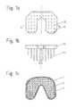
- FIG. 12a shoulder implant in which the humerus component and also the glenoid component are anchored in the described manner;
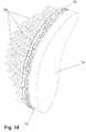
- FIG. 13a first view of the glenoid component of FIG. 12 ;
- FIG. 14a second view of the glenoid component of FIG. 12 ;
- FIG. 15the humerus component of FIG. 12 .
- FIG. 1a tibial plateau 10 is shown in a very simplified representation and is made in the proposed manner.
- FIG. 1 ashows a plan view of the fastening side with which the implant is provided for contact with the resection surface of the bone.
- Anchorage pins 20are arranged on the fastening side of the tibial plateau 10 . They are arranged on a square grid in this Figure, but this is in no way compulsory; any other desired arrangement patterns appropriate for the application are also possible.
- FIG. 1 bshows a view along the line marked by B-B in FIG. 1 a .
- FIG. 1 cshows a plan view of the resection surface of a tibia 1 .
- the cortex 3 at the rim of the resection surfacesubstantially comprises solid bone tissue and is only slightly deformable and is comparatively brittle.
- the bone tissueis, as already described above, composed of bony tissue and medulla and has a greater deformability.
- the proportion of bony tissue in the total tissueis different in different regions of the resection surface.
- the proportion of the bony tissuereduces from the cortex toward the center, whereby the strength also reduces and the deformability of the bone increases. It can be recognized with respect to FIG.
- the length of the anchorage pinsis adapted to this circumstance and is larger in the regions provided for arrangement in regions of the bone with a low proportion of bony tissue than in regions of a high proportion of bony tissue.
- all the anchorage pinsare shown as cylindrical pins having a constant cross-sectional surface.
- the pinscan naturally also be conical in total or regionally or can, for example, converge acutely at the front end remote from the implant. It is equally not compulsory that all the pins have the same cross-sectional shape or longitudinal contour.
- FIG. 2shows an alternative embodiment of such a tibial plateau.
- the anchorage pins 20 on the tibial plateau 10are arranged in a variable density over the surface of the fastening side of the implant.
- the anchorage pins 20are almost of equal length and converge acutely.
- An equivalent effect as is adopted in FIG. 1 due to the longer anchorage pinsis achieved by the reduction of the spacing between the anchorage pins in the regions of the implant which are provided for arrangement on regions of a resection surface with a lower proportion of bony material.
- Anchorage pins of different lengths and other and/or different shapescan naturally also be used in the embodiment shown in FIG. 2 .
- a condyle implant 30is shown schematically in FIG. 3 which has anchorage pins 20 of different lengths for anchorage at the resection surface of a bone.
- FIG. 4The use of an implant of the kind described here at the femoral component of a hip joint prosthesis is shown in FIG. 4 .
- a femoral capis shown in FIGS. 4 a and 4 b as is used for the so-called resurfacing of a femoral head.
- FIG. 4 bis a sectional view of the femoral cap as illustrated in FIG. 4 a taken along line 4 b - 4 b of FIG. 4 a .
- the “resurfacing”is characterized in that as little bone as possible is removed and substantially only the cartilage of the natural articulation surface is replaced by an artificial articulation surface.
- the articulation surface of the femoral cap 40preferably consists of metal, in particular of a steel having a high carbon proportion, which is, however, not material to the invention here.
- the femur 41is shown schematically in FIG. 4 c with the femoral neck 42 , the femoral head 43 and the resection surface 44 at the femoral head.
- the proportion of the bony tissue in the total bone tissueis also different over this resection surface.
- cortexis located at the outer rim of the resection surface into which anchorage pins can only be introduced with difficulty and with the risk also being present of causing a splintering of the cortex with non-predrilled holes for the introduction of the pins.
- spongious material having a large medulla proportionis located at the center of the resection surface.
- the anchorage pins 20 of the femoral cap 40are therefore selected differently in different regions adapted to the bone density and are longer at the center than at the rim, whereas at the far rim, in regions which come to lie on the cortex, no anchorage pins are arranged.
- the fastening of an implant described here by means of a collective of pins adapted to the local bone structure and bone strengthcan naturally also be used in the fastening of the associated acetabulum component.
- a plurality of possible embodiments of anchorage pins 20are shown schematically in FIG. 5 . They extend with a length I starting from the implant 50 . Some of the exemplary anchorage pins 20 have divergent regions seen from the tip toward the implant. The half angle of the divergence is marked by ⁇ . This angle is for example 2°, 3°, 4° or 5°. Small angles, corresponding to very acute pins, facilitate the introduction which in particular takes place into a non-predrilled bone and improve the security of the seat of the pins in the bone. Pins with larger divergence angles, in contrast, have a greater security against kinking on the introduction and facilitate the explantation in any required revisions.
- FIG. 6illustrates further geometrical connections of the arrangement of anchorage pins on the fastening side of an implant.
- the anchorage pins 20are arranged on a grid of equilateral triangles.
- the spacings between the central longitudinal axes of two adjacent anchorage pinsare marked by s.
- the density of the anchorage pinsis the number of pins within a surface element dA and is specified, for example, as the number of pins with respect to a unit of area of, for example, 1 cm 2 .
- FIG. 7illustrates different cross-sectional shapes of anchorage pins. Furthermore, in some of these exemplary anchorage pins, the circumscribed circle 25 is shown with the diameter d.
- FIG. 8illustrates a further embodiment in which wall-like structures 23 whose height h is smaller than the length I of the anchorage pins 20 are arranged between anchorage pins 20 , with the height within such a wall-like structure also being able to be variable, for example such that the height of the wall-like structure is larger adjacent to the anchorage pins than at the center between two anchorage pins; wall-like structures of constant height are naturally also possible or those in which the height is larger at the center between two anchorage pins than adjacent to the anchorage pins.
- the vertical extent of the wall-like structureamounts, for example, to between one millimeter and four millimeters and should be limited such that not too may blood vessels are cut by these wall-like structures within the bone.
- FIG. 9shows a modification of the tibial plateau of FIG. 1 .
- the tibial plateau 10On the fastening side, the tibial plateau 10 has, in addition to the anchorage pins 20 , guide elements 21 which project further from the fastening side than the longest anchorage pin.
- Two positioning bores 4are introduced into the resection surface of the tibia shown in FIG. 9 c and their spacing corresponds to the spacing of the guide elements 21 .
- the guide elements 21On the placement of the tibial plateau onto the resection surface, the guide elements 21 first penetrate into the bores 4 of the tibia and position the tibial plateau there with respect to position and direction before the implant is fixed in the bone by pressing or hammering the anchorage pins into the bone tissue.
- the guide elements 21have a conical tip region in addition to the cylindrical guide region for the easier introduction into the bores 4 .
- the cylindrical guide region of the guide elementsis longer than the longest anchorage pin such that the position and direction of the implant are already securely fixed before the penetration of the anchorage pins.
- FIG. 10shows an exemplary tibial plateau 10 in which the arrangement and geometry of the anchorage pins 20 of the complex bone density distribution is adapted to a real resection surface of a tibia.
- FIG. 11shows this tibial plateau on a tibia 1 in the implanted state.
- a shoulder prosthesisis shown in FIG. 12 in which the components are designed in the manner described and claimed.
- a cap 60which is made, for example, from a metallic material and has an articulation surface 61 is anchored in the humerus 9 by means of anchorage pins 20 of different length. The application of such a cap as a joint surface replacement is likewise actually a “resurfacing” in the manner explained in connection with FIG. 4 .
- a glenoid component 70 having an articulation surface 71is likewise anchored in the scapula 8 by means of a plurality of anchorage pins 20 arranged in a pin field. The surgeon frequently finds very poor bone quality at these points which makes a secure primary fixation of the implants more difficult.
- the distribution of the anchorage over the plurality of pins which are shaped and arranged such that the force is distributed over a bone volume which is the larger, the smaller the local density and stability, of the bone is,has a very advantageous effect. Due to the high porosity of the bone which is often found at the implantation sites, the implantation by pressing in or hammering in the implants is facilitated, whereas the distribution of the holding forces over a number of pins facilitates the primary fixation. A large surface of the pins 20 is available for a secondary fixation by ongrowth on the bone.
- the strength of the hold and the intensity of the connection to the bonecan be influenced in a manner known per se by the geometry of the pins as described above and their surface properties, in particular their roughness.
- the glenoid componentis shown enlarged in FIGS. 13 and 14 .
- itcomprises, in addition to the anchorage pins 20 , an articulation surface 71 which is made, for example, of polyethylene, in particular of a highly cross-linked and/or a high-molecular polyethylene, as well as a multilayer wire mesh 74 which is made, for example, of titanium and is known, for example, under the name “Sulmesh”.
- Thisis very suitable for the anchorage of the polyethylene articulation surface and likewise promotes an ongrowth of the bone.
- FIG. 15shows the humerus component which has the shape of a hollow sphere 60 here and in whose interior the anchorage pins 20 are arranged. The pins are longer at the center of the anchorage surface than at its rim both in the glenoid component 70 and in the humerus component 60 .
- the implantation of the implants described heretakes place in that the corresponding bone is cut.
- the anchorage pinsare pressed into the bone structure of the arising resection surface without corresponding holes having been predrilled.
- boresare introduced for the reception of the spigots and the bone; no bores are introduced for the reception of the spigots and the bone.
- corresponding guide bores and/or centering boreshave to be introduced into the resection surface, in particular by means of a suitable gauge. They are dimensioned, for example, such that they can receive the guide elements and/or centering elements with as little clearance as possible.
- the guide elements and/or centering elementsare then first introduced into the associated bores of the resection surface, whereby the position and/or direction of the implant on the resection surface are defined and the implant is then pressed in or hammered in using the anchorage pins for which no holes were predrilled.
Landscapes
- Health & Medical Sciences (AREA)
- Orthopedic Medicine & Surgery (AREA)
- Life Sciences & Earth Sciences (AREA)
- Animal Behavior & Ethology (AREA)
- General Health & Medical Sciences (AREA)
- Engineering & Computer Science (AREA)
- Biomedical Technology (AREA)
- Heart & Thoracic Surgery (AREA)
- Veterinary Medicine (AREA)
- Public Health (AREA)
- Vascular Medicine (AREA)
- Cardiology (AREA)
- Oral & Maxillofacial Surgery (AREA)
- Transplantation (AREA)
- Surgery (AREA)
- Neurology (AREA)
- Nuclear Medicine, Radiotherapy & Molecular Imaging (AREA)
- Medical Informatics (AREA)
- Molecular Biology (AREA)
- Physical Education & Sports Medicine (AREA)
- Prostheses (AREA)
Abstract
Description
- 1 bone
- 2 spongiosa
- 3 cortex
- 4 bore
- 8 scapula
- 9 humerus
- 10 implant, tibial plateau
- 20 anchorage pin
- 21 guide spigot and/or centering spigot
- 23 areal connection structure, wall-like structure
- 25 circumscribed circle of an anchorage pin
- 30 distal femoral component
- 40 femoral cap
- 41 femur
- 42 femoral neck
- 43 femoral head
- 44 resection surface
- 50 implant
- 60 humerus implant
- 61 articulation surface of the humerus implant
- 70 glenoid implant
- 71 articulation surface of the glenoid implant
- 74 wire mesh structure
- d thickness of an anchorage pin, diameter of the circumscribed circle of an anchorage pin
- dA surface element
- I length of an anchorage pin
- H height of the wall-like structure
- S spacing of two anchorage pins
- α angle
Claims (24)
Applications Claiming Priority (4)
| Application Number | Priority Date | Filing Date | Title |
|---|---|---|---|
| CH18202005 | 2005-11-09 | ||
| CH01820/05 | 2005-11-09 | ||
| CH1820/05 | 2005-11-09 | ||
| PCT/EP2006/068318WO2007054553A1 (en) | 2005-11-09 | 2006-11-09 | Implant |
Publications (2)
| Publication Number | Publication Date |
|---|---|
| US20090105772A1 US20090105772A1 (en) | 2009-04-23 |
| US8308807B2true US8308807B2 (en) | 2012-11-13 |
Family
ID=35840046
Family Applications (1)
| Application Number | Title | Priority Date | Filing Date |
|---|---|---|---|
| US12/162,729Expired - Fee RelatedUS8308807B2 (en) | 2005-11-09 | 2006-11-09 | Implant with differential anchoring |
Country Status (5)
| Country | Link |
|---|---|
| US (1) | US8308807B2 (en) |
| EP (1) | EP1973498B1 (en) |
| AU (1) | AU2006313698B2 (en) |
| CA (1) | CA2640759A1 (en) |
| WO (1) | WO2007054553A1 (en) |
Cited By (15)
| Publication number | Priority date | Publication date | Assignee | Title |
|---|---|---|---|---|
| US9456901B2 (en) | 2004-12-30 | 2016-10-04 | Howmedica Osteonics Corp. | Laser-produced porous structure |
| US9545312B2 (en) | 2004-06-15 | 2017-01-17 | Tornier Sas | Glenoidal component, set of such components and shoulder prosthesis incorporating such a glenoidal component |
| US9629725B2 (en) | 2014-01-03 | 2017-04-25 | Tornier, Inc. | Reverse shoulder systems and methods |
| US10064734B2 (en) | 2011-02-01 | 2018-09-04 | Tornier Sas | Glenoid implant for a shoulder prosthesis, and surgical kit |
| US10398559B2 (en) | 2005-12-06 | 2019-09-03 | Howmedica Osteonics Corp. | Laser-produced porous surface |
| US10614176B2 (en) | 2012-04-06 | 2020-04-07 | Howmedica Osteonics Corp. | Surface modified unit cell lattice structures for optimized secure freeform fabrication |
| US10631993B2 (en) | 2010-10-22 | 2020-04-28 | Tornier, Inc. | Set of glenoid components for a shoulder prosthesis |
| US10722374B2 (en) | 2015-05-05 | 2020-07-28 | Tornier, Inc. | Convertible glenoid implant |
| US10828168B2 (en) | 2017-05-10 | 2020-11-10 | Howmedica Osteonics Corp. | Patient specific composite knee replacement |
| US11155073B2 (en) | 2002-11-08 | 2021-10-26 | Howmedica Osteonics Corp. | Laser-produced porous surface |
| US11160661B2 (en) | 2009-12-14 | 2021-11-02 | Tornier Sas | Shoulder prosthesis glenoid component |
| US11298747B2 (en) | 2017-05-18 | 2022-04-12 | Howmedica Osteonics Corp. | High fatigue strength porous structure |
| US11564802B2 (en) | 2017-10-16 | 2023-01-31 | Imascap Sas | Shoulder implants and assembly |
| US11779471B2 (en) | 2019-08-09 | 2023-10-10 | Howmedica Osteonics Corp. | Apparatuses and methods for implanting glenoid prostheses |
| US12396862B2 (en) | 2019-05-13 | 2025-08-26 | Howmedica Osteonics Corp. | Glenoid baseplate and implant assemblies |
Families Citing this family (48)
| Publication number | Priority date | Publication date | Assignee | Title |
|---|---|---|---|---|
| US6610067B2 (en) | 2000-05-01 | 2003-08-26 | Arthrosurface, Incorporated | System and method for joint resurface repair |
| US6520964B2 (en) | 2000-05-01 | 2003-02-18 | Std Manufacturing, Inc. | System and method for joint resurface repair |
| US8388624B2 (en) | 2003-02-24 | 2013-03-05 | Arthrosurface Incorporated | Trochlear resurfacing system and method |
| WO2006004885A2 (en) | 2004-06-28 | 2006-01-12 | Arthrosurface, Inc. | System for articular surface replacement |
| US9301845B2 (en) | 2005-06-15 | 2016-04-05 | P Tech, Llc | Implant for knee replacement |
| CA2621019A1 (en) | 2005-08-31 | 2007-03-08 | Zimmer Gmbh | Implant |
| CA2641966C (en) | 2005-12-15 | 2016-11-22 | Zimmer, Inc. | Distal femoral knee prostheses |
| WO2007125060A1 (en) | 2006-04-28 | 2007-11-08 | Zimmer Gmbh | Implant |
| US9358029B2 (en) | 2006-12-11 | 2016-06-07 | Arthrosurface Incorporated | Retrograde resection apparatus and method |
| WO2009018128A2 (en) | 2007-07-31 | 2009-02-05 | Zimmer, Inc. | Joint space interpositional prosthetic device with internal bearing surfaces |
| FR2947444B1 (en) | 2009-07-02 | 2012-08-03 | Tornier Sa | BONE AND CARTILAGINOUS RECONSTRUCTION IMPLANT |
| AU2010236182A1 (en) | 2009-04-17 | 2011-11-24 | Arthrosurface Incorporated | Glenoid resurfacing system and method |
| US10945743B2 (en) | 2009-04-17 | 2021-03-16 | Arthrosurface Incorporated | Glenoid repair system and methods of use thereof |
| WO2010121250A1 (en) | 2009-04-17 | 2010-10-21 | Arthrosurface Incorporated | Glenoid resurfacing system and method |
| EP2542165A4 (en) | 2010-03-05 | 2015-10-07 | Arthrosurface Inc | Tibial resurfacing system and method |
| CA2808090C (en)* | 2010-08-12 | 2018-09-11 | Smith & Nephew, Inc. | Structures for use in orthopaedic implant fixation and methods of installation onto a bone |
| CA2993979A1 (en) | 2010-09-10 | 2012-03-15 | Zimmer Gmbh | Femoral prosthesis with medialized patellar groove |
| CA2830197C (en) | 2011-03-25 | 2016-08-09 | Zimmer Gmbh | Shoulder prosthesis |
| US9066716B2 (en) | 2011-03-30 | 2015-06-30 | Arthrosurface Incorporated | Suture coil and suture sheath for tissue repair |
| US8932365B2 (en) | 2011-06-16 | 2015-01-13 | Zimmer, Inc. | Femoral component for a knee prosthesis with improved articular characteristics |
| US9060868B2 (en) | 2011-06-16 | 2015-06-23 | Zimmer, Inc. | Femoral component for a knee prosthesis with bone compacting ridge |
| US9308095B2 (en) | 2011-06-16 | 2016-04-12 | Zimmer, Inc. | Femoral component for a knee prosthesis with improved articular characteristics |
| EP2804565B1 (en) | 2011-12-22 | 2018-03-07 | Arthrosurface Incorporated | System for bone fixation |
| US11304811B2 (en)* | 2012-01-17 | 2022-04-19 | KYOCERA Medical Technologies, Inc. | Surgical implant devices incorporating porous surfaces and associated method of manufacture |
| US20130218284A1 (en)* | 2012-02-16 | 2013-08-22 | Mobius Medical LLC | Tibial baseplate assembly for knee joint prosthesis |
| USD719261S1 (en) | 2012-02-17 | 2014-12-09 | Zimmer Gmbh | Shoulder prosthesis |
| US9135374B2 (en) | 2012-04-06 | 2015-09-15 | Howmedica Osteonics Corp. | Surface modified unit cell lattice structures for optimized secure freeform fabrication |
| WO2014008126A1 (en) | 2012-07-03 | 2014-01-09 | Arthrosurface Incorporated | System and method for joint resurfacing and repair |
| US9265547B2 (en) | 2012-11-14 | 2016-02-23 | Tipirneni Software Llc | Orthopedic bonding agent application tool |
| US9492200B2 (en) | 2013-04-16 | 2016-11-15 | Arthrosurface Incorporated | Suture system and method |
| US9931219B2 (en) | 2014-03-07 | 2018-04-03 | Arthrosurface Incorporated | Implant and anchor assembly |
| US10624748B2 (en) | 2014-03-07 | 2020-04-21 | Arthrosurface Incorporated | System and method for repairing articular surfaces |
| US11607319B2 (en) | 2014-03-07 | 2023-03-21 | Arthrosurface Incorporated | System and method for repairing articular surfaces |
| US10130375B2 (en) | 2014-07-31 | 2018-11-20 | Zimmer, Inc. | Instruments and methods in performing kinematically-aligned total knee arthroplasty |
| GB2540370A (en)* | 2015-07-14 | 2017-01-18 | Imp Innovations Ltd | Prosthetic humeral head component |
| EP3355834B1 (en) | 2015-09-29 | 2023-01-04 | Zimmer, Inc. | Tibial prosthesis for tibia with varus resection |
| US11090161B2 (en)* | 2016-03-25 | 2021-08-17 | Howmedica Osteonics Corp. | Surgical instrumentation assembly, set and surgical shoulder repair method |
| EP3592283B1 (en) | 2017-03-10 | 2024-05-08 | Alps Holding Llc | Hard-tissue implant comprising a bulk implant, a face, pillars, slots, and at least one support member |
| US11324606B2 (en) | 2017-03-10 | 2022-05-10 | Gary A. Zwick | Spinal interbody cage comprising a bulk interbody cage, a top face, a bottom face, pillars, and slots |
| US11160663B2 (en) | 2017-08-04 | 2021-11-02 | Arthrosurface Incorporated | Multicomponent articular surface implant |
| US11278427B2 (en) | 2018-04-10 | 2022-03-22 | Gary A. Zick, Trustee Of The Everest Trust Uta April 20, 2017 | Spinal interbody cage comprising top and bottom faces with mesh structures, pillars and slots |
| WO2020186099A1 (en) | 2019-03-12 | 2020-09-17 | Arthrosurface Incorporated | Humeral and glenoid articular surface implant systems and methods |
| AU2020207869A1 (en)* | 2019-08-01 | 2021-02-18 | Howmedica Osteonics Corp. | Hybrid metal-backed glenoid component |
| JP7335428B2 (en) | 2019-09-11 | 2023-08-29 | アルプス ホールディング エルエルシー | An implant comprising a first set and a second set of pillars for attaching a tendon or ligament to hard tissue |
| PL239580B1 (en)* | 2019-12-02 | 2021-12-13 | Rogala Piotr Indywidualna Specjalistyczna Praktyka Lekarska W Miejscu Wezwania | Endoprosthesis |
| US12144735B2 (en) | 2021-01-27 | 2024-11-19 | b-ONE Medical (Suzhou) Co., Ltd. | Artificial acetabular cup and manufacturing method thereof |
| US20220233318A1 (en)* | 2021-01-27 | 2022-07-28 | b-ONE Medical (Suzhou) Co., Ltd. | Orthopedic implant and manufacturing method thereof |
| US20230210669A1 (en)* | 2022-01-03 | 2023-07-06 | Kyoung Tak KANG | Artificial articulation having stable fixing means for unicompartmental knee arthroplasty |
Citations (138)
| Publication number | Priority date | Publication date | Assignee | Title |
|---|---|---|---|---|
| US1448111A (en) | 1920-02-14 | 1923-03-13 | United Shoe Machinery Corp | Forepart-turning machine |
| DE1164019B (en) | 1960-03-29 | 1964-02-27 | Chiron Werke G M B H | Hip joint head prosthesis and drilling device for its attachment |
| GB1126961A (en) | 1965-01-14 | 1968-09-11 | Nat Res Dev | Artificial joints for use in surgery |
| DE2015324A1 (en) | 1970-03-31 | 1971-11-04 | Timmermans, Dr.med.Dr.Phil. Franz Donatus, 2300 Kiel | Endoprosthesis, preferably for the hip joint, and method for its manufacture |
| DE2501080A1 (en) | 1975-01-13 | 1976-07-15 | Georg Dr Med Patzer | Permanently lubricated joint endoprosthesis - with reduced friction thus preventing excessive wear on prosthesis parts |
| DE2933174A1 (en) | 1978-10-06 | 1980-04-10 | Sulzer Ag | IMPLANT FOR A PARTIAL REPLACEMENT OF A SLIDING SURFACE OF A HUMAN JOINT |
| EP0013864A1 (en) | 1979-01-26 | 1980-08-06 | Osteo Ag | Knee joint slide prosthesis |
| EP0013863A1 (en) | 1979-01-26 | 1980-08-06 | Osteo Ag | Cap prosthesis for cement-free implantation, especially for hip-joint |
| EP0017930A1 (en) | 1979-04-11 | 1980-10-29 | Feldmühle Aktiengesellschaft | Femoral head cap for endoprosthesis |
| DE2953575A1 (en) | 1979-04-11 | 1982-07-08 | Feldmühle AG, 4000 Düsseldorf | Femur cap for hip joint prosthesis - is shaped to grip spherical stump and has grooved, ribbed or roughened interior |
| US4467479A (en) | 1982-02-05 | 1984-08-28 | Brody Garry S | Method of surgically repairing an injured human joint and a prosthetic device therefor |
| GB2139097A (en) | 1983-05-06 | 1984-11-07 | Frederick F Buechel | Implantable joint prosthesis |
| US4502161A (en) | 1981-09-21 | 1985-03-05 | Wall W H | Prosthetic meniscus for the repair of joints |
| EP0170779A1 (en) | 1984-07-02 | 1986-02-12 | GebràDer Sulzer Aktiengesellschaft | Plug-like anchoring for the cement-free fixation of bone implants |
| US4659331A (en)* | 1983-11-28 | 1987-04-21 | Regents Of University Of Michigan | Prosthesis interface surface and method of implanting |
| US4769039A (en) | 1985-09-12 | 1988-09-06 | Sulzer Brothers Limited | Tibial implant for a knee prosthesis |
| US4839215A (en) | 1986-06-09 | 1989-06-13 | Ceramed Corporation | Biocompatible particles and cloth-like article made therefrom |
| US4865603A (en)* | 1988-02-04 | 1989-09-12 | Joint Medical Products Corporation | Metallic prosthetic devices having micro-textured outer surfaces |
| US4896663A (en) | 1988-10-14 | 1990-01-30 | Boehringer Mannheim Corporation | Self centering femoral drill jig |
| US4932969A (en) | 1987-01-08 | 1990-06-12 | Sulzer Brothers Limited | Joint endoprosthesis |
| US4966924A (en) | 1986-02-13 | 1990-10-30 | Biomaterials Universe, Inc. | Soft contact lens and method of manufacturing the same |
| US4976740A (en) | 1989-07-14 | 1990-12-11 | Kleiner Jeffrey B | Anchored femoral dome |
| US5032132A (en)* | 1990-01-22 | 1991-07-16 | Boehringer Mannheim Corporation | Glenoid component |
| US5041138A (en) | 1986-11-20 | 1991-08-20 | Massachusetts Institute Of Technology | Neomorphogenesis of cartilage in vivo from cell culture |
| US5080678A (en) | 1990-03-01 | 1992-01-14 | Sulzer Brothers Limited | Artificial acetabulum |
| US5147904A (en) | 1989-08-24 | 1992-09-15 | Thera Patent Gmbh & Co. Kg | Open-pored moldings, a process for their production and use thereof |
| EP0528080A1 (en) | 1989-12-13 | 1993-02-24 | Stryker Corporation | Articular cartilage repair piece |
| EP0480954B1 (en) | 1989-07-06 | 1993-04-14 | NOLDE, Martin, Dr. | Nucleus prosthesis with an introductory device and probe to determine the size of nucleus prosthesis required |
| US5217498A (en) | 1990-04-04 | 1993-06-08 | S & G Implants Gmbh | Tibial component of a knee joint prosthesis |
| EP0552949A1 (en) | 1992-01-23 | 1993-07-28 | Howmedica International Inc. | Acetabular cup for a total hip prosthesis and total hip prostheses embodying such cups |
| US5246459A (en) | 1992-02-24 | 1993-09-21 | Elias Sarmed G | Modular tibial support pegs for the tibial component of a prosthetic knee replacement system |
| FR2691355A1 (en) | 1992-05-19 | 1993-11-26 | Deux C T | Two-part replacement prosthesis for knee joint tibial surface - has base implanted into upper surface of tibia by downwardly-projecting fasteners, with peripheral groove engaged by separate rubbing block |
| FR2692140A1 (en) | 1992-06-11 | 1993-12-17 | Corum Ste Civile | Partial prosthesis for replacement of knee joint - comprises condylar component implanted into lower end of femur, cooperating with shaped tibial plate supported by bone-embedded metal bar |
| US5271737A (en) | 1992-09-04 | 1993-12-21 | U.S. Medical Products, Inc. | Tibial prosthetic implant with offset stem |
| EP0577529A1 (en) | 1992-06-23 | 1994-01-05 | Medinov Sa | Total sliding prosthesis for the knee |
| US5282861A (en) | 1992-03-11 | 1994-02-01 | Ultramet | Open cell tantalum structures for cancellous bone implants and cell and tissue receptors |
| US5312409A (en) | 1992-06-01 | 1994-05-17 | Mclaughlin Robert E | Drill alignment guide |
| US5314478A (en) | 1991-03-29 | 1994-05-24 | Kyocera Corporation | Artificial bone connection prosthesis |
| US5358525A (en) | 1992-12-28 | 1994-10-25 | Fox John E | Bearing surface for prosthesis and replacement of meniscal cartilage |
| DE4317448A1 (en) | 1993-05-19 | 1994-11-24 | Gross Ulrich | Joint replacement |
| US5370700A (en) | 1993-02-19 | 1994-12-06 | Sarkisian; James S. | Prosthetic knee joint |
| EP0639356A1 (en) | 1993-08-18 | 1995-02-22 | SULZER Medizinaltechnik AG | Process for shaping external anchoring surfaces for joint implants |
| DE29513894U1 (en) | 1995-08-15 | 1995-10-19 | Fa. Ohst u. Sohn, 14712 Rathenow | Shin plateau implant |
| DE3923418C2 (en) | 1989-07-12 | 1995-11-30 | Rolf Prof Dr Miehlke | Endoprosthesis |
| US5556429A (en) | 1994-05-06 | 1996-09-17 | Advanced Bio Surfaces, Inc. | Joint resurfacing system |
| US5607474A (en) | 1992-02-14 | 1997-03-04 | Board Of Regents, University Of Texas System | Multi-phase bioerodible implant/carrier and method of manufacturing and using same |
| US5609641A (en) | 1995-01-31 | 1997-03-11 | Smith & Nephew Richards Inc. | Tibial prosthesis |
| EP0768066A2 (en) | 1995-10-10 | 1997-04-16 | CERASIV GmbH INNOVATIVES KERAMIK-ENGINEERING | Femoral head cap for a hip joint prosthesis |
| US5645592A (en) | 1992-05-20 | 1997-07-08 | M.u.r.s.t. Italian Ministry for Universities and Scientific and Technological Research | Use of hydrogels to fix bone replacements |
| US5658343A (en) | 1994-07-11 | 1997-08-19 | Sulzer Medizinaltechnik Ag | Areal implant |
| WO1997037613A1 (en) | 1996-04-05 | 1997-10-16 | Depuy Orthopaedics, Inc. | Tissue graft construct for replacement of cartilaginous structures |
| US5800551A (en)* | 1997-03-10 | 1998-09-01 | Biomet, Inc. | Apparatus and method for shoulder arthroplasty |
| US5817098A (en) | 1995-05-17 | 1998-10-06 | Astra Aktiebolag | Drill guide instrument |
| DE19721661A1 (en) | 1997-05-23 | 1998-11-26 | Zimmer Markus | Bone and cartilage replacement structures |
| US5871541A (en) | 1993-11-23 | 1999-02-16 | Plus Endoprothetik, Ag | System for producing a knee-joint endoprosthesis |
| DE19803183A1 (en) | 1998-01-28 | 1999-08-19 | Zahedi | Knee joint implant is fixed between tibia and femora by means of tapered pins |
| US5951564A (en) | 1996-12-18 | 1999-09-14 | Bristol-Myers Squibb Company | Orthopaedic positioning apparatus |
| WO2000015153A1 (en) | 1998-09-10 | 2000-03-23 | Mansmann Kevin A | Arthroscopic replacement of cartilage using flexible inflatable envelopes |
| EP0992222A2 (en) | 1998-09-28 | 2000-04-12 | JOHNSON & JOHNSON PROFESSIONAL Inc. | Modular orthopaedic clamping tool |
| WO2000023009A1 (en) | 1998-10-21 | 2000-04-27 | Frauens John T | Apparatus for percutaneous interposition balloon arthroplasty |
| US6140452A (en) | 1994-05-06 | 2000-10-31 | Advanced Bio Surfaces, Inc. | Biomaterial for in situ tissue repair |
| US6168630B1 (en) | 1997-12-30 | 2001-01-02 | Waldemar Link (Gmbh & Co) | Hand joint prosthesis |
| US6224630B1 (en) | 1998-05-29 | 2001-05-01 | Advanced Bio Surfaces, Inc. | Implantable tissue repair device |
| US6231605B1 (en) | 1997-05-05 | 2001-05-15 | Restore Therapeutics | Poly(vinyl alcohol) hydrogel |
| WO2001045595A2 (en) | 1999-12-17 | 2001-06-28 | Cartificial A/S | A prosthetic device |
| FR2803191A1 (en) | 2000-01-04 | 2001-07-06 | Bernard Wirth | Intra-articulatary surgical prosthesis has plastics cup screwed into place and formed of casing separated from multiple layer lining by fluid gap |
| FR2803190A1 (en) | 2000-01-04 | 2001-07-06 | Bernard Wirth | Prosthesis for joints comprises a deformable pocket divided in compartments with doubler and filled with a material |
| EP0507645B1 (en) | 1991-04-03 | 2001-07-11 | Jean-Claude Bouvet | Joint endoprosthesis |
| US6306177B1 (en) | 1994-05-06 | 2001-10-23 | Advanced Bio Surfaces, Inc. | Biomaterial system for in situ tissue repair |
| US20010033857A1 (en) | 1999-06-30 | 2001-10-25 | Vyakarnam Murty N. | Porous tissue scaffoldings for the repair or regeneration of tissue |
| US20010039455A1 (en) | 2000-03-14 | 2001-11-08 | Timothy Simon | Cartilage repair plug |
| DE10021387A1 (en) | 2000-05-03 | 2001-11-22 | Giorgio E Curradini | Femur cap has spherical outer surface with opening, cavity in spherical segment, and opening |
| US20020022884A1 (en) | 2000-03-27 | 2002-02-21 | Mansmann Kevin A. | Meniscus-type implant with hydrogel surface reinforced by three-dimensional mesh |
| US20020029083A1 (en) | 1999-09-13 | 2002-03-07 | Zucherman James F. | Implantable prosthetic or tissue expanding device |
| WO2002041808A1 (en) | 2000-11-22 | 2002-05-30 | Milorad Mitkovic | Insulator of particles created between the articulating components of artificial joints |
| WO2002054992A1 (en) | 2001-01-15 | 2002-07-18 | Artimplant Ab | Implant for reconstruction of joints |
| US6425923B1 (en) | 2000-03-07 | 2002-07-30 | Zimmer, Inc. | Contourable polymer filled implant |
| US6428577B1 (en)* | 1998-05-20 | 2002-08-06 | Smith & Nephew, Inc. | Mobile bearing knee prosthesis |
| US6447514B1 (en) | 2000-03-07 | 2002-09-10 | Zimmer | Polymer filled hip fracture fixation device |
| US20020127264A1 (en) | 2000-08-28 | 2002-09-12 | Felt Jeffrey C. | Method and system for mammalian joint resurfacing |
| US20020161448A1 (en) | 2000-07-20 | 2002-10-31 | Hayes, Jr. Daniel E. E. | Bimetal tibial component construct for knee joint prosthesis |
| US20020173855A1 (en) | 2001-02-05 | 2002-11-21 | Mansmann Kevin A. | Cartilage repair implant with soft bearing surface and flexible anchoring device |
| US20020183845A1 (en) | 2000-11-30 | 2002-12-05 | Mansmann Kevin A. | Multi-perforated non-planar device for anchoring cartilage implants and high-gradient interfaces |
| US20020188300A1 (en) | 2001-06-06 | 2002-12-12 | Arramon Yves P. | Cannula system for hard tissue implant delivery |
| US6494917B1 (en) | 1996-10-15 | 2002-12-17 | Orthopaedic Hospital | Wear resistant surface-gradient crosslinked polyethylene |
| US20020193883A1 (en) | 2001-01-25 | 2002-12-19 | Wironen John F. | Injectable porous bone graft materials |
| US20030008396A1 (en) | 1999-03-17 | 2003-01-09 | Ku David N. | Poly(vinyl alcohol) hydrogel |
| US6530956B1 (en) | 1998-09-10 | 2003-03-11 | Kevin A. Mansmann | Resorbable scaffolds to promote cartilage regeneration |
| US6533818B1 (en) | 2000-04-26 | 2003-03-18 | Pearl Technology Holdings, Llc | Artificial spinal disc |
| US6547828B2 (en) | 2001-02-23 | 2003-04-15 | Smith & Nephew, Inc. | Cross-linked ultra-high molecular weight polyethylene for medical implant use |
| US20030074076A1 (en) | 1999-10-08 | 2003-04-17 | Ferree Bret A. | Artificial intervertebral disc replacements with endplates |
| US20030078617A1 (en) | 2001-07-16 | 2003-04-24 | Schwartz Herbert E. | Unitary surgical device and method |
| DE20303205U1 (en) | 2003-02-21 | 2003-04-30 | Aesculap AG & Co. KG, 78532 Tuttlingen | Device for insertion and fixing of cartilage substituting implant, comprising holding and anchoring element |
| US20030130741A1 (en) | 2002-01-07 | 2003-07-10 | Mcminn Derek James Wallace | Hip prosthesis |
| US20030153918A1 (en) | 2002-02-14 | 2003-08-14 | Putnam Matthew D. | Volar fixation plate |
| EP0892627B1 (en) | 1996-04-12 | 2003-08-20 | Centerpulse Orthopedics Ltd. | Artificial joint |
| US20030163202A1 (en) | 2002-02-06 | 2003-08-28 | Lakin Ryan C. | Modular resurfacing prosthetic |
| US6620196B1 (en) | 2000-08-30 | 2003-09-16 | Sdgi Holdings, Inc. | Intervertebral disc nucleus implants and methods |
| DE10220368A1 (en) | 2002-05-07 | 2003-12-04 | Biotissue Technologies Ag | Implant comprising transplant tissue cells in a porous resorbable matrix, especially useful for cartilage or bone transplantation, includes one or more stiffening elements for increasing compressive stability |
| US20040010312A1 (en) | 2002-07-09 | 2004-01-15 | Albert Enayati | Intervertebral prosthesis |
| US6679913B2 (en) | 1998-04-14 | 2004-01-20 | Tranquil Prospects Ltd. | Implantable sheet material |
| US20040051213A1 (en) | 2000-12-12 | 2004-03-18 | Muratoglu Orhun K. | Selective controlled manipulation of polymers |
| US6719797B1 (en) | 1999-08-13 | 2004-04-13 | Bret A. Ferree | Nucleus augmentation with in situ formed hydrogels |
| EP1407728A1 (en) | 2002-10-07 | 2004-04-14 | Centerpulse Orthopedics Ltd. | Femoral head prosthesis |
| WO2004032987A1 (en) | 2002-10-11 | 2004-04-22 | Cartificial A/S | Medical device comprising a bio-compatible polymeric product with a layered structure |
| US20040133275A1 (en) | 2000-03-27 | 2004-07-08 | Mansmann Kevin A. | Implants for replacing cartilage, with negatively-charged hydrogel surfaces and flexible matrix reinforcement |
| US20040138754A1 (en) | 2002-10-07 | 2004-07-15 | Imaging Therapeutics, Inc. | Minimally invasive joint implant with 3-Dimensional geometry matching the articular surfaces |
| US20040153163A1 (en) | 2003-01-31 | 2004-08-05 | Howmedica Osteonics Corp. | Meniscal and tibial implants |
| US20040163681A1 (en) | 2003-02-25 | 2004-08-26 | Applied Materials, Inc. | Dilute sulfuric peroxide at point-of-use |
| US20040199250A1 (en) | 1999-05-10 | 2004-10-07 | Fell Barry M. | Surgically implantable knee prosthesis |
| US20040220582A1 (en) | 2001-01-12 | 2004-11-04 | Arnold Keller | Surgical instrument for inserting an intervertebral endoprosthesis |
| EP1477120A1 (en) | 2003-05-12 | 2004-11-17 | Corin Limited | Head centering jig for femoral resurfacing |
| US20040236424A1 (en) | 2001-05-25 | 2004-11-25 | Imaging Therapeutics, Inc. | Patient selectable joint arthroplasty devices and surgical tools facilitating increased accuracy, speed and simplicity in performing total and partial joint arthroplasty |
| US6827743B2 (en) | 2001-02-28 | 2004-12-07 | Sdgi Holdings, Inc. | Woven orthopedic implants |
| US20040247641A1 (en) | 2002-01-22 | 2004-12-09 | Felt Jeffrey C. | Interpositional arthroplasty system & method |
| US20050021042A1 (en) | 2003-07-21 | 2005-01-27 | Theirry Marnay | Instruments and method for inserting an intervertebral implant |
| US20050043808A1 (en) | 1994-05-06 | 2005-02-24 | Advanced Bio Surfaces, Inc. | Knee joint prosthesis |
| US20050075642A1 (en) | 2001-12-19 | 2005-04-07 | Felt Jeffrey C. | Bone smoothing method and system |
| DE10339605A1 (en) | 2003-08-28 | 2005-04-14 | Hendrik Priebs | Artificial hip joint has in lieu of cartilage, ball retained in socket by two raised zones that are sewn to socket rim and rim of ball |
| US20050125077A1 (en) | 2003-12-05 | 2005-06-09 | Harmon Alexander M. | Viable tissue repair implants and methods of use |
| WO2005051242A1 (en) | 2003-10-28 | 2005-06-09 | Xiros Plc | Repair of damaged tissue on a bone site |
| US20050171604A1 (en) | 2004-01-20 | 2005-08-04 | Alexander Michalow | Unicondylar knee implant |
| EP1588669A1 (en) | 2004-04-20 | 2005-10-26 | Finsbury (Development) Limited | Alignment guide |
| US20050251266A1 (en) | 2004-05-06 | 2005-11-10 | Maspero Fabrizio A | Biocompatible bone implant compositions and methods for repairing a bone defect |
| US20050251149A1 (en) | 2004-04-27 | 2005-11-10 | Kyphon Inc. | Bone substitute compositions and method of use |
| US20050287187A1 (en) | 2003-10-02 | 2005-12-29 | Mansmann Kevin A | Hydrogel implants for replacing hyaline cartilage, with charged surfaces and improved anchoring |
| US20060009853A1 (en) | 2003-12-30 | 2006-01-12 | Medicinelodge, Inc. | Tethered joint bearing implants and systems |
| US20060079905A1 (en) | 2003-06-17 | 2006-04-13 | Disc-O-Tech Medical Technologies Ltd. | Methods, materials and apparatus for treating bone and other tissue |
| US20060224244A1 (en) | 2005-03-31 | 2006-10-05 | Zimmer Technology, Inc. | Hydrogel implant |
| US20060235542A1 (en) | 2005-04-15 | 2006-10-19 | Zimmer Technology, Inc. | Flexible segmented bearing implant |
| US20070027230A1 (en) | 2004-03-21 | 2007-02-01 | Disc-O-Tech Medical Technologies Ltd. | Methods, materials, and apparatus for treating bone and other tissue |
| US20070088444A1 (en) | 2005-10-13 | 2007-04-19 | Robert A Hodorek | Method for repairing a bone defect using a formable implant which hardens in vivo |
| US20070142916A1 (en) | 2005-12-21 | 2007-06-21 | Olson Stanley W Jr | Bone graft composition, method and implant |
| US20070179607A1 (en) | 2006-01-31 | 2007-08-02 | Zimmer Technology, Inc. | Cartilage resurfacing implant |
| WO2007090790A2 (en) | 2006-02-09 | 2007-08-16 | Zimmer Gmbh | Implant |
| WO2007125060A1 (en) | 2006-04-28 | 2007-11-08 | Zimmer Gmbh | Implant |
| US20080215057A1 (en) | 2005-10-06 | 2008-09-04 | Zimmer Gmbh | Instrument for Preparing and/or Machining a Femoral Head |
| US20080221700A1 (en) | 2005-08-31 | 2008-09-11 | Zimmer, Gmbh | Implant |
Family Cites Families (6)
| Publication number | Priority date | Publication date | Assignee | Title |
|---|---|---|---|---|
| US4996924A (en)* | 1987-08-11 | 1991-03-05 | Mcclain Harry T | Aerodynamic air foil surfaces for in-flight control for projectiles |
| IE960927A1 (en)* | 1996-12-31 | 1998-07-01 | Elan Med Tech | A device for generating a pulsatile fluid drug flow |
| WO2000000515A2 (en)* | 1998-06-29 | 2000-01-06 | Hyseq, Inc. | A CHEMOKINE RECEPTOR OBTAINED FROM A cDNA LIBRARY OF FETAL LIVER-SPLEEN |
| US20040029083A1 (en)* | 2002-08-06 | 2004-02-12 | Coleman Edmund Benedict | Phonemically organized keyboard attached to a speech synthesizer: a machine for teaching the sounds of the letters to young children |
| US6919797B2 (en)* | 2003-03-28 | 2005-07-19 | Hui-Hua Hsieh | Remote-controlled lock |
| US20050255114A1 (en)* | 2003-04-07 | 2005-11-17 | Nuvelo, Inc. | Methods and diagnosis for the treatment of preeclampsia |
- 2006
- 2006-11-09EPEP06819383.8Apatent/EP1973498B1/ennot_activeNot-in-force
- 2006-11-09AUAU2006313698Apatent/AU2006313698B2/ennot_activeCeased
- 2006-11-09WOPCT/EP2006/068318patent/WO2007054553A1/enactiveApplication Filing
- 2006-11-09USUS12/162,729patent/US8308807B2/ennot_activeExpired - Fee Related
- 2006-11-09CACA002640759Apatent/CA2640759A1/ennot_activeAbandoned
Patent Citations (165)
| Publication number | Priority date | Publication date | Assignee | Title |
|---|---|---|---|---|
| US1448111A (en) | 1920-02-14 | 1923-03-13 | United Shoe Machinery Corp | Forepart-turning machine |
| DE1164019B (en) | 1960-03-29 | 1964-02-27 | Chiron Werke G M B H | Hip joint head prosthesis and drilling device for its attachment |
| GB1126961A (en) | 1965-01-14 | 1968-09-11 | Nat Res Dev | Artificial joints for use in surgery |
| DE2015324A1 (en) | 1970-03-31 | 1971-11-04 | Timmermans, Dr.med.Dr.Phil. Franz Donatus, 2300 Kiel | Endoprosthesis, preferably for the hip joint, and method for its manufacture |
| GB1349987A (en) | 1970-03-31 | 1974-04-10 | Timmermans F D | Hipjoint prosthesis |
| DE2501080A1 (en) | 1975-01-13 | 1976-07-15 | Georg Dr Med Patzer | Permanently lubricated joint endoprosthesis - with reduced friction thus preventing excessive wear on prosthesis parts |
| DE2933174A1 (en) | 1978-10-06 | 1980-04-10 | Sulzer Ag | IMPLANT FOR A PARTIAL REPLACEMENT OF A SLIDING SURFACE OF A HUMAN JOINT |
| EP0013863A1 (en) | 1979-01-26 | 1980-08-06 | Osteo Ag | Cap prosthesis for cement-free implantation, especially for hip-joint |
| US4355429A (en)* | 1979-01-26 | 1982-10-26 | Osteo Ag | Slide prosthesis for the knee joint |
| EP0013864A1 (en) | 1979-01-26 | 1980-08-06 | Osteo Ag | Knee joint slide prosthesis |
| EP0017930A1 (en) | 1979-04-11 | 1980-10-29 | Feldmühle Aktiengesellschaft | Femoral head cap for endoprosthesis |
| US4312079A (en) | 1979-04-11 | 1982-01-26 | Feldmuhle Aktiengesellschaft | Femur head cap for endoprosthesis |
| DE2953575A1 (en) | 1979-04-11 | 1982-07-08 | Feldmühle AG, 4000 Düsseldorf | Femur cap for hip joint prosthesis - is shaped to grip spherical stump and has grooved, ribbed or roughened interior |
| US4502161B1 (en) | 1981-09-21 | 1989-07-25 | ||
| US4502161A (en) | 1981-09-21 | 1985-03-05 | Wall W H | Prosthetic meniscus for the repair of joints |
| US4467479A (en) | 1982-02-05 | 1984-08-28 | Brody Garry S | Method of surgically repairing an injured human joint and a prosthetic device therefor |
| GB2139097A (en) | 1983-05-06 | 1984-11-07 | Frederick F Buechel | Implantable joint prosthesis |
| US4659331A (en)* | 1983-11-28 | 1987-04-21 | Regents Of University Of Michigan | Prosthesis interface surface and method of implanting |
| EP0170779A1 (en) | 1984-07-02 | 1986-02-12 | GebràDer Sulzer Aktiengesellschaft | Plug-like anchoring for the cement-free fixation of bone implants |
| US4769039A (en) | 1985-09-12 | 1988-09-06 | Sulzer Brothers Limited | Tibial implant for a knee prosthesis |
| US4966924A (en) | 1986-02-13 | 1990-10-30 | Biomaterials Universe, Inc. | Soft contact lens and method of manufacturing the same |
| US4839215A (en) | 1986-06-09 | 1989-06-13 | Ceramed Corporation | Biocompatible particles and cloth-like article made therefrom |
| US5041138A (en) | 1986-11-20 | 1991-08-20 | Massachusetts Institute Of Technology | Neomorphogenesis of cartilage in vivo from cell culture |
| US4932969A (en) | 1987-01-08 | 1990-06-12 | Sulzer Brothers Limited | Joint endoprosthesis |
| US4865603A (en)* | 1988-02-04 | 1989-09-12 | Joint Medical Products Corporation | Metallic prosthetic devices having micro-textured outer surfaces |
| US4896663A (en) | 1988-10-14 | 1990-01-30 | Boehringer Mannheim Corporation | Self centering femoral drill jig |
| EP0480954B1 (en) | 1989-07-06 | 1993-04-14 | NOLDE, Martin, Dr. | Nucleus prosthesis with an introductory device and probe to determine the size of nucleus prosthesis required |
| DE3923418C2 (en) | 1989-07-12 | 1995-11-30 | Rolf Prof Dr Miehlke | Endoprosthesis |
| US4976740A (en) | 1989-07-14 | 1990-12-11 | Kleiner Jeffrey B | Anchored femoral dome |
| US5147904A (en) | 1989-08-24 | 1992-09-15 | Thera Patent Gmbh & Co. Kg | Open-pored moldings, a process for their production and use thereof |
| EP0528080A1 (en) | 1989-12-13 | 1993-02-24 | Stryker Corporation | Articular cartilage repair piece |
| US5032132A (en)* | 1990-01-22 | 1991-07-16 | Boehringer Mannheim Corporation | Glenoid component |
| US5080678A (en) | 1990-03-01 | 1992-01-14 | Sulzer Brothers Limited | Artificial acetabulum |
| US5217498A (en) | 1990-04-04 | 1993-06-08 | S & G Implants Gmbh | Tibial component of a knee joint prosthesis |
| US5314478A (en) | 1991-03-29 | 1994-05-24 | Kyocera Corporation | Artificial bone connection prosthesis |
| US5458643A (en) | 1991-03-29 | 1995-10-17 | Kyocera Corporation | Artificial intervertebral disc |
| EP0507645B1 (en) | 1991-04-03 | 2001-07-11 | Jean-Claude Bouvet | Joint endoprosthesis |
| EP0552949A1 (en) | 1992-01-23 | 1993-07-28 | Howmedica International Inc. | Acetabular cup for a total hip prosthesis and total hip prostheses embodying such cups |
| US5607474A (en) | 1992-02-14 | 1997-03-04 | Board Of Regents, University Of Texas System | Multi-phase bioerodible implant/carrier and method of manufacturing and using same |
| US5246459A (en) | 1992-02-24 | 1993-09-21 | Elias Sarmed G | Modular tibial support pegs for the tibial component of a prosthetic knee replacement system |
| US5282861A (en) | 1992-03-11 | 1994-02-01 | Ultramet | Open cell tantalum structures for cancellous bone implants and cell and tissue receptors |
| FR2691355A1 (en) | 1992-05-19 | 1993-11-26 | Deux C T | Two-part replacement prosthesis for knee joint tibial surface - has base implanted into upper surface of tibia by downwardly-projecting fasteners, with peripheral groove engaged by separate rubbing block |
| US5645592A (en) | 1992-05-20 | 1997-07-08 | M.u.r.s.t. Italian Ministry for Universities and Scientific and Technological Research | Use of hydrogels to fix bone replacements |
| US5312409A (en) | 1992-06-01 | 1994-05-17 | Mclaughlin Robert E | Drill alignment guide |
| FR2692140A1 (en) | 1992-06-11 | 1993-12-17 | Corum Ste Civile | Partial prosthesis for replacement of knee joint - comprises condylar component implanted into lower end of femur, cooperating with shaped tibial plate supported by bone-embedded metal bar |
| EP0577529A1 (en) | 1992-06-23 | 1994-01-05 | Medinov Sa | Total sliding prosthesis for the knee |
| USRE37277E1 (en) | 1992-09-04 | 2001-07-10 | Hayes Medical, Inc. | Tibial prosthetic implant with offset stem |
| US5271737A (en) | 1992-09-04 | 1993-12-21 | U.S. Medical Products, Inc. | Tibial prosthetic implant with offset stem |
| US5358525A (en) | 1992-12-28 | 1994-10-25 | Fox John E | Bearing surface for prosthesis and replacement of meniscal cartilage |
| US5370700A (en) | 1993-02-19 | 1994-12-06 | Sarkisian; James S. | Prosthetic knee joint |
| DE4317448A1 (en) | 1993-05-19 | 1994-11-24 | Gross Ulrich | Joint replacement |
| US5553476A (en) | 1993-08-18 | 1996-09-10 | Sulzer Medizinaltechnik Ag | Process for the production of outer attachment faces on joint implants |
| EP0639356A1 (en) | 1993-08-18 | 1995-02-22 | SULZER Medizinaltechnik AG | Process for shaping external anchoring surfaces for joint implants |
| US5871541A (en) | 1993-11-23 | 1999-02-16 | Plus Endoprothetik, Ag | System for producing a knee-joint endoprosthesis |
| US7077865B2 (en) | 1994-05-06 | 2006-07-18 | Disc Dynamics, Inc. | Method of making an intervertebral disc prosthesis |
| US6140452A (en) | 1994-05-06 | 2000-10-31 | Advanced Bio Surfaces, Inc. | Biomaterial for in situ tissue repair |
| US20020156531A1 (en) | 1994-05-06 | 2002-10-24 | Felt Jeffrey C. | Biomaterial system for in situ tissue repair |
| US5795353A (en) | 1994-05-06 | 1998-08-18 | Advanced Bio Surfaces, Inc. | Joint resurfacing system |
| US7001431B2 (en) | 1994-05-06 | 2006-02-21 | Disc Dynamics, Inc. | Intervertebral disc prosthesis |
| US6443988B2 (en) | 1994-05-06 | 2002-09-03 | Disc Dynamics, Inc. | Mold apparatus and kit for in situ tissue repair |
| US20060253200A1 (en) | 1994-05-06 | 2006-11-09 | Disc Dynamics, Inc. | Method of making an intervertebral disc prosthesis |
| US20050043808A1 (en) | 1994-05-06 | 2005-02-24 | Advanced Bio Surfaces, Inc. | Knee joint prosthesis |
| US20030195628A1 (en) | 1994-05-06 | 2003-10-16 | Qi-Bin Bao | Method of making an intervertebral disc prosthesis |
| US5556429A (en) | 1994-05-06 | 1996-09-17 | Advanced Bio Surfaces, Inc. | Joint resurfacing system |
| US20070038300A1 (en) | 1994-05-06 | 2007-02-15 | Disc Dynamics, Inc. | Intervertebral disc prosthesis |
| US6306177B1 (en) | 1994-05-06 | 2001-10-23 | Advanced Bio Surfaces, Inc. | Biomaterial system for in situ tissue repair |
| US20030220649A1 (en) | 1994-05-06 | 2003-11-27 | Qi-Bin Bao | Intervertebral disc prosthesis |
| US5658343A (en) | 1994-07-11 | 1997-08-19 | Sulzer Medizinaltechnik Ag | Areal implant |
| US5609641A (en) | 1995-01-31 | 1997-03-11 | Smith & Nephew Richards Inc. | Tibial prosthesis |
| US5817098A (en) | 1995-05-17 | 1998-10-06 | Astra Aktiebolag | Drill guide instrument |
| DE29513894U1 (en) | 1995-08-15 | 1995-10-19 | Fa. Ohst u. Sohn, 14712 Rathenow | Shin plateau implant |
| EP0768066A2 (en) | 1995-10-10 | 1997-04-16 | CERASIV GmbH INNOVATIVES KERAMIK-ENGINEERING | Femoral head cap for a hip joint prosthesis |
| WO1997037613A1 (en) | 1996-04-05 | 1997-10-16 | Depuy Orthopaedics, Inc. | Tissue graft construct for replacement of cartilaginous structures |
| EP0892627B1 (en) | 1996-04-12 | 2003-08-20 | Centerpulse Orthopedics Ltd. | Artificial joint |
| EP1340477A2 (en) | 1996-04-12 | 2003-09-03 | Centerpulse Orthopedics Ltd. | Method for producing a bearing shell and a ball head of an artifical joint |
| US6494917B1 (en) | 1996-10-15 | 2002-12-17 | Orthopaedic Hospital | Wear resistant surface-gradient crosslinked polyethylene |
| US5951564A (en) | 1996-12-18 | 1999-09-14 | Bristol-Myers Squibb Company | Orthopaedic positioning apparatus |
| US5800551A (en)* | 1997-03-10 | 1998-09-01 | Biomet, Inc. | Apparatus and method for shoulder arthroplasty |
| US6231605B1 (en) | 1997-05-05 | 2001-05-15 | Restore Therapeutics | Poly(vinyl alcohol) hydrogel |
| DE19721661A1 (en) | 1997-05-23 | 1998-11-26 | Zimmer Markus | Bone and cartilage replacement structures |
| US6168630B1 (en) | 1997-12-30 | 2001-01-02 | Waldemar Link (Gmbh & Co) | Hand joint prosthesis |
| DE19803183A1 (en) | 1998-01-28 | 1999-08-19 | Zahedi | Knee joint implant is fixed between tibia and femora by means of tapered pins |
| US6679913B2 (en) | 1998-04-14 | 2004-01-20 | Tranquil Prospects Ltd. | Implantable sheet material |
| US20040267371A1 (en) | 1998-05-14 | 2004-12-30 | Hayes Daniel E. E. | Bimetal tibial component construct for knee joint prosthesis |
| US6428577B1 (en)* | 1998-05-20 | 2002-08-06 | Smith & Nephew, Inc. | Mobile bearing knee prosthesis |
| US6224630B1 (en) | 1998-05-29 | 2001-05-01 | Advanced Bio Surfaces, Inc. | Implantable tissue repair device |
| WO2000015153A1 (en) | 1998-09-10 | 2000-03-23 | Mansmann Kevin A | Arthroscopic replacement of cartilage using flexible inflatable envelopes |
| US6132468A (en) | 1998-09-10 | 2000-10-17 | Mansmann; Kevin A. | Arthroscopic replacement of cartilage using flexible inflatable envelopes |
| US6530956B1 (en) | 1998-09-10 | 2003-03-11 | Kevin A. Mansmann | Resorbable scaffolds to promote cartilage regeneration |
| EP0992222A2 (en) | 1998-09-28 | 2000-04-12 | JOHNSON & JOHNSON PROFESSIONAL Inc. | Modular orthopaedic clamping tool |
| WO2000023009A1 (en) | 1998-10-21 | 2000-04-27 | Frauens John T | Apparatus for percutaneous interposition balloon arthroplasty |
| US20030008396A1 (en) | 1999-03-17 | 2003-01-09 | Ku David N. | Poly(vinyl alcohol) hydrogel |
| US20040199250A1 (en) | 1999-05-10 | 2004-10-07 | Fell Barry M. | Surgically implantable knee prosthesis |
| US20010033857A1 (en) | 1999-06-30 | 2001-10-25 | Vyakarnam Murty N. | Porous tissue scaffoldings for the repair or regeneration of tissue |
| US6719797B1 (en) | 1999-08-13 | 2004-04-13 | Bret A. Ferree | Nucleus augmentation with in situ formed hydrogels |
| US20020029083A1 (en) | 1999-09-13 | 2002-03-07 | Zucherman James F. | Implantable prosthetic or tissue expanding device |
| US20030074076A1 (en) | 1999-10-08 | 2003-04-17 | Ferree Bret A. | Artificial intervertebral disc replacements with endplates |
| WO2001045595A2 (en) | 1999-12-17 | 2001-06-28 | Cartificial A/S | A prosthetic device |
| FR2803190A1 (en) | 2000-01-04 | 2001-07-06 | Bernard Wirth | Prosthesis for joints comprises a deformable pocket divided in compartments with doubler and filled with a material |
| FR2803191A1 (en) | 2000-01-04 | 2001-07-06 | Bernard Wirth | Intra-articulatary surgical prosthesis has plastics cup screwed into place and formed of casing separated from multiple layer lining by fluid gap |
| US6447514B1 (en) | 2000-03-07 | 2002-09-10 | Zimmer | Polymer filled hip fracture fixation device |
| US6425923B1 (en) | 2000-03-07 | 2002-07-30 | Zimmer, Inc. | Contourable polymer filled implant |
| US20040039447A1 (en) | 2000-03-14 | 2004-02-26 | Ultra Tec Manufacturing, Inc. | Cartilage repair plug |
| US20010039455A1 (en) | 2000-03-14 | 2001-11-08 | Timothy Simon | Cartilage repair plug |
| US20020022884A1 (en) | 2000-03-27 | 2002-02-21 | Mansmann Kevin A. | Meniscus-type implant with hydrogel surface reinforced by three-dimensional mesh |
| US6629997B2 (en) | 2000-03-27 | 2003-10-07 | Kevin A. Mansmann | Meniscus-type implant with hydrogel surface reinforced by three-dimensional mesh |
| US20040133275A1 (en) | 2000-03-27 | 2004-07-08 | Mansmann Kevin A. | Implants for replacing cartilage, with negatively-charged hydrogel surfaces and flexible matrix reinforcement |
| US6533818B1 (en) | 2000-04-26 | 2003-03-18 | Pearl Technology Holdings, Llc | Artificial spinal disc |
| DE10021387A1 (en) | 2000-05-03 | 2001-11-22 | Giorgio E Curradini | Femur cap has spherical outer surface with opening, cavity in spherical segment, and opening |
| US20020161448A1 (en) | 2000-07-20 | 2002-10-31 | Hayes, Jr. Daniel E. E. | Bimetal tibial component construct for knee joint prosthesis |
| US6652588B2 (en) | 2000-07-20 | 2003-11-25 | Hayes Medical, Inc. | Bimetal tibial component construct for knee joint prosthesis |
| US20020183850A1 (en) | 2000-08-28 | 2002-12-05 | Felt Jeffrey C. | Method and system for mammalian joint resurfacing |
| US20020173852A1 (en) | 2000-08-28 | 2002-11-21 | Felt Jeffrey C. | Method and system for mammalian joint resurfacing |
| US20040107000A1 (en) | 2000-08-28 | 2004-06-03 | Felt Jeffrey C. | Method and system for mammalian joint resurfacing |
| US20020127264A1 (en) | 2000-08-28 | 2002-09-12 | Felt Jeffrey C. | Method and system for mammalian joint resurfacing |
| US6652587B2 (en) | 2000-08-28 | 2003-11-25 | Advanced Bio Surfaces, Inc. | Method and system for mammalian joint resurfacing |
| US6620196B1 (en) | 2000-08-30 | 2003-09-16 | Sdgi Holdings, Inc. | Intervertebral disc nucleus implants and methods |
| WO2002041808A1 (en) | 2000-11-22 | 2002-05-30 | Milorad Mitkovic | Insulator of particles created between the articulating components of artificial joints |
| US20020183845A1 (en) | 2000-11-30 | 2002-12-05 | Mansmann Kevin A. | Multi-perforated non-planar device for anchoring cartilage implants and high-gradient interfaces |
| US20040051213A1 (en) | 2000-12-12 | 2004-03-18 | Muratoglu Orhun K. | Selective controlled manipulation of polymers |
| US20040220582A1 (en) | 2001-01-12 | 2004-11-04 | Arnold Keller | Surgical instrument for inserting an intervertebral endoprosthesis |
| WO2002054992A1 (en) | 2001-01-15 | 2002-07-18 | Artimplant Ab | Implant for reconstruction of joints |
| US20020193883A1 (en) | 2001-01-25 | 2002-12-19 | Wironen John F. | Injectable porous bone graft materials |
| US20020173855A1 (en) | 2001-02-05 | 2002-11-21 | Mansmann Kevin A. | Cartilage repair implant with soft bearing surface and flexible anchoring device |
| US6547828B2 (en) | 2001-02-23 | 2003-04-15 | Smith & Nephew, Inc. | Cross-linked ultra-high molecular weight polyethylene for medical implant use |
| US6827743B2 (en) | 2001-02-28 | 2004-12-07 | Sdgi Holdings, Inc. | Woven orthopedic implants |
| US20040236424A1 (en) | 2001-05-25 | 2004-11-25 | Imaging Therapeutics, Inc. | Patient selectable joint arthroplasty devices and surgical tools facilitating increased accuracy, speed and simplicity in performing total and partial joint arthroplasty |
| US20020188300A1 (en) | 2001-06-06 | 2002-12-12 | Arramon Yves P. | Cannula system for hard tissue implant delivery |
| US20030078617A1 (en) | 2001-07-16 | 2003-04-24 | Schwartz Herbert E. | Unitary surgical device and method |
| US20050075642A1 (en) | 2001-12-19 | 2005-04-07 | Felt Jeffrey C. | Bone smoothing method and system |
| US20030130741A1 (en) | 2002-01-07 | 2003-07-10 | Mcminn Derek James Wallace | Hip prosthesis |
| US20040247641A1 (en) | 2002-01-22 | 2004-12-09 | Felt Jeffrey C. | Interpositional arthroplasty system & method |
| US20030163202A1 (en) | 2002-02-06 | 2003-08-28 | Lakin Ryan C. | Modular resurfacing prosthetic |
| US20030153918A1 (en) | 2002-02-14 | 2003-08-14 | Putnam Matthew D. | Volar fixation plate |
| DE10220368A1 (en) | 2002-05-07 | 2003-12-04 | Biotissue Technologies Ag | Implant comprising transplant tissue cells in a porous resorbable matrix, especially useful for cartilage or bone transplantation, includes one or more stiffening elements for increasing compressive stability |
| US20040010312A1 (en) | 2002-07-09 | 2004-01-15 | Albert Enayati | Intervertebral prosthesis |
| US20040138754A1 (en) | 2002-10-07 | 2004-07-15 | Imaging Therapeutics, Inc. | Minimally invasive joint implant with 3-Dimensional geometry matching the articular surfaces |
| EP1407728A1 (en) | 2002-10-07 | 2004-04-14 | Centerpulse Orthopedics Ltd. | Femoral head prosthesis |
| WO2004032987A1 (en) | 2002-10-11 | 2004-04-22 | Cartificial A/S | Medical device comprising a bio-compatible polymeric product with a layered structure |
| US6994730B2 (en) | 2003-01-31 | 2006-02-07 | Howmedica Osteonics Corp. | Meniscal and tibial implants |
| US20040153163A1 (en) | 2003-01-31 | 2004-08-05 | Howmedica Osteonics Corp. | Meniscal and tibial implants |
| DE20303205U1 (en) | 2003-02-21 | 2003-04-30 | Aesculap AG & Co. KG, 78532 Tuttlingen | Device for insertion and fixing of cartilage substituting implant, comprising holding and anchoring element |
| US20040163681A1 (en) | 2003-02-25 | 2004-08-26 | Applied Materials, Inc. | Dilute sulfuric peroxide at point-of-use |
| EP1477120A1 (en) | 2003-05-12 | 2004-11-17 | Corin Limited | Head centering jig for femoral resurfacing |
| US20060079905A1 (en) | 2003-06-17 | 2006-04-13 | Disc-O-Tech Medical Technologies Ltd. | Methods, materials and apparatus for treating bone and other tissue |
| US20050021042A1 (en) | 2003-07-21 | 2005-01-27 | Theirry Marnay | Instruments and method for inserting an intervertebral implant |
| DE10339605A1 (en) | 2003-08-28 | 2005-04-14 | Hendrik Priebs | Artificial hip joint has in lieu of cartilage, ball retained in socket by two raised zones that are sewn to socket rim and rim of ball |
| US20050287187A1 (en) | 2003-10-02 | 2005-12-29 | Mansmann Kevin A | Hydrogel implants for replacing hyaline cartilage, with charged surfaces and improved anchoring |
| WO2005051242A1 (en) | 2003-10-28 | 2005-06-09 | Xiros Plc | Repair of damaged tissue on a bone site |
| US20050125077A1 (en) | 2003-12-05 | 2005-06-09 | Harmon Alexander M. | Viable tissue repair implants and methods of use |
| US20060009853A1 (en) | 2003-12-30 | 2006-01-12 | Medicinelodge, Inc. | Tethered joint bearing implants and systems |
| US20050171604A1 (en) | 2004-01-20 | 2005-08-04 | Alexander Michalow | Unicondylar knee implant |
| US20070027230A1 (en) | 2004-03-21 | 2007-02-01 | Disc-O-Tech Medical Technologies Ltd. | Methods, materials, and apparatus for treating bone and other tissue |
| EP1588669A1 (en) | 2004-04-20 | 2005-10-26 | Finsbury (Development) Limited | Alignment guide |
| US20050251149A1 (en) | 2004-04-27 | 2005-11-10 | Kyphon Inc. | Bone substitute compositions and method of use |
| US20050251266A1 (en) | 2004-05-06 | 2005-11-10 | Maspero Fabrizio A | Biocompatible bone implant compositions and methods for repairing a bone defect |
| US20060224244A1 (en) | 2005-03-31 | 2006-10-05 | Zimmer Technology, Inc. | Hydrogel implant |
| US20060235542A1 (en) | 2005-04-15 | 2006-10-19 | Zimmer Technology, Inc. | Flexible segmented bearing implant |
| US20080221700A1 (en) | 2005-08-31 | 2008-09-11 | Zimmer, Gmbh | Implant |
| US20080215057A1 (en) | 2005-10-06 | 2008-09-04 | Zimmer Gmbh | Instrument for Preparing and/or Machining a Femoral Head |
| US20070088444A1 (en) | 2005-10-13 | 2007-04-19 | Robert A Hodorek | Method for repairing a bone defect using a formable implant which hardens in vivo |
| US20070142916A1 (en) | 2005-12-21 | 2007-06-21 | Olson Stanley W Jr | Bone graft composition, method and implant |
| US20070179607A1 (en) | 2006-01-31 | 2007-08-02 | Zimmer Technology, Inc. | Cartilage resurfacing implant |
| WO2007090790A2 (en) | 2006-02-09 | 2007-08-16 | Zimmer Gmbh | Implant |
| WO2007125060A1 (en) | 2006-04-28 | 2007-11-08 | Zimmer Gmbh | Implant |
Non-Patent Citations (1)
| Title |
|---|
| Quinton, J.S. and P.C. Dastoor, "Characterizing the bonding mechanisms at silane-metal interfaces: a model system", J. Mat. Sci. Letters, vol. 18, Nov. 1999, pp. 1833-1835. |
Cited By (34)
| Publication number | Priority date | Publication date | Assignee | Title |
|---|---|---|---|---|
| US11186077B2 (en) | 2002-11-08 | 2021-11-30 | Howmedica Osteonics Corp. | Laser-produced porous surface |
| US11155073B2 (en) | 2002-11-08 | 2021-10-26 | Howmedica Osteonics Corp. | Laser-produced porous surface |
| US11510783B2 (en) | 2002-11-08 | 2022-11-29 | Howmedica Osteonics Corp. | Laser-produced porous surface |
| US9545312B2 (en) | 2004-06-15 | 2017-01-17 | Tornier Sas | Glenoidal component, set of such components and shoulder prosthesis incorporating such a glenoidal component |
| US11523907B2 (en) | 2004-06-15 | 2022-12-13 | Tornier Sas | Glenoidal component, set of such components and shoulder prosthesis incorporating such a glenoidal component |
| US10610363B2 (en) | 2004-06-15 | 2020-04-07 | Tornier Sas | Glenoidal component, set of such components and shoulder prosthesis incorporating such a glenoidal component |
| US9456901B2 (en) | 2004-12-30 | 2016-10-04 | Howmedica Osteonics Corp. | Laser-produced porous structure |
| US11660195B2 (en) | 2004-12-30 | 2023-05-30 | Howmedica Osteonics Corp. | Laser-produced porous structure |
| US11918474B2 (en) | 2005-12-06 | 2024-03-05 | The University Of Liverpool | Laser-produced porous surface |
| US10716673B2 (en) | 2005-12-06 | 2020-07-21 | Howmedica Osteonics Corp. | Laser-produced porous surface |
| US10398559B2 (en) | 2005-12-06 | 2019-09-03 | Howmedica Osteonics Corp. | Laser-produced porous surface |
| US12011355B2 (en) | 2005-12-06 | 2024-06-18 | Howmedica Osteonics Corp. | Laser-produced porous surface |
| US11160661B2 (en) | 2009-12-14 | 2021-11-02 | Tornier Sas | Shoulder prosthesis glenoid component |
| US10631993B2 (en) | 2010-10-22 | 2020-04-28 | Tornier, Inc. | Set of glenoid components for a shoulder prosthesis |
| US11304815B2 (en) | 2010-10-22 | 2022-04-19 | Howmedica Osteonics Corp. | Set of glenoid components for a shoulder prosthesis |
| US11877933B2 (en) | 2011-02-01 | 2024-01-23 | Tornier Sas | Glenoid implant for a shoulder prosthesis, and surgical kit |
| US10918492B2 (en) | 2011-02-01 | 2021-02-16 | Tornier Sas | Glenoid implant for a shoulder prosthesis, and surgical kit |
| US12290447B2 (en) | 2011-02-01 | 2025-05-06 | Tornier Sas | Glenoid implant for a shoulder prosthesis, and surgical kit |
| US10064734B2 (en) | 2011-02-01 | 2018-09-04 | Tornier Sas | Glenoid implant for a shoulder prosthesis, and surgical kit |
| US12102538B2 (en) | 2012-04-06 | 2024-10-01 | Howmedica Osteonics Corp. | Surface modified unit cell lattice structures for optimized secure freeform fabrication |
| US10614176B2 (en) | 2012-04-06 | 2020-04-07 | Howmedica Osteonics Corp. | Surface modified unit cell lattice structures for optimized secure freeform fabrication |
| US11759323B2 (en) | 2012-04-06 | 2023-09-19 | Howmedica Osteonics Corp. | Surface modified unit cell lattice structures for optimized secure freeform fabrication |
| US12144739B2 (en) | 2014-01-03 | 2024-11-19 | Howmedica Osteonics Corp. | Reverse shoulder systems and methods |
| US10357373B2 (en) | 2014-01-03 | 2019-07-23 | Tornier, Inc. | Reverse shoulder systems and methods |
| US11103357B2 (en) | 2014-01-03 | 2021-08-31 | Howmedica Osteonics Corp. | Reverse shoulder systems and methods |
| US9629725B2 (en) | 2014-01-03 | 2017-04-25 | Tornier, Inc. | Reverse shoulder systems and methods |
| US10722374B2 (en) | 2015-05-05 | 2020-07-28 | Tornier, Inc. | Convertible glenoid implant |
| US10828168B2 (en) | 2017-05-10 | 2020-11-10 | Howmedica Osteonics Corp. | Patient specific composite knee replacement |
| US11298747B2 (en) | 2017-05-18 | 2022-04-12 | Howmedica Osteonics Corp. | High fatigue strength porous structure |
| US11684478B2 (en) | 2017-05-18 | 2023-06-27 | Howmedica Osteonics Corp. | High fatigue strength porous structure |
| US11564802B2 (en) | 2017-10-16 | 2023-01-31 | Imascap Sas | Shoulder implants and assembly |
| US12396862B2 (en) | 2019-05-13 | 2025-08-26 | Howmedica Osteonics Corp. | Glenoid baseplate and implant assemblies |
| US11779471B2 (en) | 2019-08-09 | 2023-10-10 | Howmedica Osteonics Corp. | Apparatuses and methods for implanting glenoid prostheses |
| US12329659B2 (en) | 2019-08-09 | 2025-06-17 | Howmedica Osteonics Corp. | Apparatuses and methods for implanting glenoid prostheses |
Also Published As
| Publication number | Publication date |
|---|---|
| WO2007054553A1 (en) | 2007-05-18 |
| AU2006313698A2 (en) | 2009-02-26 |
| US20090105772A1 (en) | 2009-04-23 |
| CA2640759A1 (en) | 2007-05-18 |
| EP1973498A1 (en) | 2008-10-01 |
| EP1973498B1 (en) | 2014-04-23 |
| AU2006313698B2 (en) | 2012-07-26 |
| AU2006313698A1 (en) | 2007-05-18 |
Similar Documents
| Publication | Publication Date | Title |
|---|---|---|
| US8308807B2 (en) | Implant with differential anchoring | |
| US5702477A (en) | Acetabular shell with supplemental support and method | |
| US7497876B2 (en) | Prosthetic implant | |
| US4659331A (en) | Prosthesis interface surface and method of implanting | |
| EP2689751B1 (en) | Cement pressurizing glenoid | |
| US9474619B2 (en) | Glenoid component with improved fixation stability | |
| US5163961A (en) | Compression-fit hip prosthesis and procedures for implantation thereof | |
| US8021432B2 (en) | Apparatus for use of porous implants | |
| AU2002336155B2 (en) | Modular acetabular cup, and anchoring screw for fixing a prosthetic implant such as said acetabular cup | |
| US7753959B2 (en) | Modular center pegged glenoid | |
| EP1467681B1 (en) | Hip joint and shoulder joint endoprothesis | |
| US20090062923A1 (en) | Method and apparatus for shoulder arthroplasty | |
| US20080195221A1 (en) | Implant and a method for partial replacement of joint surfaces | |
| EP2564814A1 (en) | Stemless shoulder implant assembly | |
| EP2002804A1 (en) | Single entry portal implant | |
| AU2020410261A1 (en) | Replacement member for a joint replacement | |
| JP2005506876A (en) | Prosthesis | |
| WO2007082810A2 (en) | Modular revision socket for hip-joint prosthesis and anchoring pin therefor | |
| KR102788835B1 (en) | Acetabular Cup with Porous Layer for Improved Fixation | |
| WO2024187135A2 (en) | Universal humeral stem | |
| HK1108349A1 (en) | Endoprosthetic elements for an ankle joint | |
| HK1067293B (en) | Modular acetabular cup |
Legal Events
| Date | Code | Title | Description |
|---|---|---|---|
| AS | Assignment | Owner name:ZIMMER, GMBH, SWITZERLAND Free format text:ASSIGNMENT OF ASSIGNORS INTEREST;ASSIGNORS:SEEBECK, JORN;SIGGELKOW, EIK;SIGNING DATES FROM 20080811 TO 20080815;REEL/FRAME:021440/0855 Owner name:ZIMMER, GMBH, SWITZERLAND Free format text:ASSIGNMENT OF ASSIGNORS INTEREST;ASSIGNORS:SEEBECK, JORN;SIGGELKOW, EIK;REEL/FRAME:021440/0855;SIGNING DATES FROM 20080811 TO 20080815 | |
| FEPP | Fee payment procedure | Free format text:PAYOR NUMBER ASSIGNED (ORIGINAL EVENT CODE: ASPN); ENTITY STATUS OF PATENT OWNER: LARGE ENTITY | |
| ZAAA | Notice of allowance and fees due | Free format text:ORIGINAL CODE: NOA | |
| ZAAB | Notice of allowance mailed | Free format text:ORIGINAL CODE: MN/=. | |
| STCF | Information on status: patent grant | Free format text:PATENTED CASE | |
| CC | Certificate of correction | ||
| FPAY | Fee payment | Year of fee payment:4 | |
| MAFP | Maintenance fee payment | Free format text:PAYMENT OF MAINTENANCE FEE, 8TH YEAR, LARGE ENTITY (ORIGINAL EVENT CODE: M1552); ENTITY STATUS OF PATENT OWNER: LARGE ENTITY Year of fee payment:8 | |
| LAPS | Lapse for failure to pay maintenance fees | Free format text:PATENT EXPIRED FOR FAILURE TO PAY MAINTENANCE FEES (ORIGINAL EVENT CODE: EXP.); ENTITY STATUS OF PATENT OWNER: LARGE ENTITY | |
| STCH | Information on status: patent discontinuation | Free format text:PATENT EXPIRED DUE TO NONPAYMENT OF MAINTENANCE FEES UNDER 37 CFR 1.362 | |
| FP | Lapsed due to failure to pay maintenance fee | Effective date:20241113 |