US8308773B2 - Pedicle screw - Google Patents
Pedicle screwDownload PDFInfo
- Publication number
- US8308773B2 US8308773B2US11/993,814US99381406AUS8308773B2US 8308773 B2US8308773 B2US 8308773B2US 99381406 AUS99381406 AUS 99381406AUS 8308773 B2US8308773 B2US 8308773B2
- Authority
- US
- United States
- Prior art keywords
- locking bolt
- threaded portion
- head
- pedicle screw
- groove
- Prior art date
- Legal status (The legal status is an assumption and is not a legal conclusion. Google has not performed a legal analysis and makes no representation as to the accuracy of the status listed.)
- Active, expires
Links
- 210000000988bone and boneAnatomy0.000claimsdescription20
- 238000010276constructionMethods0.000description2
- 230000003111delayed effectEffects0.000description1
- 230000000694effectsEffects0.000description1
- 238000012986modificationMethods0.000description1
- 230000004048modificationEffects0.000description1
- 238000011084recoveryMethods0.000description1
Images


Classifications
- A—HUMAN NECESSITIES
- A61—MEDICAL OR VETERINARY SCIENCE; HYGIENE
- A61B—DIAGNOSIS; SURGERY; IDENTIFICATION
- A61B17/00—Surgical instruments, devices or methods
- A61B17/56—Surgical instruments or methods for treatment of bones or joints; Devices specially adapted therefor
- A61B17/58—Surgical instruments or methods for treatment of bones or joints; Devices specially adapted therefor for osteosynthesis, e.g. bone plates, screws or setting implements
- A61B17/68—Internal fixation devices, including fasteners and spinal fixators, even if a part thereof projects from the skin
- A61B17/70—Spinal positioners or stabilisers, e.g. stabilisers comprising fluid filler in an implant
- A61B17/7001—Screws or hooks combined with longitudinal elements which do not contact vertebrae
- A61B17/7032—Screws or hooks with U-shaped head or back through which longitudinal rods pass
- A—HUMAN NECESSITIES
- A61—MEDICAL OR VETERINARY SCIENCE; HYGIENE
- A61B—DIAGNOSIS; SURGERY; IDENTIFICATION
- A61B17/00—Surgical instruments, devices or methods
- A61B17/56—Surgical instruments or methods for treatment of bones or joints; Devices specially adapted therefor
- A61B17/58—Surgical instruments or methods for treatment of bones or joints; Devices specially adapted therefor for osteosynthesis, e.g. bone plates, screws or setting implements
- A61B17/68—Internal fixation devices, including fasteners and spinal fixators, even if a part thereof projects from the skin
- A61B17/70—Spinal positioners or stabilisers, e.g. stabilisers comprising fluid filler in an implant
- A—HUMAN NECESSITIES
- A61—MEDICAL OR VETERINARY SCIENCE; HYGIENE
- A61B—DIAGNOSIS; SURGERY; IDENTIFICATION
- A61B17/00—Surgical instruments, devices or methods
- A61B17/56—Surgical instruments or methods for treatment of bones or joints; Devices specially adapted therefor
- A61B17/58—Surgical instruments or methods for treatment of bones or joints; Devices specially adapted therefor for osteosynthesis, e.g. bone plates, screws or setting implements
- A61B17/68—Internal fixation devices, including fasteners and spinal fixators, even if a part thereof projects from the skin
- A61B17/74—Devices for the head or neck or trochanter of the femur
Definitions
- the present inventionrelates to a pedicle screw, and more particularly, to a pedicle screw, in which by changing the structure of a threaded portion of a locking bolt engaged with a head of the pedicle screw and forming a groove on the locking bolt, the threaded portion is pressed in a fastening direction of the locking bolt, so that when a head of the pedicle screw is fastened to the locking bolt, a fixation cap is not released by the force applied from the head expanding towards an outside, and thus the locking bolt is easily fastened to the head of a screw body, thereby improving an inefficiency factor such as delay of surgical operation time due to release or interference of the fixation cap.
- a patient suffered from injured portion of spinal bonesdoes not carry himself or herself in such a state. Even though a patient having a weak damage acts, the damaged spinal bone compresses adjacent spinal bone or comes into contact with adjacent spinal bone, thereby causing a pain in the patient. In addition, although the patient is placed under medical care, the recovery is delayed.
- the patient suffered from the ruptured or damaged spinal bonehas a surgical operation on the adjacent spinal bones by supporting the damage spinal bone with an artificial prosthetic device so as to prevent the damaged spinal bone from being pressed or expanded.
- Such an artificial prosthetic deviceconsists of pedicle screws inserted into upper and lower portions of the damaged spinal bone to serve as a fixation, and a rod engaged to the pedicle screw to serve as a support.
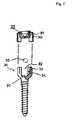
- FIG. 7illustrates the structure of a conventional artificial prosthetic device.
- a pedicle screw 30has an opening 32 formed on an upper portion of a head engaging groove 31 , and a threaded portion 34 formed on inner surfaces or outer surfaces of support walls 33 provided on both sides of the opening.
- the support pipe 36 of an engaging member 35is placed on the outer surface of the support wall 33 , and then, a male threaded part 37 is threadedly engaged with the threaded portion.
- the rod 20in case the rod 20 is inserted at an inclined angle, the rod 20 should be pressed against the head engaging groove 31 by using a separate guide tool, so that the engaging member 35 can be engaged to the pedicle screw by means of a screw and a ring or a cap.
- the rod 20should be forcibly held in the engaging groove 31 by using the separate guide tool before the male threaded part 37 of the engaging member 35 is threadedly engaged with the threaded portion of the engaging groove 31 .
- the rodcan be pre-engaged by the male threaded part 37 .
- the weak fastening force of the threaded portion of the support wallcan be complemented by the screw, the outer ring or the cap used on the outer portion of the engaging member. Since the use of the outer ring or cap increases a width of the engaging member, it may cause the interference between the components in a narrow space on the operation.
- the present inventionis directed to a pedicle screw that substantially obviates one or more problems due to limitations and disadvantages of the related art.
- An object of the present inventionis to provide a pedicle screw, in which by adjusting a thread angle of threaded portions formed on a locking bolt and a head of the pedicle screw and forming a groove on the locking bolt, the locking bolt is not released from the head, in which a fixation cap is not required to prevent the interference of a rod, in which a volume of the head is reduced, and in which the locking bolt is easily fastened to the pedicle screw, thereby improving precision and inefficiency factors such as delay of surgical operation time due to release or interference of the fixation cap.
- a pedicle screwincluding a screw body threadedly engaged with spinal bones at regular interval to support a rod against the spinal bone so as to prevent a damaged portion of the spinal bone from being expanded or pressed, the screw body having a head on an upper end of the screw body, a seat groove formed on a center portion of the head, an upper portion and both sides of the seat groove being opened, and a female threaded portion formed on an inner surface of the seat groove, and a locking bolt having a male threaded portion formed on an outer periphery thereof which is threadedly engaged with the female threaded portion to support the rod installed on the head of the screw body, wherein a groove is formed to have a predetermined depth on the outer periphery of the locking bolt in a spiral direction, so that the male threaded portion of the locking bolt closely contacts the female threaded portion of the head when the locking bolt is threadedly engaged with the head, so as to prevent the locking bolt
- the grooveis formed to have a depth equal to a half of a diameter of the locking bolt.
- the female threaded portion formed on the head and the male threaded portion formed on the locking bolthave a corresponding inversed-trapezoidal cross section.
- the shape and design of the female threaded portion formed on the head of the screw body and male threaded portion of the locking bolt, and the groove formed on the locking boltcan prevent the release of the head, and easily rigidly fix the pedicle screw, without using a cap.
- FIG. 1is a perspective view illustrating the construction of a pedicle screw according to the present invention
- FIG. 2is a front cross-sectional view illustrating the engaged state of a pedicle screw according to the present invention
- FIG. 3is an enlarged cross-sectional view of the portion “A” in FIG. 2 ;
- FIG. 4is a view illustrating only a locking bolt of a pedicle screw according to the present invention.
- FIG. 5is a cross-sectional view taken along a line I-I in FIG. 4 ;
- FIG. 6is a perspective view illustrating the installed state of a pedicle screw according to the present invention.
- FIG. 7is an exploded perspective view illustrating a conventional pedicle screw according to the present invention.
- FIG. 1is a perspective view illustrating the construction of a pedicle screw according to the present invention.
- FIG. 2is a front cross-sectional view illustrating the engaged state of the pedicle screw according to the present invention.
- FIG. 3is an enlarged cross-sectional view of the portion “A” in FIG. 2 .
- FIG. 4is a view illustrating only a locking bolt of a pedicle screw according to the present invention.
- FIG. 5is a cross-sectional view taken along a line I-I in FIG. 4 .
- FIG. 6is a perspective view illustrating the installed state of a pedicle screw according to the present invention.
- the pedicle screwincludes a screw body 110 .
- the screw bodies 110are threadedly engaged with spinal bones at regular intervals.
- the screw body 110has a head 110 a on an upper end of the screw body, a seat groove 114 formed on a center portion of the head 110 a , an upper portion and both sides of the seat groove being opened, and a female threaded portion 112 formed on an inner surface of the seat groove 114 .
- a rod 130is installed on the seat groove 114 formed on the head 110 a of the screw body 110 , and has a locking bolt 120 for locking and supporting the rod 130 .
- a male threaded portion 122is formed on an outer periphery of the locking bolt 120 , and is threadedly engaged with the female threaded portion 112 formed on the head 110 a of the screw body 110 .
- the female threaded portion 112 and the male threaded portion 122have a corresponding inversed-trapezoidal shape so that the threaded portions are interconnected. The reason is to prevent the locking bolt 120 from being released from the head 100 a.
- the present inventionis characterized in that the groove 124 is formed on the locking bolt 120 .
- the locking boltis not released from the head 110 a by the groove 124 . More specifically, the male threaded portion 122 formed on the locking bolt 120 is pressed towards one side of the female threaded portion 112 formed on the head 110 a , and then, the threaded portions are engaged to each other to prevent the locking bolt 120 from being released from the head 110 a.
- the groove 124is formed to have a predetermined depth on the outer periphery of the locking bolt 120 in a spiral direction. Consequently, the male threaded portion 122 formed on the locking bolt 120 is pressed towards one side of the female threaded portion 112 formed on the head 110 a , and then, the threaded portions are engaged to each other to prevent the locking bolt 120 from being released from the head 110 a .
- the groove 124may be formed to have a depth equal to a half of a diameter of the locking bolt 120 , but the present invention is not limited thereto. For example, the groove may be formed to have a depth equal to 1 ⁇ 3 of the diameter of the locking bolt 120 .
- the groovemay be formed to have a depth in such a way that the male threaded portion 122 formed on the locking bolt 120 is pressed toward one direction by the groove 120 .
- the groove 124is generally planar and extends radially inwardly from the male threaded portion 122 (male threads) and has a height less than the pitch of the male threaded portion 122 .
- the groove 124can also be configured to extend through a body of the locking bolt 120 in a chord-like fashion and angled relative to a longitudinal axis of the body.
- the screw bodies 110are threadedly engaged with the spinal bones at a regular interval.
- the rod 130is inserted into the groove 114 formed on the head 110 a of the screw body 110 .
- the rodis fixed by the locking bolt 120 , thereby interconnecting the screw bodies 110 installed on the spinal bones at a regular interval.
- the female threaded portion 112 and the male threaded portion 122 formed on the head 110 a of the screw body 110 which are engaged to each otherhave an inversed-trapezoidal shape, so as to prevent the male threaded portion 122 of the locking bolt 120 from being released from the female threaded portion 112 of the head 110 a .
- the head 110 a of the screw body 110does not rotate, and the head 110 a and the rod 130 are rigidly fixed by the locking bolt 120 .
- the pedicle screw of the present inventioncan be more rigidly fixed by the groove 124 formed on the locking bolt 120 .
- the force resulted from a bottom the locking bolt abutting the rod 130is transferred to the male threaded portion 122 in a direction perpendicular to the fastening direction of the locking bolt 120 through the groove 124 . Consequently, one surface of the male threaded portion 122 is closely engaged with the female threaded portion 112 , thereby preventing the locking bolt 120 from being released from the head.
- the female threaded portion 112 and the male threaded portion 122 formed on the head 110 a of the screw body 110 which are engaged to each otherhave an inversed-trapezoidal shape, and the groove 124 is formed on the locking bolt 120 , so that the threaded portion are rigidly engaged with each other so as to prevent locking bolt 120 from being released from the head 110 a.
- FIG. 6is a perspective view illustrating the installed state of the pedicle screw according to the present invention.
- the screw body 110is threadedly engaged with the spinal bone, and the rod 114 is inserted into the seat groove 114 formed on the head 110 a of the screw body 110 . Then, the locking bolt 120 is fastened to the head 110 a . At that time, the locking bolt 120 is turned to easily fix the rod 130 .
- the design of the female threaded portion 112 formed on the head 110 a of the screw body 110 and male threaded portion 122 of the locking bolt 120 and the groove formed on the locking bolt 120can prevent the release of the locking bolt from the groove 124 , so that a cap is not needed.
- the shape and design of the female threaded portion formed on the head of the screw body and male threaded portion of the locking bolt, and the groove formed on the locking boltcan prevent the release of the head, and easily rigidly fix the pedicle screw, without using a cap.
Landscapes
- Health & Medical Sciences (AREA)
- Orthopedic Medicine & Surgery (AREA)
- Life Sciences & Earth Sciences (AREA)
- Surgery (AREA)
- Neurology (AREA)
- Heart & Thoracic Surgery (AREA)
- Engineering & Computer Science (AREA)
- Biomedical Technology (AREA)
- Nuclear Medicine, Radiotherapy & Molecular Imaging (AREA)
- Medical Informatics (AREA)
- Molecular Biology (AREA)
- Animal Behavior & Ethology (AREA)
- General Health & Medical Sciences (AREA)
- Public Health (AREA)
- Veterinary Medicine (AREA)
- Surgical Instruments (AREA)
- Prostheses (AREA)
Abstract
Description
Claims (10)
Applications Claiming Priority (3)
| Application Number | Priority Date | Filing Date | Title |
|---|---|---|---|
| KR2020050035851UKR200410476Y1 (en) | 2005-12-21 | 2005-12-21 | Pedicle screw |
| KR20-2005-0035851 | 2005-12-21 | ||
| PCT/KR2006/005477WO2007073059A2 (en) | 2005-12-21 | 2006-12-14 | Pedicle screw |
Publications (2)
| Publication Number | Publication Date |
|---|---|
| US20100087874A1 US20100087874A1 (en) | 2010-04-08 |
| US8308773B2true US8308773B2 (en) | 2012-11-13 |
Family
ID=38189094
Family Applications (1)
| Application Number | Title | Priority Date | Filing Date |
|---|---|---|---|
| US11/993,814Active2029-10-03US8308773B2 (en) | 2005-12-21 | 2006-12-14 | Pedicle screw |
Country Status (4)
| Country | Link |
|---|---|
| US (1) | US8308773B2 (en) |
| JP (1) | JP3148465U (en) |
| KR (1) | KR200410476Y1 (en) |
| WO (1) | WO2007073059A2 (en) |
Cited By (1)
| Publication number | Priority date | Publication date | Assignee | Title |
|---|---|---|---|---|
| US20160361094A1 (en)* | 2015-06-15 | 2016-12-15 | Aesculap Ag | Pedicle screw with radially offset guideway |
Families Citing this family (6)
| Publication number | Priority date | Publication date | Assignee | Title |
|---|---|---|---|---|
| CN101502439B (en)* | 2009-03-10 | 2012-02-22 | 李明 | Vertebral pedicle screw with locking screw thread on tail section |
| DE102012219350A1 (en)* | 2012-10-18 | 2014-04-24 | Silony Medical International AG | osteosynthesis |
| JP2014210082A (en)* | 2013-04-19 | 2014-11-13 | サンエー精工株式会社 | Bone fixing screw set |
| US10786289B2 (en)* | 2014-07-16 | 2020-09-29 | The Regents Of The University Of Colorado A Body Corporate | System and methods for positioning of two or more interacting elements |
| KR101882097B1 (en) | 2016-11-04 | 2018-07-27 | 울산대학교 산학협력단 | Method of making protection plate for spinal surgery |
| KR101866378B1 (en) | 2016-11-04 | 2018-06-14 | 서울대학교병원 | Protection plate for spinal surgery |
Citations (73)
| Publication number | Priority date | Publication date | Assignee | Title |
|---|---|---|---|---|
| US1352765A (en)* | 1920-02-06 | 1920-09-14 | Sevigne Henri Alfred | Lock-nut |
| US4887596A (en) | 1988-03-02 | 1989-12-19 | Synthes (U.S.A.) | Open backed pedicle screw |
| US4917409A (en) | 1983-04-29 | 1990-04-17 | Hydril Company | Tubular connection |
| US5154719A (en) | 1990-02-19 | 1992-10-13 | Societe De Fabrication De Materiel Orthopedique - Sofamor | Implant for a device for osteosynthesis, in particular of the spine |
| US5176680A (en) | 1990-02-08 | 1993-01-05 | Vignaud Jean Louis | Device for the adjustable fixing of spinal osteosynthesis rods |
| US5217497A (en) | 1990-07-04 | 1993-06-08 | Mehdian Seyed M H | Apparatus for use in the treatment of spinal disorders |
| US5306275A (en) | 1992-12-31 | 1994-04-26 | Bryan Donald W | Lumbar spine fixation apparatus and method |
| US5360431A (en) | 1990-04-26 | 1994-11-01 | Cross Medical Products | Transpedicular screw system and method of use |
| US5443467A (en) | 1993-03-10 | 1995-08-22 | Biedermann Motech Gmbh | Bone screw |
| US5466237A (en) | 1993-11-19 | 1995-11-14 | Cross Medical Products, Inc. | Variable locking stabilizer anchor seat and screw |
| US5486174A (en) | 1993-02-24 | 1996-01-23 | Soprane S.A. | Fastener for the osteosynthesis of the spinal column |
| US5520689A (en) | 1992-06-04 | 1996-05-28 | Synthes (U.S.A.) | Osteosynthetic fastening device |
| US5536268A (en) | 1992-12-23 | 1996-07-16 | Plus Endoprothetik Ag | System for osteosynthesis at the vertebral column, connecting element for such a system and tool for its placement and removal |
| US5669911A (en) | 1995-04-13 | 1997-09-23 | Fastenetix, L.L.C. | Polyaxial pedicle screw |
| US5683390A (en) | 1994-02-22 | 1997-11-04 | Howmedica Gmbh | Correcting a spinal column |
| US5702443A (en)* | 1993-04-27 | 1997-12-30 | Medevelop Ab | Anchoring element for implantation in tissue, for holding prostheses, artificial joint components or the like |
| US5738685A (en) | 1993-05-18 | 1998-04-14 | Schafer Micomed Gmbh | Osteosynthesis device |
| US5752957A (en) | 1997-02-12 | 1998-05-19 | Third Millennium Engineering, Llc | Polyaxial mechanism for use with orthopaedic implant devices |
| US5782833A (en) | 1996-12-20 | 1998-07-21 | Haider; Thomas T. | Pedicle screw system for osteosynthesis |
| US5876403A (en) | 1996-09-06 | 1999-03-02 | Robert Reid Inc. | Bone-fixing devices |
| US5989254A (en) | 1997-05-20 | 1999-11-23 | Katz; Akiva Raphael | Pedicle screw assembly |
| US6074391A (en) | 1997-06-16 | 2000-06-13 | Howmedica Gmbh | Receiving part for a retaining component of a vertebral column implant |
| US6113601A (en) | 1998-06-12 | 2000-09-05 | Bones Consulting, Llc | Polyaxial pedicle screw having a loosely coupled locking cap |
| US6139549A (en) | 1996-04-09 | 2000-10-31 | Waldemar Link (Gmbh & Co.) | Spinal fixing device |
| US6254146B1 (en) | 1999-04-23 | 2001-07-03 | John Gandy Corporation | Thread form with multifacited flanks |
| US6302888B1 (en) | 1999-03-19 | 2001-10-16 | Interpore Cross International | Locking dovetail and self-limiting set screw assembly for a spinal stabilization member |
| JP2002052030A (en) | 2000-08-07 | 2002-02-19 | Peter Muller | Stem screw |
| US6402752B2 (en) | 2000-02-07 | 2002-06-11 | Ulrich Gmbh & Co. Kg | Polyaxial pedicle-screw |
| US20020138076A1 (en)* | 2000-12-27 | 2002-09-26 | Biederman Motech Gmbh | Screw |
| KR20030015826A (en) | 2002-06-26 | 2003-02-25 | 삼성테크윈 주식회사 | Spinal fixation system |
| US6537276B2 (en) | 1992-03-02 | 2003-03-25 | Stryker Trauma Gmbh | Apparatus for bracing vertebrae |
| US20030100904A1 (en)* | 2001-11-27 | 2003-05-29 | Lutz Biedermann | Locking device for securing a rod-shaped element in a holding element connected to a shank |
| US6626908B2 (en) | 2000-07-22 | 2003-09-30 | Corin Spinal Systems Limited | Pedicle attachment assembly |
| US6641586B2 (en) | 2002-02-01 | 2003-11-04 | Depuy Acromed, Inc. | Closure system for spinal fixation instrumentation |
| US6692500B2 (en) | 2001-10-15 | 2004-02-17 | Gary Jack Reed | Orthopedic stabilization device and method |
| US6723100B2 (en) | 2001-07-27 | 2004-04-20 | Biedermann Motech Gmbh | Bone screw and fastening tool for same |
| US20040082956A1 (en)* | 2000-08-02 | 2004-04-29 | Orthopaedic Biosystems Ltd, Inc. A Delaware Corporation | Medical screw and method of installation |
| US6736820B2 (en) | 2000-11-10 | 2004-05-18 | Biedermann Motech Gmbh | Bone screw |
| US20040158247A1 (en) | 2003-02-07 | 2004-08-12 | Arthit Sitiso | Polyaxial pedicle screw system |
| US20040172022A1 (en) | 2002-10-30 | 2004-09-02 | Landry Michael E. | Bone fastener assembly for a spinal stabilization system |
| US6835196B2 (en) | 2001-03-27 | 2004-12-28 | Biedermann Motech Gmbh | Anchoring element |
| US20050049589A1 (en) | 2003-08-28 | 2005-03-03 | Jackson Roger P. | Polyaxial bone screw apparatus |
| US6869433B2 (en) | 2001-01-12 | 2005-03-22 | Depuy Acromed, Inc. | Polyaxial screw with improved locking |
| US20050131406A1 (en) | 2003-12-15 | 2005-06-16 | Archus Orthopedics, Inc. | Polyaxial adjustment of facet joint prostheses |
| US6974460B2 (en) | 2001-09-14 | 2005-12-13 | Stryker Spine | Biased angulation bone fixation assembly |
| US20060009773A1 (en) | 2002-09-06 | 2006-01-12 | Jackson Roger P | Helical interlocking mating guide and advancement structure |
| US20060025767A1 (en) | 2002-11-04 | 2006-02-02 | Khalili Farid B | Orthopedic rod system |
| US20060058794A1 (en) | 2002-09-06 | 2006-03-16 | Jackson Roger P | Helical guide and advancement flange with break-off extensions |
| US20060229615A1 (en) | 2005-02-18 | 2006-10-12 | Abdou M S | Devices and methods for dynamic fixation of skeletal structure |
| US20060247631A1 (en) | 2005-04-27 | 2006-11-02 | Ahn Sae Y | Spinal pedicle screw assembly |
| US20070093818A1 (en) | 2005-08-03 | 2007-04-26 | Lutz Biedermann | Bone anchoring device |
| US7214227B2 (en) | 2004-03-22 | 2007-05-08 | Innovative Spinal Technologies | Closure member for a medical implant device |
| US7377923B2 (en) | 2003-05-22 | 2008-05-27 | Alphatec Spine, Inc. | Variable angle spinal screw assembly |
| US20080177322A1 (en) | 2006-12-29 | 2008-07-24 | Melissa Davis | Spinal stabilization systems and methods |
| US20080234752A1 (en) | 2007-03-21 | 2008-09-25 | The University Of North Carolina At Chapel Hill | Surgical plate puller devices and methods for use with surgical bone screw/plate systems |
| US20080288002A1 (en) | 2006-12-29 | 2008-11-20 | Abbott Spine Inc. | Spinal Stabilization Systems and Methods |
| US20090005815A1 (en) | 2007-06-28 | 2009-01-01 | Scott Ely | Dynamic stabilization system |
| US20090005814A1 (en) | 2007-06-28 | 2009-01-01 | Peter Thomas Miller | Stabilization system and method |
| US20090093843A1 (en) | 2007-10-05 | 2009-04-09 | Lemoine Jeremy J | Dynamic spine stabilization system |
| US20090163961A1 (en) | 2007-12-19 | 2009-06-25 | X-Spine Systems, Inc. | Offset multiaxial or polyaxial screw, system and assembly |
| US20090163956A1 (en) | 2007-12-13 | 2009-06-25 | Lutz Biedermann | Anchoring device for anchoring a rod in bones or vertebrae |
| US20090228050A1 (en) | 2004-11-03 | 2009-09-10 | Jackson Roger P | Polyaxial bone screw |
| US7588575B2 (en) | 2003-10-21 | 2009-09-15 | Innovative Spinal Technologies | Extension for use with stabilization systems for internal structures |
| US20090306722A1 (en) | 2003-03-17 | 2009-12-10 | Lewis Edward L | Connector for attaching an alignment rod to a bone structure |
| US20100004694A1 (en) | 2008-07-01 | 2010-01-07 | Alphatec Spine, Inc. | Screw assembly |
| US7662172B2 (en) | 2004-10-25 | 2010-02-16 | X-Spine Systems, Inc. | Pedicle screw systems and methods of assembling/installing the same |
| US7678137B2 (en) | 2004-01-13 | 2010-03-16 | Life Spine, Inc. | Pedicle screw constructs for spine fixation systems |
| US20100094353A1 (en) | 2008-10-09 | 2010-04-15 | Korea Bone Bank, Inc. | Pedicle screw |
| US20100131018A1 (en) | 2003-06-27 | 2010-05-27 | Depuy Spine, Inc. | Polyaxial bone screw |
| US20100198273A1 (en) | 2005-10-21 | 2010-08-05 | Kwak Seungkyu Daniel | Adjustable bone screw assembly |
| US20100234904A1 (en) | 2009-03-10 | 2010-09-16 | Marc Evan Richelsoph | Active Bone Screw |
| US7828829B2 (en) | 2006-03-22 | 2010-11-09 | Pioneer Surgical Technology Inc. | Low top bone fixation system and method for using the same |
| US7837716B2 (en) | 2000-08-23 | 2010-11-23 | Jackson Roger P | Threadform for medical implant closure |
- 2005
- 2005-12-21KRKR2020050035851Upatent/KR200410476Y1/ennot_activeExpired - Lifetime
- 2006
- 2006-12-14WOPCT/KR2006/005477patent/WO2007073059A2/enactiveApplication Filing
- 2006-12-14USUS11/993,814patent/US8308773B2/enactiveActive
- 2006-12-14JPJP2008600029Upatent/JP3148465U/ennot_activeExpired - Lifetime
Patent Citations (90)
| Publication number | Priority date | Publication date | Assignee | Title |
|---|---|---|---|---|
| US1352765A (en)* | 1920-02-06 | 1920-09-14 | Sevigne Henri Alfred | Lock-nut |
| US4917409A (en) | 1983-04-29 | 1990-04-17 | Hydril Company | Tubular connection |
| US4887596A (en) | 1988-03-02 | 1989-12-19 | Synthes (U.S.A.) | Open backed pedicle screw |
| US5176680A (en) | 1990-02-08 | 1993-01-05 | Vignaud Jean Louis | Device for the adjustable fixing of spinal osteosynthesis rods |
| US5154719A (en) | 1990-02-19 | 1992-10-13 | Societe De Fabrication De Materiel Orthopedique - Sofamor | Implant for a device for osteosynthesis, in particular of the spine |
| US5360431A (en) | 1990-04-26 | 1994-11-01 | Cross Medical Products | Transpedicular screw system and method of use |
| US5474555A (en) | 1990-04-26 | 1995-12-12 | Cross Medical Products | Spinal implant system |
| US5217497A (en) | 1990-07-04 | 1993-06-08 | Mehdian Seyed M H | Apparatus for use in the treatment of spinal disorders |
| US7128743B2 (en) | 1992-03-02 | 2006-10-31 | Stryker Trauma Gmbh | Apparatus for bracing vertebrae |
| US6537276B2 (en) | 1992-03-02 | 2003-03-25 | Stryker Trauma Gmbh | Apparatus for bracing vertebrae |
| US20060084996A1 (en) | 1992-03-02 | 2006-04-20 | Stryker Trauma Gmbh | Apparatus for bracing vertebrae |
| US20100198264A1 (en) | 1992-03-02 | 2010-08-05 | Stryker Trauma Gmbh | Apparatus for bracing vertebrae |
| US5520689A (en) | 1992-06-04 | 1996-05-28 | Synthes (U.S.A.) | Osteosynthetic fastening device |
| US5536268A (en) | 1992-12-23 | 1996-07-16 | Plus Endoprothetik Ag | System for osteosynthesis at the vertebral column, connecting element for such a system and tool for its placement and removal |
| US5306275A (en) | 1992-12-31 | 1994-04-26 | Bryan Donald W | Lumbar spine fixation apparatus and method |
| US5486174A (en) | 1993-02-24 | 1996-01-23 | Soprane S.A. | Fastener for the osteosynthesis of the spinal column |
| US5443467A (en) | 1993-03-10 | 1995-08-22 | Biedermann Motech Gmbh | Bone screw |
| US5702443A (en)* | 1993-04-27 | 1997-12-30 | Medevelop Ab | Anchoring element for implantation in tissue, for holding prostheses, artificial joint components or the like |
| US5738685A (en) | 1993-05-18 | 1998-04-14 | Schafer Micomed Gmbh | Osteosynthesis device |
| US5466237A (en) | 1993-11-19 | 1995-11-14 | Cross Medical Products, Inc. | Variable locking stabilizer anchor seat and screw |
| US5683390A (en) | 1994-02-22 | 1997-11-04 | Howmedica Gmbh | Correcting a spinal column |
| US5669911A (en) | 1995-04-13 | 1997-09-23 | Fastenetix, L.L.C. | Polyaxial pedicle screw |
| US6139549A (en) | 1996-04-09 | 2000-10-31 | Waldemar Link (Gmbh & Co.) | Spinal fixing device |
| US5876403A (en) | 1996-09-06 | 1999-03-02 | Robert Reid Inc. | Bone-fixing devices |
| US6565567B1 (en) | 1996-12-20 | 2003-05-20 | Thomas T. Haider | Pedicle screw for osteosynthesis |
| US5782833A (en) | 1996-12-20 | 1998-07-21 | Haider; Thomas T. | Pedicle screw system for osteosynthesis |
| US5752957A (en) | 1997-02-12 | 1998-05-19 | Third Millennium Engineering, Llc | Polyaxial mechanism for use with orthopaedic implant devices |
| US5989254A (en) | 1997-05-20 | 1999-11-23 | Katz; Akiva Raphael | Pedicle screw assembly |
| US6074391A (en) | 1997-06-16 | 2000-06-13 | Howmedica Gmbh | Receiving part for a retaining component of a vertebral column implant |
| US6113601A (en) | 1998-06-12 | 2000-09-05 | Bones Consulting, Llc | Polyaxial pedicle screw having a loosely coupled locking cap |
| US6302888B1 (en) | 1999-03-19 | 2001-10-16 | Interpore Cross International | Locking dovetail and self-limiting set screw assembly for a spinal stabilization member |
| US6254146B1 (en) | 1999-04-23 | 2001-07-03 | John Gandy Corporation | Thread form with multifacited flanks |
| US6402752B2 (en) | 2000-02-07 | 2002-06-11 | Ulrich Gmbh & Co. Kg | Polyaxial pedicle-screw |
| US6626908B2 (en) | 2000-07-22 | 2003-09-30 | Corin Spinal Systems Limited | Pedicle attachment assembly |
| US20040082956A1 (en)* | 2000-08-02 | 2004-04-29 | Orthopaedic Biosystems Ltd, Inc. A Delaware Corporation | Medical screw and method of installation |
| JP2002052030A (en) | 2000-08-07 | 2002-02-19 | Peter Muller | Stem screw |
| US7837716B2 (en) | 2000-08-23 | 2010-11-23 | Jackson Roger P | Threadform for medical implant closure |
| US6736820B2 (en) | 2000-11-10 | 2004-05-18 | Biedermann Motech Gmbh | Bone screw |
| US20060106383A1 (en) | 2000-11-10 | 2006-05-18 | Biedermann Motech Gmbh | Bone screw |
| US7018378B2 (en) | 2000-12-27 | 2006-03-28 | Biedermann Motech Gmbh | Screw |
| US20070055238A1 (en) | 2000-12-27 | 2007-03-08 | Biedermann Motech Gmbh | Screw |
| US20020138076A1 (en)* | 2000-12-27 | 2002-09-26 | Biederman Motech Gmbh | Screw |
| US7291153B2 (en) | 2001-01-12 | 2007-11-06 | Debuy Acromed, Inc. | Polyaxial screw with improved locking |
| US6869433B2 (en) | 2001-01-12 | 2005-03-22 | Depuy Acromed, Inc. | Polyaxial screw with improved locking |
| US6835196B2 (en) | 2001-03-27 | 2004-12-28 | Biedermann Motech Gmbh | Anchoring element |
| US6723100B2 (en) | 2001-07-27 | 2004-04-20 | Biedermann Motech Gmbh | Bone screw and fastening tool for same |
| US6974460B2 (en) | 2001-09-14 | 2005-12-13 | Stryker Spine | Biased angulation bone fixation assembly |
| US6692500B2 (en) | 2001-10-15 | 2004-02-17 | Gary Jack Reed | Orthopedic stabilization device and method |
| US20030100904A1 (en)* | 2001-11-27 | 2003-05-29 | Lutz Biedermann | Locking device for securing a rod-shaped element in a holding element connected to a shank |
| US7223268B2 (en) | 2001-11-27 | 2007-05-29 | Biedermann Mötech GmbH | Locking device for securing a rod-shaped element in a holding element connected to a shank |
| US20070260246A1 (en) | 2001-11-27 | 2007-11-08 | Biedermann Motech Gmbh | Locking device for securing a rod-shaped element in a holding element connected to a shank |
| US6641586B2 (en) | 2002-02-01 | 2003-11-04 | Depuy Acromed, Inc. | Closure system for spinal fixation instrumentation |
| KR20030015826A (en) | 2002-06-26 | 2003-02-25 | 삼성테크윈 주식회사 | Spinal fixation system |
| US20060058794A1 (en) | 2002-09-06 | 2006-03-16 | Jackson Roger P | Helical guide and advancement flange with break-off extensions |
| US20060009773A1 (en) | 2002-09-06 | 2006-01-12 | Jackson Roger P | Helical interlocking mating guide and advancement structure |
| US7491218B2 (en) | 2002-10-30 | 2009-02-17 | Abbott Spine, Inc. | Spinal stabilization systems and methods using minimally invasive surgical procedures |
| US20060142761A1 (en) | 2002-10-30 | 2006-06-29 | Landry Michael E | Spinal stabilization systems and methods |
| US7691132B2 (en) | 2002-10-30 | 2010-04-06 | Zimmer Spine, Inc. | Spinal stabilization systems and methods |
| US7250052B2 (en) | 2002-10-30 | 2007-07-31 | Abbott Spine Inc. | Spinal stabilization systems and methods |
| US20040172022A1 (en) | 2002-10-30 | 2004-09-02 | Landry Michael E. | Bone fastener assembly for a spinal stabilization system |
| US7563264B2 (en) | 2002-10-30 | 2009-07-21 | Zimmer Spine Austin, Inc. | Spinal stabilization systems and methods |
| US20060025767A1 (en) | 2002-11-04 | 2006-02-02 | Khalili Farid B | Orthopedic rod system |
| US20040158247A1 (en) | 2003-02-07 | 2004-08-12 | Arthit Sitiso | Polyaxial pedicle screw system |
| US20090306722A1 (en) | 2003-03-17 | 2009-12-10 | Lewis Edward L | Connector for attaching an alignment rod to a bone structure |
| US7377923B2 (en) | 2003-05-22 | 2008-05-27 | Alphatec Spine, Inc. | Variable angle spinal screw assembly |
| US20100131018A1 (en) | 2003-06-27 | 2010-05-27 | Depuy Spine, Inc. | Polyaxial bone screw |
| US20050049589A1 (en) | 2003-08-28 | 2005-03-03 | Jackson Roger P. | Polyaxial bone screw apparatus |
| US7588575B2 (en) | 2003-10-21 | 2009-09-15 | Innovative Spinal Technologies | Extension for use with stabilization systems for internal structures |
| US7618442B2 (en) | 2003-10-21 | 2009-11-17 | Theken Spine, Llc | Implant assembly and method for use in an internal structure stabilization system |
| US20050131406A1 (en) | 2003-12-15 | 2005-06-16 | Archus Orthopedics, Inc. | Polyaxial adjustment of facet joint prostheses |
| US7678137B2 (en) | 2004-01-13 | 2010-03-16 | Life Spine, Inc. | Pedicle screw constructs for spine fixation systems |
| US7214227B2 (en) | 2004-03-22 | 2007-05-08 | Innovative Spinal Technologies | Closure member for a medical implant device |
| US7662172B2 (en) | 2004-10-25 | 2010-02-16 | X-Spine Systems, Inc. | Pedicle screw systems and methods of assembling/installing the same |
| US20090228050A1 (en) | 2004-11-03 | 2009-09-10 | Jackson Roger P | Polyaxial bone screw |
| US20060229615A1 (en) | 2005-02-18 | 2006-10-12 | Abdou M S | Devices and methods for dynamic fixation of skeletal structure |
| US20060247631A1 (en) | 2005-04-27 | 2006-11-02 | Ahn Sae Y | Spinal pedicle screw assembly |
| US20070093818A1 (en) | 2005-08-03 | 2007-04-26 | Lutz Biedermann | Bone anchoring device |
| US20100198273A1 (en) | 2005-10-21 | 2010-08-05 | Kwak Seungkyu Daniel | Adjustable bone screw assembly |
| US7828829B2 (en) | 2006-03-22 | 2010-11-09 | Pioneer Surgical Technology Inc. | Low top bone fixation system and method for using the same |
| US20080177322A1 (en) | 2006-12-29 | 2008-07-24 | Melissa Davis | Spinal stabilization systems and methods |
| US20080288002A1 (en) | 2006-12-29 | 2008-11-20 | Abbott Spine Inc. | Spinal Stabilization Systems and Methods |
| US20080234752A1 (en) | 2007-03-21 | 2008-09-25 | The University Of North Carolina At Chapel Hill | Surgical plate puller devices and methods for use with surgical bone screw/plate systems |
| US20090005814A1 (en) | 2007-06-28 | 2009-01-01 | Peter Thomas Miller | Stabilization system and method |
| US20090005815A1 (en) | 2007-06-28 | 2009-01-01 | Scott Ely | Dynamic stabilization system |
| US20090093843A1 (en) | 2007-10-05 | 2009-04-09 | Lemoine Jeremy J | Dynamic spine stabilization system |
| US20090163956A1 (en) | 2007-12-13 | 2009-06-25 | Lutz Biedermann | Anchoring device for anchoring a rod in bones or vertebrae |
| US20090163961A1 (en) | 2007-12-19 | 2009-06-25 | X-Spine Systems, Inc. | Offset multiaxial or polyaxial screw, system and assembly |
| US20100004694A1 (en) | 2008-07-01 | 2010-01-07 | Alphatec Spine, Inc. | Screw assembly |
| US20100094353A1 (en) | 2008-10-09 | 2010-04-15 | Korea Bone Bank, Inc. | Pedicle screw |
| US20100234904A1 (en) | 2009-03-10 | 2010-09-16 | Marc Evan Richelsoph | Active Bone Screw |
Non-Patent Citations (1)
| Title |
|---|
| Written Opinion of the International Searching Authority dated Jun. 8, 2007 in Int'l Application No. PCT/KR2006/005477. |
Cited By (2)
| Publication number | Priority date | Publication date | Assignee | Title |
|---|---|---|---|---|
| US20160361094A1 (en)* | 2015-06-15 | 2016-12-15 | Aesculap Ag | Pedicle screw with radially offset guideway |
| US10004540B2 (en)* | 2015-06-15 | 2018-06-26 | Aesculap Ag | Pedicle screw with radially offset guideway |
Also Published As
| Publication number | Publication date |
|---|---|
| WO2007073059A2 (en) | 2007-06-28 |
| WO2007073059A3 (en) | 2007-08-30 |
| JP3148465U (en) | 2009-02-19 |
| KR200410476Y1 (en) | 2006-03-07 |
| US20100087874A1 (en) | 2010-04-08 |
Similar Documents
| Publication | Publication Date | Title |
|---|---|---|
| US8308773B2 (en) | Pedicle screw | |
| KR101325250B1 (en) | Locking assembly for securing a rod member in a receiver part for use in spinal or trauma surgery, bone anchoring device with such a locking assembly and tool therefor | |
| CN101991458B (en) | For receiving bar this bar to be attached to the receiving-member of bone anchoring element | |
| US7833248B2 (en) | Spinal cross-connector | |
| KR100764188B1 (en) | Locking device for securing a rod-shaped element in a holding element connected to a shank | |
| TWI507168B (en) | Receiving part for receiving a rod for coupling the rod to a bone anchoring element and a bone anchoring device with such a receiving part | |
| EP1909669B1 (en) | Multi-axial bone plate system | |
| EP1996098B1 (en) | Spinal cross-connector | |
| US10420589B2 (en) | Variable angle connection assembly | |
| US8114140B2 (en) | Implantable orthopaedic device composed of a support structure having at least one orifice associated with a nut, for the passage of a locking screw | |
| EP3028655B1 (en) | Locking element for a polyaxial bone anchor, bone plate assembly and tool | |
| US20200129214A1 (en) | Bone coupling device and method | |
| EP2046218B1 (en) | Apparatus for body tissue fixation | |
| KR20090037316A (en) | Bone Stabilizers and Bone Stabilizers | |
| JP2004251450A (en) | Transplanting device with threaded lock mechanism | |
| JP2008519649A (en) | Polyaxial bone screw with a helically wound capture joint | |
| JP2010000352A (en) | Bone anchoring assembly | |
| JP2008068091A (en) | Bone anchoring device | |
| US20160030098A1 (en) | Force distribution implant, assembly and kit | |
| US20060111717A1 (en) | Implant with a threaded bore for a bone screw | |
| TW201313184A (en) | Bone anchoring assembly | |
| JP2006150081A (en) | Insertion device and extractor device for insert for bone connection element and insert | |
| KR20080018814A (en) | Bone anchoring device | |
| CN114224462A (en) | Connecting rod disengagement prevention part, rod connecting seat and pedicle screw | |
| TW201325544A (en) | Monoplanar bone anchoring device with selectable pivot plane |
Legal Events
| Date | Code | Title | Description |
|---|---|---|---|
| AS | Assignment | Owner name:VARIAN CO., LTD.,KOREA, DEMOCRATIC PEOPLE'S REPUBL Free format text:ASSIGNMENT OF ASSIGNORS INTEREST;ASSIGNOR:JANG, JONG WUK;REEL/FRAME:020465/0647 Effective date:20071217 Owner name:VARIAN CO., LTD., KOREA, DEMOCRATIC PEOPLE'S REPUB Free format text:ASSIGNMENT OF ASSIGNORS INTEREST;ASSIGNOR:JANG, JONG WUK;REEL/FRAME:020465/0647 Effective date:20071217 | |
| AS | Assignment | Owner name:MEDYSSEY CO., LTD.,KOREA, REPUBLIC OF Free format text:ASSIGNMENT OF ASSIGNORS INTEREST;ASSIGNOR:JANG, JONG WUK;REEL/FRAME:022818/0640 Effective date:20090610 Owner name:MEDYSSEY CO., LTD., KOREA, REPUBLIC OF Free format text:ASSIGNMENT OF ASSIGNORS INTEREST;ASSIGNOR:JANG, JONG WUK;REEL/FRAME:022818/0640 Effective date:20090610 | |
| AS | Assignment | Owner name:MEDYSSEY CO. LTD., KOREA, REPUBLIC OF Free format text:CHANGE OF NAME;ASSIGNOR:VARIAN CO. LTD.;REEL/FRAME:026304/0593 Effective date:20071015 | |
| STCF | Information on status: patent grant | Free format text:PATENTED CASE | |
| FEPP | Fee payment procedure | Free format text:PAYOR NUMBER ASSIGNED (ORIGINAL EVENT CODE: ASPN); ENTITY STATUS OF PATENT OWNER: SMALL ENTITY | |
| FPAY | Fee payment | Year of fee payment:4 | |
| MAFP | Maintenance fee payment | Free format text:PAYMENT OF MAINTENANCE FEE, 8TH YR, SMALL ENTITY (ORIGINAL EVENT CODE: M2552); ENTITY STATUS OF PATENT OWNER: SMALL ENTITY Year of fee payment:8 | |
| FEPP | Fee payment procedure | Free format text:11.5 YR SURCHARGE- LATE PMT W/IN 6 MO, SMALL ENTITY (ORIGINAL EVENT CODE: M2556); ENTITY STATUS OF PATENT OWNER: SMALL ENTITY | |
| MAFP | Maintenance fee payment | Free format text:PAYMENT OF MAINTENANCE FEE, 12TH YR, SMALL ENTITY (ORIGINAL EVENT CODE: M2553); ENTITY STATUS OF PATENT OWNER: SMALL ENTITY Year of fee payment:12 |