US8308768B2 - System and method for facet joint replacement - Google Patents
System and method for facet joint replacementDownload PDFInfo
- Publication number
- US8308768B2 US8308768B2US12/201,046US20104608AUS8308768B2US 8308768 B2US8308768 B2US 8308768B2US 20104608 AUS20104608 AUS 20104608AUS 8308768 B2US8308768 B2US 8308768B2
- Authority
- US
- United States
- Prior art keywords
- inferior
- strut
- articular surface
- facet joint
- implant
- Prior art date
- Legal status (The legal status is an assumption and is not a legal conclusion. Google has not performed a legal analysis and makes no representation as to the accuracy of the status listed.)
- Active, expires
Links
- 210000002517zygapophyseal jointAnatomy0.000titleclaimsabstractdescription103
- 238000000034methodMethods0.000titledescription21
- 239000007943implantSubstances0.000claimsabstractdescription304
- 230000007246mechanismEffects0.000claimsabstractdescription63
- 210000000988bone and boneAnatomy0.000description40
- 230000000712assemblyEffects0.000description30
- 238000000429assemblyMethods0.000description30
- 230000006835compressionEffects0.000description28
- 238000007906compressionMethods0.000description28
- NJPPVKZQTLUDBO-UHFFFAOYSA-NnovaluronChemical compoundC1=C(Cl)C(OC(F)(F)C(OC(F)(F)F)F)=CC=C1NC(=O)NC(=O)C1=C(F)C=CC=C1FNJPPVKZQTLUDBO-UHFFFAOYSA-N0.000description22
- KJLPSBMDOIVXSN-UHFFFAOYSA-N4-[4-[2-[4-(3,4-dicarboxyphenoxy)phenyl]propan-2-yl]phenoxy]phthalic acidChemical compoundC=1C=C(OC=2C=C(C(C(O)=O)=CC=2)C(O)=O)C=CC=1C(C)(C)C(C=C1)=CC=C1OC1=CC=C(C(O)=O)C(C(O)=O)=C1KJLPSBMDOIVXSN-UHFFFAOYSA-N0.000description18
- 241000722921Tulipa gesnerianaSpecies0.000description16
- 230000008878couplingEffects0.000description13
- 238000010168coupling processMethods0.000description13
- 238000005859coupling reactionMethods0.000description13
- 230000004927fusionEffects0.000description12
- 238000002513implantationMethods0.000description11
- 206010044625TrichorrhexisDiseases0.000description7
- 230000036961partial effectEffects0.000description7
- 238000002360preparation methodMethods0.000description7
- 230000008569processEffects0.000description7
- 230000007704transitionEffects0.000description6
- 230000000694effectsEffects0.000description5
- 230000008901benefitEffects0.000description3
- 238000010276constructionMethods0.000description3
- 238000003780insertionMethods0.000description3
- 230000037431insertionEffects0.000description3
- 230000014759maintenance of locationEffects0.000description3
- 238000004806packaging method and processMethods0.000description3
- 210000003484anatomyAnatomy0.000description2
- 238000004321preservationMethods0.000description2
- 238000001356surgical procedureMethods0.000description2
- 210000001519tissueAnatomy0.000description2
- 238000013519translationMethods0.000description2
- 241000196324EmbryophytaSpecies0.000description1
- 230000001154acute effectEffects0.000description1
- 238000013459approachMethods0.000description1
- 238000005452bendingMethods0.000description1
- 238000005520cutting processMethods0.000description1
- 230000007423decreaseEffects0.000description1
- 230000003247decreasing effectEffects0.000description1
- 238000013461designMethods0.000description1
- VJYFKVYYMZPMAB-UHFFFAOYSA-NethoprophosChemical compoundCCCSP(=O)(OCC)SCCCVJYFKVYYMZPMAB-UHFFFAOYSA-N0.000description1
- 229910052588hydroxylapatiteInorganic materials0.000description1
- 230000000670limiting effectEffects0.000description1
- 230000007774longtermEffects0.000description1
- 239000000463materialSubstances0.000description1
- 230000000399orthopedic effectEffects0.000description1
- XYJRXVWERLGGKC-UHFFFAOYSA-Dpentacalcium;hydroxide;triphosphateChemical compound[OH-].[Ca+2].[Ca+2].[Ca+2].[Ca+2].[Ca+2].[O-]P([O-])([O-])=O.[O-]P([O-])([O-])=O.[O-]P([O-])([O-])=OXYJRXVWERLGGKC-UHFFFAOYSA-D0.000description1
- 239000011148porous materialSubstances0.000description1
- 230000002028prematureEffects0.000description1
- 238000003825pressingMethods0.000description1
- 230000002829reductive effectEffects0.000description1
- 238000002271resectionMethods0.000description1
- 230000000717retained effectEffects0.000description1
- 238000010079rubber tappingMethods0.000description1
- 210000004872soft tissueAnatomy0.000description1
- 230000006641stabilisationEffects0.000description1
- 238000011105stabilizationMethods0.000description1
- 230000003068static effectEffects0.000description1
- 238000005728strengtheningMethods0.000description1
- 230000001960triggered effectEffects0.000description1
Images


Classifications
- A—HUMAN NECESSITIES
- A61—MEDICAL OR VETERINARY SCIENCE; HYGIENE
- A61B—DIAGNOSIS; SURGERY; IDENTIFICATION
- A61B17/00—Surgical instruments, devices or methods
- A61B17/56—Surgical instruments or methods for treatment of bones or joints; Devices specially adapted therefor
- A61B17/58—Surgical instruments or methods for treatment of bones or joints; Devices specially adapted therefor for osteosynthesis, e.g. bone plates, screws or setting implements
- A61B17/68—Internal fixation devices, including fasteners and spinal fixators, even if a part thereof projects from the skin
- A61B17/70—Spinal positioners or stabilisers, e.g. stabilisers comprising fluid filler in an implant
- A61B17/7001—Screws or hooks combined with longitudinal elements which do not contact vertebrae
- A61B17/7035—Screws or hooks, wherein a rod-clamping part and a bone-anchoring part can pivot relative to each other
- A—HUMAN NECESSITIES
- A61—MEDICAL OR VETERINARY SCIENCE; HYGIENE
- A61B—DIAGNOSIS; SURGERY; IDENTIFICATION
- A61B17/00—Surgical instruments, devices or methods
- A61B17/56—Surgical instruments or methods for treatment of bones or joints; Devices specially adapted therefor
- A61B17/58—Surgical instruments or methods for treatment of bones or joints; Devices specially adapted therefor for osteosynthesis, e.g. bone plates, screws or setting implements
- A61B17/68—Internal fixation devices, including fasteners and spinal fixators, even if a part thereof projects from the skin
- A61B17/70—Spinal positioners or stabilisers, e.g. stabilisers comprising fluid filler in an implant
- A61B17/7062—Devices acting on, attached to, or simulating the effect of, vertebral processes, vertebral facets or ribs ; Tools for such devices
- A61B17/7064—Devices acting on, attached to, or simulating the effect of, vertebral facets; Tools therefor
- A—HUMAN NECESSITIES
- A61—MEDICAL OR VETERINARY SCIENCE; HYGIENE
- A61B—DIAGNOSIS; SURGERY; IDENTIFICATION
- A61B17/00—Surgical instruments, devices or methods
- A61B17/56—Surgical instruments or methods for treatment of bones or joints; Devices specially adapted therefor
- A61B17/58—Surgical instruments or methods for treatment of bones or joints; Devices specially adapted therefor for osteosynthesis, e.g. bone plates, screws or setting implements
- A61B17/68—Internal fixation devices, including fasteners and spinal fixators, even if a part thereof projects from the skin
- A61B17/70—Spinal positioners or stabilisers, e.g. stabilisers comprising fluid filler in an implant
- A61B17/7062—Devices acting on, attached to, or simulating the effect of, vertebral processes, vertebral facets or ribs ; Tools for such devices
- A61B17/7067—Devices bearing against one or more spinous processes and also attached to another part of the spine; Tools therefor
- A—HUMAN NECESSITIES
- A61—MEDICAL OR VETERINARY SCIENCE; HYGIENE
- A61B—DIAGNOSIS; SURGERY; IDENTIFICATION
- A61B17/00—Surgical instruments, devices or methods
- A61B17/56—Surgical instruments or methods for treatment of bones or joints; Devices specially adapted therefor
- A61B17/58—Surgical instruments or methods for treatment of bones or joints; Devices specially adapted therefor for osteosynthesis, e.g. bone plates, screws or setting implements
- A61B17/68—Internal fixation devices, including fasteners and spinal fixators, even if a part thereof projects from the skin
- A61B17/70—Spinal positioners or stabilisers, e.g. stabilisers comprising fluid filler in an implant
- A61B17/7062—Devices acting on, attached to, or simulating the effect of, vertebral processes, vertebral facets or ribs ; Tools for such devices
- A61B17/707—Devices acting on, or attached to, a transverse process or rib; Tools therefor
- A—HUMAN NECESSITIES
- A61—MEDICAL OR VETERINARY SCIENCE; HYGIENE
- A61F—FILTERS IMPLANTABLE INTO BLOOD VESSELS; PROSTHESES; DEVICES PROVIDING PATENCY TO, OR PREVENTING COLLAPSING OF, TUBULAR STRUCTURES OF THE BODY, e.g. STENTS; ORTHOPAEDIC, NURSING OR CONTRACEPTIVE DEVICES; FOMENTATION; TREATMENT OR PROTECTION OF EYES OR EARS; BANDAGES, DRESSINGS OR ABSORBENT PADS; FIRST-AID KITS
- A61F2/00—Filters implantable into blood vessels; Prostheses, i.e. artificial substitutes or replacements for parts of the body; Appliances for connecting them with the body; Devices providing patency to, or preventing collapsing of, tubular structures of the body, e.g. stents
- A61F2/02—Prostheses implantable into the body
- A61F2/30—Joints
- A61F2/44—Joints for the spine, e.g. vertebrae, spinal discs
- A61F2/4405—Joints for the spine, e.g. vertebrae, spinal discs for apophyseal or facet joints, i.e. between adjacent spinous or transverse processes
- A—HUMAN NECESSITIES
- A61—MEDICAL OR VETERINARY SCIENCE; HYGIENE
- A61F—FILTERS IMPLANTABLE INTO BLOOD VESSELS; PROSTHESES; DEVICES PROVIDING PATENCY TO, OR PREVENTING COLLAPSING OF, TUBULAR STRUCTURES OF THE BODY, e.g. STENTS; ORTHOPAEDIC, NURSING OR CONTRACEPTIVE DEVICES; FOMENTATION; TREATMENT OR PROTECTION OF EYES OR EARS; BANDAGES, DRESSINGS OR ABSORBENT PADS; FIRST-AID KITS
- A61F2/00—Filters implantable into blood vessels; Prostheses, i.e. artificial substitutes or replacements for parts of the body; Appliances for connecting them with the body; Devices providing patency to, or preventing collapsing of, tubular structures of the body, e.g. stents
- A61F2/02—Prostheses implantable into the body
- A61F2/30—Joints
- A61F2/46—Special tools for implanting artificial joints
- A61F2/4603—Special tools for implanting artificial joints for insertion or extraction of endoprosthetic joints or of accessories thereof
- A61F2/4611—Special tools for implanting artificial joints for insertion or extraction of endoprosthetic joints or of accessories thereof of spinal prostheses
- A—HUMAN NECESSITIES
- A61—MEDICAL OR VETERINARY SCIENCE; HYGIENE
- A61F—FILTERS IMPLANTABLE INTO BLOOD VESSELS; PROSTHESES; DEVICES PROVIDING PATENCY TO, OR PREVENTING COLLAPSING OF, TUBULAR STRUCTURES OF THE BODY, e.g. STENTS; ORTHOPAEDIC, NURSING OR CONTRACEPTIVE DEVICES; FOMENTATION; TREATMENT OR PROTECTION OF EYES OR EARS; BANDAGES, DRESSINGS OR ABSORBENT PADS; FIRST-AID KITS
- A61F2/00—Filters implantable into blood vessels; Prostheses, i.e. artificial substitutes or replacements for parts of the body; Appliances for connecting them with the body; Devices providing patency to, or preventing collapsing of, tubular structures of the body, e.g. stents
- A61F2/02—Prostheses implantable into the body
- A61F2/30—Joints
- A61F2/46—Special tools for implanting artificial joints
- A61F2/4684—Trial or dummy prostheses
- A—HUMAN NECESSITIES
- A61—MEDICAL OR VETERINARY SCIENCE; HYGIENE
- A61B—DIAGNOSIS; SURGERY; IDENTIFICATION
- A61B17/00—Surgical instruments, devices or methods
- A61B17/56—Surgical instruments or methods for treatment of bones or joints; Devices specially adapted therefor
- A61B17/58—Surgical instruments or methods for treatment of bones or joints; Devices specially adapted therefor for osteosynthesis, e.g. bone plates, screws or setting implements
- A61B17/68—Internal fixation devices, including fasteners and spinal fixators, even if a part thereof projects from the skin
- A61B17/70—Spinal positioners or stabilisers, e.g. stabilisers comprising fluid filler in an implant
- A61B17/7001—Screws or hooks combined with longitudinal elements which do not contact vertebrae
- A61B17/7002—Longitudinal elements, e.g. rods
- A61B17/7004—Longitudinal elements, e.g. rods with a cross-section which varies along its length
- A61B17/7005—Parts of the longitudinal elements, e.g. their ends, being specially adapted to fit in the screw or hook heads
- A—HUMAN NECESSITIES
- A61—MEDICAL OR VETERINARY SCIENCE; HYGIENE
- A61B—DIAGNOSIS; SURGERY; IDENTIFICATION
- A61B17/00—Surgical instruments, devices or methods
- A61B17/56—Surgical instruments or methods for treatment of bones or joints; Devices specially adapted therefor
- A61B17/58—Surgical instruments or methods for treatment of bones or joints; Devices specially adapted therefor for osteosynthesis, e.g. bone plates, screws or setting implements
- A61B17/68—Internal fixation devices, including fasteners and spinal fixators, even if a part thereof projects from the skin
- A61B17/70—Spinal positioners or stabilisers, e.g. stabilisers comprising fluid filler in an implant
- A61B17/7001—Screws or hooks combined with longitudinal elements which do not contact vertebrae
- A61B17/7035—Screws or hooks, wherein a rod-clamping part and a bone-anchoring part can pivot relative to each other
- A61B17/704—Screws or hooks, wherein a rod-clamping part and a bone-anchoring part can pivot relative to each other the longitudinal element passing through a ball-joint in the screw head
- A—HUMAN NECESSITIES
- A61—MEDICAL OR VETERINARY SCIENCE; HYGIENE
- A61B—DIAGNOSIS; SURGERY; IDENTIFICATION
- A61B17/00—Surgical instruments, devices or methods
- A61B17/56—Surgical instruments or methods for treatment of bones or joints; Devices specially adapted therefor
- A61B17/58—Surgical instruments or methods for treatment of bones or joints; Devices specially adapted therefor for osteosynthesis, e.g. bone plates, screws or setting implements
- A61B17/68—Internal fixation devices, including fasteners and spinal fixators, even if a part thereof projects from the skin
- A61B17/70—Spinal positioners or stabilisers, e.g. stabilisers comprising fluid filler in an implant
- A61B2017/7073—Spinal positioners or stabilisers, e.g. stabilisers comprising fluid filler in an implant with intervertebral connecting element crossing an imaginary spinal median surface
- A—HUMAN NECESSITIES
- A61—MEDICAL OR VETERINARY SCIENCE; HYGIENE
- A61F—FILTERS IMPLANTABLE INTO BLOOD VESSELS; PROSTHESES; DEVICES PROVIDING PATENCY TO, OR PREVENTING COLLAPSING OF, TUBULAR STRUCTURES OF THE BODY, e.g. STENTS; ORTHOPAEDIC, NURSING OR CONTRACEPTIVE DEVICES; FOMENTATION; TREATMENT OR PROTECTION OF EYES OR EARS; BANDAGES, DRESSINGS OR ABSORBENT PADS; FIRST-AID KITS
- A61F2/00—Filters implantable into blood vessels; Prostheses, i.e. artificial substitutes or replacements for parts of the body; Appliances for connecting them with the body; Devices providing patency to, or preventing collapsing of, tubular structures of the body, e.g. stents
- A61F2/0095—Packages or dispensers for prostheses or other implants
- A—HUMAN NECESSITIES
- A61—MEDICAL OR VETERINARY SCIENCE; HYGIENE
- A61F—FILTERS IMPLANTABLE INTO BLOOD VESSELS; PROSTHESES; DEVICES PROVIDING PATENCY TO, OR PREVENTING COLLAPSING OF, TUBULAR STRUCTURES OF THE BODY, e.g. STENTS; ORTHOPAEDIC, NURSING OR CONTRACEPTIVE DEVICES; FOMENTATION; TREATMENT OR PROTECTION OF EYES OR EARS; BANDAGES, DRESSINGS OR ABSORBENT PADS; FIRST-AID KITS
- A61F2/00—Filters implantable into blood vessels; Prostheses, i.e. artificial substitutes or replacements for parts of the body; Appliances for connecting them with the body; Devices providing patency to, or preventing collapsing of, tubular structures of the body, e.g. stents
- A61F2/02—Prostheses implantable into the body
- A61F2/30—Joints
- A61F2002/30001—Additional features of subject-matter classified in A61F2/28, A61F2/30 and subgroups thereof
- A61F2002/30316—The prosthesis having different structural features at different locations within the same prosthesis; Connections between prosthetic parts; Special structural features of bone or joint prostheses not otherwise provided for
- A61F2002/30329—Connections or couplings between prosthetic parts, e.g. between modular parts; Connecting elements
- A61F2002/30331—Connections or couplings between prosthetic parts, e.g. between modular parts; Connecting elements made by longitudinally pushing a protrusion into a complementarily-shaped recess, e.g. held by friction fit
- A—HUMAN NECESSITIES
- A61—MEDICAL OR VETERINARY SCIENCE; HYGIENE
- A61F—FILTERS IMPLANTABLE INTO BLOOD VESSELS; PROSTHESES; DEVICES PROVIDING PATENCY TO, OR PREVENTING COLLAPSING OF, TUBULAR STRUCTURES OF THE BODY, e.g. STENTS; ORTHOPAEDIC, NURSING OR CONTRACEPTIVE DEVICES; FOMENTATION; TREATMENT OR PROTECTION OF EYES OR EARS; BANDAGES, DRESSINGS OR ABSORBENT PADS; FIRST-AID KITS
- A61F2/00—Filters implantable into blood vessels; Prostheses, i.e. artificial substitutes or replacements for parts of the body; Appliances for connecting them with the body; Devices providing patency to, or preventing collapsing of, tubular structures of the body, e.g. stents
- A61F2/02—Prostheses implantable into the body
- A61F2/30—Joints
- A61F2002/30001—Additional features of subject-matter classified in A61F2/28, A61F2/30 and subgroups thereof
- A61F2002/30316—The prosthesis having different structural features at different locations within the same prosthesis; Connections between prosthetic parts; Special structural features of bone or joint prostheses not otherwise provided for
- A61F2002/30329—Connections or couplings between prosthetic parts, e.g. between modular parts; Connecting elements
- A61F2002/30433—Connections or couplings between prosthetic parts, e.g. between modular parts; Connecting elements using additional screws, bolts, dowels, rivets or washers e.g. connecting screws
- A—HUMAN NECESSITIES
- A61—MEDICAL OR VETERINARY SCIENCE; HYGIENE
- A61F—FILTERS IMPLANTABLE INTO BLOOD VESSELS; PROSTHESES; DEVICES PROVIDING PATENCY TO, OR PREVENTING COLLAPSING OF, TUBULAR STRUCTURES OF THE BODY, e.g. STENTS; ORTHOPAEDIC, NURSING OR CONTRACEPTIVE DEVICES; FOMENTATION; TREATMENT OR PROTECTION OF EYES OR EARS; BANDAGES, DRESSINGS OR ABSORBENT PADS; FIRST-AID KITS
- A61F2/00—Filters implantable into blood vessels; Prostheses, i.e. artificial substitutes or replacements for parts of the body; Appliances for connecting them with the body; Devices providing patency to, or preventing collapsing of, tubular structures of the body, e.g. stents
- A61F2/02—Prostheses implantable into the body
- A61F2/30—Joints
- A61F2002/30001—Additional features of subject-matter classified in A61F2/28, A61F2/30 and subgroups thereof
- A61F2002/30316—The prosthesis having different structural features at different locations within the same prosthesis; Connections between prosthetic parts; Special structural features of bone or joint prostheses not otherwise provided for
- A61F2002/30329—Connections or couplings between prosthetic parts, e.g. between modular parts; Connecting elements
- A61F2002/30471—Connections or couplings between prosthetic parts, e.g. between modular parts; Connecting elements connected by a hinged linkage mechanism, e.g. of the single-bar or multi-bar linkage type
- A—HUMAN NECESSITIES
- A61—MEDICAL OR VETERINARY SCIENCE; HYGIENE
- A61F—FILTERS IMPLANTABLE INTO BLOOD VESSELS; PROSTHESES; DEVICES PROVIDING PATENCY TO, OR PREVENTING COLLAPSING OF, TUBULAR STRUCTURES OF THE BODY, e.g. STENTS; ORTHOPAEDIC, NURSING OR CONTRACEPTIVE DEVICES; FOMENTATION; TREATMENT OR PROTECTION OF EYES OR EARS; BANDAGES, DRESSINGS OR ABSORBENT PADS; FIRST-AID KITS
- A61F2/00—Filters implantable into blood vessels; Prostheses, i.e. artificial substitutes or replacements for parts of the body; Appliances for connecting them with the body; Devices providing patency to, or preventing collapsing of, tubular structures of the body, e.g. stents
- A61F2/02—Prostheses implantable into the body
- A61F2/30—Joints
- A61F2002/30001—Additional features of subject-matter classified in A61F2/28, A61F2/30 and subgroups thereof
- A61F2002/30316—The prosthesis having different structural features at different locations within the same prosthesis; Connections between prosthetic parts; Special structural features of bone or joint prostheses not otherwise provided for
- A61F2002/30329—Connections or couplings between prosthetic parts, e.g. between modular parts; Connecting elements
- A61F2002/30476—Connections or couplings between prosthetic parts, e.g. between modular parts; Connecting elements locked by an additional locking mechanism
- A61F2002/30481—Connections or couplings between prosthetic parts, e.g. between modular parts; Connecting elements locked by an additional locking mechanism using a locking clip
- A—HUMAN NECESSITIES
- A61—MEDICAL OR VETERINARY SCIENCE; HYGIENE
- A61F—FILTERS IMPLANTABLE INTO BLOOD VESSELS; PROSTHESES; DEVICES PROVIDING PATENCY TO, OR PREVENTING COLLAPSING OF, TUBULAR STRUCTURES OF THE BODY, e.g. STENTS; ORTHOPAEDIC, NURSING OR CONTRACEPTIVE DEVICES; FOMENTATION; TREATMENT OR PROTECTION OF EYES OR EARS; BANDAGES, DRESSINGS OR ABSORBENT PADS; FIRST-AID KITS
- A61F2/00—Filters implantable into blood vessels; Prostheses, i.e. artificial substitutes or replacements for parts of the body; Appliances for connecting them with the body; Devices providing patency to, or preventing collapsing of, tubular structures of the body, e.g. stents
- A61F2/02—Prostheses implantable into the body
- A61F2/30—Joints
- A61F2002/30001—Additional features of subject-matter classified in A61F2/28, A61F2/30 and subgroups thereof
- A61F2002/30316—The prosthesis having different structural features at different locations within the same prosthesis; Connections between prosthetic parts; Special structural features of bone or joint prostheses not otherwise provided for
- A61F2002/30329—Connections or couplings between prosthetic parts, e.g. between modular parts; Connecting elements
- A61F2002/30476—Connections or couplings between prosthetic parts, e.g. between modular parts; Connecting elements locked by an additional locking mechanism
- A61F2002/30495—Connections or couplings between prosthetic parts, e.g. between modular parts; Connecting elements locked by an additional locking mechanism using a locking ring
- A—HUMAN NECESSITIES
- A61—MEDICAL OR VETERINARY SCIENCE; HYGIENE
- A61F—FILTERS IMPLANTABLE INTO BLOOD VESSELS; PROSTHESES; DEVICES PROVIDING PATENCY TO, OR PREVENTING COLLAPSING OF, TUBULAR STRUCTURES OF THE BODY, e.g. STENTS; ORTHOPAEDIC, NURSING OR CONTRACEPTIVE DEVICES; FOMENTATION; TREATMENT OR PROTECTION OF EYES OR EARS; BANDAGES, DRESSINGS OR ABSORBENT PADS; FIRST-AID KITS
- A61F2/00—Filters implantable into blood vessels; Prostheses, i.e. artificial substitutes or replacements for parts of the body; Appliances for connecting them with the body; Devices providing patency to, or preventing collapsing of, tubular structures of the body, e.g. stents
- A61F2/02—Prostheses implantable into the body
- A61F2/30—Joints
- A61F2002/30001—Additional features of subject-matter classified in A61F2/28, A61F2/30 and subgroups thereof
- A61F2002/30316—The prosthesis having different structural features at different locations within the same prosthesis; Connections between prosthetic parts; Special structural features of bone or joint prostheses not otherwise provided for
- A61F2002/30329—Connections or couplings between prosthetic parts, e.g. between modular parts; Connecting elements
- A61F2002/30476—Connections or couplings between prosthetic parts, e.g. between modular parts; Connecting elements locked by an additional locking mechanism
- A61F2002/305—Snap connection
- A—HUMAN NECESSITIES
- A61—MEDICAL OR VETERINARY SCIENCE; HYGIENE
- A61F—FILTERS IMPLANTABLE INTO BLOOD VESSELS; PROSTHESES; DEVICES PROVIDING PATENCY TO, OR PREVENTING COLLAPSING OF, TUBULAR STRUCTURES OF THE BODY, e.g. STENTS; ORTHOPAEDIC, NURSING OR CONTRACEPTIVE DEVICES; FOMENTATION; TREATMENT OR PROTECTION OF EYES OR EARS; BANDAGES, DRESSINGS OR ABSORBENT PADS; FIRST-AID KITS
- A61F2/00—Filters implantable into blood vessels; Prostheses, i.e. artificial substitutes or replacements for parts of the body; Appliances for connecting them with the body; Devices providing patency to, or preventing collapsing of, tubular structures of the body, e.g. stents
- A61F2/02—Prostheses implantable into the body
- A61F2/30—Joints
- A61F2002/30001—Additional features of subject-matter classified in A61F2/28, A61F2/30 and subgroups thereof
- A61F2002/30316—The prosthesis having different structural features at different locations within the same prosthesis; Connections between prosthetic parts; Special structural features of bone or joint prostheses not otherwise provided for
- A61F2002/30329—Connections or couplings between prosthetic parts, e.g. between modular parts; Connecting elements
- A61F2002/30476—Connections or couplings between prosthetic parts, e.g. between modular parts; Connecting elements locked by an additional locking mechanism
- A61F2002/30507—Connections or couplings between prosthetic parts, e.g. between modular parts; Connecting elements locked by an additional locking mechanism using a threaded locking member, e.g. a locking screw or a set screw
- A—HUMAN NECESSITIES
- A61—MEDICAL OR VETERINARY SCIENCE; HYGIENE
- A61F—FILTERS IMPLANTABLE INTO BLOOD VESSELS; PROSTHESES; DEVICES PROVIDING PATENCY TO, OR PREVENTING COLLAPSING OF, TUBULAR STRUCTURES OF THE BODY, e.g. STENTS; ORTHOPAEDIC, NURSING OR CONTRACEPTIVE DEVICES; FOMENTATION; TREATMENT OR PROTECTION OF EYES OR EARS; BANDAGES, DRESSINGS OR ABSORBENT PADS; FIRST-AID KITS
- A61F2/00—Filters implantable into blood vessels; Prostheses, i.e. artificial substitutes or replacements for parts of the body; Appliances for connecting them with the body; Devices providing patency to, or preventing collapsing of, tubular structures of the body, e.g. stents
- A61F2/02—Prostheses implantable into the body
- A61F2/30—Joints
- A61F2002/30001—Additional features of subject-matter classified in A61F2/28, A61F2/30 and subgroups thereof
- A61F2002/30316—The prosthesis having different structural features at different locations within the same prosthesis; Connections between prosthetic parts; Special structural features of bone or joint prostheses not otherwise provided for
- A61F2002/30329—Connections or couplings between prosthetic parts, e.g. between modular parts; Connecting elements
- A61F2002/30518—Connections or couplings between prosthetic parts, e.g. between modular parts; Connecting elements with possibility of relative movement between the prosthetic parts
- A61F2002/3052—Connections or couplings between prosthetic parts, e.g. between modular parts; Connecting elements with possibility of relative movement between the prosthetic parts unrestrained in only one direction, e.g. moving unidirectionally
- A61F2002/30522—Connections or couplings between prosthetic parts, e.g. between modular parts; Connecting elements with possibility of relative movement between the prosthetic parts unrestrained in only one direction, e.g. moving unidirectionally releasable, e.g. using a releasable ratchet
- A—HUMAN NECESSITIES
- A61—MEDICAL OR VETERINARY SCIENCE; HYGIENE
- A61F—FILTERS IMPLANTABLE INTO BLOOD VESSELS; PROSTHESES; DEVICES PROVIDING PATENCY TO, OR PREVENTING COLLAPSING OF, TUBULAR STRUCTURES OF THE BODY, e.g. STENTS; ORTHOPAEDIC, NURSING OR CONTRACEPTIVE DEVICES; FOMENTATION; TREATMENT OR PROTECTION OF EYES OR EARS; BANDAGES, DRESSINGS OR ABSORBENT PADS; FIRST-AID KITS
- A61F2/00—Filters implantable into blood vessels; Prostheses, i.e. artificial substitutes or replacements for parts of the body; Appliances for connecting them with the body; Devices providing patency to, or preventing collapsing of, tubular structures of the body, e.g. stents
- A61F2/02—Prostheses implantable into the body
- A61F2/30—Joints
- A61F2002/30001—Additional features of subject-matter classified in A61F2/28, A61F2/30 and subgroups thereof
- A61F2002/30316—The prosthesis having different structural features at different locations within the same prosthesis; Connections between prosthetic parts; Special structural features of bone or joint prostheses not otherwise provided for
- A61F2002/30535—Special structural features of bone or joint prostheses not otherwise provided for
- A61F2002/30537—Special structural features of bone or joint prostheses not otherwise provided for adjustable
- A61F2002/30538—Special structural features of bone or joint prostheses not otherwise provided for adjustable for adjusting angular orientation
- A61F2002/3054—Special structural features of bone or joint prostheses not otherwise provided for adjustable for adjusting angular orientation about a connection axis or implantation axis for selecting any one of a plurality of radial orientations between two modular parts, e.g. Morse taper connections, at discrete positions, angular positions or continuous positions
- A—HUMAN NECESSITIES
- A61—MEDICAL OR VETERINARY SCIENCE; HYGIENE
- A61F—FILTERS IMPLANTABLE INTO BLOOD VESSELS; PROSTHESES; DEVICES PROVIDING PATENCY TO, OR PREVENTING COLLAPSING OF, TUBULAR STRUCTURES OF THE BODY, e.g. STENTS; ORTHOPAEDIC, NURSING OR CONTRACEPTIVE DEVICES; FOMENTATION; TREATMENT OR PROTECTION OF EYES OR EARS; BANDAGES, DRESSINGS OR ABSORBENT PADS; FIRST-AID KITS
- A61F2/00—Filters implantable into blood vessels; Prostheses, i.e. artificial substitutes or replacements for parts of the body; Appliances for connecting them with the body; Devices providing patency to, or preventing collapsing of, tubular structures of the body, e.g. stents
- A61F2/02—Prostheses implantable into the body
- A61F2/30—Joints
- A61F2002/30001—Additional features of subject-matter classified in A61F2/28, A61F2/30 and subgroups thereof
- A61F2002/30316—The prosthesis having different structural features at different locations within the same prosthesis; Connections between prosthetic parts; Special structural features of bone or joint prostheses not otherwise provided for
- A61F2002/30535—Special structural features of bone or joint prostheses not otherwise provided for
- A61F2002/30537—Special structural features of bone or joint prostheses not otherwise provided for adjustable
- A61F2002/3055—Special structural features of bone or joint prostheses not otherwise provided for adjustable for adjusting length
- A—HUMAN NECESSITIES
- A61—MEDICAL OR VETERINARY SCIENCE; HYGIENE
- A61F—FILTERS IMPLANTABLE INTO BLOOD VESSELS; PROSTHESES; DEVICES PROVIDING PATENCY TO, OR PREVENTING COLLAPSING OF, TUBULAR STRUCTURES OF THE BODY, e.g. STENTS; ORTHOPAEDIC, NURSING OR CONTRACEPTIVE DEVICES; FOMENTATION; TREATMENT OR PROTECTION OF EYES OR EARS; BANDAGES, DRESSINGS OR ABSORBENT PADS; FIRST-AID KITS
- A61F2/00—Filters implantable into blood vessels; Prostheses, i.e. artificial substitutes or replacements for parts of the body; Appliances for connecting them with the body; Devices providing patency to, or preventing collapsing of, tubular structures of the body, e.g. stents
- A61F2/02—Prostheses implantable into the body
- A61F2/30—Joints
- A61F2002/30001—Additional features of subject-matter classified in A61F2/28, A61F2/30 and subgroups thereof
- A61F2002/30316—The prosthesis having different structural features at different locations within the same prosthesis; Connections between prosthetic parts; Special structural features of bone or joint prostheses not otherwise provided for
- A61F2002/30535—Special structural features of bone or joint prostheses not otherwise provided for
- A61F2002/30604—Special structural features of bone or joint prostheses not otherwise provided for modular
- A—HUMAN NECESSITIES
- A61—MEDICAL OR VETERINARY SCIENCE; HYGIENE
- A61F—FILTERS IMPLANTABLE INTO BLOOD VESSELS; PROSTHESES; DEVICES PROVIDING PATENCY TO, OR PREVENTING COLLAPSING OF, TUBULAR STRUCTURES OF THE BODY, e.g. STENTS; ORTHOPAEDIC, NURSING OR CONTRACEPTIVE DEVICES; FOMENTATION; TREATMENT OR PROTECTION OF EYES OR EARS; BANDAGES, DRESSINGS OR ABSORBENT PADS; FIRST-AID KITS
- A61F2/00—Filters implantable into blood vessels; Prostheses, i.e. artificial substitutes or replacements for parts of the body; Appliances for connecting them with the body; Devices providing patency to, or preventing collapsing of, tubular structures of the body, e.g. stents
- A61F2/02—Prostheses implantable into the body
- A61F2/30—Joints
- A61F2002/30001—Additional features of subject-matter classified in A61F2/28, A61F2/30 and subgroups thereof
- A61F2002/30621—Features concerning the anatomical functioning or articulation of the prosthetic joint
- A61F2002/30649—Ball-and-socket joints
- A—HUMAN NECESSITIES
- A61—MEDICAL OR VETERINARY SCIENCE; HYGIENE
- A61F—FILTERS IMPLANTABLE INTO BLOOD VESSELS; PROSTHESES; DEVICES PROVIDING PATENCY TO, OR PREVENTING COLLAPSING OF, TUBULAR STRUCTURES OF THE BODY, e.g. STENTS; ORTHOPAEDIC, NURSING OR CONTRACEPTIVE DEVICES; FOMENTATION; TREATMENT OR PROTECTION OF EYES OR EARS; BANDAGES, DRESSINGS OR ABSORBENT PADS; FIRST-AID KITS
- A61F2/00—Filters implantable into blood vessels; Prostheses, i.e. artificial substitutes or replacements for parts of the body; Appliances for connecting them with the body; Devices providing patency to, or preventing collapsing of, tubular structures of the body, e.g. stents
- A61F2/02—Prostheses implantable into the body
- A61F2/30—Joints
- A61F2/30767—Special external or bone-contacting surface, e.g. coating for improving bone ingrowth
- A61F2/30771—Special external or bone-contacting surface, e.g. coating for improving bone ingrowth applied in original prostheses, e.g. holes or grooves
- A61F2002/30841—Sharp anchoring protrusions for impaction into the bone, e.g. sharp pins, spikes
- A61F2002/30845—Sharp anchoring protrusions for impaction into the bone, e.g. sharp pins, spikes with cutting edges
- A—HUMAN NECESSITIES
- A61—MEDICAL OR VETERINARY SCIENCE; HYGIENE
- A61F—FILTERS IMPLANTABLE INTO BLOOD VESSELS; PROSTHESES; DEVICES PROVIDING PATENCY TO, OR PREVENTING COLLAPSING OF, TUBULAR STRUCTURES OF THE BODY, e.g. STENTS; ORTHOPAEDIC, NURSING OR CONTRACEPTIVE DEVICES; FOMENTATION; TREATMENT OR PROTECTION OF EYES OR EARS; BANDAGES, DRESSINGS OR ABSORBENT PADS; FIRST-AID KITS
- A61F2/00—Filters implantable into blood vessels; Prostheses, i.e. artificial substitutes or replacements for parts of the body; Appliances for connecting them with the body; Devices providing patency to, or preventing collapsing of, tubular structures of the body, e.g. stents
- A61F2/02—Prostheses implantable into the body
- A61F2/30—Joints
- A61F2/30767—Special external or bone-contacting surface, e.g. coating for improving bone ingrowth
- A61F2/30771—Special external or bone-contacting surface, e.g. coating for improving bone ingrowth applied in original prostheses, e.g. holes or grooves
- A61F2002/3085—Special external or bone-contacting surface, e.g. coating for improving bone ingrowth applied in original prostheses, e.g. holes or grooves with a threaded, e.g. self-tapping, bone-engaging surface, e.g. external surface
- A—HUMAN NECESSITIES
- A61—MEDICAL OR VETERINARY SCIENCE; HYGIENE
- A61F—FILTERS IMPLANTABLE INTO BLOOD VESSELS; PROSTHESES; DEVICES PROVIDING PATENCY TO, OR PREVENTING COLLAPSING OF, TUBULAR STRUCTURES OF THE BODY, e.g. STENTS; ORTHOPAEDIC, NURSING OR CONTRACEPTIVE DEVICES; FOMENTATION; TREATMENT OR PROTECTION OF EYES OR EARS; BANDAGES, DRESSINGS OR ABSORBENT PADS; FIRST-AID KITS
- A61F2/00—Filters implantable into blood vessels; Prostheses, i.e. artificial substitutes or replacements for parts of the body; Appliances for connecting them with the body; Devices providing patency to, or preventing collapsing of, tubular structures of the body, e.g. stents
- A61F2/02—Prostheses implantable into the body
- A61F2/30—Joints
- A61F2/30767—Special external or bone-contacting surface, e.g. coating for improving bone ingrowth
- A61F2/30771—Special external or bone-contacting surface, e.g. coating for improving bone ingrowth applied in original prostheses, e.g. holes or grooves
- A61F2002/30878—Special external or bone-contacting surface, e.g. coating for improving bone ingrowth applied in original prostheses, e.g. holes or grooves with non-sharp protrusions, for instance contacting the bone for anchoring, e.g. keels, pegs, pins, posts, shanks, stems, struts
- A61F2002/30884—Fins or wings, e.g. longitudinal wings for preventing rotation within the bone cavity
- A—HUMAN NECESSITIES
- A61—MEDICAL OR VETERINARY SCIENCE; HYGIENE
- A61F—FILTERS IMPLANTABLE INTO BLOOD VESSELS; PROSTHESES; DEVICES PROVIDING PATENCY TO, OR PREVENTING COLLAPSING OF, TUBULAR STRUCTURES OF THE BODY, e.g. STENTS; ORTHOPAEDIC, NURSING OR CONTRACEPTIVE DEVICES; FOMENTATION; TREATMENT OR PROTECTION OF EYES OR EARS; BANDAGES, DRESSINGS OR ABSORBENT PADS; FIRST-AID KITS
- A61F2/00—Filters implantable into blood vessels; Prostheses, i.e. artificial substitutes or replacements for parts of the body; Appliances for connecting them with the body; Devices providing patency to, or preventing collapsing of, tubular structures of the body, e.g. stents
- A61F2/02—Prostheses implantable into the body
- A61F2/30—Joints
- A61F2/30767—Special external or bone-contacting surface, e.g. coating for improving bone ingrowth
- A61F2/30771—Special external or bone-contacting surface, e.g. coating for improving bone ingrowth applied in original prostheses, e.g. holes or grooves
- A61F2002/30904—Special external or bone-contacting surface, e.g. coating for improving bone ingrowth applied in original prostheses, e.g. holes or grooves serrated profile, i.e. saw-toothed
- A—HUMAN NECESSITIES
- A61—MEDICAL OR VETERINARY SCIENCE; HYGIENE
- A61F—FILTERS IMPLANTABLE INTO BLOOD VESSELS; PROSTHESES; DEVICES PROVIDING PATENCY TO, OR PREVENTING COLLAPSING OF, TUBULAR STRUCTURES OF THE BODY, e.g. STENTS; ORTHOPAEDIC, NURSING OR CONTRACEPTIVE DEVICES; FOMENTATION; TREATMENT OR PROTECTION OF EYES OR EARS; BANDAGES, DRESSINGS OR ABSORBENT PADS; FIRST-AID KITS
- A61F2/00—Filters implantable into blood vessels; Prostheses, i.e. artificial substitutes or replacements for parts of the body; Appliances for connecting them with the body; Devices providing patency to, or preventing collapsing of, tubular structures of the body, e.g. stents
- A61F2/02—Prostheses implantable into the body
- A61F2/30—Joints
- A61F2/44—Joints for the spine, e.g. vertebrae, spinal discs
- A61F2002/448—Joints for the spine, e.g. vertebrae, spinal discs comprising multiple adjacent spinal implants within the same intervertebral space or within the same vertebra, e.g. comprising two adjacent spinal implants
- A—HUMAN NECESSITIES
- A61—MEDICAL OR VETERINARY SCIENCE; HYGIENE
- A61F—FILTERS IMPLANTABLE INTO BLOOD VESSELS; PROSTHESES; DEVICES PROVIDING PATENCY TO, OR PREVENTING COLLAPSING OF, TUBULAR STRUCTURES OF THE BODY, e.g. STENTS; ORTHOPAEDIC, NURSING OR CONTRACEPTIVE DEVICES; FOMENTATION; TREATMENT OR PROTECTION OF EYES OR EARS; BANDAGES, DRESSINGS OR ABSORBENT PADS; FIRST-AID KITS
- A61F2/00—Filters implantable into blood vessels; Prostheses, i.e. artificial substitutes or replacements for parts of the body; Appliances for connecting them with the body; Devices providing patency to, or preventing collapsing of, tubular structures of the body, e.g. stents
- A61F2/02—Prostheses implantable into the body
- A61F2/30—Joints
- A61F2/44—Joints for the spine, e.g. vertebrae, spinal discs
- A61F2002/449—Joints for the spine, e.g. vertebrae, spinal discs comprising multiple spinal implants located in different intervertebral spaces or in different vertebrae
- A—HUMAN NECESSITIES
- A61—MEDICAL OR VETERINARY SCIENCE; HYGIENE
- A61F—FILTERS IMPLANTABLE INTO BLOOD VESSELS; PROSTHESES; DEVICES PROVIDING PATENCY TO, OR PREVENTING COLLAPSING OF, TUBULAR STRUCTURES OF THE BODY, e.g. STENTS; ORTHOPAEDIC, NURSING OR CONTRACEPTIVE DEVICES; FOMENTATION; TREATMENT OR PROTECTION OF EYES OR EARS; BANDAGES, DRESSINGS OR ABSORBENT PADS; FIRST-AID KITS
- A61F2220/00—Fixations or connections for prostheses classified in groups A61F2/00 - A61F2/26 or A61F2/82 or A61F9/00 or A61F11/00 or subgroups thereof
- A61F2220/0025—Connections or couplings between prosthetic parts, e.g. between modular parts; Connecting elements
- A61F2220/0033—Connections or couplings between prosthetic parts, e.g. between modular parts; Connecting elements made by longitudinally pushing a protrusion into a complementary-shaped recess, e.g. held by friction fit
- A—HUMAN NECESSITIES
- A61—MEDICAL OR VETERINARY SCIENCE; HYGIENE
- A61F—FILTERS IMPLANTABLE INTO BLOOD VESSELS; PROSTHESES; DEVICES PROVIDING PATENCY TO, OR PREVENTING COLLAPSING OF, TUBULAR STRUCTURES OF THE BODY, e.g. STENTS; ORTHOPAEDIC, NURSING OR CONTRACEPTIVE DEVICES; FOMENTATION; TREATMENT OR PROTECTION OF EYES OR EARS; BANDAGES, DRESSINGS OR ABSORBENT PADS; FIRST-AID KITS
- A61F2220/00—Fixations or connections for prostheses classified in groups A61F2/00 - A61F2/26 or A61F2/82 or A61F9/00 or A61F11/00 or subgroups thereof
- A61F2220/0025—Connections or couplings between prosthetic parts, e.g. between modular parts; Connecting elements
- A61F2220/0041—Connections or couplings between prosthetic parts, e.g. between modular parts; Connecting elements using additional screws, bolts, dowels or rivets, e.g. connecting screws
- A—HUMAN NECESSITIES
- A61—MEDICAL OR VETERINARY SCIENCE; HYGIENE
- A61F—FILTERS IMPLANTABLE INTO BLOOD VESSELS; PROSTHESES; DEVICES PROVIDING PATENCY TO, OR PREVENTING COLLAPSING OF, TUBULAR STRUCTURES OF THE BODY, e.g. STENTS; ORTHOPAEDIC, NURSING OR CONTRACEPTIVE DEVICES; FOMENTATION; TREATMENT OR PROTECTION OF EYES OR EARS; BANDAGES, DRESSINGS OR ABSORBENT PADS; FIRST-AID KITS
- A61F2220/00—Fixations or connections for prostheses classified in groups A61F2/00 - A61F2/26 or A61F2/82 or A61F9/00 or A61F11/00 or subgroups thereof
- A61F2220/0025—Connections or couplings between prosthetic parts, e.g. between modular parts; Connecting elements
- A61F2220/0091—Connections or couplings between prosthetic parts, e.g. between modular parts; Connecting elements connected by a hinged linkage mechanism, e.g. of the single-bar or multi-bar linkage type
- A—HUMAN NECESSITIES
- A61—MEDICAL OR VETERINARY SCIENCE; HYGIENE
- A61F—FILTERS IMPLANTABLE INTO BLOOD VESSELS; PROSTHESES; DEVICES PROVIDING PATENCY TO, OR PREVENTING COLLAPSING OF, TUBULAR STRUCTURES OF THE BODY, e.g. STENTS; ORTHOPAEDIC, NURSING OR CONTRACEPTIVE DEVICES; FOMENTATION; TREATMENT OR PROTECTION OF EYES OR EARS; BANDAGES, DRESSINGS OR ABSORBENT PADS; FIRST-AID KITS
- A61F2250/00—Special features of prostheses classified in groups A61F2/00 - A61F2/26 or A61F2/82 or A61F9/00 or A61F11/00 or subgroups thereof
- A61F2250/0004—Special features of prostheses classified in groups A61F2/00 - A61F2/26 or A61F2/82 or A61F9/00 or A61F11/00 or subgroups thereof adjustable
- A61F2250/0007—Special features of prostheses classified in groups A61F2/00 - A61F2/26 or A61F2/82 or A61F9/00 or A61F11/00 or subgroups thereof adjustable for adjusting length
- A—HUMAN NECESSITIES
- A61—MEDICAL OR VETERINARY SCIENCE; HYGIENE
- A61F—FILTERS IMPLANTABLE INTO BLOOD VESSELS; PROSTHESES; DEVICES PROVIDING PATENCY TO, OR PREVENTING COLLAPSING OF, TUBULAR STRUCTURES OF THE BODY, e.g. STENTS; ORTHOPAEDIC, NURSING OR CONTRACEPTIVE DEVICES; FOMENTATION; TREATMENT OR PROTECTION OF EYES OR EARS; BANDAGES, DRESSINGS OR ABSORBENT PADS; FIRST-AID KITS
- A61F2310/00—Prostheses classified in A61F2/28 or A61F2/30 - A61F2/44 being constructed from or coated with a particular material
- A61F2310/00389—The prosthesis being coated or covered with a particular material
- A61F2310/00592—Coating or prosthesis-covering structure made of ceramics or of ceramic-like compounds
- A61F2310/00796—Coating or prosthesis-covering structure made of a phosphorus-containing compound, e.g. hydroxy(l)apatite
Definitions
- the inventionrelates to spinal surgery. More specifically, the invention relates to replacement of natural vertebral facet joints with implantable artificial facet joint replacements.
- FIG. 1is a perspective view of a portion of a spine with a bi-lateral facet joint replacement system implanted into two adjacent vertebrae;
- FIG. 2is perspective view of an inferior facet joint implant coupled to a crosslink rod
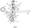
- FIG. 3is an exploded view of the inferior facet joint implant and crosslink rod of FIG. 2 ;
- FIG. 4is a partial cross-sectional view of an attachment mechanism of the facet joint implant of FIG. 2 ;
- FIG. 5is a perspective view of a fixation assembly secured to an inferior strut
- FIG. 6is an exploded view of the fixation assembly and inferior strut of FIG. 5 ;
- FIG. 7is a perspective view of a fixation assembly secured to a superior facet joint implant
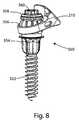
- FIG. 8is a perspective view of an alternate fixation assembly secured to a superior facet joint implant
- FIG. 9is an exploded view of the alternate fixation assembly and superior facet joint implant of FIG. 8 ;
- FIG. 10is a partial cross-sectional view of the alternate fixation assembly and superior facet joint implant of FIG. 8 ;
- FIG. 11is a perspective view of a portion of a spine with an alternate bi-lateral facet joint replacement system implanted into two adjacent vertebrae;
- FIG. 12is a perspective view of an inferior facet joint implant coupled to a crosslink rod
- FIG. 13is an exploded view of the inferior facet joint implant and crosslink rod of FIG. 12 ;
- FIG. 14is a partial cross-sectional view of the inferior facet joint implant of FIG. 12 ;
- FIG. 15is a perspective view of a fixation assembly and an inferior strut
- FIG. 16is an exploded view of the fixation assembly and inferior strut of FIG. 15 ;
- FIG. 17is a perspective view of an inferior implant body coupled to a clip
- FIG. 18Ais a perspective view of an alternate inferior strut
- FIG. 18Bis a perspective view from an alternate angle of the strut of FIG. 18A ;
- FIG. 19is a perspective view of the clip of FIG. 17 and a plug
- FIG. 21is a perspective view of the inferior and superior facet joint implants of FIG. 20 joined by the clip of FIG. 17 ;
- FIG. 22is a perspective view of a multi-level facet joint replacement system implanted in a portion of a spine
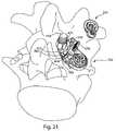
- FIG. 23is a lateral perspective view of a portion of the multi-level facet joint replacement system of FIG. 22 ;
- FIG. 24is a perspective view of a fixation assembly of FIG. 22 ;
- FIG. 25is a perspective view of an inferior facet joint implant of FIG. 22 ;
- FIG. 26Ais a perspective view of a superior facet joint implant of FIG. 22 ; and FIG. 26B is a perspective view of an alternate embodiment superior facet joint implant of FIG. 22 ;
- FIG. 27Ais a lateral view of a fixation assembly base member
- FIG. 27Bis a posterior view of the fixation assembly base member of FIG. 27A
- FIG. 27Cis an anterior perspective view of the fixation assembly base member of FIG. 27A
- FIG. 27Dis a cross-sectional view of the fixation assembly base member of FIG. 27A ;
- FIG. 28Ais a lateral perspective view of an alternate fixation assembly base member; and FIG. 28B is a cross-sectional view of the fixation assembly base member of FIG. 28A ;
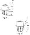
- FIG. 29is a lateral perspective view of an alternate fixation assembly base member
- FIG. 30is a lateral perspective view of an alternate fixation assembly base member
- FIG. 31is a lateral perspective view of an alternate fixation assembly base member
- FIG. 33is a lateral perspective view of an alternate fixation assembly base member
- FIG. 34is a lateral perspective view of an alternate fixation assembly base member
- FIG. 35is a posterior perspective view of a bi-lateral low-profile facet joint replacement system implanted into two adjacent vertebrae;
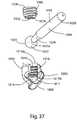
- FIG. 36Ais a perspective view of the low profile inferior facet implant of FIG. 35 ; and FIG. 36B is an alternate perspective view of the low profile inferior facet implant of FIG. 35 ;
- FIG. 37is an exploded view of the low profile inferior facet implant of FIG. 35 ;
- FIG. 38is a perspective view of a fixation assembly of FIG. 35 ;
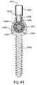
- FIG. 39is a perspective view of another fixation assembly of FIG. 35 ;
- FIG. 40is an exploded view of the fixation assembly of FIG. 39 ;
- FIG. 41is a cross-sectional view of the fixation assembly of FIG. 39 ;
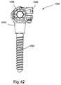
- FIG. 42is a perspective view of an alternate fixation assembly
- FIG. 43is an exploded view of the alternate fixation assembly of FIG. 42 ;
- FIG. 44is a partially exploded perspective view of superior and inferior facet joint implants coupled to the clip of FIG. 17 ;
- FIG. 45Ais a perspective view of an alternate embodiment of a clip
- FIG. 45Bis a perspective view of the clip of 45 A coupled to an inferior facet joint implant
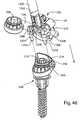
- FIG. 46is a perspective view of the clip and implant of FIG. 45 coupled to a delivery tool, and a superior facet joint implant;
- FIG. 47is a perspective view of the clip and implant of FIG. 45 coupled to a flexing tool, coupled to a superior facet joint implant;
- FIG. 48is a perspective posterior view of a bi-lateral facet joint replacement system with medial-lateral adjustability implant in a portion of a spine;
- FIG. 49is a caudal perspective view of a portion of the system of FIG. 48 ;
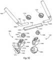
- FIG. 50is an exploded perspective view of a portion of the system of FIG. 48 ;
- FIG. 51is a caudal partial cross-sectional view of a portion of the system of FIG. 48 .
- the present inventionadvances the state of the art by providing systems and methods that can be used to replace natural vertebral facet joints with implantable artificial facet joint prostheses in a manner that provides a high degree of implant adjustability, simplicity, and ease of use.
- polyaxial rotationis rotation that can occur about at least two axes that are not parallel to each other.
- Lock-out or “lock-down” between two or more component partsrefers to a state in which movement of any component part is prevented by frictional, compression, expansion, or other forces.
- a “taper-lock connector”refers to a locking mechanism that uses a taper to effect locking.
- a perspective viewdepicts a portion of a spine including a first vertebra 2 and a second vertebra 4 .
- a system 10 of bi-lateral facet joint replacements joined by a crosslink rod passing through a spinous process 6is implanted in the vertebrae.
- an inferior facet joint implant 100is secured to a fixation assembly 300 implanted in vertebra 4 .
- fixation assembly 300implanted in vertebra 4 .
- fixation assembly 300implanted in vertebra 4
- fixation assembly 300implanted in vertebra 4
- a superior facet joint implant 200is secured to a fixation assembly 300 implanted in vertebra 2 , and together the superior facet joint implant 200 and fixation assembly 300 form superior facet joint prosthesis 12 .
- an inferior facet joint implant 101is secured to a fixation assembly 300 implanted in vertebra 4
- a superior facet joint implant 201is secured to a fixation assembly 200 implant in vertebra 2 .
- many of the facet joint replacement protheses, implants and fixation assemblies described hereinmay each be configured in a “right” or a “left” configuration to be implanted on the right or left lateral side of the vertebrae. However, in most cases, only one (right or left) configuration will be described, and it is assumed that the other (right or left) configuration is a mirror-image of the one described. It is also appreciated that the implants described herein may be implanted bi-laterally as in FIG. 1 , or unilaterally, if desired.
- FIG. 2a perspective view depicts polyaxially adjustable left inferior facet joint implant 100 .
- Inferior facet joint implant 100comprises an inferior articular body 102 , an inferior strut 104 , and an attachment mechanism 106 which adjustably secures the articular body to the inferior strut.
- the attachment mechanism 106has an adjustable configuration in which the inferior articular body 102 can rotate relative to the inferior strut 104 about three orthogonal axes, and it has a locked configuration in which the inferior articular body 102 is rigidly secured to inferior strut 104 .
- a crosslink rod 108may optionally be secured to the implant 100 by a split clamp 110 .
- the attachment mechanism 106may be actuated to simultaneously lock the crosslink rod 108 in the split clamp 110 as the inferior articular body 102 is locked to the inferior strut 104 .
- a clamp axis 111extends longitudinally through the attachment mechanism.
- a strut axis 105extends longitudinally along the inferior strut 104 .
- the chamfered openingsmay provide additional range of motion between the inferior articular body and the inferior strut 104 as the articular body 102 is polyaxially adjusted prior to locking down.
- An inferior articular surface 122is located on the exterior of the inferior articular body 102 , and is shaped to replace a natural inferior articular surface of a vertebra.
- Inferior facet implant 100may be implanted in conjunction with a superior facet implant, wherein the inferior articular surface 122 articulates with an artificial superior facet articular surface.
- inferior facet implant 100may be implanted such that the inferior articular surface 122 articulates with a natural superior facet articular surface. In either case, the articulation between superior and inferior articular surfaces, whether natural or artificial, provides preservation of a level of natural spinal motion.
- the split shell 128has a circular neck portion 132 through which passes a bore 134 .
- the bore openingis surrounded by a radial spline 136 .
- Adjacent to the neck portion 132is a spherical portion 138 which comprises two expandable lobes 140 , 142 .
- An interior surface 143 of the lobes 140may be tapered.
- the present embodiment of the inventionincludes two lobes, however it is appreciated that more lobes may be included, or other expandable portions, in other embodiments.
- the split shell 128fits over the conical expander 126 such that a threaded post 146 of the conical expander passes through the bore 134 .
- An expansion portion 148 of the conical expander 126is forked and has two opposing flanges 150 , 152 which are shaped to fit around and grip the inferior strut 104 .
- An inner wall 153 of the flangesis curved to fit around the inferior strut, and the outer walls 154 , 156 are tapered.
- the split ring clamp 110comprises an inner ring 160 , an outer ring 162 and a collar 164 which joins the inner and outer rings.
- the collar 164is shaped to receive and grip the crosslink rod 108 .
- the split ring clampis configured such that when the inner and outer rings 160 , 162 are compressed together, a diameter of the collar 164 decreases and the collar can tighten around and secure the crosslink rod.
- the surface of an exterior side of the inner ring 160is a radial spline 166 , which is shaped to engage with the radial spline 136 on the split shell 128 .
- the split shell 128When assembled, the split shell 128 fits over the conical expander 126 , and the two parts fit within the inferior articular body 102 such that the interior cavity 112 houses the expansion portion 148 of the conical expander 126 nested inside the spherical portion 138 of the split shell 128 .
- the conical expander 126 , split shell 128 and inferior articular body 102are oriented so that in general the flanges 150 , 152 are adjacent to the lobes 140 , 142 , and the lobes are adjacent to the interior wall 114 of the interior cavity 112 .
- a rod portion of the inferior strut 104fits between the flanges 150 , 152 of the conical expander.
- the split ring clamp 110fits over the threaded post 146 of the conical expander so that the radial spline 166 of the split clamp meets the radial spline 136 of the split shell 128 .
- the crosslink rod 108extends through the collar 164 of the split clamp.
- the nut 130is threaded onto the threaded post 146 of the conical expander.
- the implantis adjustable in multiple ways.
- the crosslink rod 108has relative angular freedom of motion about the clamp axis 111 and the inferior strut axis 105 .
- the position of the crosslink rod 108 relative to the split clamp 110may be adjusted such that a relatively longer or shorter portion of the crosslink rod 108 extends through the clamp. This provides an opportunity to select the best fit to the patient's anatomy and the specific vertebral level being treated.
- the position of the inferior strut 104may be adjusted relative to the inferior articular body 102 such that a relatively longer or shorter length of the inferior strut 104 extends through the flanges 150 , 152 of the conical expander 126 .
- the inferior strut 104has relative angular freedom of motion about the clamp axis 111 .
- the inferior articular body 102may be polyaxially rotated about the conical expander 126 and the split shell 128 .
- the adjustmentsprovide relative rotation between the inferior articulation surface 122 and the inferior strut 104 about three orthogonal axes.
- relative translation between the inferior strut 104 , the inferior articulation surface 122 , and the crosslink 108is permitted.
- the attachment mechanism 106is locked down in a taper lock mechanism by actuating, or turning the nut 130 .
- the conical expander 126is urged “upward” through the nut 130
- the outer ring 162 of the split clamp 110is urged “downward” toward the inner ring 160 .
- the conical expander 126moves, the flanges 150 , 152 push against the lobes 140 , 142 of the split shell 128 , and in turn the lobes expand and push against the interior wall 114 of the interior cavity 112 . Simultaneously, the flanges 150 , 152 are compressed around the inferior strut 104 .
- the collar 164 of the split clamp 110is compressed around the crosslink rod 108 as the inner 160 and outer 162 rings of the clamp are urged together.
- the nut 130may be actuated until the resulting internal compression prevents any further motion, and the mechanism is locked down.
- the inferior implant 100may be delivered in an assembled, but not locked down, configuration.
- the crosslink rod 108may be included in the assembly, provided separately, or excluded.
- the inferior implant 100may be delivered in combination with a superior implant, in which a clip or other temporary fastener holds the inferior articular surface to a superior articular surface of the superior implant.
- the ring 180may be set at an angle relative to the central portion 180 and the strut post 184 .
- the strut post 184may be at an angle relative to the central portion and the ring; also the central portion 180 may be straight, bent or curved.
- FIG. 6is an exploded view of the inferior strut 104 and the fixation assembly 300 .
- the fixation member 302which may be a pedicle screw, has a distal threaded bone-engaging portion 310 , a shaft 312 , and a proximal threaded attachment portion 314 .
- the base member 304is cannulated throughout, and has a bone-engaging portion 316 , a flange 318 and a tapered portion 320 .
- the bone-engaging portionmay be tapered to provide compression to the surrounding bone, and may have a plurality of fins 317 which prevent rotation of the base 304 in the bone.
- the bone-engaging portion 316may include teeth, studs, posts, fins, or combinations thereof, or other anti-rotation features, or no anti-rotation features.
- the tapered portion 320may serve as an attachment portion, configured for attachment of an implant.
- a tool engagement rim 322includes a plurality of notches 324 .
- Other embodiments of the basemay include threads or other features instead of notches configured to engage a tool.
- the split sphere 306is sized to fit over the tapered portion 320 of the base 304 , and includes a plurality of slits 328 which allow the sphere to be expandable.
- the split sphere 306may also include a tapered inner wall.
- the top nut 308has a threaded bore 332 and a flange 334 which encircles the nut 308 .
- the ring 182may be polyaxially adjusted around the split sphere so that the inferior strut 104 attains a desired orientation.
- a compression lockout tool(not shown) engages the notches 324 of the tool engagement rim 322 on the base 304 .
- Other embodiments of the basemay include a threaded tool engagement interface, configured to engage with a threaded lockout tool.
- the lockout toolprovides compression on the split sphere 306 , urging it farther onto the tapered portion 320 toward the flange 318 . As the split sphere 306 moves down the tapered portion 320 , it expands and engages the ring 182 of the inferior strut 104 .
- the toolis removed.
- the top nutis threaded onto the threaded attachment portion 314 of the fixation member 302 , to retain the base 304 , sphere 306 and ring 182 on the fixation member, and to further secure the bone-engaging portion 316 in the vertebra.
- the base 304 , split sphere 306 , and ring 182may be assembled and locked out independently of the fixation member 302 , then dropped onto the fixation member 302 and retained with the top nut 308 .
- the inferior implant 100may be secured to the inferior strut 104 before or after the inferior strut 104 is locked into position with the base 304 and split sphere 306 .
- the superior implant 200is shown secured to the fixation assembly 300 .
- the superior implant 200may be monolithic and includes a superior articulation surface 202 shaped to replace a natural superior articular surface of a vertebra, a fixation portion or ring 204 , and may include at least one notch-like gripping feature 206 .
- the superior implant 200may be secured to the fixation assembly 300 in the same method as described previously for the inferior strut 104 .
- the ring 204 of the superior implant 200is locked in position relative to the split sphere 306 and the base member 304 .
- the base 304 , split sphere 306 and implant 200may be dropped over an implanted fixation member 302 , and the top nut 308 secured on the fixation member to retain the assembly.
- the superior implant 200may be delivered in combination with an inferior implant 100 , and the superior articular surface 202 may be temporarily clipped to the inferior articular surface 122 .
- the components comprising the fixation assembly 300 , superior 200 , 201 and inferior 100 , 101 implants and crosslink 108may be implanted as follows.
- the pediclesare prepared for implantation, which may include removal of natural facet surfaces and bone preparation, and may include a broaching step to shape the pedicles to receive the base components. Broaching may ensure bone ingrowth and better mechanical retention of the bases and therefore the full implant system.
- the fixation member 302 for each fixation assembly 300is driven into the pedicles to a prescribed or desired depth.
- a base member 304is placed on each fixation assembly 300 , and the bone-engaging portion may be urged into the bone by pressing, tapping or other means.
- a split sphere 306is placed on the bases in the caudal vertebra 2 intended for the superior implants, and the fixation portions of the superior implants 200 , 201 are placed over the split spheres, and locked down relative to the fixation assembly as described previously.
- the split sphere 306may be captured in the ring 204 of the implant 200 or 201 , and the implant/ring assembly placed on the base 304 .
- the inferior implants 100 , 101are each assembled with an inferior strut 104 , but not yet locked to the strut.
- a split sphere 306is captured in the fixation ring 182 of each strut 104 , and each inferior implant/strut/sphere assembly is placed on the attachment portion of the base member 304 on a fixation member 302 on the cephalad vertebra 4 .
- An offset distance between the inferior articular surface and the fixation assemblymay be adjusted by moving the conical expander 126 relative to the inferior strut 104 .
- the inferior articular surfacesare aligned with the superior articular surfaces, and may be temporarily clipped together to maintain the alignment.
- the orientation of the inferior articular surface 122may be polyaxially adjusted relative to the strut 104 by moving the split shell 128 relative to the cavity 112 .
- the inferior implant/strut assembliesare locked down to the fixation assemblies.
- the crosslink 108may now be inserted through the collar 164 of the split clamp 110 of one inferior implant 100 or 101 and optionally through a prepared spinous process, and through the other collar 164 on the remaining inferior implant 100 or 101 . It is appreciated that as the crosslink 108 is inserted, the split clamp 110 is rotatable about the clamp axis 111 . Therefore, the crosslink 108 may be positioned to pass through a spinous process, or may pass through soft tissue caudal to the spinous process. Alternatively, the crosslink 108 may be inserted before the inferior implants are locked down to the fixation assemblies.
- each inferior implant 100 , 101are actuated to lock down the implants, fixing the positions of the articular surfaces 122 , the inferior struts 104 and the crosslink 108 relative to their respective fixation assemblies. Post-operatively, the articular surfaces will be capable to articulate against one another, allowing a level of natural spinal motion.
- the inferior articular body 102may be available packaged with the superior implant 200 , temporarily clipped together such that the articular surfaces 122 , 202 are in a desired alignment.
- the inferior articular body 102is inserted with the superior implant 200 as the superior implant 200 is placed and locked with the fixation assembly 300 .
- the inferior strut 104 and the remaining components of the inferior implant 100including the conical expander, split shell, and split clamp are assembled with the inferior articular body 102 .
- the fixation portion, or ring 182 of the inferior strut 104is assembled and locked down with the inferior fixation assembly 300 .
- the insertion of the crosslink 108 and final lockdownis as described previously, and the clip is removed.
- the inferior implant 100may be available secured to a clip.
- the implant 100with the attached clip, may be inserted adjacent to an already implanted and locked down superior implant, and the inferior and superior implants temporarily clipped together.
- the inferior strutis adjusted and locked down to its fixation assembly.
- the insertion of the crosslink 108 and final lockdown of the inferior implantis as described previously, and the clip is removed.
- System 10may also be implanted on multiple vertebral levels to provide facet joint replacement across several levels.
- additional superior implantscould be added to the fixation assemblies 300 which secure the inferior struts 104 , to extend the system in a cephalad direction.
- additional inferior struts coupled to inferior implantscould be added to the fixation assemblies 300 which secure the original superior implants 200 .
- fusion rods(not shown) may be secured between fixation assemblies 300 on adjacent vertebra to provide rigid fusion at a desired vertebral level.
- FIG. 8presents an alternative embodiment of a polyaxially adjustable fixation assembly 350 with an alternative embodiment of a superior implant 210 .
- FIG. 9presents an exploded view of fixation assembly 350
- FIG. 10presents a cross-sectional post-assembly view of the assembly.
- fixation assembly 350comprises a fixation member 352 , a base member 354 , a flanged split sphere 356 , a capture nut 358 , and a top nut 360 .
- the cannulated base member 354has a bone-engaging portion 362 which may include anti-rotation features such as fins, teeth or studs.
- a tapered portion 364has a threaded lumen 366 .
- the split sphere 356includes a split flange 368 which encircles one open end of the sphere.
- the capture nut 358has a threaded outer surface 370
- the top nut 360has a threaded inner surface 372 .
- Fixation assembly 350may also be termed an attachment mechanism. It is appreciated that fixation assembly 350 may be substituted for fixation assembly 300 in any fixation procedure disclosed or depicted herein, and vice versa. Also, a combination of fixation assemblies 300 and 350 may be used in an implant system.
- the fixation member 352is initially implanted into the pedicle, and the base member 354 is inserted over the fixation member 352 and seated in the bone.
- the split sphereis placed over the tapered portion 364 of the base member 354 .
- a fixation portion, or ring 212 of the superior implant 210is placed around the split sphere 356 .
- the ring 212may be polyaxially adjusted to attain a desired orientation of the superior implant 210 .
- a lockout tool(not shown) is actuated to effect the taper lock.
- the lockout toolhas an externally threaded inner shaft tip which is engaged in the threaded lumen 366 of the base member 354 .
- the lockout toolis actuated, using tensile force to simultaneously pull on the base member 354 with the inner shaft, and push on the flange 368 of the split sphere 356 with an outer shaft. This force moves the split sphere 356 farther onto the tapered portion 364 .
- the split sphere 356expands and engages the ring 212 of the superior implant 210 until all motion ceases and the position of the ring 212 is locked down.
- the lockout toolis unthreaded and removed, and the capture nut 358 is threaded into the tapered lumen 366 , also capturing the flange 368 of the split sphere 356 .
- the capture nut 358is included to ensure the long-term integrity of the lock.
- the top nut 360is threaded onto the fixation member 352 , and assists in holding the tapered base 362 against the bone surface.
- the top nut 360 and capture nut 358may use the same driver.
- a perspective posterior viewdepicts an alternative embodiment of a bi-lateral facet joint replacement system 20 , implanted in two vertebrae.
- superior facet joint prosthesis 22comprises a superior implant 210 and a fixation assembly 300 , secured to the first vertebra 2 .
- the superior articular surfacearticulates with an inferior articular surface of an inferior facet joint prosthesis 21 , which comprises implant 400 and fixation assembly 500 .
- An polyaxially adjustable attachment mechanismcouples an inferior implant body to one end of an inferior strut 404 , and a crosslink rod 109 which crosses a sagittal plane of the vertebrae.
- An opposite end of the inferior strutis secured to the second vertebra 4 by the fixation assembly 500 .
- a mirror-image of the systemis implanted, including superior implant 211 , second fixation assembly 300 , inferior implant 401 , inferior strut 405 and fixation assembly 501 .
- the crosslink rod 109links the left inferior implant 400 to the right inferior implant 401 .
- only one lateral side of the systemwill be depicted and described.
- FIG. 12depicts the inferior implant 400 , which comprises an inferior articular body 402 , an inferior strut 404 , and an attachment mechanism 406 which polyaxially adjustably secures the articular body to the inferior strut.
- the crosslink rod 109may be also secured to the inferior implant 400 by the attachment mechanism 406 .
- Attachment mechanism 406may have two configurations: an adjustable configuration in which there is relative rotation between the inferior articular body 402 , the inferior strut 404 and the crosslink rod 109 , and a locked configuration in which the inferior articular body 402 , the inferior strut 404 and the crosslink rod 109 are rigidly secured to each other.
- FIG. 13is an exploded view of the inferior articular body 402 , inferior strut 404 , crosslink rod 109 and the attachment mechanism 406 .
- the inferior articular body 402is monolithic and comprises an inferior articulation surface 403 shaped to replace a natural inferior articular surface of a vertebra, and a connection feature which has a rounded surface 408 , which in this embodiment is a spherical surface.
- a compressible member 410includes a conical portion 412 and a threaded post 414 .
- the conical portion 412has an interior cavity 416 encircled by a plurality of expandable fingers 418 .
- the interior cavity 416is shaped to receive the rounded surface 408 .
- the inferior strut 404has a first end 420 which is shaped as a rod and serves as the fixation portion for the strut.
- Other embodiments of the inferior strutmay have a first end shaped as a ring or another shape.
- a second end 422is shaped as a ring, and comprises a split ring clamp 424 , the split ring clamp having an inner ring 426 , an outer ring 428 , and a collar 430 , which connects the inner and outer rings.
- the collar 430is oriented generally orthogonal to the inner and outer rings.
- the collar 430is shaped to receive a split sphere 432 , which has an interior shaped to receive the crosslink rod 109 .
- a nut 440is configured to be threaded on the threaded post 414 .
- Inferior strut 404may be straight, or it may be curved or bent such that the first and second ends 420 , 422 are oriented at an angle relative to one another, as seen in FIG. 11 .
- FIG. 14is a partial cross-sectional view of the attachment mechanism 406 components in the locked configuration (the collar 430 , split sphere 432 and crosslink 109 are not visible in this figure).
- a clamp axis 411extends longitudinally through the attachment mechanism.
- the rounded surface 408is received in the cavity 416 of the compressible member 410 .
- the split ring clamp 424fits around the compressible member 410 , with the inner ring 426 around the conical portion 412 and the outer ring 428 around the threaded post 414 .
- the collar 430fits around the split sphere 432 , which receives the crosslink rod 109 .
- the attachment mechanism 406is adjustable in multiple ways.
- the inferior articular surface 403may be polyaxially rotated relative to the inferior strut 404 and the crosslink rod 409 by rotation of the rounded surface 408 .
- the split sphere encompassing the crosslink rod 109may be polyaxially rotated within the split ring clamp 424 relative to the inferior strut 404 and the inferior articular surface 403 .
- a length of the crosslink rod 109 which extends through the attachment mechanism 406may be adjusted.
- the inferior strut 404has relative angular freedom of motion about the clamp axis 411 . These adjustments provide relative rotation between the inferior articulation surface 403 and the inferior strut 404 about three orthogonal axes.
- An attachment mechanism 407for the right side of the vertebrae, is configured as a mirror image of attachment mechanism 406 .
- the attachment mechanism 406is locked down by actuating, or turning the nut 440 .
- Lockdown of the attachment mechanismlocks out both the position of the inferior strut relative to the inferior articulation surface, and the position of the crosslink.
- the compressible member 410is urged “upward” through the nut 440 , while the outer ring 428 of the split ring clamp 424 is urged “downward” toward the inner ring 426 .
- the compressible member 410moves, the tapered outer wall of the conical portion 412 engages the inner surface of the inner ring 426 .
- the interior wall of the conical portion 412exerts compressive force against the rounded surface 408 in the interior cavity 416 .
- the collar 430 of the split ring clamp 424is compressed around the split sphere 432 , which compresses around the crosslink rod 109 , as the inner 426 and outer 428 rings of the clamp are urged together.
- the nut 440may be actuated until the resulting internal compression prevents any further motion, and the mechanism is locked down.
- FIG. 15is a perspective view of the fixation assembly 500 , coupled to inferior strut 404 .
- Fixation assembly 500comprises a fixation member 502 , a base member 504 , a top nut 506 , a split ring clamp 508 , a split sphere 510 and a set screw 512 .
- Fixation assembly 500may also be termed an attachment mechanism, and it is adjustable, permitting polyaxial rotation of the inferior strut relative to the fixation member 502 .
- FIG. 16is an exploded perspective view of the fixation assembly 500 and the inferior strut 404 .
- the fixation member 502comprises a threaded bone-engaging portion 514 and a threaded attachment portion 516 .
- the base member 504comprises a receptacle 518 with a fixation bore 520 sized to receive the fixation member 502 , and a bone-facing side 519 .
- On the bone-facing side 519may be fins, pegs, teeth or other anti-rotation features.
- the base member 504may be dish-shaped as in FIG. 16 , or may be spherical, tapered, or another shape.
- Coupled to the receptacle 518is a tapered pedestal 521 which encircles a threaded attachment bore 522 sized to receive the set screw 512 .
- the top nut 506is sized to fit into the receptacle 518 , and to be threaded onto the attachment portion 516 of the fixation member.
- the split ring clamp 508comprises an inner ring 526 , an outer ring 528 , and a collar 530 which connects the inner and outer rings.
- An inner wall 527 of the inner ring 526may be tapered.
- the set screw 512is threaded and sized to be received in the attachment bore 522 .
- the split sphere 510is sized to fit around the rod-like fixation portion or first end 420 of the inferior strut 404 , and sized to fit inside the collar 530 of the split ring clamp 508 .
- a mirror-image fixation assembly 501is configured to be implanted on the right side of the vertebra.
- fixation assembly 500may be assembled and locked down as follows.
- Fixation member 502is driven into a prepared pedicle at a desired depth.
- Base member 504is placed on the fixation member 502 so that the threaded attachment portion 516 fits through the fixation bore 520 .
- the outer surface of the base member 504may rest on the prepared pedicle.
- the top nutis threaded onto the attachment portion 516 and actuated to secure the base 504 to the pedicle.
- the split sphere 510is captured in the collar 530 of the split ring clamp 508 , and the fixation portion or rod portion 420 of the inferior strut may be slid into the split sphere.
- the split ring clamp 508now connected to the inferior strut 404 , is placed on the pedestal 521 so that the inner ring 526 surrounds the tapered pedestal 521 .
- the set screw 512is fit through the outer and inner rings 526 , 528 and threaded into the attachment bore 522 .
- the angle of the inferior strut 404 relative to a clamp axis 532which may be parallel to the fixation member 502 , may be adjusted.
- the split sphere 510may be polyaxially rotated within the collar 530 , permitting polyaxial adjustment of the inferior strut 404 .
- the fixation assembly 500is locked down by actuating the set screw 512 .
- set screw 512As set screw 512 is tightened, outer ring 528 is urged toward inner ring 526 . As the rings 526 , 528 come together, collar 530 is compressed around split sphere 510 , which in turn compresses around rod portion 420 , locking its position.
- set screw 512As set screw 512 is turned, the tapered inner wall 527 of inner ring 526 is rigidly secured against the tapered pedestal 521 , fixing the position of the split clamp ring 508 relative to the clamp axis 532 .
- the components comprising the fixation assemblies 300 , 500 , 501 , superior 210 , 211 and inferior 400 , 401 implants and crosslink 109may be implanted as follows.
- the pediclesare prepared for implantation, which may include resection of natural facet surfaces and bone preparation, and may include a broaching step to shape the pedicles to receive the base components. Broaching may ensure bone ingrowth and better mechanical retention of the bases and therefore the full implant system.
- the fixation member 302 for each fixation assembly 300is driven into the pedicles of the caudal vertebra 2 to a prescribed or desired depth.
- a tapered base 304is placed on each fixation member 302 .
- a split sphere 306 and superior implant 210 , 211is placed on the tapered bases 304 intended for the superior implants, and the taper lock is locked down relative to the fixation assembly as described previously with reference to FIGS. 8-10 .
- the fixation members 502 for the fixation assemblies 500 , 501are driven to a desired depth in the cephalad vertebra 4 .
- base member 504is placed over the fixation member 502 and secured by the top nut 506 .
- the inferior strut 404is assembled with the inferior articular body 402 , and the attachment mechanism 406 as set forth previously, but not locked down.
- the split ring clamp 508is assembled with the split sphere 510 , and together they are slid onto the fixation portion of inferior strut 404 .
- the split ring clamp 508now attached to the inferior strut 404 and the inferior implant 400 , is placed on the tapered pedestal 521 of the base member 504 .
- the inferior implants 400 , 401are positioned so that the inferior articular surfaces are aligned with the superior articular surfaces of the superior implants 210 , 211 , and the inferior and superior articular bodies on each side may be temporarily clipped together to maintain the alignment.
- the inferior implant/strut assembliesare locked down to the fixation assemblies by actuating the set screws 512 .
- the crosslink 109may now be inserted through the collar 530 of the split clamp 508 of one inferior implant 400 or 401 and through a prepared spinous process, and through the other collar 530 on the remaining inferior implant 400 or 401 .
- the crosslink 109may be inserted before the inferior implants are locked down to the fixation assemblies.
- the attachment mechanisms 406 of each inferior implant 400 , 401are actuated to lock down the implants, fixing the positions of the articular surfaces 403 , the inferior struts 404 and the crosslink 109 .
- an inferior articular body 470may be available pre-packaged temporarily locked to a coupler, or clip 550 with a plug 570 , which will be described in further detail below.
- a gripping tool(not shown) may be used to hold the inferior articular body 470 .
- the attachment mechanism 406 and the inferior strut 404(not seen) are assembled to the inferior articular body 470 .
- the superior implant 210is placed on and taper locked with the fixation assembly 300 , which is implanted in the pedicle.
- FIGS. 18A and 18Bdepict different perspective views of an alternate inferior strut 450 .
- Inferior strutcomprises a first end 452 and a second end 454 .
- Fixation portion or first end 452is post-like, and may be configured to be secured by a fixation assembly such as fixation assembly 500 seen in FIG. 15 .
- Other embodiments of the strutmay include a first end which is a ring or a different shape.
- the second end 454comprises a split ring clamp 456 , which includes an inner ring 458 and an outer ring 460 , which are joined by a collar portion 462 . As seen in FIGS.
- the collar portionmay be substantially orthogonal relative to the rings 458 , 460 , or it may be at another angle. Additionally, the angle of the second end 454 relative to the first end 452 may vary.
- Inferior strut 450may be secured to an articular body by an attachment mechanism in the same manner as described for inferior strut 404 ; that is, a single actuating member may be actuated to urge the inner and outer rings 458 , 460 together and compress the collar 462 .
- Another alternative inferior strutmay include separate polyaxially adjustable attachment mechanisms for a crosslink and an inferior articular body.
- Such an alternative strutmay include a first ring positioned and shaped to receive a polyaxially adjustable crosslink rod, while a second ring is positioned and shaped to receive a polyaxially adjustable connection to an inferior articular body.
- Each ringmay have an independent lockout mechanism such as a nut or screw.
- the plug 570comprises a handle 571 and two wires 572 which are sized to extend through the bores 560 of the inferior posts 558 of the clip 550 .
- the wires 572urge apart the flexible split ends 562 from a narrow first configuration to an expanded second configuration in which the slots 564 are widened, and the flanges 566 on each post are farther apart.
- the split ends 562deform, moving toward one another from the expanded second configuration to the narrow first configuration.
- the inferior articular body 470is shown coupled with the clip 550 and the plug 570 .
- the inferior posts 558extend through tubes 472 formed on the inferior implant 470 , such that the split ends 562 and flanges 566 emerge outside of the tubes.
- the plug 570is fully inserted through the clip bores 560 , and therefore the wires 574 keep the split ends in the expanded second configuration.
- the widened flanges 566cause the diameter of the split ends 562 to be greater than the diameter of the tubes 472 , retaining the articular body 470 and preventing the clip 570 from being withdrawn from the inferior articular body 470 .
- the inferior articular body 470with or without other attached components such as a compressible member and/or an inferior strut, may be clipped to a superior implant.
- a perspective viewshows the inferior articular body 470 joined to the compressible member 410 , attached to a clip 550 .
- a direction arrow 580indicates the direction in which the articular body, compressible member and clip may be moved to align them with a superior implant 211 .
- the superior implant 211is implanted in a pedicle via fixation assembly 350 previous to alignment with the inferior articular body 470 , and a fixation assembly 500 is implanted into the adjacent pedicle.
- the clipmay be moved until the superior posts 556 fit into openings 582 on the superior implant 211 .
- clip 550 and inferior articular body 470may be joined with strut 450 and with superior implant 211 into an assembly, and the assembly moved on to fixation members implanted in the pedicles.
- a multi-level facet joint replacement system 30is shown implanted in a portion of a spine. Between adjacent vertebrae 8 and 4 , a first artificial facet joint replacement assembly replaces the natural facet joints. The first assembly is linked to a second artificial facet joint replacement assembly which replaces the natural facet joints between adjacent vertebrae 4 and 2 . At the next level, the second artificial facet joint replacement assembly is linked to a fusion rod system which provides rigid fusion between vertebra 2 and the sacrum 1 . Crosslink rods connect the left lateral assemblies with the right lateral assemblies.
- a lateral viewshows the left lateral side of system 30 .
- Systemcomprises many of the same components as system 20 .
- system 30includes a fixation assembly 600 configured to be implanted in a first vertebra.
- a fixation portion of inferior strut 450is secured by a split clamp to fixation assembly 600 , and forms part of inferior facet implant 700 .
- Inferior facet implant 700articulates with a first superior facet implant 800 which is secured to a first fixation assembly 300 which is configured to be implanted a second vertebra.
- An inferior strut 404is secured by a split clamp to the first superior facet implant 800 , and forms part of inferior facet implant 400 .
- Multi-level applications of this systemare not restricted to three or four levels; additional vertebral levels could be included by adding additional components including inferior implants, superior implants, crosslinks, and/or fusion rods. It is appreciated that the sizes and configurations of components included in system 30 may vary to fit various vertebral sizes, offset distances and configurations and particular patient anatomy. System 30 is polyaxially adjustable at each vertebral level.
- Fixation assembly 600comprises fixation member 602 , base member 604 with tapered pedestal 605 , top nut 606 , split ring clamp 608 , split sphere 610 and set screw 612 .
- Fixation assembly 600is similar to fixation assembly 500 seen in FIGS. 16 and 17 , and is assembled similarly.
- Base member 604may be rotated about the axis of fixation member 602 prior to lockdown by top nut 606 .
- split ring clamp 608may be rotated about the axis of the tapered pedestal 605 prior to lockdown by set screw 612 .
- Base member 604may extend farther along the fixation member and deeper into the bone than base member 504 , and may include anti-rotation elements such as teeth, fins, and posts or studs, among others. It is appreciated that various component parts of the fixation assemblies herein disclosed may be mixed and matched to form a variety of other alternatives. For example, base members 504 and 604 may be substituted for one another if appropriate for the application, as may set screws 512 and 612 . Similarly, fixation assembly 500 may be coupled with inferior strut 450 , or another inferior strut or fusion rod, and fixation assembly 600 may coupled with inferior strut 404 , or another inferior strut or fusion rod.
- Superior implant 800comprises a superior articulating surface 802 and a fixation portion, or ring 804 .
- Superior articulating surface 802may be shaped to articulate with an inferior facet articulating surface. It is appreciated that the dimensions of the surface 802 may vary, as can the orientation and angle of the surface 802 relative to the remainder of the implant.
- the ring 804is shaped to receive a split sphere such as sphere 306 or 356 , thus allowing polyaxially adjustable coupling of the implant 800 to a fixation assembly such as fixation assembly 300 .
- superior facet implant 810may be similar to implant 800 .
- Implant 810comprises a superior articulating surface, a fixation portion or ring 814 , a pedestal 816 and a bore 818 .
- the implantfurther comprises at least one notch 820 configured to receive a tool.
- Either superior implant 800 or 810may include features to allow the implant to be held in alignment with an inferior implant by a clip or gripping tool.
- FIGS. 27-34depict alternative embodiments of facet implant base members.
- Each base membercomprises a tapered portion shaped to mate with an expandable member, or collet that is tapered inside and substantially spherical outside, such as split sphere 306 , 356 or split shell 128 .
- the tapered surfacefacilitates a taper lock between the base and the collet (and inferior or superior implant), thereby locking out adjustability between the implant and the base as described previous with regard to FIGS. 6 and 9 .
- Below the tapered portionmay be a flange to prevent subsidence and provide a stable surface against the adjacent bone, and to provide additional surface area for bone ingrowth.
- a generally cylindrical bone-engaging portion of the baseextends down into the pedicle of the vertebra.
- the bone-engaging portionwhich may also be tapered forming a conical shape, may have any number of fins or other features (3-7 in preferred embodiments) which may project into the surrounding bone to resist rotation forces.
- Each basehas a lumen extending throughout both the tapered portion and bone-engaging portion to fit over a pedicle screw or other fixation member.
- the lumenmay be cylindrical or may include a non-cylindrical indexing surface with one or more flat sections, shaped to receive a hexagonal driver or a driver of another shape, including triangular, square, pentagonal, or octagonal, among others.
- each basemay have engagement features such as notches or threads which allow a tool or gripping instrument to engage with and hold the base during implantation and lockout procedures. Implantation of each base may follow the same procedures as set forth previously for base 304 . Bases with fins or other protruding anti-rotation features may require additional bone preparation steps such as broaching to create slots in the bone for the fins.
- Each base member embodimentmay differ in the number of fins that radiate outward from the center axis to resist rotation.
- the length, width and taper of fins or other anti-rotation featuresmay vary.
- Other embodimentscould use studs, pegs or posts instead of fins, or have slots in the bone-engaging portion that extend downward into the pedicle.
- the flange and/or bone-engaging portionmay be coated with bone in-growth material such as porous material or hydroxyapatite, among others.
- Additional embodimentsmay incorporate sawteeth to allow for self-guiding and/or self-cutting, therefore eliminating a separate preparation step. It is appreciated that the bases disclosed herein may be used with the fixation assemblies also disclosed herein, or in other orthopedic applications employing bone-engaging fixation members for which the anti-rotation or other properties of the bases are desired.
- a base membersuch as those disclosed herein with a fixation member such as a pedicle screw may provide several advantages to a pedicle screw alone.
- the contact area between the pedicle and the fixation assembly over which bending loads are distributedwill be increased, since the bone-engaging portion of each base provides a greater surface to bone contact area than a pedicle screw alone.
- a bone in a healthy person or animalwill adapt to the loads it is placed under. If loading on a particular bone increases, the bone will remodel itself over time to become stronger to resist that sort of loading.
- Increasing the bone contact area through the use of a base membermay therefore result in strengthening of a larger portion of the bone around the implant fixation assembly. Additionally, less load may be placed on the pedicle screw, which may result in decreased likelihood of loosening of the screw over time.
- five evenly spaced fins 862project outward from the bone-engaging portion 856 .
- the fins 862may prevent rotation of the base 850 in the pedicle.
- a fillet 864is located between each fin and the adjacent fin and provides a transition between the flange 854 and the bone-engaging portion 856 .
- there may be fewer or more finsand the fins may be evenly or unevenly spaced, or paired, or grouped.
- the morphology of the finsmay vary; some fins may have sharp, well-defined edges while others may have more rounded edges.
- the finsmay taper between the flange and the distal end of the bone-engaging portion.
- the sizes of the fillets 864may vary; a larger fillet will provide a less sharp, more continuous transition between fins. Providing more gradual, less acute transitions between features on the base may prevent the occurrence of low-load areas where less bone in-growth might occur.
- the curved sections 875have a diameter outside the dimensions of the flat sections, allowing rotary bone preparation tools to be passed through and used in the lumen.
- the tapered portionincludes threads 877 which may extend throughout the tapered portion as shown or, in other embodiments, may extend only partially through the tapered portion.
- the threads 877are configured to engage with a placement and/or lockout tool, which may provide force to effect a taper lock between an implant and the base, as set forth previously.
- Implant base 880has a tapered portion 882 , a flange 884 and a bone-engaging portion 886 .
- a plurality of fins 888extend outward from the bone-engaging portion 886 .
- Each fin 888is serrated with several teeth 889 , which may provide self-broaching of the bone during implantation of the base.
- Implant base 890has a tapered portion 892 , a flange 894 and a bone-engaging portion 896 .
- a plurality of jagged fins 898extend outward from the bone-engaging portion 896 .
- Each fin 898comprises a series of teeth 899 which may be graduated in size. Similar to implant base 880 , the teeth may provide self-broaching during implantation, and may reduce the bone preparation needed prior to implantation.
- Implant base 910comprises a tapered portion 912 and a bone-engaging portion 914 .
- the dish-shaped bone-engaging portion 914has a greater diameter than the tapered portion 912 .
- Bone-engaging portion 914has a spherical bone-contacting surface 915 .
- the configuration of the bone-engaging portion 914may prevent subsidence of the implant, distribute the implant load over a larger surface area, and provide increased surface area for bone ingrowth.
- a plurality of pegs 916protrude from the bone-engaging portion 914 and may prevent rotation of the base. The pegs 916 are positioned farther away from the central axis of the base 910 , in comparison to the configuration of base 900 and pegs 908 .
- Implant base 920comprises a tapered portion 922 , a spherical transition portion 924 and a bone-engaging portion 926 .
- Bone-engaging portion 926is tapered and includes a plurality of holes 928 which open into the central cannulated area, and may allow additional bone ingrowth. Bone-engaging portion 926 may provide a narrower profile allowing for less disturbance of the pedicle during preparation and implantation.
- Implant base 930comprises a tapered portion 932 , a spherical transition portion 934 and a tapered bone-engaging portion 936 .
- FIG. 35depicts a low profile facet replacement system 40 implanted on the left side of two adjacent vertebrae 2 , 4 , and another low profile facet replacement system 50 implanted on the right side.
- System 40comprises a superior facet implant 200 anchored to the pedicle by fixation assembly 300 , and an inferior facet implant 1000 anchored by a fixation assembly 1030 .
- System 50comprises a superior facet implant 201 anchored by fixation assembly 300 , and an inferior facet implant 1001 anchored by a fixation assembly 1050 .
- Systems 40 and 50are mirror images of one another, with the exception that two different fixation assemblies, 1030 and 1050 , are used to anchor the inferior implants. In other embodiments of the invention, both systems 40 and 50 may include the same fixation assemblies.
- inferior facet implant 1000a perspective view of inferior facet implant 1000 is shown, and in FIG. 36B an alternative perspective view of the implant is shown.
- An implant articular surfaceis coupled with a low-profile capture feature on the posterior side.
- the capture featureaccepts a strut that has a spherical end.
- the spherical endmates with a concavity in the capture feature shaped to allow polyaxial range of motion.
- a locking member, or set screwmay be tightened down, applying compression forces on the sphere, thereby locking it out.
- inferior implant 1000comprises an inferior articulation body 1002 , an inferior strut 1004 and a set screw 1006 .
- Inferior articulation body 1002comprises an inferior articulation surface 1008 , a capture member 1010 , and an attachment feature 1012 .
- Attachment feature 1012is shaped to mate with a crosslink clamp attachment (not shown).
- a sphere diameter 1022 dis less than a diameter 1015 d of the first opening 1015 , but greater than a diameter 1017 d of the second opening 1017 , allowing the spherical second end 1022 to be captured in the spherical concavity 1014 .
- the strut body 1018may further include a tapered portion 1024 between the first and second ends.
- Features of the inferior strut 1004may vary, including but not limited to the size of the spherical second end, and the degree of taper and placement of the tapered portion.
- the first 1020 and second 1022 ends of the strutmay be linearly oriented relative to one another resulting in a radially symmetrical strut, or they may be oriented at an angle.
- the set screw 1006is exteriorly threaded, and may include a drive feature 1026 (visible in FIG. 36A ) at a first end 1028 .
- the screwincludes a spherical pocket 1032 shaped to mate with the spherical second end 1022 of the strut 1004 .
- the spherical second end 1022 of the strut 1004fits into the spherical concavity 1014 of the capture member 1010 , and the first end 1020 of the strut extends out of the capture member 1010 .
- the second opening 1017Prior to lockout, the second opening 1017 allows room for polyaxial range of motion adjustment of the strut 1004 relative to the articular surface 1008 .
- the strut 1004may be positioned with at least 40 degrees of variability inside the capture member before lockout. Both the second end 1022 and the spherical concavity 1014 may include roughened surfaces to help facilitate engagement and lock-out between the strut and the capture member.
- System 40may be implanted as follows, and it is understood that system 50 may be implanted in a similar manner with a similar or different fixation assembly in the cephalad vertebra 4 .
- the pedicle of the caudal vertebra 2is prepared for fixation member 302 and tapered base member 304 which comprise fixation assembly 300 .
- the pedicle of cephalad vertebra 4is prepared for fixation assembly 1030 , described in more detail below. Existing natural facet surfaces may be resected as necessary.
- Fixation assembly 300is anchored in the prepared pedicle of caudal vertebra 2
- fixation assembly 1030is anchored in the cephalad vertebra 4 .
- Superior implant 200is be placed and locked on to fixation assembly 300 so that the articular surface 202 is at a specified facet angle.
- the spherical second end 1022is placed in the capture member 1010 of the inferior articular body 1002 , and the set screw 1006 may be engaged with the capture member 1010 but not tightened down.
- the fixation portion, or first end 1020 of inferior implant 1000is placed in the fixation assembly 1030 but not locked down.
- Inferior implant 1000is polyaxially adjusted to align inferior articulation surface 1008 with superior articulation surface 202 , and locked down by tightening the set screw 1006 .
- the capture member 1010is medially and posteriorly positioned relative to the inferior articular surface 1008 .
- the entire inferior articular surface 1008may be positioned laterally of the sagittal plant of the caudal and cephalad vertebrae 2 , 4 .
- the fixation assembly 1030is locked down.
- the fixation assembly 1030may be locked down first, followed by the inferior implant 1000 .
- the superior and inferior implantsmay articulate along their respective articular surfaces, preserving a level of spinal motion.
- Fixation assembly 1030comprises a fixation member 1032 , a capture member 1034 , and a set screw 1036 .
- a pair of saddles 1038 in the capture member 1034is shaped to hold the fixation portion of strut 1004 or another rod-like member.
- capture member 1034may be rotated about the axis of the fixation member 1032 .
- the length of the strut 1004 extending through the capture member 1034may be adjusted. Lockdown is attained by turning the set screw 1036 , thereby compressing the strut 1004 within the saddles 1038 .
- FIG. 40is an exploded view of bone anchor assembly 1050 .
- Eyelet screw body 1052comprises a fixation portion or threaded bone-engaging portion 1058 , and an eyelet portion, or coupling member 1060 .
- the coupling membercomprises a closed loop portion, through which a passageway 1062 extends in an orthogonal orientation relative to the bone-engaging portion 1058 .
- a concave wall 1064shaped to substantially capture the compression sphere 1054 , encircles the passageway 1062 .
- a countersink 1066flares out from the concave wall 1064 to the outer surface of the coupling member 1060 .
- the countersink 1066provides increased surface area which may contribute to improved bone ingrowth.
- a threaded aperture 1068encircled by a ring 1070 .
- the threaded aperture 1068may be coaxial with the longitudinal axis of the threaded bone-engaging portion 1058 , as in FIG. 40 .
- On the exterior of the ring 1070may be a drive feature 1072 .
- the compression sphere 1054comprises a plurality of slots 1074 interleaved with curved wall segments 1075 . Multiple slots and wall segments allow for local deformations, providing more points of registration against the concave wall 1064 when compressed and inserted into the passageway 1062 .
- the compression sphere 1054has a compressible bore shaped to receive an elongated member such as strut 1004 .
- the compression spheremay have an uncompressed state, a first compressed state in which it is compressed sufficiently to fit into the passageway 1062 of the closed loop portion, with the outer diameter of the sphere equal to the diameter of the passageway.
- the spheremay further have a second compressed state in which the slots 1074 and wall segments 1075 are deformed about the strut 1004 sufficiently to both prevent movement of the strut and fix the position of the sphere relative to the coupling member.
- the set screw 1056is of a twist-off configuration, in which a head segment or drive element 1076 fractures from a threaded portion 1078 at a predetermined torque.
- the threaded portion 1078has a spherical recess 1080 which is shaped to mate with the compression sphere 1054 .
- the entire set screw 1056may be cannulated, and the threaded portion 1078 has an internal drive feature 1082 (visible in FIG. 39 ) which may be a hex drive feature.
- FIG. 41is a cross-sectional view of bone anchor assembly 1050 with an inferior strut 1004 locked in the compression sphere 1054 .
- eyelet screw body 1058is driven into a prepared pedicle, with compression sphere 1054 compressed to the first compressed state and captured in the passageway 1062 of the closed loop portion.
- the fixation portion of inferior strutsuch as strut 1004 , or other strut or rod which the bone anchor assembly 1050 is anchored, is inserted through the compression sphere 1054 .
- the strut and spheremay be polyaxially rotated to attain a desired orientation.
- the combination of the rotatable sphere and flared countersink 1066allows for a range of motion of +/ ⁇ 35 degrees, for a total included angle of 70 degrees. Also, the length of the strut extending through the sphere 1054 may be adjusted to attain a desired pedicle to pedicle offset. When the desired position and orientation of the strut are attained, the set screw 1056 is threaded through the threaded aperture 1068 and torqued to lock out movement between the sphere, strut and eyelet.
- the set screw 1056directly contacts the compression sphere 1054 , the spherical recess 1080 mates with the compression sphere 1054 and the sphere 1054 is compressed around the strut 1004 , and deformed within the closed loop portion, forming many areas of contact between the sphere 1054 and the concave wall 1064 .
- the drive element 1076fractures from the threaded portion 1078 of the set screw 1056 .
- FIG. 42illustrates an alternative fixation assembly 1090 , which may be described as a split eyelet clamp bone anchor assembly.
- Fixation assembly 1090comprises fixation member 1092 , a split ring clamp 1094 , a compression sphere 1096 , and a set screw 1098 .
- Fixation assembly 1090may be used to anchor an inferior facet joint implant such as implant 1000 or implant 400 , or another rod-like member such as a fusion rod, to a vertebra.
- Fixation member 1092has a threaded portion 1100 and an attachment portion 1102 which may be tapered.
- the attachment portion 1102may include a drive feature 1104 such as a hex drive.
- the split ring clamp 1094is of two piece construction, comprising a lower clamp body 1106 and an upper clamp body 1108 .
- the lower clamp body 1106is cannulated with a bore 1110 which may be tapered, in order to form a tapered connection between fixation member 1092 and lower clamp body portion 1106 .
- Lower clamp body 1106further comprises an outer surface 1112 which may be a bone ingrowth surface; a spherical pocket 1114 shaped to receive the compression sphere 1096 ; a threaded lower ring 1116 shaped to receive the set screw 1098 ; and a linking feature 1118 which may be a groove shaped to mate with a corresponding feature on the upper clamp body 1108 .
- Alternative embodiments of lower clamp body 1106could include anti-rotation features configured to engage with surrounding bone to prevent rotation of the assembly, including but not limited to fins, teeth, studs, and pins.
- the compression sphere 1096is a C-shaped split sphere, and includes a plurality of slits 1120 .
- Upper clamp body 1108comprises a linking feature 1122 which may be a protrusion, a spherical pocket 1124 , and an upper ring 1126 .
- the set screw 1098comprises a threaded portion 1128 and a head 1130 .
- Fixation member 1092coupled with lower clamp body 1106 , may be anchored in a prepared pedicle.
- a lockout toolmay be implemented to effect a taper lock between the fixation member and the lower clamp body.
- the compression sphere 1096may be coupled with fixation portion of an inferior strut such as strut 1004 , or another rod-like member, such that a desired length of the strut extends through the sphere so as to match a vertebral offset.
- the coupled sphere 1096 and strutare placed in the spherical pocket, and the sphere may be rotated until the strut is at a desired orientation.
- the upper clamp body 1108is coupled to the lower clamp body 1106 such that the linking features 1118 , 1122 mate and the upper ring 1126 is aligned with the lower ring 1116 .
- the set screw 1098is inserted through the upper ring 1126 and threaded into the lower ring 1116 .
- the engagement of the threaded portion 1128 with the threaded lower ring 1116draws the lower ring upward, and the head 1130 presses down on the upper ring 1126 .
- the upper and lower clamp bodies 1106 , 1108compress around the compression sphere 1096 , which compresses around the strut. Motion of the sphere 1096 and the strut relative to one another and to the remainder of the assembly 1090 is locked out.
- Clip 550secures superior implant 211 to inferior body 470 such that superior articulation surface 584 and inferior articulation surface 474 are in a desired orientation relative to one another.
- the clip body 552combined with the rigid superior posts and rigid portions of the inferior posts, provides a rigid feature which holds the superior 584 and inferior 474 articulation surfaces in a fixed alignment.
- Assembly 555is placed over fixation member 302 so that sphere 306 fits onto tapered based 304 .
- Superior implant 211with attached inferior body 470 , may be polyaxially adjusted to a preferred orientation relative to fixation member 302 and the caudal vertebra.
- a compression toolmay be used to effect a taper lock, as described above with reference to FIG. 6 , and set screw 308 is actuated to lock down the assembly 555 to the fixation member 302 .
- a sphere 510 and split ring clamp 508are placed on the first end 452 , or fixation portion, of inferior strut 450 at a desired linear position.
- Inferior strut 450is placed such that its second end 454 encircles compressible member 410 , and, generally simultaneously, the split ring clamp 508 on the first end 452 of the strut fits over the pedestal 521 of base member 504 .
- Compressible member 410may be adjusted relative to inferior body 470
- sphere 510may be polyaxially rotated to adjust inferior strut 450 relative to base member 504 .
- a crosslinksuch as 108 or 109 (not shown) may be placed in split ring clamp 456 .
- Clip 1200is of one-piece construction, and is shaped to couple an inferior facet replacement implant such as implant 100 with a superior facet replacement implant such as implant 210 .
- Clip 1200may retain the implants such that the inferior and superior articulation surfaces are held at a desired relative position.
- a portion of the clip 1200is deformable and may be flexed to detach the clip from at least one of the implants.
- Clip 1200comprises a first end 1202 and a second end 1204 , and the ends are linked by a connecting portion 1206 .
- First end 1202comprises a rigid shoulder 1208 , and at opposing ends of the rigid shoulder 1208 are a tab 1210 and a post 1212 .
- the tab 1210 and post 1212are also rigid, and are shaped to couple with and align the inferior and superior implants.
- a recess 1220is located on the shoulder 1208 .
- second end 1204comprises a rigid shoulder 1214 , tab 1216 , post 1218 , and recess 1222 .
- Tabs 1210 , 1216are shaped to receive an inferior facet joint implant
- posts 1212 , 1218are shaped to receive a superior facet joint implant.
- Connecting portion 1206is deformable, and when it is flexed, first end 1202 rotates about the axis of post 1212 , and second end 1204 rotates about the axis of post 1218 , such that tabs 1210 , 1216 are urged apart.
- FIG. 45Bis a perspective view of clip 1200 coupled to an inferior facet joint implant 1230 .
- Inferior facet joint implant 1230is similar to implant 100 seen in FIG. 2 , but includes an alternative inferior articular body 1232 .
- Inferior facet joint implant 1230comprises inferior articular body 1232 , conical expander 126 , split shell 128 (not visible), split clamp 110 , top nut 130 , inferior strut 104 , and sphere 356 which may be captured in the fixation portion or first end 182 of the inferior strut.
- Inferior articular body 1232comprises an inferior articular surface 1234 and a set of slots 1236 which are shaped to receive the tabs 1210 , 1216 of the clip 1200 .
- Inferior facet joint implant 1230may be delivered coupled to clip 1200 .
- Packaging(not shown) may be shaped to prevent connecting portion 1206 from flexing, and to keep posts 1212 , 1218 in a fixed
- clip 1200 and implant 1230are shown gripped by a delivery tool 1300 . Additionally, superior facet implant 1200 is shown coupled to fixation assembly 350 .
- the delivery tool 1300comprises handles (not shown), a shaft 1302 , a hook 1304 which may be actuated to grip and release the clip 1200 , and a pair of pegs 1306 , 1308 .
- the delivery tool 1300may be connected to the clip 1200 via the hook 1304 which hooks on the connection portion 1206 , and the pegs 1306 , 1308 which protrude into the recesses 1220 , 1222 .
- the spacing of the pegskeeps the posts 1212 , 1218 of the clip 1200 in a proper position for coupling with the superior implant 210 .
- the hook 1304may prevent premature flexure of the connection portion 1206 .
- the delivery tool 1300may be manipulated to position the clip 1200 and implant 1230 such that the posts 1212 , 1218 fit into the holes 216 , 218 on the superior implant, thus properly aligning the inferior 1234 and superior 214 articulation surfaces relative to one another.
- a flexing tool 1320is shown coupled to the connecting portion 1206 of the clip 1200 .
- Flexing tool 1320is co-axial, and comprises handles (not seen), a shaft 1322 , and two gripping features 1324 , 1326 .
- the gripping features 1324 , 1326are shaped and positioned to grip two locations on the connecting portion 1206 .
- the flexing tool 1320may be activated to move the gripping features 1324 , 1326 relative to one another such that the connecting portion 1206 is flexed.
- one method of implanting inferior facet replacement implant 1230 and superior facet replacement implant 210is as follows. It is understood that steps may occur in the order presented, or in a different sequence. It is further understood that right and left facet joint replacements may be implanted during the same procedure and optionally linked via a crosslink.
- Fixation assembly 350is implanted into a prepared pedicle, and fixation portion or ring 212 of superior implant 210 is positioned and taper-locked onto the fixation assembly, as described previously.
- a second fixation assembly 350(not shown) is implanted into the pedicle of the adjacent cephalad vertebra, minus sphere 356 , capture nut 358 and top nut 360 .
- Clip 1200 and attached inferior implant 1230are removed from sterile packaging and coupled to delivery tool 1300 .
- the delivery tool 1300is manipulated to position sphere 356 onto fixation assembly 350 , and posts 1212 , 1218 of the clip 1200 into the holes 216 , 218 of the superior facet implant 210 .
- polyaxial adjustmentmay occur at several junctures, allowing adjustment of the inferior articular surface 1234 relative to the fixation assembly 350 .
- Sphere 356may rotate relative to the fixation assembly 350 , the linear position of inferior strut 104 may be adjusted to match the offset distance between the vertebrae, and the split shell 128 may rotate within the inferior articular body 1232 .
- the delivery tool 1300may be triggered to release the clip from the hook 1304 , and the delivery tool 1300 is removed.
- a crosslink such as 108may be positioned in the split clamp 110 .
- the fixation assembly 350is taper-locked relative to the sphere 356 and inferior strut 104 , and capture nut 358 and top nut 360 are added to secure the assembly.
- Nut 130is actuated on conical expander 126 to lock down the relative orientation of inferior strut 104 and inferior articular body 1232 , and lock position of crosslink 108 .
- the coupling clips disclosed hereinmay be made in a variety of sizes, and with varied dimensions, to fit implants configured for different vertebral levels.
- Other embodiments of clipsmay include different deformable retention features, different alignment features, and/or different features shaped to receive the superior and inferior implants. Coupling clips without deformable features or plugs, and/or with other attachment features are contemplated within the scope of the invention.
- trial clipsin a variety of sizes and configurations may be provided, to allow the practitioner to choose the correct size or configuration of implant.
- Trial clipsmay include integrated superior and/or inferior implant trials. A trial clip and implant may be used to select the proper length of inferior strut to match an offset distance between the vertebrae.
- fixation members and base membersmay be secured in adjacent vertebrae, and a succession of trials, each comprising a clip retaining an inferior and optionally a superior implant may be positioned on the bases, until the proper length of inferior strut is determined. Then the sterile package containing the proper choice of clip and implants may be opened and the appropriate clip and implants secured to the base members. Use of the trials prevents practitioners from unnecessarily opening more than one sterile package of implants to determine a correct fit.
- a posterior perspective viewshows an alternative embodiment of a bi-lateral facet joint replacement system.
- System 60comprises superior facet joint implants 200 , 201 each anchored in the caudal vertebra 2 by a fixation assembly 300 , and inferior facet joint implants 1400 , 1401 each anchored in the cephalad vertebra 4 by a fixation assembly 1030 .
- a crosslink 1450links implants 1400 , 1401 .
- System 60is configured so that a medial-lateral distance between implants 1400 , 1401 is adjustable by sliding the implants along the axis of the crosslink to vary the location of the implants relative to one another.
- the articular surfaces of the implants 1400 , 1401may also be rotated about the axis of the crosslink and oriented in a polyaxial manner with respect to all other components. Additionally, each inferior strut may be independently rotated relative to the crosslink and the articulation surfaces, and medial-laterally adjusted relative to the crosslink and the articulation surfaces. This high degree of adjustability may allow practitioners to tailor the system to the specific morphology of a patient's spine, including patients with extreme morphology.
- FIG. 49displays a caudal perspective view of implants 1400 , 1401 , and crosslink 1450 .
- Superior implants 200 , 201are included to show the alignment of the articulation surfaces of the implants.
- implants on one lateral sidewill be described and it may be assumed that the other lateral side is a mirror image, unless otherwise specified. Of course, components on either side may vary in size and positioning. It is also noted that an alternative embodiment of the invention could include a system omitting the crosslink 1450 .
- Inferior facet joint replacement implant 1400comprises an inferior articulation body 1402 , a coupling body which may be a tulip body 1404 , compressible member 1406 , inferior strut 1408 , and set screw 1410 .
- Inferior articular body 1402comprises an inferior articulation surface 1412 and a spherical member 1414 .
- the spherical member 1414is polyaxially rotatable within the compressible member 1406 and the tulip body 1404 prior to lockout, so that the inferior articulation surface 1412 may be aligned at a desired orientation.
- the spherical member 1414may or may not comprise a flattened section 1416 for clearance.
- the tulip body 1404is generally U-shaped.
- a rounded cavity 1418sized and shaped to receive the compressible member 1406 , is partially enclosed by a concave wall 1420 .
- Two opposably oriented sidewalls 1422 , 1424extend posteriorly from the concave wall. A portion of the interior surfaces of the sidewalls are threaded to receive the set screw 1410 .
- Two opposably oriented saddles 1426 , 1428are formed posterior to the concave wall 1420 and between the sidewalls 1422 , 1424 .
- the compressible member 1406comprises an interior cavity 1432 partially enclosed by a plurality of fingers 1434 .
- a trough 1436extends across the compressible member 1406 posterior to the interior cavity 1432 , and an opening 1438 may or may not connect the trough 1436 to the interior cavity.
- the interior cavity 1432is shaped to receive the spherical member 1414 .
- the outer surface of the fingers 1434are sized and shaped to deflect inward as the member is pressed in an anterior direction through the cavity 1418 of the tulip body 1404 . Additionally, the outer surface of the compressible member is shaped such that the trough 1436 maintains alignment with the saddles 1426 , 1428 of the tulip body 1404 .
- the crosslink 1450is shaped as a longitudinally split cylinder. It comprises a half-pipe body 1452 with a first end 1454 and a second end 1456 .
- the half-pipe body 1452is sized and shaped to be received in the trough 1436 of the compressible member 1406 , and sized and shaped to receive a portion of each inferior strut 1408 .
- the inferior strut 1408comprises a fixation portion, or first end 1460 and a second end 1462 connected by a transition portion 1461 .
- the strut 1408is generally L-shaped with the first and second ends at approximate right angles relative to one another, although other embodiments could include struts with angles of more or less than 90 degrees or struts that may be bent to the desired angle.
- the first end 1460is cylindrical, sized and shaped to be received by fixation assembly 1030 .
- the second end 1462is sized and shaped to be received in the half-pipe body 1452 .
- FIG. 51is a partial cross-sectional caudal view of inferior implants 1400 , 1401 , superior implants 200 , 201 , and crosslink 1450 .
- one method of implanting system 60 into a portion of a spinemay be as follows. Fixation assemblies 300 and superior implants 200 , 201 are implanted in the caudal vertebra 2 and locked out, as described previously. The pedicle screw and tulip portions of fixation assemblies 1030 are anchored in the cephalad vertebra 4 .
- Implants 1400 and 1401are positioned so that their inferior articular surfaces are aligned with the superior articular surfaces of implants 200 and 201 at a desired orientation and temporarily held together.
- Positioning the implants 1400 , 1401may comprise polyaxially adjusting the spherical members and attached articular surfaces, and/or translating the inferior articular surfaces along the medial-lateral axis of the caudal 2 and cephalad 4 vertebrae.
- the inferior facet implants 1400 , 1401may be temporarily attached to the superior facet implants 200 , 201 in the desired orientation allowing opposing articulating surfaces to be implanted together.
- the crosslinkmay be inserted from a posterior approach into the tulip body 1404 of implant 1400 and maneuvered until the first end 1454 of the crosslink is within the saddles 1426 , 1428 and contacting the trough 1436 of the compression member 1406 .
- the crosslinkmay then be slid through the hole in the spinous process or interspinous process tissue until the second end 1456 is within the saddles of the tulip body 1404 of implant 1401 and contacting the trough 1436 of the compression member 1406 .
- the crosslink 1450may be dropped down into both tulips at the same time if there is no bone or tissue in the way.
- the crosslink 1450is then rotated about its longitudinal axis until the rounded outer wall of the half-pipe body 1452 rests in the saddles of both tulip bodies and contacts the troughs 1436 of the compression members 1406 . In this position, the crosslink 1450 may not pop posteriorly out of the tulip bodies, but may be slidably adjustable along the medial-lateral axis.
- the inferior struts 1408may be placed in the system, one on each lateral side.
- the left inferior strutis placed so that its second end 1462 is received in the first end 1454 of the crosslink 1450
- the right inferior strutis placed so that its second end 1462 is received in the second end 1456 of the crosslink.
- Trial inferior strutsin a variety of sizes may be provided to aid in determining proper strut size. Once the proper size of inferior strut is chosen, each appropriately sized strut is placed in the crosslink and may be slidably adjusted along the medial-lateral axis of the crosslink and rotated about that axis.
- Each strutis rotated until its first end 1460 is received in the saddles 1038 of the capture member 1034 of its respective fixation assembly 1030 .
- the strutsmay also be adjustable along the cephalad-caudal axis of the vertebrae. Until lockdown, the capture members 1034 may be polyaxially rotated to desired positions to receive and adjust the inferior struts 1408 .
- the set screws 1410are actuated in the tulip bodies 1404 to lock out motion of the spherical members 1414 , crosslink 1450 , and struts 1408 .
- set screw 1410As set screw 1410 is tightened, its threads engage with the threaded inner walls of sidewalls 1422 , 1424 .
- the tulip body 1404is drawn posteriorly or “upward” and the set screw moves anteriorly or “downward”. This opposing motion compresses together the first end 1462 of the inferior strut, the crosslink 1450 , and the compressible member 1406 , locking out their motion.
- the fingers 1434 of the compressible member 1406are urged together by the concave wall 1420 of the tulip body, in turn compressing the compressible member about the spherical member 1414 , and locking out motion of the inferior articular body 1402 .
- Set screws 1036are actuated in the capture members 1034 to lock out motion in the fixation assemblies 1030 .
- the inferior facet implants 1401 and 1402are then allowed to articulate against their respective superior facet implants 200 and 201 by removing any temporary holding device.
- the orientation of inferior implant 1400 relative to superior implant 200is not the same as the orientation of inferior implant 1401 relative to superior implant 201 , however there is enough adjustability to allow them to have similar alignments. It is appreciated that the medial-lateral and rotatable adjustability of the tulip bodies 1404 and the struts 1408 , along with the polyaxial adjustability of the inferior articular body 1402 , allow for precise yet differing orientation of the implants relative to one another. This adjustability, along with the adjustability in the fixation assemblies 1030 connecting the first end 1460 of the struts 1408 , allow the system 60 to be adjusted to a full range of vertebral morphologies.
- the present inventionincludes variances of the systems herein described.
- Alternative embodimentsmay include different geometries and intermediate parts. Changes in the geometry, especially on the ends of the inferior strut, could be made to facilitate instrumentation or overall function. It is appreciated that various features of the above-described examples can be mixed and matched to form a variety of other alternatives.
- a strut, fusion rod or other rod-like membermay be anchored or locked down by any of the fixation assemblies herein disclosed.
- Applications of the present inventionmay include single- or multi-level facet joint replacement with motion preservation, or other iterations in which a rod or rod-like member is fixed to a second member to attain spinal fusion.
Landscapes
- Health & Medical Sciences (AREA)
- Orthopedic Medicine & Surgery (AREA)
- Life Sciences & Earth Sciences (AREA)
- Engineering & Computer Science (AREA)
- Neurology (AREA)
- Biomedical Technology (AREA)
- Veterinary Medicine (AREA)
- Surgery (AREA)
- Heart & Thoracic Surgery (AREA)
- Public Health (AREA)
- Animal Behavior & Ethology (AREA)
- General Health & Medical Sciences (AREA)
- Transplantation (AREA)
- Molecular Biology (AREA)
- Medical Informatics (AREA)
- Nuclear Medicine, Radiotherapy & Molecular Imaging (AREA)
- Cardiology (AREA)
- Oral & Maxillofacial Surgery (AREA)
- Vascular Medicine (AREA)
- Physical Education & Sports Medicine (AREA)
- Prostheses (AREA)
- Surgical Instruments (AREA)
Abstract
Description
Claims (32)
Priority Applications (13)
| Application Number | Priority Date | Filing Date | Title |
|---|---|---|---|
| US12/201,046US8308768B2 (en) | 2007-01-10 | 2008-08-29 | System and method for facet joint replacement |
| US12/630,286US9492203B2 (en) | 2004-02-17 | 2009-12-03 | Facet joint replacement instruments and methods |
| US12/630,441US8900270B2 (en) | 2004-02-17 | 2009-12-03 | Facet joint replacement instruments and methods |
| US12/630,534US8998952B2 (en) | 2004-02-17 | 2009-12-03 | Facet joint replacement instruments and methods |
| US12/630,566US9451990B2 (en) | 2004-02-17 | 2009-12-03 | Facet joint replacement instruments and methods |
| US13/648,014US9539031B2 (en) | 2007-01-10 | 2012-10-09 | System and method for facet joint replacement |
| US14/467,617US10238428B2 (en) | 2004-02-17 | 2014-08-25 | Facet joint replacement instruments and methods |
| US14/632,484US9693808B2 (en) | 2004-02-17 | 2015-02-26 | Facet joint replacement instruments and methods |
| US15/211,063US9687279B2 (en) | 2004-02-17 | 2016-07-15 | Facet joint replacement instruments and methods |
| US15/275,919US20170065306A1 (en) | 2004-02-17 | 2016-09-26 | Facet joint replacement instruments and methods |
| US15/353,079US10383661B2 (en) | 2007-01-10 | 2016-11-16 | System and method for facet joint replacement |
| US15/597,291US10278743B2 (en) | 2004-02-17 | 2017-05-17 | Facet joint replacement instruments and methods |
| US16/459,965US11478281B2 (en) | 2007-01-10 | 2019-07-02 | System and method for facet joint replacement |
Applications Claiming Priority (31)
| Application Number | Priority Date | Filing Date | Title |
|---|---|---|---|
| US88423307P | 2007-01-10 | 2007-01-10 | |
| US91232307P | 2007-04-17 | 2007-04-17 | |
| US95003107P | 2007-07-16 | 2007-07-16 | |
| US95003807P | 2007-07-16 | 2007-07-16 | |
| US95002107P | 2007-07-16 | 2007-07-16 | |
| US95001207P | 2007-07-16 | 2007-07-16 | |
| US95750507P | 2007-08-23 | 2007-08-23 | |
| US96832407P | 2007-08-28 | 2007-08-28 | |
| US96892507P | 2007-08-30 | 2007-08-30 | |
| US97573107P | 2007-09-27 | 2007-09-27 | |
| US98459407P | 2007-11-01 | 2007-11-01 | |
| US98442807P | 2007-11-01 | 2007-11-01 | |
| US98443407P | 2007-11-01 | 2007-11-01 | |
| US98479807P | 2007-11-02 | 2007-11-02 | |
| US98481407P | 2007-11-02 | 2007-11-02 | |
| US98498307P | 2007-11-02 | 2007-11-02 | |
| US1434407P | 2007-12-17 | 2007-12-17 | |
| US1587607P | 2007-12-21 | 2007-12-21 | |
| US1584007P | 2007-12-21 | 2007-12-21 | |
| US1586607P | 2007-12-21 | 2007-12-21 | |
| US1588607P | 2007-12-21 | 2007-12-21 | |
| US11/972,158US8900273B2 (en) | 2005-02-22 | 2008-01-10 | Taper-locking fixation system |
| US2392708P | 2008-01-28 | 2008-01-28 | |
| US3347308P | 2008-03-04 | 2008-03-04 | |
| US4004108P | 2008-03-27 | 2008-03-27 | |
| US4289608P | 2008-04-07 | 2008-04-07 | |
| US4552608P | 2008-04-16 | 2008-04-16 | |
| US12/104,726US8353933B2 (en) | 2007-04-17 | 2008-04-17 | Facet joint replacement |
| US12/104,855US8333789B2 (en) | 2007-01-10 | 2008-04-17 | Facet joint replacement |
| US12/201,046US8308768B2 (en) | 2007-01-10 | 2008-08-29 | System and method for facet joint replacement |
| US13/648,014US9539031B2 (en) | 2007-01-10 | 2012-10-09 | System and method for facet joint replacement |
Related Parent Applications (4)
| Application Number | Title | Priority Date | Filing Date |
|---|---|---|---|
| US12/104,726Continuation-In-PartUS8353933B2 (en) | 2004-02-17 | 2008-04-17 | Facet joint replacement |
| US12/104,855Continuation-In-PartUS8333789B2 (en) | 2004-02-17 | 2008-04-17 | Facet joint replacement |
| US12/104,728Continuation-In-PartUS8529956B2 (en) | 2002-03-18 | 2008-04-17 | Methods and apparatus for manufacturing plasma based plastics and bioplastics produced therefrom |
| US12/201,086Continuation-In-PartUS9050144B2 (en) | 2004-02-17 | 2008-08-29 | System and method for implant anchorage with anti-rotation features |
Related Child Applications (8)
| Application Number | Title | Priority Date | Filing Date |
|---|---|---|---|
| US10/860,487Continuation-In-PartUS8926700B2 (en) | 2003-12-10 | 2004-06-02 | Spinal facet joint implant |
| US12/630,534Continuation-In-PartUS8998952B2 (en) | 2004-02-17 | 2009-12-03 | Facet joint replacement instruments and methods |
| US12/630,286Continuation-In-PartUS9492203B2 (en) | 2004-02-17 | 2009-12-03 | Facet joint replacement instruments and methods |
| US12/630,566Continuation-In-PartUS9451990B2 (en) | 2004-02-17 | 2009-12-03 | Facet joint replacement instruments and methods |
| US12/630,441Continuation-In-PartUS8900270B2 (en) | 2004-02-17 | 2009-12-03 | Facet joint replacement instruments and methods |
| US13/648,014ContinuationUS9539031B2 (en) | 2007-01-10 | 2012-10-09 | System and method for facet joint replacement |
| US15/211,063Continuation-In-PartUS9687279B2 (en) | 2004-02-17 | 2016-07-15 | Facet joint replacement instruments and methods |
| US15/597,291Continuation-In-PartUS10278743B2 (en) | 2004-02-17 | 2017-05-17 | Facet joint replacement instruments and methods |
Publications (2)
| Publication Number | Publication Date |
|---|---|
| US20080319484A1 US20080319484A1 (en) | 2008-12-25 |
| US8308768B2true US8308768B2 (en) | 2012-11-13 |
Family
ID=50692430
Family Applications (13)
| Application Number | Title | Priority Date | Filing Date |
|---|---|---|---|
| US12/104,855Active2030-08-10US8333789B2 (en) | 2004-02-17 | 2008-04-17 | Facet joint replacement |
| US12/104,726Expired - Fee RelatedUS8353933B2 (en) | 2004-02-17 | 2008-04-17 | Facet joint replacement |
| US12/201,128Active2030-11-09US8252027B2 (en) | 2004-02-17 | 2008-08-29 | System and method for facet joint replacement |
| US12/201,148Active2030-08-26US8206418B2 (en) | 2004-02-17 | 2008-08-29 | System and method for facet joint replacement with detachable coupler |
| US12/201,171Active2030-05-10US8702759B2 (en) | 2007-04-17 | 2008-08-29 | System and method for bone anchorage |
| US12/201,086Active2031-04-01US9050144B2 (en) | 2004-02-17 | 2008-08-29 | System and method for implant anchorage with anti-rotation features |
| US12/201,046Active2031-01-20US8308768B2 (en) | 2004-02-17 | 2008-08-29 | System and method for facet joint replacement |
| US12/201,198Active2030-08-27US8211147B2 (en) | 2004-02-17 | 2008-08-29 | System and method for facet joint replacement |
| US13/475,724Active2028-10-16US9095382B2 (en) | 2007-01-10 | 2012-05-18 | System and method for facet joint replacement with detachable coupler |
| US13/479,994Active2029-04-12US9204905B2 (en) | 2007-01-10 | 2012-05-24 | System and method for facet joint replacement |
| US13/559,159ActiveUS9050145B2 (en) | 2007-01-10 | 2012-07-26 | System and method for facet joint replacement |
| US13/648,014Active2029-11-14US9539031B2 (en) | 2007-01-10 | 2012-10-09 | System and method for facet joint replacement |
| US15/353,079Active2028-05-07US10383661B2 (en) | 2007-01-10 | 2016-11-16 | System and method for facet joint replacement |
Family Applications Before (6)
| Application Number | Title | Priority Date | Filing Date |
|---|---|---|---|
| US12/104,855Active2030-08-10US8333789B2 (en) | 2004-02-17 | 2008-04-17 | Facet joint replacement |
| US12/104,726Expired - Fee RelatedUS8353933B2 (en) | 2004-02-17 | 2008-04-17 | Facet joint replacement |
| US12/201,128Active2030-11-09US8252027B2 (en) | 2004-02-17 | 2008-08-29 | System and method for facet joint replacement |
| US12/201,148Active2030-08-26US8206418B2 (en) | 2004-02-17 | 2008-08-29 | System and method for facet joint replacement with detachable coupler |
| US12/201,171Active2030-05-10US8702759B2 (en) | 2007-04-17 | 2008-08-29 | System and method for bone anchorage |
| US12/201,086Active2031-04-01US9050144B2 (en) | 2004-02-17 | 2008-08-29 | System and method for implant anchorage with anti-rotation features |
Family Applications After (6)
| Application Number | Title | Priority Date | Filing Date |
|---|---|---|---|
| US12/201,198Active2030-08-27US8211147B2 (en) | 2004-02-17 | 2008-08-29 | System and method for facet joint replacement |
| US13/475,724Active2028-10-16US9095382B2 (en) | 2007-01-10 | 2012-05-18 | System and method for facet joint replacement with detachable coupler |
| US13/479,994Active2029-04-12US9204905B2 (en) | 2007-01-10 | 2012-05-24 | System and method for facet joint replacement |
| US13/559,159ActiveUS9050145B2 (en) | 2007-01-10 | 2012-07-26 | System and method for facet joint replacement |
| US13/648,014Active2029-11-14US9539031B2 (en) | 2007-01-10 | 2012-10-09 | System and method for facet joint replacement |
| US15/353,079Active2028-05-07US10383661B2 (en) | 2007-01-10 | 2016-11-16 | System and method for facet joint replacement |
Country Status (4)
| Country | Link |
|---|---|
| US (13) | US8333789B2 (en) |
| EP (1) | EP2203122B1 (en) |
| AU (1) | AU2008305379A1 (en) |
| WO (1) | WO2009042349A1 (en) |
Cited By (3)
| Publication number | Priority date | Publication date | Assignee | Title |
|---|---|---|---|---|
| US9517091B2 (en) | 2013-03-15 | 2016-12-13 | Warsaw Orthopediac, Inc. | Locking mechanism |
| US9757165B2 (en) | 2015-10-23 | 2017-09-12 | Warsaw Orthopedic, Inc. | Spinal implant system and method |
| US11478279B2 (en)* | 2017-06-08 | 2022-10-25 | National University Corporation Kobe University | Spinal fusion implant |
Families Citing this family (136)
| Publication number | Priority date | Publication date | Assignee | Title |
|---|---|---|---|---|
| US8333789B2 (en)* | 2007-01-10 | 2012-12-18 | Gmedelaware 2 Llc | Facet joint replacement |
| US9451990B2 (en)* | 2004-02-17 | 2016-09-27 | Globus Medical, Inc. | Facet joint replacement instruments and methods |
| US8114158B2 (en) | 2004-08-03 | 2012-02-14 | Kspine, Inc. | Facet device and method |
| WO2006058221A2 (en) | 2004-11-24 | 2006-06-01 | Abdou Samy M | Devices and methods for inter-vertebral orthopedic device placement |
| US7673783B2 (en)* | 2005-11-04 | 2010-03-09 | Ethicon Endo-Surgery, Inc. | Surgical stapling instruments structured for delivery of medical agents |
| US20080161929A1 (en) | 2006-12-29 | 2008-07-03 | Mccormack Bruce | Cervical distraction device |
| US20140180338A1 (en)* | 2007-01-10 | 2014-06-26 | Globus Medical, Inc | System and Method for Bone Anchorage |
| US8133261B2 (en) | 2007-02-26 | 2012-03-13 | Depuy Spine, Inc. | Intra-facet fixation device and method of use |
| US8043334B2 (en) | 2007-04-13 | 2011-10-25 | Depuy Spine, Inc. | Articulating facet fusion screw |
| US8894685B2 (en) | 2007-04-13 | 2014-11-25 | DePuy Synthes Products, LLC | Facet fixation and fusion screw and washer assembly and method of use |
| US8197513B2 (en) | 2007-04-13 | 2012-06-12 | Depuy Spine, Inc. | Facet fixation and fusion wedge and method of use |
| US8048128B2 (en)* | 2007-06-05 | 2011-11-01 | Spartek Medical, Inc. | Revision system and method for a dynamic stabilization and motion preservation spinal implantation system and method |
| US8257363B2 (en)* | 2007-10-12 | 2012-09-04 | Howmedica Osteonics Corp. | Expandable reverse shoulder trial |
| WO2009089367A2 (en) | 2008-01-09 | 2009-07-16 | Providence Medical Technology, Inc. | Methods and apparatus for accessing and treating the facet joint |
| FR2927791B1 (en)* | 2008-02-26 | 2011-02-18 | Clariance | ARTICULAR PROSTHESIS POSTERIEURE LUMBAR WITH ROTULE |
| CA2717610A1 (en) | 2008-03-06 | 2009-09-11 | Synthes Usa, Llc | Facet interference screw |
| WO2009132302A1 (en)* | 2008-04-25 | 2009-10-29 | Pioneer Surgical Technology, Inc. | Bone plate system |
| US11224521B2 (en) | 2008-06-06 | 2022-01-18 | Providence Medical Technology, Inc. | Cervical distraction/implant delivery device |
| CA2725811A1 (en) | 2008-06-06 | 2009-12-10 | Providence Medical Technology, Inc. | Facet joint implants and delivery tools |
| US9333086B2 (en) | 2008-06-06 | 2016-05-10 | Providence Medical Technology, Inc. | Spinal facet cage implant |
| US8361152B2 (en) | 2008-06-06 | 2013-01-29 | Providence Medical Technology, Inc. | Facet joint implants and delivery tools |
| EP2361046B1 (en) | 2008-06-06 | 2019-04-24 | Providence Medical Technology, Inc. | Cervical distraction/implant delivery device |
| US9381049B2 (en) | 2008-06-06 | 2016-07-05 | Providence Medical Technology, Inc. | Composite spinal facet implant with textured surfaces |
| US8267966B2 (en) | 2008-06-06 | 2012-09-18 | Providence Medical Technology, Inc. | Facet joint implants and delivery tools |
| US20100087864A1 (en)* | 2008-10-03 | 2010-04-08 | Assaf Klein | Fastener assembly that fastens to polyaxial pedicle screw |
| US20100087867A1 (en)* | 2008-10-03 | 2010-04-08 | Assaf Klein | Fastener assembly that fastens to pedicle screw |
| US8828058B2 (en) | 2008-11-11 | 2014-09-09 | Kspine, Inc. | Growth directed vertebral fixation system with distractible connector(s) and apical control |
| WO2010108655A2 (en)* | 2009-03-26 | 2010-09-30 | Franz Copf | Spine fixation system |
| US8357182B2 (en) | 2009-03-26 | 2013-01-22 | Kspine, Inc. | Alignment system with longitudinal support features |
| US8109976B2 (en) | 2009-05-21 | 2012-02-07 | Warsaw Orthopedic, Inc. | Systems and methods for vertebral stabilization |
| EP2283786B1 (en)* | 2009-08-12 | 2015-06-17 | Biedermann Technologies GmbH & Co. KG | A receiving part for receiving a rod for coupling the rod to a bone anchoring element |
| US9168071B2 (en) | 2009-09-15 | 2015-10-27 | K2M, Inc. | Growth modulation system |
| US20110106180A1 (en)* | 2009-10-30 | 2011-05-05 | Warsaw Orthopedic, Inc. | Implants With Adjustable Saddles |
| US9138264B2 (en)* | 2009-11-02 | 2015-09-22 | Life Spine, Inc. | Laminoplasty rod system |
| US8764806B2 (en) | 2009-12-07 | 2014-07-01 | Samy Abdou | Devices and methods for minimally invasive spinal stabilization and instrumentation |
| US8317834B2 (en)* | 2010-01-28 | 2012-11-27 | Warsaw Orthopedic, Inc. | Pre-assembled construct for insertion into a patient |
| US8986355B2 (en) | 2010-07-09 | 2015-03-24 | DePuy Synthes Products, LLC | Facet fusion implant |
| US9089372B2 (en) | 2010-07-12 | 2015-07-28 | DePuy Synthes Products, Inc. | Pedicular facet fusion screw with plate |
| US8679160B2 (en) | 2010-09-28 | 2014-03-25 | Facet-Link Inc. | Lamina implant set |
| US8414623B2 (en)* | 2010-10-29 | 2013-04-09 | Warsaw Orthopedic, Inc. | Connector for connecting elongated members |
| EP2460481A1 (en)* | 2010-12-01 | 2012-06-06 | FACET-LINK Inc. | Fusion implant for facet joints |
| US9387013B1 (en) | 2011-03-01 | 2016-07-12 | Nuvasive, Inc. | Posterior cervical fixation system |
| US9247964B1 (en)* | 2011-03-01 | 2016-02-02 | Nuasive, Inc. | Spinal Cross-connector |
| JP6158176B2 (en) | 2011-06-03 | 2017-07-05 | ケイツーエム インコーポレイテッドK2M,Inc. | Spine correction system |
| US9636230B2 (en)* | 2011-08-25 | 2017-05-02 | Vikram Talwar | Interbody fusion implant and screw guide |
| US8845728B1 (en) | 2011-09-23 | 2014-09-30 | Samy Abdou | Spinal fixation devices and methods of use |
| US20130085534A1 (en)* | 2011-09-30 | 2013-04-04 | Nicolas Hainard | Connectors for a secondary bone anchor |
| US8920472B2 (en) | 2011-11-16 | 2014-12-30 | Kspine, Inc. | Spinal correction and secondary stabilization |
| WO2014172632A2 (en) | 2011-11-16 | 2014-10-23 | Kspine, Inc. | Spinal correction and secondary stabilization |
| US9451987B2 (en) | 2011-11-16 | 2016-09-27 | K2M, Inc. | System and method for spinal correction |
| US9468468B2 (en) | 2011-11-16 | 2016-10-18 | K2M, Inc. | Transverse connector for spinal stabilization system |
| US9468469B2 (en) | 2011-11-16 | 2016-10-18 | K2M, Inc. | Transverse coupler adjuster spinal correction systems and methods |
| US9421106B2 (en) | 2011-12-07 | 2016-08-23 | Howmedica Osteonics Corp. | Reverse shoulder baseplate with alignment guide for glenosphere |
| US9198769B2 (en) | 2011-12-23 | 2015-12-01 | Pioneer Surgical Technology, Inc. | Bone anchor assembly, bone plate system, and method |
| US20130226240A1 (en) | 2012-02-22 | 2013-08-29 | Samy Abdou | Spinous process fixation devices and methods of use |
| US20130261666A1 (en)* | 2012-03-28 | 2013-10-03 | Spinesmith Partners, L.P. | Interspinous fixation device |
| US8906102B2 (en) | 2012-05-31 | 2014-12-09 | Howmedica Osteonics Corp. | Lateral entry insert for cup trial |
| US8663334B2 (en) | 2012-05-31 | 2014-03-04 | Howmedica Osteonics Corp. | Lateral entry insert for cup trial |
| US9050137B2 (en)* | 2012-06-04 | 2015-06-09 | Virak Orthopedic Research Llc | Interchangeable orthopedic blade |
| EP2674123B1 (en)* | 2012-06-11 | 2018-03-21 | Biedermann Technologies GmbH & Co. KG | Polyaxial bone anchoring device |
| US20190038366A1 (en) | 2012-06-21 | 2019-02-07 | Globus Medical, Inc. | Surgical robotic automation with tracking markers |
| US20170258535A1 (en) | 2012-06-21 | 2017-09-14 | Globus Medical, Inc. | Surgical robotic automation with tracking markers |
| EP2877109A4 (en)* | 2012-07-24 | 2016-03-23 | Carbofix In Orthopedics Llc | Spine system and kit |
| US9198767B2 (en) | 2012-08-28 | 2015-12-01 | Samy Abdou | Devices and methods for spinal stabilization and instrumentation |
| US9301782B2 (en) | 2012-09-04 | 2016-04-05 | Zimmer, Inc. | External fixation |
| US9924969B2 (en) | 2012-09-04 | 2018-03-27 | Zimmer, Inc. | External fixation |
| US20140074169A1 (en)* | 2012-09-13 | 2014-03-13 | Warsaw Orthopedic, Inc. | Spinal correction system and method |
| US9320617B2 (en) | 2012-10-22 | 2016-04-26 | Cogent Spine, LLC | Devices and methods for spinal stabilization and instrumentation |
| USD732667S1 (en) | 2012-10-23 | 2015-06-23 | Providence Medical Technology, Inc. | Cage spinal implant |
| USD745156S1 (en) | 2012-10-23 | 2015-12-08 | Providence Medical Technology, Inc. | Spinal implant |
| US9023087B2 (en)* | 2012-11-09 | 2015-05-05 | Blackstone Medical, Inc. | Percutaneous modular head-to-head cross connector |
| US8998968B1 (en) | 2012-11-28 | 2015-04-07 | Choice Spine, Lp | Facet screw system |
| US10258378B2 (en) | 2013-03-15 | 2019-04-16 | Dne, Llc | External bone fixation system |
| US9370380B2 (en) | 2013-03-15 | 2016-06-21 | Dne, Llc | External bone fixation system |
| WO2014172445A1 (en) | 2013-04-17 | 2014-10-23 | Ebi, Llc | Cross connector system |
| WO2015023420A2 (en) | 2013-07-25 | 2015-02-19 | Latitude Holdings, Llc | Percutaneous pedicle screw revision system |
| US9468471B2 (en) | 2013-09-17 | 2016-10-18 | K2M, Inc. | Transverse coupler adjuster spinal correction systems and methods |
| FR3010628B1 (en) | 2013-09-18 | 2015-10-16 | Medicrea International | METHOD FOR REALIZING THE IDEAL CURVATURE OF A ROD OF A VERTEBRAL OSTEOSYNTHESIS EQUIPMENT FOR STRENGTHENING THE VERTEBRAL COLUMN OF A PATIENT |
| FR3012030B1 (en) | 2013-10-18 | 2015-12-25 | Medicrea International | METHOD FOR REALIZING THE IDEAL CURVATURE OF A ROD OF A VERTEBRAL OSTEOSYNTHESIS EQUIPMENT FOR STRENGTHENING THE VERTEBRAL COLUMN OF A PATIENT |
| US9743968B2 (en)* | 2013-11-14 | 2017-08-29 | Zimmer Biomet CMF and Thoracic, LLC | Locking mechanism for pectus bar |
| US20150230833A1 (en)* | 2014-02-17 | 2015-08-20 | Gmedelaware 2 Llc | Spinal Facet Implant with Spherical Implant Apposition Surface and Bone Bed and Methods of Use |
| AU2015267055B2 (en) | 2014-05-27 | 2020-04-02 | Christopher U. Phan | Lateral mass fixation implant |
| JP2017520357A (en) | 2014-05-28 | 2017-07-27 | プロビデンス メディカル テクノロジー インコーポレイテッド | Outer mass fixing system |
| US9962187B2 (en) | 2014-08-11 | 2018-05-08 | Zimmer, Inc. | External fixation |
| US9763705B2 (en)* | 2014-10-03 | 2017-09-19 | Globus Medical, Inc. | Orthopedic stabilization devices and methods for installation thereof |
| US20180070986A1 (en)* | 2015-03-12 | 2018-03-15 | Spinal Balance, Inc. | Pedicle Reconstruction Device |
| US9581190B2 (en) | 2015-03-30 | 2017-02-28 | Hilel Richman | Adjustable support arm |
| US9820867B2 (en)* | 2015-05-13 | 2017-11-21 | Gil Tepper | Three column spinal fixation implants and associated surgical methods |
| WO2016205128A2 (en) | 2015-06-17 | 2016-12-22 | Nathan Erickson | Ankle fixation system |
| US20190053833A1 (en)* | 2015-10-09 | 2019-02-21 | LinkSPINE, Inc. | Spinal multi-level facet joint stabilization system |
| CN108289689A (en) | 2015-10-13 | 2018-07-17 | 普罗维登斯医疗技术公司 | Joint of vertebral column implantation material conveying device and system |
| USD841165S1 (en) | 2015-10-13 | 2019-02-19 | Providence Medical Technology, Inc. | Cervical cage |
| US10857003B1 (en) | 2015-10-14 | 2020-12-08 | Samy Abdou | Devices and methods for vertebral stabilization |
| US10456211B2 (en) | 2015-11-04 | 2019-10-29 | Medicrea International | Methods and apparatus for spinal reconstructive surgery and measuring spinal length and intervertebral spacing, tension and rotation |
| US9603634B1 (en) | 2015-11-13 | 2017-03-28 | Amendia, Inc. | Percutaneous rod-to-rod cross connector |
| US10390972B2 (en) | 2016-01-15 | 2019-08-27 | Howmedica Osteonics Corp. | Humeral trial adaptor |
| WO2017172806A1 (en) | 2016-03-29 | 2017-10-05 | Sturm Christopher | Facet joint replacement device and methods of use |
| US11291476B2 (en) | 2016-06-10 | 2022-04-05 | Dne, Llc | External bone fixation system |
| TW201806562A (en) | 2016-06-28 | 2018-03-01 | 普羅維登斯醫療科技公司 | Spinal implant and methods of using the same |
| USD887552S1 (en) | 2016-07-01 | 2020-06-16 | Providence Medical Technology, Inc. | Cervical cage |
| US10835384B2 (en) | 2016-09-13 | 2020-11-17 | Mayo Foundation For Medical Education And Research | Facet joint replacement devices |
| US10744000B1 (en) | 2016-10-25 | 2020-08-18 | Samy Abdou | Devices and methods for vertebral bone realignment |
| US10973648B1 (en) | 2016-10-25 | 2021-04-13 | Samy Abdou | Devices and methods for vertebral bone realignment |
| WO2018109556A1 (en) | 2016-12-12 | 2018-06-21 | Medicrea International | Systems and methods for patient-specific spinal implants |
| EP3612122B1 (en) | 2017-04-21 | 2023-12-20 | Medicrea International | A system for developing one or more patient-specific spinal implants |
| PL234077B1 (en) | 2017-04-21 | 2020-01-31 | Chm Spolka Z Ograniczona Odpowiedzialnoscia | System of implants of a facet joint |
| US11871968B2 (en) | 2017-05-19 | 2024-01-16 | Providence Medical Technology, Inc. | Spinal fixation access and delivery system |
| US11737793B2 (en) | 2017-10-20 | 2023-08-29 | Mayo Foundation For Medical Education And Research | Facet joint replacement devices |
| EP3482694B1 (en) | 2017-11-10 | 2025-07-23 | Globus Medical, Inc. | Surgical robotic system with retractor |
| US10918422B2 (en) | 2017-12-01 | 2021-02-16 | Medicrea International | Method and apparatus for inhibiting proximal junctional failure |
| US10610365B2 (en)* | 2017-12-23 | 2020-04-07 | Onkos Surgical, Inc. | Implant with ability to capture extravasating fixation medium |
| US11648128B2 (en) | 2018-01-04 | 2023-05-16 | Providence Medical Technology, Inc. | Facet screw and delivery device |
| EP3510927A1 (en) | 2018-01-10 | 2019-07-17 | Globus Medical, Inc. | Surgical robotic systems with target trajectory deviation monitoring |
| EP3517069B1 (en) | 2018-01-29 | 2024-03-06 | Globus Medical, Inc. | Surgical robotic automation with tracking markers |
| EP3566669A1 (en) | 2018-05-10 | 2019-11-13 | Globus Medical, Inc. | Systems and methods related to robotic guidance in surgery |
| JP6979049B2 (en) | 2018-06-07 | 2021-12-08 | グローバス メディカル インコーポレイティッド | Robot systems and related methods that provide co-registration using natural standards |
| JP7082090B2 (en) | 2018-06-27 | 2022-06-07 | グローバス メディカル インコーポレイティッド | How to tune virtual implants and related surgical navigation systems |
| EP3586782A1 (en) | 2018-06-28 | 2020-01-01 | Globus Medical, Inc. | Controlling a surgical robot to avoid robotic arm collision |
| EP3586785B1 (en) | 2018-06-29 | 2024-01-17 | Globus Medical, Inc. | Surgical robotic automation with tracking markers |
| WO2020061464A1 (en) | 2018-09-21 | 2020-03-26 | Providence Medical Technology, Inc. | Vertebral joint access and decortication devices and methods of using |
| US11179248B2 (en) | 2018-10-02 | 2021-11-23 | Samy Abdou | Devices and methods for spinal implantation |
| CN111000632B (en) | 2018-10-08 | 2023-04-18 | 格罗伯斯医疗有限公司 | Surgical robot automation with tracking markers |
| US11744655B2 (en) | 2018-12-04 | 2023-09-05 | Globus Medical, Inc. | Drill guide fixtures, cranial insertion fixtures, and related methods and robotic systems |
| EP3666212A1 (en) | 2018-12-14 | 2020-06-17 | Globus Medical, Inc. | Surgical robotic automation with tracking markers |
| US11944385B2 (en) | 2019-04-02 | 2024-04-02 | Medicrea International | Systems and methods for medical image analysis |
| US11877801B2 (en) | 2019-04-02 | 2024-01-23 | Medicrea International | Systems, methods, and devices for developing patient-specific spinal implants, treatments, operations, and/or procedures |
| US11925417B2 (en) | 2019-04-02 | 2024-03-12 | Medicrea International | Systems, methods, and devices for developing patient-specific spinal implants, treatments, operations, and/or procedures |
| USD933230S1 (en) | 2019-04-15 | 2021-10-12 | Providence Medical Technology, Inc. | Cervical cage |
| EP3747389A1 (en) | 2019-06-05 | 2020-12-09 | Globus Medical, Inc. | Surgical robotic automation with tracking markers |
| USD911525S1 (en) | 2019-06-21 | 2021-02-23 | Providence Medical Technology, Inc. | Spinal cage |
| CN112451097B (en) | 2019-09-06 | 2024-11-12 | 格罗伯斯医疗有限公司 | Surgical Robotic System |
| US11769251B2 (en) | 2019-12-26 | 2023-09-26 | Medicrea International | Systems and methods for medical image analysis |
| USD945621S1 (en) | 2020-02-27 | 2022-03-08 | Providence Medical Technology, Inc. | Spinal cage |
| US11253216B2 (en) | 2020-04-28 | 2022-02-22 | Globus Medical Inc. | Fixtures for fluoroscopic imaging systems and related navigation systems and methods |
| US12318144B2 (en) | 2021-06-23 | 2025-06-03 | Medicrea International SA | Systems and methods for planning a patient-specific spinal correction |
| US11331125B1 (en) | 2021-10-07 | 2022-05-17 | Ortho Inventions, Llc | Low profile rod-to-rod coupler |
Citations (310)
| Publication number | Priority date | Publication date | Assignee | Title |
|---|---|---|---|---|
| US3426364A (en) | 1966-08-25 | 1969-02-11 | Colorado State Univ Research F | Prosthetic appliance for replacing one or more natural vertebrae |
| US3486505A (en) | 1967-05-22 | 1969-12-30 | Gordon M Morrison | Orthopedic surgical instrument |
| US3508954A (en) | 1967-10-05 | 1970-04-28 | Texaco Inc | Silicon carbide structures |
| US3648691A (en) | 1970-02-24 | 1972-03-14 | Univ Colorado State Res Found | Method of applying vertebral appliance |
| US3857642A (en) | 1973-02-26 | 1974-12-31 | Ingersoll Rand Co | Flexible or universal coupling means |
| US3867728A (en) | 1971-12-30 | 1975-02-25 | Cutter Lab | Prosthesis for spinal repair |
| US3875595A (en) | 1974-04-15 | 1975-04-08 | Edward C Froning | Intervertebral disc prosthesis and instruments for locating same |
| US4003376A (en) | 1975-08-25 | 1977-01-18 | Bio-Dynamics, Inc. | Apparatus for straightening the spinal column |
| US4092078A (en) | 1976-12-07 | 1978-05-30 | Lemforder Metallwaren Ag | Elastic connection for an axial joint with connecting linkage of a motor vehicle steering gear |
| US4289123A (en) | 1980-03-31 | 1981-09-15 | Dunn Harold K | Orthopedic appliance |
| US4349921A (en) | 1980-06-13 | 1982-09-21 | Kuntz J David | Intervertebral disc prosthesis |
| US4369769A (en) | 1980-06-13 | 1983-01-25 | Edwards Charles C | Spinal fixation device and method |
| US4479491A (en) | 1982-07-26 | 1984-10-30 | Martin Felix M | Intervertebral stabilization implant |
| US4483334A (en) | 1983-04-11 | 1984-11-20 | Murray William M | External fixation device |
| US4501269A (en) | 1981-12-11 | 1985-02-26 | Washington State University Research Foundation, Inc. | Process for fusing bone joints |
| US4554914A (en) | 1983-10-04 | 1985-11-26 | Kapp John P | Prosthetic vertebral body |
| US4599086A (en) | 1985-06-07 | 1986-07-08 | Doty James R | Spine stabilization device and method |
| US4604995A (en) | 1984-03-30 | 1986-08-12 | Stephens David C | Spinal stabilizer |
| US4611581A (en) | 1983-12-16 | 1986-09-16 | Acromed Corporation | Apparatus for straightening spinal columns |
| US4641636A (en) | 1983-05-04 | 1987-02-10 | Cotrel Yves P C A | Device for supporting the rachis |
| US4653481A (en) | 1985-07-24 | 1987-03-31 | Howland Robert S | Advanced spine fixation system and method |
| US4657550A (en) | 1984-12-21 | 1987-04-14 | Daher Youssef H | Buttressing device usable in a vertebral prosthesis |
| US4696290A (en) | 1983-12-16 | 1987-09-29 | Acromed Corporation | Apparatus for straightening spinal columns |
| WO1987007827A1 (en) | 1986-06-19 | 1987-12-30 | S + G Implants Gmbh | Implant for securing two adjacent vertebrae |
| US4743260A (en) | 1985-06-10 | 1988-05-10 | Burton Charles V | Method for a flexible stabilization system for a vertebral column |
| US4759769A (en) | 1987-02-12 | 1988-07-26 | Health & Research Services Inc. | Artificial spinal disc |
| US4772287A (en) | 1987-08-20 | 1988-09-20 | Cedar Surgical, Inc. | Prosthetic disc and method of implanting |
| US4790303A (en) | 1987-03-11 | 1988-12-13 | Acromed Corporation | Apparatus and method for securing bone graft |
| US4800874A (en) | 1986-07-15 | 1989-01-31 | Vereinigte Edelstahlwerke A.G. | Anatomical bone plate and/or transfixion plate |
| US4805602A (en) | 1986-11-03 | 1989-02-21 | Danninger Medical Technology | Transpedicular screw and rod system |
| SU1468543A1 (en) | 1987-04-09 | 1989-03-30 | Харьковский Научно-Исследовательский Институт Ортопедии И Травматологии Им.Проф.М.И.Ситенко | Method of treatment of patients having arthrosis of arc-process vertebrae of the spine |
| US4827918A (en) | 1985-08-15 | 1989-05-09 | Sven Olerud | Fixing instrument for use in spinal surgery |
| US4863477A (en) | 1987-05-12 | 1989-09-05 | Monson Gary L | Synthetic intervertebral disc prosthesis |
| US4863476A (en) | 1986-08-29 | 1989-09-05 | Shepperd John A N | Spinal implant |
| SU1517953A1 (en) | 1987-11-16 | 1989-10-30 | Запорожский Областной Отдел Здравоохранения | Apparatus for perosseous osteosynthesis |
| US4892545A (en) | 1988-07-14 | 1990-01-09 | Ohio Medical Instrument Company, Inc. | Vertebral lock |
| US4911718A (en) | 1988-06-10 | 1990-03-27 | University Of Medicine & Dentistry Of N.J. | Functional and biocompatible intervertebral disc spacer |
| US4946458A (en) | 1986-04-25 | 1990-08-07 | Harms Juergen | Pedicle screw |
| US4955908A (en) | 1987-07-09 | 1990-09-11 | Sulzer Brothers Limited | Metallic intervertebral prosthesis |
| US5011484A (en) | 1987-11-16 | 1991-04-30 | Breard Francis H | Surgical implant for restricting the relative movement of vertebrae |
| US5015255A (en) | 1989-05-10 | 1991-05-14 | Spine-Tech, Inc. | Spinal stabilization method |
| US5047055A (en) | 1990-12-21 | 1991-09-10 | Pfizer Hospital Products Group, Inc. | Hydrogel intervertebral disc nucleus |
| US5071437A (en) | 1989-02-15 | 1991-12-10 | Acromed Corporation | Artificial disc |
| US5092893A (en) | 1990-09-04 | 1992-03-03 | Smith Thomas E | Human orthopedic vertebra implant |
| US5092867A (en) | 1988-07-13 | 1992-03-03 | Harms Juergen | Correction and supporting apparatus, in particular for the spinal column |
| US5092866A (en) | 1989-02-03 | 1992-03-03 | Breard Francis H | Flexible inter-vertebral stabilizer as well as process and apparatus for determining or verifying its tension before installation on the spinal column |
| US5127912A (en) | 1990-10-05 | 1992-07-07 | R. Charles Ray | Sacral implant system |
| US5129900A (en) | 1990-07-24 | 1992-07-14 | Acromed Corporation | Spinal column retaining method and apparatus |
| US5147361A (en) | 1989-11-29 | 1992-09-15 | Asahi Kogaku Kogyo Kabushiki Kaisha | Vertebral connecting plate |
| US5147404A (en) | 1987-12-07 | 1992-09-15 | Downey Ernest L | Vertebra prosthesis |
| US5171280A (en) | 1990-04-20 | 1992-12-15 | Sulzer Brothers Limited | Intervertebral prosthesis |
| US5171279A (en) | 1992-03-17 | 1992-12-15 | Danek Medical | Method for subcutaneous suprafascial pedicular internal fixation |
| US5180393A (en) | 1990-09-21 | 1993-01-19 | Polyclinique De Bourgogne & Les Hortensiad | Artificial ligament for the spine |
| US5192326A (en) | 1990-12-21 | 1993-03-09 | Pfizer Hospital Products Group, Inc. | Hydrogel bead intervertebral disc nucleus |
| US5236460A (en) | 1990-02-12 | 1993-08-17 | Midas Rex Pneumatic Tools, Inc. | Vertebral body prosthesis |
| US5246458A (en) | 1992-10-07 | 1993-09-21 | Graham Donald V | Artificial disk |
| US5258031A (en) | 1992-01-06 | 1993-11-02 | Danek Medical | Intervertebral disk arthroplasty |
| US5261910A (en) | 1992-02-19 | 1993-11-16 | Acromed Corporation | Apparatus for maintaining spinal elements in a desired spatial relationship |
| US5263953A (en) | 1991-12-31 | 1993-11-23 | Spine-Tech, Inc. | Apparatus and system for fusing bone joints |
| US5304178A (en) | 1992-05-29 | 1994-04-19 | Acromed Corporation | Sublaminar wire |
| US5306309A (en) | 1992-05-04 | 1994-04-26 | Calcitek, Inc. | Spinal disk implant and implantation kit |
| US5306308A (en) | 1989-10-23 | 1994-04-26 | Ulrich Gross | Intervertebral implant |
| US5306275A (en) | 1992-12-31 | 1994-04-26 | Bryan Donald W | Lumbar spine fixation apparatus and method |
| US5313962A (en) | 1991-10-18 | 1994-05-24 | Obenchain Theodore G | Method of performing laparoscopic lumbar discectomy |
| US5318567A (en) | 1991-07-02 | 1994-06-07 | Olivier Vichard | Screw-on plate for treatment of fractures of the odontoid apophysis |
| WO1994021185A1 (en) | 1993-03-24 | 1994-09-29 | University Of Miami | Implantable spinal assist device |
| US5360430A (en) | 1993-07-29 | 1994-11-01 | Lin Chih I | Intervertebral locking device |
| US5366455A (en) | 1988-11-04 | 1994-11-22 | Surgicraft Limited | Pedicle engaging means |
| US5370697A (en) | 1992-04-21 | 1994-12-06 | Sulzer Medizinaltechnik Ag | Artificial intervertebral disk member |
| US5375823A (en) | 1992-06-25 | 1994-12-27 | Societe Psi | Application of an improved damper to an intervertebral stabilization device |
| US5387213A (en) | 1991-02-05 | 1995-02-07 | Safir S.A.R.L. | Osseous surgical implant particularly for an intervertebral stabilizer |
| US5391168A (en) | 1992-04-01 | 1995-02-21 | Acromed B.V. | Device for correcting the shape of the human spinal column and/or for fixing the human spinal column |
| WO1995005786A1 (en) | 1993-08-27 | 1995-03-02 | Fairant, Paulette | Ancillary equipment for correcting a deformed spine |
| WO1995005784A1 (en) | 1993-08-27 | 1995-03-02 | Fairant, Paulette | Ancillary equipment for fixing rachidian instrumentation |
| WO1995005783A1 (en) | 1993-08-27 | 1995-03-02 | Fairant, Paulette | Dynamic implanted vertebral orthesis |
| WO1995005785A1 (en) | 1993-08-27 | 1995-03-02 | Fairant, Paulette | Device for anchoring rachidian instrumentation on a vertebra |
| US5401269A (en) | 1992-03-13 | 1995-03-28 | Waldemar Link Gmbh & Co. | Intervertebral disc endoprosthesis |
| US5437672A (en) | 1992-11-12 | 1995-08-01 | Alleyne; Neville | Spinal cord protection device |
| US5437669A (en) | 1993-08-12 | 1995-08-01 | Amei Technologies Inc. | Spinal fixation systems with bifurcated connectors |
| US5439464A (en) | 1993-03-09 | 1995-08-08 | Shapiro Partners Limited | Method and instruments for performing arthroscopic spinal surgery |
| US5443516A (en) | 1989-04-11 | 1995-08-22 | Albrektsson; Bjoern | Joint prosthesis |
| US5456722A (en) | 1993-01-06 | 1995-10-10 | Smith & Nephew Richards Inc. | Load bearing polymeric cable |
| US5458641A (en) | 1993-09-08 | 1995-10-17 | Ramirez Jimenez; Juan J. | Vertebral body prosthesis |
| US5458643A (en) | 1991-03-29 | 1995-10-17 | Kyocera Corporation | Artificial intervertebral disc |
| US5458642A (en) | 1994-01-18 | 1995-10-17 | Beer; John C. | Synthetic intervertebral disc |
| US5464439A (en) | 1990-10-31 | 1995-11-07 | Gendler; El | Flexible membranes produced from organic bone matrix for skeletal repair and reconstruction |
| US5470333A (en) | 1993-03-11 | 1995-11-28 | Danek Medical, Inc. | System for stabilizing the cervical and the lumbar region of the spine |
| US5476463A (en) | 1994-01-12 | 1995-12-19 | Acromed Corporation | Spinal column retaining apparatus |
| US5480401A (en) | 1993-02-17 | 1996-01-02 | Psi | Extra-discal inter-vertebral prosthesis for controlling the variations of the inter-vertebral distance by means of a double damper |
| WO1996000049A1 (en) | 1994-06-24 | 1996-01-04 | Fairant, Paulette | Vertebral articular facet prostheses |
| US5489308A (en) | 1989-07-06 | 1996-02-06 | Spine-Tech, Inc. | Spinal implant |
| US5496318A (en) | 1993-01-08 | 1996-03-05 | Advanced Spine Fixation Systems, Inc. | Interspinous segmental spine fixation device |
| US5507745A (en) | 1994-02-18 | 1996-04-16 | Sofamor, S.N.C. | Occipito-cervical osteosynthesis instrumentation |
| US5507813A (en) | 1993-12-09 | 1996-04-16 | Osteotech, Inc. | Shaped materials derived from elongate bone particles |
| US5514180A (en) | 1994-01-14 | 1996-05-07 | Heggeness; Michael H. | Prosthetic intervertebral devices |
| US5522899A (en) | 1988-06-28 | 1996-06-04 | Sofamor Danek Properties, Inc. | Artificial spinal fusion implants |
| US5527312A (en) | 1994-08-19 | 1996-06-18 | Salut, Ltd. | Facet screw anchor |
| US5531747A (en) | 1993-03-11 | 1996-07-02 | Danek Medical Inc. | System for stabilizing the spine and reducing spondylolisthesis |
| US5534031A (en) | 1992-01-28 | 1996-07-09 | Asahi Kogaku Kogyo Kabushiki Kaisha | Prosthesis for spanning a space formed upon removal of an intervertebral disk |
| US5534028A (en) | 1993-04-20 | 1996-07-09 | Howmedica, Inc. | Hydrogel intervertebral disc nucleus with diminished lateral bulging |
| US5534030A (en) | 1993-02-09 | 1996-07-09 | Acromed Corporation | Spine disc |
| US5540688A (en) | 1991-05-30 | 1996-07-30 | Societe "Psi" | Intervertebral stabilization device incorporating dampers |
| US5545229A (en) | 1988-08-18 | 1996-08-13 | University Of Medicine And Dentistry Of Nj | Functional and biocompatible intervertebral disc spacer containing elastomeric material of varying hardness |
| US5545166A (en) | 1994-07-14 | 1996-08-13 | Advanced Spine Fixation Systems, Incorporated | Spinal segmental reduction derotational fixation system |
| US5549607A (en) | 1993-02-19 | 1996-08-27 | Alphatec Manufacturing, Inc, | Apparatus for spinal fixation system |
| US5556431A (en) | 1992-03-13 | 1996-09-17 | B+E,Uml U+Ee Ttner-Janz; Karin | Intervertebral disc endoprosthesis |
| US5556687A (en) | 1994-10-14 | 1996-09-17 | Acromed Corporation | Composite structure suitable for use as a bone plate and method for making said structure |
| US5562735A (en) | 1992-11-09 | 1996-10-08 | Hospital For Joint Diseases | Spinal stabilization system and improved method |
| US5562736A (en) | 1994-10-17 | 1996-10-08 | Raymedica, Inc. | Method for surgical implantation of a prosthetic spinal disc nucleus |
| US5562737A (en) | 1993-11-18 | 1996-10-08 | Henry Graf | Extra-discal intervertebral prosthesis |
| US5571191A (en) | 1995-03-16 | 1996-11-05 | Fitz; William R. | Artificial facet joint |
| US5571189A (en) | 1994-05-20 | 1996-11-05 | Kuslich; Stephen D. | Expandable fabric implant for stabilizing the spinal motion segment |
| US5572191A (en) | 1993-03-19 | 1996-11-05 | Esselte Meto International Gmbh | Article security element |
| US5582612A (en) | 1995-05-01 | 1996-12-10 | Lin; Chih-I | Vertebral fixing and retrieving device having centrally two fixation |
| US5584832A (en) | 1993-03-15 | 1996-12-17 | Synthes (U.S.A.) | Hook with screw for treatment of vertebral column deformities |
| US5603713A (en) | 1991-09-24 | 1997-02-18 | Aust; Gilbert M. | Anterior lumbar/cervical bicortical compression plate |
| US5609634A (en) | 1992-07-07 | 1997-03-11 | Voydeville; Gilles | Intervertebral prosthesis making possible rotatory stabilization and flexion/extension stabilization |
| US5645597A (en) | 1995-12-29 | 1997-07-08 | Krapiva; Pavel I. | Disc replacement method and apparatus |
| US5645599A (en) | 1994-07-26 | 1997-07-08 | Fixano | Interspinal vertebral implant |
| US5653762A (en) | 1994-03-18 | 1997-08-05 | Pisharodi; Madhavan | Method of stabilizing adjacent vertebrae with rotating, lockable, middle-expanded intervertebral disk stabilizer |
| US5666243A (en) | 1996-09-03 | 1997-09-09 | Seagate Technology, Inc. | Spring loaded stacked actuator assembly |
| US5674296A (en) | 1994-11-14 | 1997-10-07 | Spinal Dynamics Corporation | Human spinal disc prosthesis |
| US5674295A (en) | 1994-10-17 | 1997-10-07 | Raymedica, Inc. | Prosthetic spinal disc nucleus |
| US5676701A (en) | 1993-01-14 | 1997-10-14 | Smith & Nephew, Inc. | Low wear artificial spinal disc |
| US5681310A (en) | 1994-07-20 | 1997-10-28 | Yuan; Hansen A. | Vertebral auxiliary fixation device having holding capability |
| US5683465A (en) | 1996-03-18 | 1997-11-04 | Shinn; Gary Lee | Artificial intervertebral disk prosthesis |
| US5688272A (en) | 1995-03-30 | 1997-11-18 | Danek Medical, Inc. | Top-tightening transverse connector for a spinal fixation system |
| US5690629A (en) | 1996-04-24 | 1997-11-25 | Acromed Corporation | Apparatus for maintaining vertebrae of a spinal column in a desired spatial relationship |
| US5702392A (en) | 1995-09-25 | 1997-12-30 | Wu; Shing-Sheng | Coupling plate for spinal correction and a correction device of using the same |
| US5702453A (en) | 1994-12-09 | 1997-12-30 | Sofamor Danek Group | Adjustable vertebral body replacement |
| US5702450A (en) | 1993-06-28 | 1997-12-30 | Bisserie; Michel | Intervertebral disk prosthesis |
| US5704936A (en) | 1992-04-10 | 1998-01-06 | Eurosurgical | Spinal osteosynthesis device |
| US5713900A (en) | 1996-05-31 | 1998-02-03 | Acromed Corporation | Apparatus for retaining bone portions in a desired spatial relationship |
| US5716415A (en) | 1993-10-01 | 1998-02-10 | Acromed Corporation | Spinal implant |
| US5725582A (en) | 1992-08-19 | 1998-03-10 | Surgicraft Limited | Surgical implants |
| US5735899A (en) | 1994-12-08 | 1998-04-07 | Vanderbilt University | Low profile intraosseous anterior spinal fusion system and method |
| US5749873A (en) | 1993-11-26 | 1998-05-12 | Fairley; Jeffrey D. | Apparatus for the mobile fixation of bones |
| US5755796A (en) | 1996-06-06 | 1998-05-26 | Ibo; Ivo | Prosthesis of the cervical intervertebralis disk |
| WO1998022033A1 (en) | 1996-11-15 | 1998-05-28 | Stryker France S.A. | Osteosynthesis system with elastic deformation for spinal column |
| US5772661A (en) | 1988-06-13 | 1998-06-30 | Michelson; Gary Karlin | Methods and instrumentation for the surgical correction of human thoracic and lumbar spinal disease from the antero-lateral aspect of the spine |
| US5797909A (en) | 1988-06-13 | 1998-08-25 | Michelson; Gary Karlin | Apparatus for inserting spinal implants |
| US5814046A (en) | 1992-11-13 | 1998-09-29 | Sofamor S.N.C. | Pedicular screw and posterior spinal instrumentation |
| US5824093A (en) | 1994-10-17 | 1998-10-20 | Raymedica, Inc. | Prosthetic spinal disc nucleus |
| US5824094A (en) | 1997-10-17 | 1998-10-20 | Acromed Corporation | Spinal disc |
| WO1998048707A1 (en) | 1997-04-25 | 1998-11-05 | Sulzer Orthopädie Ag | Device for producing endochondral and osteochondral drilled holes |
| WO1998048717A1 (en) | 1997-04-30 | 1998-11-05 | Jean Taylor | Apparatus for interlocking two contiguous, in particular lumbar, vertebrae |
| US5836948A (en) | 1997-01-02 | 1998-11-17 | Saint Francis Medical Technologies, Llc | Spine distraction implant and method |
| WO1998056301A1 (en) | 1997-06-09 | 1998-12-17 | Kyphon Inc. | Systems for treating fractured or diseased bone using expandable bodies |
| US5860977A (en) | 1997-01-02 | 1999-01-19 | Saint Francis Medical Technologies, Llc | Spine distraction implant and method |
| US5868745A (en) | 1992-11-12 | 1999-02-09 | Alleyne; Neville | Spinal protection device |
| WO1999005995A1 (en) | 1997-08-04 | 1999-02-11 | Gordon, Maya, Roberts & Thomas Number 1 Llc | Multiple axis intervertebral prosthesis |
| US5888223A (en) | 1995-12-08 | 1999-03-30 | Bray, Jr.; Robert S. | Anterior stabilization device |
| US5893889A (en) | 1997-06-20 | 1999-04-13 | Harrington; Michael | Artificial disc |
| WO1999021501A1 (en) | 1997-10-27 | 1999-05-06 | Saint Francis Medical Technologies, Llc | Spine distraction implant |
| WO1999021500A1 (en) | 1997-10-27 | 1999-05-06 | Saint Francis Medical Technologies, Llc | Spine distraction implant |
| WO1999023963A1 (en) | 1997-11-10 | 1999-05-20 | Dimso (Distribution Medicale Du Sud-Ouest) | Vertebra implant |
| USRE36221E (en) | 1989-02-03 | 1999-06-01 | Breard; Francis Henri | Flexible inter-vertebral stabilizer as well as process and apparatus for determining or verifying its tension before installation on the spinal column |
| US5916267A (en) | 1997-04-07 | 1999-06-29 | Arthit Sitiso | Anterior spinal implant system for vertebral body prosthesis |
| US5951555A (en) | 1996-03-27 | 1999-09-14 | Rehak; Lubos | Device for the correction of spinal deformities |
| US5961516A (en) | 1996-08-01 | 1999-10-05 | Graf; Henry | Device for mechanically connecting and assisting vertebrae with respect to one another |
| US5986169A (en) | 1997-12-31 | 1999-11-16 | Biorthex Inc. | Porous nickel-titanium alloy article |
| WO1999060957A1 (en) | 1998-05-27 | 1999-12-02 | Nuvasive, Inc. | Methods and apparatus for separating and stabilizing adjacent vertebrae |
| US6004322A (en) | 1994-10-25 | 1999-12-21 | Sdgi Holdings, Inc. | Modular pedicle screw system |
| WO1999065412A1 (en) | 1998-06-18 | 1999-12-23 | Pioneer Laboratories, Inc. | Spinal fixation system |
| US6014588A (en) | 1998-04-07 | 2000-01-11 | Fitz; William R. | Facet joint pain relief method and apparatus |
| US6019759A (en) | 1996-07-29 | 2000-02-01 | Rogozinski; Chaim | Multi-Directional fasteners or attachment devices for spinal implant elements |
| US6019792A (en) | 1998-04-23 | 2000-02-01 | Cauthen Research Group, Inc. | Articulating spinal implant |
| US6039763A (en) | 1998-10-27 | 2000-03-21 | Disc Replacement Technologies, Inc. | Articulating spinal disc prosthesis |
| US6039761A (en) | 1997-02-12 | 2000-03-21 | Li Medical Technologies, Inc. | Intervertebral spacer and tool and method for emplacement thereof |
| US6063121A (en) | 1998-07-29 | 2000-05-16 | Xavier; Ravi | Vertebral body prosthesis |
| US6063088A (en) | 1997-03-24 | 2000-05-16 | United States Surgical Corporation | Method and instrumentation for implant insertion |
| US6066325A (en) | 1996-08-27 | 2000-05-23 | Fusion Medical Technologies, Inc. | Fragmented polymeric compositions and methods for their use |
| US6080157A (en) | 1995-09-12 | 2000-06-27 | Cg Surgical Limited | Device to stabilize the lamina |
| CN2386790Y (en) | 1999-08-31 | 2000-07-12 | 四川华神川大生物材料有限责任公司 | Artificial vertebral lamina |
| US6093205A (en) | 1997-06-25 | 2000-07-25 | Bridport-Gundry Plc C/O Pearsalls Implants | Surgical implant |
| US6113639A (en) | 1999-03-23 | 2000-09-05 | Raymedica, Inc. | Trial implant and trial implant kit for evaluating an intradiscal space |
| US6113637A (en) | 1998-10-22 | 2000-09-05 | Sofamor Danek Holdings, Inc. | Artificial intervertebral joint permitting translational and rotational motion |
| US6132465A (en) | 1998-06-04 | 2000-10-17 | Raymedica, Inc. | Tapered prosthetic spinal disc nucleus |
| WO2000062684A1 (en) | 1999-04-16 | 2000-10-26 | Nuvasive, Inc. | Systems for securing facet joints together |
| US6146421A (en) | 1997-08-04 | 2000-11-14 | Gordon, Maya, Roberts And Thomas, Number 1, Llc | Multiple axis intervertebral prosthesis |
| US6152926A (en) | 1997-01-02 | 2000-11-28 | St. Francis Medical Technologies, Inc. | Spine distraction implant and method |
| US6151934A (en) | 1998-10-23 | 2000-11-28 | Emhart Inc. | Lock assembly with over-torque defense system |
| US6176861B1 (en) | 1994-10-25 | 2001-01-23 | Sdgi Holdings, Inc. | Modular spinal system |
| US6179838B1 (en) | 1998-02-24 | 2001-01-30 | Daniel Fiz | Bone fixation arrangements and method |
| US6190414B1 (en) | 1996-10-31 | 2001-02-20 | Surgical Dynamics Inc. | Apparatus for fusion of adjacent bone structures |
| US6206882B1 (en) | 1999-03-30 | 2001-03-27 | Surgical Dynamics Inc. | Plating system for the spine |
| US6206922B1 (en) | 1995-03-27 | 2001-03-27 | Sdgi Holdings, Inc. | Methods and instruments for interbody fusion |
| WO2001030248A1 (en) | 1999-10-22 | 2001-05-03 | Reiley Mark A | Facet arthroplasty devices and methods |
| US6241730B1 (en) | 1997-11-26 | 2001-06-05 | Scient'x (Societe A Responsabilite Limitee) | Intervertebral link device capable of axial and angular displacement |
| WO2001045576A1 (en) | 1999-12-20 | 2001-06-28 | Synthes Ag Chur | Device for the stabilisation of two adjacent verterbral bodies of the spine |
| WO2001049192A1 (en) | 1999-12-29 | 2001-07-12 | Henry Graf | Device and assembly for intervertebral stabilisation |
| US6264655B1 (en) | 1995-06-07 | 2001-07-24 | Madhavan Pisharodi | Cervical disk and spinal stabilizer |
| WO2001056489A1 (en) | 2000-02-03 | 2001-08-09 | Aesculap Ag & Co. Kg | Bone plate |
| US20010012938A1 (en) | 1997-01-02 | 2001-08-09 | Zucherman James F. | Spine distraction implant |
| US20010016743A1 (en) | 1997-01-02 | 2001-08-23 | St. Francis Medical Technologies, Inc. | Spine distraction implant and method |
| WO2001064144A2 (en) | 2000-03-01 | 2001-09-07 | Sdgi Holdings, Inc. | Superelastic spinal stabilization system and method |
| WO2001064142A1 (en) | 2000-02-28 | 2001-09-07 | Sdgi Holdings, Inc. | Articulating spinal implant |
| US6290700B1 (en) | 1997-07-31 | 2001-09-18 | Plus Endoprothetik Ag | Device for stiffening and/or correcting a vertebral column or such like |
| US6312469B1 (en) | 1999-09-13 | 2001-11-06 | Medtronic Inc. | Lamina prosthesis for delivery of medical treatment |
| US6314325B1 (en) | 1998-04-07 | 2001-11-06 | William R. Fitz | Nerve hyperpolarization method and apparatus for pain relief |
| WO2001091657A1 (en) | 1998-10-20 | 2001-12-06 | St. Francis Medical Technologies, Inc. | Supplemental spine fixation device and method |
| WO2001091658A1 (en) | 1997-01-02 | 2001-12-06 | St. Francis Medical Technologies, Inc. | Supplemental spine fixation device and method |
| WO2001097721A2 (en) | 2000-06-20 | 2001-12-27 | Kyphon Inc. | Systems and methods for treating vertebral bodies |
| WO2002000124A1 (en) | 2000-06-30 | 2002-01-03 | Sdgi Holdings, Inc. | Intervertebral linking device |
| WO2002003882A2 (en) | 2000-07-12 | 2002-01-17 | Spine Next | Shock-absorbing intervertebral implant |
| WO2002007622A1 (en) | 2000-07-25 | 2002-01-31 | Spine Next | Flexible linking piece for stabilising the spine |
| WO2002007621A1 (en) | 2000-07-25 | 2002-01-31 | Spine Next | Semirigid linking piece for stabilising the spine |
| WO2002030336A2 (en) | 2000-10-12 | 2002-04-18 | Biorthex Inc. | Artificial disc |
| WO2002034120A2 (en) | 2000-10-27 | 2002-05-02 | Blackstone Medical, Inc. | Facet fixation devices |
| WO2002013732A3 (en) | 2000-08-11 | 2002-05-30 | Dale G Bramlet | Apparatus and method for fusing opposing spinal vertebrae |
| US20020065557A1 (en) | 2000-11-29 | 2002-05-30 | Goble E. Marlowe | Facet joint replacement |
| WO2002043603A1 (en) | 2000-12-01 | 2002-06-06 | Sdgi Holdings Inc. | Intervertebral stabilising device |
| US6402750B1 (en) | 2000-04-04 | 2002-06-11 | Spinlabs, Llc | Devices and methods for the treatment of spinal disorders |
| US20020072800A1 (en) | 2000-12-13 | 2002-06-13 | Goble E. Marlowe | Multiple facet joint replacement |
| US6413259B1 (en) | 2000-12-14 | 2002-07-02 | Blackstone Medical, Inc | Bone plate assembly including a screw retaining member |
| US20020091446A1 (en) | 1997-10-27 | 2002-07-11 | Zucherman James F. | Interspinous process distraction system and method with positionable wing and method |
| US6419704B1 (en) | 1999-10-08 | 2002-07-16 | Bret Ferree | Artificial intervertebral disc replacement methods and apparatus |
| US6419703B1 (en) | 2001-03-01 | 2002-07-16 | T. Wade Fallin | Prosthesis for the replacement of a posterior element of a vertebra |
| US20020099384A1 (en) | 1998-08-14 | 2002-07-25 | Kyphon Inc. | Systems and methods for treating vertebral bodies |
| US20020116000A1 (en) | 1998-10-20 | 2002-08-22 | Zucherman James F. | Supplemental spine fixation device and method |
| US6440169B1 (en) | 1998-02-10 | 2002-08-27 | Dimso | Interspinous stabilizer to be fixed to spinous processes of two vertebrae |
| US20020123806A1 (en) | 1999-10-22 | 2002-09-05 | Total Facet Technologies, Inc. | Facet arthroplasty devices and methods |
| WO2002067792A2 (en) | 2001-02-28 | 2002-09-06 | Sdgi Holdings, Inc. | Flexible spine stablization systems |
| WO2002067793A2 (en) | 2001-02-28 | 2002-09-06 | Sdgi Holdings, Inc. | Flexible systems f0r spinal stablization and fixation |
| US6458131B1 (en) | 2000-08-07 | 2002-10-01 | Salut, Ltd. | Apparatus and method for reducing spinal deformity |
| US20020143331A1 (en) | 1998-10-20 | 2002-10-03 | Zucherman James F. | Inter-spinous process implant and method with deformable spacer |
| US6461359B1 (en) | 1999-11-10 | 2002-10-08 | Clifford Tribus | Spine stabilization device |
| US20020151895A1 (en) | 2001-02-16 | 2002-10-17 | Soboleski Donald A. | Method and device for treating scoliosis |
| US6471704B2 (en) | 1995-01-25 | 2002-10-29 | Sdgi Holdings, Inc. | Spinal rod transverse connectors |
| US6475219B1 (en) | 2001-06-07 | 2002-11-05 | Alexis P. Shelokov | Anterior vertebral protection method and device |
| WO2002089712A1 (en) | 2001-05-03 | 2002-11-14 | David Gerber | Intervertebral implant for transforaminal posterior lumbar interbody fusion procedure |
| US6485518B1 (en) | 1999-12-10 | 2002-11-26 | Nuvasive | Facet screw and bone allograft intervertebral support and fusion system |
| WO2002102259A2 (en) | 2001-06-16 | 2002-12-27 | Dilip Kumar Sengupta | An assembly for the stabilisation of vertebral bodies of the spine |
| US20030004572A1 (en) | 2001-03-02 | 2003-01-02 | Goble E. Marlowe | Method and apparatus for spine joint replacement |
| US20030009226A1 (en) | 1999-12-29 | 2003-01-09 | Henry Graf | Device and assembly for intervertebral stabilisation |
| US20030028250A1 (en) | 1999-10-22 | 2003-02-06 | Archus Orthopedics, Inc. | Prostheses, systems and methods for replacement of natural facet joints with artifical facet joint surfaces |
| WO2003009737A1 (en) | 2001-07-20 | 2003-02-06 | Sdgi Holdings, Inc. | Intervertebral linking device |
| WO2003011147A1 (en) | 2001-07-30 | 2003-02-13 | Sdgi Holdings, Inc. | Methods and devices for interbody spinal stablization |
| WO2003015646A2 (en) | 2001-08-08 | 2003-02-27 | Jean Taylor | Vertebra stabilizing assembly |
| US6527806B2 (en) | 2001-07-16 | 2003-03-04 | Third Millennium Engineering, Llc | Intervertebral spacer device having a spiral wave washer force restoring element |
| US20030055427A1 (en) | 1999-12-01 | 2003-03-20 | Henry Graf | Intervertebral stabilising device |
| US6540747B1 (en) | 1999-04-16 | 2003-04-01 | Nuvasive, Inc. | System for securing joints together |
| US20030065330A1 (en) | 1998-10-20 | 2003-04-03 | St. Francis Medical Technologies, Inc. | Deflectable spacer for use as an interspinous process implant and method |
| US20030073998A1 (en) | 2000-08-01 | 2003-04-17 | Endius Incorporated | Method of securing vertebrae |
| WO2003045262A2 (en) | 2001-11-30 | 2003-06-05 | Spine Next | Intervertebral implant with elastically deformable wedge |
| US20030109880A1 (en) | 2001-08-01 | 2003-06-12 | Showa Ika Kohgyo Co., Ltd. | Bone connector |
| US6582433B2 (en) | 2001-04-09 | 2003-06-24 | St. Francis Medical Technologies, Inc. | Spine fixation device and method |
| US6585769B1 (en) | 1999-04-05 | 2003-07-01 | Howmedica Osteonics Corp. | Artificial spinal ligament |
| US6616669B2 (en) | 1999-04-23 | 2003-09-09 | Sdgi Holdings, Inc. | Method for the correction of spinal deformities through vertebral body tethering without fusion |
| WO2003077806A1 (en) | 2002-03-15 | 2003-09-25 | Fixano | Dynamic intervertebral implant |
| US6626944B1 (en) | 1998-02-20 | 2003-09-30 | Jean Taylor | Interspinous prosthesis |
| US6626909B2 (en) | 2002-02-27 | 2003-09-30 | Kingsley Richard Chin | Apparatus and method for spine fixation |
| US20030191470A1 (en) | 2002-04-05 | 2003-10-09 | Stephen Ritland | Dynamic fixation device and method of use |
| US6652534B2 (en) | 1998-10-20 | 2003-11-25 | St. Francis Medical Technologies, Inc. | Apparatus and method for determining implant size |
| US20030220643A1 (en) | 2002-05-24 | 2003-11-27 | Ferree Bret A. | Devices to prevent spinal extension |
| US20030220642A1 (en) | 2002-05-21 | 2003-11-27 | Stefan Freudiger | Elastic stabilization system for vertebral columns |
| US6669729B2 (en) | 2002-03-08 | 2003-12-30 | Kingsley Richard Chin | Apparatus and method for the replacement of posterior vertebral elements |
| US20040006341A1 (en) | 2000-06-23 | 2004-01-08 | Shaolian Samuel M. | Curable media for implantable medical device |
| US20040024458A1 (en) | 2000-12-22 | 2004-02-05 | Jacques Senegas | Intervertebral implant with deformable wedge |
| WO2004017817A2 (en) | 2002-08-23 | 2004-03-04 | Mcafee Paul C | Metal-backed uhmpe rod sleeve system preserving spinal motion |
| US20040049190A1 (en) | 2002-08-09 | 2004-03-11 | Biedermann Motech Gmbh | Dynamic stabilization device for bones, in particular for vertebrae |
| WO2004024010A1 (en) | 2002-09-10 | 2004-03-25 | Jean Taylor | Posterior vertebral support assembly |
| US20040073215A1 (en) | 2002-10-14 | 2004-04-15 | Scient ' X | Dynamic intervertebral connection device with controlled multidirectional deflection |
| WO2004032794A2 (en) | 2002-10-10 | 2004-04-22 | Mekanika, Inc. | Apparatus and method for restoring biomechanical function to a motion segment unit of the spine |
| US20040082954A1 (en) | 2000-06-23 | 2004-04-29 | Teitelbaum George P. | Formable orthopedic fixation system with cross linking |
| US20040087950A1 (en) | 2000-06-23 | 2004-05-06 | Teitelbaum George P. | Percutaneous vertebral fusion system |
| US6733534B2 (en) | 2002-01-29 | 2004-05-11 | Sdgi Holdings, Inc. | System and method for spine spacing |
| WO2004039239A2 (en) | 2002-10-29 | 2004-05-13 | St. Francis Medical Technologies, Inc. | Interspinous process implant with radiolucent spacer and lead-in tissue expander |
| WO2004039243A2 (en) | 2002-10-29 | 2004-05-13 | St. Francis Medical Technologies, Inc. | Interspinous process apparatus and method with a selectably expandable spacer |
| WO2004041066A2 (en) | 2002-10-30 | 2004-05-21 | Mekanika, Inc. | Apparatus and method for measuring instability of a motion segment unit of a spine |
| US20040117017A1 (en) | 2001-03-13 | 2004-06-17 | Denis Pasquet | Self locking fixable intervertebral implant |
| US20040127989A1 (en) | 2002-12-31 | 2004-07-01 | Andrew Dooris | Prosthetic facet joint ligament |
| US6761720B1 (en) | 1999-10-15 | 2004-07-13 | Spine Next | Intervertebral implant |
| US20040147928A1 (en) | 2002-10-30 | 2004-07-29 | Landry Michael E. | Spinal stabilization system using flexible members |
| US20040158245A1 (en) | 2003-02-11 | 2004-08-12 | Chin Kingsley Richard | Apparatus and method for connecting spinal vertebrae |
| US6783527B2 (en) | 2001-10-30 | 2004-08-31 | Sdgi Holdings, Inc. | Flexible spinal stabilization system and method |
| WO2004073533A1 (en) | 2003-02-19 | 2004-09-02 | Sdgi Holdings Inc. | Interspinous device for impeding the movements of two successive vertebrae, and method for making a pad designed for it |
| US20040181285A1 (en) | 2001-12-07 | 2004-09-16 | Simonson Rush E. | Vertebral implants adapted for posterior insertion |
| US20040186475A1 (en) | 2003-03-20 | 2004-09-23 | Falahee Mark H. | Posterior spinal reconstruction system |
| US6796983B1 (en) | 1997-01-02 | 2004-09-28 | St. Francis Medical Technologies, Inc. | Spine distraction implant and method |
| US20040225289A1 (en) | 2003-05-07 | 2004-11-11 | Biedermann Motech Gmbh | Dynamic anchoring device and dynamic stabilization device for bones, in particular for vertebrae, with such an anchoring device |
| WO2004098452A2 (en) | 2003-05-02 | 2004-11-18 | Yale University | Dynamic spine stabilizer |
| US20040230201A1 (en) | 2003-05-14 | 2004-11-18 | Archus Orthopedics Inc. | Prostheses, tools and methods for replacement of natural facet joints with artifical facet joint surfaces |
| US20040230304A1 (en)* | 2003-05-14 | 2004-11-18 | Archus Orthopedics Inc. | Prostheses, tools and methods for replacement of natural facet joints with artifical facet joint surfaces |
| US20040236328A1 (en) | 2003-05-23 | 2004-11-25 | Paul David C. | Spine stabilization system |
| WO2004105577A2 (en) | 2003-05-23 | 2004-12-09 | Globus Medical, Inc. | Spine stabilization system |
| WO2004105580A2 (en) | 2003-05-22 | 2004-12-09 | St. Francis Medical Technologies, Inc. | Distractible interspinous process implant and method of implantation |
| US6835207B2 (en) | 1996-07-22 | 2004-12-28 | Fred Zacouto | Skeletal implant |
| US20050010291A1 (en) | 2003-07-08 | 2005-01-13 | Archus Orthopedics Inc. | Prostheses, tools and methods for replacement of natural facet joints with artificial facet joint surfaces |
| US20050027361A1 (en) | 1999-10-22 | 2005-02-03 | Reiley Mark A. | Facet arthroplasty devices and methods |
| US20050043797A1 (en) | 2003-07-17 | 2005-02-24 | Lee Casey K. | Facet joint prosthesis |
| US20050055096A1 (en) | 2002-12-31 | 2005-03-10 | Depuy Spine, Inc. | Functional spinal unit prosthetic |
| US20050070899A1 (en) | 2003-09-26 | 2005-03-31 | Doubler Robert L. | Polyaxial bone screw with torqueless fastening |
| WO2005037149A1 (en) | 2003-10-20 | 2005-04-28 | Impliant Ltd. | Facet prosthesis |
| WO2005044152A1 (en) | 2003-11-07 | 2005-05-19 | Impliant Ltd. | Spinal prostheses |
| US20050119748A1 (en) | 1999-10-22 | 2005-06-02 | Reiley Mark A. | Prostheses, systems and methods for replacement of natural facet joints with artificial facet joint surfaces |
| US20050131545A1 (en)* | 2003-12-10 | 2005-06-16 | Alan Chervitz | Spinal facet implant with spherical implant apposition surface and bone bed and methods of use |
| US20050131406A1 (en)* | 2003-12-15 | 2005-06-16 | Archus Orthopedics, Inc. | Polyaxial adjustment of facet joint prostheses |
| US20050143818A1 (en) | 2003-05-14 | 2005-06-30 | Hansen Yuan | Prostheses, tools and methods for replacement of natural facet joints with artifical facet joint surfaces |
| US20050154467A1 (en) | 2004-01-09 | 2005-07-14 | Sdgi Holdings, Inc. | Interconnected spinal device and method |
| US20050159746A1 (en)* | 2004-01-21 | 2005-07-21 | Dieter Grob | Cervical facet resurfacing implant |
| US20050177166A1 (en) | 2003-05-02 | 2005-08-11 | Timm Jens P. | Mounting mechanisms for pedicle screws and related assemblies |
| US20050240265A1 (en) | 2004-04-22 | 2005-10-27 | Kuiper Mark K | Crossbar spinal prosthesis having a modular design and related implantation methods |
| US20060052785A1 (en) | 2004-08-18 | 2006-03-09 | Augostino Teena M | Adjacent level facet arthroplasty devices, spine stabilization systems, and methods |
| US20060084982A1 (en)* | 2004-10-20 | 2006-04-20 | The Board Of Trustees Of The Leland Stanford Junior University | Systems and methods for posterior dynamic stabilization of the spine |
| US20060149229A1 (en)* | 2004-12-30 | 2006-07-06 | Kwak Seungkyu Daniel | Artificial facet joint |
| US20060200149A1 (en)* | 2005-02-22 | 2006-09-07 | Hoy Robert W | Polyaxial orhtopedic fastening apparatus |
| US20060217718A1 (en)* | 2005-03-28 | 2006-09-28 | Facet Solutions, Inc. | Facet joint implant crosslinking apparatus and method |
| US20060282074A1 (en) | 2003-09-01 | 2006-12-14 | Christian Renaud | Osseous anchorig implant with a polyazial head and method for installing the implant |
| US20070233256A1 (en)* | 2006-03-15 | 2007-10-04 | Ohrt John A | Facet and disc arthroplasty system and method |
Family Cites Families (321)
| Publication number | Priority date | Publication date | Assignee | Title |
|---|---|---|---|---|
| US213732A (en)* | 1879-04-01 | Improvement in check-rowers for corn-planters | ||
| US200124A (en)* | 1878-02-12 | Improvement in telegraph-insulators | ||
| US149192A (en)* | 1874-03-31 | Improvement in knitting-machines | ||
| US2067793A (en)* | 1932-10-11 | 1937-01-12 | Voith Gmbh J M | Hydraulic variable speed transmission and method for operating the same |
| US2067792A (en)* | 1936-05-06 | 1937-01-12 | Gen Electric | Circuit breaker |
| US2677369A (en) | 1952-03-26 | 1954-05-04 | Fred L Knowles | Apparatus for treatment of the spinal column |
| US3015646A (en)* | 1955-02-14 | 1962-01-02 | Dow Corning | Method of curing condensed siloxane resins |
| GB862412A (en)* | 1958-09-10 | 1961-03-08 | Lkb Produkter Fabriksaktiebola | Improvements relating to microtomes |
| US3247000A (en) | 1961-10-16 | 1966-04-19 | Carborundum Co | Refractory bodies and method of making same |
| US3298372A (en)* | 1963-12-17 | 1967-01-17 | Feinberg Maurice | Surgical hydrocephalus shunt sleeve for placement in a vertebra |
| CA925454A (en)* | 1969-12-08 | 1973-05-01 | D. Keith Carl | Catalytic reforming of gasoline boiling range hydrocarbons |
| DE2016067B2 (en) | 1970-04-03 | 1977-05-12 | Ausscheidung aus: 20 65 923 Bardocz, Arpad, Dr., 8000 München | MODULAR SYSTEM FOR MOUNTING OPTICAL EQUIPMENT |
| IT1017174B (en)* | 1974-07-16 | 1977-07-20 | Bassani Spa | IMPROVEMENTS TO THE FUSED LAMINES FOR THE PROTECTION OF ELECTRIC CIRCUITS |
| US4019762A (en)* | 1974-08-27 | 1977-04-26 | I-T-E Imperial Corporation | Raintight connector for electrical conduit |
| US4073533A (en)* | 1976-03-19 | 1978-02-14 | Brey Robert J De | Food handling tongs |
| GB1565178A (en) | 1977-02-24 | 1980-04-16 | Interfix Ltd | Bone screw |
| US4549319A (en)* | 1982-08-03 | 1985-10-29 | United States Medical Corporation | Artificial joint fixation to bone |
| FR2625097B1 (en) | 1987-12-23 | 1990-05-18 | Cote Sarl | INTER-SPINOUS PROSTHESIS COMPOSED OF SEMI-ELASTIC MATERIAL COMPRISING A TRANSFILING EYE AT ITS END AND INTER-SPINOUS PADS |
| CH683963A5 (en)* | 1988-06-10 | 1994-06-30 | Synthes Ag | Internal fixation. |
| US4987892A (en)* | 1989-04-04 | 1991-01-29 | Krag Martin H | Spinal fixation device |
| FR2645732B1 (en)* | 1989-04-13 | 1997-01-03 | Cotrel Yves | VERTEBRAL IMPLANT FOR OSTEOSYNTHESIS DEVICE |
| CH678803A5 (en) | 1989-07-12 | 1991-11-15 | Sulzer Ag | |
| CA2035348C (en)* | 1990-02-08 | 2000-05-16 | Jean-Louis Vignaud | Adjustable fastening device with spinal osteosynthesis rods |
| SE9002569D0 (en) | 1990-08-03 | 1990-08-03 | Sven Olerud | SPINAL KNUT |
| FR2681520B1 (en) | 1991-09-24 | 1993-12-24 | Henry Graf | DEVICE FOR MEASURING THE AMPLITUDES OF TWO VERTEBRES IN THREE ORTHOGONAL PLANS. |
| DE9202745U1 (en) | 1992-03-02 | 1992-04-30 | Howmedica Gmbh, 2314 Schoenkirchen | Device for bracing vertebrae of the human spine |
| JP3308271B2 (en)* | 1992-06-25 | 2002-07-29 | ジンテーズ アクチエンゲゼルシャフト,クール | Osteosynthesis fixation device |
| FR2702362B3 (en)* | 1993-02-24 | 1995-04-14 | Soprane Sa | Fixator for osteosynthesis of the lumbosacral spine. |
| US5584831A (en)* | 1993-07-09 | 1996-12-17 | September 28, Inc. | Spinal fixation device and method |
| US5466237A (en) | 1993-11-19 | 1995-11-14 | Cross Medical Products, Inc. | Variable locking stabilizer anchor seat and screw |
| NL9400210A (en) | 1994-02-10 | 1995-09-01 | Acromed Bv | Implantation device for limiting movements between two vertebrae. |
| ATE180402T1 (en) | 1994-02-28 | 1999-06-15 | Sulzer Orthopaedie Ag | STABILIZATION OF ADJACENT BACK VERTEBRATE |
| US5474551A (en) | 1994-11-18 | 1995-12-12 | Smith & Nephew Richards, Inc. | Universal coupler for spinal fixation |
| DE19509332C1 (en)* | 1995-03-15 | 1996-08-14 | Harms Juergen | Anchoring element |
| US5520690A (en)* | 1995-04-13 | 1996-05-28 | Errico; Joseph P. | Anterior spinal polyaxial locking screw plate assembly |
| US5947966A (en)* | 1995-06-06 | 1999-09-07 | Sdgi Holdings, Inc. | Device for linking adjacent rods in spinal instrumentation |
| ES2191775T3 (en) | 1996-12-12 | 2003-09-16 | Synthes Ag | DEVICE FOR CONNECTING A LONGITUDINAL SUPPORT WITH A PEDICULAR SCREW. |
| JPH10179622A (en) | 1996-12-20 | 1998-07-07 | Mizuho Ika Kogyo Kk | Vertebral implant |
| US7618451B2 (en) | 2001-05-25 | 2009-11-17 | Conformis, Inc. | Patient selectable joint arthroplasty devices and surgical tools facilitating increased accuracy, speed and simplicity in performing total and partial joint arthroplasty |
| JP2992878B2 (en) | 1997-04-09 | 1999-12-20 | 茂夫 佐野 | Artificial facet joint |
| US5989291A (en) | 1998-02-26 | 1999-11-23 | Third Millennium Engineering, Llc | Intervertebral spacer device |
| US6010503A (en)* | 1998-04-03 | 2000-01-04 | Spinal Innovations, Llc | Locking mechanism |
| US6214004B1 (en)* | 1998-06-09 | 2001-04-10 | Wesley L. Coker | Vertebral triplaner alignment facilitator |
| DE19832303C2 (en) | 1998-07-17 | 2000-05-18 | Storz Karl Gmbh & Co Kg | screwdriver |
| WO2000015125A1 (en)* | 1998-09-11 | 2000-03-23 | Synthes Ag Chur | Variable angle spinal fixation system |
| US5910142A (en)* | 1998-10-19 | 1999-06-08 | Bones Consulting, Llc | Polyaxial pedicle screw having a rod clamping split ferrule coupling element |
| US6312443B1 (en) | 1998-12-23 | 2001-11-06 | Nuvasive, Inc. | Expandable cannula |
| US20050261770A1 (en) | 2004-04-22 | 2005-11-24 | Kuiper Mark K | Crossbar spinal prosthesis having a modular design and related implantation methods |
| US7674293B2 (en) | 2004-04-22 | 2010-03-09 | Facet Solutions, Inc. | Crossbar spinal prosthesis having a modular design and related implantation methods |
| US6508954B1 (en)* | 2000-01-18 | 2003-01-21 | Albemarle Corporation | 1,3-dibromo-5,5-dimethylhydantoin of enhanced properties |
| US6432108B1 (en)* | 2000-01-24 | 2002-08-13 | Depuy Orthopaedics, Inc. | Transverse connector |
| US6224598B1 (en)* | 2000-02-16 | 2001-05-01 | Roger P. Jackson | Bone screw threaded plug closure with central set screw |
| JP4222706B2 (en) | 2000-03-22 | 2009-02-12 | オリンパス株式会社 | Medical instrument holding device |
| US7462195B1 (en) | 2000-04-19 | 2008-12-09 | Warsaw Orthopedic, Inc. | Artificial lumbar interbody spinal implant having an asymmetrical leading end |
| US6505785B2 (en)* | 2000-05-02 | 2003-01-14 | Valmont Industries, Inc. | Method and means for mounting a wind turbine on a tower |
| US7166107B2 (en) | 2000-09-11 | 2007-01-23 | D. Greg Anderson | Percutaneous technique and implant for expanding the spinal canal |
| US8512380B2 (en)* | 2002-08-28 | 2013-08-20 | Warsaw Orthopedic, Inc. | Posterior fixation system |
| US20080177310A1 (en) | 2000-10-20 | 2008-07-24 | Archus Orthopedics, Inc. | Facet arthroplasty devices and methods |
| US20050080486A1 (en) | 2000-11-29 | 2005-04-14 | Fallin T. Wade | Facet joint replacement |
| JP3792506B2 (en)* | 2000-12-01 | 2006-07-05 | 本田技研工業株式会社 | Control device for internal combustion engine |
| US20020169507A1 (en) | 2000-12-14 | 2002-11-14 | David Malone | Interbody spine fusion cage |
| JP4471491B2 (en)* | 2000-12-27 | 2010-06-02 | 京セラ株式会社 | Spine correction and fixation device |
| US20020111687A1 (en) | 2001-02-15 | 2002-08-15 | Ralph James D. | Intervertebral spacer device utilizing a belleville washer having radially extending grooves |
| US6989032B2 (en) | 2001-07-16 | 2006-01-24 | Spinecore, Inc. | Artificial intervertebral disc |
| US6673113B2 (en) | 2001-10-18 | 2004-01-06 | Spinecore, Inc. | Intervertebral spacer device having arch shaped spring elements |
| US6607559B2 (en) | 2001-07-16 | 2003-08-19 | Spine Care, Inc. | Trial intervertebral distraction spacers |
| US6887274B2 (en) | 2001-02-15 | 2005-05-03 | Spinecore, Inc. | Intervertebral spacer device utilizing a belleville washer having radially spaced concentric grooves |
| US6451021B1 (en) | 2001-02-15 | 2002-09-17 | Third Millennium Engineering, Llc | Polyaxial pedicle screw having a rotating locking element |
| US7223291B2 (en) | 2001-07-16 | 2007-05-29 | Spinecore, Inc. | Intervertebral spacer device having engagement hole pairs for manipulation using a surgical tool |
| US7235081B2 (en) | 2001-07-16 | 2007-06-26 | Spinecore, Inc. | Wedge plate inserter/impactor and related methods for use in implanting an artificial intervertebral disc |
| US7563285B2 (en) | 2001-07-16 | 2009-07-21 | Spinecore, Inc. | Artificial intervertebral disc utilizing a ball joint coupling |
| US6863689B2 (en) | 2001-07-16 | 2005-03-08 | Spinecore, Inc. | Intervertebral spacer having a flexible wire mesh vertebral body contact element |
| US6764515B2 (en) | 2001-02-15 | 2004-07-20 | Spinecore, Inc. | Intervertebral spacer device utilizing a spirally slotted belleville washer and a rotational mounting |
| US20020111682A1 (en) | 2001-02-15 | 2002-08-15 | Ralph James D. | Intervertebral spacer device having a radially thinning belleville spring |
| US7115132B2 (en) | 2001-07-16 | 2006-10-03 | Spinecore, Inc. | Static trials and related instruments and methods for use in implanting an artificial intervertebral disc |
| US6669730B2 (en) | 2001-02-15 | 2003-12-30 | Spinecore, Inc. | Intervertebral spacer device utilizing a spirally slotted belleville washer having radially extending grooves |
| US7169182B2 (en)* | 2001-07-16 | 2007-01-30 | Spinecore, Inc. | Implanting an artificial intervertebral disc |
| US6863688B2 (en) | 2001-02-15 | 2005-03-08 | Spinecore, Inc. | Intervertebral spacer device utilizing a spirally slotted belleville washer having radially spaced concentric grooves |
| US6740117B2 (en) | 2001-02-15 | 2004-05-25 | Spinecore, Inc. | Intervertebral spacer device having a radially thinning slotted belleville spring |
| WO2002076317A1 (en) | 2001-03-27 | 2002-10-03 | Ferree Bret A | Hinged anterior thoracic/lumbar plate |
| US7635368B2 (en) | 2001-07-16 | 2009-12-22 | Spinecore, Inc. | Intervertebral spacer device having simultaneously engageable angled perimeters for manipulation using a surgical tool |
| US7118599B2 (en) | 2001-07-16 | 2006-10-10 | Spinecore, Inc. | Artificial intervertebral disc |
| US6436102B1 (en) | 2001-07-16 | 2002-08-20 | Third Millennium Engineering, Llc | Method of distracting vertebral bones |
| US20030014115A1 (en) | 2001-07-16 | 2003-01-16 | Ralph James D. | Insertion tool for use with intervertebral spacers |
| US6554864B2 (en)* | 2001-07-16 | 2003-04-29 | Spinecore, Inc | Surgical method of treating scoliosis |
| US6562047B2 (en) | 2001-07-16 | 2003-05-13 | Spine Core, Inc. | Vertebral bone distraction instruments |
| US7160327B2 (en)* | 2001-07-16 | 2007-01-09 | Spinecore, Inc. | Axially compressible artificial intervertebral disc having limited rotation using a captured ball and socket joint with a solid ball and compression locking post |
| US6805716B2 (en) | 2001-07-16 | 2004-10-19 | Spine Core, Inc. | Orthopedic device set for reorienting vertebral bones for the treatment of scoliosis |
| ATE426377T1 (en) | 2001-07-16 | 2009-04-15 | Spinecore Inc | ARTIFICIAL DISC WITH A FORCE-RESTORING ELEMENT IN THE FORM OF A WAVE WASHER |
| US6468310B1 (en) | 2001-07-16 | 2002-10-22 | Third Millennium Engineering, Llc | Intervertebral spacer device having a wave washer force restoring element |
| US6428544B1 (en) | 2001-07-16 | 2002-08-06 | Third Millennium Engineering, Llc | Insertion tool for use with trial intervertebral distraction spacers |
| US8366775B2 (en) | 2001-07-16 | 2013-02-05 | Spinecore, Inc. | Intervertebral spacer device having an angled perimeter for manipulation using a surgical tool |
| US6447548B1 (en) | 2001-07-16 | 2002-09-10 | Third Millennium Engineering, Llc | Method of surgically treating scoliosis |
| US6471725B1 (en) | 2001-07-16 | 2002-10-29 | Third Millenium Engineering, Llc | Porous intervertebral distraction spacers |
| US6478801B1 (en) | 2001-07-16 | 2002-11-12 | Third Millennium Engineering, Llc | Insertion tool for use with tapered trial intervertebral distraction spacers |
| WO2003007829A1 (en) | 2001-07-20 | 2003-01-30 | Spinal Concepts, Inc. | Spinal stabilization system and method |
| US6623485B2 (en)* | 2001-10-17 | 2003-09-23 | Hammill Manufacturing Company | Split ring bone screw for a spinal fixation system |
| WO2003032801A2 (en) | 2001-10-18 | 2003-04-24 | Third Millennium Engineering Llc | Artificial intervertebral disc having a spider spring force restoring element |
| US7094242B2 (en) | 2001-10-31 | 2006-08-22 | K2M, Inc. | Polyaxial drill guide |
| FR2832054B1 (en)* | 2001-11-15 | 2004-09-10 | Rene Louis | POSTERIOR VERTEBRAL JOINT PROSTHESIS |
| DE50214375D1 (en) | 2002-02-09 | 2010-05-27 | Zeiss Carl Smt Ag | FACETED MIRROR WITH SEVERAL MIRROR FACETS |
| JP4130411B2 (en)* | 2002-02-11 | 2008-08-06 | ジンテーズ ゲゼルシャフト ミト ベシュレンクテル ハフツング | Device for joining the vertical support and bone |
| FR2835735B1 (en) | 2002-02-11 | 2004-11-12 | Fixano | VERTEBRAL ARTHRODESIS MATERIAL |
| US20040006342A1 (en)* | 2002-02-13 | 2004-01-08 | Moti Altarac | Posterior polyaxial plate system for the spine |
| US8038713B2 (en) | 2002-04-23 | 2011-10-18 | Spinecore, Inc. | Two-component artificial disc replacements |
| US20080027548A9 (en) | 2002-04-12 | 2008-01-31 | Ferree Bret A | Spacerless artificial disc replacements |
| US6706068B2 (en) | 2002-04-23 | 2004-03-16 | Bret A. Ferree | Artificial disc replacements with natural kinematics |
| US7291171B2 (en) | 2002-05-10 | 2007-11-06 | Ferree Bret A | Artificial disc replacement (ADR) using elastic tether member |
| WO2003105673A2 (en) | 2002-06-17 | 2003-12-24 | Trimedyne, Inc. | Devices and methods for minimally invasive treatment of degenerated spinal discs |
| JP4988203B2 (en) | 2002-07-19 | 2012-08-01 | インターヴェンショナル スパイン、インコーポレイテッド | Spinal fixation method and spinal fixation device |
| WO2004014261A2 (en) | 2002-08-08 | 2004-02-19 | Impliant Ltd. | Elastomeric covers for orthopedic implants |
| US7282052B2 (en) | 2002-09-17 | 2007-10-16 | Ebi, L.P. | Unilateral fixator |
| JP2006500188A (en) | 2002-09-20 | 2006-01-05 | インプライアント・リミテッド | Mechanically mounted elastomeric cover for prosthesis |
| FR2845269B1 (en)* | 2002-10-07 | 2005-06-24 | Spine Next Sa | PLATE FASTENING SYSTEM |
| US7267688B2 (en) | 2002-10-22 | 2007-09-11 | Ferree Bret A | Biaxial artificial disc replacement |
| JP4654125B2 (en) | 2002-10-29 | 2011-03-16 | スパインコア,インコーポレイテッド | Instruments, methods, and functions for use in implanting an artificial disc |
| US7223269B2 (en) | 2002-12-02 | 2007-05-29 | Chappuis James L | Facet fusion system |
| GB0301085D0 (en) | 2003-01-17 | 2003-02-19 | Krishna Manoj | Articulating spinal disc prosthesis |
| EP1596738A4 (en) | 2003-02-25 | 2010-01-20 | Stephen Ritland | Adjustable rod and connector device and method of use |
| AU2004220634B2 (en) | 2003-03-06 | 2009-09-17 | Spinecore, Inc. | Instrumentation and methods for use in implanting a cervical disc replacement device |
| US6908484B2 (en) | 2003-03-06 | 2005-06-21 | Spinecore, Inc. | Cervical disc replacement |
| US7559946B2 (en) | 2003-03-18 | 2009-07-14 | The Cleveland Clinic Foundation | Apparatus for insertion into a body lumen |
| US6716214B1 (en)* | 2003-06-18 | 2004-04-06 | Roger P. Jackson | Polyaxial bone screw with spline capture connection |
| US7473267B2 (en)* | 2003-04-25 | 2009-01-06 | Warsaw Orthopedic, Inc. | System and method for minimally invasive posterior fixation |
| US7270665B2 (en) | 2003-06-11 | 2007-09-18 | Sdgi Holdings, Inc. | Variable offset spinal fixation system |
| WO2005009299A1 (en) | 2003-07-25 | 2005-02-03 | Impliant Ltd. | Elastomeric spinal disc nucleus replacement |
| US7153325B2 (en) | 2003-08-01 | 2006-12-26 | Ultra-Kinetics, Inc. | Prosthetic intervertebral disc and methods for using the same |
| US7799082B2 (en) | 2003-08-05 | 2010-09-21 | Flexuspine, Inc. | Artificial functional spinal unit system and method for use |
| US7753958B2 (en) | 2003-08-05 | 2010-07-13 | Gordon Charles R | Expandable intervertebral implant |
| US7204853B2 (en) | 2003-08-05 | 2007-04-17 | Flexuspine, Inc. | Artificial functional spinal unit assemblies |
| US7909869B2 (en) | 2003-08-05 | 2011-03-22 | Flexuspine, Inc. | Artificial spinal unit assemblies |
| US7316714B2 (en) | 2003-08-05 | 2008-01-08 | Flexuspine, Inc. | Artificial functional spinal unit assemblies |
| US20060229729A1 (en) | 2003-08-05 | 2006-10-12 | Gordon Charles R | Expandable intervertebral implant for use with instrument |
| US7377942B2 (en) | 2003-08-06 | 2008-05-27 | Warsaw Orthopedic, Inc. | Posterior elements motion restoring device |
| US9254137B2 (en) | 2003-08-29 | 2016-02-09 | Lanterna Medical Technologies Ltd | Facet implant |
| FR2860138A1 (en)* | 2003-09-26 | 2005-04-01 | Stryker Spine | ASSEMBLY AND METHOD OF FIXING BONES |
| DE10348329B3 (en)* | 2003-10-17 | 2005-02-17 | Biedermann Motech Gmbh | Rod-shaped element used in spinal column and accident surgery for connecting two bone-anchoring elements comprises a rigid section and an elastic section that are made in one piece |
| US7591837B2 (en) | 2003-10-28 | 2009-09-22 | Pyramid Spine, Llc | Facet triangle spinal fixation device and method of use |
| US7083622B2 (en)* | 2003-11-10 | 2006-08-01 | Simonson Peter M | Artificial facet joint and method |
| JP2007512874A (en) | 2003-11-18 | 2007-05-24 | スパイナル・エレメンツ・インコーポレーテッド | Osteoconductive integrated spinal cage and method of making same |
| US7862586B2 (en) | 2003-11-25 | 2011-01-04 | Life Spine, Inc. | Spinal stabilization systems |
| US7553320B2 (en) | 2003-12-10 | 2009-06-30 | Warsaw Orthopedic, Inc. | Method and apparatus for replacing the function of facet joints |
| US7875077B2 (en) | 2004-01-09 | 2011-01-25 | Warsaw Orthopedic, Inc. | Support structure device and method |
| US7771479B2 (en) | 2004-01-09 | 2010-08-10 | Warsaw Orthopedic, Inc. | Dual articulating spinal device and method |
| US7901459B2 (en) | 2004-01-09 | 2011-03-08 | Warsaw Orthopedic, Inc. | Split spinal device and method |
| US7556651B2 (en) | 2004-01-09 | 2009-07-07 | Warsaw Orthopedic, Inc. | Posterior spinal device and method |
| US20050171608A1 (en) | 2004-01-09 | 2005-08-04 | Sdgi Holdings, Inc. | Centrally articulating spinal device and method |
| US20050171610A1 (en) | 2004-01-09 | 2005-08-04 | Sdgi Holdings, Inc. | Mobile bearing spinal device and method |
| US20050165407A1 (en) | 2004-01-23 | 2005-07-28 | Diaz Robert L. | Disk arthroplasty instrumentation and implants |
| US7846183B2 (en) | 2004-02-06 | 2010-12-07 | Spinal Elements, Inc. | Vertebral facet joint prosthesis and method of fixation |
| WO2005077113A2 (en) | 2004-02-10 | 2005-08-25 | Quantum Orthopedics | System and method for protecting neurovascular structures |
| US8333789B2 (en)* | 2007-01-10 | 2012-12-18 | Gmedelaware 2 Llc | Facet joint replacement |
| US8562649B2 (en) | 2004-02-17 | 2013-10-22 | Gmedelaware 2 Llc | System and method for multiple level facet joint arthroplasty and fusion |
| US9451990B2 (en)* | 2004-02-17 | 2016-09-27 | Globus Medical, Inc. | Facet joint replacement instruments and methods |
| WO2005079711A1 (en) | 2004-02-18 | 2005-09-01 | Boehm Frank H Jr | Facet joint prosthesis and method of replacing a facet joint |
| US7214244B2 (en) | 2004-02-19 | 2007-05-08 | Spinecore, Inc. | Artificial intervertebral disc having an articulating joint |
| US20050187537A1 (en) | 2004-02-19 | 2005-08-25 | Loeb Marvin P. | Angular deflection apparatus for use in confined spaces and method of use |
| US7393361B2 (en) | 2004-02-20 | 2008-07-01 | Spinecore, Inc. | Artificial intervertebral disc having a bored semispherical bearing with a compression locking post and retaining caps |
| US7468076B2 (en) | 2004-02-20 | 2008-12-23 | Spinecore, Inc. | Artificial intervertebral disc having a universal joint |
| US8097020B2 (en) | 2004-02-27 | 2012-01-17 | Custom Spine, Inc. | Pedicle dynamic facet arthroplasty system and method |
| US7819902B2 (en) | 2004-02-27 | 2010-10-26 | Custom Spine, Inc. | Medialised rod pedicle screw assembly |
| ATE387165T1 (en) | 2004-03-08 | 2008-03-15 | Impliant Ltd | SPINAL PROSTHESIS |
| US20050209694A1 (en) | 2004-03-12 | 2005-09-22 | Loeb Marvin P | Artificial spinal joints and method of use |
| US20050203533A1 (en) | 2004-03-12 | 2005-09-15 | Sdgi Holdings, Inc. | Technique and instrumentation for intervertebral prosthesis implantation |
| US20050203532A1 (en) | 2004-03-12 | 2005-09-15 | Sdgi Holdings, Inc. | Technique and instrumentation for intervertebral prosthesis implantation using independent landmarks |
| US7226453B2 (en) | 2004-03-31 | 2007-06-05 | Depuy Spine, Inc. | Instrument for inserting, adjusting and removing pedicle screws and other orthopedic implants |
| US7282065B2 (en) | 2004-04-09 | 2007-10-16 | X-Spine Systems, Inc. | Disk augmentation system and method |
| US20080082171A1 (en) | 2004-04-22 | 2008-04-03 | Kuiper Mark K | Crossbar spinal prosthesis having a modular design and systems for treating spinal pathologies |
| US7051451B2 (en) | 2004-04-22 | 2006-05-30 | Archus Orthopedics, Inc. | Facet joint prosthesis measurement and implant tools |
| US7406775B2 (en) | 2004-04-22 | 2008-08-05 | Archus Orthopedics, Inc. | Implantable orthopedic device component selection instrument and methods |
| US20070093833A1 (en) | 2004-05-03 | 2007-04-26 | Kuiper Mark K | Crossbar spinal prosthesis having a modular design and related implantation methods |
| US7338527B2 (en)* | 2004-05-11 | 2008-03-04 | Geoffrey Blatt | Artificial spinal disc, insertion tool, and method of insertion |
| WO2005117725A2 (en) | 2004-05-27 | 2005-12-15 | Depuy Spine, Inc. | Tri-joint implant |
| US7758581B2 (en) | 2005-03-28 | 2010-07-20 | Facet Solutions, Inc. | Polyaxial reaming apparatus and method |
| US7507242B2 (en) | 2004-06-02 | 2009-03-24 | Facet Solutions | Surgical measurement and resection framework |
| US7744634B2 (en)* | 2004-06-15 | 2010-06-29 | Warsaw Orthopedic, Inc. | Spinal rod system |
| US7261738B2 (en) | 2004-06-30 | 2007-08-28 | Depuy Spine, Inc. | C-shaped disc prosthesis |
| US7351261B2 (en) | 2004-06-30 | 2008-04-01 | Depuy Spine, Inc. | Multi-joint implant |
| US7658753B2 (en) | 2004-08-03 | 2010-02-09 | K Spine, Inc. | Device and method for correcting a spinal deformity |
| US20060036323A1 (en)* | 2004-08-03 | 2006-02-16 | Carl Alan L | Facet device and method |
| WO2006017641A2 (en) | 2004-08-03 | 2006-02-16 | Vertech Innovations, L.L.C. | Spinous process reinforcement device and method |
| US7846184B2 (en) | 2004-08-13 | 2010-12-07 | Sasso Ricardo C | Replacement facet joint and method |
| US8491634B2 (en) | 2004-08-13 | 2013-07-23 | Ricardo C. Sasso | Replacement facet joint and method |
| US20060052784A1 (en)* | 2004-08-17 | 2006-03-09 | Zimmer Spine, Inc. | Polyaxial device for spine stabilization during osteosynthesis |
| US20060041311A1 (en) | 2004-08-18 | 2006-02-23 | Mcleer Thomas J | Devices and methods for treating facet joints |
| US20060058787A1 (en) | 2004-08-24 | 2006-03-16 | Stryker Spine | Spinal implant assembly |
| JP4499789B2 (en)* | 2004-09-22 | 2010-07-07 | パク、キュン−ウ | Bioflexible spinal fixation device using shape memory alloy |
| US7396360B2 (en) | 2004-09-29 | 2008-07-08 | The Cleveland Clinic Foundation | Minimally invasive method and apparatus for fusing adjacent vertebrae |
| US20060084976A1 (en) | 2004-09-30 | 2006-04-20 | Depuy Spine, Inc. | Posterior stabilization systems and methods |
| US20060079895A1 (en) | 2004-09-30 | 2006-04-13 | Mcleer Thomas J | Methods and devices for improved bonding of devices to bone |
| US7766940B2 (en) | 2004-12-30 | 2010-08-03 | Depuy Spine, Inc. | Posterior stabilization system |
| US20060085075A1 (en) | 2004-10-04 | 2006-04-20 | Archus Orthopedics, Inc. | Polymeric joint complex and methods of use |
| US20060079903A1 (en) | 2004-10-08 | 2006-04-13 | Wong David A | Minimally invasive pedicle screw and guide support |
| US20060085076A1 (en) | 2004-10-15 | 2006-04-20 | Manoj Krishna | Posterior spinal arthroplasty-development of a new posteriorly inserted artificial disc and an artificial facet joint |
| US20060265074A1 (en) | 2004-10-21 | 2006-11-23 | Manoj Krishna | Posterior spinal arthroplasty-development of a new posteriorly inserted artificial disc, a new anteriorly inserted artifical disc and an artificial facet joint |
| US20070016297A1 (en)* | 2004-11-18 | 2007-01-18 | University Of South Florida | Prostheses for Spine Facets |
| US20060111780A1 (en) | 2004-11-22 | 2006-05-25 | Orthopedic Development Corporation | Minimally invasive facet joint hemi-arthroplasty |
| US20060111779A1 (en) | 2004-11-22 | 2006-05-25 | Orthopedic Development Corporation, A Florida Corporation | Minimally invasive facet joint fusion |
| US8128660B2 (en) | 2004-12-13 | 2012-03-06 | Kyphon Sarl | Inter-cervical facet joint implant with locking screw system |
| US8118838B2 (en) | 2004-12-13 | 2012-02-21 | Kyphon Sarl | Inter-cervical facet implant with multiple direction articulation joint and method for implanting |
| US20070016196A1 (en) | 2005-05-10 | 2007-01-18 | Winslow Charles J | Inter-cervical facet implant with implantation tool |
| US7763050B2 (en) | 2004-12-13 | 2010-07-27 | Warsaw Orthopedic, Inc. | Inter-cervical facet implant with locking screw and method |
| US7776090B2 (en) | 2004-12-13 | 2010-08-17 | Warsaw Orthopedic, Inc. | Inter-cervical facet implant and method |
| US8029540B2 (en) | 2005-05-10 | 2011-10-04 | Kyphon Sarl | Inter-cervical facet implant with implantation tool |
| US7655044B2 (en) | 2004-12-13 | 2010-02-02 | Depuy Spine, Inc. | Artificial facet joint device having a compression spring |
| US8172877B2 (en) | 2004-12-13 | 2012-05-08 | Kyphon Sarl | Inter-cervical facet implant with surface enhancements |
| US7491238B2 (en) | 2004-12-23 | 2009-02-17 | Impliant Ltd. | Adjustable spinal prosthesis |
| US7294129B2 (en)* | 2005-02-18 | 2007-11-13 | Ebi, L.P. | Spinal fixation device and associated method |
| US7604654B2 (en) | 2005-02-22 | 2009-10-20 | Stryker Spine | Apparatus and method for dynamic vertebral stabilization |
| WO2006096351A1 (en) | 2005-03-03 | 2006-09-14 | Accelerated Innovation, Llc | Spinal stabilization using bone anchor and anchor seat with tangential locking feature |
| US20060212033A1 (en) | 2005-03-03 | 2006-09-21 | Accin Corporation | Vertebral stabilization using flexible rods |
| WO2006096381A2 (en) | 2005-03-03 | 2006-09-14 | Accelerated Innovation Llc | Spinal stabilization using bone anchor seat and cross coupling with improved locking feature |
| WO2006096273A2 (en) | 2005-03-03 | 2006-09-14 | Accelerated Innovation, Llc | Methods and apparatus for providing a retainer for a bone stabilization device |
| US7578848B2 (en) | 2005-03-03 | 2009-08-25 | Cervical Xpand, Llc | Intervertebral stabilizer |
| US7556639B2 (en) | 2005-03-03 | 2009-07-07 | Accelerated Innovation, Llc | Methods and apparatus for vertebral stabilization using sleeved springs |
| US7722647B1 (en)* | 2005-03-14 | 2010-05-25 | Facet Solutions, Inc. | Apparatus and method for posterior vertebral stabilization |
| US20060235403A1 (en) | 2005-03-17 | 2006-10-19 | Jason Blain | Flanged interbody fusion device with locking plate |
| US8496686B2 (en) | 2005-03-22 | 2013-07-30 | Gmedelaware 2 Llc | Minimally invasive spine restoration systems, devices, methods and kits |
| US7338491B2 (en)* | 2005-03-22 | 2008-03-04 | Spinefrontier Inc | Spinal fixation locking mechanism |
| WO2006102443A2 (en) | 2005-03-22 | 2006-09-28 | Archus Orthopedics, Inc. | Minimally invasive spine restoration systems, devices, methods and kits |
| US7727260B2 (en) | 2005-03-24 | 2010-06-01 | Accelerated Innovation, Llc | Method and apparatus for bone stabilization |
| US7909826B2 (en)* | 2005-03-24 | 2011-03-22 | Depuy Spine, Inc. | Low profile spinal tethering methods |
| WO2006104722A2 (en) | 2005-03-24 | 2006-10-05 | Accelerated Innovation, Llc | Intervertebral disc replacement device |
| RU2400186C2 (en) | 2005-04-11 | 2010-09-27 | Имплиант Лтд. | Introduction of anterior and posterior spinal prostheses |
| US20060241758A1 (en) | 2005-04-20 | 2006-10-26 | Sdgi Holdings, Inc. | Facet spacers |
| US7361192B2 (en) | 2005-04-22 | 2008-04-22 | Doty Keith L | Spinal disc prosthesis and methods of use |
| US20060247769A1 (en) | 2005-04-28 | 2006-11-02 | Sdgi Holdings, Inc. | Polycrystalline diamond compact surfaces on facet arthroplasty devices |
| US7811310B2 (en) | 2005-05-04 | 2010-10-12 | Spinefrontier, Inc | Multistage spinal fixation locking mechanism |
| US8177817B2 (en)* | 2005-05-18 | 2012-05-15 | Stryker Spine | System and method for orthopedic implant configuration |
| US7862589B2 (en) | 2005-05-24 | 2011-01-04 | Lanx, Inc. | Facet replacement |
| US20060276787A1 (en) | 2005-05-26 | 2006-12-07 | Accin Corporation | Pedicle screw, cervical screw and rod |
| US8777959B2 (en) | 2005-05-27 | 2014-07-15 | Spinecore, Inc. | Intervertebral disc and insertion methods therefor |
| US20060276790A1 (en) | 2005-06-02 | 2006-12-07 | Zimmer Spine, Inc. | Minimally invasive facet joint repair |
| US20060282080A1 (en) | 2005-06-08 | 2006-12-14 | Accin Corporation | Vertebral facet stabilizer |
| US20070035795A1 (en) | 2005-08-04 | 2007-02-15 | Hubbard Jason R | Artificial facet joint and a method of making same |
| CA2620615A1 (en)* | 2005-08-26 | 2007-03-01 | Innovative Spinal Technologies, Inc. | Alignment instrument for dynamic spinal stabilization systems |
| US20070050032A1 (en) | 2005-09-01 | 2007-03-01 | Spinal Kinetics, Inc. | Prosthetic intervertebral discs |
| US7731753B2 (en) | 2005-09-01 | 2010-06-08 | Spinal Kinetics, Inc. | Prosthetic intervertebral discs |
| US7799057B2 (en) | 2005-09-02 | 2010-09-21 | Zimmer Spine, Inc. | Translaminar facet augmentation and flexible spinal stabilization |
| US20070055373A1 (en) | 2005-09-08 | 2007-03-08 | Zimmer Spine, Inc. | Facet replacement/spacing and flexible spinal stabilization |
| US20070073290A1 (en) | 2005-09-13 | 2007-03-29 | Boehm Frank H Jr | Insertion of artificial/prosthetic facet joints with ballotable/compressible joint space component |
| US8163024B2 (en) | 2005-09-14 | 2012-04-24 | Premia Spine Ltd. | Adjustable spinal prostheses |
| US8486145B2 (en) | 2005-09-19 | 2013-07-16 | Premia Spine Ltd. | Flexure limiter for spinal prosthesis |
| US20070083200A1 (en) | 2005-09-23 | 2007-04-12 | Gittings Darin C | Spinal stabilization systems and methods |
| US20080183209A1 (en) | 2005-09-23 | 2008-07-31 | Spinal Kinetics, Inc. | Spinal Stabilization Device |
| WO2007038654A2 (en) | 2005-09-26 | 2007-04-05 | Pioneer Surgical Technology, Inc. | Apparatus and method for implantation of surgical devices |
| US7604652B2 (en) | 2005-10-11 | 2009-10-20 | Impliant Ltd. | Spinal prosthesis |
| US20070093897A1 (en) | 2005-10-21 | 2007-04-26 | Stryker Spine (In France) | System and method for fusion cage implantation |
| US7722651B2 (en) | 2005-10-21 | 2010-05-25 | Depuy Spine, Inc. | Adjustable bone screw assembly |
| GB0521585D0 (en)* | 2005-10-22 | 2005-11-30 | Depuy Int Ltd | A spinal support rod |
| US7803174B2 (en)* | 2005-11-04 | 2010-09-28 | Warsaw Orthopedic, Inc. | Dorsal adjusting multi-rod connector |
| US7717919B2 (en) | 2005-11-04 | 2010-05-18 | Trans1 Inc. | Application of therapy aligned to an internal target path |
| USD533277S1 (en) | 2005-11-04 | 2006-12-05 | Quantum Orthopedics, Inc. | Interbody fusion device |
| USD524443S1 (en) | 2005-11-04 | 2006-07-04 | Quantum Orthopedics, Inc. | Interbody fusion device |
| US7744630B2 (en) | 2005-11-15 | 2010-06-29 | Zimmer Spine, Inc. | Facet repair and stabilization |
| WO2007062079A2 (en) | 2005-11-21 | 2007-05-31 | Philipp Lang | Devices and methods for treating facet joints, uncovertebral joints, costovertebral joints and other joints |
| US20070118218A1 (en) | 2005-11-22 | 2007-05-24 | Hooper David M | Facet joint implant and procedure |
| US20070198091A1 (en) | 2005-12-06 | 2007-08-23 | Boyer Michael L | Facet joint prosthesis |
| FR2894129B1 (en) | 2005-12-07 | 2008-08-22 | Alain Tornier | DEVICE FOR STABILIZING THE RACHIS |
| US20070135814A1 (en) | 2005-12-12 | 2007-06-14 | Sdgi Holdings, Inc. | Facet spacer |
| DE202005019487U1 (en) | 2005-12-13 | 2007-04-26 | Deru Gmbh | Facet joint prosthesis |
| US7695514B2 (en) | 2005-12-29 | 2010-04-13 | Depuy Spine, Inc. | Facet joint and spinal ligament replacement |
| US7662183B2 (en) | 2006-01-24 | 2010-02-16 | Timothy Haines | Dynamic spinal implants incorporating cartilage bearing graft material |
| US20070179617A1 (en) | 2006-01-25 | 2007-08-02 | Spinemedica Corporation | Prosthetic wide range motion facets and methods of fabricating same |
| US20070191841A1 (en)* | 2006-01-27 | 2007-08-16 | Sdgi Holdings, Inc. | Spinal rods having different flexural rigidities about different axes and methods of use |
| US7811326B2 (en) | 2006-01-30 | 2010-10-12 | Warsaw Orthopedic Inc. | Posterior joint replacement device |
| US7635389B2 (en) | 2006-01-30 | 2009-12-22 | Warsaw Orthopedic, Inc. | Posterior joint replacement device |
| US7520888B2 (en) | 2006-02-14 | 2009-04-21 | Warsaw Orthopedic, Inc. | Treatment of the vertebral column |
| US20070213717A1 (en) | 2006-02-14 | 2007-09-13 | Sdgi Holdings, Inc. | Biological fusion in the vertebral column |
| US20070227547A1 (en) | 2006-02-14 | 2007-10-04 | Sdgi Holdings, Inc. | Treatment of the vertebral column |
| US8088148B2 (en) | 2006-02-24 | 2012-01-03 | Medical Design, LLC | Dynamic/static facet fixation device and method |
| US8262696B2 (en) | 2006-02-24 | 2012-09-11 | Medical Design, LLC | Multilevel facet/laminar fixation system |
| US7927358B2 (en) | 2006-03-07 | 2011-04-19 | Zimmer Spine, Inc. | Spinal stabilization device |
| US8118869B2 (en) | 2006-03-08 | 2012-02-21 | Flexuspine, Inc. | Dynamic interbody device |
| US20070233262A1 (en) | 2006-03-31 | 2007-10-04 | Uri Arnin | Articulating spinal prosthesis |
| US8262661B2 (en) | 2006-04-05 | 2012-09-11 | Premia Spine Ltd. | Spinal reamer |
| WO2007113807A2 (en) | 2006-04-05 | 2007-10-11 | Impliant Ltd. | Fixation of spinal prosthesis |
| WO2007121320A2 (en) | 2006-04-12 | 2007-10-25 | Spinalmotion, Inc. | Posterior spinal device and method |
| US20070270959A1 (en) | 2006-04-18 | 2007-11-22 | Sdgi Holdings, Inc. | Arthroplasty device |
| US20070270952A1 (en) | 2006-04-19 | 2007-11-22 | Spinal Kinetics, Inc. | Prosthetic intervertebral discs implantable by minimally invasive surgical techniques |
| EP2012713A4 (en) | 2006-04-20 | 2012-06-27 | Re Spine Llc | Intervertebral disc and facet joint prosthesis |
| US20070250166A1 (en) | 2006-04-25 | 2007-10-25 | Sdgi Holdings, Inc. | Facet fusion implants and methods of use |
| US20070270962A1 (en) | 2006-04-26 | 2007-11-22 | Impliant Ltd. | Tools for spinal prostheses |
| US8858600B2 (en) | 2006-06-08 | 2014-10-14 | Spinadyne, Inc. | Dynamic spinal stabilization device |
| US20070288009A1 (en) | 2006-06-08 | 2007-12-13 | Steven Brown | Dynamic spinal stabilization device |
| US7905906B2 (en) | 2006-06-08 | 2011-03-15 | Disc Motion Technologies, Inc. | System and method for lumbar arthroplasty |
| US20080027543A1 (en)* | 2006-06-28 | 2008-01-31 | Sdgi Holdings, Inc. | Prosthesis and method for replacing degenerative vertebral portions |
| US20080021457A1 (en) | 2006-07-05 | 2008-01-24 | Warsaw Orthopedic Inc. | Zygapophysial joint repair system |
| US8016886B2 (en) | 2006-07-18 | 2011-09-13 | Altus Partners, Llc | Intervertebral disc replacement device |
| US8702755B2 (en) | 2006-08-11 | 2014-04-22 | Gmedelaware 2 Llc | Angled washer polyaxial connection for dynamic spine prosthesis |
| US20080058954A1 (en) | 2006-08-22 | 2008-03-06 | Hai Trieu | Methods of treating spinal injuries using injectable flowable compositions comprising organic materials |
| US20080065073A1 (en)* | 2006-09-08 | 2008-03-13 | Michael Perriello | Offset dynamic motion spinal stabilization system |
| US20080119845A1 (en) | 2006-09-25 | 2008-05-22 | Archus Orthopedics, Inc. | Facet replacement device removal and revision systems and methods |
| US9278007B2 (en) | 2006-09-26 | 2016-03-08 | Spinal Kinetics, Inc. | Prosthetic intervertebral discs having cast end plates and methods for making and using them |
| US8403987B2 (en) | 2006-09-27 | 2013-03-26 | Spinal Kinetics Inc. | Prosthetic intervertebral discs having compressible core elements bounded by fiber-containing membranes |
| US20080077137A1 (en) | 2006-09-27 | 2008-03-27 | Balderston Richard A | Posterior stabilization for fixed center of rotation anterior prosthesis of the intervertebral disc |
| US20080161810A1 (en) | 2006-10-18 | 2008-07-03 | Warsaw Orthopedic, Inc. | Guide and Cutter for Contouring Facet Joints and Methods of Use |
| US20080103512A1 (en) | 2006-10-23 | 2008-05-01 | G&L Consulting, Llc | Clamping system and method for fusing vertebral elements in a spine |
| US20080177333A1 (en) | 2006-10-24 | 2008-07-24 | Warsaw Orthopedic, Inc. | Adjustable jacking implant |
| US20080177311A1 (en) | 2006-10-30 | 2008-07-24 | St. Francis Medical Technologies, Inc. | Facet joint implant sizing tool |
| US7828824B2 (en) | 2006-12-15 | 2010-11-09 | Depuy Spine, Inc. | Facet joint prosthesis |
| US20080161929A1 (en) | 2006-12-29 | 2008-07-03 | Mccormack Bruce | Cervical distraction device |
| US20080161833A1 (en) | 2007-01-02 | 2008-07-03 | Ray Charles D | Joint prosthesis |
| CA2675037A1 (en) | 2007-01-10 | 2008-07-17 | Facet Solutions, Inc. | Taper-locking fixation system |
| WO2008098228A2 (en) | 2007-02-09 | 2008-08-14 | Diamicron, Inc. | Multi-lobe artificial spine joint |
| US20080200918A1 (en) | 2007-02-12 | 2008-08-21 | James Spitler | Pedicle screw driver |
| US8308801B2 (en) | 2007-02-12 | 2012-11-13 | Brigham Young University | Spinal implant |
| US7887592B2 (en) | 2007-02-14 | 2011-02-15 | Spinal Kinetics, Inc. | Prosthetic intervertebral discs assemblies having compressible core elements with enhanced torque transmission |
| US8252026B2 (en)* | 2007-02-21 | 2012-08-28 | Zimmer Spine, Inc. | Spinal implant for facet joint |
| EP2813190B1 (en) | 2007-02-22 | 2017-04-26 | Spinal Elements, Inc. | Vertebral facet joint drill |
| WO2008143874A1 (en) | 2007-05-16 | 2008-11-27 | Stryker Spine | Speed multiply screwdriver handle |
| US8048128B2 (en)* | 2007-06-05 | 2011-11-01 | Spartek Medical, Inc. | Revision system and method for a dynamic stabilization and motion preservation spinal implantation system and method |
| USD574495S1 (en) | 2007-12-03 | 2008-08-05 | Orthopedic Development Corporation | Drill guide |
| USD574957S1 (en) | 2008-01-07 | 2008-08-12 | Orthopedic Development Corporation | Bone plug |
| US8157846B2 (en)* | 2008-07-24 | 2012-04-17 | Ingenium S.A. | Locking mechanism with two-piece washer |
| US8979905B2 (en)* | 2008-09-10 | 2015-03-17 | Life Spine, Inc. | Spinal rod |
| WO2010065648A1 (en)* | 2008-12-02 | 2010-06-10 | Eminent Spine Llc | Pedicle screw fixation system and method for use of same |
| US8182512B2 (en)* | 2009-02-13 | 2012-05-22 | Muhanna Nabil L | Facet joint prosthetic replacement and method |
| US8690924B2 (en)* | 2010-02-04 | 2014-04-08 | Spinefrontier Inc | Spinal screw assembly |
| DE102011054203A1 (en)* | 2011-10-05 | 2013-04-11 | Aesculap Ag | Readjustable polyaxial pedicle screw |
| DE102012016294B4 (en)* | 2012-08-16 | 2014-02-27 | Spontech Spine Intelligence Group Ag | Polyaxial connector for spinal fixation systems and spine fixation system |
- 2008
- 2008-04-17USUS12/104,855patent/US8333789B2/enactiveActive
- 2008-04-17USUS12/104,726patent/US8353933B2/ennot_activeExpired - Fee Related
- 2008-08-29EPEP08833983.3Apatent/EP2203122B1/enactiveActive
- 2008-08-29USUS12/201,128patent/US8252027B2/enactiveActive
- 2008-08-29WOPCT/US2008/074810patent/WO2009042349A1/enactiveApplication Filing
- 2008-08-29USUS12/201,148patent/US8206418B2/enactiveActive
- 2008-08-29AUAU2008305379Apatent/AU2008305379A1/ennot_activeAbandoned
- 2008-08-29USUS12/201,171patent/US8702759B2/enactiveActive
- 2008-08-29USUS12/201,086patent/US9050144B2/enactiveActive
- 2008-08-29USUS12/201,046patent/US8308768B2/enactiveActive
- 2008-08-29USUS12/201,198patent/US8211147B2/enactiveActive
- 2012
- 2012-05-18USUS13/475,724patent/US9095382B2/enactiveActive
- 2012-05-24USUS13/479,994patent/US9204905B2/enactiveActive
- 2012-07-26USUS13/559,159patent/US9050145B2/enactiveActive
- 2012-10-09USUS13/648,014patent/US9539031B2/enactiveActive
- 2016
- 2016-11-16USUS15/353,079patent/US10383661B2/enactiveActive
Patent Citations (411)
| Publication number | Priority date | Publication date | Assignee | Title |
|---|---|---|---|---|
| US3426364A (en) | 1966-08-25 | 1969-02-11 | Colorado State Univ Research F | Prosthetic appliance for replacing one or more natural vertebrae |
| US3486505A (en) | 1967-05-22 | 1969-12-30 | Gordon M Morrison | Orthopedic surgical instrument |
| US3508954A (en) | 1967-10-05 | 1970-04-28 | Texaco Inc | Silicon carbide structures |
| US3648691A (en) | 1970-02-24 | 1972-03-14 | Univ Colorado State Res Found | Method of applying vertebral appliance |
| US3867728A (en) | 1971-12-30 | 1975-02-25 | Cutter Lab | Prosthesis for spinal repair |
| US3857642A (en) | 1973-02-26 | 1974-12-31 | Ingersoll Rand Co | Flexible or universal coupling means |
| US3875595A (en) | 1974-04-15 | 1975-04-08 | Edward C Froning | Intervertebral disc prosthesis and instruments for locating same |
| US4003376A (en) | 1975-08-25 | 1977-01-18 | Bio-Dynamics, Inc. | Apparatus for straightening the spinal column |
| US4092078A (en) | 1976-12-07 | 1978-05-30 | Lemforder Metallwaren Ag | Elastic connection for an axial joint with connecting linkage of a motor vehicle steering gear |
| US4289123A (en) | 1980-03-31 | 1981-09-15 | Dunn Harold K | Orthopedic appliance |
| US4349921A (en) | 1980-06-13 | 1982-09-21 | Kuntz J David | Intervertebral disc prosthesis |
| US4369769A (en) | 1980-06-13 | 1983-01-25 | Edwards Charles C | Spinal fixation device and method |
| US4501269A (en) | 1981-12-11 | 1985-02-26 | Washington State University Research Foundation, Inc. | Process for fusing bone joints |
| US4479491A (en) | 1982-07-26 | 1984-10-30 | Martin Felix M | Intervertebral stabilization implant |
| US4483334A (en) | 1983-04-11 | 1984-11-20 | Murray William M | External fixation device |
| US4641636A (en) | 1983-05-04 | 1987-02-10 | Cotrel Yves P C A | Device for supporting the rachis |
| US4554914A (en) | 1983-10-04 | 1985-11-26 | Kapp John P | Prosthetic vertebral body |
| US4611581A (en) | 1983-12-16 | 1986-09-16 | Acromed Corporation | Apparatus for straightening spinal columns |
| US4696290A (en) | 1983-12-16 | 1987-09-29 | Acromed Corporation | Apparatus for straightening spinal columns |
| US4604995A (en) | 1984-03-30 | 1986-08-12 | Stephens David C | Spinal stabilizer |
| US4657550A (en) | 1984-12-21 | 1987-04-14 | Daher Youssef H | Buttressing device usable in a vertebral prosthesis |
| US4599086A (en) | 1985-06-07 | 1986-07-08 | Doty James R | Spine stabilization device and method |
| US4743260A (en) | 1985-06-10 | 1988-05-10 | Burton Charles V | Method for a flexible stabilization system for a vertebral column |
| US5282863A (en) | 1985-06-10 | 1994-02-01 | Charles V. Burton | Flexible stabilization system for a vertebral column |
| US4653481A (en) | 1985-07-24 | 1987-03-31 | Howland Robert S | Advanced spine fixation system and method |
| US4827918A (en) | 1985-08-15 | 1989-05-09 | Sven Olerud | Fixing instrument for use in spinal surgery |
| US4946458A (en) | 1986-04-25 | 1990-08-07 | Harms Juergen | Pedicle screw |
| WO1987007827A1 (en) | 1986-06-19 | 1987-12-30 | S + G Implants Gmbh | Implant for securing two adjacent vertebrae |
| US4800874A (en) | 1986-07-15 | 1989-01-31 | Vereinigte Edelstahlwerke A.G. | Anatomical bone plate and/or transfixion plate |
| US4863476A (en) | 1986-08-29 | 1989-09-05 | Shepperd John A N | Spinal implant |
| US4805602A (en) | 1986-11-03 | 1989-02-21 | Danninger Medical Technology | Transpedicular screw and rod system |
| US4759769A (en) | 1987-02-12 | 1988-07-26 | Health & Research Services Inc. | Artificial spinal disc |
| US4790303A (en) | 1987-03-11 | 1988-12-13 | Acromed Corporation | Apparatus and method for securing bone graft |
| SU1468543A1 (en) | 1987-04-09 | 1989-03-30 | Харьковский Научно-Исследовательский Институт Ортопедии И Травматологии Им.Проф.М.И.Ситенко | Method of treatment of patients having arthrosis of arc-process vertebrae of the spine |
| US4863477A (en) | 1987-05-12 | 1989-09-05 | Monson Gary L | Synthetic intervertebral disc prosthesis |
| US4955908A (en) | 1987-07-09 | 1990-09-11 | Sulzer Brothers Limited | Metallic intervertebral prosthesis |
| US4772287A (en) | 1987-08-20 | 1988-09-20 | Cedar Surgical, Inc. | Prosthetic disc and method of implanting |
| US4904260A (en) | 1987-08-20 | 1990-02-27 | Cedar Surgical, Inc. | Prosthetic disc containing therapeutic material |
| US5011484A (en) | 1987-11-16 | 1991-04-30 | Breard Francis H | Surgical implant for restricting the relative movement of vertebrae |
| SU1517953A1 (en) | 1987-11-16 | 1989-10-30 | Запорожский Областной Отдел Здравоохранения | Apparatus for perosseous osteosynthesis |
| US5147404A (en) | 1987-12-07 | 1992-09-15 | Downey Ernest L | Vertebra prosthesis |
| US4911718A (en) | 1988-06-10 | 1990-03-27 | University Of Medicine & Dentistry Of N.J. | Functional and biocompatible intervertebral disc spacer |
| US5772661A (en) | 1988-06-13 | 1998-06-30 | Michelson; Gary Karlin | Methods and instrumentation for the surgical correction of human thoracic and lumbar spinal disease from the antero-lateral aspect of the spine |
| US5797909A (en) | 1988-06-13 | 1998-08-25 | Michelson; Gary Karlin | Apparatus for inserting spinal implants |
| US5522899A (en) | 1988-06-28 | 1996-06-04 | Sofamor Danek Properties, Inc. | Artificial spinal fusion implants |
| US5092867A (en) | 1988-07-13 | 1992-03-03 | Harms Juergen | Correction and supporting apparatus, in particular for the spinal column |
| US4892545A (en) | 1988-07-14 | 1990-01-09 | Ohio Medical Instrument Company, Inc. | Vertebral lock |
| US5545229A (en) | 1988-08-18 | 1996-08-13 | University Of Medicine And Dentistry Of Nj | Functional and biocompatible intervertebral disc spacer containing elastomeric material of varying hardness |
| US5366455A (en) | 1988-11-04 | 1994-11-22 | Surgicraft Limited | Pedicle engaging means |
| US5092866A (en) | 1989-02-03 | 1992-03-03 | Breard Francis H | Flexible inter-vertebral stabilizer as well as process and apparatus for determining or verifying its tension before installation on the spinal column |
| USRE36221E (en) | 1989-02-03 | 1999-06-01 | Breard; Francis Henri | Flexible inter-vertebral stabilizer as well as process and apparatus for determining or verifying its tension before installation on the spinal column |
| US5071437A (en) | 1989-02-15 | 1991-12-10 | Acromed Corporation | Artificial disc |
| US5443516A (en) | 1989-04-11 | 1995-08-22 | Albrektsson; Bjoern | Joint prosthesis |
| US5015255A (en) | 1989-05-10 | 1991-05-14 | Spine-Tech, Inc. | Spinal stabilization method |
| US5489308A (en) | 1989-07-06 | 1996-02-06 | Spine-Tech, Inc. | Spinal implant |
| US5306308A (en) | 1989-10-23 | 1994-04-26 | Ulrich Gross | Intervertebral implant |
| US5147361A (en) | 1989-11-29 | 1992-09-15 | Asahi Kogaku Kogyo Kabushiki Kaisha | Vertebral connecting plate |
| US5236460A (en) | 1990-02-12 | 1993-08-17 | Midas Rex Pneumatic Tools, Inc. | Vertebral body prosthesis |
| US5171280A (en) | 1990-04-20 | 1992-12-15 | Sulzer Brothers Limited | Intervertebral prosthesis |
| US5129900B1 (en) | 1990-07-24 | 1998-12-29 | Acromed Corp | Spinal column retaining method and apparatus |
| US5129900A (en) | 1990-07-24 | 1992-07-14 | Acromed Corporation | Spinal column retaining method and apparatus |
| US5092893A (en) | 1990-09-04 | 1992-03-03 | Smith Thomas E | Human orthopedic vertebra implant |
| US5180393A (en) | 1990-09-21 | 1993-01-19 | Polyclinique De Bourgogne & Les Hortensiad | Artificial ligament for the spine |
| US5127912A (en) | 1990-10-05 | 1992-07-07 | R. Charles Ray | Sacral implant system |
| US5464439A (en) | 1990-10-31 | 1995-11-07 | Gendler; El | Flexible membranes produced from organic bone matrix for skeletal repair and reconstruction |
| US5192326A (en) | 1990-12-21 | 1993-03-09 | Pfizer Hospital Products Group, Inc. | Hydrogel bead intervertebral disc nucleus |
| US5047055A (en) | 1990-12-21 | 1991-09-10 | Pfizer Hospital Products Group, Inc. | Hydrogel intervertebral disc nucleus |
| US5387213A (en) | 1991-02-05 | 1995-02-07 | Safir S.A.R.L. | Osseous surgical implant particularly for an intervertebral stabilizer |
| US5458643A (en) | 1991-03-29 | 1995-10-17 | Kyocera Corporation | Artificial intervertebral disc |
| US5540688A (en) | 1991-05-30 | 1996-07-30 | Societe "Psi" | Intervertebral stabilization device incorporating dampers |
| US5318567A (en) | 1991-07-02 | 1994-06-07 | Olivier Vichard | Screw-on plate for treatment of fractures of the odontoid apophysis |
| US5603713A (en) | 1991-09-24 | 1997-02-18 | Aust; Gilbert M. | Anterior lumbar/cervical bicortical compression plate |
| US5313962A (en) | 1991-10-18 | 1994-05-24 | Obenchain Theodore G | Method of performing laparoscopic lumbar discectomy |
| US5263953A (en) | 1991-12-31 | 1993-11-23 | Spine-Tech, Inc. | Apparatus and system for fusing bone joints |
| US5258031A (en) | 1992-01-06 | 1993-11-02 | Danek Medical | Intervertebral disk arthroplasty |
| US5534031A (en) | 1992-01-28 | 1996-07-09 | Asahi Kogaku Kogyo Kabushiki Kaisha | Prosthesis for spanning a space formed upon removal of an intervertebral disk |
| US5261910A (en) | 1992-02-19 | 1993-11-16 | Acromed Corporation | Apparatus for maintaining spinal elements in a desired spatial relationship |
| US5556431A (en) | 1992-03-13 | 1996-09-17 | B+E,Uml U+Ee Ttner-Janz; Karin | Intervertebral disc endoprosthesis |
| US5401269A (en) | 1992-03-13 | 1995-03-28 | Waldemar Link Gmbh & Co. | Intervertebral disc endoprosthesis |
| US5171279A (en) | 1992-03-17 | 1992-12-15 | Danek Medical | Method for subcutaneous suprafascial pedicular internal fixation |
| US5569248A (en) | 1992-03-17 | 1996-10-29 | Danek Medical, Inc. | Apparatus for subcutaneous suprafascial pedicular internal fixation |
| US5728097A (en) | 1992-03-17 | 1998-03-17 | Sdgi Holding, Inc. | Method for subcutaneous suprafascial internal fixation |
| US5391168A (en) | 1992-04-01 | 1995-02-21 | Acromed B.V. | Device for correcting the shape of the human spinal column and/or for fixing the human spinal column |
| US5704936A (en) | 1992-04-10 | 1998-01-06 | Eurosurgical | Spinal osteosynthesis device |
| US5370697A (en) | 1992-04-21 | 1994-12-06 | Sulzer Medizinaltechnik Ag | Artificial intervertebral disk member |
| US5306309A (en) | 1992-05-04 | 1994-04-26 | Calcitek, Inc. | Spinal disk implant and implantation kit |
| US5683464A (en) | 1992-05-04 | 1997-11-04 | Sulzer Calcitek Inc. | Spinal disk implantation kit |
| US5304178A (en) | 1992-05-29 | 1994-04-19 | Acromed Corporation | Sublaminar wire |
| US5375823A (en) | 1992-06-25 | 1994-12-27 | Societe Psi | Application of an improved damper to an intervertebral stabilization device |
| US5609634A (en) | 1992-07-07 | 1997-03-11 | Voydeville; Gilles | Intervertebral prosthesis making possible rotatory stabilization and flexion/extension stabilization |
| US5725582A (en) | 1992-08-19 | 1998-03-10 | Surgicraft Limited | Surgical implants |
| US5246458A (en) | 1992-10-07 | 1993-09-21 | Graham Donald V | Artificial disk |
| US5562735A (en) | 1992-11-09 | 1996-10-08 | Hospital For Joint Diseases | Spinal stabilization system and improved method |
| US5437672A (en) | 1992-11-12 | 1995-08-01 | Alleyne; Neville | Spinal cord protection device |
| US5868745A (en) | 1992-11-12 | 1999-02-09 | Alleyne; Neville | Spinal protection device |
| US5814046A (en) | 1992-11-13 | 1998-09-29 | Sofamor S.N.C. | Pedicular screw and posterior spinal instrumentation |
| US5306275A (en) | 1992-12-31 | 1994-04-26 | Bryan Donald W | Lumbar spine fixation apparatus and method |
| US5456722A (en) | 1993-01-06 | 1995-10-10 | Smith & Nephew Richards Inc. | Load bearing polymeric cable |
| US5496318A (en) | 1993-01-08 | 1996-03-05 | Advanced Spine Fixation Systems, Inc. | Interspinous segmental spine fixation device |
| US5676701A (en) | 1993-01-14 | 1997-10-14 | Smith & Nephew, Inc. | Low wear artificial spinal disc |
| US5534030A (en) | 1993-02-09 | 1996-07-09 | Acromed Corporation | Spine disc |
| US5480401A (en) | 1993-02-17 | 1996-01-02 | Psi | Extra-discal inter-vertebral prosthesis for controlling the variations of the inter-vertebral distance by means of a double damper |
| US5549607A (en) | 1993-02-19 | 1996-08-27 | Alphatec Manufacturing, Inc, | Apparatus for spinal fixation system |
| US5439464A (en) | 1993-03-09 | 1995-08-08 | Shapiro Partners Limited | Method and instruments for performing arthroscopic spinal surgery |
| US5531745A (en) | 1993-03-11 | 1996-07-02 | Danek Medical, Inc. | System for stabilizing the spine and reducing spondylolisthesis |
| US5531747A (en) | 1993-03-11 | 1996-07-02 | Danek Medical Inc. | System for stabilizing the spine and reducing spondylolisthesis |
| US5470333A (en) | 1993-03-11 | 1995-11-28 | Danek Medical, Inc. | System for stabilizing the cervical and the lumbar region of the spine |
| US5584832A (en) | 1993-03-15 | 1996-12-17 | Synthes (U.S.A.) | Hook with screw for treatment of vertebral column deformities |
| US5572191A (en) | 1993-03-19 | 1996-11-05 | Esselte Meto International Gmbh | Article security element |
| US5415661A (en) | 1993-03-24 | 1995-05-16 | University Of Miami | Implantable spinal assist device |
| WO1994021185A1 (en) | 1993-03-24 | 1994-09-29 | University Of Miami | Implantable spinal assist device |
| US5534028A (en) | 1993-04-20 | 1996-07-09 | Howmedica, Inc. | Hydrogel intervertebral disc nucleus with diminished lateral bulging |
| US5702450A (en) | 1993-06-28 | 1997-12-30 | Bisserie; Michel | Intervertebral disk prosthesis |
| US5360430A (en) | 1993-07-29 | 1994-11-01 | Lin Chih I | Intervertebral locking device |
| US5437669A (en) | 1993-08-12 | 1995-08-01 | Amei Technologies Inc. | Spinal fixation systems with bifurcated connectors |
| US5672175A (en) | 1993-08-27 | 1997-09-30 | Martin; Jean Raymond | Dynamic implanted spinal orthosis and operative procedure for fitting |
| WO1995005784A1 (en) | 1993-08-27 | 1995-03-02 | Fairant, Paulette | Ancillary equipment for fixing rachidian instrumentation |
| WO1995005785A1 (en) | 1993-08-27 | 1995-03-02 | Fairant, Paulette | Device for anchoring rachidian instrumentation on a vertebra |
| WO1995005783A1 (en) | 1993-08-27 | 1995-03-02 | Fairant, Paulette | Dynamic implanted vertebral orthesis |
| WO1995005786A1 (en) | 1993-08-27 | 1995-03-02 | Fairant, Paulette | Ancillary equipment for correcting a deformed spine |
| US5458641A (en) | 1993-09-08 | 1995-10-17 | Ramirez Jimenez; Juan J. | Vertebral body prosthesis |
| US5716415A (en) | 1993-10-01 | 1998-02-10 | Acromed Corporation | Spinal implant |
| US5562737A (en) | 1993-11-18 | 1996-10-08 | Henry Graf | Extra-discal intervertebral prosthesis |
| US5749873A (en) | 1993-11-26 | 1998-05-12 | Fairley; Jeffrey D. | Apparatus for the mobile fixation of bones |
| US5507813A (en) | 1993-12-09 | 1996-04-16 | Osteotech, Inc. | Shaped materials derived from elongate bone particles |
| US5476463A (en) | 1994-01-12 | 1995-12-19 | Acromed Corporation | Spinal column retaining apparatus |
| US5514180A (en) | 1994-01-14 | 1996-05-07 | Heggeness; Michael H. | Prosthetic intervertebral devices |
| US5458642A (en) | 1994-01-18 | 1995-10-17 | Beer; John C. | Synthetic intervertebral disc |
| US5507745A (en) | 1994-02-18 | 1996-04-16 | Sofamor, S.N.C. | Occipito-cervical osteosynthesis instrumentation |
| US5653762A (en) | 1994-03-18 | 1997-08-05 | Pisharodi; Madhavan | Method of stabilizing adjacent vertebrae with rotating, lockable, middle-expanded intervertebral disk stabilizer |
| US5571189A (en) | 1994-05-20 | 1996-11-05 | Kuslich; Stephen D. | Expandable fabric implant for stabilizing the spinal motion segment |
| WO1996000049A1 (en) | 1994-06-24 | 1996-01-04 | Fairant, Paulette | Vertebral articular facet prostheses |
| US6132464A (en) | 1994-06-24 | 2000-10-17 | Paulette Fairant | Vertebral joint facets prostheses |
| FR2721501B1 (en) | 1994-06-24 | 1996-08-23 | Fairant Paulette | Prostheses of the vertebral articular facets. |
| US5649926A (en) | 1994-07-14 | 1997-07-22 | Advanced Spine Fixation Systems, Inc. | Spinal segmental reduction derotational fixation system |
| US5545166A (en) | 1994-07-14 | 1996-08-13 | Advanced Spine Fixation Systems, Incorporated | Spinal segmental reduction derotational fixation system |
| US5681310A (en) | 1994-07-20 | 1997-10-28 | Yuan; Hansen A. | Vertebral auxiliary fixation device having holding capability |
| US5645599A (en) | 1994-07-26 | 1997-07-08 | Fixano | Interspinal vertebral implant |
| US5527312A (en) | 1994-08-19 | 1996-06-18 | Salut, Ltd. | Facet screw anchor |
| US5556687A (en) | 1994-10-14 | 1996-09-17 | Acromed Corporation | Composite structure suitable for use as a bone plate and method for making said structure |
| US5824093A (en) | 1994-10-17 | 1998-10-20 | Raymedica, Inc. | Prosthetic spinal disc nucleus |
| US5562736A (en) | 1994-10-17 | 1996-10-08 | Raymedica, Inc. | Method for surgical implantation of a prosthetic spinal disc nucleus |
| US5674295A (en) | 1994-10-17 | 1997-10-07 | Raymedica, Inc. | Prosthetic spinal disc nucleus |
| US6176861B1 (en) | 1994-10-25 | 2001-01-23 | Sdgi Holdings, Inc. | Modular spinal system |
| US6004322A (en) | 1994-10-25 | 1999-12-21 | Sdgi Holdings, Inc. | Modular pedicle screw system |
| US6156067A (en) | 1994-11-14 | 2000-12-05 | Spinal Dynamics Corporation | Human spinal disc prosthesis |
| US5865846A (en) | 1994-11-14 | 1999-02-02 | Bryan; Vincent | Human spinal disc prosthesis |
| US5674296A (en) | 1994-11-14 | 1997-10-07 | Spinal Dynamics Corporation | Human spinal disc prosthesis |
| US6001130A (en) | 1994-11-14 | 1999-12-14 | Bryan; Vincent | Human spinal disc prosthesis with hinges |
| US5735899A (en) | 1994-12-08 | 1998-04-07 | Vanderbilt University | Low profile intraosseous anterior spinal fusion system and method |
| US5702453A (en) | 1994-12-09 | 1997-12-30 | Sofamor Danek Group | Adjustable vertebral body replacement |
| US6471704B2 (en) | 1995-01-25 | 2002-10-29 | Sdgi Holdings, Inc. | Spinal rod transverse connectors |
| USRE36758E (en) | 1995-03-16 | 2000-06-27 | Fitz; William R. | Artificial facet joint |
| US5571191A (en) | 1995-03-16 | 1996-11-05 | Fitz; William R. | Artificial facet joint |
| US6206922B1 (en) | 1995-03-27 | 2001-03-27 | Sdgi Holdings, Inc. | Methods and instruments for interbody fusion |
| US5688272A (en) | 1995-03-30 | 1997-11-18 | Danek Medical, Inc. | Top-tightening transverse connector for a spinal fixation system |
| US5582612A (en) | 1995-05-01 | 1996-12-10 | Lin; Chih-I | Vertebral fixing and retrieving device having centrally two fixation |
| US6264655B1 (en) | 1995-06-07 | 2001-07-24 | Madhavan Pisharodi | Cervical disk and spinal stabilizer |
| US6080157A (en) | 1995-09-12 | 2000-06-27 | Cg Surgical Limited | Device to stabilize the lamina |
| US5702392A (en) | 1995-09-25 | 1997-12-30 | Wu; Shing-Sheng | Coupling plate for spinal correction and a correction device of using the same |
| US5888223A (en) | 1995-12-08 | 1999-03-30 | Bray, Jr.; Robert S. | Anterior stabilization device |
| US5645597A (en) | 1995-12-29 | 1997-07-08 | Krapiva; Pavel I. | Disc replacement method and apparatus |
| US5683465A (en) | 1996-03-18 | 1997-11-04 | Shinn; Gary Lee | Artificial intervertebral disk prosthesis |
| US5951555A (en) | 1996-03-27 | 1999-09-14 | Rehak; Lubos | Device for the correction of spinal deformities |
| US5690629A (en) | 1996-04-24 | 1997-11-25 | Acromed Corporation | Apparatus for maintaining vertebrae of a spinal column in a desired spatial relationship |
| US5713900A (en) | 1996-05-31 | 1998-02-03 | Acromed Corporation | Apparatus for retaining bone portions in a desired spatial relationship |
| US5755796A (en) | 1996-06-06 | 1998-05-26 | Ibo; Ivo | Prosthesis of the cervical intervertebralis disk |
| US6835207B2 (en) | 1996-07-22 | 2004-12-28 | Fred Zacouto | Skeletal implant |
| US6019759A (en) | 1996-07-29 | 2000-02-01 | Rogozinski; Chaim | Multi-Directional fasteners or attachment devices for spinal implant elements |
| US5961516A (en) | 1996-08-01 | 1999-10-05 | Graf; Henry | Device for mechanically connecting and assisting vertebrae with respect to one another |
| US6066325A (en) | 1996-08-27 | 2000-05-23 | Fusion Medical Technologies, Inc. | Fragmented polymeric compositions and methods for their use |
| US5666243A (en) | 1996-09-03 | 1997-09-09 | Seagate Technology, Inc. | Spring loaded stacked actuator assembly |
| US6190414B1 (en) | 1996-10-31 | 2001-02-20 | Surgical Dynamics Inc. | Apparatus for fusion of adjacent bone structures |
| WO1998022033A1 (en) | 1996-11-15 | 1998-05-28 | Stryker France S.A. | Osteosynthesis system with elastic deformation for spinal column |
| US6267764B1 (en) | 1996-11-15 | 2001-07-31 | Stryker France S.A. | Osteosynthesis system with elastic deformation for spinal column |
| US20020183746A1 (en) | 1997-01-02 | 2002-12-05 | St. Francis Medical Technologies, Inc. | Spine distraction implant |
| US20010021850A1 (en) | 1997-01-02 | 2001-09-13 | St. Francis Medical Technologies, Inc. | Spine distraction implant |
| US6379355B1 (en) | 1997-01-02 | 2002-04-30 | St. Francis Medical Technologies, Inc. | Spine distraction implant and method |
| WO2002007623A1 (en) | 1997-01-02 | 2002-01-31 | St. Francis Medical Technologies, Inc. | Spine distraction implant |
| US6514256B2 (en) | 1997-01-02 | 2003-02-04 | St. Francis Medical Technologies, Inc. | Spine distraction implant and method |
| US6332883B1 (en) | 1997-01-02 | 2001-12-25 | St. Francis Medical Technologies, Inc. | Spine distraction implant |
| US6332882B1 (en) | 1997-01-02 | 2001-12-25 | St. Francis Medical Technologies, Inc. | Spine distraction implant |
| WO2001091658A1 (en) | 1997-01-02 | 2001-12-06 | St. Francis Medical Technologies, Inc. | Supplemental spine fixation device and method |
| US6048342A (en) | 1997-01-02 | 2000-04-11 | St. Francis Medical Technologies, Inc. | Spine distraction implant |
| US5836948A (en) | 1997-01-02 | 1998-11-17 | Saint Francis Medical Technologies, Llc | Spine distraction implant and method |
| US6500178B2 (en) | 1997-01-02 | 2002-12-31 | St. Francis Medical Technologies, Inc. | Spine distraction implant and method |
| US20010039452A1 (en) | 1997-01-02 | 2001-11-08 | St. Francis Medical Technologies, Inc. | Spine distraction implant and method |
| US6068630A (en) | 1997-01-02 | 2000-05-30 | St. Francis Medical Technologies, Inc. | Spine distraction implant |
| US6074390A (en) | 1997-01-02 | 2000-06-13 | St. Francis Medical Technologies, Inc. | Spine distraction implant and method |
| US6699246B2 (en) | 1997-01-02 | 2004-03-02 | St. Francis Medical Technologies, Inc. | Spine distraction implant |
| US5876404A (en) | 1997-01-02 | 1999-03-02 | St. Francis Medical Technologies, Llc | Spine distraction implant and method |
| US20010031965A1 (en) | 1997-01-02 | 2001-10-18 | Zucherman James F. | Spine distraction implant and method |
| US6090112A (en) | 1997-01-02 | 2000-07-18 | St. Francis Medical Technologies, Inc. | Spine distraction implant and method |
| US6699247B2 (en) | 1997-01-02 | 2004-03-02 | St. Francis Medical Technologies, Inc. | Spine distraction implant |
| US6419677B2 (en) | 1997-01-02 | 2002-07-16 | St. Francis Medical Technologies, Inc. | Spine distraction implant and method |
| US6419676B1 (en) | 1997-01-02 | 2002-07-16 | St. Francis Medical Technologies, Inc. | Spine distraction implant and method |
| US6451020B1 (en) | 1997-01-02 | 2002-09-17 | St. Francis Medical Technologies, Inc. | Spine distraction implant and method |
| US20020029039A1 (en) | 1997-01-02 | 2002-03-07 | Zucherman James F. | Supplemental spine fixation device and methods |
| US6280444B1 (en) | 1997-01-02 | 2001-08-28 | St. Francis Technologies, Inc. | Spine distraction implant and method |
| US20010016743A1 (en) | 1997-01-02 | 2001-08-23 | St. Francis Medical Technologies, Inc. | Spine distraction implant and method |
| US6149652A (en) | 1997-01-02 | 2000-11-21 | St. Francis Medical Technologies, Inc. | Spine distraction implant and method |
| US6152926A (en) | 1997-01-02 | 2000-11-28 | St. Francis Medical Technologies, Inc. | Spine distraction implant and method |
| US6478796B2 (en) | 1997-01-02 | 2002-11-12 | St. Francis Medical Technologies, Inc. | Spin distraction implant and method |
| US5860977A (en) | 1997-01-02 | 1999-01-19 | Saint Francis Medical Technologies, Llc | Spine distraction implant and method |
| US6156038A (en) | 1997-01-02 | 2000-12-05 | St. Francis Medical Technologies, Inc. | Spine distraction implant and method |
| US20010012938A1 (en) | 1997-01-02 | 2001-08-09 | Zucherman James F. | Spine distraction implant |
| US20040167520A1 (en) | 1997-01-02 | 2004-08-26 | St. Francis Medical Technologies, Inc. | Spinous process implant with tethers |
| US6183471B1 (en) | 1997-01-02 | 2001-02-06 | St. Francis Medical Technologies, Inc. | Spine distraction implant and method |
| US6190387B1 (en) | 1997-01-02 | 2001-02-20 | St. Francis Medical Technologies, Inc. | Spine distraction implant |
| US6796983B1 (en) | 1997-01-02 | 2004-09-28 | St. Francis Medical Technologies, Inc. | Spine distraction implant and method |
| US6238397B1 (en) | 1997-01-02 | 2001-05-29 | St. Francis Technologies, Inc. | Spine distraction implant and method |
| US20010007073A1 (en) | 1997-01-02 | 2001-07-05 | St. Francis Medical Technologies, Inc. | Spine distraction implant and method |
| US20040220568A1 (en) | 1997-01-02 | 2004-11-04 | St. Francis Medical Technologies, Inc. | Method for lateral implantation of spinous process spacer |
| US6235030B1 (en) | 1997-01-02 | 2001-05-22 | St. Francis Medical Technologies, Inc. | Spine distraction implant |
| US6039761A (en) | 1997-02-12 | 2000-03-21 | Li Medical Technologies, Inc. | Intervertebral spacer and tool and method for emplacement thereof |
| US6063088A (en) | 1997-03-24 | 2000-05-16 | United States Surgical Corporation | Method and instrumentation for implant insertion |
| US5916267A (en) | 1997-04-07 | 1999-06-29 | Arthit Sitiso | Anterior spinal implant system for vertebral body prosthesis |
| WO1998048707A1 (en) | 1997-04-25 | 1998-11-05 | Sulzer Orthopädie Ag | Device for producing endochondral and osteochondral drilled holes |
| WO1998048717A1 (en) | 1997-04-30 | 1998-11-05 | Jean Taylor | Apparatus for interlocking two contiguous, in particular lumbar, vertebrae |
| WO1998056301A1 (en) | 1997-06-09 | 1998-12-17 | Kyphon Inc. | Systems for treating fractured or diseased bone using expandable bodies |
| US5893889A (en) | 1997-06-20 | 1999-04-13 | Harrington; Michael | Artificial disc |
| US6093205A (en) | 1997-06-25 | 2000-07-25 | Bridport-Gundry Plc C/O Pearsalls Implants | Surgical implant |
| US6290700B1 (en) | 1997-07-31 | 2001-09-18 | Plus Endoprothetik Ag | Device for stiffening and/or correcting a vertebral column or such like |
| US6146421A (en) | 1997-08-04 | 2000-11-14 | Gordon, Maya, Roberts And Thomas, Number 1, Llc | Multiple axis intervertebral prosthesis |
| US6228118B1 (en) | 1997-08-04 | 2001-05-08 | Gordon, Maya, Roberts And Thomas, Number 1, Llc | Multiple axis intervertebral prosthesis |
| WO1999005995A1 (en) | 1997-08-04 | 1999-02-11 | Gordon, Maya, Roberts & Thomas Number 1 Llc | Multiple axis intervertebral prosthesis |
| US5824094A (en) | 1997-10-17 | 1998-10-20 | Acromed Corporation | Spinal disc |
| WO1999021501A1 (en) | 1997-10-27 | 1999-05-06 | Saint Francis Medical Technologies, Llc | Spine distraction implant |
| WO1999021500A1 (en) | 1997-10-27 | 1999-05-06 | Saint Francis Medical Technologies, Llc | Spine distraction implant |
| US20020091446A1 (en) | 1997-10-27 | 2002-07-11 | Zucherman James F. | Interspinous process distraction system and method with positionable wing and method |
| US6695842B2 (en) | 1997-10-27 | 2004-02-24 | St. Francis Medical Technologies, Inc. | Interspinous process distraction system and method with positionable wing and method |
| WO1999023963A1 (en) | 1997-11-10 | 1999-05-20 | Dimso (Distribution Medicale Du Sud-Ouest) | Vertebra implant |
| US6241730B1 (en) | 1997-11-26 | 2001-06-05 | Scient'x (Societe A Responsabilite Limitee) | Intervertebral link device capable of axial and angular displacement |
| US5986169A (en) | 1997-12-31 | 1999-11-16 | Biorthex Inc. | Porous nickel-titanium alloy article |
| US6440169B1 (en) | 1998-02-10 | 2002-08-27 | Dimso | Interspinous stabilizer to be fixed to spinous processes of two vertebrae |
| US6626944B1 (en) | 1998-02-20 | 2003-09-30 | Jean Taylor | Interspinous prosthesis |
| US6179838B1 (en) | 1998-02-24 | 2001-01-30 | Daniel Fiz | Bone fixation arrangements and method |
| US6314325B1 (en) | 1998-04-07 | 2001-11-06 | William R. Fitz | Nerve hyperpolarization method and apparatus for pain relief |
| US6014588A (en) | 1998-04-07 | 2000-01-11 | Fitz; William R. | Facet joint pain relief method and apparatus |
| US6019792A (en) | 1998-04-23 | 2000-02-01 | Cauthen Research Group, Inc. | Articulating spinal implant |
| WO1999060957A1 (en) | 1998-05-27 | 1999-12-02 | Nuvasive, Inc. | Methods and apparatus for separating and stabilizing adjacent vertebrae |
| US6132465A (en) | 1998-06-04 | 2000-10-17 | Raymedica, Inc. | Tapered prosthetic spinal disc nucleus |
| WO1999065412A1 (en) | 1998-06-18 | 1999-12-23 | Pioneer Laboratories, Inc. | Spinal fixation system |
| US6063121A (en) | 1998-07-29 | 2000-05-16 | Xavier; Ravi | Vertebral body prosthesis |
| US20020099384A1 (en) | 1998-08-14 | 2002-07-25 | Kyphon Inc. | Systems and methods for treating vertebral bodies |
| US6652534B2 (en) | 1998-10-20 | 2003-11-25 | St. Francis Medical Technologies, Inc. | Apparatus and method for determining implant size |
| US6451019B1 (en) | 1998-10-20 | 2002-09-17 | St. Francis Medical Technologies, Inc. | Supplemental spine fixation device and method |
| US20030065330A1 (en) | 1998-10-20 | 2003-04-03 | St. Francis Medical Technologies, Inc. | Deflectable spacer for use as an interspinous process implant and method |
| US20020143331A1 (en) | 1998-10-20 | 2002-10-03 | Zucherman James F. | Inter-spinous process implant and method with deformable spacer |
| US6652527B2 (en) | 1998-10-20 | 2003-11-25 | St. Francis Medical Technologies, Inc. | Supplemental spine fixation device and method |
| WO2001091657A1 (en) | 1998-10-20 | 2001-12-06 | St. Francis Medical Technologies, Inc. | Supplemental spine fixation device and method |
| WO2004019762A2 (en) | 1998-10-20 | 2004-03-11 | St. Francis Medical Technologies, Inc. | Deflectable spacer for use as an interspinous process implant and method |
| US20020116000A1 (en) | 1998-10-20 | 2002-08-22 | Zucherman James F. | Supplemental spine fixation device and method |
| US6540785B1 (en) | 1998-10-22 | 2003-04-01 | Sdgi Holdings, Inc. | Artificial intervertebral joint permitting translational and rotational motion |
| US6113637A (en) | 1998-10-22 | 2000-09-05 | Sofamor Danek Holdings, Inc. | Artificial intervertebral joint permitting translational and rotational motion |
| US6151934A (en) | 1998-10-23 | 2000-11-28 | Emhart Inc. | Lock assembly with over-torque defense system |
| US20040153071A1 (en) | 1998-10-27 | 2004-08-05 | St. Francis Medical Technologies, Inc. | Interspinous process distraction system and method with positionable wing and method |
| US6039763A (en) | 1998-10-27 | 2000-03-21 | Disc Replacement Technologies, Inc. | Articulating spinal disc prosthesis |
| US6113639A (en) | 1999-03-23 | 2000-09-05 | Raymedica, Inc. | Trial implant and trial implant kit for evaluating an intradiscal space |
| US6206882B1 (en) | 1999-03-30 | 2001-03-27 | Surgical Dynamics Inc. | Plating system for the spine |
| US6585769B1 (en) | 1999-04-05 | 2003-07-01 | Howmedica Osteonics Corp. | Artificial spinal ligament |
| WO2000062684A1 (en) | 1999-04-16 | 2000-10-26 | Nuvasive, Inc. | Systems for securing facet joints together |
| US6540747B1 (en) | 1999-04-16 | 2003-04-01 | Nuvasive, Inc. | System for securing joints together |
| US6616669B2 (en) | 1999-04-23 | 2003-09-09 | Sdgi Holdings, Inc. | Method for the correction of spinal deformities through vertebral body tethering without fusion |
| CN2386790Y (en) | 1999-08-31 | 2000-07-12 | 四川华神川大生物材料有限责任公司 | Artificial vertebral lamina |
| US6481440B2 (en) | 1999-09-13 | 2002-11-19 | Medtronic, Inc. | Lamina prosthesis for delivery of medical treatment |
| US6312469B1 (en) | 1999-09-13 | 2001-11-06 | Medtronic Inc. | Lamina prosthesis for delivery of medical treatment |
| US6419704B1 (en) | 1999-10-08 | 2002-07-16 | Bret Ferree | Artificial intervertebral disc replacement methods and apparatus |
| US6761720B1 (en) | 1999-10-15 | 2004-07-13 | Spine Next | Intervertebral implant |
| US20040049276A1 (en) | 1999-10-22 | 2004-03-11 | Archus Orthopedics, Inc. | Facet arthroplasty devices and methods |
| US6811567B2 (en) | 1999-10-22 | 2004-11-02 | Archus Orthopedics Inc. | Facet arthroplasty devices and methods |
| US20040049281A1 (en) | 1999-10-22 | 2004-03-11 | Archus Orthopedics, Inc. | Facet arthroplasty devices and methods |
| US20050137706A1 (en) | 1999-10-22 | 2005-06-23 | Reiley Mark A. | Facet arthroplasty devices and methods |
| US20050119748A1 (en) | 1999-10-22 | 2005-06-02 | Reiley Mark A. | Prostheses, systems and methods for replacement of natural facet joints with artificial facet joint surfaces |
| US20050043799A1 (en) | 1999-10-22 | 2005-02-24 | Archus Orthopedics Inc. | Facet arthroplasty devices and methods |
| US20050137705A1 (en) | 1999-10-22 | 2005-06-23 | Reiley Mark A. | Facet arthroplasty devices and methods |
| US20050027361A1 (en) | 1999-10-22 | 2005-02-03 | Reiley Mark A. | Facet arthroplasty devices and methods |
| US20040006391A1 (en) | 1999-10-22 | 2004-01-08 | Archus Orthopedics Inc. | Facet arthroplasty devices and methods |
| US20040049275A1 (en) | 1999-10-22 | 2004-03-11 | Archus Orthopedics, Inc. | Facet arthroplasty devices and methods |
| WO2001030248A1 (en) | 1999-10-22 | 2001-05-03 | Reiley Mark A | Facet arthroplasty devices and methods |
| US20040049273A1 (en) | 1999-10-22 | 2004-03-11 | Archus Orthopedics, Inc. | Facet Arthroplasty devices and methods |
| US7087084B2 (en) | 1999-10-22 | 2006-08-08 | Archus Orthopedics, Inc. | Method for replacing a natural facet joint with a prosthesis having an artificial facet joint structure |
| US20040049277A1 (en) | 1999-10-22 | 2004-03-11 | Archus Orthopedics, Inc. | Facet arthroplasty devices and methods |
| US20040049274A1 (en) | 1999-10-22 | 2004-03-11 | Archus Orthopedics, Inc. | Facet arthroplasty devices and methods |
| US6610091B1 (en) | 1999-10-22 | 2003-08-26 | Archus Orthopedics Inc. | Facet arthroplasty devices and methods |
| US20030028250A1 (en) | 1999-10-22 | 2003-02-06 | Archus Orthopedics, Inc. | Prostheses, systems and methods for replacement of natural facet joints with artifical facet joint surfaces |
| US20040111154A1 (en) | 1999-10-22 | 2004-06-10 | Archus Orthopedics, Inc. | Facet arthroplasty devices and methods |
| US20020123806A1 (en) | 1999-10-22 | 2002-09-05 | Total Facet Technologies, Inc. | Facet arthroplasty devices and methods |
| US20040049272A1 (en) | 1999-10-22 | 2004-03-11 | Archus Orthopedics, Inc. | Facet arthroplasty devices and methods |
| US20040049278A1 (en) | 1999-10-22 | 2004-03-11 | Archus Orthopedics, Inc. | Facet arthroplasty devices and methods |
| US20050149190A1 (en) | 1999-10-22 | 2005-07-07 | Reiley Mark A. | Facet arthroplasty devices and methods |
| US6461359B1 (en) | 1999-11-10 | 2002-10-08 | Clifford Tribus | Spine stabilization device |
| US20030055427A1 (en) | 1999-12-01 | 2003-03-20 | Henry Graf | Intervertebral stabilising device |
| US6485518B1 (en) | 1999-12-10 | 2002-11-26 | Nuvasive | Facet screw and bone allograft intervertebral support and fusion system |
| EP1239785B1 (en) | 1999-12-20 | 2004-09-01 | SYNTHES AG Chur | Device for the stabilisation of two adjacent verterbral bodies of the spine |
| WO2001045576A1 (en) | 1999-12-20 | 2001-06-28 | Synthes Ag Chur | Device for the stabilisation of two adjacent verterbral bodies of the spine |
| US20030009226A1 (en) | 1999-12-29 | 2003-01-09 | Henry Graf | Device and assembly for intervertebral stabilisation |
| WO2001049192A1 (en) | 1999-12-29 | 2001-07-12 | Henry Graf | Device and assembly for intervertebral stabilisation |
| WO2001056489A1 (en) | 2000-02-03 | 2001-08-09 | Aesculap Ag & Co. Kg | Bone plate |
| WO2001064142A1 (en) | 2000-02-28 | 2001-09-07 | Sdgi Holdings, Inc. | Articulating spinal implant |
| US6761719B2 (en) | 2000-03-01 | 2004-07-13 | Sdgi Holdings, Inc. | Superelastic spinal stabilization system and method |
| WO2001064144A2 (en) | 2000-03-01 | 2001-09-07 | Sdgi Holdings, Inc. | Superelastic spinal stabilization system and method |
| US6293949B1 (en) | 2000-03-01 | 2001-09-25 | Sdgi Holdings, Inc. | Superelastic spinal stabilization system and method |
| US6402750B1 (en) | 2000-04-04 | 2002-06-11 | Spinlabs, Llc | Devices and methods for the treatment of spinal disorders |
| US6835205B2 (en) | 2000-04-04 | 2004-12-28 | Spinalabs, Llc | Devices and methods for the treatment of spinal disorders |
| WO2001097721A2 (en) | 2000-06-20 | 2001-12-27 | Kyphon Inc. | Systems and methods for treating vertebral bodies |
| US20040006341A1 (en) | 2000-06-23 | 2004-01-08 | Shaolian Samuel M. | Curable media for implantable medical device |
| US20040087950A1 (en) | 2000-06-23 | 2004-05-06 | Teitelbaum George P. | Percutaneous vertebral fusion system |
| US20040082954A1 (en) | 2000-06-23 | 2004-04-29 | Teitelbaum George P. | Formable orthopedic fixation system with cross linking |
| US20030153912A1 (en) | 2000-06-30 | 2003-08-14 | Henry Graf | Intervertebral connecting device |
| WO2002000124A1 (en) | 2000-06-30 | 2002-01-03 | Sdgi Holdings, Inc. | Intervertebral linking device |
| US20040106995A1 (en) | 2000-07-12 | 2004-06-03 | Regis Le Couedic | Shock-absorbing intervertebral implant |
| WO2002003882A2 (en) | 2000-07-12 | 2002-01-17 | Spine Next | Shock-absorbing intervertebral implant |
| WO2002007622A1 (en) | 2000-07-25 | 2002-01-31 | Spine Next | Flexible linking piece for stabilising the spine |
| US20040049189A1 (en) | 2000-07-25 | 2004-03-11 | Regis Le Couedic | Flexible linking piece for stabilising the spine |
| WO2002007621A1 (en) | 2000-07-25 | 2002-01-31 | Spine Next | Semirigid linking piece for stabilising the spine |
| US20030073998A1 (en) | 2000-08-01 | 2003-04-17 | Endius Incorporated | Method of securing vertebrae |
| US6458131B1 (en) | 2000-08-07 | 2002-10-01 | Salut, Ltd. | Apparatus and method for reducing spinal deformity |
| WO2002013732A3 (en) | 2000-08-11 | 2002-05-30 | Dale G Bramlet | Apparatus and method for fusing opposing spinal vertebrae |
| US6447546B1 (en) | 2000-08-11 | 2002-09-10 | Dale G. Bramlet | Apparatus and method for fusing opposing spinal vertebrae |
| WO2002030336A2 (en) | 2000-10-12 | 2002-04-18 | Biorthex Inc. | Artificial disc |
| WO2002034120A2 (en) | 2000-10-27 | 2002-05-02 | Blackstone Medical, Inc. | Facet fixation devices |
| US20020065557A1 (en) | 2000-11-29 | 2002-05-30 | Goble E. Marlowe | Facet joint replacement |
| US6579319B2 (en) | 2000-11-29 | 2003-06-17 | Medicinelodge, Inc. | Facet joint replacement |
| US20040116927A1 (en) | 2000-12-01 | 2004-06-17 | Henry Graf | Intervertebral stabilizing device |
| WO2002043603A1 (en) | 2000-12-01 | 2002-06-06 | Sdgi Holdings Inc. | Intervertebral stabilising device |
| US20020072800A1 (en) | 2000-12-13 | 2002-06-13 | Goble E. Marlowe | Multiple facet joint replacement |
| US6565605B2 (en) | 2000-12-13 | 2003-05-20 | Medicinelodge, Inc. | Multiple facet joint replacement |
| US6413259B1 (en) | 2000-12-14 | 2002-07-02 | Blackstone Medical, Inc | Bone plate assembly including a screw retaining member |
| EP1343424B1 (en) | 2000-12-22 | 2004-09-15 | Spine Next | Intervertebral implant with deformable wedge |
| US20040024458A1 (en) | 2000-12-22 | 2004-02-05 | Jacques Senegas | Intervertebral implant with deformable wedge |
| US20020151895A1 (en) | 2001-02-16 | 2002-10-17 | Soboleski Donald A. | Method and device for treating scoliosis |
| US6652585B2 (en) | 2001-02-28 | 2003-11-25 | Sdgi Holdings, Inc. | Flexible spine stabilization system |
| US20040078082A1 (en) | 2001-02-28 | 2004-04-22 | Lange Eric C. | Flexible spine stabilization systems |
| WO2002067792A2 (en) | 2001-02-28 | 2002-09-06 | Sdgi Holdings, Inc. | Flexible spine stablization systems |
| WO2002067793A2 (en) | 2001-02-28 | 2002-09-06 | Sdgi Holdings, Inc. | Flexible systems f0r spinal stablization and fixation |
| US6419703B1 (en) | 2001-03-01 | 2002-07-16 | T. Wade Fallin | Prosthesis for the replacement of a posterior element of a vertebra |
| US20030040797A1 (en) | 2001-03-01 | 2003-02-27 | Fallin T. Wade | Prosthesis for the replacement of a posterior element of a vertebra |
| US20030004572A1 (en) | 2001-03-02 | 2003-01-02 | Goble E. Marlowe | Method and apparatus for spine joint replacement |
| US20040117017A1 (en) | 2001-03-13 | 2004-06-17 | Denis Pasquet | Self locking fixable intervertebral implant |
| US6582433B2 (en) | 2001-04-09 | 2003-06-24 | St. Francis Medical Technologies, Inc. | Spine fixation device and method |
| WO2002089712A1 (en) | 2001-05-03 | 2002-11-14 | David Gerber | Intervertebral implant for transforaminal posterior lumbar interbody fusion procedure |
| US6475219B1 (en) | 2001-06-07 | 2002-11-05 | Alexis P. Shelokov | Anterior vertebral protection method and device |
| WO2002102259A2 (en) | 2001-06-16 | 2002-12-27 | Dilip Kumar Sengupta | An assembly for the stabilisation of vertebral bodies of the spine |
| EP1399078B1 (en) | 2001-06-16 | 2004-12-15 | Dilip Kumar Sengupta | An assembly for the stabilisation of vertebral bodies of the spine |
| US6527806B2 (en) | 2001-07-16 | 2003-03-04 | Third Millennium Engineering, Llc | Intervertebral spacer device having a spiral wave washer force restoring element |
| US20040230192A1 (en) | 2001-07-20 | 2004-11-18 | Henry Graf | Intervertebral linking device |
| WO2003009737A1 (en) | 2001-07-20 | 2003-02-06 | Sdgi Holdings, Inc. | Intervertebral linking device |
| WO2003011147A1 (en) | 2001-07-30 | 2003-02-13 | Sdgi Holdings, Inc. | Methods and devices for interbody spinal stablization |
| US20030109880A1 (en) | 2001-08-01 | 2003-06-12 | Showa Ika Kohgyo Co., Ltd. | Bone connector |
| US20040243239A1 (en) | 2001-08-08 | 2004-12-02 | Jean Taylor | Vertebra stabilizing assembly |
| WO2003015646A2 (en) | 2001-08-08 | 2003-02-27 | Jean Taylor | Vertebra stabilizing assembly |
| US20040172025A1 (en) | 2001-10-30 | 2004-09-02 | Drewry Troy D. | Flexible spinal stabilization system and method |
| US6783527B2 (en) | 2001-10-30 | 2004-08-31 | Sdgi Holdings, Inc. | Flexible spinal stabilization system and method |
| WO2003045262A2 (en) | 2001-11-30 | 2003-06-05 | Spine Next | Intervertebral implant with elastically deformable wedge |
| US20040181285A1 (en) | 2001-12-07 | 2004-09-16 | Simonson Rush E. | Vertebral implants adapted for posterior insertion |
| US6733534B2 (en) | 2002-01-29 | 2004-05-11 | Sdgi Holdings, Inc. | System and method for spine spacing |
| US6626909B2 (en) | 2002-02-27 | 2003-09-30 | Kingsley Richard Chin | Apparatus and method for spine fixation |
| US6669729B2 (en) | 2002-03-08 | 2003-12-30 | Kingsley Richard Chin | Apparatus and method for the replacement of posterior vertebral elements |
| WO2003077806A1 (en) | 2002-03-15 | 2003-09-25 | Fixano | Dynamic intervertebral implant |
| US20030191470A1 (en) | 2002-04-05 | 2003-10-09 | Stephen Ritland | Dynamic fixation device and method of use |
| US20030220642A1 (en) | 2002-05-21 | 2003-11-27 | Stefan Freudiger | Elastic stabilization system for vertebral columns |
| US20030220643A1 (en) | 2002-05-24 | 2003-11-27 | Ferree Bret A. | Devices to prevent spinal extension |
| US20040049190A1 (en) | 2002-08-09 | 2004-03-11 | Biedermann Motech Gmbh | Dynamic stabilization device for bones, in particular for vertebrae |
| US20040143264A1 (en) | 2002-08-23 | 2004-07-22 | Mcafee Paul C. | Metal-backed UHMWPE rod sleeve system preserving spinal motion |
| WO2004017817A2 (en) | 2002-08-23 | 2004-03-04 | Mcafee Paul C | Metal-backed uhmpe rod sleeve system preserving spinal motion |
| WO2004024010A1 (en) | 2002-09-10 | 2004-03-25 | Jean Taylor | Posterior vertebral support assembly |
| WO2004032794A2 (en) | 2002-10-10 | 2004-04-22 | Mekanika, Inc. | Apparatus and method for restoring biomechanical function to a motion segment unit of the spine |
| US20040073215A1 (en) | 2002-10-14 | 2004-04-15 | Scient ' X | Dynamic intervertebral connection device with controlled multidirectional deflection |
| WO2004039239A2 (en) | 2002-10-29 | 2004-05-13 | St. Francis Medical Technologies, Inc. | Interspinous process implant with radiolucent spacer and lead-in tissue expander |
| WO2004039243A2 (en) | 2002-10-29 | 2004-05-13 | St. Francis Medical Technologies, Inc. | Interspinous process apparatus and method with a selectably expandable spacer |
| US20040181282A1 (en) | 2002-10-29 | 2004-09-16 | Zucherman James F. | Interspinous process apparatus and method with a selectably expandable spacer |
| WO2004041066A2 (en) | 2002-10-30 | 2004-05-21 | Mekanika, Inc. | Apparatus and method for measuring instability of a motion segment unit of a spine |
| US20040147928A1 (en) | 2002-10-30 | 2004-07-29 | Landry Michael E. | Spinal stabilization system using flexible members |
| US20040127989A1 (en) | 2002-12-31 | 2004-07-01 | Andrew Dooris | Prosthetic facet joint ligament |
| US20050055096A1 (en) | 2002-12-31 | 2005-03-10 | Depuy Spine, Inc. | Functional spinal unit prosthetic |
| US20040158245A1 (en) | 2003-02-11 | 2004-08-12 | Chin Kingsley Richard | Apparatus and method for connecting spinal vertebrae |
| WO2004073533A1 (en) | 2003-02-19 | 2004-09-02 | Sdgi Holdings Inc. | Interspinous device for impeding the movements of two successive vertebrae, and method for making a pad designed for it |
| US20040186475A1 (en) | 2003-03-20 | 2004-09-23 | Falahee Mark H. | Posterior spinal reconstruction system |
| US20040236329A1 (en) | 2003-05-02 | 2004-11-25 | Panjabi Manohar M. | Dynamic spine stabilizer |
| US20050177166A1 (en) | 2003-05-02 | 2005-08-11 | Timm Jens P. | Mounting mechanisms for pedicle screws and related assemblies |
| WO2004098452A2 (en) | 2003-05-02 | 2004-11-18 | Yale University | Dynamic spine stabilizer |
| WO2004098423A1 (en) | 2003-05-07 | 2004-11-18 | Biedermann Motech Gmbh | Dynamic anchoring device and dynamic stabilizing device, which serves to stabilize bones, particularly vertebrae, and which has an anchoring device of this type |
| US20040225289A1 (en) | 2003-05-07 | 2004-11-11 | Biedermann Motech Gmbh | Dynamic anchoring device and dynamic stabilization device for bones, in particular for vertebrae, with such an anchoring device |
| US20040230304A1 (en)* | 2003-05-14 | 2004-11-18 | Archus Orthopedics Inc. | Prostheses, tools and methods for replacement of natural facet joints with artifical facet joint surfaces |
| US20050143818A1 (en) | 2003-05-14 | 2005-06-30 | Hansen Yuan | Prostheses, tools and methods for replacement of natural facet joints with artifical facet joint surfaces |
| US20040230201A1 (en) | 2003-05-14 | 2004-11-18 | Archus Orthopedics Inc. | Prostheses, tools and methods for replacement of natural facet joints with artifical facet joint surfaces |
| US20050010293A1 (en) | 2003-05-22 | 2005-01-13 | Zucherman James F. | Distractible interspinous process implant and method of implantation |
| WO2004105580A2 (en) | 2003-05-22 | 2004-12-09 | St. Francis Medical Technologies, Inc. | Distractible interspinous process implant and method of implantation |
| US20050010298A1 (en) | 2003-05-22 | 2005-01-13 | St. Francis Medical Technologies, Inc. | Cervical interspinous process distraction implant and method of implantation |
| US20040236328A1 (en) | 2003-05-23 | 2004-11-25 | Paul David C. | Spine stabilization system |
| WO2004105577A2 (en) | 2003-05-23 | 2004-12-09 | Globus Medical, Inc. | Spine stabilization system |
| US20040236327A1 (en) | 2003-05-23 | 2004-11-25 | Paul David C. | Spine stabilization system |
| US20050010291A1 (en) | 2003-07-08 | 2005-01-13 | Archus Orthopedics Inc. | Prostheses, tools and methods for replacement of natural facet joints with artificial facet joint surfaces |
| US20050043797A1 (en) | 2003-07-17 | 2005-02-24 | Lee Casey K. | Facet joint prosthesis |
| US20060282074A1 (en) | 2003-09-01 | 2006-12-14 | Christian Renaud | Osseous anchorig implant with a polyazial head and method for installing the implant |
| US20050070899A1 (en) | 2003-09-26 | 2005-03-31 | Doubler Robert L. | Polyaxial bone screw with torqueless fastening |
| WO2005037149A1 (en) | 2003-10-20 | 2005-04-28 | Impliant Ltd. | Facet prosthesis |
| WO2005044152A1 (en) | 2003-11-07 | 2005-05-19 | Impliant Ltd. | Spinal prostheses |
| US20050131545A1 (en)* | 2003-12-10 | 2005-06-16 | Alan Chervitz | Spinal facet implant with spherical implant apposition surface and bone bed and methods of use |
| US20050131406A1 (en)* | 2003-12-15 | 2005-06-16 | Archus Orthopedics, Inc. | Polyaxial adjustment of facet joint prostheses |
| US20050154467A1 (en) | 2004-01-09 | 2005-07-14 | Sdgi Holdings, Inc. | Interconnected spinal device and method |
| US20050159746A1 (en)* | 2004-01-21 | 2005-07-21 | Dieter Grob | Cervical facet resurfacing implant |
| US20050240265A1 (en) | 2004-04-22 | 2005-10-27 | Kuiper Mark K | Crossbar spinal prosthesis having a modular design and related implantation methods |
| US20060052785A1 (en) | 2004-08-18 | 2006-03-09 | Augostino Teena M | Adjacent level facet arthroplasty devices, spine stabilization systems, and methods |
| US20060084982A1 (en)* | 2004-10-20 | 2006-04-20 | The Board Of Trustees Of The Leland Stanford Junior University | Systems and methods for posterior dynamic stabilization of the spine |
| US20060149229A1 (en)* | 2004-12-30 | 2006-07-06 | Kwak Seungkyu Daniel | Artificial facet joint |
| US20060200149A1 (en)* | 2005-02-22 | 2006-09-07 | Hoy Robert W | Polyaxial orhtopedic fastening apparatus |
| US20060212034A1 (en)* | 2005-02-22 | 2006-09-21 | Triplett Daniel J | Polyaxial orhtopedic fastening apparatus with independent locking modes |
| US20060217718A1 (en)* | 2005-03-28 | 2006-09-28 | Facet Solutions, Inc. | Facet joint implant crosslinking apparatus and method |
| US20070233256A1 (en)* | 2006-03-15 | 2007-10-04 | Ohrt John A | Facet and disc arthroplasty system and method |
Non-Patent Citations (8)
| Title |
|---|
| Goh JC, et al., "Influence of PLIF cage size on lumbar spine stability", Spine, Jan. 2000 25:1, PubMed abstract. |
| Head WC, Wagner surface replacement arthroplasty of the hip. Analysis of fourteen failures in forty-one hips:, J Bone Joint Surg. [Am], Mar. 1981 63:3, PubMed Abstract. |
| Kotani Y, et al., "The effects of spinal fixation and destabilization on the biomechanical and histologic properties of spinal ligaments. An in vivo study.", Spine, Mar. 15, 1998 23:6, PubMed abstract. |
| Lemaire JP, et al., "Intervertebral Disc Prosthesis: Results and Prospects for the Year 2000", Clinical Orthopaedics and Related Research, PubMed abstract. |
| Nagata H, et al., "The effects of immobilization of long segments of the spine on the adjacent and distal facet force and lumbrosacral motion", Spine Dec. 1993 18:16. PubMed abstract. |
| Nibu K, et al., Multidirectional stabilizing potential of BAK interbody spinal fusion system for anterior surgery, J Spinal Discord, Aug. 1997 10:4, PubMed abstract. |
| Todd Anres; Facet Joint Arthroplasty: A Glimpse of the Future of Spine Technology, Othopaedic Product News, Sep./Oct. 2005 p. 38,40. |
| Tsantrizos A, et al., "Segmental stability and compressive strength of posterior lumbar interbody fusion implants", Spine, Aug. 1, 2000 25:15, PubMed abstract. |
Cited By (3)
| Publication number | Priority date | Publication date | Assignee | Title |
|---|---|---|---|---|
| US9517091B2 (en) | 2013-03-15 | 2016-12-13 | Warsaw Orthopediac, Inc. | Locking mechanism |
| US9757165B2 (en) | 2015-10-23 | 2017-09-12 | Warsaw Orthopedic, Inc. | Spinal implant system and method |
| US11478279B2 (en)* | 2017-06-08 | 2022-10-25 | National University Corporation Kobe University | Spinal fusion implant |
Also Published As
| Publication number | Publication date |
|---|---|
| EP2203122B1 (en) | 2019-01-16 |
| US20080221622A1 (en) | 2008-09-11 |
| US8353933B2 (en) | 2013-01-15 |
| US8333789B2 (en) | 2012-12-18 |
| US9539031B2 (en) | 2017-01-10 |
| US20080319483A1 (en) | 2008-12-25 |
| US9050144B2 (en) | 2015-06-09 |
| US20120232594A1 (en) | 2012-09-13 |
| US8211147B2 (en) | 2012-07-03 |
| US20140100610A1 (en) | 2014-04-10 |
| US20080319485A1 (en) | 2008-12-25 |
| US9050145B2 (en) | 2015-06-09 |
| AU2008305379A1 (en) | 2009-04-02 |
| EP2203122A1 (en) | 2010-07-07 |
| EP2203122A4 (en) | 2013-05-29 |
| US8702759B2 (en) | 2014-04-22 |
| US20080319489A1 (en) | 2008-12-25 |
| US9204905B2 (en) | 2015-12-08 |
| US20170065305A1 (en) | 2017-03-09 |
| US8206418B2 (en) | 2012-06-26 |
| US20080319488A1 (en) | 2008-12-25 |
| US20090012566A1 (en) | 2009-01-08 |
| WO2009042349A1 (en) | 2009-04-02 |
| US9095382B2 (en) | 2015-08-04 |
| US8252027B2 (en) | 2012-08-28 |
| US20120303060A1 (en) | 2012-11-29 |
| US20130023932A1 (en) | 2013-01-24 |
| US20080319484A1 (en) | 2008-12-25 |
| US20080275507A1 (en) | 2008-11-06 |
| US10383661B2 (en) | 2019-08-20 |
Similar Documents
| Publication | Publication Date | Title |
|---|---|---|
| US8308768B2 (en) | System and method for facet joint replacement | |
| US11478281B2 (en) | System and method for facet joint replacement | |
| US9687279B2 (en) | Facet joint replacement instruments and methods | |
| US9320547B2 (en) | Adjacent level facet arthroplasty devices, spine stabilization systems, and methods |
Legal Events
| Date | Code | Title | Description |
|---|---|---|---|
| AS | Assignment | Owner name:FACET SOLUTIONS, INC., UTAH Free format text:ASSIGNMENT OF ASSIGNORS INTEREST;ASSIGNOR:FAUTH, ANDREW R.;REEL/FRAME:021469/0761 Effective date:20080828 | |
| AS | Assignment | Owner name:TRIPLEPOINT CAPITAL LLC,CALIFORNIA Free format text:SECURITY AGREEMENT;ASSIGNOR:FACET SOLUTIONS, INC.;REEL/FRAME:024329/0602 Effective date:20091105 Owner name:TRIPLEPOINT CAPITAL LLC, CALIFORNIA Free format text:SECURITY AGREEMENT;ASSIGNOR:FACET SOLUTIONS, INC.;REEL/FRAME:024329/0602 Effective date:20091105 | |
| AS | Assignment | Owner name:FACET SOLUTIONS, INC., MASSACHUSETTS Free format text:RELEASE BY SECURED PARTY;ASSIGNOR:TRIPLEPOINT CAPITAL LLC;REEL/FRAME:025661/0581 Effective date:20110118 | |
| AS | Assignment | Owner name:GMEDELAWARE 2 LLC, DELAWARE Free format text:ASSIGNMENT OF ASSIGNORS INTEREST;ASSIGNORS:FACET SOLUTIONS, INC.;FSI ACQUISITION SUB, LLC;REEL/FRAME:025675/0193 Effective date:20110110 | |
| STCF | Information on status: patent grant | Free format text:PATENTED CASE | |
| AS | Assignment | Owner name:GLOBUS MEDICAL, INC., PENNSYLVANIA Free format text:ASSIGNMENT OF ASSIGNORS INTEREST;ASSIGNOR:GMEDELAWARE 2 LLC;REEL/FRAME:037311/0256 Effective date:20151130 | |
| FPAY | Fee payment | Year of fee payment:4 | |
| MAFP | Maintenance fee payment | Free format text:PAYMENT OF MAINTENANCE FEE, 8TH YEAR, LARGE ENTITY (ORIGINAL EVENT CODE: M1552); ENTITY STATUS OF PATENT OWNER: LARGE ENTITY Year of fee payment:8 | |
| MAFP | Maintenance fee payment | Free format text:PAYMENT OF MAINTENANCE FEE, 12TH YEAR, LARGE ENTITY (ORIGINAL EVENT CODE: M1553); ENTITY STATUS OF PATENT OWNER: LARGE ENTITY Year of fee payment:12 |