US8308692B2 - Introducer for use in inserting a medical device into a body vessel and method for same - Google Patents
Introducer for use in inserting a medical device into a body vessel and method for sameDownload PDFInfo
- Publication number
- US8308692B2 US8308692B2US12/203,211US20321108AUS8308692B2US 8308692 B2US8308692 B2US 8308692B2US 20321108 AUS20321108 AUS 20321108AUS 8308692 B2US8308692 B2US 8308692B2
- Authority
- US
- United States
- Prior art keywords
- seal
- phase transition
- transition temperature
- introducer
- configuration
- Prior art date
- Legal status (The legal status is an assumption and is not a legal conclusion. Google has not performed a legal analysis and makes no representation as to the accuracy of the status listed.)
- Active, expires
Links
- 238000000034methodMethods0.000titleclaimsdescription20
- 230000007704transitionEffects0.000claimsabstractdescription59
- 210000001124body fluidAnatomy0.000claimsabstractdescription25
- 239000010839body fluidSubstances0.000claimsabstractdescription25
- 230000036760body temperatureEffects0.000claimsabstractdescription11
- 229920000431shape-memory polymerPolymers0.000claimsdescription23
- 238000003780insertionMethods0.000claimsdescription11
- 230000037431insertionEffects0.000claimsdescription11
- 238000010438heat treatmentMethods0.000claimsdescription4
- 239000000463materialSubstances0.000abstractdescription18
- 229920000642polymerPolymers0.000description14
- 230000002439hemostatic effectEffects0.000description8
- 230000003446memory effectEffects0.000description7
- 210000001367arteryAnatomy0.000description6
- 210000003462veinAnatomy0.000description6
- XLYOFNOQVPJJNP-UHFFFAOYSA-NwaterSubstancesOXLYOFNOQVPJJNP-UHFFFAOYSA-N0.000description4
- 239000012530fluidSubstances0.000description3
- 230000009477glass transitionEffects0.000description3
- 238000002844meltingMethods0.000description3
- 230000008018meltingEffects0.000description3
- 230000002441reversible effectEffects0.000description3
- 238000007789sealingMethods0.000description3
- 230000008901benefitEffects0.000description2
- 239000000560biocompatible materialSubstances0.000description2
- 239000008280bloodSubstances0.000description2
- 210000004369bloodAnatomy0.000description2
- 238000001816coolingMethods0.000description2
- 230000003247decreasing effectEffects0.000description2
- 239000003814drugSubstances0.000description2
- 230000000694effectsEffects0.000description2
- 230000035699permeabilityEffects0.000description2
- 229920003023plasticPolymers0.000description2
- 239000004033plasticSubstances0.000description2
- 229920005862polyolPolymers0.000description2
- 150000003077polyolsChemical class0.000description2
- 229920002635polyurethanePolymers0.000description2
- 239000004814polyurethaneSubstances0.000description2
- 230000002792vascularEffects0.000description2
- 229910001566austeniteInorganic materials0.000description1
- 229920001400block copolymerPolymers0.000description1
- 230000000747cardiac effectEffects0.000description1
- 230000008859changeEffects0.000description1
- 238000007887coronary angioplastyMethods0.000description1
- 239000013078crystalSubstances0.000description1
- 230000001419dependent effectEffects0.000description1
- 229940079593drugDrugs0.000description1
- 238000005516engineering processMethods0.000description1
- 230000007613environmental effectEffects0.000description1
- 238000001125extrusionMethods0.000description1
- 230000006870functionEffects0.000description1
- 230000006872improvementEffects0.000description1
- 230000002401inhibitory effectEffects0.000description1
- 239000012948isocyanateSubstances0.000description1
- 150000002513isocyanatesChemical class0.000description1
- 230000000670limiting effectEffects0.000description1
- 229910000734martensiteInorganic materials0.000description1
- 230000004048modificationEffects0.000description1
- 238000012986modificationMethods0.000description1
- 238000000465mouldingMethods0.000description1
- 238000004806packaging method and processMethods0.000description1
- 230000036961partial effectEffects0.000description1
- 229920000728polyesterPolymers0.000description1
- -1polyester-ethersPolymers0.000description1
- 229920001296polysiloxanePolymers0.000description1
- 229920002451polyvinyl alcoholPolymers0.000description1
- 235000019422polyvinyl alcoholNutrition0.000description1
- 229920000915polyvinyl chloridePolymers0.000description1
- 230000008569processEffects0.000description1
- 230000002829reductive effectEffects0.000description1
- 230000004044responseEffects0.000description1
- 230000000717retained effectEffects0.000description1
- 229910001285shape-memory alloyInorganic materials0.000description1
- 230000009466transformationEffects0.000description1
- 150000003673urethanesChemical class0.000description1
- 210000005166vasculatureAnatomy0.000description1
- 238000010792warmingMethods0.000description1
- 230000036642wellbeingEffects0.000description1
Images


Classifications
- A—HUMAN NECESSITIES
- A61—MEDICAL OR VETERINARY SCIENCE; HYGIENE
- A61M—DEVICES FOR INTRODUCING MEDIA INTO, OR ONTO, THE BODY; DEVICES FOR TRANSDUCING BODY MEDIA OR FOR TAKING MEDIA FROM THE BODY; DEVICES FOR PRODUCING OR ENDING SLEEP OR STUPOR
- A61M39/00—Tubes, tube connectors, tube couplings, valves, access sites or the like, specially adapted for medical use
- A61M39/02—Access sites
- A61M39/06—Haemostasis valves, i.e. gaskets sealing around a needle, catheter or the like, closing on removal thereof
- A61M39/0613—Haemostasis valves, i.e. gaskets sealing around a needle, catheter or the like, closing on removal thereof with means for adjusting the seal opening or pressure
- A—HUMAN NECESSITIES
- A61—MEDICAL OR VETERINARY SCIENCE; HYGIENE
- A61M—DEVICES FOR INTRODUCING MEDIA INTO, OR ONTO, THE BODY; DEVICES FOR TRANSDUCING BODY MEDIA OR FOR TAKING MEDIA FROM THE BODY; DEVICES FOR PRODUCING OR ENDING SLEEP OR STUPOR
- A61M39/00—Tubes, tube connectors, tube couplings, valves, access sites or the like, specially adapted for medical use
- A61M39/02—Access sites
- A61M39/06—Haemostasis valves, i.e. gaskets sealing around a needle, catheter or the like, closing on removal thereof
- A61M2039/062—Haemostasis valves, i.e. gaskets sealing around a needle, catheter or the like, closing on removal thereof used with a catheter
- A—HUMAN NECESSITIES
- A61—MEDICAL OR VETERINARY SCIENCE; HYGIENE
- A61M—DEVICES FOR INTRODUCING MEDIA INTO, OR ONTO, THE BODY; DEVICES FOR TRANSDUCING BODY MEDIA OR FOR TAKING MEDIA FROM THE BODY; DEVICES FOR PRODUCING OR ENDING SLEEP OR STUPOR
- A61M39/00—Tubes, tube connectors, tube couplings, valves, access sites or the like, specially adapted for medical use
- A61M39/02—Access sites
- A61M39/06—Haemostasis valves, i.e. gaskets sealing around a needle, catheter or the like, closing on removal thereof
- A61M2039/0633—Haemostasis valves, i.e. gaskets sealing around a needle, catheter or the like, closing on removal thereof the seal being a passive seal made of a resilient material with or without an opening
- A61M2039/0653—Perforated disc
Definitions
- the present inventionrelates generally to medical devices and more specifically, to an introducer having a hemostatic valve system for use in inserting a medical device into a body vessel.
- the medical devices intended for use in such proceduresmay be introduced into the vascular system by a variety of known techniques.
- One widely-used techniqueis the Seldinger technique.
- a surgical openingis made in an artery or vein by a needle, and a guide wire is inserted into the artery or vein through a bore in the needle.
- the needleis thereafter withdrawn, leaving the guide wire in place.
- a dilatorwhich is positioned within the lumen of the introducer device is then advanced over the guide wire into the artery or vein. Once the introducer is properly positioned within the artery or vein, the dilator is withdrawn.
- the introducermay then be used to insert therethrough a variety of medical interventional devices, such as for example, catheters, cardiac leads, and the alike.
- an introducerwill include one or more hemostatic valve members (also referred to as check valves) for inhibiting leakage of body fluids, such as blood, back through the introducer as a medical device is inserted or withdrawn therethrough.
- the medical devicemay be for example, the dilator, a medical interventional device, e.g., catheter, or the alike.
- the valve memberis generally positioned in a housing of the introducer, between a main body portion and an end cap.
- the valve membercomprises an elastomeric disk having a hole formed therethrough in the center of the disk. The hole is sized to enable the medical device to be passed through the valve member, and to substantially prevent the back flow of fluids through the valve.
- Hemostatic valvesare well known in the medical art for such purpose, and no further general discussion of the use and function of such valves is necessary for an understanding of the present invention.
- valve bodydue to plastic deformation of the valve body in the proper manner following passage of the medical device and thus, additional gaps through which fluid may bleed may be created.
- the holemay only partially retract back to its original size following the removal of a larger diameter catheter or other medical device.
- the now expanded center holemay allow substantial leakage of body fluids.
- Such valvesmay be satisfactory when there is no need to remove a device that seals the opening, however, they may be problematic when the device is removed and the center opening is created and/or enlarged.
- the medical devicemay tear the valve disk beyond the hole upon insertion. This is particularly true when a larger sized medical device is inserted.
- multiple valve disksmay be incorporated in order to provide a reasonable degree of confidence that the valve system will continue to provide at least some leakage control.
- the damage to the valvemay be so severe that it will be necessary to incorporate another type of valve, such as a Tuohy-Borst type valve, into the introducer.
- valvesare also subject to tearing even when smaller sized medical devices are passed therethrough.
- small size interventional devicesare often delicate, and posses little hoop strength.
- the thickness and strength of the valve membermay cause damage to the delicate structure upon passage therethrough of the medical device.
- the clearance between the openings and the disk in the medical devicecan be so slight that it may be difficult to insert and or withdraw the medical device.
- additional small diameter tubingmay be used to keep the valve open so that a catheter or other medical device may be passed therethrough.
- additional equipmentsuch as a small diameter tube or a Tuohy-Borst valve as described, the surgeon's hands and attention may be unduly distracted at the very time when all possible focus should be on the major task at hand.
- the present inventionprovides an introducer for use in inserting a medical device into a body vessel of a patient.
- the introducercomprises a housing that has a proximal opening and a distal opening. Extending between the proximal and distal openings is a chamber.
- a sealis disposed in the chamber and has a diaphragm form. Forming the seal is polymeric material having a first phase transition temperature and a second phase transition temperature. The first phase transition temperature is higher than about body temperature and the second phase transition temperature is less than the first phase transition temperature but is greater than about room temperature.
- a first configurationis the seal having an opening formed therethrough when at about room temperature for advancing the medical device through the seal for insertion into the body vessel.
- the sealself-configures to a second configuration for obstructing body fluid from flowing through the opening of the seal.
- the introducerfurther includes a sheath that defines a conduit.
- the sheathextends distally from the distal opening of the housing for insertion into the body vessel.
- Shape memory polymerscomprise the polymeric material.
- an introducer kitfor use in inserting a medical device into a body vessel of a patient.
- the kitcomprises the introducer as discussed in the foregoing paragraphs and a guide wire for positioning in the body vessel.
- the sheath of the introduceris for advancing along the guide wire for insertion into the body vessel.
- a method for inserting a medical device into a body vessel of a patientcomprises positioning a distal portion of a guide wire in the body vessel.
- a dilatoris inserted through an opening formed through a seal of an introducer.
- the introducerincludes a sheath extending distally therefrom that receives the dilator.
- the sealis in diaphragm form.
- Shape memory polymersform the seal and have a first phase transition temperature and a second phase transition temperature.
- the first phase transition temperatureis higher than about body temperature and a second phase transition temperature is less than the first phase transition temperature but is greater than about room temperature.
- the sealis below the second phase transition temperature and is in a first configuration.
- the dilator and the sheathare cooperatively advanced along the guide wire for inserting the sheath into the body vessel.
- the sealis heated to at least the second phase transition temperature where the seal self-configures to a second configuration to obstruct body fluid from flowing through the opening of the seal.
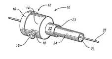
- FIG. 1is a perspective view of an introducer in accordance with an embodiment of the present invention
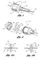
- FIG. 2is an exploded view of a proximal portion of an introducer in accordance with one embodiment of the present invention
- FIG. 3 ais a sectional view of the seal depicted in FIG. 2 in a first configuration
- FIG. 3 bis a sectional view of the seal depicted in FIG. 2 in a second configuration
- FIG. 4 ais an exploded view of a proximal portion of an introducer in accordance with another embodiment of the present invention.
- FIG. 4 bis a plan view of the seal depicted in FIG. 4 a in a first configuration
- FIG. 4 cis a plan view of the seal depicted in FIG. 4 a in a second configuration
- FIG. 5 ais an exploded view of an introducer kit in accordance with an embodiment of the present invention.
- FIG. 5 bis a side view of an introducer kit in accordance with an embodiment of the present invention.
- FIG. 6is a flow chart of a method for introducing a medical device into a body vessel of a patient in accordance with an example of the present invention.
- the present inventionseeks to overcome some of the problems associated with inserting a medical device into a body vessel of a patient via an introducer while providing for substantially leak-free passage of the medical device through the introducer.
- the present inventionprovides an introducer with a hemostatic valve seal, which is at least partially formed of shape memory polymers, and a method for using the introducer for introducing a medical device into a patient's body vessel which reduces or prevents body fluid from leaking through the seal.
- Shape memory polymersform polymeric material/s with the ability to sense and respond to external stimuli, e.g., temperature, pH, light, etc., in a predetermined way.
- Thermally induced shape memory polymersmay exhibit a one-way shape memory effect due to their distinct thermal dynamics and polymer structures.
- this one-way memory effectdiffers from many shape memory alloys which can exhibit modulating shape memory effects due to the reversible nature of their grain microstructures, e.g., alternating between martensite and austenite repeatedly in response to repeated temperature changes.
- shape memory polymershave polymer structures that can be considered as phase-segregated linear block copolymers having hard segments and soft segments.
- the hard segmente.g., cross-linked, highly crystalline or semi-crystalline segment, acts as the frozen phase and the soft segment, e.g., amorphous or semi-crystalline segment, acts as the reversible phase.
- the reversible phase transformation of the soft segmentis responsible for the shape memory effect.
- T(m)) or glass transition temperature (T(g)) of the hard segmentwhich is higher than the T(m) or T(g) of the soft segment, the material can be processed, e.g., molding, extrusion or the alike.
- T(m)is hereinafter understood to refer to the melting temperature or melting temperature range of the polymers (or polymer segments) where the polymer crystal lattice structures are no longer stable and/or free rotation and movement of the polymers (or polymer segments) readily occurs.
- T(g)is hereinafter understood to refer to the glass transition temperature or glass transition temperature range, e.g., softening temperature, of the polymers (or polymer segments) where some free rotation and/or movement of the polymers (or polymer segments) can occur.
- One method for forming a temporary shapeis by deforming the material in the remembered shape at a temperature below the T(m) or T(g) of the hard segment but above the T(m) or T(g) of the soft segment and then cooling the material below the T(m) or T(g) of the soft segment to fix the deformed shape.
- the remembered or original shapeis recovered by heating the shape memory polymer above the T(m) or T(g) of the soft segment, allowing at least some free rotation and/or movement of the soft segment for releasing the material from its temporary shape.
- Another method for setting the temporary shapeinvolves the material in the remembered shape being deformed at a temperature lower than the T(m) or T(g) of the soft segment, resulting in stress and strain being absorbed by the soft segment.
- the thermally induced shape memory polymers of the present inventionhave a one-way shape memory effect; they remember one permanent shape formed at the higher temperature, while many temporary shapes are possible at lower temperatures for which the systems do not have any memory because of the free rotation and/or movement of the soft segments.
- the present inventionemploys polymeric material having shape memory properties to form the hemostatic valve seal of the introducer.
- the temporary shape of the sealprovides an opening for advancing a medical device through the seal for insertion into the patient's body vessel and the remembered shape is a swollen or expanded shape to enhance sealing performance of the seal, reducing and/or preventing leakage of body fluid through the seal.
- the introducer 10includes a housing 12 .
- the housing 12comprises a main body 14 and an end cap 16 .
- Hard plastic or other suitably rigid and biocompatible materialmay be used to form the main body 14 and the end cap 15 .
- the main body 14 and the end cap 15may be joined together in any conventional fashion, such as by a screw fit or a snap fit.
- the embodiment in FIG. 2illustrates the main body 14 having one or more screw threads (grooves) 15 that may engage with one or more tabs 17 in the end cap 16 .
- the housing 12may also include a side-arm spout 18 extending in a generally transverse direction from the main housing body 14 .
- the spout 18may include a lip 19 that is sized and shaped for threaded engagement or alike with a tube 20 (shown in FIGS. 5 a and 5 b ) or other device, for use in the transmittal or aspiration of a fluid or a drug in a conventional fashion.
- the distal end of the housing body 14comprises a smaller diameter portion 22 that forms a distal opening 23 .
- a sheath 24which may be removable, extends distally from the small diameter portion 22 of the housing in a conventional fashion and is for being inserted into a body vessel of a patient.
- the sheath 24is preferably made of a flexible, biocompatible material and defines a conduit 30 for advancing a medical device therein for introduction to and retrieval from the body vessel.
- a guide wire 25is illustrated extending through the introducer 10 .
- one or more of the medical devicesare advanced to and from the body vessel over the guide wire 25 as is well known in the art.
- the end cap 16has a proximal opening 26 that is sized for passage of the medical device therethrough.
- a chamber 28is defined by the housing 12 and extends between the proximal opening 26 and the distal opening 23 .
- a hemostatic valve seal 32Disposed in the chamber 28 is a hemostatic valve seal 32 .
- the sealis made from polymeric material which is preferably compliant, e.g., elastomeric and soft with a Shore A hardness (Durometer) between about 20 to 100, and resistant to body fluid for suitable sealing characteristics.
- the seal 32has a form of a diaphragm and preferably extends to the inside perimeter surface of the housing 12 so that it is retained and/or constrained between an inside surface 34 of the end cap 16 and the perimeter edge 36 of the main body 14 , e.g., an outer perimeter portion of the seal 32 being sandwiched between the inside surface 34 and the perimeter edge 36 .
- the diaphragm form of the seal 32may substantially obstruct body fluid from flowing past the seal 32 through the proximal opening 26 of the introducer 10 .
- the seal 32has a first side 33 and a second side 35 that is opposite the first side 33 .
- the seal 32has a first slit 37 formed therein that extends from the first side 33 and a second slit 39 formed therein that extends from the second side 35 .
- a first configuration 38shown in FIG. 3 a and as will be discussed in further detail hereinafter
- the slits 37 and 39intersect to form an opening 40 which provides access through the seal 32 for advancing the medical device.
- the polymeric material of the seal 32is comprised of shape memory polymers.
- suitable polymerswhich may be formulated or polymerized to have shape memory effects are polyurethanes, polyester-urethanes, polyether-urethanes, polyesters, polyester-ethers, polyvinyl chlorides, silicones, and polyvinyl-alcohols.
- the polymeric materialmay include one of these types of polymers or these polymers may be blended or mixed to preferably form a relatively compliant material with good sealing capability and shape memory.
- the polymeric materialhas a first phase transition temperature, e.g., T(m) or T(g) of the hard segments of the shape memory polymers, and a second phase transition temperature, e.g., T(m) or T(g) of the soft segments of the shape memory polymers.
- the first phase transition temperatureis higher than about body temperature and the second phase transition temperature is less than the first phase transition temperature but is greater than about room temperature.
- Body temperatureis typically about 98.6 degrees Fahrenheit (OF) but may vary slightly depending on the wellbeing of the patient, preferably between about 95°-103° F. and more preferably between about 97°-101° F., and room temperature is typically about 65°-76° F. and more preferably between about 70°-72° F.
- the first phase transition temperatureis greater than about 106° F.
- the second phase transition temperatureis in the range of about 88-95° F.
- the seal 32When at about room temperature and as illustrated in FIG. 3 a , the seal 32 is in the first configuration 38 . That is, the first configuration 38 is the temporary shape.
- the first configuration 38is for advancing a medical device through the opening 40 of the seal 32 and into the conduit 30 of the sheath 24 .
- the opening 40 of the seal 32is sized to facilitate advancing the medical device over a guide wire 42 and through the seal 32 .
- a small gap 44may exist between the seal 32 and the guide wire 42 when the guide wire 42 is disposed through the opening 40 .
- the gap 44may help to reduce both resistance to advancing the medical device through the opening 40 as well as hoop stresses and strains imparted to the advancing medical device.
- the seal 32in at least one embodiment self-configures to a second configuration 46 when at a temperature of at least the second phase transition temperature due to the shape memory properties of the polymeric material. That is, the second configuration 46 is the remembered shape.
- the second configuration 46preferably has a shape for restricting and/or obstructing body fluid from the patient's body vessel from flowing through the opening 40 of the seal 32 , e.g., reducing or eliminating the gap/s 44 .
- the seal 32 in the second configuration 46is expanded relative to the first configuration 38 to a swollen state.
- the seal 32has an expanded central portion 48 about the opening 40 and an outer perimeter portion 50 , which may remain substantially unexpanded due to being sandwiched and constrained between the inside surface 34 of the end cap 16 and the perimeter edge 36 of the main body 14 and/or being intentionally deformed as such during the shape memorization process. It is believed that the unexpanded outer perimeter portion 50 may further swell the expanded central portion 48 by concentrating the entire seal's volumetric expansion inwardly towards the central portion 48 , e.g., via a Poisson's effect.
- the first and second slits 37 and 39become compressed and restrict and/or close up the opening 40 of the seal 32 . If a guide wire 25 or other medical device is disposed within the opening 40 , the opening 40 will be prevented from closing up but may constrict about the guide wire 25 and/or medical device to form a compressing inner portion 52 disposed about the opening 40 to form a substantially leak-tight interface with the guide wire 25 and/or medical device.
- the seal 32may include a plurality of valve members 54 that are packed together and axially aligned in the chamber 28 .
- Each of the valve members 54has an aperture 56 formed therethrough.
- the opening 40 of the seal 32is formed by axial alignment of the apertures 56 and more preferably, only partial axial alignment of the apertures 56 . That is, the apertures 56 are preferably substantially non-coaxial and partially offset from the center 58 of each of the valve members 54 with only a portion of each of the apertures 56 being coaxial and centered 58 .
- valve members 54may have locator features 60 which correspond to the tabs 17 of the main body 14 for defining the radial orientation of each of the valve members 54 .
- the seal 32self-configures to the second configuration 46 when at a temperature of at least the second phase transition temperature.
- the swollen shape of the seal 32 in the second configuration 46is formed by the expansion of each of the valve members 54 due the shape memory effect, thereby reducing the sizes of the apertures 56 .
- the portions of the apertures 56 that are coaxial and centered 58are preferably reduced or eliminated and thus, the apertures 56 may be further or completely non-coaxial and non-centered.
- the apertures 56will still be urged to misalign but the size of the opening 40 will instead be restricted to form a substantially leak-tight interface between the seal 40 and the guide wire 25 and/or medical device.
- the shape memory polymersare plasticized when contacted with body fluid, reducing the corresponding T(g) or T(m) of the soft segments, i.e., decreasing the temperature of the second phase transition temperature.
- the shape memory polymersmay be formulated to have limited or controlled body fluid permeability, e.g., water permeability.
- the water absorptivity of shape memory polyurethanes (SMPUs)is influenced by the mixed polyol blocks formed therein (e.g. urethanes may be formed from polyols and isocyanates) owing to their difference in microstructure. These blocks, e.g.
- This embodimentmay offer some advantages for packaging, shipping and handling of the introducer 10 without prematurely causing the seal 32 to self-configure to the second configuration 46 due to elevated environmental temperatures outside of the patient's body.
- the kit 70comprises the introducer 10 and the guide wire 25 as discussed in the foregoing paragraphs.
- the kit 70may also include a needle 72 for forming percutaneous access for the guide wire 25 into the body vessel.
- the needle 72may be used to form a surgical opening through the skin and into an artery or vein and the guide wire 25 may be inserted into the artery or vein through a bore in the needle 72 .
- the kit 70includes a dilator 74 .
- the dilator 74is elongated and has an outer diameter that is sized to fit through the introducer 10 including the opening 40 of the seal 32 and the conduit 30 of the sheath 24 .
- the dilator 74has an open distal end 76 that is tapered. When the dilator 74 is disposed through the introducer 10 , the distal end 76 of the dilator 74 projects distally from the sheath 24 of the introducer 10 as illustrated in FIG. 5 b .
- the taper open distal end 76 of the dilator 74provides a transitional lead for the introducer 10 to facilitate insertion of the sheath 24 over the guide wire 25 into the body vessel.
- a method for inserting a medical device into a body vessel of a patient in accordance with an example of the present inventioncomprises positioning a distal portion of a guide wire at 100 in the body vessel of a patient.
- the body vesselcontains body fluid.
- a dilatoris inserted at 102 through an opening formed through a seal of an introducer.
- the introducerincludes a sheath that extends distally therefrom.
- the dilatoris received by the sheath.
- the sealis in diaphragm form and is formed of shape memory polymers.
- the shape memory polymershave a first phase transition temperature, which is higher than about body temperature, and a second phase transition temperature, which is less than the first phase transition temperature but is greater than about room temperature.
- the sealis in a first configuration and is below the second phase transition temperature.
- the dilator and the sheathare cooperatively advanced distally along the guide wire to insert the sheath into the body vessel at 104 .
- the sealis heated at 106 to at least the second phase transition temperature where it self-configures to a second configuration to obstruct the body fluid from flowing through the opening of the seal.
- the step of heating the sealincludes warming the seal with the body fluid.
- the step of heating the seal to at least the second phase transition temperatureincludes contacting the seal with body fluid where the shape memory polymers are plasticized to reduce the second phase transition temperature.
Landscapes
- Health & Medical Sciences (AREA)
- Heart & Thoracic Surgery (AREA)
- Pulmonology (AREA)
- Engineering & Computer Science (AREA)
- Anesthesiology (AREA)
- Biomedical Technology (AREA)
- Hematology (AREA)
- Life Sciences & Earth Sciences (AREA)
- Animal Behavior & Ethology (AREA)
- General Health & Medical Sciences (AREA)
- Public Health (AREA)
- Veterinary Medicine (AREA)
- Infusion, Injection, And Reservoir Apparatuses (AREA)
Abstract
Description
Claims (21)
Priority Applications (1)
| Application Number | Priority Date | Filing Date | Title |
|---|---|---|---|
| US12/203,211US8308692B2 (en) | 2008-09-03 | 2008-09-03 | Introducer for use in inserting a medical device into a body vessel and method for same |
Applications Claiming Priority (1)
| Application Number | Priority Date | Filing Date | Title |
|---|---|---|---|
| US12/203,211US8308692B2 (en) | 2008-09-03 | 2008-09-03 | Introducer for use in inserting a medical device into a body vessel and method for same |
Publications (2)
| Publication Number | Publication Date |
|---|---|
| US20100057009A1 US20100057009A1 (en) | 2010-03-04 |
| US8308692B2true US8308692B2 (en) | 2012-11-13 |
Family
ID=41726459
Family Applications (1)
| Application Number | Title | Priority Date | Filing Date |
|---|---|---|---|
| US12/203,211Active2031-04-25US8308692B2 (en) | 2008-09-03 | 2008-09-03 | Introducer for use in inserting a medical device into a body vessel and method for same |
Country Status (1)
| Country | Link |
|---|---|
| US (1) | US8308692B2 (en) |
Cited By (5)
| Publication number | Priority date | Publication date | Assignee | Title |
|---|---|---|---|---|
| US8608724B2 (en) | 2004-07-19 | 2013-12-17 | Broncus Medical Inc. | Devices for delivering substances through an extra-anatomic opening created in an airway |
| US10322275B2 (en) | 2015-10-30 | 2019-06-18 | ECMOtek, LLC | Devices for endovascular access through extracorporeal life support circuits |
| US10737085B2 (en) | 2017-05-05 | 2020-08-11 | Greatbatch Ltd. | Medical device with hemostatic valve |
| US11413427B2 (en) | 2018-02-08 | 2022-08-16 | Pacesetter, Inc. | Introducer hub assembly having cross-slit seal |
| USRE50347E1 (en) | 2015-10-30 | 2025-03-25 | ECMOtek, LLC | Devices for endovascular access through extracorporeal life support circuits |
Families Citing this family (20)
| Publication number | Priority date | Publication date | Assignee | Title |
|---|---|---|---|---|
| US20100249518A1 (en)* | 2009-03-24 | 2010-09-30 | Battles Christopher A | Three piece elastic disk |
| US9282994B2 (en)* | 2009-09-25 | 2016-03-15 | St. Jude Medical Puerto Rico Llc | Vascular access to closure sheath and methods |
| US9775982B2 (en) | 2010-12-29 | 2017-10-03 | Medtronic, Inc. | Implantable medical device fixation |
| US10112045B2 (en) | 2010-12-29 | 2018-10-30 | Medtronic, Inc. | Implantable medical device fixation |
| US9393042B2 (en)* | 2011-06-01 | 2016-07-19 | Applied Medical Resources Corporation | Coaxial trocar seals havng sequential adjacent openings |
| US9339197B2 (en) | 2012-03-26 | 2016-05-17 | Medtronic, Inc. | Intravascular implantable medical device introduction |
| US9854982B2 (en) | 2012-03-26 | 2018-01-02 | Medtronic, Inc. | Implantable medical device deployment within a vessel |
| US9833625B2 (en) | 2012-03-26 | 2017-12-05 | Medtronic, Inc. | Implantable medical device delivery with inner and outer sheaths |
| US9717421B2 (en) | 2012-03-26 | 2017-08-01 | Medtronic, Inc. | Implantable medical device delivery catheter with tether |
| US10485435B2 (en)* | 2012-03-26 | 2019-11-26 | Medtronic, Inc. | Pass-through implantable medical device delivery catheter with removeable distal tip |
| US9220906B2 (en) | 2012-03-26 | 2015-12-29 | Medtronic, Inc. | Tethered implantable medical device deployment |
| US20150230694A1 (en)* | 2014-02-18 | 2015-08-20 | Munson Labs | Gas tight guide for bronchoscope and related devices |
| US10265433B2 (en)* | 2015-03-18 | 2019-04-23 | Lawrence Livermore National Security, Llc | Hemorrhage management system |
| US10675114B2 (en) | 2016-09-26 | 2020-06-09 | Spiway Llc | Access sheath for brain surgery |
| JP7509757B2 (en)* | 2018-09-17 | 2024-07-02 | アルコン インコーポレイティド | Low-friction trocar valve |
| US10874850B2 (en) | 2018-09-28 | 2020-12-29 | Medtronic, Inc. | Impedance-based verification for delivery of implantable medical devices |
| DE102018219360A1 (en)* | 2018-11-13 | 2020-05-14 | B. Braun Melsungen Ag | Dilator for widening a puncture channel during catheterization |
| US12151100B2 (en) | 2019-05-07 | 2024-11-26 | Medtronic, Inc. | Tether assemblies for medical device delivery systems |
| US11331475B2 (en) | 2019-05-07 | 2022-05-17 | Medtronic, Inc. | Tether assemblies for medical device delivery systems |
| US11413068B2 (en)* | 2019-05-09 | 2022-08-16 | Covidien Lp | Seal assemblies for surgical access assemblies |
Citations (78)
| Publication number | Priority date | Publication date | Assignee | Title |
|---|---|---|---|---|
| US2321336A (en) | 1942-08-10 | 1943-06-08 | Albert W Tondreau | Valve |
| US2416391A (en) | 1945-08-18 | 1947-02-25 | Wyeth Corp | Fluid transfer apparatus |
| US2844351A (en) | 1953-04-17 | 1958-07-22 | Baxter Don Inc | Fluid flow control |
| US3185179A (en) | 1961-05-05 | 1965-05-25 | Pharmaseal Lab | Disposable valve |
| US3304934A (en) | 1964-09-29 | 1967-02-21 | Dionisio O Bautista | Blood drawing device |
| US3329390A (en) | 1965-02-18 | 1967-07-04 | Eldon E Hulsey | Variable orifice valve |
| US3599637A (en) | 1969-05-12 | 1971-08-17 | Boris Schwartz | Intravenous catheter assembly |
| US4000739A (en) | 1975-07-09 | 1977-01-04 | Cordis Corporation | Hemostasis cannula |
| US4016879A (en) | 1973-08-22 | 1977-04-12 | Dynasciences Corporation | Multi-mode cannulating apparatus |
| US4063555A (en) | 1975-01-24 | 1977-12-20 | Aktiebolaget Stille-Werner | Cannula assembly |
| US4243034A (en) | 1978-10-17 | 1981-01-06 | Viggo Ab | Cannula or catheter assembly |
| US4311137A (en) | 1980-04-30 | 1982-01-19 | Sherwood Medical Industries Inc. | Infusion device |
| US4314555A (en) | 1979-02-20 | 1982-02-09 | Terumo Corporation | Intravascular catheter assembly |
| US4424833A (en) | 1981-10-02 | 1984-01-10 | C. R. Bard, Inc. | Self sealing gasket assembly |
| US4540411A (en) | 1983-11-28 | 1985-09-10 | Sherwood Medical Company | Catheter placement device |
| US4580573A (en) | 1983-10-20 | 1986-04-08 | Medical Device Development Corporation, Inc. | Catheter introducer |
| US4610674A (en) | 1984-09-13 | 1986-09-09 | Terumo Kabushi Kaisha | Catheter introducing instrument |
| US4610665A (en) | 1983-01-18 | 1986-09-09 | Terumo Kabushiki Kaisha | Medical instrument |
| US4626245A (en) | 1985-08-30 | 1986-12-02 | Cordis Corporation | Hemostatis valve comprising an elastomeric partition having opposed intersecting slits |
| US4629450A (en) | 1984-05-09 | 1986-12-16 | Terumo Corporation | Catheter introducing instrument |
| US4798594A (en) | 1987-09-21 | 1989-01-17 | Cordis Corporation | Medical instrument valve |
| US4895565A (en) | 1987-09-21 | 1990-01-23 | Cordis Corporation | Medical instrument valve |
| US4929235A (en) | 1985-07-31 | 1990-05-29 | Universal Medical Instrument Corp. | Self-sealing percutaneous tube introducer |
| US4932633A (en) | 1988-11-21 | 1990-06-12 | Schneider-Shiley (U.S.A.) Inc. | Hemostasis valve |
| US4978341A (en) | 1988-04-07 | 1990-12-18 | Schneider Europe | Introducer valve for a catheter arrangement |
| US5000745A (en) | 1988-11-18 | 1991-03-19 | Edward Weck Incorporated | Hemostatis valve |
| US5006113A (en) | 1990-02-08 | 1991-04-09 | Cook Incorporated | Hemostasis cannula |
| US5009391A (en) | 1988-05-02 | 1991-04-23 | The Kendall Company | Valve assembly |
| US5053013A (en) | 1990-03-01 | 1991-10-01 | The Regents Of The University Of Michigan | Implantable infusion device |
| US5066285A (en) | 1990-01-26 | 1991-11-19 | Cordis Corporation | Catheter introducer sheath made of expanded polytetrafluoroethylene |
| US5102395A (en) | 1991-06-26 | 1992-04-07 | Adam Spence Corporation | Hemostasis valve |
| US5125903A (en) | 1991-08-01 | 1992-06-30 | Medtronic, Inc. | Hemostasis valve |
| US5154701A (en) | 1991-06-26 | 1992-10-13 | Adam Spence Corporation | Hemostasis valve |
| US5158553A (en) | 1990-12-26 | 1992-10-27 | Cardiopulmonics | Rotatably actuated constricting catheter valve |
| US5167637A (en) | 1990-11-01 | 1992-12-01 | Sherwood Medical Company | Valve membrane for a catheter introducer hemostatic valve |
| US5176652A (en) | 1989-12-22 | 1993-01-05 | Cordis Corporation | Hemostasis valve |
| US5211370A (en) | 1992-01-06 | 1993-05-18 | Powers Ronald J | Variable orifice sealing valve |
| EP0550069A1 (en) | 1992-01-03 | 1993-07-07 | United States Surgical Corporation | Variable interior dimension cannula assembly |
| US5242413A (en) | 1991-08-21 | 1993-09-07 | Vygon Gmbh & Co. Kg | Disc valve for a catheter |
| US5256150A (en) | 1991-12-13 | 1993-10-26 | Endovascular Technologies, Inc. | Large-diameter expandable sheath and method |
| US5267966A (en) | 1992-09-28 | 1993-12-07 | Cook Incorporated | Hemostasis cannula and method of making a valve for same |
| US5304156A (en) | 1988-06-02 | 1994-04-19 | C. R. Bard, Inc. | Self-sealing guidewire and catheter introducer |
| US5350364A (en) | 1991-10-18 | 1994-09-27 | Ethicon, Inc. | Universal seal for trocar assembly |
| US5350363A (en) | 1993-06-14 | 1994-09-27 | Cordis Corporation | Enhanced sheath valve |
| US5376077A (en) | 1992-12-04 | 1994-12-27 | Interventional Technologies, Inc. | Introducer sheath with seal protector |
| US5395349A (en) | 1991-12-13 | 1995-03-07 | Endovascular Technologies, Inc. | Dual valve reinforced sheath and method |
| US5395352A (en) | 1992-02-24 | 1995-03-07 | Scimed Lift Systems, Inc. | Y-adaptor manifold with pinch valve for an intravascular catheter |
| US5409463A (en) | 1992-06-05 | 1995-04-25 | Thomas Medical Products, Inc. | Catheter introducer with lubrication means |
| US5538505A (en) | 1993-06-14 | 1996-07-23 | Cordis Corporation | Hemostasis valve for catheter introducer having thickened central partition section |
| EP0755694A1 (en) | 1995-07-27 | 1997-01-29 | Cordis Corporation | Guiding catheter introducer assembly |
| US5613956A (en) | 1993-05-07 | 1997-03-25 | C. R. Bard, Inc. | Catheter introducer |
| US5643227A (en) | 1995-01-19 | 1997-07-01 | Stevens; Robert C. | Hemostasis cannula valve apparatus and method of using same |
| US5779681A (en) | 1991-12-16 | 1998-07-14 | Thomas Jefferson University | Vascular access sheath for interventional devices |
| EP0344907B1 (en) | 1988-06-02 | 1998-09-16 | C.R. Bard, Inc. | Self-sealing guidewire and catheter introducer |
| US5833706A (en) | 1991-07-05 | 1998-11-10 | Scimed Life Systems, Inc. | Single operator exchange perfusion catheter having a distal catheter shaft section |
| US5895376A (en) | 1996-10-23 | 1999-04-20 | Mayo Foundation For Medical Education And Research | Hemostasis valve, system and assembly |
| WO1999026682A1 (en) | 1997-09-26 | 1999-06-03 | Cordis Corporation | Intravascular catheter system with convertible sheath extension for magnetic resonance imaging and method |
| US5935122A (en) | 1991-12-13 | 1999-08-10 | Endovascular Technologies, Inc. | Dual valve, flexible expandable sheath and method |
| US6004280A (en) | 1997-08-05 | 1999-12-21 | Cordis Corporation | Guiding sheath having three-dimensional distal end |
| US6086570A (en) | 1998-09-29 | 2000-07-11 | A-Med Systems, Inc. | Hemostasis valve with membranes having offset apertures |
| US6152144A (en) | 1998-11-06 | 2000-11-28 | Appriva Medical, Inc. | Method and device for left atrial appendage occlusion |
| US6183443B1 (en)* | 1992-10-15 | 2001-02-06 | Scimed Life Systems, Inc. | Expandable introducer sheath |
| US6276661B1 (en) | 1996-11-06 | 2001-08-21 | Medtronic, Inc. | Pressure actuated introducer valve |
| US6416499B2 (en) | 1997-07-30 | 2002-07-09 | Cook Incorporated | Medical fluid flow control valve |
| US6562049B1 (en) | 2000-03-01 | 2003-05-13 | Cook Vascular Incorporated | Medical introducer apparatus |
| US20030144670A1 (en) | 2001-11-29 | 2003-07-31 | Cook Incorporated | Medical device delivery system |
| US6610031B1 (en) | 2001-04-18 | 2003-08-26 | Origin Medsystems, Inc. | Valve assembly |
| US20030187397A1 (en)* | 2002-03-29 | 2003-10-02 | Dario Vitali | Trocar with a reinforced seal |
| US20030216771A1 (en) | 2002-03-15 | 2003-11-20 | Thomas P. Osypka | Locking vascular introducer assembly with adjustable hemostatic seal |
| EP1374942A1 (en) | 2002-06-26 | 2004-01-02 | Medikit Co., Ltd. | Indwelling catheter set |
| US20050096692A1 (en) | 2003-09-12 | 2005-05-05 | Linder Richard J. | Methods, systems, and devices for providing embolic protection and removing embolic material |
| US20050096605A1 (en) | 1992-04-24 | 2005-05-05 | Green David T. | Valve assembly for introducing instruments into body cavities |
| US20050171479A1 (en) | 2003-12-11 | 2005-08-04 | Hruska Christopher L. | Hemostatic valve assembly |
| US20050230925A1 (en)* | 2004-03-12 | 2005-10-20 | Browne Alan L | Releasable seal assemblies and methods of use |
| US6981966B2 (en) | 1991-10-18 | 2006-01-03 | United States Surgical | Valve assembly for introducing instruments into body cavities |
| US20070060911A1 (en) | 2005-08-18 | 2007-03-15 | Lumen Biomedical, Inc. | Rapid exchange catheter |
| US20070078395A1 (en) | 2005-09-09 | 2007-04-05 | Cook Incorporated | Hemostatic valve system |
| US20070276461A1 (en) | 2001-12-03 | 2007-11-29 | Xtent, Inc. | Delivery catheter having active engagement mechanism for prosthesis |
- 2008
- 2008-09-03USUS12/203,211patent/US8308692B2/enactiveActive
Patent Citations (83)
| Publication number | Priority date | Publication date | Assignee | Title |
|---|---|---|---|---|
| US2321336A (en) | 1942-08-10 | 1943-06-08 | Albert W Tondreau | Valve |
| US2416391A (en) | 1945-08-18 | 1947-02-25 | Wyeth Corp | Fluid transfer apparatus |
| US2844351A (en) | 1953-04-17 | 1958-07-22 | Baxter Don Inc | Fluid flow control |
| US3185179A (en) | 1961-05-05 | 1965-05-25 | Pharmaseal Lab | Disposable valve |
| US3304934A (en) | 1964-09-29 | 1967-02-21 | Dionisio O Bautista | Blood drawing device |
| US3329390A (en) | 1965-02-18 | 1967-07-04 | Eldon E Hulsey | Variable orifice valve |
| US3599637A (en) | 1969-05-12 | 1971-08-17 | Boris Schwartz | Intravenous catheter assembly |
| US4016879A (en) | 1973-08-22 | 1977-04-12 | Dynasciences Corporation | Multi-mode cannulating apparatus |
| US4063555A (en) | 1975-01-24 | 1977-12-20 | Aktiebolaget Stille-Werner | Cannula assembly |
| US4000739A (en) | 1975-07-09 | 1977-01-04 | Cordis Corporation | Hemostasis cannula |
| US4243034A (en) | 1978-10-17 | 1981-01-06 | Viggo Ab | Cannula or catheter assembly |
| US4314555A (en) | 1979-02-20 | 1982-02-09 | Terumo Corporation | Intravascular catheter assembly |
| US4311137A (en) | 1980-04-30 | 1982-01-19 | Sherwood Medical Industries Inc. | Infusion device |
| US4424833A (en) | 1981-10-02 | 1984-01-10 | C. R. Bard, Inc. | Self sealing gasket assembly |
| US4610665A (en) | 1983-01-18 | 1986-09-09 | Terumo Kabushiki Kaisha | Medical instrument |
| US4580573A (en) | 1983-10-20 | 1986-04-08 | Medical Device Development Corporation, Inc. | Catheter introducer |
| US4540411A (en) | 1983-11-28 | 1985-09-10 | Sherwood Medical Company | Catheter placement device |
| US4629450A (en) | 1984-05-09 | 1986-12-16 | Terumo Corporation | Catheter introducing instrument |
| US4610674A (en) | 1984-09-13 | 1986-09-09 | Terumo Kabushi Kaisha | Catheter introducing instrument |
| US4929235A (en) | 1985-07-31 | 1990-05-29 | Universal Medical Instrument Corp. | Self-sealing percutaneous tube introducer |
| US4626245A (en) | 1985-08-30 | 1986-12-02 | Cordis Corporation | Hemostatis valve comprising an elastomeric partition having opposed intersecting slits |
| US4798594A (en) | 1987-09-21 | 1989-01-17 | Cordis Corporation | Medical instrument valve |
| US4895565A (en) | 1987-09-21 | 1990-01-23 | Cordis Corporation | Medical instrument valve |
| US4978341A (en) | 1988-04-07 | 1990-12-18 | Schneider Europe | Introducer valve for a catheter arrangement |
| US5009391A (en) | 1988-05-02 | 1991-04-23 | The Kendall Company | Valve assembly |
| US5304156A (en) | 1988-06-02 | 1994-04-19 | C. R. Bard, Inc. | Self-sealing guidewire and catheter introducer |
| US5702370A (en) | 1988-06-02 | 1997-12-30 | C. R. Bard, Inc. | Self-sealing guidewire and catheter introducer |
| EP0344907B1 (en) | 1988-06-02 | 1998-09-16 | C.R. Bard, Inc. | Self-sealing guidewire and catheter introducer |
| US5000745A (en) | 1988-11-18 | 1991-03-19 | Edward Weck Incorporated | Hemostatis valve |
| US4932633A (en) | 1988-11-21 | 1990-06-12 | Schneider-Shiley (U.S.A.) Inc. | Hemostasis valve |
| US5176652A (en) | 1989-12-22 | 1993-01-05 | Cordis Corporation | Hemostasis valve |
| US5066285A (en) | 1990-01-26 | 1991-11-19 | Cordis Corporation | Catheter introducer sheath made of expanded polytetrafluoroethylene |
| US5006113A (en) | 1990-02-08 | 1991-04-09 | Cook Incorporated | Hemostasis cannula |
| US5053013A (en) | 1990-03-01 | 1991-10-01 | The Regents Of The University Of Michigan | Implantable infusion device |
| US5167637A (en) | 1990-11-01 | 1992-12-01 | Sherwood Medical Company | Valve membrane for a catheter introducer hemostatic valve |
| US5158553A (en) | 1990-12-26 | 1992-10-27 | Cardiopulmonics | Rotatably actuated constricting catheter valve |
| US5154701A (en) | 1991-06-26 | 1992-10-13 | Adam Spence Corporation | Hemostasis valve |
| US5102395A (en) | 1991-06-26 | 1992-04-07 | Adam Spence Corporation | Hemostasis valve |
| US5833706A (en) | 1991-07-05 | 1998-11-10 | Scimed Life Systems, Inc. | Single operator exchange perfusion catheter having a distal catheter shaft section |
| US5125903A (en) | 1991-08-01 | 1992-06-30 | Medtronic, Inc. | Hemostasis valve |
| US5242413A (en) | 1991-08-21 | 1993-09-07 | Vygon Gmbh & Co. Kg | Disc valve for a catheter |
| US6981966B2 (en) | 1991-10-18 | 2006-01-03 | United States Surgical | Valve assembly for introducing instruments into body cavities |
| US5350364A (en) | 1991-10-18 | 1994-09-27 | Ethicon, Inc. | Universal seal for trocar assembly |
| US5256150A (en) | 1991-12-13 | 1993-10-26 | Endovascular Technologies, Inc. | Large-diameter expandable sheath and method |
| US5935122A (en) | 1991-12-13 | 1999-08-10 | Endovascular Technologies, Inc. | Dual valve, flexible expandable sheath and method |
| US5395349A (en) | 1991-12-13 | 1995-03-07 | Endovascular Technologies, Inc. | Dual valve reinforced sheath and method |
| US5484418A (en) | 1991-12-13 | 1996-01-16 | Endovascular Technologies, Inc. | Dual valve reinforced sheath and method |
| US6197016B1 (en) | 1991-12-13 | 2001-03-06 | Endovascular Technologies, Inc. | Dual valve, flexible expandable sheath and method |
| US5653697A (en) | 1991-12-13 | 1997-08-05 | Endovascular Technologies, Inc. | Dual valve reinforced sheath and method |
| US5779681A (en) | 1991-12-16 | 1998-07-14 | Thomas Jefferson University | Vascular access sheath for interventional devices |
| EP0550069A1 (en) | 1992-01-03 | 1993-07-07 | United States Surgical Corporation | Variable interior dimension cannula assembly |
| US5211370A (en) | 1992-01-06 | 1993-05-18 | Powers Ronald J | Variable orifice sealing valve |
| US5395352A (en) | 1992-02-24 | 1995-03-07 | Scimed Lift Systems, Inc. | Y-adaptor manifold with pinch valve for an intravascular catheter |
| US20050096605A1 (en) | 1992-04-24 | 2005-05-05 | Green David T. | Valve assembly for introducing instruments into body cavities |
| US5409463A (en) | 1992-06-05 | 1995-04-25 | Thomas Medical Products, Inc. | Catheter introducer with lubrication means |
| US5267966A (en) | 1992-09-28 | 1993-12-07 | Cook Incorporated | Hemostasis cannula and method of making a valve for same |
| US6183443B1 (en)* | 1992-10-15 | 2001-02-06 | Scimed Life Systems, Inc. | Expandable introducer sheath |
| US5376077A (en) | 1992-12-04 | 1994-12-27 | Interventional Technologies, Inc. | Introducer sheath with seal protector |
| US5613956A (en) | 1993-05-07 | 1997-03-25 | C. R. Bard, Inc. | Catheter introducer |
| US5350363A (en) | 1993-06-14 | 1994-09-27 | Cordis Corporation | Enhanced sheath valve |
| US5538505A (en) | 1993-06-14 | 1996-07-23 | Cordis Corporation | Hemostasis valve for catheter introducer having thickened central partition section |
| US5643227A (en) | 1995-01-19 | 1997-07-01 | Stevens; Robert C. | Hemostasis cannula valve apparatus and method of using same |
| EP0755694A1 (en) | 1995-07-27 | 1997-01-29 | Cordis Corporation | Guiding catheter introducer assembly |
| US5895376A (en) | 1996-10-23 | 1999-04-20 | Mayo Foundation For Medical Education And Research | Hemostasis valve, system and assembly |
| US6221057B1 (en) | 1996-10-23 | 2001-04-24 | Mayo Foundation For Medical Education And Research | Hemostasis valve, system and assembly |
| US6276661B1 (en) | 1996-11-06 | 2001-08-21 | Medtronic, Inc. | Pressure actuated introducer valve |
| US6416499B2 (en) | 1997-07-30 | 2002-07-09 | Cook Incorporated | Medical fluid flow control valve |
| US6004280A (en) | 1997-08-05 | 1999-12-21 | Cordis Corporation | Guiding sheath having three-dimensional distal end |
| WO1999026682A1 (en) | 1997-09-26 | 1999-06-03 | Cordis Corporation | Intravascular catheter system with convertible sheath extension for magnetic resonance imaging and method |
| US6086570A (en) | 1998-09-29 | 2000-07-11 | A-Med Systems, Inc. | Hemostasis valve with membranes having offset apertures |
| US6152144A (en) | 1998-11-06 | 2000-11-28 | Appriva Medical, Inc. | Method and device for left atrial appendage occlusion |
| US6562049B1 (en) | 2000-03-01 | 2003-05-13 | Cook Vascular Incorporated | Medical introducer apparatus |
| US6610031B1 (en) | 2001-04-18 | 2003-08-26 | Origin Medsystems, Inc. | Valve assembly |
| US20030144670A1 (en) | 2001-11-29 | 2003-07-31 | Cook Incorporated | Medical device delivery system |
| US20070276461A1 (en) | 2001-12-03 | 2007-11-29 | Xtent, Inc. | Delivery catheter having active engagement mechanism for prosthesis |
| US20030216771A1 (en) | 2002-03-15 | 2003-11-20 | Thomas P. Osypka | Locking vascular introducer assembly with adjustable hemostatic seal |
| US20030187397A1 (en)* | 2002-03-29 | 2003-10-02 | Dario Vitali | Trocar with a reinforced seal |
| EP1374942A1 (en) | 2002-06-26 | 2004-01-02 | Medikit Co., Ltd. | Indwelling catheter set |
| US20050096692A1 (en) | 2003-09-12 | 2005-05-05 | Linder Richard J. | Methods, systems, and devices for providing embolic protection and removing embolic material |
| US20050171479A1 (en) | 2003-12-11 | 2005-08-04 | Hruska Christopher L. | Hemostatic valve assembly |
| US20050230925A1 (en)* | 2004-03-12 | 2005-10-20 | Browne Alan L | Releasable seal assemblies and methods of use |
| US20070060911A1 (en) | 2005-08-18 | 2007-03-15 | Lumen Biomedical, Inc. | Rapid exchange catheter |
| US20070078395A1 (en) | 2005-09-09 | 2007-04-05 | Cook Incorporated | Hemostatic valve system |
Cited By (9)
| Publication number | Priority date | Publication date | Assignee | Title |
|---|---|---|---|---|
| US8608724B2 (en) | 2004-07-19 | 2013-12-17 | Broncus Medical Inc. | Devices for delivering substances through an extra-anatomic opening created in an airway |
| US10322275B2 (en) | 2015-10-30 | 2019-06-18 | ECMOtek, LLC | Devices for endovascular access through extracorporeal life support circuits |
| US10441774B2 (en) | 2015-10-30 | 2019-10-15 | ECMOtek, LLC | Devices for endovascular access through extracorporeal life support circuits |
| US10576260B2 (en) | 2015-10-30 | 2020-03-03 | ECMOtek, LLC | Devices for endovascular access through extracorporeal life support circuits |
| USRE50347E1 (en) | 2015-10-30 | 2025-03-25 | ECMOtek, LLC | Devices for endovascular access through extracorporeal life support circuits |
| US10737085B2 (en) | 2017-05-05 | 2020-08-11 | Greatbatch Ltd. | Medical device with hemostatic valve |
| US11559676B2 (en) | 2017-05-05 | 2023-01-24 | Greatbatch Ltd. | Medical device with hemostatic valve |
| US11413427B2 (en) | 2018-02-08 | 2022-08-16 | Pacesetter, Inc. | Introducer hub assembly having cross-slit seal |
| US12296116B2 (en) | 2018-02-08 | 2025-05-13 | Pacesetter, Inc. | Introducer hub assembly having cross-slit seal |
Also Published As
| Publication number | Publication date |
|---|---|
| US20100057009A1 (en) | 2010-03-04 |
Similar Documents
| Publication | Publication Date | Title |
|---|---|---|
| US8308692B2 (en) | Introducer for use in inserting a medical device into a body vessel and method for same | |
| US12194249B2 (en) | Multiple-use intravenous catheter assembly septum and septum actuator | |
| US11701495B2 (en) | Methods and devices for vascular access | |
| AU745352B2 (en) | Medical fluid flow control valve | |
| AU2012318634B2 (en) | Multiple use stretching and non-penetrating blood control valves | |
| US10682157B2 (en) | Vascular access device | |
| AU2012318542B2 (en) | Multiple use blood control valve with center and circumferential slits | |
| US5125903A (en) | Hemostasis valve | |
| EP2967866B1 (en) | Mitral valve spacer | |
| BRPI0717558A2 (en) | VASCULAR ACCESS DEVICE CAMERA REPLACEMENT | |
| US11638806B2 (en) | Blood collection devices, systems, and methods | |
| US6432091B1 (en) | Valved over-the-wire catheter | |
| JP2009544449A (en) | Volume change vascular access device | |
| JP2003520652A (en) | Hemostatic valve | |
| WO1993011810A1 (en) | Introducer sheath having a hemostatic closure | |
| EP0442194A2 (en) | Cylindrical plug for sealing around guidewire | |
| US20130110086A1 (en) | Bulged catheter tip | |
| US20120078186A1 (en) | Catheter with expandable flow area |
Legal Events
| Date | Code | Title | Description |
|---|---|---|---|
| AS | Assignment | Owner name:COOK INCORPORATED,INDIANA Free format text:ASSIGNMENT OF ASSIGNORS INTEREST;ASSIGNORS:MCQUEEN, AMY;VALAIE, ARMAN H.;SIGNING DATES FROM 20080826 TO 20080902;REEL/FRAME:021472/0550 Owner name:COOK INCORPORATED, INDIANA Free format text:ASSIGNMENT OF ASSIGNORS INTEREST;ASSIGNORS:MCQUEEN, AMY;VALAIE, ARMAN H.;SIGNING DATES FROM 20080826 TO 20080902;REEL/FRAME:021472/0550 | |
| AS | Assignment | Owner name:COOK MEDICAL TECHNOLOGIES LLC, INDIANA Free format text:ASSIGNMENT OF ASSIGNORS INTEREST;ASSIGNOR:COOK INCORPORATED;REEL/FRAME:029095/0602 Effective date:20120822 | |
| STCF | Information on status: patent grant | Free format text:PATENTED CASE | |
| CC | Certificate of correction | ||
| FPAY | Fee payment | Year of fee payment:4 | |
| MAFP | Maintenance fee payment | Free format text:PAYMENT OF MAINTENANCE FEE, 8TH YEAR, LARGE ENTITY (ORIGINAL EVENT CODE: M1552); ENTITY STATUS OF PATENT OWNER: LARGE ENTITY Year of fee payment:8 | |
| AS | Assignment | Owner name:WILMINGTON TRUST, NATIONAL ASSOCIATION, AS COLLATERAL AGENT, DELAWARE Free format text:SECURITY INTEREST;ASSIGNOR:COOK MEDICAL TECHNOLOGIES LLC;REEL/FRAME:066700/0277 Effective date:20240227 | |
| MAFP | Maintenance fee payment | Free format text:PAYMENT OF MAINTENANCE FEE, 12TH YEAR, LARGE ENTITY (ORIGINAL EVENT CODE: M1553); ENTITY STATUS OF PATENT OWNER: LARGE ENTITY Year of fee payment:12 |