US8308361B2 - Cantilevered gantry apparatus for X-ray imaging - Google Patents
Cantilevered gantry apparatus for X-ray imagingDownload PDFInfo
- Publication number
- US8308361B2 US8308361B2US13/027,867US201113027867AUS8308361B2US 8308361 B2US8308361 B2US 8308361B2US 201113027867 AUS201113027867 AUS 201113027867AUS 8308361 B2US8308361 B2US 8308361B2
- Authority
- US
- United States
- Prior art keywords
- gantry
- positioner
- support structure
- ring
- imaging apparatus
- Prior art date
- Legal status (The legal status is an assumption and is not a legal conclusion. Google has not performed a legal analysis and makes no representation as to the accuracy of the status listed.)
- Expired - Fee Related
Links
- 238000003384imaging methodMethods0.000titleclaimsabstractdescription51
- 230000008713feedback mechanismEffects0.000claimsdescription3
- 238000003325tomographyMethods0.000claims2
- 238000002591computed tomographyMethods0.000abstract2
- 230000006870functionEffects0.000description5
- 238000000034methodMethods0.000description4
- 238000003491arrayMethods0.000description3
- 230000008901benefitEffects0.000description3
- 238000002059diagnostic imagingMethods0.000description3
- 238000010586diagramMethods0.000description3
- 238000005516engineering processMethods0.000description2
- 238000002594fluoroscopyMethods0.000description2
- 229910021417amorphous siliconInorganic materials0.000description1
- 238000004458analytical methodMethods0.000description1
- 210000003484anatomyAnatomy0.000description1
- 230000000712assemblyEffects0.000description1
- 238000000429assemblyMethods0.000description1
- 239000003795chemical substances by applicationSubstances0.000description1
- 230000008878couplingEffects0.000description1
- 238000010168coupling processMethods0.000description1
- 238000005859coupling reactionMethods0.000description1
- 238000003745diagnosisMethods0.000description1
- 238000007689inspectionMethods0.000description1
- 238000002595magnetic resonance imagingMethods0.000description1
- 239000000463materialSubstances0.000description1
- 230000007246mechanismEffects0.000description1
- 238000002600positron emission tomographyMethods0.000description1
- 230000005855radiationEffects0.000description1
- 238000002603single-photon emission computed tomographyMethods0.000description1
- 238000001356surgical procedureMethods0.000description1
- 230000001360synchronised effectEffects0.000description1
- 230000001225therapeutic effectEffects0.000description1
- 239000010409thin filmSubstances0.000description1
- 238000002604ultrasonographyMethods0.000description1
- 238000012285ultrasound imagingMethods0.000description1
Images


Classifications
- A—HUMAN NECESSITIES
- A61—MEDICAL OR VETERINARY SCIENCE; HYGIENE
- A61B—DIAGNOSIS; SURGERY; IDENTIFICATION
- A61B6/00—Apparatus or devices for radiation diagnosis; Apparatus or devices for radiation diagnosis combined with radiation therapy equipment
- A61B6/44—Constructional features of apparatus for radiation diagnosis
- A61B6/4429—Constructional features of apparatus for radiation diagnosis related to the mounting of source units and detector units
- A61B6/4435—Constructional features of apparatus for radiation diagnosis related to the mounting of source units and detector units the source unit and the detector unit being coupled by a rigid structure
- A61B6/4447—Tiltable gantries
- A—HUMAN NECESSITIES
- A61—MEDICAL OR VETERINARY SCIENCE; HYGIENE
- A61B—DIAGNOSIS; SURGERY; IDENTIFICATION
- A61B6/00—Apparatus or devices for radiation diagnosis; Apparatus or devices for radiation diagnosis combined with radiation therapy equipment
- A61B6/02—Arrangements for diagnosis sequentially in different planes; Stereoscopic radiation diagnosis
- A61B6/03—Computed tomography [CT]
- A61B6/032—Transmission computed tomography [CT]
- A61B6/035—Mechanical aspects of CT
- A—HUMAN NECESSITIES
- A61—MEDICAL OR VETERINARY SCIENCE; HYGIENE
- A61B—DIAGNOSIS; SURGERY; IDENTIFICATION
- A61B6/00—Apparatus or devices for radiation diagnosis; Apparatus or devices for radiation diagnosis combined with radiation therapy equipment
- A61B6/44—Constructional features of apparatus for radiation diagnosis
- A61B6/4405—Constructional features of apparatus for radiation diagnosis the apparatus being movable or portable, e.g. handheld or mounted on a trolley
- A—HUMAN NECESSITIES
- A61—MEDICAL OR VETERINARY SCIENCE; HYGIENE
- A61N—ELECTROTHERAPY; MAGNETOTHERAPY; RADIATION THERAPY; ULTRASOUND THERAPY
- A61N5/00—Radiation therapy
- A61N5/10—X-ray therapy; Gamma-ray therapy; Particle-irradiation therapy
- A—HUMAN NECESSITIES
- A61—MEDICAL OR VETERINARY SCIENCE; HYGIENE
- A61N—ELECTROTHERAPY; MAGNETOTHERAPY; RADIATION THERAPY; ULTRASOUND THERAPY
- A61N5/00—Radiation therapy
- A61N5/10—X-ray therapy; Gamma-ray therapy; Particle-irradiation therapy
- A61N5/1077—Beam delivery systems
- A61N5/1081—Rotating beam systems with a specific mechanical construction, e.g. gantries
- A61N5/1082—Rotating beam systems with a specific mechanical construction, e.g. gantries having multiple beam rotation axes
- G—PHYSICS
- G01—MEASURING; TESTING
- G01N—INVESTIGATING OR ANALYSING MATERIALS BY DETERMINING THEIR CHEMICAL OR PHYSICAL PROPERTIES
- G01N2223/00—Investigating materials by wave or particle radiation
- G01N2223/40—Imaging
- G01N2223/419—Imaging computed tomograph
Definitions
- the fluoroscopic C-arm attemptsmeet the criteria of mobility and flexibility, but fall short on image quality and image volume.
- the “mobile CT scanner” attemptsmeet the criteria of image volume and quality, but fail to address the practical issues of usability and cost. Additionally, state of the art CT scanners are incapable of translating and tilting in the same fashion of mobile fluoroscopy systems.
- the present inventionis directed to an imaging apparatus comprising a generally O-shaped gantry ring having an x-ray source and a detector.
- the gantry ringis rigidly or movably secured on one side of the ring to a support structure, such as a mobile cart, a wall, a ceiling, a floor, or a patient table, in a cantilevered fashion.
- a positioner assemblycan secure the gantry ring to the support structure in a cantilevered fashion, the positioner assembly permitting the gantry to translate in at least one direction, and/or rotate around at least one axis, relative to the support structure.
- the x-ray sourceis contained inside the gantry ring, opposed to a detector array.
- the x-ray source(and optionally the detector) can rotate around the inside of the gantry ring, preferably through a full or partial 360 degree scan around the interior of the gantry.
- the imaging apparatusis particularly advantageous for medical imaging applications, including 3D computerized tomographic (CT) imaging and 2D x-ray radiographic scanning, as well as other medical, scientific, and industrial applications.
- CTcomputerized tomographic
- a method for imaging an object with an imaging system having a substantially O-shaped gantry secured to a support structure in a cantilevered fashion by a ring positioning unitcomprises positioning the object within a central opening of the generally O-shaped gantry; operating the ring positioning unit to position the gantry at a predetermined position and orientation relative to the support structure; and obtaining an image of the object.
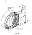
- FIG. 1is a schematic diagram of a mobile x-ray scanning system with a cantilevered O-shaped gantry according to one embodiment of the invention
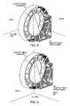
- FIG. 2shows the scanning system of FIG. 1 with the cantilevered O-shaped gantry in a translated and tilted position via a ring positioning unit;
- FIG. 3shows a gantry ring positioning unit for translating a gantry in three directions and tilting the gantry with respect to one axis, according to one aspect of the invention
- FIG. 4shows a ring positioning unit for translating the gantry ring in an in/out direction
- FIG. 5shows a ring positioning unit for translating the gantry in a vertical direction
- FIG. 6shows a ring positioning unit for translating the gantry in a lateral direction
- FIG. 7shows a ring positioning unit for tilting the gantry with respect to one axis
- FIG. 8shows a floor-mounted cantilevered gantry ring with ring positioning unit
- FIG. 9shows a wall-mounted cantilevered gantry ring with ring positioning unit
- FIG. 10shows a ceiling-mounted cantilevered gantry ring with ring positioning unit.
- FIG. 1is a schematic diagram showing an x-ray scanning system 10 in accordance with one embodiment of the invention.
- the x-ray scanning system 10includes a gantry 11 secured to a support structure, which could be a mobile or stationary cart, a patient table, a wall, a floor, or a ceiling.
- a support structurewhich could be a mobile or stationary cart, a patient table, a wall, a floor, or a ceiling.
- the gantry 11is secured to a mobile cart 12 in a cantilevered fashion via a ring positioning unit 20 .
- the ring positioning unit 20can translate and/or tilt the gantry 11 with respect to the support structure to position the gantry 11 in any number of imaging positions and orientations.
- the mobile cart 12 of FIG. 1can optionally include a power supply, an x-ray power generator, and a computer system for controlling operation of the x-ray scanning device and for performing image processing, storage of x-ray images, or other data processing functions.
- the computer systemcontrols the positioning unit 20 to enable the gantry 11 to be quickly moved to a particular user-defined position and orientation.
- the computerpreferably has a memory that is capable of storing positioning information relating to particular gantry positions and/or orientations. This stored positioning information can be used to automatically move the gantry to a pre-defined configuration upon demand.
- the mobile cart 12preferably also includes a display system 60 , such as a flat panel display, for displaying images obtained by the x-ray scanner.
- the displaycan also include a user interface function, such as a touch-screen controller, that enables a user to interact with and control the functions of the scanning system.
- a user-controlled pendant or foot pedalcan control the functions of the scanning system.
- one or more fixed unitscan also perform any of the functions of the mobile cart 12 .
- the x-ray scanning system of the inventioncan be used to obtain two-dimensional planar or three-dimensional computerized tomographic (CT) x-ray images of an object, such as a patient.
- the gantry 11is a generally circular, or “O-shaped,” housing having a central opening into which an object being imaged is placed.
- the gantry 11contains an x-ray source 13 (such as a rotating anode pulsed x-ray source) that projects a beam of x-ray radiation 15 into the central opening of the gantry, through the object being imaged, and onto a detector array 14 (such as a flat panel digital detector array) located on the opposite side of the gantry.
- the x-rays received at the detector 14can then be used to produce a two-dimensional or three-dimensional image of the object using well-known techniques.
- the x-ray source 13is able to rotate around the interior of the gantry 11 in a continuous or step-wise manner so that the x-ray beam can be projected through the object, and through a common isocenter, at various angles over a partial or full 360 degree rotation.
- the detector arrayis also rotated around the interior of the gantry, in coordination with the rotation of the x-ray source, so that for each projection angle of the x-ray source, the detector array is positioned opposite the x-ray source on the gantry.
- the apparatusis thus able to obtain high-quality x-ray images of the targeted object in any projection plane over a partial or full 360 degree rotation.
- FIG. 2shows the scanning system of FIG. 1 with the cantilevered O-shaped gantry 11 in a translated and tilted position via a ring positioning unit 20 .
- the positioning unit 20connects to the gantry 12 on one side, securing the gantry to the a mobile cart 12 or other support in a cantilevered fashion.
- the positioning unit 20enables the gantry 11 to translate and/or rotate with respect to the support structure, including, for example, translational movement along at least one of the x-, y-, and z-axes, and/or rotation around at least one of the x- and y-axes. As shown in FIG.
- the positioner 20is capable of translating the gantry 11 in three directions relative to the cart 12 , including a vertical direction (i.e. up and down), an in/out direction (i.e. towards and away from the cart), and a lateral direction (i.e. along the rotational axis of the x-ray source).
- the positioneris also capable of tilting the gantry around one or more axes. It will be understood that various other embodiments of the invention exist where the cantilevered gantry remains fixed relative to the support structure, or where the gantry is capable of translational or tilting movement in certain directions, but not in others.
- the gantry positioning unit 20can be controlled manually, or, in a preferred embodiment, it is a motorized system that can be moved electro-mechanically to a desired position.
- a computerized motion control systemcan be attached to motorized components of the positioner and one or more discreet positions and orientations of the gantry may be stored in the computer's memory. During operation of the x-ray scanner, pre-defined gantry positions and orientations may be returned to quickly and easily.
- FIG. 3shows a schematic diagram of the assembled components of a ring positioning unit 20 in accordance with one embodiment of the invention.
- Relative motion of the gantry ringis achieved by a set of individual positioners, including an in/out positioner 305 , a vertical positioner 307 , a lateral positioner 309 , and a tilt positioner 311 .
- a Z-bracket 313is used to rigidly connect the vertical 307 , lateral 309 , and tilt 311 positioners to the in/out positioner 305 .
- the in/out positioner 305comprises a motorized assembly for translating the cantilevered gantry ring towards or away from the support structure.
- the in/out positionerincludes a top plate 315 upon which the Z-bracket 313 (see FIG. 3 ) is bolted.
- the top plate 315is movable along the length of a base plate 317 via blocks 319 which mate with linear guide rails 321 on the base plate 317 .
- a geared servo motor 323is rigidly attached to the base plate 317 by a motor mount 325 .
- a ball screw 327is mounted in ball screw mount 329 , and runs along the length of the base plate 317 parallel to linear guide rails 321 .
- the ball screw 327is mated with a ball screw nut 333 that is fixedly secured to the top plate 315 .
- the motor 323rotates the ball screw 327 in a clockwise or counterclockwise direction via motor shaft coupling 331 .
- the rotation of the ball screw 327in either a clockwise or counterclockwise direction, causes the ball screw nut 333 , and thus the top plate 315 , to travel up and down the length of the ball screw 327 .
- the linear guide and blockssteer the top plate as it is displaced along the length of the base plate 317 by servo motor 323 . In this way, the cantilevered gantry assembly can be translated towards or away from the support structure, such as a mobile cart, floor, wall, ceiling, or a patient table, in a controlled manner.
- FIG. 5shows the vertical positioner 307 for translating the generally O-shaped cantilevered gantry vertically relative to the support structure.
- the vertical positioner 307is a motorized assembly that is essentially identical to the in/out positioner 305 in terms of its structure and operation. However, the vertical positioner 307 is oriented vertically so that the top plate can be translated upwards or downwards relative to the base plate.
- the vertical positionerincludes a top plate 315 movably mounted onto a base plate 317 via blocks 319 which ride on linear guide rails 321 . The top plate 315 is translated relative to the base plate 317 by a servo motor 323 and ball screw 327 , as described in connection with FIG.
- the top plate of the vertical positioner 307is rigidly secured to the Z-bracket 313 , and the entire Z-bracket assembly is secured to the top plate of the in/out positioner 305 .
- the top plate of the vertical positioner 307thus remains vertically fixed to Z-bracket, while the base plate of the vertical positioner 307 is capable of translating vertically up and down in a telescoping fashion relative to the Z-bracket and the in/out positioner.
- FIG. 6shows the lateral positioner 309 for translating the generally O-shaped cantilevered gantry in a lateral direction relative to the support structure.
- the lateral positioner 309comprises a motorized assembly that is essentially identical to the previously-described in/out positioner 305 and vertical positioner 307 in terms of its structure and operation.
- the lateral positioner 309is oriented in a lateral direction so that the top plate can be translated from side to side relative to the base plate.
- the lateral positionerincludes a top plate 315 movably mounted onto a base plate 317 via blocks 319 which ride on linear guide rails 321 .
- the top plate 315is translated relative to the base plate 317 by a servo motor 323 and ball screw 327 , as described in connection with FIG. 4 .
- the base plate of the lateral positioner 309is rigidly attached to the base plate of the vertical positioner 307 .
- the entire lateral positioner 309is thus translated in/out or vertically up/down with the respective movements of the in/out positioner 305 and the vertical positioner 307 .
- the top plate of the lateral positioner 309can be attached to the gantry ring to translate the ring laterally left and right relative to the Z-bracket 313 and the support structure.
- FIG. 7shows the tilt positioner 311 for tilting the generally O-shaped cantilevered gantry relative to the support structure.
- An inner ring 335includes mounting holes 337 for rigidly attaching the ring to the top plate of the lateral positioner 309 .
- An outer ring 339larger in diameter than the inner ring 335 includes mounting holes 341 for rigidly attaching the outer ring 339 to the gantry 11 .
- the outer ring 339includes a gear with external teeth and is rotatable relative to the inner ring 335 on bearings.
- the complete two-ring assemblyis referred to as a slew ring gear 345 .
- a geared servo motor 347mounted to the lateral positioner 309 by motor mount 349 , rotates the slew ring gear 345 via a pinion gear 351 with external teeth and a synchronous belt 353 .
- Rotation of the slew ring geartilts the cantilevered gantry relative to the lateral positioner, as illustrated in FIG. 2 .
- a tilt positionersuch as described in connection with FIG. 7 can be employed to tilt the gantry about any suitable axis.
- a tilt positionercould be used to join the top plate 315 of the in/out positioner 305 to the Z-bracket to permit the gantry to rotate about the vertical axis.
- each of the positioner assemblies 305 , 307 , 309 , 311comprising the ring positioning unit 20 , includes a mechanism for providing position feedback information to its respective servomotor in order to enable precise positioning of the gantry along each degree of translational or rotational motion.
- a linear encoder tapecan be affixed to a linear guide rail 321 of the base plate 317 , and a read head can be located on a the top plate 315 for reading the encoder tape and providing feedback data indicative of the relative positions of the top plate 315 and the base plate 317 .
- a linear encoder tapecan be affixed to a linear guide rail 321 of the base plate 317
- a read headcan be located on a the top plate 315 for reading the encoder tape and providing feedback data indicative of the relative positions of the top plate 315 and the base plate 317 .
- a rotary encodercan be used to determine the relative angular positions of the inner 335 and outer 339 rings of the slew ring gear 345 .
- the position feedback mechanismis an absolute position encoder system, so that, at any given time, a computerized motion control system can precisely determine the translational and/or rotational position of the ring positioning unit in all degrees of freedom, and can thus determine the position and orientation of the gantry in three-dimensional space.
- FIGS. 8-10various embodiments of a cantilevered O-shaped gantry 11 and ring positioning unit 20 are shown.
- the ring positioning unit 20is mounted to the floor 355 by the base plate of in/out positioner.
- the tilt positioner 311is mounted to one side of the gantry 11 . This allows the cantilevered gantry to translate and tilt relative to the fixed room.
- FIG. 9shows the ring positioning unit 20 mounted on one side to a wall 357 , and on the other side to the gantry 11 , thus allowing the cantilevered gantry to translate and tilt relative to the fixed room.
- the ring positioning unit 20is fixed on one side to the ceiling 359 , and on the other side to the gantry 11 .
- the ring positioning unit 20 and gantry 11could be similarly mounted to any suitable support structure, such as to a table upon which a patient under examination is placed.
- the x-ray imaging systems and methods described hereinmay be advantageously used for two-dimensional and/or three-dimensional x-ray scanning. Individual two-dimensional projections from set angles along the gantry rotation can be viewed, or multiple projections collected throughout a partial or full rotation may be reconstructed using cone or fan beam tomographic reconstruction techniques.
- This inventioncould be used for acquiring multi-planar x-ray images in a quasi-simultaneous manner, such as described in commonly-owned U.S. patent application Ser. No. 10/389,268, filed on Mar. 13, 2003, now U.S. Pat. No. 7,188,998, the entire teachings of which are incorporated herein by reference.
- the detector arrays of the present inventioninclude two-dimensional flat panel solid-state detector arrays. It will be understood, however, that various detectors and detector arrays can be used in this invention, including any detector configurations used in typical diagnostic fan-beam or cone-beam imaging systems, such as C-arm fluoroscopes, or single-sliced or multi-sliced CT scanners, or mobile and fixed-room floroscopy devices which utilize image intensifier technology.
- a preferred detectoris a two-dimensional thin-film transistor x-ray detector using scintillator amorphous-silicon technology.
- the detector arraycan be translated to, and acquire imaging data at, two or more positions along a line or arc opposite the x-ray source, such as via a motorized detector rail and bearing system.
- Examples of such detector systems, and associated beam positioning systems,are described in commonly owned U.S. patent application Ser. No. 10/392,365, filed Mar. 18, 2003, now U.S. Pat. No. 7,108,421, the entire teachings of which are incorporated herein by reference.
- the O-shaped gantrycan include a segment that at least partially detaches from the gantry ring to provide an opening or “break” in the gantry ring through which the object to be imaged may enter and exit the central imaging area of the gantry ring in a radial direction.
- An advantage of this type of deviceis the ability to manipulate the x-ray gantry around the target object, such as a patient, and then close the gantry around the object, causing minimal disruption to the object, in order to perform x-ray imaging. Examples of “breakable” gantry devices for x-ray imaging are described in commonly-owned U.S. patent application Ser. No. 10/319,407, filed Dec. 12, 2002, now U.S. Pat. No. 6,940,941, the entire teachings of which are incorporated herein by reference.
Landscapes
- Health & Medical Sciences (AREA)
- Engineering & Computer Science (AREA)
- Life Sciences & Earth Sciences (AREA)
- Biomedical Technology (AREA)
- Animal Behavior & Ethology (AREA)
- Public Health (AREA)
- Medical Informatics (AREA)
- Nuclear Medicine, Radiotherapy & Molecular Imaging (AREA)
- Veterinary Medicine (AREA)
- Pathology (AREA)
- Radiology & Medical Imaging (AREA)
- General Health & Medical Sciences (AREA)
- Heart & Thoracic Surgery (AREA)
- Molecular Biology (AREA)
- Surgery (AREA)
- Physics & Mathematics (AREA)
- Biophysics (AREA)
- High Energy & Nuclear Physics (AREA)
- Optics & Photonics (AREA)
- Pulmonology (AREA)
- Theoretical Computer Science (AREA)
- Apparatus For Radiation Diagnosis (AREA)
- Analysing Materials By The Use Of Radiation (AREA)
Abstract
Description
Claims (21)
Priority Applications (1)
| Application Number | Priority Date | Filing Date | Title |
|---|---|---|---|
| US13/027,867US8308361B2 (en) | 2002-06-11 | 2011-02-15 | Cantilevered gantry apparatus for X-ray imaging |
Applications Claiming Priority (4)
| Application Number | Priority Date | Filing Date | Title |
|---|---|---|---|
| US38806302P | 2002-06-11 | 2002-06-11 | |
| US10/459,405US7001045B2 (en) | 2002-06-11 | 2003-06-11 | Cantilevered gantry apparatus for x-ray imaging |
| US11/354,563US7905659B2 (en) | 2002-06-11 | 2006-02-14 | Cantilevered gantry apparatus for x-ray imaging |
| US13/027,867US8308361B2 (en) | 2002-06-11 | 2011-02-15 | Cantilevered gantry apparatus for X-ray imaging |
Related Parent Applications (1)
| Application Number | Title | Priority Date | Filing Date |
|---|---|---|---|
| US11/354,563ContinuationUS7905659B2 (en) | 2002-06-11 | 2006-02-14 | Cantilevered gantry apparatus for x-ray imaging |
Publications (2)
| Publication Number | Publication Date |
|---|---|
| US20110200175A1 US20110200175A1 (en) | 2011-08-18 |
| US8308361B2true US8308361B2 (en) | 2012-11-13 |
Family
ID=29736408
Family Applications (3)
| Application Number | Title | Priority Date | Filing Date |
|---|---|---|---|
| US10/459,405Expired - LifetimeUS7001045B2 (en) | 2002-06-11 | 2003-06-11 | Cantilevered gantry apparatus for x-ray imaging |
| US11/354,563Expired - LifetimeUS7905659B2 (en) | 2002-06-11 | 2006-02-14 | Cantilevered gantry apparatus for x-ray imaging |
| US13/027,867Expired - Fee RelatedUS8308361B2 (en) | 2002-06-11 | 2011-02-15 | Cantilevered gantry apparatus for X-ray imaging |
Family Applications Before (2)
| Application Number | Title | Priority Date | Filing Date |
|---|---|---|---|
| US10/459,405Expired - LifetimeUS7001045B2 (en) | 2002-06-11 | 2003-06-11 | Cantilevered gantry apparatus for x-ray imaging |
| US11/354,563Expired - LifetimeUS7905659B2 (en) | 2002-06-11 | 2006-02-14 | Cantilevered gantry apparatus for x-ray imaging |
Country Status (8)
| Country | Link |
|---|---|
| US (3) | US7001045B2 (en) |
| EP (1) | EP1511423B1 (en) |
| JP (2) | JP2005529648A (en) |
| CN (1) | CN100482165C (en) |
| AT (1) | ATE369792T1 (en) |
| AU (1) | AU2003245439A1 (en) |
| DE (1) | DE60315642T2 (en) |
| WO (1) | WO2003103496A1 (en) |
Cited By (11)
| Publication number | Priority date | Publication date | Assignee | Title |
|---|---|---|---|---|
| WO2014116954A1 (en) | 2013-01-25 | 2014-07-31 | Medtronic Navigation, Inc. | A system and process of utilizing image data to place a member |
| EP2835631A1 (en) | 2013-08-05 | 2015-02-11 | Ustav teoretické a aplikované mechaniky AV CR, v.v.i. | A multi-axial apparatus for carrying out x-ray measurements, particularly computed tomography |
| US9044151B2 (en) | 2013-06-12 | 2015-06-02 | General Electric Company | Straddle mount detector assembly |
| US9125611B2 (en) | 2010-12-13 | 2015-09-08 | Orthoscan, Inc. | Mobile fluoroscopic imaging system |
| US9724058B2 (en) | 2002-03-19 | 2017-08-08 | Medtronic Navigation, Inc. | Systems and methods for imaging large field-of-view objects |
| US9820708B2 (en) | 2015-03-30 | 2017-11-21 | Medtronic Navigation, Inc. | Apparatus and method for mechanically providing power to a generator on a continuous rotatable rotor of an X-ray scanner |
| US9883843B2 (en) | 2015-03-19 | 2018-02-06 | Medtronic Navigation, Inc. | Apparatus and method of counterbalancing axes and maintaining a user selected position of a X-Ray scanner gantry |
| US20190357862A1 (en)* | 2016-04-11 | 2019-11-28 | Dedicated2Imaging, Llc | Improved ct imaging systems |
| US11179579B2 (en) | 2018-12-29 | 2021-11-23 | Tsinghua University | Tomographic imaging and image-guided radiation therapy apparatus |
| US12207892B2 (en) | 2015-04-15 | 2025-01-28 | Mobius Imaging, Llc | Integrated medical imaging and surgical robotic system |
| US12419598B2 (en) | 2023-01-19 | 2025-09-23 | Medtronic Navigation, Inc. | Counterbalanced imaging device |
Families Citing this family (205)
| Publication number | Priority date | Publication date | Assignee | Title |
|---|---|---|---|---|
| US6477400B1 (en) | 1998-08-20 | 2002-11-05 | Sofamor Danek Holdings, Inc. | Fluoroscopic image guided orthopaedic surgery system with intraoperative registration |
| US7188998B2 (en)* | 2002-03-13 | 2007-03-13 | Breakaway Imaging, Llc | Systems and methods for quasi-simultaneous multi-planar x-ray imaging |
| AU2003245439A1 (en)* | 2002-06-11 | 2003-12-22 | Breakaway Imaging, Llc | Cantilevered gantry apparatus for x-ray imaging |
| US7106825B2 (en)* | 2002-08-21 | 2006-09-12 | Breakaway Imaging, Llc | Apparatus and method for reconstruction of volumetric images in a divergent scanning computed tomography system |
| ATE471110T1 (en)* | 2002-08-21 | 2010-07-15 | Breakaway Imaging Llc | SCAFFOLD POSITIONING DEVICE FOR X-RAY EQUIPMENT |
| WO2005013828A1 (en)* | 2003-08-07 | 2005-02-17 | Xoran Technologies, Inc. | Intraoperative imaging system |
| US7611281B2 (en)* | 2004-01-08 | 2009-11-03 | Xoran Technologies, Inc. | Reconfigurable computer tomography scanner |
| US20050209790A1 (en)* | 2004-03-19 | 2005-09-22 | Matthias Niethammer | Method and apparatus for remote servicing of an external component of an installed medical system |
| US7567834B2 (en) | 2004-05-03 | 2009-07-28 | Medtronic Navigation, Inc. | Method and apparatus for implantation between two vertebral bodies |
| DE112007000399B4 (en)* | 2006-02-14 | 2019-02-21 | Xoran Technologies, Inc. | Self-shielding CT scanner |
| US7551711B2 (en)* | 2006-08-07 | 2009-06-23 | Xoran Technologies, Inc. | CT scanner including a camera to obtain external images of a patient |
| DE102006044783A1 (en)* | 2006-09-22 | 2008-04-03 | Siemens Ag | Method for capturing images of a determinable region of an examination object by means of a computed tomography device |
| US20080139915A1 (en)* | 2006-12-07 | 2008-06-12 | Medtronic Vascular, Inc. | Vascular Position Locating and/or Mapping Apparatus and Methods |
| US20080140180A1 (en)* | 2006-12-07 | 2008-06-12 | Medtronic Vascular, Inc. | Vascular Position Locating Apparatus and Method |
| US20080147173A1 (en)* | 2006-12-18 | 2008-06-19 | Medtronic Vascular, Inc. | Prosthesis Deployment Apparatus and Methods |
| US8473030B2 (en) | 2007-01-12 | 2013-06-25 | Medtronic Vascular, Inc. | Vessel position and configuration imaging apparatus and methods |
| US20080172119A1 (en)* | 2007-01-12 | 2008-07-17 | Medtronic Vascular, Inc. | Prosthesis Deployment Apparatus and Methods |
| US7434996B2 (en)* | 2007-01-19 | 2008-10-14 | General Electric Co. | Method and apparatus for a C-arm system |
| US7987001B2 (en)* | 2007-01-25 | 2011-07-26 | Warsaw Orthopedic, Inc. | Surgical navigational and neuromonitoring instrument |
| US8374673B2 (en)* | 2007-01-25 | 2013-02-12 | Warsaw Orthopedic, Inc. | Integrated surgical navigational and neuromonitoring system having automated surgical assistance and control |
| US20080183074A1 (en)* | 2007-01-25 | 2008-07-31 | Warsaw Orthopedic, Inc. | Method and apparatus for coordinated display of anatomical and neuromonitoring information |
| US20080183068A1 (en)* | 2007-01-25 | 2008-07-31 | Warsaw Orthopedic, Inc. | Integrated Visualization of Surgical Navigational and Neural Monitoring Information |
| US20080188921A1 (en)* | 2007-02-02 | 2008-08-07 | Medtronic Vascular, Inc. | Prosthesis Deployment Apparatus and Methods |
| US20080192885A1 (en)* | 2007-02-13 | 2008-08-14 | Dejan Teofilovic | Ct scanner including a sensor which is activated to allow manual rotation of gantry |
| KR100931304B1 (en)* | 2008-02-16 | 2009-12-11 | 한국원자력연구원 | Industrial Tomography Device Using Gamma Source |
| US20090259284A1 (en)* | 2008-04-10 | 2009-10-15 | Medtronic Vascular, Inc. | Resonating Stent or Stent Element |
| US20090259296A1 (en)* | 2008-04-10 | 2009-10-15 | Medtronic Vascular, Inc. | Gate Cannulation Apparatus and Methods |
| WO2010044852A2 (en)* | 2008-10-14 | 2010-04-22 | University Of Florida Research Foundation, Inc. | Imaging platform to provide integrated navigation capabilities for surgical guidance |
| JP2010136902A (en)* | 2008-12-12 | 2010-06-24 | Fujifilm Corp | Radiation ct apparatus |
| US8118488B2 (en) | 2009-01-05 | 2012-02-21 | Mobius Imaging, Llc | Mobile medical imaging system and methods |
| EP2665035A3 (en)* | 2009-02-20 | 2016-12-07 | Werth Messtechnik GmbH | Method for measuring an object |
| US9737235B2 (en)* | 2009-03-09 | 2017-08-22 | Medtronic Navigation, Inc. | System and method for image-guided navigation |
| US8504139B2 (en) | 2009-03-10 | 2013-08-06 | Medtronic Xomed, Inc. | Navigating a surgical instrument |
| US9226689B2 (en) | 2009-03-10 | 2016-01-05 | Medtronic Xomed, Inc. | Flexible circuit sheet |
| US9226688B2 (en) | 2009-03-10 | 2016-01-05 | Medtronic Xomed, Inc. | Flexible circuit assemblies |
| US8348506B2 (en) | 2009-05-04 | 2013-01-08 | John Yorkston | Extremity imaging apparatus for cone beam computed tomography |
| US8210745B2 (en) | 2009-05-04 | 2012-07-03 | John Yorkston | Extremity imaging apparatus for cone beam computed tomography |
| US8238631B2 (en) | 2009-05-13 | 2012-08-07 | Medtronic Navigation, Inc. | System and method for automatic registration between an image and a subject |
| US8737708B2 (en) | 2009-05-13 | 2014-05-27 | Medtronic Navigation, Inc. | System and method for automatic registration between an image and a subject |
| US8503745B2 (en)* | 2009-05-13 | 2013-08-06 | Medtronic Navigation, Inc. | System and method for automatic registration between an image and a subject |
| US8770839B2 (en)* | 2010-03-19 | 2014-07-08 | Mobius Imaging, Llc | Diagnostic imaging apparatus with airflow cooling system |
| US20110110570A1 (en)* | 2009-11-10 | 2011-05-12 | Avi Bar-Shalev | Apparatus and methods for generating a planar image |
| DE102009055951A1 (en) | 2009-11-27 | 2011-06-01 | Glatfelter Falkenhagen Gmbh | Absorbing structure |
| US8559590B2 (en)* | 2010-01-28 | 2013-10-15 | Varian Medical Systems, Inc. | Imaging breast cancerous lesions with microcalcifications |
| US9801592B2 (en) | 2013-03-15 | 2017-10-31 | Mobius Imaging, Llc | Caster system for mobile apparatus |
| US11944469B2 (en) | 2010-03-12 | 2024-04-02 | Mobius Imaging Llc | Caster system for mobile apparatus |
| JP5482887B2 (en) | 2010-03-12 | 2014-05-07 | 株式会社島津製作所 | Tomographic imaging device |
| EP2544592B1 (en) | 2010-03-12 | 2020-03-25 | Mobius Imaging, Llc | Drive system for imaging device |
| FI125528B (en) | 2010-04-29 | 2015-11-13 | Planmed Oy | Medical X-ray imaging equipment |
| FI125531B (en) | 2010-04-29 | 2015-11-13 | Planmed Oy | Medical X-ray imaging equipment |
| US8842893B2 (en) | 2010-04-30 | 2014-09-23 | Medtronic Navigation, Inc. | Method and apparatus for image-based navigation |
| KR101478264B1 (en) | 2010-04-30 | 2014-12-31 | 메드트로닉 좀드 인코퍼레이티드 | Navigated malleable surgical instrument |
| DE102010020603A1 (en)* | 2010-05-14 | 2011-11-17 | Siemens Aktiengesellschaft | An image pickup device comprising an annular gantry |
| US20120099768A1 (en) | 2010-10-20 | 2012-04-26 | Medtronic Navigation, Inc. | Method and Apparatus for Reconstructing Image Projections |
| US9807860B2 (en)* | 2010-10-20 | 2017-10-31 | Medtronic Navigation, Inc. | Gated image acquisition and patient model construction |
| US8768029B2 (en)* | 2010-10-20 | 2014-07-01 | Medtronic Navigation, Inc. | Selected image acquisition technique to optimize patient model construction |
| US9769912B2 (en)* | 2010-10-20 | 2017-09-19 | Medtronic Navigation, Inc. | Gated image acquisition and patient model construction |
| US8737567B2 (en) | 2011-01-27 | 2014-05-27 | Medtronic Navigation, Inc. | Image acquisition optimization |
| US10492868B2 (en) | 2011-01-28 | 2019-12-03 | Medtronic Navigation, Inc. | Method and apparatus for image-based navigation |
| US9974501B2 (en) | 2011-01-28 | 2018-05-22 | Medtronic Navigation, Inc. | Method and apparatus for image-based navigation |
| US10617374B2 (en) | 2011-01-28 | 2020-04-14 | Medtronic Navigation, Inc. | Method and apparatus for image-based navigation |
| US8768019B2 (en) | 2011-02-03 | 2014-07-01 | Medtronic, Inc. | Display of an acquired cine loop for procedure navigation |
| US8562211B2 (en) | 2011-03-30 | 2013-10-22 | Medtronic Navigation, Inc. | System and method for off-center imaging |
| US9411057B2 (en) | 2011-04-01 | 2016-08-09 | Medtronic Navigation, Inc. | X-ray imaging system and method |
| EP2693950B1 (en) | 2011-04-07 | 2020-07-29 | Mobius Imaging, Llc | Mobile x-ray imaging system |
| US8811662B2 (en) | 2011-04-29 | 2014-08-19 | Medtronic Navigation, Inc. | Method and apparatus for calibrating and re-aligning an ultrasound image plane to a navigation tracker |
| US9138204B2 (en) | 2011-04-29 | 2015-09-22 | Medtronic Navigation, Inc. | Method and apparatus for calibrating and re-aligning an ultrasound image plane to a navigation tracker |
| CN102178544B (en)* | 2011-05-04 | 2013-03-27 | 北京海思威科技有限公司 | Plane layout used for replacing large planes, preparation method thereof and SPECT/CT (single photon emission computed tomography/computed tomography) dual-mode biological imaging system |
| KR101307266B1 (en)* | 2011-05-25 | 2013-09-11 | 한국생산기술연구원 | Gantry positioning apparatus and imaging apparatus using the same |
| US8971495B2 (en) | 2011-06-02 | 2015-03-03 | Medtronic Navigation, Inc. | Method and apparatus for power control in an image-based navigation system |
| US10849574B2 (en) | 2011-06-22 | 2020-12-01 | Medtronic Navigation, Inc. | Interventional imaging |
| US8767910B2 (en) | 2011-06-22 | 2014-07-01 | Medtronic Navigation, Inc. | Hybrid multi-row detector and flat panel imaging system |
| JP5911213B2 (en)* | 2011-06-29 | 2016-04-27 | 株式会社東芝 | X-ray CT system |
| US9008414B2 (en) | 2011-10-04 | 2015-04-14 | Medtronic Navigation, Inc. | Method and apparatus for assisted trajectory planning |
| CN103040482A (en)* | 2011-10-09 | 2013-04-17 | 明峰医疗系统股份有限公司 | Patient positioning apparatus |
| US9750486B2 (en) | 2011-10-25 | 2017-09-05 | Medtronic Navigation, Inc. | Trackable biopsy needle |
| DE102012201527B4 (en)* | 2011-10-28 | 2015-10-01 | Siemens Aktiengesellschaft | Device for linearly adjusting a gantry of a computed tomography device and computed tomography device |
| US8948338B2 (en) | 2011-11-03 | 2015-02-03 | Medtronic Navigation, Inc. | Dynamically scanned X-ray detector panel |
| US8891847B2 (en) | 2012-01-23 | 2014-11-18 | Medtronic Navigation, Inc. | Automatic implant detection from image artifacts |
| EP2676627B1 (en) | 2012-04-18 | 2021-07-28 | Medtronic Navigation, Inc. | System and method for automatic registration between an image and a subject |
| WO2013188428A1 (en) | 2012-06-12 | 2013-12-19 | Gregerson Eugene A | Detector system for imaging device |
| US10987068B2 (en) | 2012-06-14 | 2021-04-27 | Mobius Imaging Llc | Multi-directional x-ray imaging system |
| JP6058292B2 (en)* | 2012-06-14 | 2017-01-11 | 東芝メディカルシステムズ株式会社 | X-ray computed tomography apparatus, gantry, carriage for transportation, gantry rotating part with assembly jig, gantry rotating part for x-ray computed tomography apparatus and gantry assembling method |
| CN102697517A (en)* | 2012-06-25 | 2012-10-03 | 苏州生物医学工程技术研究所 | Mobile computed tomography (CT) scanner and operation method thereof |
| US9498290B2 (en) | 2012-07-19 | 2016-11-22 | MRI Interventions, Inc. | Surgical navigation devices and methods |
| JP6370297B2 (en)* | 2012-09-07 | 2018-08-08 | トロフィー | Device for partial CT imaging |
| EP2903522B1 (en) | 2012-10-08 | 2016-09-21 | Carestream Health, Inc. | Extremity imaging apparatus for cone beam computed tomography |
| US9204853B2 (en) | 2012-10-11 | 2015-12-08 | Carestream Health, Inc. | Method and system for quantitative imaging |
| DE102013202943B4 (en)* | 2013-02-22 | 2015-10-01 | Siemens Aktiengesellschaft | Device for vertical movement of a load, in particular a C-arm of a radiation image recording device |
| EP3711671B1 (en) | 2013-03-15 | 2025-04-23 | Mobius Imaging, Llc | Imaging system |
| US10278729B2 (en) | 2013-04-26 | 2019-05-07 | Medtronic Xomed, Inc. | Medical device and its construction |
| US9420977B2 (en)* | 2014-03-19 | 2016-08-23 | Tribogenics, Inc. | Portable head CT scanner |
| CN104076047A (en)* | 2014-07-28 | 2014-10-01 | 重庆大学 | CT (computed tomography) system for monitoring fluid seepage processes |
| US10016171B2 (en)* | 2014-11-12 | 2018-07-10 | Epica International, Inc. | Radiological imaging device with improved functionality |
| US10898271B2 (en) | 2015-06-29 | 2021-01-26 | Medtronic Navigation, Inc. | Method and apparatus for identification of multiple navigated instruments |
| USD829904S1 (en) | 2016-01-13 | 2018-10-02 | MRI Interventions, Inc. | Curved bracket for surgical navigation systems |
| USD824027S1 (en) | 2016-01-13 | 2018-07-24 | MRI Interventions, Inc. | Fins for a support column for a surgical trajectory frame |
| US10376333B2 (en) | 2016-01-14 | 2019-08-13 | MRI Interventions, Inc. | Devices for surgical navigation systems |
| EP3488785B1 (en) | 2016-03-09 | 2024-07-03 | Medtronic Navigation, Inc. | Transformable imaging system |
| US11172821B2 (en) | 2016-04-28 | 2021-11-16 | Medtronic Navigation, Inc. | Navigation and local thermometry |
| US10191615B2 (en) | 2016-04-28 | 2019-01-29 | Medtronic Navigation, Inc. | Method and apparatus for image-based navigation |
| DE102016208123B4 (en) | 2016-05-11 | 2020-03-19 | Siemens Healthcare Gmbh | Method and system for executing a scanning movement of an imaging data acquisition unit |
| US10709508B2 (en) | 2016-07-28 | 2020-07-14 | Medtronics Ps Medical, Inc. | Tracked powered drill assembly |
| US10980692B2 (en) | 2016-08-29 | 2021-04-20 | Mobius Imaging, Llc | Table system for medical imaging |
| US11839433B2 (en) | 2016-09-22 | 2023-12-12 | Medtronic Navigation, Inc. | System for guided procedures |
| AU2017340607B2 (en) | 2016-10-05 | 2022-10-27 | Nuvasive, Inc. | Surgical navigation system and related methods |
| US10667923B2 (en) | 2016-10-31 | 2020-06-02 | Warsaw Orthopedic, Inc. | Sacro-iliac joint implant system and method |
| US10624596B2 (en) | 2016-11-23 | 2020-04-21 | Mobius Imaging, Llc | Cantilevered x-ray CT system for multi-axis imaging |
| CN106859868B (en)* | 2016-12-26 | 2019-01-15 | 中国科学院苏州生物医学工程技术研究所 | Multifunctional digital X ray image shelter |
| US11842030B2 (en) | 2017-01-31 | 2023-12-12 | Medtronic Navigation, Inc. | Method and apparatus for image-based navigation |
| CN107495966A (en)* | 2017-07-18 | 2017-12-22 | 深圳市贝优通新能源技术开发有限公司 | A kind of suspension type intelligence NMR based on Internet of Things |
| US10463404B2 (en) | 2017-07-27 | 2019-11-05 | Warsaw Orthopedic, Inc. | Spinal implant system and method |
| US11399784B2 (en) | 2017-09-29 | 2022-08-02 | Medtronic Navigation, Inc. | System and method for mobile imaging |
| US20190175059A1 (en) | 2017-12-07 | 2019-06-13 | Medtronic Xomed, Inc. | System and Method for Assisting Visualization During a Procedure |
| US11197643B2 (en) | 2018-03-16 | 2021-12-14 | Mobius Imaging, Llc | Medical x-ray imaging systems and methods |
| US11138768B2 (en) | 2018-04-06 | 2021-10-05 | Medtronic Navigation, Inc. | System and method for artifact reduction in an image |
| DE102019107172B4 (en)* | 2018-04-06 | 2024-01-04 | Haufe und Schluck GbR (vertretungsberechtigter Gesellschafter: Günther Haufe, 59399 Olfen) | CT for animals |
| DE102018211669B4 (en) | 2018-07-12 | 2020-01-23 | Siemens Healthcare Gmbh | Omnidirectional chassis for a gantry of a computed tomography device |
| US11813098B2 (en)* | 2018-11-19 | 2023-11-14 | Siemens Medical Solutions Usa, Inc. | Translation drive system for an imaging system |
| CN111375144B (en)* | 2018-12-29 | 2021-03-05 | 清华大学 | Tomography and Image-Guided Radiation Therapy Devices |
| US11918297B2 (en) | 2019-01-10 | 2024-03-05 | Mazor Robotics Ltd. | System and method for registration between coordinate systems and navigation |
| US11135025B2 (en) | 2019-01-10 | 2021-10-05 | Medtronic Navigation, Inc. | System and method for registration between coordinate systems and navigation |
| US11426242B2 (en) | 2019-01-30 | 2022-08-30 | Medtronic Navigation, Inc. | System and method for registration between coordinate systems and navigation of selected members |
| US11911110B2 (en) | 2019-01-30 | 2024-02-27 | Medtronic Navigation, Inc. | System and method for registration between coordinate systems and navigation of selected members |
| US11065065B2 (en) | 2019-02-22 | 2021-07-20 | Warsaw Orthopedic, Inc. | Spinal implant system and methods of use |
| KR102175457B1 (en)* | 2019-02-27 | 2020-11-06 | 원광대학교산학협력단 | Computer tomography apparatus with three-phase power supply connector and steering interface module |
| US11285022B2 (en) | 2019-04-15 | 2022-03-29 | Warsaw Orthopedic, Inc. | Spinal implant system and method |
| US11446094B2 (en) | 2019-05-02 | 2022-09-20 | Medtronic Navigation, Inc. | Nasal patient tracking device and method of using the same |
| US11547491B2 (en) | 2019-05-02 | 2023-01-10 | Medtronic Navigation, Inc. | Oral patient tracking device and method of using the same |
| US11672607B2 (en) | 2019-08-14 | 2023-06-13 | Warsaw Orthopedic, Inc. | Systems, devices, and methods for surgical navigation with anatomical tracking |
| US11399965B2 (en) | 2019-09-09 | 2022-08-02 | Warsaw Orthopedic, Inc. | Spinal implant system and methods of use |
| US11564812B2 (en) | 2019-09-09 | 2023-01-31 | Warsaw Orthopedic, Inc. | Surgical instrument and method |
| US11576685B2 (en) | 2019-10-25 | 2023-02-14 | Medtronic Ps Medical, Inc. | Drill guide assembly and method |
| CN110881994A (en)* | 2019-12-05 | 2020-03-17 | 赛诺威盛科技(北京)有限公司 | CT Scanning Devices and Systems |
| US11890205B2 (en) | 2019-12-13 | 2024-02-06 | Warsaw Orthopedic, Inc. | Spinal implant system and methods of use |
| US11623086B2 (en) | 2020-01-24 | 2023-04-11 | Medtronic Xomed, Inc. | System and method for therapy |
| US11167140B2 (en) | 2020-01-24 | 2021-11-09 | Medtronic Xomed, Inc. | System and method for therapy |
| US11666755B2 (en) | 2020-01-24 | 2023-06-06 | Medtronic Xomed, Inc. | System and method for therapy |
| US11730546B2 (en) | 2020-01-24 | 2023-08-22 | Warsaw Orthopedic, Inc. | Spinal implant system and method |
| US11167127B2 (en) | 2020-01-24 | 2021-11-09 | Medtronic Xomed, Inc. | System and method for therapy |
| CN111265229A (en)* | 2020-03-03 | 2020-06-12 | 南京安科医疗科技有限公司 | Omnidirectional movement type multi-degree-of-freedom double-source X-ray equipment and application thereof |
| US11857267B2 (en) | 2020-04-22 | 2024-01-02 | Medtronic Navigation, Inc. | System and method for navigation |
| US20210330390A1 (en) | 2020-04-22 | 2021-10-28 | Medtronic Navigation, Inc. | System and method for navigation |
| US11571261B2 (en) | 2020-04-22 | 2023-02-07 | Medtronic Navigation, Inc. | System and method for navigation |
| US20210346093A1 (en) | 2020-05-06 | 2021-11-11 | Warsaw Orthopedic, Inc. | Spinal surgery system and methods of use |
| US11364130B2 (en) | 2020-09-01 | 2022-06-21 | Warsaw Orthopedic, Inc. | Spinal implant system and method |
| EP4210581B1 (en) | 2020-09-14 | 2025-07-02 | Medtronic Navigation, Inc. | System and method for imaging |
| US12023187B2 (en) | 2020-09-14 | 2024-07-02 | Medtronic Navigation, Inc. | System and method for imaging |
| US11813094B2 (en) | 2020-09-14 | 2023-11-14 | Medtronic Navigation, Inc. | System and method for imaging |
| US12076172B2 (en) | 2020-09-14 | 2024-09-03 | Medtronic Navigation, Inc. | System and method for imaging |
| CN116348984A (en) | 2020-09-19 | 2023-06-27 | 埃斯彭有限公司 | Computed tomography scanner and method of operating a computed tomography scanner |
| US11801149B2 (en) | 2020-10-09 | 2023-10-31 | Warsaw Orthopedic, Inc. | Surgical instrument and method |
| US12239327B2 (en) | 2020-12-23 | 2025-03-04 | Medtronic Navigation, Inc. | Powered drill assembly |
| EP4267029A1 (en) | 2020-12-23 | 2023-11-01 | Medtronic Navigation, Inc. | Powered drill assembly |
| US12245772B2 (en) | 2020-12-23 | 2025-03-11 | Medtronic Navigation, Inc. | System and method to control operation of a drill |
| US11922645B2 (en) | 2021-03-18 | 2024-03-05 | Medtronic Navigation, Inc. | Imaging system |
| US11769261B2 (en) | 2021-03-18 | 2023-09-26 | Medtronic Navigation, Inc. | Imaging system |
| DE102021202983B4 (en) | 2021-03-26 | 2025-06-05 | Siemens Healthineers Ag | Multi-room medical imaging facility and imaging infrastructure |
| US20220313374A1 (en) | 2021-04-06 | 2022-10-06 | Medtronic Navigation, Inc. | Powered Drill Assembly |
| US20220313340A1 (en) | 2021-04-06 | 2022-10-06 | Medtronic Navigation, Inc. | Energizable instrument assembly |
| US11742959B2 (en) | 2021-08-25 | 2023-08-29 | Medtronic, Inc. | System and method for wireless communications |
| US12097060B2 (en)* | 2022-02-01 | 2024-09-24 | Medtronic Navigation, Inc. | Long axis imaging system and method |
| US20240071025A1 (en) | 2022-08-31 | 2024-02-29 | Mazor Robotics Ltd. | System and method for imaging |
| US20240065661A1 (en) | 2022-08-31 | 2024-02-29 | Mazor Robotics Ltd. | System and method for imaging |
| US11684320B1 (en)* | 2022-09-12 | 2023-06-27 | Izotropic Corporation | Linear motor assembly for X-ray computed tomography system |
| US12257092B2 (en) | 2022-10-17 | 2025-03-25 | Medtronic Navigation, Inc. | Method to superimpose rendering over spine hardware implants on images produced by Cbct scanner system |
| US20240138914A1 (en) | 2022-10-27 | 2024-05-02 | Medtronic Navigation, Inc. | Method and apparatus for planning placement of an implant |
| US20240138915A1 (en) | 2022-10-27 | 2024-05-02 | Medtronic Navigation, Inc. | Method And Apparatus For Planning Placement Of An Implant |
| WO2024089502A1 (en) | 2022-10-28 | 2024-05-02 | Medtronic, Inc. | System and method for illustrating a pose of an object |
| WO2024089504A1 (en) | 2022-10-28 | 2024-05-02 | Medtronic, Inc. | System operable to determine a pose of an instrument |
| WO2024089503A1 (en) | 2022-10-28 | 2024-05-02 | Medtronic, Inc. | System and method for illustrating a pose of an object |
| US20240197404A1 (en) | 2022-12-15 | 2024-06-20 | Medtronic Navigation, Inc. | Method and Apparatus for Imaging a Subject |
| US20240277415A1 (en) | 2023-02-21 | 2024-08-22 | Mazor Robotics Ltd. | System and method for moving a guide system |
| US20240285348A1 (en) | 2023-02-28 | 2024-08-29 | Mazor Robotics Ltd. | Automated movement of optical localizer for optimal line of sight with optical trackers |
| US20240307131A1 (en) | 2023-03-15 | 2024-09-19 | Mazor Robotics Ltd. | Systems And Methods For An Image Guided Procedure |
| US20240328784A1 (en) | 2023-03-28 | 2024-10-03 | Medtronic Navigation, Inc. | Tracking device and method of using the same |
| US12413843B2 (en) | 2023-04-07 | 2025-09-09 | Medtronic Navigation, Inc. | System and method of patient registration |
| WO2024214033A1 (en) | 2023-04-13 | 2024-10-17 | Medtronic Navigation, Inc. | Ultrasound depth calibration for improving navigational accuracy |
| WO2024215791A1 (en) | 2023-04-13 | 2024-10-17 | Medtronic, Inc. | System and method for positioning a member relative to a subject |
| WO2024214057A1 (en) | 2023-04-13 | 2024-10-17 | Medtronic Navigation, Inc. | System and method for illustrating a pose of an object |
| WO2024215790A1 (en) | 2023-04-13 | 2024-10-17 | Medtronic, Inc. | System and method for positioning a member relative to a subject |
| WO2024215866A1 (en) | 2023-04-14 | 2024-10-17 | Medtronic Navigation, Inc. | System and method for imaging and registration for navigation |
| WO2024224319A1 (en) | 2023-04-25 | 2024-10-31 | Medtronic Navigation, Inc. | Systems and methods for imaging wide film radiographs |
| WO2024224310A1 (en) | 2023-04-26 | 2024-10-31 | Medtronic Navigation, Inc. | Surgical cart with robotic arm |
| WO2024224351A2 (en) | 2023-04-27 | 2024-10-31 | Medtronic Navigation, Inc. | System and method for reducing tool vibration at a variable stiffness end effector of a surgical system |
| WO2024224350A1 (en) | 2023-04-27 | 2024-10-31 | Medtronic Navigation, Inc. | System for reducing tool vibration at a variable stiffness end effector of a surgical system |
| WO2024238179A1 (en) | 2023-05-15 | 2024-11-21 | Medtronic Navigation, Inc. | Long image multi-field of view preview |
| WO2024254040A1 (en) | 2023-06-09 | 2024-12-12 | Medtronic Navigation, Inc. | Touch and move anatomy localization |
| WO2024257036A1 (en) | 2023-06-16 | 2024-12-19 | Medtronic Navigation, Inc. | System and method for navigation |
| WO2025022368A1 (en) | 2023-07-27 | 2025-01-30 | Medtronic Navigation, Inc. | System and method for navigation |
| WO2025027505A1 (en) | 2023-07-28 | 2025-02-06 | Medtronic Navigation, Inc. | System and method of patient registration |
| WO2025037234A1 (en) | 2023-08-15 | 2025-02-20 | Medtronic Navigation, Inc. | System and method for mobile imaging |
| WO2025046576A1 (en) | 2023-08-31 | 2025-03-06 | Mazor Robotics Ltd. | System and method for navigation |
| WO2025088433A1 (en) | 2023-10-26 | 2025-05-01 | Medtronic Navigation, Inc. | System and method for navigation |
| WO2025088616A1 (en) | 2023-10-27 | 2025-05-01 | Mazor Robotics Ltd. | Method and apparatus for procedure navigation |
| WO2025088575A1 (en) | 2023-10-27 | 2025-05-01 | Medtronic Navigation, Inc. | System and method for navigation |
| WO2025088551A1 (en) | 2023-10-27 | 2025-05-01 | Medtronic Navigation, Inc. | System and method for navigation |
| WO2025088617A1 (en) | 2023-10-27 | 2025-05-01 | Mazor Robotics Ltd. | Path planning with collision avoidance |
| WO2025114870A1 (en) | 2023-11-30 | 2025-06-05 | Medtronic Navigation, Inc. | System for navigation |
| WO2025158388A1 (en) | 2024-01-25 | 2025-07-31 | Medtronic Navigation, Inc. | System and method for determining a status of a tracking device |
| WO2025158335A1 (en) | 2024-01-26 | 2025-07-31 | Medtronic Navigation, Inc. | Configurable reference frame device and method of using the same |
| WO2025158394A1 (en) | 2024-01-26 | 2025-07-31 | Medtronic Navigation, Inc. | System and method for imaging |
| WO2025191487A1 (en) | 2024-03-12 | 2025-09-18 | Medtronic Navigation, Inc. | System for tracking of an instrument |
| WO2025196750A1 (en) | 2024-03-18 | 2025-09-25 | Mazor Robotics Ltd. | System and method to image data |
| WO2025203020A1 (en) | 2024-03-26 | 2025-10-02 | Mazor Robotics Ltd. | System and method to generate image visualization |
Citations (125)
| Publication number | Priority date | Publication date | Assignee | Title |
|---|---|---|---|---|
| US2818510A (en) | 1953-07-23 | 1957-12-31 | Philips Corp | Diagnostic x-ray device |
| US3549885A (en) | 1967-07-10 | 1970-12-22 | Saab Ab | Apparatus for x-raying on two mutually perpendicular axes with a pair of x-ray sources |
| US3617749A (en) | 1970-01-12 | 1971-11-02 | Philips Corp | Column support for x-ray apparatus |
| FR2304321B1 (en) | 1975-03-20 | 1979-08-31 | Emi Ltd | |
| US4200799A (en) | 1976-07-15 | 1980-04-29 | Tokyo Shibaura Electric Co., Ltd. | Tomographing device |
| GB2088670A (en) | 1980-11-26 | 1982-06-09 | Philips Nv | Radiation absorption distribution measurement in a part section of a body |
| US4352986A (en) | 1979-08-08 | 1982-10-05 | Siemens Aktiengesellschaft | Tomographic apparatus for the production of transverse layer images |
| US4355409A (en) | 1979-08-31 | 1982-10-19 | Kurt Amplatz | Scanning x-ray system |
| US4442489A (en) | 1979-06-16 | 1984-04-10 | U.S. Philips Corporation | Device for computed tomography |
| US4481656A (en) | 1981-05-11 | 1984-11-06 | U.S. Philips Corporation | Medical apparatus |
| US4636952A (en) | 1984-12-03 | 1987-01-13 | General Electric Company | Method and apparatus for back projection image reconstruction using virtual equi-spaced detector array |
| US4741015A (en) | 1986-12-05 | 1988-04-26 | B. C. Medical Compagnie Limitee | Universal X-ray unit |
| US4803714A (en) | 1983-09-13 | 1989-02-07 | B. V. Optische Industrie "De Oude Delft" | Method for forming a radiogram using slit-scanning radiographic techniques |
| US4810881A (en) | 1986-04-30 | 1989-03-07 | Thomson-Csf | Panel for X-ray photography and method of manufacture |
| US4817121A (en) | 1986-09-24 | 1989-03-28 | Hitachi Medical Corp. | Apparatus for checking baggage with x-rays |
| US4829252A (en) | 1987-10-28 | 1989-05-09 | The Regents Of The University Of California | MRI system with open access to patient image volume |
| US4853946A (en) | 1986-11-14 | 1989-08-01 | Picker International, Inc. | Diagonostic service system for CT scanners |
| US4875228A (en) | 1988-07-12 | 1989-10-17 | Davru Manufacturing Ltd. | X-ray gantry |
| US4884293A (en) | 1988-01-19 | 1989-11-28 | Kabushiki Kaisha Toshiba | X-ray photographing apparatus |
| US4935949A (en) | 1986-01-31 | 1990-06-19 | Yokogawa Medical Systems, Limited | Gantry for computerized tomography |
| US4955046A (en) | 1989-04-17 | 1990-09-04 | Siczek Aldona A | C-arm for X-ray diagnostic examination |
| JPH02228946A (en) | 1989-03-02 | 1990-09-11 | Toshiba Corp | X-ray CT scanner device |
| US4977585A (en) | 1989-04-05 | 1990-12-11 | Imatron, Inc. | Self shielded computerized tomographic scanner |
| US4982415A (en) | 1988-06-03 | 1991-01-01 | Kabushiki Kaisha Toshiba | X-ray CT scanner apparatus |
| US4987585A (en) | 1989-04-04 | 1991-01-22 | General Electric Company | X-ray positioner for multi-axis profiling |
| US5014292A (en) | 1990-01-29 | 1991-05-07 | Siczek Bernard W | Tiltable x-ray table integrated with carriage for x-ray source and receptor |
| US5014293A (en)* | 1989-10-04 | 1991-05-07 | Imatron, Inc. | Computerized tomographic x-ray scanner system and gantry assembly |
| US5023899A (en) | 1987-06-18 | 1991-06-11 | Ohlson Carl Eric | Method and arrangement for X-ray photography or the like |
| US5032990A (en) | 1989-05-30 | 1991-07-16 | General Electric Company | Translate rotate scanning method for x-ray imaging |
| USD323386S (en) | 1988-01-19 | 1992-01-21 | Adac Laboratories | Gantry for a medical camera |
| US5084908A (en) | 1990-02-07 | 1992-01-28 | Incubation Industries | Tomographic system |
| EP0471455A2 (en) | 1990-08-14 | 1992-02-19 | Picker International, Inc. | Imaging apparatus and methods |
| US5095501A (en) | 1989-12-06 | 1992-03-10 | Kabushiki Kaisha Toshiba | X-ray image-pickup apparatus |
| US5097497A (en) | 1991-03-01 | 1992-03-17 | Picker International, Inc. | Deployable CT medical system |
| EP0231969B1 (en) | 1986-01-31 | 1992-08-19 | Koninklijke Philips Electronics N.V. | Mobile x-ray diagnostic apparatus |
| US5159622A (en) | 1989-11-17 | 1992-10-27 | Kabushiki Kaisha Toshiba | X-ray fluoroscopic imaging apparatus with extended imaging set up range |
| US5164973A (en) | 1990-01-05 | 1992-11-17 | Hitachi Medical Corporation | Projection detecting apparatus for computer tomography |
| US5187659A (en) | 1990-09-04 | 1993-02-16 | General Electric Company | Cone beam scanning trajectories for three-dimensional computerized tomography data acquisition where object is larger than the field of view |
| EP0564292A2 (en) | 1992-04-03 | 1993-10-06 | Picker International, Inc. | Ring tube CT scanner |
| US5265610A (en) | 1991-09-03 | 1993-11-30 | General Electric Company | Multi-planar X-ray fluoroscopy system using radiofrequency fields |
| US5287274A (en) | 1989-03-20 | 1994-02-15 | General Electric Cgr Sa | Method for acquisition of radiological data in multiple orthogonal orientations using a 2D detector relating to a body irradiated with x-rays and for reconstruction of structures corresponding to said body using an algebraic algorithm |
| USD345606S (en) | 1990-11-21 | 1994-03-29 | Picker International, Inc. | Medical gamma camera gantry |
| US5319693A (en) | 1992-12-30 | 1994-06-07 | General Electric Company | Three dimensional computerized tomography scanning configuration for imaging large objects with smaller area detectors |
| US5390112A (en) | 1993-10-04 | 1995-02-14 | General Electric Company | Three-dimensional computerized tomography scanning method and system for imaging large objects with smaller area detectors |
| JPH0767866A (en) | 1993-09-06 | 1995-03-14 | Toshiba Corp | X-ray diagnostic device |
| US5448608A (en) | 1994-02-08 | 1995-09-05 | Analogic Corporation | Tomographic scanner having center of rotation for all physics |
| US5448607A (en) | 1994-02-08 | 1995-09-05 | Analogic Corporation | X-ray tomography system with gantry pivot and translation control |
| US5452337A (en) | 1992-04-01 | 1995-09-19 | Sony Corporation | Radiation diagnostic system |
| US5499415A (en) | 1994-02-08 | 1996-03-19 | Analogic Corporation | Stabilized, cantilevered, patient trauma table system |
| US5515416A (en) | 1995-05-30 | 1996-05-07 | Siczek; Bernard W. | Bi-plane imaging device |
| US5583909A (en) | 1994-12-20 | 1996-12-10 | Oec Medical Systems, Inc. | C-arm mounting structure for mobile X-ray imaging system |
| US5592523A (en) | 1994-12-06 | 1997-01-07 | Picker International, Inc. | Two dimensional detector array for CT scanners |
| US5598453A (en) | 1994-08-30 | 1997-01-28 | Hitachi Medical Corporation | Method for X-ray fluoroscopy or radiography, and X-ray apparatus |
| DE19535583A1 (en) | 1995-09-25 | 1997-03-27 | Siemens Ag | X=ray diagnostic appts. with positioning aid |
| US5625660A (en) | 1995-06-30 | 1997-04-29 | Picker International, Inc. | Image reconstruction from helical partial cone-beam data |
| US5625662A (en) | 1995-11-20 | 1997-04-29 | General Electric Company | Modulating x-ray tube current in a CT system |
| US5638419A (en) | 1995-02-16 | 1997-06-10 | Siemens Aktiengesellschaft | Spiral-helical scan computed tomography apparatus |
| US5661772A (en) | 1996-04-01 | 1997-08-26 | Siemens Aktiengesellschaft | X-ray diagnostics apparatus capable of producing CT images and fluoroscopic images |
| US5668846A (en) | 1996-10-18 | 1997-09-16 | General Electric Company | Methods and apparatus for scanning an object and displaying an image in a computed tomography system |
| EP0810005A2 (en) | 1993-06-09 | 1997-12-03 | Wisconsin Alumni Research Foundation | Radiation therapy system |
| US5740224A (en) | 1994-09-27 | 1998-04-14 | University Of Delaware | Cone beam synthetic arrays in three-dimensional computerized tomography |
| US5740222A (en) | 1993-11-26 | 1998-04-14 | Kabushiki Kaisha Toshiba | Radiation computed tomography apparatus |
| US5745545A (en) | 1996-08-16 | 1998-04-28 | Siemens Medical Systems, Inc. | Alignment system and method for intra-operative radiation therapy |
| US5784428A (en) | 1996-07-24 | 1998-07-21 | Siemens Aktiengesellschaft | X-ray computed tomography apparatus having a gantry frame with rollers for axially and radially guiding the gantry |
| US5802138A (en) | 1996-02-29 | 1998-09-01 | Commissariat A L'energie Atomique | Multisection imaging device |
| US5912943A (en) | 1997-11-26 | 1999-06-15 | Picker International, Inc. | Cooling system for a sealed housing positioned in a sterile environment |
| DE19800946A1 (en) | 1998-01-13 | 1999-07-22 | Siemens Ag | Volume computer tomography system |
| DE19839825C1 (en) | 1998-09-01 | 1999-10-07 | Siemens Ag | Diagnostic X=ray device |
| US6041097A (en) | 1998-04-06 | 2000-03-21 | Picker International, Inc. | Method and apparatus for acquiring volumetric image data using flat panel matrix image receptor |
| JP2000116641A (en) | 1998-10-16 | 2000-04-25 | Toshiba Corp | X-ray CT system |
| JP2000197627A (en) | 1999-01-05 | 2000-07-18 | Hitachi Medical Corp | X-ray ct device |
| JP2000201920A (en) | 1999-01-19 | 2000-07-25 | Fuji Photo Film Co Ltd | Photographed image data acquiring method and photographed image data acquiring device |
| US6113264A (en) | 1997-06-04 | 2000-09-05 | Kabushiki Kaisha Toshiba | X-ray diagnostic apparatus with C-shaped arms |
| US6128365A (en) | 1998-02-11 | 2000-10-03 | Analogic Corporation | Apparatus and method for combining related objects in computed tomography data |
| US6130930A (en) | 1999-03-22 | 2000-10-10 | Siemens Corporate Research, Inc. | Exact region of interest cone beam imaging without circle scans |
| JP2000312674A (en) | 1999-04-30 | 2000-11-14 | Hitachi Medical Corp | X-ray radiographing device |
| US6147352A (en) | 1998-02-23 | 2000-11-14 | Digirad Corporation | Low profile open ring single photon emission computed tomographic imager |
| US6169780B1 (en) | 1997-09-30 | 2001-01-02 | J. Morita Manufacturing Corp. | X-ray apparatus with improved patient access |
| DE19928738A1 (en) | 1999-06-23 | 2001-01-04 | Siemens Ag | Positioning of computer tomography device |
| DE19927953A1 (en) | 1999-06-18 | 2001-01-11 | Siemens Ag | X=ray diagnostic apparatus |
| JP2001037747A (en) | 1999-07-27 | 2001-02-13 | Toshiba Corp | X-ray diagnostic equipment |
| US6212251B1 (en) | 1997-12-03 | 2001-04-03 | Kabushiki Kaisha Toshiba | Helical scanning type X-ray CT apparatus with movable gantry |
| US6215841B1 (en) | 1998-09-29 | 2001-04-10 | General Electric Company | Methods and apparatus for 3D artifact reduction |
| EP1090585A1 (en) | 1999-10-05 | 2001-04-11 | Philips Corporate Intellectual Property GmbH | C-arm X-ray apparatus |
| JP2001120533A (en) | 1999-10-28 | 2001-05-08 | Hitachi Medical Corp | X-ray ct apparatus |
| EP1106141A2 (en) | 1999-12-07 | 2001-06-13 | Philips Corporate Intellectual Property GmbH | X-ray apparatus with robot arm |
| JP2001204720A (en) | 2000-01-28 | 2001-07-31 | Shimadzu Corp | X-ray inspection equipment |
| JP2001204718A (en) | 2000-01-25 | 2001-07-31 | Hitachi Medical Corp | Radiographic device |
| JP2001212125A (en) | 2000-01-05 | 2001-08-07 | Koninkl Philips Electronics Nv | Method and device for imaging blood flow as time function in examination object to be examined |
| US6285733B1 (en) | 1998-10-01 | 2001-09-04 | U.S. Philips Corporation | Computed tomography method utilizing a conical radiation beam |
| US6289073B1 (en) | 1997-10-23 | 2001-09-11 | Kabushiki Kaisha Toshiba | X-ray CT apparatus |
| US6324246B1 (en) | 1997-02-20 | 2001-11-27 | Marconi Medical Systems Israel Ltd. | Helical scanner with variably oriented scan axis |
| US6322251B1 (en) | 1998-10-09 | 2001-11-27 | Maquet Ag | Operating table system |
| US6325537B1 (en) | 1998-10-16 | 2001-12-04 | Kabushiki Kaisha Toshiba | X-ray diagnosis apparatus |
| JP2002000598A (en) | 2000-06-22 | 2002-01-08 | Toshiba Corp | X-ray computed tomography apparatus |
| JP2002034969A (en) | 2000-07-31 | 2002-02-05 | Shimadzu Corp | Tomography equipment |
| US20020039403A1 (en) | 2000-09-29 | 2002-04-04 | Satoshi Oota | IVR-CT apparatus |
| US6374937B1 (en) | 1998-05-29 | 2002-04-23 | John Galando | Motorized support for imaging means and methods of manufacture and use thereof |
| US6396898B1 (en) | 1999-12-24 | 2002-05-28 | Kabushiki Kaisha Toshiba | Radiation detector and x-ray CT apparatus |
| US6435715B1 (en) | 1998-11-30 | 2002-08-20 | Siemens Aktiengesellschaft | Radiography device |
| US20020154728A1 (en) | 2001-03-12 | 2002-10-24 | Eiichi Morita | Radiographic apparatus |
| US6480564B1 (en) | 1999-02-02 | 2002-11-12 | Samsung Electronics Co., Ltd. | Sectional image photography system and method thereof |
| US6484049B1 (en) | 2000-04-28 | 2002-11-19 | Ge Medical Systems Global Technology Company, Llc | Fluoroscopic tracking and visualization system |
| US6496558B2 (en) | 2000-02-22 | 2002-12-17 | Siemens Aktiengesellschaft | X-ray device and medical workplace for diagnostics and surgical interventions in the head and/or jaw of a patient |
| US20030016791A1 (en) | 2001-07-13 | 2003-01-23 | Masaaki Ukita | Method for image reconstruction, software for image reconstruction, a recording medium therefor, and a radiographic apparatus |
| US6519312B1 (en) | 2000-08-16 | 2003-02-11 | Analogic Corporation | System and method for mounting x-ray tube in CT scanner |
| US6582120B2 (en) | 2000-12-20 | 2003-06-24 | Koninklijke Philips Electronics N.V. | Method and X-ray device for the acquisition of a set of projection images of an object to be examined |
| US6590953B2 (en) | 2000-09-12 | 2003-07-08 | Hitachi Medical Corporation | X-ray CT scanner |
| US6609826B1 (en) | 1999-08-06 | 2003-08-26 | Hitachi Medical Corporation | Mobile radiography device |
| WO2003070101A1 (en) | 2002-02-15 | 2003-08-28 | Breakaway Imaging, Llc | Gantry ring with detachable segment for multidimensional x-ray- imaging |
| US6614871B1 (en) | 1999-03-26 | 2003-09-02 | Hitachi Medical Corporation | Medical X-ray apparatus |
| US6619840B2 (en) | 2001-10-15 | 2003-09-16 | Koninklijke Philips Electronics N.V. | Interventional volume scanner |
| WO2003077763A2 (en) | 2002-03-13 | 2003-09-25 | Breakaway Imaging, Llc | Systems and methods for quasi-simultaneous multi-planar x-ray imaging |
| WO2003081220A2 (en) | 2002-03-19 | 2003-10-02 | Breakaway Imaging, Llc | Computer tomograph with a detector following the movement of a pivotable x-ray source |
| WO2003103496A1 (en) | 2002-06-11 | 2003-12-18 | Breakaway Imaging, Llc | Cantilevered gantry apparatus for x-ray imaging |
| WO2004017832A2 (en) | 2002-08-21 | 2004-03-04 | Breakaway Imaging, Llc | Gantry positioning apparatus for x-ray imaging |
| WO2004019279A2 (en) | 2002-08-21 | 2004-03-04 | Breakaway Imaging, Llc | Apparatus and method for reconstruction of volumetric images in a divergent scanning computed tomography system |
| US6742929B2 (en) | 2001-02-28 | 2004-06-01 | Siemens Aktiengesellschaft | Universal X-ray device having a pivotally mounted radiator and a displaceably mounted detector |
| US20040125917A1 (en) | 2002-12-31 | 2004-07-01 | William Ross | Volumetric CT system and method utilizing multiple detector panels |
| US6771732B2 (en) | 2002-02-28 | 2004-08-03 | The Board Of Trustees Of The University Of Illinois | Methods and apparatus for fast divergent beam tomography |
| US20040223583A1 (en) | 2003-05-07 | 2004-11-11 | Osamu Tsujii | Radiographic image processing method and radiation imaging device |
| US20040228434A1 (en) | 2003-05-14 | 2004-11-18 | Osamu Tsujii | Radiographic device and control method therefor |
| US20040240603A1 (en) | 2003-05-27 | 2004-12-02 | Qingzhong (James) Cai | Method for fast image reconstruction with compact radiation source and detector arrangement using computerized tomography |
| US6845144B2 (en) | 2003-02-08 | 2005-01-18 | Ge Medical Systems Global Technology Company, Llc | Three dimensional back projection method and an X-ray CT apparatus |
| US6990170B2 (en) | 2001-08-09 | 2006-01-24 | Kabushiki Kaisha Toshiba | X-ray computed tomographic imaging apparatus |
Family Cites Families (14)
| Publication number | Priority date | Publication date | Assignee | Title |
|---|---|---|---|---|
| US323386A (en)* | 1885-08-04 | John f | ||
| US72416A (en)* | 1867-12-17 | Nathan paebish | ||
| US345606A (en)* | 1886-07-13 | Richard stephens | ||
| US36415A (en)* | 1862-09-09 | Wheel | ||
| JPH0616776B2 (en)* | 1985-03-30 | 1994-03-09 | 株式会社島津製作所 | X-ray fluoroscope |
| DE8905588U1 (en) | 1989-05-03 | 1990-09-13 | Siemens AG, 1000 Berlin und 8000 München | X-ray diagnostic device |
| JPH06169905A (en)* | 1992-12-04 | 1994-06-21 | Toshiba Corp | X-ray holder |
| JPH06303526A (en)* | 1993-04-19 | 1994-10-28 | Toshiba Corp | X-ray diagnostic device |
| WO1996006561A1 (en) | 1994-08-30 | 1996-03-07 | David Edmund Kingston West | Self-contained apparatus for skeletal radiographic tomography |
| JP3422853B2 (en)* | 1994-09-20 | 2003-06-30 | 株式会社東芝 | X-ray diagnostic equipment |
| JPH08131430A (en)* | 1994-11-11 | 1996-05-28 | Hitachi Medical Corp | X-ray ct system |
| JPH09192121A (en)* | 1996-01-16 | 1997-07-29 | Toshiba Corp | X-ray diagnostic device |
| JP3090130B2 (en)* | 1998-11-18 | 2000-09-18 | 日本電気株式会社 | Magnetic tape unit |
| DE19936408B4 (en)* | 1999-08-03 | 2005-09-01 | Siemens Ag | Mobile X-ray machine |
- 2003
- 2003-06-11AUAU2003245439Apatent/AU2003245439A1/ennot_activeAbandoned
- 2003-06-11USUS10/459,405patent/US7001045B2/ennot_activeExpired - Lifetime
- 2003-06-11WOPCT/US2003/018398patent/WO2003103496A1/enactiveIP Right Grant
- 2003-06-11JPJP2004510623Apatent/JP2005529648A/enactivePending
- 2003-06-11ATAT03739079Tpatent/ATE369792T1/ennot_activeIP Right Cessation
- 2003-06-11DEDE60315642Tpatent/DE60315642T2/ennot_activeExpired - Lifetime
- 2003-06-11EPEP03739079Apatent/EP1511423B1/ennot_activeExpired - Lifetime
- 2003-06-11CNCNB03816521XApatent/CN100482165C/ennot_activeExpired - Lifetime
- 2006
- 2006-02-14USUS11/354,563patent/US7905659B2/ennot_activeExpired - Lifetime
- 2010
- 2010-12-10JPJP2010275442Apatent/JP4838901B2/ennot_activeExpired - Fee Related
- 2011
- 2011-02-15USUS13/027,867patent/US8308361B2/ennot_activeExpired - Fee Related
Patent Citations (155)
| Publication number | Priority date | Publication date | Assignee | Title |
|---|---|---|---|---|
| US2818510A (en) | 1953-07-23 | 1957-12-31 | Philips Corp | Diagnostic x-ray device |
| US3549885A (en) | 1967-07-10 | 1970-12-22 | Saab Ab | Apparatus for x-raying on two mutually perpendicular axes with a pair of x-ray sources |
| US3617749A (en) | 1970-01-12 | 1971-11-02 | Philips Corp | Column support for x-ray apparatus |
| FR2304321B1 (en) | 1975-03-20 | 1979-08-31 | Emi Ltd | |
| US4200799A (en) | 1976-07-15 | 1980-04-29 | Tokyo Shibaura Electric Co., Ltd. | Tomographing device |
| US4442489A (en) | 1979-06-16 | 1984-04-10 | U.S. Philips Corporation | Device for computed tomography |
| US4352986A (en) | 1979-08-08 | 1982-10-05 | Siemens Aktiengesellschaft | Tomographic apparatus for the production of transverse layer images |
| US4355409A (en) | 1979-08-31 | 1982-10-19 | Kurt Amplatz | Scanning x-ray system |
| GB2088670A (en) | 1980-11-26 | 1982-06-09 | Philips Nv | Radiation absorption distribution measurement in a part section of a body |
| US4481656A (en) | 1981-05-11 | 1984-11-06 | U.S. Philips Corporation | Medical apparatus |
| US4803714A (en) | 1983-09-13 | 1989-02-07 | B. V. Optische Industrie "De Oude Delft" | Method for forming a radiogram using slit-scanning radiographic techniques |
| US4636952A (en) | 1984-12-03 | 1987-01-13 | General Electric Company | Method and apparatus for back projection image reconstruction using virtual equi-spaced detector array |
| US4935949A (en) | 1986-01-31 | 1990-06-19 | Yokogawa Medical Systems, Limited | Gantry for computerized tomography |
| EP0231969B1 (en) | 1986-01-31 | 1992-08-19 | Koninklijke Philips Electronics N.V. | Mobile x-ray diagnostic apparatus |
| CN1032188C (en) | 1986-01-31 | 1996-07-03 | 菲利浦光灯制造公司 | Mobile X-ray image intensifier |
| US4810881A (en) | 1986-04-30 | 1989-03-07 | Thomson-Csf | Panel for X-ray photography and method of manufacture |
| US4817121A (en) | 1986-09-24 | 1989-03-28 | Hitachi Medical Corp. | Apparatus for checking baggage with x-rays |
| US4853946A (en) | 1986-11-14 | 1989-08-01 | Picker International, Inc. | Diagonostic service system for CT scanners |
| US4741015A (en) | 1986-12-05 | 1988-04-26 | B. C. Medical Compagnie Limitee | Universal X-ray unit |
| US5023899A (en) | 1987-06-18 | 1991-06-11 | Ohlson Carl Eric | Method and arrangement for X-ray photography or the like |
| US4829252A (en) | 1987-10-28 | 1989-05-09 | The Regents Of The University Of California | MRI system with open access to patient image volume |
| US4884293A (en) | 1988-01-19 | 1989-11-28 | Kabushiki Kaisha Toshiba | X-ray photographing apparatus |
| USD323386S (en) | 1988-01-19 | 1992-01-21 | Adac Laboratories | Gantry for a medical camera |
| US4982415A (en) | 1988-06-03 | 1991-01-01 | Kabushiki Kaisha Toshiba | X-ray CT scanner apparatus |
| US4875228A (en) | 1988-07-12 | 1989-10-17 | Davru Manufacturing Ltd. | X-ray gantry |
| JPH02228946A (en) | 1989-03-02 | 1990-09-11 | Toshiba Corp | X-ray CT scanner device |
| US5287274A (en) | 1989-03-20 | 1994-02-15 | General Electric Cgr Sa | Method for acquisition of radiological data in multiple orthogonal orientations using a 2D detector relating to a body irradiated with x-rays and for reconstruction of structures corresponding to said body using an algebraic algorithm |
| US4987585A (en) | 1989-04-04 | 1991-01-22 | General Electric Company | X-ray positioner for multi-axis profiling |
| US4977585A (en) | 1989-04-05 | 1990-12-11 | Imatron, Inc. | Self shielded computerized tomographic scanner |
| US4955046A (en) | 1989-04-17 | 1990-09-04 | Siczek Aldona A | C-arm for X-ray diagnostic examination |
| US5032990A (en) | 1989-05-30 | 1991-07-16 | General Electric Company | Translate rotate scanning method for x-ray imaging |
| US5014293A (en)* | 1989-10-04 | 1991-05-07 | Imatron, Inc. | Computerized tomographic x-ray scanner system and gantry assembly |
| US5159622A (en) | 1989-11-17 | 1992-10-27 | Kabushiki Kaisha Toshiba | X-ray fluoroscopic imaging apparatus with extended imaging set up range |
| US5095501A (en) | 1989-12-06 | 1992-03-10 | Kabushiki Kaisha Toshiba | X-ray image-pickup apparatus |
| US5164973A (en) | 1990-01-05 | 1992-11-17 | Hitachi Medical Corporation | Projection detecting apparatus for computer tomography |
| US5014292A (en) | 1990-01-29 | 1991-05-07 | Siczek Bernard W | Tiltable x-ray table integrated with carriage for x-ray source and receptor |
| US5084908A (en) | 1990-02-07 | 1992-01-28 | Incubation Industries | Tomographic system |
| EP0471455A2 (en) | 1990-08-14 | 1992-02-19 | Picker International, Inc. | Imaging apparatus and methods |
| US5187659A (en) | 1990-09-04 | 1993-02-16 | General Electric Company | Cone beam scanning trajectories for three-dimensional computerized tomography data acquisition where object is larger than the field of view |
| USD345606S (en) | 1990-11-21 | 1994-03-29 | Picker International, Inc. | Medical gamma camera gantry |
| US5097497A (en) | 1991-03-01 | 1992-03-17 | Picker International, Inc. | Deployable CT medical system |
| US5265610A (en) | 1991-09-03 | 1993-11-30 | General Electric Company | Multi-planar X-ray fluoroscopy system using radiofrequency fields |
| US5452337A (en) | 1992-04-01 | 1995-09-19 | Sony Corporation | Radiation diagnostic system |
| EP0564292A2 (en) | 1992-04-03 | 1993-10-06 | Picker International, Inc. | Ring tube CT scanner |
| US5319693A (en) | 1992-12-30 | 1994-06-07 | General Electric Company | Three dimensional computerized tomography scanning configuration for imaging large objects with smaller area detectors |
| EP0810005A2 (en) | 1993-06-09 | 1997-12-03 | Wisconsin Alumni Research Foundation | Radiation therapy system |
| JPH0767866A (en) | 1993-09-06 | 1995-03-14 | Toshiba Corp | X-ray diagnostic device |
| US5390112A (en) | 1993-10-04 | 1995-02-14 | General Electric Company | Three-dimensional computerized tomography scanning method and system for imaging large objects with smaller area detectors |
| US5740222A (en) | 1993-11-26 | 1998-04-14 | Kabushiki Kaisha Toshiba | Radiation computed tomography apparatus |
| US5499415A (en) | 1994-02-08 | 1996-03-19 | Analogic Corporation | Stabilized, cantilevered, patient trauma table system |
| USRE36415E (en) | 1994-02-08 | 1999-11-30 | Analogic Corporation | X-ray tomography system with gantry pivot and translation control |
| US5448607A (en) | 1994-02-08 | 1995-09-05 | Analogic Corporation | X-ray tomography system with gantry pivot and translation control |
| CN1143898A (en) | 1994-02-08 | 1997-02-26 | 模拟公司 | X-ray tomography system with gantry pivot and translation control |
| US5448608A (en) | 1994-02-08 | 1995-09-05 | Analogic Corporation | Tomographic scanner having center of rotation for all physics |
| US5598453A (en) | 1994-08-30 | 1997-01-28 | Hitachi Medical Corporation | Method for X-ray fluoroscopy or radiography, and X-ray apparatus |
| US5740224A (en) | 1994-09-27 | 1998-04-14 | University Of Delaware | Cone beam synthetic arrays in three-dimensional computerized tomography |
| US5592523A (en) | 1994-12-06 | 1997-01-07 | Picker International, Inc. | Two dimensional detector array for CT scanners |
| US5583909C1 (en) | 1994-12-20 | 2001-03-27 | Oec Medical Systems Inc | C-arm mounting structure for mobile x-ray imaging system |
| US5583909A (en) | 1994-12-20 | 1996-12-10 | Oec Medical Systems, Inc. | C-arm mounting structure for mobile X-ray imaging system |
| US5638419A (en) | 1995-02-16 | 1997-06-10 | Siemens Aktiengesellschaft | Spiral-helical scan computed tomography apparatus |
| US5515416A (en) | 1995-05-30 | 1996-05-07 | Siczek; Bernard W. | Bi-plane imaging device |
| US5625660A (en) | 1995-06-30 | 1997-04-29 | Picker International, Inc. | Image reconstruction from helical partial cone-beam data |
| DE19535583A1 (en) | 1995-09-25 | 1997-03-27 | Siemens Ag | X=ray diagnostic appts. with positioning aid |
| US5625662A (en) | 1995-11-20 | 1997-04-29 | General Electric Company | Modulating x-ray tube current in a CT system |
| US5802138A (en) | 1996-02-29 | 1998-09-01 | Commissariat A L'energie Atomique | Multisection imaging device |
| US5661772A (en) | 1996-04-01 | 1997-08-26 | Siemens Aktiengesellschaft | X-ray diagnostics apparatus capable of producing CT images and fluoroscopic images |
| US5784428A (en) | 1996-07-24 | 1998-07-21 | Siemens Aktiengesellschaft | X-ray computed tomography apparatus having a gantry frame with rollers for axially and radially guiding the gantry |
| US5745545A (en) | 1996-08-16 | 1998-04-28 | Siemens Medical Systems, Inc. | Alignment system and method for intra-operative radiation therapy |
| US5668846A (en) | 1996-10-18 | 1997-09-16 | General Electric Company | Methods and apparatus for scanning an object and displaying an image in a computed tomography system |
| US6324246B1 (en) | 1997-02-20 | 2001-11-27 | Marconi Medical Systems Israel Ltd. | Helical scanner with variably oriented scan axis |
| US6113264A (en) | 1997-06-04 | 2000-09-05 | Kabushiki Kaisha Toshiba | X-ray diagnostic apparatus with C-shaped arms |
| US6169780B1 (en) | 1997-09-30 | 2001-01-02 | J. Morita Manufacturing Corp. | X-ray apparatus with improved patient access |
| US6289073B1 (en) | 1997-10-23 | 2001-09-11 | Kabushiki Kaisha Toshiba | X-ray CT apparatus |
| US5912943A (en) | 1997-11-26 | 1999-06-15 | Picker International, Inc. | Cooling system for a sealed housing positioned in a sterile environment |
| US6212251B1 (en) | 1997-12-03 | 2001-04-03 | Kabushiki Kaisha Toshiba | Helical scanning type X-ray CT apparatus with movable gantry |
| DE19800946A1 (en) | 1998-01-13 | 1999-07-22 | Siemens Ag | Volume computer tomography system |
| US6128365A (en) | 1998-02-11 | 2000-10-03 | Analogic Corporation | Apparatus and method for combining related objects in computed tomography data |
| US6147352A (en) | 1998-02-23 | 2000-11-14 | Digirad Corporation | Low profile open ring single photon emission computed tomographic imager |
| US6041097A (en) | 1998-04-06 | 2000-03-21 | Picker International, Inc. | Method and apparatus for acquiring volumetric image data using flat panel matrix image receptor |
| US6374937B1 (en) | 1998-05-29 | 2002-04-23 | John Galando | Motorized support for imaging means and methods of manufacture and use thereof |
| US6203196B1 (en) | 1998-09-01 | 2001-03-20 | Siemens Aktiengesellschaft | X-ray diagnostic apparatus with a beam transmitter and beam receiver mounted opposite one another on a curved holder |
| DE19839825C1 (en) | 1998-09-01 | 1999-10-07 | Siemens Ag | Diagnostic X=ray device |
| JP2000070255A (en) | 1998-09-01 | 2000-03-07 | Siemens Ag | X-ray diagnostic equipment |
| US6215841B1 (en) | 1998-09-29 | 2001-04-10 | General Electric Company | Methods and apparatus for 3D artifact reduction |
| US6285733B1 (en) | 1998-10-01 | 2001-09-04 | U.S. Philips Corporation | Computed tomography method utilizing a conical radiation beam |
| US6322251B1 (en) | 1998-10-09 | 2001-11-27 | Maquet Ag | Operating table system |
| JP2000116641A (en) | 1998-10-16 | 2000-04-25 | Toshiba Corp | X-ray CT system |
| US6314157B1 (en) | 1998-10-16 | 2001-11-06 | Kabushiki Kaisha Toshiba | Arrangements for mounting units in a computed tomography system |
| US6325537B1 (en) | 1998-10-16 | 2001-12-04 | Kabushiki Kaisha Toshiba | X-ray diagnosis apparatus |
| US6435715B1 (en) | 1998-11-30 | 2002-08-20 | Siemens Aktiengesellschaft | Radiography device |
| JP2000197627A (en) | 1999-01-05 | 2000-07-18 | Hitachi Medical Corp | X-ray ct device |
| US6580777B1 (en) | 1999-01-05 | 2003-06-17 | Hitachi Medical Corporation | X-ray CT apparatus |
| US6546068B1 (en) | 1999-01-19 | 2003-04-08 | Fuji Photo Film Co., Ltd. | Image data acquisition method and image data acquisition device |
| JP2000201920A (en) | 1999-01-19 | 2000-07-25 | Fuji Photo Film Co Ltd | Photographed image data acquiring method and photographed image data acquiring device |
| US6480564B1 (en) | 1999-02-02 | 2002-11-12 | Samsung Electronics Co., Ltd. | Sectional image photography system and method thereof |
| US6130930A (en) | 1999-03-22 | 2000-10-10 | Siemens Corporate Research, Inc. | Exact region of interest cone beam imaging without circle scans |
| US6614871B1 (en) | 1999-03-26 | 2003-09-02 | Hitachi Medical Corporation | Medical X-ray apparatus |
| JP2000312674A (en) | 1999-04-30 | 2000-11-14 | Hitachi Medical Corp | X-ray radiographing device |
| US6487267B1 (en) | 1999-06-18 | 2002-11-26 | Siemens Aktiengesellschaft | X-ray diagnostic device for producing computed tomography and radioscopic exposures |
| DE19927953A1 (en) | 1999-06-18 | 2001-01-11 | Siemens Ag | X=ray diagnostic apparatus |
| JP2001008929A (en) | 1999-06-18 | 2001-01-16 | Siemens Ag | X-ray diagnostic equipment |
| US6400791B1 (en) | 1999-06-23 | 2002-06-04 | Siemens Aktiengesellschaft | CT device for generating tomograms of slices of a subject which are inclined relative to the longitudinal axis of a patient support |
| DE19928738A1 (en) | 1999-06-23 | 2001-01-04 | Siemens Ag | Positioning of computer tomography device |
| JP2001037747A (en) | 1999-07-27 | 2001-02-13 | Toshiba Corp | X-ray diagnostic equipment |
| US6609826B1 (en) | 1999-08-06 | 2003-08-26 | Hitachi Medical Corporation | Mobile radiography device |
| EP1090585A1 (en) | 1999-10-05 | 2001-04-11 | Philips Corporate Intellectual Property GmbH | C-arm X-ray apparatus |
| JP2001120533A (en) | 1999-10-28 | 2001-05-08 | Hitachi Medical Corp | X-ray ct apparatus |
| US6869217B2 (en) | 1999-12-07 | 2005-03-22 | Koninklijke Philips Electronics N.V. | X-ray device provided with a robot arm |
| EP1106141A2 (en) | 1999-12-07 | 2001-06-13 | Philips Corporate Intellectual Property GmbH | X-ray apparatus with robot arm |
| US6396898B1 (en) | 1999-12-24 | 2002-05-28 | Kabushiki Kaisha Toshiba | Radiation detector and x-ray CT apparatus |
| US6442235B2 (en) | 2000-01-05 | 2002-08-27 | Koninkijke Philips Electronics N.V. | Method of imaging the blood flow as a function of time in an object to be examined |
| JP2001212125A (en) | 2000-01-05 | 2001-08-07 | Koninkl Philips Electronics Nv | Method and device for imaging blood flow as time function in examination object to be examined |
| JP2001204718A (en) | 2000-01-25 | 2001-07-31 | Hitachi Medical Corp | Radiographic device |
| JP2001204720A (en) | 2000-01-28 | 2001-07-31 | Shimadzu Corp | X-ray inspection equipment |
| US6496558B2 (en) | 2000-02-22 | 2002-12-17 | Siemens Aktiengesellschaft | X-ray device and medical workplace for diagnostics and surgical interventions in the head and/or jaw of a patient |
| US6484049B1 (en) | 2000-04-28 | 2002-11-19 | Ge Medical Systems Global Technology Company, Llc | Fluoroscopic tracking and visualization system |
| JP2002000598A (en) | 2000-06-22 | 2002-01-08 | Toshiba Corp | X-ray computed tomography apparatus |
| JP2002034969A (en) | 2000-07-31 | 2002-02-05 | Shimadzu Corp | Tomography equipment |
| US6519312B1 (en) | 2000-08-16 | 2003-02-11 | Analogic Corporation | System and method for mounting x-ray tube in CT scanner |
| US6590953B2 (en) | 2000-09-12 | 2003-07-08 | Hitachi Medical Corporation | X-ray CT scanner |
| US20020039403A1 (en) | 2000-09-29 | 2002-04-04 | Satoshi Oota | IVR-CT apparatus |
| US6582120B2 (en) | 2000-12-20 | 2003-06-24 | Koninklijke Philips Electronics N.V. | Method and X-ray device for the acquisition of a set of projection images of an object to be examined |
| US6742929B2 (en) | 2001-02-28 | 2004-06-01 | Siemens Aktiengesellschaft | Universal X-ray device having a pivotally mounted radiator and a displaceably mounted detector |
| US20020154728A1 (en) | 2001-03-12 | 2002-10-24 | Eiichi Morita | Radiographic apparatus |
| US20030016791A1 (en) | 2001-07-13 | 2003-01-23 | Masaaki Ukita | Method for image reconstruction, software for image reconstruction, a recording medium therefor, and a radiographic apparatus |
| US6990170B2 (en) | 2001-08-09 | 2006-01-24 | Kabushiki Kaisha Toshiba | X-ray computed tomographic imaging apparatus |
| US6619840B2 (en) | 2001-10-15 | 2003-09-16 | Koninklijke Philips Electronics N.V. | Interventional volume scanner |
| WO2003070101A1 (en) | 2002-02-15 | 2003-08-28 | Breakaway Imaging, Llc | Gantry ring with detachable segment for multidimensional x-ray- imaging |
| US6940941B2 (en) | 2002-02-15 | 2005-09-06 | Breakaway Imaging, Llc | Breakable gantry apparatus for multidimensional x-ray based imaging |
| JP2005517486A (en) | 2002-02-15 | 2005-06-16 | ブレークアウェイ・イメージング・エルエルシー | Gantry ring for multidimensional X-ray imaging equipment with removable part |
| US6771732B2 (en) | 2002-02-28 | 2004-08-03 | The Board Of Trustees Of The University Of Illinois | Methods and apparatus for fast divergent beam tomography |
| WO2003077763A2 (en) | 2002-03-13 | 2003-09-25 | Breakaway Imaging, Llc | Systems and methods for quasi-simultaneous multi-planar x-ray imaging |
| US20080013691A1 (en) | 2002-03-13 | 2008-01-17 | Gregerson Eugene A | Systems and methods for quasi-simultaneous multi-planar x-ray imaging |
| US7188998B2 (en) | 2002-03-13 | 2007-03-13 | Breakaway Imaging, Llc | Systems and methods for quasi-simultaneous multi-planar x-ray imaging |
| US20100142671A1 (en) | 2002-03-19 | 2010-06-10 | Gregerson Eugene A | Systems and methods for imaging large field-of-view objects |
| US7661881B2 (en) | 2002-03-19 | 2010-02-16 | Medtronic Navigation, Inc. | Systems and methods for imaging large field-of-view objects |
| US7108421B2 (en) | 2002-03-19 | 2006-09-19 | Breakaway Imaging, Llc | Systems and methods for imaging large field-of-view objects |
| WO2003081220A2 (en) | 2002-03-19 | 2003-10-02 | Breakaway Imaging, Llc | Computer tomograph with a detector following the movement of a pivotable x-ray source |
| US20080212743A1 (en) | 2002-06-11 | 2008-09-04 | Gregerson Eugene A | Cantilevered gantry apparatus for x-ray imaging |
| US7001045B2 (en) | 2002-06-11 | 2006-02-21 | Breakaway Imaging, Llc | Cantilevered gantry apparatus for x-ray imaging |
| US7905659B2 (en)* | 2002-06-11 | 2011-03-15 | Medtronic Navigation, Inc. | Cantilevered gantry apparatus for x-ray imaging |
| WO2003103496A1 (en) | 2002-06-11 | 2003-12-18 | Breakaway Imaging, Llc | Cantilevered gantry apparatus for x-ray imaging |
| JP2005529648A (en) | 2002-06-11 | 2005-10-06 | ブレークアウェイ・イメージング・エルエルシー | Cantilevered gantry ring for X-ray imaging equipment |
| WO2004017832A2 (en) | 2002-08-21 | 2004-03-04 | Breakaway Imaging, Llc | Gantry positioning apparatus for x-ray imaging |
| US7106825B2 (en) | 2002-08-21 | 2006-09-12 | Breakaway Imaging, Llc | Apparatus and method for reconstruction of volumetric images in a divergent scanning computed tomography system |
| US20070104308A1 (en) | 2002-08-21 | 2007-05-10 | Breakaway Imaging, Llc | Apparatus and method for reconstruction of volumetric images in a divergent scanning computed tomography system |
| US7338207B2 (en) | 2002-08-21 | 2008-03-04 | Medtronic Navigation, Inc. | Gantry positioning apparatus for X-ray imaging |
| US7490982B2 (en) | 2002-08-21 | 2009-02-17 | Medtronic Navigation, Inc. | Gantry positioning apparatus for x-ray imaging |
| WO2004019279A2 (en) | 2002-08-21 | 2004-03-04 | Breakaway Imaging, Llc | Apparatus and method for reconstruction of volumetric images in a divergent scanning computed tomography system |
| US20040125917A1 (en) | 2002-12-31 | 2004-07-01 | William Ross | Volumetric CT system and method utilizing multiple detector panels |
| US6845144B2 (en) | 2003-02-08 | 2005-01-18 | Ge Medical Systems Global Technology Company, Llc | Three dimensional back projection method and an X-ray CT apparatus |
| JP2004329561A (en) | 2003-05-07 | 2004-11-25 | Canon Inc | Radiation imaging apparatus and control method thereof |
| US20040223583A1 (en) | 2003-05-07 | 2004-11-11 | Osamu Tsujii | Radiographic image processing method and radiation imaging device |
| US20040228434A1 (en) | 2003-05-14 | 2004-11-18 | Osamu Tsujii | Radiographic device and control method therefor |
| US20040240603A1 (en) | 2003-05-27 | 2004-12-02 | Qingzhong (James) Cai | Method for fast image reconstruction with compact radiation source and detector arrangement using computerized tomography |
Non-Patent Citations (31)
| Title |
|---|
| Chabbal, J. et al., "Amorphous Silicon X-Ray Image Sensor", Physics of Medical Imaging, Proceedings of SPIE, Feb. 23-25, 1997, vol. 3032. |
| European Search Report for European Application No. EP 07 02 0404; Date Mailed: Jun. 30, 2008. |
| European Search Report for European Application No. EP 10 15 7926; Date Mailed: May 21, 2010. |
| Hein et al., "Double-Centering Method for Increasing Efficiency of Cone-Beam X-Ray CT Reconstruction," IEEE, pp. 1728, 2002. |
| Hsiung, H. et al., "3D x-ray angiography: Study of factors affecting projection data consistency", Physics of Medical Imagaing, Proceedings of SPIE, pp. 226-237, Feb. 23-25, 1997, vol. 3032. |
| Invitation to Pay Additional Fees and Partial International Search for Int'l Application No. PCT/US03/26120, Date Mailed: Feb. 13, 2004. |
| Kalki, K. et al., "A Combined SPECT and X-ray CT Medical Imaging System," SPIE, 2432: 367-375 (Jul. 1995). (1st cited in Summons for 1002-005EP dated Sep. 1, 2008). |
| Lang, T.F. et al., "A Prototype Emission-Transmission Imaging System", Proceedings of the Nuclear Science Symposium and Medical Imaging Conference, 1991 IEEE, XP010058199, pp. 1902-1906. |
| Lang, Thomas, F. et al., "Description of a Prototype Emission-Transmission Computed Tomography Imaging System", Journal of Nuclear Medicine, Society of Nuclear Medicine, 1992, XP002901050, pp. 1881-1887. |
| Lwata, K. et al., "Description of a Prototype Combined CT-SPECT System with a Single CdZnTE Detector", Nuclear Science Symposium Conference Record, 2000 IEEE , XP010556613, pp. 16-1-16-5. |
| Ning, R. et al., "An Image Intensifier-Based Volume Tomographic Angiography Imaging System", SPIE vol. 3032, pp. 238-247. |
| Notification of Transmittal of the International Preliminary Examination Report for Int'l Application No. PCT/US02/40132, Date Mailed: Feb. 4, 2004. |
| Notification of Transmittal of the International Preliminary Examination Report for Int'l Application No. PCT/US03/08143, Date Mailed: Apr. 13, 2004. |
| Notification of Transmittal of the International Preliminary Examination Report for Int'l Application No. PCT/US03/08383, Date Mailed: Jun. 23, 2004. |
| Notification of Transmittal of the International Preliminary Examination Report for Int'l Application No. PCT/US03/18398, Date Mailed: Oct. 21, 2005. |
| Notification of Transmittal of the International Preliminary Examination Report for Int'l Application No. PCT/US03/26021, Date Mailed: Jul. 19, 2004. |
| Notification of Transmittal of the International Preliminary Examination Report for Int'l Application No. PCT/US03/26120, Date Mailed: Dec. 9, 2004. |
| Notification of Transmittal of the International Search Report for Int'l Application No. PCT/US02/40132, Date Mailed: Mar. 20, 2003. |
| Notification of Transmittal of the International Search Report for Int'l Application No. PCT/US03/08143, Date Mailed: Dec. 18, 2003. |
| Notification of Transmittal of the International Search Report for Int'l Application No. PCT/US03/08143, Date Mailed: Oct. 13, 2003. |
| Notification of Transmittal of the International Search Report for Int'l Application No. PCT/US03/08383, Date Mailed: Nov. 25, 2003. |
| Notification of Transmittal of the International Search Report for Int'l Application No. PCT/US03/18398, Date Mailed: Sep. 16, 2003. |
| Notification of Transmittal of the International Search Report for Int'l Application No. PCT/US03/26021, Date Mailed: Feb. 18, 2004. |
| Notification of Transmittal of the International Search Report for Int'l Application No. PCT/US03/26120, Date Mailed: May 21, 2004. |
| Siremobil Iso-C3D Breathtaking Views in the OR!, Siemens, Siemens Aktiengesellschaft Medical Solutions Henkestrasse 127, D-91052 Erlangen, pp. 1-16, no date given. |
| Written Opinion for Int'l Application No. PCT/US02/40132, Date Mailed: Oct. 9, 2003. |
| Written Opinion for Int'l Application No. PCT/US03/08143, Date Mailed: Nov. 24, 2003. |
| Written Opinion for Int'l Application No. PCT/US03/08383, Date Mailed: Jan. 7, 2004. |
| Written Opinion for Int'l Application No. PCT/US03/18398, Date Mailed: Jun. 24, 2005. |
| Written Opinion for Int'l Application No. PCT/US03/26021, Date Mailed: Mar. 29, 2004. |
| Written Opinion for Int'l Application No. PCT/US03/26120, Date Mailed: Jul. 29, 2004. |
Cited By (19)
| Publication number | Priority date | Publication date | Assignee | Title |
|---|---|---|---|---|
| US9724058B2 (en) | 2002-03-19 | 2017-08-08 | Medtronic Navigation, Inc. | Systems and methods for imaging large field-of-view objects |
| USRE49349E1 (en) | 2002-03-19 | 2022-12-27 | Medtronic Navigation, Inc. | Systems and methods for imaging large field-of-view objects |
| US10178978B2 (en) | 2010-12-13 | 2019-01-15 | Orthoscan, Inc. | Mobile fluoroscopic imaging system |
| US9833206B2 (en) | 2010-12-13 | 2017-12-05 | Orthoscan, Inc. | Mobile fluoroscopic imaging system |
| US9125611B2 (en) | 2010-12-13 | 2015-09-08 | Orthoscan, Inc. | Mobile fluoroscopic imaging system |
| US10779751B2 (en) | 2013-01-25 | 2020-09-22 | Medtronic Navigation, Inc. | System and process of utilizing image data to place a member |
| WO2014116954A1 (en) | 2013-01-25 | 2014-07-31 | Medtronic Navigation, Inc. | A system and process of utilizing image data to place a member |
| US9044151B2 (en) | 2013-06-12 | 2015-06-02 | General Electric Company | Straddle mount detector assembly |
| EP2835631A1 (en) | 2013-08-05 | 2015-02-11 | Ustav teoretické a aplikované mechaniky AV CR, v.v.i. | A multi-axial apparatus for carrying out x-ray measurements, particularly computed tomography |
| US9883843B2 (en) | 2015-03-19 | 2018-02-06 | Medtronic Navigation, Inc. | Apparatus and method of counterbalancing axes and maintaining a user selected position of a X-Ray scanner gantry |
| US10238353B2 (en) | 2015-03-19 | 2019-03-26 | Medtronic Navigation, Inc. | Apparatus and method of counterbalancing axes and maintaining a user selected position of a X-ray scanner gantry |
| US10779782B2 (en) | 2015-03-30 | 2020-09-22 | Medtronic Navigation, Inc. | Apparatus and method for mechanically providing power to a generator on a continuous rotatable rotor of an x-ray scanner |
| US9820708B2 (en) | 2015-03-30 | 2017-11-21 | Medtronic Navigation, Inc. | Apparatus and method for mechanically providing power to a generator on a continuous rotatable rotor of an X-ray scanner |
| US12207892B2 (en) | 2015-04-15 | 2025-01-28 | Mobius Imaging, Llc | Integrated medical imaging and surgical robotic system |
| US20190357862A1 (en)* | 2016-04-11 | 2019-11-28 | Dedicated2Imaging, Llc | Improved ct imaging systems |
| US10806415B2 (en)* | 2016-04-11 | 2020-10-20 | Dedicated2Imaging, Llc | CT imaging systems |
| US11382580B2 (en) | 2016-04-11 | 2022-07-12 | Dedicated2lmaging, LLC. | CT imaging systems |
| US11179579B2 (en) | 2018-12-29 | 2021-11-23 | Tsinghua University | Tomographic imaging and image-guided radiation therapy apparatus |
| US12419598B2 (en) | 2023-01-19 | 2025-09-23 | Medtronic Navigation, Inc. | Counterbalanced imaging device |
Also Published As
| Publication number | Publication date |
|---|---|
| WO2003103496A9 (en) | 2004-06-17 |
| JP2005529648A (en) | 2005-10-06 |
| US20110200175A1 (en) | 2011-08-18 |
| ATE369792T1 (en) | 2007-09-15 |
| HK1071501A1 (en) | 2005-07-22 |
| US20080212743A1 (en) | 2008-09-04 |
| JP2011083621A (en) | 2011-04-28 |
| DE60315642D1 (en) | 2007-09-27 |
| US7905659B2 (en) | 2011-03-15 |
| EP1511423A1 (en) | 2005-03-09 |
| EP1511423B1 (en) | 2007-08-15 |
| CN1668246A (en) | 2005-09-14 |
| WO2003103496A1 (en) | 2003-12-18 |
| US7001045B2 (en) | 2006-02-21 |
| DE60315642T2 (en) | 2008-06-05 |
| JP4838901B2 (en) | 2011-12-14 |
| CN100482165C (en) | 2009-04-29 |
| AU2003245439A1 (en) | 2003-12-22 |
| US20030235266A1 (en) | 2003-12-25 |
Similar Documents
| Publication | Publication Date | Title |
|---|---|---|
| US8308361B2 (en) | Cantilevered gantry apparatus for X-ray imaging | |
| US7338207B2 (en) | Gantry positioning apparatus for X-ray imaging | |
| USRE49349E1 (en) | Systems and methods for imaging large field-of-view objects | |
| US7188998B2 (en) | Systems and methods for quasi-simultaneous multi-planar x-ray imaging | |
| US9962132B2 (en) | Multi-directional X-ray imaging system with single support column | |
| HK1071501B (en) | Cantilevered gantry apparatus for x-ray imaging | |
| HK1069756B (en) | Systems and methods for quasi-simultaneous multi-planar x-ray imaging |
Legal Events
| Date | Code | Title | Description |
|---|---|---|---|
| AS | Assignment | Owner name:MEDTRONIC NAVIGATION, INC., COLORADO Free format text:ASSIGNMENT OF ASSIGNORS INTEREST;ASSIGNOR:BREAKAWAY IMAGING, LLC;REEL/FRAME:028144/0059 Effective date:20070619 Owner name:BREAKAWAY IMAGING, LLC, MASSACHUSETTS Free format text:ASSIGNMENT OF ASSIGNORS INTEREST;ASSIGNORS:GREGERSON, EUGENE A.;GRANT, RICHARD K.;JOHNSON, NORBERT J.;REEL/FRAME:028144/0024 Effective date:20030804 | |
| ZAAA | Notice of allowance and fees due | Free format text:ORIGINAL CODE: NOA | |
| ZAAB | Notice of allowance mailed | Free format text:ORIGINAL CODE: MN/=. | |
| STCF | Information on status: patent grant | Free format text:PATENTED CASE | |
| FPAY | Fee payment | Year of fee payment:4 | |
| MAFP | Maintenance fee payment | Free format text:PAYMENT OF MAINTENANCE FEE, 8TH YEAR, LARGE ENTITY (ORIGINAL EVENT CODE: M1552); ENTITY STATUS OF PATENT OWNER: LARGE ENTITY Year of fee payment:8 | |
| LAPS | Lapse for failure to pay maintenance fees | Free format text:PATENT EXPIRED FOR FAILURE TO PAY MAINTENANCE FEES (ORIGINAL EVENT CODE: EXP.); ENTITY STATUS OF PATENT OWNER: LARGE ENTITY | |
| STCH | Information on status: patent discontinuation | Free format text:PATENT EXPIRED DUE TO NONPAYMENT OF MAINTENANCE FEES UNDER 37 CFR 1.362 | |
| FP | Lapsed due to failure to pay maintenance fee | Effective date:20241113 |