US8308320B2 - Light emitting diode modules with male/female features for end-to-end coupling - Google Patents
Light emitting diode modules with male/female features for end-to-end couplingDownload PDFInfo
- Publication number
- US8308320B2 US8308320B2US12/617,127US61712709AUS8308320B2US 8308320 B2US8308320 B2US 8308320B2US 61712709 AUS61712709 AUS 61712709AUS 8308320 B2US8308320 B2US 8308320B2
- Authority
- US
- United States
- Prior art keywords
- led
- substrate
- led module
- leds
- modules
- Prior art date
- Legal status (The legal status is an assumption and is not a legal conclusion. Google has not performed a legal analysis and makes no representation as to the accuracy of the status listed.)
- Active, expires
Links
- 230000008878couplingEffects0.000titleclaims3
- 238000010168coupling processMethods0.000titleclaims3
- 238000005859coupling reactionMethods0.000titleclaims3
- 239000000758substrateSubstances0.000claimsabstractdescription62
- 230000037361pathwayEffects0.000claims5
- 230000008901benefitEffects0.000description11
- 239000000463materialSubstances0.000description7
- 239000004593EpoxySubstances0.000description3
- 229910052754neonInorganic materials0.000description3
- GKAOGPIIYCISHV-UHFFFAOYSA-Nneon atomChemical compound[Ne]GKAOGPIIYCISHV-UHFFFAOYSA-N0.000description3
- 229910000679solderInorganic materials0.000description3
- RNFJDJUURJAICM-UHFFFAOYSA-N2,2,4,4,6,6-hexaphenoxy-1,3,5-triaza-2$l^{5},4$l^{5},6$l^{5}-triphosphacyclohexa-1,3,5-trieneChemical compoundN=1P(OC=2C=CC=CC=2)(OC=2C=CC=CC=2)=NP(OC=2C=CC=CC=2)(OC=2C=CC=CC=2)=NP=1(OC=1C=CC=CC=1)OC1=CC=CC=C1RNFJDJUURJAICM-UHFFFAOYSA-N0.000description2
- JMASRVWKEDWRBT-UHFFFAOYSA-NGallium nitrideChemical compound[Ga]#NJMASRVWKEDWRBT-UHFFFAOYSA-N0.000description2
- FTWRSWRBSVXQPI-UHFFFAOYSA-Nalumanylidynearsane;gallanylidynearsaneChemical compound[As]#[Al].[As]#[Ga]FTWRSWRBSVXQPI-UHFFFAOYSA-N0.000description2
- 230000005611electricityEffects0.000description2
- 239000003063flame retardantSubstances0.000description2
- 239000003292glueSubstances0.000description2
- 238000005286illuminationMethods0.000description2
- 238000012986modificationMethods0.000description2
- 230000004048modificationEffects0.000description2
- 101150008122Bcan geneProteins0.000description1
- 230000005457Black-body radiationEffects0.000description1
- 229920002799BoPETPolymers0.000description1
- 229910002601GaNInorganic materials0.000description1
- 229910005540GaPInorganic materials0.000description1
- 239000005041Mylar™Substances0.000description1
- OAICVXFJPJFONN-UHFFFAOYSA-NPhosphorusChemical compound[P]OAICVXFJPJFONN-UHFFFAOYSA-N0.000description1
- 239000000853adhesiveSubstances0.000description1
- 230000001070adhesive effectEffects0.000description1
- RNQKDQAVIXDKAG-UHFFFAOYSA-Naluminum galliumChemical compound[Al].[Ga]RNQKDQAVIXDKAG-UHFFFAOYSA-N0.000description1
- 230000005540biological transmissionEffects0.000description1
- 239000006227byproductSubstances0.000description1
- 230000015556catabolic processEffects0.000description1
- 239000000919ceramicSubstances0.000description1
- 239000002800charge carrierSubstances0.000description1
- 239000011248coating agentSubstances0.000description1
- 238000000576coating methodMethods0.000description1
- 230000000295complement effectEffects0.000description1
- 239000004020conductorSubstances0.000description1
- 238000006731degradation reactionMethods0.000description1
- 238000010586diagramMethods0.000description1
- 230000007613environmental effectEffects0.000description1
- 229910052738indiumInorganic materials0.000description1
- APFVFJFRJDLVQX-UHFFFAOYSA-Nindium atomChemical compound[In]APFVFJFRJDLVQX-UHFFFAOYSA-N0.000description1
- 238000009434installationMethods0.000description1
- 230000002045lasting effectEffects0.000description1
- 238000004519manufacturing processMethods0.000description1
- 229910052751metalInorganic materials0.000description1
- 239000002184metalSubstances0.000description1
- 230000003287optical effectEffects0.000description1
- 229920000642polymerPolymers0.000description1
- 229920001296polysiloxanePolymers0.000description1
- 230000002028prematureEffects0.000description1
Images


Classifications
- F—MECHANICAL ENGINEERING; LIGHTING; HEATING; WEAPONS; BLASTING
- F21—LIGHTING
- F21S—NON-PORTABLE LIGHTING DEVICES; SYSTEMS THEREOF; VEHICLE LIGHTING DEVICES SPECIALLY ADAPTED FOR VEHICLE EXTERIORS
- F21S4/00—Lighting devices or systems using a string or strip of light sources
- F21S4/20—Lighting devices or systems using a string or strip of light sources with light sources held by or within elongate supports
- F21S4/28—Lighting devices or systems using a string or strip of light sources with light sources held by or within elongate supports rigid, e.g. LED bars
- F—MECHANICAL ENGINEERING; LIGHTING; HEATING; WEAPONS; BLASTING
- F21—LIGHTING
- F21Y—INDEXING SCHEME ASSOCIATED WITH SUBCLASSES F21K, F21L, F21S and F21V, RELATING TO THE FORM OR THE KIND OF THE LIGHT SOURCES OR OF THE COLOUR OF THE LIGHT EMITTED
- F21Y2103/00—Elongate light sources, e.g. fluorescent tubes
- F21Y2103/10—Elongate light sources, e.g. fluorescent tubes comprising a linear array of point-like light-generating elements
- F—MECHANICAL ENGINEERING; LIGHTING; HEATING; WEAPONS; BLASTING
- F21—LIGHTING
- F21Y—INDEXING SCHEME ASSOCIATED WITH SUBCLASSES F21K, F21L, F21S and F21V, RELATING TO THE FORM OR THE KIND OF THE LIGHT SOURCES OR OF THE COLOUR OF THE LIGHT EMITTED
- F21Y2115/00—Light-generating elements of semiconductor light sources
- F21Y2115/10—Light-emitting diodes [LED]
Definitions
- the inventionrelates generally to light emitting diodes (“LED's”) and more particularly to LED modules that interface with one another in a variety of different configurations to provide a substantially continuous array of LED's across the LED modules.
- LED'slight emitting diodes
- LED'sin place of conventional incandescent, fluorescent, and neon lamps has a number of advantages. LED's tend to be less expensive and longer lasting than conventional incandescent, fluorescent, and neon lamps. In addition, LED's generally can output more light per watt of electricity than incandescent, fluorescent, and neon lamps.
- Linear light fixturesare popular for a variety of different residential and commercial lighting applications, including cabinet lighting, shelf lighting, cove lighting, and signage.
- Cove lightingis a form of indirect lighting in which lamps are built into ledges, recesses, or valences in a ceiling or high on the walls of a room.
- Linear light fixturescan provide primary lighting in an environment or serve as aesthetic accents or designs that complement other lighting sources.
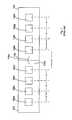
- FIG. 1illustrates two conventional LED strips 105 and 106 that could be used in such a light fixture.
- Each strip 105 , 106includes multiple LED's 108 .
- a second end 105 b of strip 105is electrically and mechanically coupled to a first end 106 a of strip 106 via a connector 110 .
- Adjacent pairs of LED's 108 a - 108 d on strip 105are spaced apart from one another by a distance X.
- Adjacent pairs of LED's 108 e - 108 h on strip 106are spaced apart from one another by the same distance X.
- Adjacent LED's 108 d and 108 e across the LED strips 105 and 106are spaced apart from one another by a distance Y.
- the distance Yis significantly larger than the distance X.
- This space between the LED's 108 d and 108 ecauses the light output by the LED strips 105 and 106 to be discontinuous.
- the light output by the LED strips 105 and 106includes an undesirable break or shadow that corresponds to the space between the LED strips 105 and 106 .
- the inventionprovides an improved linear LED light fixture.
- the inventionprovides LED modules that interface with one another in a variety of different configurations to provide a substantially continuous array of LED's across the LED modules. This continuity in the array of the LED's enables the LED modules to output continuous light across the LED modules, without any undesirable shadows or breaks.
- Each LED moduleincludes a substrate on which one or more LED's are disposed.
- the LED modulescan interface with one another in a substantially continuous, end-to-end relationship.
- each substratecan include a notch or protrusion in which a corresponding protrusion or notch of an adjacent substrate may be disposed.
- adjacent LED modulesinterface with one another, there is a substantially continuous array of LED's across the LED modules.
- one or more rows or patterns of LED'smay continue, substantially uninterrupted, within and across the LED modules.
- the LED modulesmay be powered using electrical connectors, which electrically couple together adjacent LED modules.
- Each electrical connectorcan be coupled to its associated LED modules at locations other than the ends at which the LED modules interface with one another.
- the electrical connectorsdo not impact the continuity of light across adjacent LED modules.
- powered surfacessuch as rails and tracks, may power the LED modules.
- the LED modulesmay be coupled to the powered surfaces.
- a light fixturemay include multiple LED modules mounted to a surface.
- the LED modulesmay be removably coupled to the surface using screws, nails, or other fastening devices.
- the light fixturemay be a linear or non-linear light fixture used in residential, commercial, or other lighting applications.
- FIG. 1is a block diagram that illustrates conventional LED strips of a linear light fixture.
- FIG. 2is a top elevational view of an LED assembly, which includes linear LED modules, in accordance with certain exemplary embodiments.
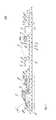
- FIG. 3is a side elevational view of one of the linear LED modules depicted in FIG. 2 , in accordance with certain exemplary embodiments.
- FIG. 4is a top elevational view of an LED assembly, which includes multiple groupings of the linear LED modules depicted in FIG. 2 , in accordance with certain exemplary embodiments.
- FIG. 5is a top elevational view of an LED assembly, which includes LED modules arranged in an “L” shape, in accordance with certain exemplary embodiments.
- FIG. 6is a top elevational view of an LED assembly of linear LED modules, in accordance with certain alternative exemplary embodiments.
- FIG. 7is an elevational bottom view of a light fixture that includes the linear LED modules depicted in FIG. 2 , in accordance with certain exemplary embodiments.
- the inventionis directed to LED modules that interface with one another in a variety of different configurations to provide a substantially continuous array of LED's across the LED modules. This continuity in the array of the LED's enables the LED modules to output continuous light across the LED modules, without any undesirable shadows or breaks.
- the LED modulescan provide light in any of a number of different residential and commercial lighting applications. For example, the LED modules can be installed on any surface to provide cabinet lighting, shelf lighting, cove lighting, and signage.
- FIG. 2is a top elevational view of an LED assembly 290 , which includes LED modules 200 , in accordance with certain exemplary embodiments.
- FIG. 3is a side elevational view of one of the LED modules 200 , in accordance with certain exemplary embodiments.
- each LED module 200is configured to create artificial light or illumination via multiple LED's 205 .
- each LED 205may be a single LED die or may be an LED package having one or more LED dies on the package.
- the number of dies on each LED packageranges from 1-312.
- each LED packagemay include 2 dies.
- Each LED module 200includes at least one substrate 207 to which the LED's 205 are coupled.
- Each substrate 207includes one or more sheets of ceramic, metal, laminate, circuit board, flame retardant (FR) board, mylar, or other material. Although depicted in FIGS. 2 and 3 as having a substantially rectangular shape, a person of ordinary skill in the art having the benefit of the present disclosure will recognize that the substrate 207 can have any linear or non-linear shape.
- Each LED 205is attached to its respective substrate 207 by a solder joint, a plug, an epoxy or bonding line, or other suitable provision for mounting an electrical/optical device on a surface.
- Each LED 205includes semi-conductive material that is treated to create a positive-negative (p-n) junction. When the LED's 205 are electrically coupled to a power source 220 , such as a driver, current flows from the positive side to the negative side of each junction, causing charge carriers to release energy in the form of incoherent light.
- a power source 220
- the wavelength or color of the emitted lightdepends on the materials used to make each LED 205 .
- a blue or ultraviolet LEDtypically includes gallium nitride (GaN) or indium gallium nitride (InGaN)
- a red LEDtypically includes aluminum gallium arsenide (AlGaAs)
- a green LEDtypically includes aluminum gallium phosphide (AlGaP).
- Each of the LED's 205is capable of being configured to produce the same or a distinct color of light.
- the LED's 205include one or more white LED's and one or more non-white LED's, such as red, yellow, amber, green, or blue LED's, for adjusting the color temperature output of the light emitted from the LED modules 200 .
- a yellow or multi-chromatic phosphormay coat or otherwise be used in a blue or ultraviolet LED 205 to create blue and red-shifted light that essentially matches blackbody radiation.
- the emitted lightapproximates or emulates “white,” light to a human observer.
- the emitted lightincludes substantially white light that seems slightly blue, green, red, yellow, orange, or some other color or tint.
- the light emitted from the LED's 205has a color temperature between 2500 and 6000 degrees Kelvin.
- an optically transmissive or clear material(not shown) encapsulates at least some of the LED's 205 , either individually or collectively.
- This encapsulating materialprovides environmental protection while transmitting light from the LED's 205 .
- the encapsulating materialcan include a conformal coating, a silicone gel, a cured/curable polymer, an adhesive, or some other material known to a person of ordinary skill in the art having the benefit of the present disclosure.
- phosphorsare coated onto or dispersed in the encapsulating material for creating white light.
- Each LED module 200includes one or more rows of LED's 205 .
- the term “row”is used herein to refer to an arrangement or a configuration whereby one or more LED's 205 are disposed approximately in or along a line. LED's 205 in a row are not necessarily in perfect alignment with one another. For example, one or more LED's 205 in a row might be slightly out of perfect alignment due to manufacturing tolerances or assembly deviations. In addition, LED's 205 in a row might be purposely staggered in a non-linear or non-continuous arrangement. Each row extends along a longitudinal axis of the LED module 200 .
- each row and/or each LED 205is separately controlled by the driver so that each row can independently be turned on and off or otherwise reconfigured.
- each LED module 200includes 16 LED's 205 .
- the number of LED's 205 on each LED module 200may vary depending on the size of the LED module 200 , the size of the LED's 205 , the amount of illumination required from the LED module 200 , and/or other factors. For example, a larger LED module 200 with small LED's 205 may include more LED's 205 than a smaller LED module 200 with large LED's 205 .
- Adjacent pairs of LED's 205 on each LED module 200are spaced apart from one another by a distance Z.
- Adjacent LED's 205 p and 205 q across LED modules 200 A and 200 Bare spaced apart from one another by the same or substantially the same distance Z.
- adjacent LED's 205 r and 205 s across LED modules 200 B and 200 Care spaced apart from one another by the same or substantially the same distance Z.
- all adjacent pairs of LED's 205 across the LED modules 200are spaced apart by the same or substantially the same distance Z.
- This equal or substantially equal spacing across the LED modules 200provides a continuous array of LED's 205 across the LED modules 200 . Because the array is continuous, light output from the LED modules 200 is continuous, without any undesirable breaks or shadows.
- the LED modules 200can be configured to provide a substantially continuous array of LED's 205 without each adjacent pair of LED's 205 being equally spaced apart.
- Ends 210 and 211 of each LED module 200have profiles that enable adjacent pairs of the LED modules 200 to interface with one another.
- a first side end 210 of each LED module 200includes a protrusion 210 a that is sized and configured to be at least partially disposed adjacent a corresponding notch 211 a in a second side end 211 of an adjacent LED module 200 .
- the second side end 211 of each LED module 200includes a protrusion 211 b that is sized and configured to be at least partially disposed adjacent a corresponding notch 210 b in the first side end 210 of an adjacent LED module 200 .
- the notches 210 b and 211 a and protrusions 210 a and 211 b in the LED modules 200can have any size or shape.
- adjacent LED modules 200may interface one another in other configurations.
- LED modules 200 B and 200 Cmay be arranged such that the protrusion 210 a of LED module 200 C rests at least partially adjacent the notch 211 a or protrusion 211 b of LED module B and a longitudinal axis of LED module 200 C is disposed substantially perpendicular to a longitudinal axis of LED module 200 B, substantially as described below with reference to FIG. 5 .
- the end of one LED module 200can include multiple protrusions that are sized and configured to be disposed within corresponding notches in an adjacent LED module 200 .
- one or both of the ends of each LED module 200may have a substantially flat edge with not notches or protrusions.
- only one of the ends 210 and 211 of each LED module 200may have a profile that enables the LED module 200 to interface with another LED module 200 .
- a top side end 212 of each LED module 200includes one or more protrusions 212 a and notches 212 b sized and configured to engage one or more of the notches 210 b and 211 a and protrusions 210 a and 211 b in the side ends 210 and 211 of another, adjacent LED module 200 .
- adjacent LED modules 200are electrically coupled to one another via a connector 225 a or 225 b .
- Each connector 225 a , 225 bcan include one or more electrical wires, plugs, sockets, and/or other components that enable electrical transmission between electrical devices.
- each connector 225 a , 225 bincludes a first end 226 that is coupled to a protrusion 212 a in a top side end 212 of one LED module 200 and a second end 227 that is coupled to a protrusion 212 a in a top side end 212 of an adjacent LED module 200 .
- each connector 225 a , 225 bmay be coupled to its corresponding LED modules 200 at other locations.
- one or more of the connectors 225 a , 225 bcan be connected to a bottom end 213 of an LED module 200 .
- the LED modules 200can be mounted to a powered rail, track, or other device, which powers the LED modules 200 without using any connectors 225 a , 225 b.
- Each LED module 200is configured to be mounted to a surface (not shown) to illuminate an environment associated with the surface.
- each LED module 200may be mounted to, or within, a wall, counter, cabinet, sign, light fixture, or other surface.
- Each LED module 200may be mounted to its respective surface using solder, braze, welds, glue, epoxy, rivets, clamps, screws, nails, or other fastening means known to a person of ordinary skill in the art having the benefit of the present disclosure.
- one or more of the LED modules 200are removably mounted to their corresponding surfaces to enable efficient repair, replacement, and/or reconfiguration of the LED module(s) 200 .
- each LED module 200may be removably mounted to its corresponding surface via one or more screws extending through openings 215 a defined in protrusions 215 in the top side end 212 of the LED module 200 .
- a personcan simply disconnect the connector(s) 225 a or 225 b associated with the LED module 200 and unscrew the screws associated with the LED module 200 .
- the remaining LED modules 200may be electrically coupled to one another using one or more of the disconnected connectors 225 a or 225 b . For example, if a person removes LED module 200 B, he can electrically couple LED module 200 A to LED module 200 C by connecting the connector 225 a to the LED module 200 C in place of the connector 225 b.
- the level of light a typical LED 205 outputsdepends, in part, upon the amount of electrical current supplied to the LED 205 and upon the operating temperature of the LED 205 .
- the intensity of light emitted by an LED 205changes when electrical current is constant and the LED's 205 temperature varies or when electrical current varies and temperature remains constant, with all other things being equal.
- Operating temperaturealso impacts the usable lifetime of most LED's 205 .
- each LED module 200is configured to manage heat output by its LED's 205 .
- each LED module 200includes a conductive member 305 that is coupled to the substrate 207 and assists in dissipating heat generated by the LED's 205 .
- the member 305acts as a heat sink for the LED's 205 .
- the member 305receives heat conducted from the LED's 205 through the substrate 207 and transfers the conducted heat to the surrounding environment (typically air) via convection.
- FIG. 4is a top elevational view of an LED assembly 400 , which includes multiple groupings of the LED modules 200 depicted in FIG. 2 , in accordance with certain exemplary embodiments.
- interfacesexist at bottom ends 213 of the LED modules 200 .
- a bottom end 213 of each LED module 200engages a bottom end 213 of another, adjacent LED module 200 .
- two adjacent LED modules 200 having a particular widthcan effectively constitute a single, continuous LED source that has a width that is twice the width of a single LED module.
- FIG. 5is a top elevational view of an LED assembly 500 , which includes LED modules 200 arranged in an “L” shape, in accordance with certain exemplary embodiments.
- the LED modules 200provide a flexible and efficient lighting option for both new lighting application installations and retro-fit applications.
- LED modules 200may be arranged on, and secured to, a member to be retro-fit into an existing light fixture.
- FIG. 6is a top elevational view of an LED assembly 600 , which includes linear LED modules 610 A and 610 B, in accordance with certain alternative exemplary embodiments.
- each of the LED modules 610includes one or more rows of LED's 205 .
- the LED's 205 in the LED modules 610 A and 610 Bare not equally spaced apart. Instead, the LED's 205 in the LED modules 610 A and 610 B are arranged in a pattern in which adjacent pairs of LED's 205 have different spacings. In certain exemplary embodiments, the pattern is predictable and repeated on the same LED module 610 .
- the patternmay be repeated continuously across adjacent modules 610 A and 610 B.
- FIG. 7is an elevational bottom view of a light fixture 700 that includes the linear LED modules 200 depicted in FIG. 2 , in accordance with certain exemplary embodiments.
- the light fixture 700includes a troffer 705 that includes a frame 710 having side ends 715 a and 715 b and a top 720 extending between the side ends 715 a and 715 b .
- each side end 715 a and 715 bextends from the top 720 at a substantially orthogonal angle.
- the side ends 715 a and 715 b and top 720define an interior region 725 .
- Rows 730 a and 730 b of LED modules 200extend within the interior region 725 , substantially between the side ends 715 a and 715 b .
- Each LED module 200is mounted to the top 720 via solder, braze, welds, glue, epoxy, rivets, clamps, screws, nails, or other fastening means known to a person of ordinary skill in the art having the benefit of the present disclosure.
- one or more of the LED modules 200are removably mounted to the top 720 to enable efficient repair, replacement, and/or reconfiguration of the LED module(s) 200 .
- each LED module 200may be removably mounted to the top 720 via one or more screws 735 extending through protrusions 215 of each LED module 200 , substantially as described above.
- the LED modules 200are electrically coupled to one another and to a power source (not shown) via one or more wires 740 , substantially as described above.
- the LED fixture 700outputs light from the LED modules 200 into an environment associated with the LED fixture 700 .
- FIG. 7depicts a troffer LED fixture 700
- the LED modules 200may be used in any other light fixture.
- the LED modules 200may be used in light fixtures for indoor and/or outdoor, commercial and/or residential applications.
Landscapes
- Engineering & Computer Science (AREA)
- General Engineering & Computer Science (AREA)
- Non-Portable Lighting Devices Or Systems Thereof (AREA)
- Fastening Of Light Sources Or Lamp Holders (AREA)
- Arrangement Of Elements, Cooling, Sealing, Or The Like Of Lighting Devices (AREA)
Abstract
Description
Claims (19)
Priority Applications (3)
| Application Number | Priority Date | Filing Date | Title |
|---|---|---|---|
| US12/617,127US8308320B2 (en) | 2009-11-12 | 2009-11-12 | Light emitting diode modules with male/female features for end-to-end coupling |
| US13/671,199US8632214B1 (en) | 2009-11-12 | 2012-11-07 | Light modules with uninterrupted arrays of LEDs |
| US14/256,344US9518706B2 (en) | 2009-11-12 | 2014-04-18 | Linear LED light module |
Applications Claiming Priority (1)
| Application Number | Priority Date | Filing Date | Title |
|---|---|---|---|
| US12/617,127US8308320B2 (en) | 2009-11-12 | 2009-11-12 | Light emitting diode modules with male/female features for end-to-end coupling |
Related Child Applications (2)
| Application Number | Title | Priority Date | Filing Date |
|---|---|---|---|
| US13/095,349Continuation-In-PartUS8764220B2 (en) | 2009-11-12 | 2011-04-27 | Linear LED light module |
| US13/671,199ContinuationUS8632214B1 (en) | 2009-11-12 | 2012-11-07 | Light modules with uninterrupted arrays of LEDs |
Publications (2)
| Publication Number | Publication Date |
|---|---|
| US20110110085A1 US20110110085A1 (en) | 2011-05-12 |
| US8308320B2true US8308320B2 (en) | 2012-11-13 |
Family
ID=43974044
Family Applications (2)
| Application Number | Title | Priority Date | Filing Date |
|---|---|---|---|
| US12/617,127Active2030-09-24US8308320B2 (en) | 2009-11-12 | 2009-11-12 | Light emitting diode modules with male/female features for end-to-end coupling |
| US13/671,199ActiveUS8632214B1 (en) | 2009-11-12 | 2012-11-07 | Light modules with uninterrupted arrays of LEDs |
Family Applications After (1)
| Application Number | Title | Priority Date | Filing Date |
|---|---|---|---|
| US13/671,199ActiveUS8632214B1 (en) | 2009-11-12 | 2012-11-07 | Light modules with uninterrupted arrays of LEDs |
Country Status (1)
| Country | Link |
|---|---|
| US (2) | US8308320B2 (en) |
Cited By (6)
| Publication number | Priority date | Publication date | Assignee | Title |
|---|---|---|---|---|
| US20140043802A1 (en)* | 2012-08-10 | 2014-02-13 | Luminaid B.V. | Linear led system |
| EP2957815A1 (en) | 2014-06-17 | 2015-12-23 | Petrus Pfundt | Light fixture with at least one led strip |
| US20160302309A1 (en)* | 2015-04-10 | 2016-10-13 | Osram Gmbh | Support structure for lighting devices and corresponding method |
| US9869435B2 (en) | 2014-04-22 | 2018-01-16 | Cooper Technologies Company | Modular light fixtures |
| US10113718B2 (en) | 2014-04-23 | 2018-10-30 | General Led Opco, Llc | Retrofit system and method for replacing linear fluorescent lamp with LED modules |
| US11672067B2 (en) | 2021-01-29 | 2023-06-06 | Snap-On Incorporated | Circuit board with sensor controlled lights and end-to-end connection |
Families Citing this family (27)
| Publication number | Priority date | Publication date | Assignee | Title |
|---|---|---|---|---|
| US9395057B2 (en)* | 2011-02-07 | 2016-07-19 | Cree, Inc. | Lighting device with flexibly coupled heatsinks |
| JP5463478B2 (en)* | 2011-03-04 | 2014-04-09 | シーシーエス株式会社 | Line light irradiation device |
| US9170010B2 (en) | 2011-07-27 | 2015-10-27 | American Dj Supply, Inc. | DMX controllable low profile lighting apparatus |
| US20130122724A1 (en)* | 2011-11-14 | 2013-05-16 | American Dj Supply, Inc. | Connectable lighting apparatus |
| US9519095B2 (en) | 2013-01-30 | 2016-12-13 | Cree, Inc. | Optical waveguides |
| US9625638B2 (en) | 2013-03-15 | 2017-04-18 | Cree, Inc. | Optical waveguide body |
| US9366396B2 (en) | 2013-01-30 | 2016-06-14 | Cree, Inc. | Optical waveguide and lamp including same |
| US9690029B2 (en) | 2013-01-30 | 2017-06-27 | Cree, Inc. | Optical waveguides and luminaires incorporating same |
| US9291320B2 (en) | 2013-01-30 | 2016-03-22 | Cree, Inc. | Consolidated troffer |
| US9869432B2 (en) | 2013-01-30 | 2018-01-16 | Cree, Inc. | Luminaires using waveguide bodies and optical elements |
| US9442243B2 (en) | 2013-01-30 | 2016-09-13 | Cree, Inc. | Waveguide bodies including redirection features and methods of producing same |
| US9366799B2 (en) | 2013-03-15 | 2016-06-14 | Cree, Inc. | Optical waveguide bodies and luminaires utilizing same |
| US10436970B2 (en) | 2013-03-15 | 2019-10-08 | Ideal Industries Lighting Llc | Shaped optical waveguide bodies |
| US10502899B2 (en)* | 2013-03-15 | 2019-12-10 | Ideal Industries Lighting Llc | Outdoor and/or enclosed structure LED luminaire |
| US10379278B2 (en)* | 2013-03-15 | 2019-08-13 | Ideal Industries Lighting Llc | Outdoor and/or enclosed structure LED luminaire outdoor and/or enclosed structure LED luminaire having outward illumination |
| US10400984B2 (en) | 2013-03-15 | 2019-09-03 | Cree, Inc. | LED light fixture and unitary optic member therefor |
| US10209429B2 (en) | 2013-03-15 | 2019-02-19 | Cree, Inc. | Luminaire with selectable luminous intensity pattern |
| US9920901B2 (en) | 2013-03-15 | 2018-03-20 | Cree, Inc. | LED lensing arrangement |
| US9798072B2 (en) | 2013-03-15 | 2017-10-24 | Cree, Inc. | Optical element and method of forming an optical element |
| US20140331532A1 (en)* | 2013-05-08 | 2014-11-13 | Almax Manufacturing Corporation | Flexible clear and transparent lighting strips and signage |
| US20150116997A1 (en)* | 2013-10-29 | 2015-04-30 | Acrooptics, Llc | LED Lighting System for Promoting Biological Growth |
| US10069042B2 (en)* | 2014-11-19 | 2018-09-04 | Panasonic Intellectual Property Management Co., Ltd. | Light-emitting components containing body, manufacturing method of light-emitting components containing body, components mounting apparatus, components mounting method, and components mounting system |
| CA2982239C (en) | 2015-04-13 | 2024-05-07 | Hubbell Incorporated | Light board |
| US10253956B2 (en) | 2015-08-26 | 2019-04-09 | Abl Ip Holding Llc | LED luminaire with mounting structure for LED circuit board |
| US10416377B2 (en) | 2016-05-06 | 2019-09-17 | Cree, Inc. | Luminaire with controllable light emission |
| US11719882B2 (en) | 2016-05-06 | 2023-08-08 | Ideal Industries Lighting Llc | Waveguide-based light sources with dynamic beam shaping |
| US10251279B1 (en) | 2018-01-04 | 2019-04-02 | Abl Ip Holding Llc | Printed circuit board mounting with tabs |
Citations (147)
| Publication number | Priority date | Publication date | Assignee | Title |
|---|---|---|---|---|
| US3038139A (en) | 1958-06-13 | 1962-06-05 | Lionel Corp | Magnetic socket device |
| US3706882A (en) | 1971-02-23 | 1972-12-19 | George W Eby | Emergency signal light with magnetic contacts |
| US3810258A (en) | 1972-07-11 | 1974-05-07 | W Mathauser | Quick connect electrical coupler |
| US4302800A (en)* | 1978-10-10 | 1981-11-24 | Pelletier Jean F S | Lamp means with orientable modular elements |
| US4538214A (en) | 1983-12-29 | 1985-08-27 | American Sterilizer Company | Magnetically supported surgical light |
| US4617612A (en) | 1985-01-22 | 1986-10-14 | Pritchett John C | High efficiency task lighting fixture |
| US4667277A (en)* | 1985-09-20 | 1987-05-19 | General Instrument Corporation | Indicator lamp assembly |
| US4719549A (en) | 1984-12-24 | 1988-01-12 | Apel Volker H P | Connection between two mechanically and electrically releasably coupled parts, in particular for use with an illumination system |
| US4752756A (en) | 1986-03-21 | 1988-06-21 | Bernhard Bartel | Electrical system with at least one electric load unit being disconnectably arranged on a surface |
| US4959761A (en) | 1989-12-21 | 1990-09-25 | Dialight Corporation | Surface mounted led package |
| US5154509A (en) | 1992-01-15 | 1992-10-13 | 291, Inc. | Low voltage magnetic track light system |
| US5161882A (en)* | 1991-08-15 | 1992-11-10 | Garrett Joe L | Christmas lighting organizer apparatus |
| US5291039A (en) | 1991-09-30 | 1994-03-01 | Rohm Co., Ltd. | LED head having heat radiating mount |
| US5342204A (en) | 1988-09-19 | 1994-08-30 | Herma Ag | Low voltage busbar lighting apparatus |
| US5397239A (en) | 1993-12-17 | 1995-03-14 | Circuit-Wise, Inc. | Molded hinged connector |
| US5418384A (en) | 1992-03-11 | 1995-05-23 | Sharp Kabushiki Kaisha | Light-source device including a linear array of LEDs |
| US5559681A (en)* | 1994-05-13 | 1996-09-24 | Cnc Automation, Inc. | Flexible, self-adhesive, modular lighting system |
| US5660461A (en)* | 1994-12-08 | 1997-08-26 | Quantum Devices, Inc. | Arrays of optoelectronic devices and method of making same |
| US6050044A (en)* | 1998-07-27 | 2000-04-18 | Kitsilano Industries Inc. | Building block |
| US6176760B1 (en)* | 1999-07-26 | 2001-01-23 | Artin Industrial Co., Ltd. | Toy racing car track bridge |
| US6233971B1 (en) | 1998-08-14 | 2001-05-22 | Calypso Worldwide Marketing, Inc. | Jewelry piece |
| US6320182B1 (en) | 1999-11-30 | 2001-11-20 | Xerox Corporation | Light collector for an LED array |
| US6343942B1 (en) | 1998-10-26 | 2002-02-05 | Sumitomo Wiring Systems, Ltd. | Connection configuration of a multiple-light lighting fixture |
| US6357904B1 (en) | 1999-04-19 | 2002-03-19 | Nec Corporation | Linear illumination device |
| US6361186B1 (en) | 2000-08-02 | 2002-03-26 | Lektron Industrial Supply, Inc. | Simulated neon light using led's |
| US6367948B2 (en) | 2000-05-15 | 2002-04-09 | William A. Branson | Illuminated basketball backboard |
| US20020093832A1 (en) | 2000-07-17 | 2002-07-18 | Hamilton Alan James | Luminair |
| US6422716B2 (en) | 2000-03-16 | 2002-07-23 | Bjb Gmbh & Co. Kg | Modular led assembly |
| US6426807B1 (en) | 1993-01-19 | 2002-07-30 | Canon Kabushiki Kaisha | Light guide, illuminating device having the light guide, and image reading device and information processing apparatus having the illuminating device |
| US6509840B2 (en) | 2001-01-10 | 2003-01-21 | Gelcore Llc | Sun phantom led traffic signal |
| US20030048641A1 (en) | 2001-09-13 | 2003-03-13 | Alexanderson James Kenneth | LED lighting device and system |
| US6540372B2 (en) | 2000-07-31 | 2003-04-01 | Lites Now, Llc | Electrical track lighting system |
| US20030081419A1 (en) | 2001-10-25 | 2003-05-01 | Jacob Stephane Frederick | Solid state continuous sealed clean room light fixture |
| US6561690B2 (en) | 2000-08-22 | 2003-05-13 | Koninklijke Philips Electronics N.V. | Luminaire based on the light emission of light-emitting diodes |
| US6582100B1 (en) | 2000-08-09 | 2003-06-24 | Relume Corporation | LED mounting system |
| US6585393B1 (en) | 1998-10-09 | 2003-07-01 | Satco Products, Inc. | Modular accent light fixture |
| US6592238B2 (en) | 2001-01-31 | 2003-07-15 | Light Technologies, Inc. | Illumination device for simulation of neon lighting |
| US6601970B2 (en) | 2000-07-14 | 2003-08-05 | Kyoto Denkiki Co., Ltd. | Linear lighting system |
| US6612717B2 (en)* | 2001-06-21 | 2003-09-02 | George Yen | High efficient tubular light emitting cylinder |
| US20030174517A1 (en) | 2002-03-18 | 2003-09-18 | Chris Kiraly | Extensible linear light emitting diode illumination source |
| US6641284B2 (en) | 2002-02-21 | 2003-11-04 | Whelen Engineering Company, Inc. | LED light assembly |
| US6641294B2 (en)* | 2002-03-22 | 2003-11-04 | Emteq, Inc. | Vehicle lighting assembly with stepped dimming |
| US20030223235A1 (en) | 2002-06-03 | 2003-12-04 | Ferenc Mohacsi | LED accent lighting units |
| US6659622B2 (en) | 2000-11-24 | 2003-12-09 | Moriyama Sangyo Kabushiki Kaisha | Illumination system and illumination unit |
| US6676284B1 (en) | 1998-09-04 | 2004-01-13 | Wynne Willson Gottelier Limited | Apparatus and method for providing a linear effect |
| US20040076004A1 (en) | 2002-10-22 | 2004-04-22 | Smith John L. | Lamp apparatus, lamp and optical lens assembly and lamp housing assembly |
| US20040114355A1 (en) | 2001-05-30 | 2004-06-17 | Alexander Rizkin | In-pavement directional LED luminaire |
| US6761472B1 (en) | 2001-10-18 | 2004-07-13 | Ilight Technologies, Inc. | Water submergible simulated neon lighting device |
| US6767111B1 (en) | 2003-02-26 | 2004-07-27 | Kuo-Yen Lai | Projection light source from light emitting diodes |
| US6776504B2 (en) | 2001-07-25 | 2004-08-17 | Thomas C. Sloan | Perimeter lighting apparatus |
| US20040161213A1 (en) | 2003-02-15 | 2004-08-19 | Tsung-Ting Lee | Fiber optic display device |
| US6802626B2 (en) | 2002-05-31 | 2004-10-12 | Lighting World Inc. | Track lighting system including lamp clips with separate locking and connection means |
| US20040201980A1 (en) | 2003-04-11 | 2004-10-14 | Ultradent Products, Inc. | Illumination apparatus for enhancing visibility of oral tissues |
| US6882111B2 (en)* | 2003-07-09 | 2005-04-19 | Tir Systems Ltd. | Strip lighting system incorporating light emitting devices |
| US20050146899A1 (en) | 2001-07-31 | 2005-07-07 | Litesnow Llc | Electrical lighting systems |
| US20050157500A1 (en) | 2004-01-21 | 2005-07-21 | Wen-Ho Chen | Illumination apparatus with laser emitting diode |
| US20050162265A1 (en) | 2003-10-27 | 2005-07-28 | Werner David R. | Auxiliary safety light system |
| US6932495B2 (en)* | 2001-10-01 | 2005-08-23 | Sloanled, Inc. | Channel letter lighting using light emitting diodes |
| US6940659B2 (en) | 2002-01-11 | 2005-09-06 | Ultradent Products, Inc. | Cone-shaped lens having increased forward light intensity and kits incorporating such lenses |
| US20050264473A1 (en) | 2004-04-29 | 2005-12-01 | Sibbett Gary M | Modular lighted display and method therefor |
| US20060093308A1 (en) | 2003-06-12 | 2006-05-04 | Ryan Patrick H Jr | Light emitting module |
| US7066739B2 (en) | 2002-07-16 | 2006-06-27 | Mcleish Graham John | Connector |
| US7070418B1 (en) | 2005-05-26 | 2006-07-04 | Keeper Technology Co., Ltd. | Light emitting diode assembly |
| US20060146531A1 (en) | 2004-12-30 | 2006-07-06 | Ann Reo | Linear lighting apparatus with improved heat dissipation |
| US7101056B2 (en) | 2002-12-04 | 2006-09-05 | Gelcore Llc | Illuminated LED street sign |
| US7137727B2 (en) | 2000-07-31 | 2006-11-21 | Litesnow Llc | Electrical track lighting system |
| US20060262533A1 (en) | 2005-05-18 | 2006-11-23 | Para Light Electronics Co., Ltd. | Modular light emitting diode |
| US7159997B2 (en) | 2004-12-30 | 2007-01-09 | Lo Lighting | Linear lighting apparatus with increased light-transmission efficiency |
| US7161189B2 (en) | 2004-06-04 | 2007-01-09 | Lite-On Technology Corporation | LED package including a frame |
| US7163404B2 (en) | 2002-08-07 | 2007-01-16 | Koninklijke Philips Electronics, N.V. | Device for placing a lamp in a reflector |
| US7201511B2 (en) | 2002-10-25 | 2007-04-10 | Moriyama Sangyo Kabushiki Kaisha | Light emitting module |
| US7213941B2 (en) | 2004-04-14 | 2007-05-08 | Sloanled, Inc. | Flexible perimeter lighting apparatus |
| US20070147030A1 (en) | 2003-09-18 | 2007-06-28 | Samsung Electronics Co., Ltd | Backlight assembly and display device having the same |
| US7241031B2 (en) | 2004-04-14 | 2007-07-10 | Sloanled, Inc. | Channel letter lighting system using high output white light emitting diodes |
| US20070190845A1 (en) | 2004-04-06 | 2007-08-16 | Gelcore Llc | Flexible high-power led lighting system |
| US7273299B2 (en) | 2005-01-26 | 2007-09-25 | Pelka & Associates | Cylindrical irradiance-mapping lens and its applications to LED shelf-lighting |
| US7290913B2 (en) | 2004-08-24 | 2007-11-06 | Koito Manufacturing Co., Ltd. | Light emitting module and lighting unit |
| US7322828B1 (en) | 2007-04-16 | 2008-01-29 | Chiang Wen Chiang | LED socket |
| US7322873B2 (en)* | 2004-10-19 | 2008-01-29 | Mega Brands America, Inc. | Illuminated, three-dimensional modules with coaxial magnetic connectors for a toy construction kit |
| US7322718B2 (en) | 2003-01-27 | 2008-01-29 | Matsushita Electric Industrial Co., Ltd. | Multichip LED lighting device |
| US20080030981A1 (en)* | 2004-08-06 | 2008-02-07 | Matthew Mrakovich | Elongated Led Illumination Device |
| US7348604B2 (en) | 2005-05-20 | 2008-03-25 | Tir Technology Lp | Light-emitting module |
| US7350937B2 (en)* | 2004-05-25 | 2008-04-01 | Hitachi Displays, Ltd. | Lighting unit, lighting module, and liquid crystal display |
| US20080094828A1 (en)* | 2006-10-24 | 2008-04-24 | Shu-Fa Shao | Light-emitting diode lamp bank |
| US7377669B2 (en)* | 2005-03-28 | 2008-05-27 | U.S. Led, Ltd. | LED module and system of LED modules with integral branch connectors |
| US7384170B2 (en) | 2003-12-30 | 2008-06-10 | Troy-Csl Lighting, Inc. | Counter light fixture |
| US20080158878A1 (en) | 2006-12-18 | 2008-07-03 | Peter Van Laanen | Flow-Through LED Lighting System |
| US20080170367A1 (en) | 2007-01-12 | 2008-07-17 | Tai-Sol Electronics Co., Ltd. | Combination assembly of LED and liquid-vapor thermally dissipating device |
| US7401946B2 (en)* | 2004-07-07 | 2008-07-22 | Pent Technologies, Inc. | Modular wiring for linear lighting |
| US20080244944A1 (en) | 2006-10-05 | 2008-10-09 | Lumination, Llc | LED backlighting system for cabinet sign |
| US20080298058A1 (en) | 2005-05-20 | 2008-12-04 | Tir Systems Ltd. | Cove Illumination Module and System |
| US7470055B2 (en) | 2005-08-29 | 2008-12-30 | Patent-Treuhand-Gesellschaft Fur Elektrische Gluhlampen Mbh | Mounting structure for LED lighting systems |
| US7478920B2 (en) | 2005-11-29 | 2009-01-20 | Sharp Kabushiki Kaisha | Backlight and liquid crystal display device |
| US20090021936A1 (en) | 2007-07-19 | 2009-01-22 | Lumination Llc | Linear led illumination system |
| US20090073693A1 (en) | 2007-09-17 | 2009-03-19 | Nall Jeffrey M | Led lighting system for a cabinet sign |
| US7506995B2 (en) | 2004-09-23 | 2009-03-24 | Priscilla G. Thomas | Illumination system for use with display signage |
| US20090101921A1 (en) | 2007-10-17 | 2009-04-23 | Tai-Sol Electronics Co., Ltd. | LED and thermal conductivity device combination assembly |
| US7538356B2 (en) | 2006-11-22 | 2009-05-26 | Tai-Sol Electronics Co., Ltd | Combination assembly of LED and liquid-vapor thermally dissipating device |
| US7549779B2 (en) | 2007-02-16 | 2009-06-23 | Shawn Michael Genenbacher | Magnetic light fixture |
| US20090161371A1 (en) | 2005-09-01 | 2009-06-25 | Vukosic Stephen T | Light emitter sub-assemblies especially containing an array of light emitting devices (LEDs) and modules containing such sub-assemblies which provide lighting apparatuses, especially light bars for mounting on a vehicle |
| US7572027B2 (en) | 2005-09-15 | 2009-08-11 | Integrated Illumination Systems, Inc. | Interconnection arrangement having mortise and tenon connection features |
| US20090224265A1 (en) | 2008-03-05 | 2009-09-10 | Bily Wang | LED chip package structure with a high-efficiency heat-dissipating substrate and method for making the same |
| US20090237011A1 (en) | 2008-03-20 | 2009-09-24 | Ashok Deepak Shah | Illumination Device and Fixture |
| US20090279298A1 (en) | 2008-05-06 | 2009-11-12 | Koninklijke Philips Electronics, N.V | Movable led track luminaire |
| US20090290348A1 (en) | 2006-04-16 | 2009-11-26 | Peter Van Laanen | Thermal Management Of LED-Based Lighting Systems |
| US7625104B2 (en) | 2007-12-13 | 2009-12-01 | Philips Lumileds Lighting Company, Llc | Light emitting diode for mounting to a heat sink |
| US20090303712A1 (en) | 2008-06-06 | 2009-12-10 | Fu Zhun Precision Industry (Shen Zhen) Co., Ltd. | Led lamp |
| US20090310335A1 (en) | 2007-04-16 | 2009-12-17 | Lg Innotek Co., Ltd | Light source device and display device having the same |
| US20100002450A1 (en) | 2007-02-14 | 2010-01-07 | Ledon Lighting Jennersdorf Gmbh | Mounting Lenses for LED Modules |
| US20100053956A1 (en) | 2008-09-01 | 2010-03-04 | Samsung Electro-Mechanics Co., Ltd. | Light emitting module |
| US7677914B2 (en) | 2005-07-13 | 2010-03-16 | Lumination Llc | LED string light engine and devices that are illuminated by the string light engine |
| US20100073931A1 (en) | 2008-09-22 | 2010-03-25 | Toshiba Lighting & Technology Corporation | Light-emitting module, light-emitting device having the light-emitting module, and lighting apparatus having the light-emitting device |
| US7703941B2 (en)* | 2008-04-29 | 2010-04-27 | Lee Ching Chuan | Expandable LED module for arbitrarily display assembly |
| US20100103687A1 (en) | 2007-01-30 | 2010-04-29 | Accessmount Llc | Track lighting assembly employing interim assembly between track and track head |
| US20100103672A1 (en) | 2006-06-30 | 2010-04-29 | James Thomas | Low-profile elongated LED light fixture |
| US20100110680A1 (en) | 2008-10-31 | 2010-05-06 | Osram Gesellschaft Mit Beschraenkter Haftung | Mounting arrangement for lighting modules and corresponding method |
| US20100118532A1 (en) | 2008-11-10 | 2010-05-13 | Everlight Electronics Co., Ltd. | Illumination device and light emitting diode module |
| US20100124067A1 (en) | 2007-02-12 | 2010-05-20 | Koninklijke Philips Electronics N.V. | Control module for a lighting system, lighting system and light module for a lighting system |
| US7726840B2 (en)* | 2008-03-04 | 2010-06-01 | Tempo Industries, Inc. | Modular LED lighting fixtures |
| US20100135022A1 (en) | 2003-05-01 | 2010-06-03 | Kevin Raymond Deguara | Lighting substrate |
| US7731558B2 (en)* | 2007-08-15 | 2010-06-08 | Jon Capriola | Illuminated toy building structures |
| US20100164409A1 (en) | 2006-09-12 | 2010-07-01 | Paul Lo | Integrally formed light emitting diode light wire and uses thereof |
| US20100182782A1 (en) | 2009-01-21 | 2010-07-22 | Cooper Technologies Company | Light Emitting Diode Troffer |
| US20100182788A1 (en) | 2009-01-19 | 2010-07-22 | Osram Sylvania Inc. | Led lamp assembly |
| US20100188846A1 (en) | 2009-01-29 | 2010-07-29 | Yamagata Promotional Organization For Industrial Technology | Illuminating device |
| US20100195322A1 (en) | 2007-07-30 | 2010-08-05 | Sharp Kabushiki Kaisha | Light emitting device, illuminating apparatus and clean room equipped with illuminating apparatus |
| US20100201269A1 (en) | 2009-02-12 | 2010-08-12 | Hua-Lung Tzou | Separate LED Lamp Tube and Light Source Module Formed Therefrom |
| US20100214747A1 (en) | 2007-02-12 | 2010-08-26 | Koninklijke Philips Electronics N.V. | Modular electric system |
| US20100214779A1 (en)* | 2009-02-23 | 2010-08-26 | Ying-Feng Kao | LED Fluorescent Tube |
| US20100220479A1 (en)* | 2009-02-27 | 2010-09-02 | Atsushi Yamashita | Led module and led light source apparatus |
| US7791089B2 (en) | 2008-08-26 | 2010-09-07 | Albeo Technologies, Inc. | LED packaging methods and LED-based lighting products |
| US7789529B2 (en) | 2005-11-18 | 2010-09-07 | Cree, Inc. | LED lighting units and assemblies with edge connectors |
| US20100226125A1 (en) | 2009-03-04 | 2010-09-09 | Chunghwa Picture Tubes, Ltd. | Lamp shade |
| US20100232154A1 (en) | 2009-03-11 | 2010-09-16 | Chung-Yu Chen | Fluorescent tube |
| US7806574B2 (en) | 2006-04-16 | 2010-10-05 | Albeo Technologies, Inc. | Thermal management of LED-based lighting systems |
| US7806569B2 (en) | 2007-09-28 | 2010-10-05 | Osram Sylvania Inc. | Lighting system with removable light modules |
| US20100254134A1 (en)* | 2009-04-02 | 2010-10-07 | Mccanless Forrest S | Light Fixture |
| US7815341B2 (en) | 2007-02-14 | 2010-10-19 | Permlight Products, Inc. | Strip illumination device |
| US20100271834A1 (en) | 2009-04-23 | 2010-10-28 | Future Tec (Hong Kong) Limited | Led lighting system |
| US20100271804A1 (en) | 2009-04-22 | 2010-10-28 | Levine Jonathan E | Modular lighting device kit |
| US20100277098A1 (en) | 2009-04-30 | 2010-11-04 | Timothy Sarna | Led lighting system |
| US20100277913A1 (en) | 2007-01-09 | 2010-11-04 | Lucifer Lighting Company | Light Source Mounting System and Method |
| US20100277666A1 (en) | 2007-05-22 | 2010-11-04 | OSRAM Gelsellschaft mit beschrankter | Lighting Device, Backlighting Device, and Display Device |
| US20100308350A1 (en) | 2008-08-26 | 2010-12-09 | Jeffrey Bisberg | LED Chip-Based Lighting Products And Methods Of Building |
| US7857482B2 (en) | 2004-12-30 | 2010-12-28 | Cooper Technologies Company | Linear lighting apparatus with increased light-transmission efficiency |
| US20110013377A1 (en)* | 2007-09-11 | 2011-01-20 | Kim Deung Kwan | Light unit and display apparatus having the same |
| US8052299B2 (en)* | 2008-12-05 | 2011-11-08 | Hon Hai Precision Industry Co., Ltd. | Light source module and light source module array having same |
- 2009
- 2009-11-12USUS12/617,127patent/US8308320B2/enactiveActive
- 2012
- 2012-11-07USUS13/671,199patent/US8632214B1/enactiveActive
Patent Citations (153)
| Publication number | Priority date | Publication date | Assignee | Title |
|---|---|---|---|---|
| US3038139A (en) | 1958-06-13 | 1962-06-05 | Lionel Corp | Magnetic socket device |
| US3706882A (en) | 1971-02-23 | 1972-12-19 | George W Eby | Emergency signal light with magnetic contacts |
| US3810258A (en) | 1972-07-11 | 1974-05-07 | W Mathauser | Quick connect electrical coupler |
| US4302800A (en)* | 1978-10-10 | 1981-11-24 | Pelletier Jean F S | Lamp means with orientable modular elements |
| US4538214A (en) | 1983-12-29 | 1985-08-27 | American Sterilizer Company | Magnetically supported surgical light |
| US4719549A (en) | 1984-12-24 | 1988-01-12 | Apel Volker H P | Connection between two mechanically and electrically releasably coupled parts, in particular for use with an illumination system |
| US4617612A (en) | 1985-01-22 | 1986-10-14 | Pritchett John C | High efficiency task lighting fixture |
| US4667277A (en)* | 1985-09-20 | 1987-05-19 | General Instrument Corporation | Indicator lamp assembly |
| US4752756A (en) | 1986-03-21 | 1988-06-21 | Bernhard Bartel | Electrical system with at least one electric load unit being disconnectably arranged on a surface |
| US5342204A (en) | 1988-09-19 | 1994-08-30 | Herma Ag | Low voltage busbar lighting apparatus |
| US5397238A (en) | 1988-09-19 | 1995-03-14 | Herma Ag | Low voltage busbar lighting apparatus |
| US4959761A (en) | 1989-12-21 | 1990-09-25 | Dialight Corporation | Surface mounted led package |
| US5161882A (en)* | 1991-08-15 | 1992-11-10 | Garrett Joe L | Christmas lighting organizer apparatus |
| US5291039A (en) | 1991-09-30 | 1994-03-01 | Rohm Co., Ltd. | LED head having heat radiating mount |
| US5154509A (en) | 1992-01-15 | 1992-10-13 | 291, Inc. | Low voltage magnetic track light system |
| US5418384A (en) | 1992-03-11 | 1995-05-23 | Sharp Kabushiki Kaisha | Light-source device including a linear array of LEDs |
| US6426807B1 (en) | 1993-01-19 | 2002-07-30 | Canon Kabushiki Kaisha | Light guide, illuminating device having the light guide, and image reading device and information processing apparatus having the illuminating device |
| US5397239A (en) | 1993-12-17 | 1995-03-14 | Circuit-Wise, Inc. | Molded hinged connector |
| US5559681A (en)* | 1994-05-13 | 1996-09-24 | Cnc Automation, Inc. | Flexible, self-adhesive, modular lighting system |
| US5660461A (en)* | 1994-12-08 | 1997-08-26 | Quantum Devices, Inc. | Arrays of optoelectronic devices and method of making same |
| US6050044A (en)* | 1998-07-27 | 2000-04-18 | Kitsilano Industries Inc. | Building block |
| US6233971B1 (en) | 1998-08-14 | 2001-05-22 | Calypso Worldwide Marketing, Inc. | Jewelry piece |
| US6676284B1 (en) | 1998-09-04 | 2004-01-13 | Wynne Willson Gottelier Limited | Apparatus and method for providing a linear effect |
| US6585393B1 (en) | 1998-10-09 | 2003-07-01 | Satco Products, Inc. | Modular accent light fixture |
| US6343942B1 (en) | 1998-10-26 | 2002-02-05 | Sumitomo Wiring Systems, Ltd. | Connection configuration of a multiple-light lighting fixture |
| US6357904B1 (en) | 1999-04-19 | 2002-03-19 | Nec Corporation | Linear illumination device |
| US6176760B1 (en)* | 1999-07-26 | 2001-01-23 | Artin Industrial Co., Ltd. | Toy racing car track bridge |
| US6320182B1 (en) | 1999-11-30 | 2001-11-20 | Xerox Corporation | Light collector for an LED array |
| US6422716B2 (en) | 2000-03-16 | 2002-07-23 | Bjb Gmbh & Co. Kg | Modular led assembly |
| US6367948B2 (en) | 2000-05-15 | 2002-04-09 | William A. Branson | Illuminated basketball backboard |
| US6601970B2 (en) | 2000-07-14 | 2003-08-05 | Kyoto Denkiki Co., Ltd. | Linear lighting system |
| US20020093832A1 (en) | 2000-07-17 | 2002-07-18 | Hamilton Alan James | Luminair |
| US7137727B2 (en) | 2000-07-31 | 2006-11-21 | Litesnow Llc | Electrical track lighting system |
| US6540372B2 (en) | 2000-07-31 | 2003-04-01 | Lites Now, Llc | Electrical track lighting system |
| US6361186B1 (en) | 2000-08-02 | 2002-03-26 | Lektron Industrial Supply, Inc. | Simulated neon light using led's |
| US6582100B1 (en) | 2000-08-09 | 2003-06-24 | Relume Corporation | LED mounting system |
| US6561690B2 (en) | 2000-08-22 | 2003-05-13 | Koninklijke Philips Electronics N.V. | Luminaire based on the light emission of light-emitting diodes |
| US6659622B2 (en) | 2000-11-24 | 2003-12-09 | Moriyama Sangyo Kabushiki Kaisha | Illumination system and illumination unit |
| US6509840B2 (en) | 2001-01-10 | 2003-01-21 | Gelcore Llc | Sun phantom led traffic signal |
| US6592238B2 (en) | 2001-01-31 | 2003-07-15 | Light Technologies, Inc. | Illumination device for simulation of neon lighting |
| US20040114355A1 (en) | 2001-05-30 | 2004-06-17 | Alexander Rizkin | In-pavement directional LED luminaire |
| US6612717B2 (en)* | 2001-06-21 | 2003-09-02 | George Yen | High efficient tubular light emitting cylinder |
| US6776504B2 (en) | 2001-07-25 | 2004-08-17 | Thomas C. Sloan | Perimeter lighting apparatus |
| US20050146899A1 (en) | 2001-07-31 | 2005-07-07 | Litesnow Llc | Electrical lighting systems |
| US20030048641A1 (en) | 2001-09-13 | 2003-03-13 | Alexanderson James Kenneth | LED lighting device and system |
| US6932495B2 (en)* | 2001-10-01 | 2005-08-23 | Sloanled, Inc. | Channel letter lighting using light emitting diodes |
| US6761472B1 (en) | 2001-10-18 | 2004-07-13 | Ilight Technologies, Inc. | Water submergible simulated neon lighting device |
| US20030081419A1 (en) | 2001-10-25 | 2003-05-01 | Jacob Stephane Frederick | Solid state continuous sealed clean room light fixture |
| US6940659B2 (en) | 2002-01-11 | 2005-09-06 | Ultradent Products, Inc. | Cone-shaped lens having increased forward light intensity and kits incorporating such lenses |
| US6641284B2 (en) | 2002-02-21 | 2003-11-04 | Whelen Engineering Company, Inc. | LED light assembly |
| US20030174517A1 (en) | 2002-03-18 | 2003-09-18 | Chris Kiraly | Extensible linear light emitting diode illumination source |
| US6641294B2 (en)* | 2002-03-22 | 2003-11-04 | Emteq, Inc. | Vehicle lighting assembly with stepped dimming |
| US6802626B2 (en) | 2002-05-31 | 2004-10-12 | Lighting World Inc. | Track lighting system including lamp clips with separate locking and connection means |
| US20030223235A1 (en) | 2002-06-03 | 2003-12-04 | Ferenc Mohacsi | LED accent lighting units |
| US7063440B2 (en) | 2002-06-03 | 2006-06-20 | Everbrite, Llc | LED accent lighting units |
| US7066739B2 (en) | 2002-07-16 | 2006-06-27 | Mcleish Graham John | Connector |
| US7163404B2 (en) | 2002-08-07 | 2007-01-16 | Koninklijke Philips Electronics, N.V. | Device for placing a lamp in a reflector |
| US20040076004A1 (en) | 2002-10-22 | 2004-04-22 | Smith John L. | Lamp apparatus, lamp and optical lens assembly and lamp housing assembly |
| US7201511B2 (en) | 2002-10-25 | 2007-04-10 | Moriyama Sangyo Kabushiki Kaisha | Light emitting module |
| US7101056B2 (en) | 2002-12-04 | 2006-09-05 | Gelcore Llc | Illuminated LED street sign |
| US7322718B2 (en) | 2003-01-27 | 2008-01-29 | Matsushita Electric Industrial Co., Ltd. | Multichip LED lighting device |
| US20040161213A1 (en) | 2003-02-15 | 2004-08-19 | Tsung-Ting Lee | Fiber optic display device |
| US6767111B1 (en) | 2003-02-26 | 2004-07-27 | Kuo-Yen Lai | Projection light source from light emitting diodes |
| US20040201980A1 (en) | 2003-04-11 | 2004-10-14 | Ultradent Products, Inc. | Illumination apparatus for enhancing visibility of oral tissues |
| US20100135022A1 (en) | 2003-05-01 | 2010-06-03 | Kevin Raymond Deguara | Lighting substrate |
| US20060093308A1 (en) | 2003-06-12 | 2006-05-04 | Ryan Patrick H Jr | Light emitting module |
| US6882111B2 (en)* | 2003-07-09 | 2005-04-19 | Tir Systems Ltd. | Strip lighting system incorporating light emitting devices |
| US20070147030A1 (en) | 2003-09-18 | 2007-06-28 | Samsung Electronics Co., Ltd | Backlight assembly and display device having the same |
| US20050162265A1 (en) | 2003-10-27 | 2005-07-28 | Werner David R. | Auxiliary safety light system |
| US7384170B2 (en) | 2003-12-30 | 2008-06-10 | Troy-Csl Lighting, Inc. | Counter light fixture |
| US20050157500A1 (en) | 2004-01-21 | 2005-07-21 | Wen-Ho Chen | Illumination apparatus with laser emitting diode |
| US20070190845A1 (en) | 2004-04-06 | 2007-08-16 | Gelcore Llc | Flexible high-power led lighting system |
| US7241031B2 (en) | 2004-04-14 | 2007-07-10 | Sloanled, Inc. | Channel letter lighting system using high output white light emitting diodes |
| US7213941B2 (en) | 2004-04-14 | 2007-05-08 | Sloanled, Inc. | Flexible perimeter lighting apparatus |
| US20050264473A1 (en) | 2004-04-29 | 2005-12-01 | Sibbett Gary M | Modular lighted display and method therefor |
| US7350937B2 (en)* | 2004-05-25 | 2008-04-01 | Hitachi Displays, Ltd. | Lighting unit, lighting module, and liquid crystal display |
| US7161189B2 (en) | 2004-06-04 | 2007-01-09 | Lite-On Technology Corporation | LED package including a frame |
| US7401946B2 (en)* | 2004-07-07 | 2008-07-22 | Pent Technologies, Inc. | Modular wiring for linear lighting |
| US20080030981A1 (en)* | 2004-08-06 | 2008-02-07 | Matthew Mrakovich | Elongated Led Illumination Device |
| US7290913B2 (en) | 2004-08-24 | 2007-11-06 | Koito Manufacturing Co., Ltd. | Light emitting module and lighting unit |
| US7506995B2 (en) | 2004-09-23 | 2009-03-24 | Priscilla G. Thomas | Illumination system for use with display signage |
| US7322873B2 (en)* | 2004-10-19 | 2008-01-29 | Mega Brands America, Inc. | Illuminated, three-dimensional modules with coaxial magnetic connectors for a toy construction kit |
| US20060146531A1 (en) | 2004-12-30 | 2006-07-06 | Ann Reo | Linear lighting apparatus with improved heat dissipation |
| US7857482B2 (en) | 2004-12-30 | 2010-12-28 | Cooper Technologies Company | Linear lighting apparatus with increased light-transmission efficiency |
| US7159997B2 (en) | 2004-12-30 | 2007-01-09 | Lo Lighting | Linear lighting apparatus with increased light-transmission efficiency |
| US7273299B2 (en) | 2005-01-26 | 2007-09-25 | Pelka & Associates | Cylindrical irradiance-mapping lens and its applications to LED shelf-lighting |
| US7377669B2 (en)* | 2005-03-28 | 2008-05-27 | U.S. Led, Ltd. | LED module and system of LED modules with integral branch connectors |
| US20060262533A1 (en) | 2005-05-18 | 2006-11-23 | Para Light Electronics Co., Ltd. | Modular light emitting diode |
| US7348604B2 (en) | 2005-05-20 | 2008-03-25 | Tir Technology Lp | Light-emitting module |
| US20080298058A1 (en) | 2005-05-20 | 2008-12-04 | Tir Systems Ltd. | Cove Illumination Module and System |
| US7070418B1 (en) | 2005-05-26 | 2006-07-04 | Keeper Technology Co., Ltd. | Light emitting diode assembly |
| US7677914B2 (en) | 2005-07-13 | 2010-03-16 | Lumination Llc | LED string light engine and devices that are illuminated by the string light engine |
| US7470055B2 (en) | 2005-08-29 | 2008-12-30 | Patent-Treuhand-Gesellschaft Fur Elektrische Gluhlampen Mbh | Mounting structure for LED lighting systems |
| US20090161371A1 (en) | 2005-09-01 | 2009-06-25 | Vukosic Stephen T | Light emitter sub-assemblies especially containing an array of light emitting devices (LEDs) and modules containing such sub-assemblies which provide lighting apparatuses, especially light bars for mounting on a vehicle |
| US7572027B2 (en) | 2005-09-15 | 2009-08-11 | Integrated Illumination Systems, Inc. | Interconnection arrangement having mortise and tenon connection features |
| US7789529B2 (en) | 2005-11-18 | 2010-09-07 | Cree, Inc. | LED lighting units and assemblies with edge connectors |
| US7478920B2 (en) | 2005-11-29 | 2009-01-20 | Sharp Kabushiki Kaisha | Backlight and liquid crystal display device |
| US7806574B2 (en) | 2006-04-16 | 2010-10-05 | Albeo Technologies, Inc. | Thermal management of LED-based lighting systems |
| US20110019417A1 (en) | 2006-04-16 | 2011-01-27 | Peter Van Laanen | Thermal Management Of LED-Based Lighting Systems |
| US20090290348A1 (en) | 2006-04-16 | 2009-11-26 | Peter Van Laanen | Thermal Management Of LED-Based Lighting Systems |
| US20100103672A1 (en) | 2006-06-30 | 2010-04-29 | James Thomas | Low-profile elongated LED light fixture |
| US20100164409A1 (en) | 2006-09-12 | 2010-07-01 | Paul Lo | Integrally formed light emitting diode light wire and uses thereof |
| US20080244944A1 (en) | 2006-10-05 | 2008-10-09 | Lumination, Llc | LED backlighting system for cabinet sign |
| US20080094828A1 (en)* | 2006-10-24 | 2008-04-24 | Shu-Fa Shao | Light-emitting diode lamp bank |
| US7538356B2 (en) | 2006-11-22 | 2009-05-26 | Tai-Sol Electronics Co., Ltd | Combination assembly of LED and liquid-vapor thermally dissipating device |
| US20080158878A1 (en) | 2006-12-18 | 2008-07-03 | Peter Van Laanen | Flow-Through LED Lighting System |
| US20100277913A1 (en) | 2007-01-09 | 2010-11-04 | Lucifer Lighting Company | Light Source Mounting System and Method |
| US20080170367A1 (en) | 2007-01-12 | 2008-07-17 | Tai-Sol Electronics Co., Ltd. | Combination assembly of LED and liquid-vapor thermally dissipating device |
| US20100103687A1 (en) | 2007-01-30 | 2010-04-29 | Accessmount Llc | Track lighting assembly employing interim assembly between track and track head |
| US20100214747A1 (en) | 2007-02-12 | 2010-08-26 | Koninklijke Philips Electronics N.V. | Modular electric system |
| US20100124067A1 (en) | 2007-02-12 | 2010-05-20 | Koninklijke Philips Electronics N.V. | Control module for a lighting system, lighting system and light module for a lighting system |
| US20100002450A1 (en) | 2007-02-14 | 2010-01-07 | Ledon Lighting Jennersdorf Gmbh | Mounting Lenses for LED Modules |
| US7815341B2 (en) | 2007-02-14 | 2010-10-19 | Permlight Products, Inc. | Strip illumination device |
| US7549779B2 (en) | 2007-02-16 | 2009-06-23 | Shawn Michael Genenbacher | Magnetic light fixture |
| US20090310335A1 (en) | 2007-04-16 | 2009-12-17 | Lg Innotek Co., Ltd | Light source device and display device having the same |
| US7322828B1 (en) | 2007-04-16 | 2008-01-29 | Chiang Wen Chiang | LED socket |
| US20100277666A1 (en) | 2007-05-22 | 2010-11-04 | OSRAM Gelsellschaft mit beschrankter | Lighting Device, Backlighting Device, and Display Device |
| US20090021936A1 (en) | 2007-07-19 | 2009-01-22 | Lumination Llc | Linear led illumination system |
| US20100195322A1 (en) | 2007-07-30 | 2010-08-05 | Sharp Kabushiki Kaisha | Light emitting device, illuminating apparatus and clean room equipped with illuminating apparatus |
| US7731558B2 (en)* | 2007-08-15 | 2010-06-08 | Jon Capriola | Illuminated toy building structures |
| US20110013377A1 (en)* | 2007-09-11 | 2011-01-20 | Kim Deung Kwan | Light unit and display apparatus having the same |
| US20090073693A1 (en) | 2007-09-17 | 2009-03-19 | Nall Jeffrey M | Led lighting system for a cabinet sign |
| US7806569B2 (en) | 2007-09-28 | 2010-10-05 | Osram Sylvania Inc. | Lighting system with removable light modules |
| US20090101921A1 (en) | 2007-10-17 | 2009-04-23 | Tai-Sol Electronics Co., Ltd. | LED and thermal conductivity device combination assembly |
| US7625104B2 (en) | 2007-12-13 | 2009-12-01 | Philips Lumileds Lighting Company, Llc | Light emitting diode for mounting to a heat sink |
| US7726840B2 (en)* | 2008-03-04 | 2010-06-01 | Tempo Industries, Inc. | Modular LED lighting fixtures |
| US20090224265A1 (en) | 2008-03-05 | 2009-09-10 | Bily Wang | LED chip package structure with a high-efficiency heat-dissipating substrate and method for making the same |
| US7726974B2 (en) | 2008-03-20 | 2010-06-01 | Illumitron International | Magnetic power and data coupling for LED lighting |
| US20090240380A1 (en) | 2008-03-20 | 2009-09-24 | Ashok Deepak Shah | Energy management system |
| US20090238252A1 (en) | 2008-03-20 | 2009-09-24 | Ashok Deepak Shah | Managing SSL Fixtures Over PLC Networks |
| US20090237011A1 (en) | 2008-03-20 | 2009-09-24 | Ashok Deepak Shah | Illumination Device and Fixture |
| US7703941B2 (en)* | 2008-04-29 | 2010-04-27 | Lee Ching Chuan | Expandable LED module for arbitrarily display assembly |
| US20090279298A1 (en) | 2008-05-06 | 2009-11-12 | Koninklijke Philips Electronics, N.V | Movable led track luminaire |
| US20090303712A1 (en) | 2008-06-06 | 2009-12-10 | Fu Zhun Precision Industry (Shen Zhen) Co., Ltd. | Led lamp |
| US7791089B2 (en) | 2008-08-26 | 2010-09-07 | Albeo Technologies, Inc. | LED packaging methods and LED-based lighting products |
| US20100308350A1 (en) | 2008-08-26 | 2010-12-09 | Jeffrey Bisberg | LED Chip-Based Lighting Products And Methods Of Building |
| US20100053956A1 (en) | 2008-09-01 | 2010-03-04 | Samsung Electro-Mechanics Co., Ltd. | Light emitting module |
| US20100073931A1 (en) | 2008-09-22 | 2010-03-25 | Toshiba Lighting & Technology Corporation | Light-emitting module, light-emitting device having the light-emitting module, and lighting apparatus having the light-emitting device |
| US20100110680A1 (en) | 2008-10-31 | 2010-05-06 | Osram Gesellschaft Mit Beschraenkter Haftung | Mounting arrangement for lighting modules and corresponding method |
| US20100118532A1 (en) | 2008-11-10 | 2010-05-13 | Everlight Electronics Co., Ltd. | Illumination device and light emitting diode module |
| US8052299B2 (en)* | 2008-12-05 | 2011-11-08 | Hon Hai Precision Industry Co., Ltd. | Light source module and light source module array having same |
| US20100182788A1 (en) | 2009-01-19 | 2010-07-22 | Osram Sylvania Inc. | Led lamp assembly |
| US20100182782A1 (en) | 2009-01-21 | 2010-07-22 | Cooper Technologies Company | Light Emitting Diode Troffer |
| US20100188846A1 (en) | 2009-01-29 | 2010-07-29 | Yamagata Promotional Organization For Industrial Technology | Illuminating device |
| US20100201269A1 (en) | 2009-02-12 | 2010-08-12 | Hua-Lung Tzou | Separate LED Lamp Tube and Light Source Module Formed Therefrom |
| US20100214779A1 (en)* | 2009-02-23 | 2010-08-26 | Ying-Feng Kao | LED Fluorescent Tube |
| US20100220479A1 (en)* | 2009-02-27 | 2010-09-02 | Atsushi Yamashita | Led module and led light source apparatus |
| US20100226125A1 (en) | 2009-03-04 | 2010-09-09 | Chunghwa Picture Tubes, Ltd. | Lamp shade |
| US20100232154A1 (en) | 2009-03-11 | 2010-09-16 | Chung-Yu Chen | Fluorescent tube |
| US20100254134A1 (en)* | 2009-04-02 | 2010-10-07 | Mccanless Forrest S | Light Fixture |
| US20100271804A1 (en) | 2009-04-22 | 2010-10-28 | Levine Jonathan E | Modular lighting device kit |
| US20100271834A1 (en) | 2009-04-23 | 2010-10-28 | Future Tec (Hong Kong) Limited | Led lighting system |
| US20100277098A1 (en) | 2009-04-30 | 2010-11-04 | Timothy Sarna | Led lighting system |
Cited By (10)
| Publication number | Priority date | Publication date | Assignee | Title |
|---|---|---|---|---|
| US20140043802A1 (en)* | 2012-08-10 | 2014-02-13 | Luminaid B.V. | Linear led system |
| US9228708B2 (en)* | 2012-08-10 | 2016-01-05 | Luminaid B.V. | Linear LED system |
| US9869435B2 (en) | 2014-04-22 | 2018-01-16 | Cooper Technologies Company | Modular light fixtures |
| US10113718B2 (en) | 2014-04-23 | 2018-10-30 | General Led Opco, Llc | Retrofit system and method for replacing linear fluorescent lamp with LED modules |
| US10222035B1 (en) | 2014-04-23 | 2019-03-05 | General Led Opco, Llc | Retrofit system and method for replacing linear fluorescent lamp with LED modules |
| US10641467B2 (en) | 2014-04-23 | 2020-05-05 | General Led Opco, Llc | Retrofit system and method for replacing linear fluorescent lamp with LED modules |
| EP2957815A1 (en) | 2014-06-17 | 2015-12-23 | Petrus Pfundt | Light fixture with at least one led strip |
| US20160302309A1 (en)* | 2015-04-10 | 2016-10-13 | Osram Gmbh | Support structure for lighting devices and corresponding method |
| US10098227B2 (en)* | 2015-04-10 | 2018-10-09 | Osram Gmbh | Support structure for lighting devices and corresponding method |
| US11672067B2 (en) | 2021-01-29 | 2023-06-06 | Snap-On Incorporated | Circuit board with sensor controlled lights and end-to-end connection |
Also Published As
| Publication number | Publication date |
|---|---|
| US20110110085A1 (en) | 2011-05-12 |
| US8632214B1 (en) | 2014-01-21 |
Similar Documents
| Publication | Publication Date | Title |
|---|---|---|
| US8308320B2 (en) | Light emitting diode modules with male/female features for end-to-end coupling | |
| US8764220B2 (en) | Linear LED light module | |
| US10955124B2 (en) | LED link system with distributive powering scheme | |
| US9423116B2 (en) | LED lamp and modular lighting system | |
| US9995441B2 (en) | LED lamp with internal reflector | |
| US9163807B2 (en) | Heat management for a light fixture with an adjustable optical distribution | |
| US8297798B1 (en) | LED lighting fixture | |
| US9618162B2 (en) | LED lamp | |
| CN101680620B (en) | Optics holding and positioning equipment and lighting assemblies | |
| KR101524005B1 (en) | Led-based lighting fixtures for surface illumination with improved heat dissipation and manufacturability | |
| US9696019B2 (en) | LED lighting structure | |
| US20130322082A1 (en) | Modular light emitting diode (led) lighting fixtures | |
| US20100046226A1 (en) | Light Fixture With An Adjustable Optical Distribution | |
| US9285099B2 (en) | Parabolic troffer-style light fixture | |
| US20150276138A1 (en) | Led lamp with led board brace | |
| KR101756540B1 (en) | Lighting installation with horizontally expandable structure | |
| US10132486B2 (en) | LED lamp with axial directed reflector |
Legal Events
| Date | Code | Title | Description |
|---|---|---|---|
| AS | Assignment | Owner name:COOPER TECHNOLOGIES COMPANY, TEXAS Free format text:ASSIGNMENT OF ASSIGNORS INTEREST;ASSIGNORS:TICKNER, JEROLD ALAN;CHAN, CHUN WAH;REEL/FRAME:023550/0004 Effective date:20091109 | |
| FEPP | Fee payment procedure | Free format text:PAYOR NUMBER ASSIGNED (ORIGINAL EVENT CODE: ASPN); ENTITY STATUS OF PATENT OWNER: LARGE ENTITY | |
| STCF | Information on status: patent grant | Free format text:PATENTED CASE | |
| FPAY | Fee payment | Year of fee payment:4 | |
| AS | Assignment | Owner name:EATON INTELLIGENT POWER LIMITED, IRELAND Free format text:ASSIGNMENT OF ASSIGNORS INTEREST;ASSIGNOR:COOPER TECHNOLOGIES COMPANY;REEL/FRAME:048207/0819 Effective date:20171231 | |
| AS | Assignment | Owner name:EATON INTELLIGENT POWER LIMITED, IRELAND Free format text:CORRECTIVE ASSIGNMENT TO CORRECT THE COVER SHEET TO REMOVE APPLICATION NO. 15567271 PREVIOUSLY RECORDED ON REEL 048207 FRAME 0819. ASSIGNOR(S) HEREBY CONFIRMS THE ASSIGNMENT;ASSIGNOR:COOPER TECHNOLOGIES COMPANY;REEL/FRAME:048655/0114 Effective date:20171231 | |
| MAFP | Maintenance fee payment | Free format text:PAYMENT OF MAINTENANCE FEE, 8TH YEAR, LARGE ENTITY (ORIGINAL EVENT CODE: M1552); ENTITY STATUS OF PATENT OWNER: LARGE ENTITY Year of fee payment:8 | |
| AS | Assignment | Owner name:SIGNIFY HOLDING B.V., NETHERLANDS Free format text:ASSIGNMENT OF ASSIGNORS INTEREST;ASSIGNOR:EATON INTELLIGENT POWER LIMITED;REEL/FRAME:052681/0475 Effective date:20200302 | |
| AS | Assignment | Owner name:SIGNIFY HOLDING B.V., NETHERLANDS Free format text:CORRECTIVE ASSIGNMENT TO CORRECT THE APPLICATION NUMBERS 12183490, 12183499, 12494944, 12961315, 13528561, 13600790, 13826197, 14605880, 15186648, RECORDED IN ERROR PREVIOUSLY RECORDED ON REEL 052681 FRAME 0475. ASSIGNOR(S) HEREBY CONFIRMS THE ASSIGNMENT;ASSIGNOR:EATON INTELLIGENT POWER LIMITED;REEL/FRAME:055965/0721 Effective date:20200302 | |
| MAFP | Maintenance fee payment | Free format text:PAYMENT OF MAINTENANCE FEE, 12TH YEAR, LARGE ENTITY (ORIGINAL EVENT CODE: M1553); ENTITY STATUS OF PATENT OWNER: LARGE ENTITY Year of fee payment:12 |