US8308247B2 - Wheel mounting sleeve - Google Patents
Wheel mounting sleeveDownload PDFInfo
- Publication number
- US8308247B2 US8308247B2US12/832,362US83236210AUS8308247B2US 8308247 B2US8308247 B2US 8308247B2US 83236210 AUS83236210 AUS 83236210AUS 8308247 B2US8308247 B2US 8308247B2
- Authority
- US
- United States
- Prior art keywords
- sleeve
- wheel
- barbs
- conically shaped
- flange
- Prior art date
- Legal status (The legal status is an assumption and is not a legal conclusion. Google has not performed a legal analysis and makes no representation as to the accuracy of the status listed.)
- Active, expires
Links
Images


Classifications
- F—MECHANICAL ENGINEERING; LIGHTING; HEATING; WEAPONS; BLASTING
- F16—ENGINEERING ELEMENTS AND UNITS; GENERAL MEASURES FOR PRODUCING AND MAINTAINING EFFECTIVE FUNCTIONING OF MACHINES OR INSTALLATIONS; THERMAL INSULATION IN GENERAL
- F16B—DEVICES FOR FASTENING OR SECURING CONSTRUCTIONAL ELEMENTS OR MACHINE PARTS TOGETHER, e.g. NAILS, BOLTS, CIRCLIPS, CLAMPS, CLIPS OR WEDGES; JOINTS OR JOINTING
- F16B19/00—Bolts without screw-thread; Pins, including deformable elements; Rivets
- F16B19/02—Bolts or sleeves for positioning of machine parts, e.g. notched taper pins, fitting pins, sleeves, eccentric positioning rings
- B—PERFORMING OPERATIONS; TRANSPORTING
- B60—VEHICLES IN GENERAL
- B60B—VEHICLE WHEELS; CASTORS; AXLES FOR WHEELS OR CASTORS; INCREASING WHEEL ADHESION
- B60B25/00—Rims built-up of several main parts ; Locking means for the rim parts
- B60B25/04—Rims with dismountable flange rings, seat rings, or lock rings
- B60B25/08—Continuous flange rings; Arrangement of recesses enabling the flange rings to be slipped over the rim body
- B—PERFORMING OPERATIONS; TRANSPORTING
- B60—VEHICLES IN GENERAL
- B60B—VEHICLE WHEELS; CASTORS; AXLES FOR WHEELS OR CASTORS; INCREASING WHEEL ADHESION
- B60B25/00—Rims built-up of several main parts ; Locking means for the rim parts
- B60B25/04—Rims with dismountable flange rings, seat rings, or lock rings
- B60B25/14—Locking means for flange rings or seat rings
- B60B25/20—Arrangement of screws, bolts, or shouldered pins
- B—PERFORMING OPERATIONS; TRANSPORTING
- B60—VEHICLES IN GENERAL
- B60B—VEHICLE WHEELS; CASTORS; AXLES FOR WHEELS OR CASTORS; INCREASING WHEEL ADHESION
- B60B27/00—Hubs
- B—PERFORMING OPERATIONS; TRANSPORTING
- B60—VEHICLES IN GENERAL
- B60B—VEHICLE WHEELS; CASTORS; AXLES FOR WHEELS OR CASTORS; INCREASING WHEEL ADHESION
- B60B27/00—Hubs
- B60B27/02—Hubs adapted to be rotatably arranged on axle
- B—PERFORMING OPERATIONS; TRANSPORTING
- B60—VEHICLES IN GENERAL
- B60B—VEHICLE WHEELS; CASTORS; AXLES FOR WHEELS OR CASTORS; INCREASING WHEEL ADHESION
- B60B3/00—Disc wheels, i.e. wheels with load-supporting disc body
- B60B3/02—Disc wheels, i.e. wheels with load-supporting disc body with a single disc body integral with rim
- B—PERFORMING OPERATIONS; TRANSPORTING
- B60—VEHICLES IN GENERAL
- B60B—VEHICLE WHEELS; CASTORS; AXLES FOR WHEELS OR CASTORS; INCREASING WHEEL ADHESION
- B60B3/00—Disc wheels, i.e. wheels with load-supporting disc body
- B60B3/14—Attaching disc body to hub ; Wheel adapters
- B60B3/16—Attaching disc body to hub ; Wheel adapters by bolts or the like
Definitions
- the present disclosuregenerally relates to mounting arrangements for vehicle wheels. More particularly, a wheel mounting sleeve is provided to cooperate with a non-ferrous wheel and standard lug nut.
- Non-ferrous wheelshave typically been constructed from aluminum or magnesium materials.
- the non-ferrous wheelstypically weigh less than the steel wheels and are generally viewed as being more attractive. As such, many vehicle purchasers initially opt for a non-ferrous wheel option.
- Steel wheelsare generally less costly. Accordingly, steel wheels continue to be very popular.
- Some sets of wheel attachment hardwareinclude wheel studs and lug nuts that are designed to couple only one of a steel wheel or a non-ferrous wheel to a rotatable hub. Distinct sets of wheel attachment hardware may be provided because the studs and lug nuts used for mounting the steel wheels may not be configured to couple non-ferrous wheels to wheel hubs. A substantial difference in yield strength exists between the different wheel materials and thus drives the need for different fasteners.
- the steel wheelstypically exhibit a yield strength of 75,000-125,000 psi while many aluminum wheels exhibit yield strengths ranging from 45,000-55,000 psi.
- nuts used to couple to aluminum wheels to hubsmay include radially outwardly extending flanges to apply a clamping load to a greater surface area of the non-ferrous wheel.
- the lug nuts associated with steel wheel applicationstypically do not include a flange but include a ball shaped seat.
- a sleeve for a fastener aperture in a vehicle wheelincludes a tubular body having a first end and a plurality of external conically shaped barbs.
- the barbsinclude successively increasing outer diameters as a distance from the first end increases.
- a headradially outwardly extends from a second end of the body and is adapted to engage a land on the wheel that encompasses the fastener aperture.
- a boreextends through the body and the head and is adapted to receive a wheel fastener.
- a wheel and sleeve assemblyincludes a metal vehicle wheel including a mounting flange having a plurality of apertures adapted to receive wheel mounting fasteners. Each aperture includes a conically shaped wall. A sleeve is positioned within each fastener aperture with an interference fit. Each sleeve includes a tubular body having a plurality of barbs where each barb has a different maximum diameter such that the maximum diameters of the barbs define a tapered profile of the body substantially matching a profile of the conically shaped wall. A flange radially outwardly extends from an end of the body and is adapted to engage a portion of the wheel that encompasses the fastener aperture.
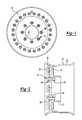
- FIG. 1is a plan view of a wheel assembly including a sleeve constructed in accordance with the teachings of the present disclosure
- FIG. 2is a cross-sectional side view of the wheel assembly depicted in FIG. 1 ;
- FIG. 3is an enlarged fragmentary cross-sectional view of the wheel assembly
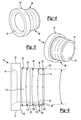
- FIG. 4is a perspective view of a sleeve
- FIG. 5is another perspective view of the sleeve.
- FIG. 6is a cross-sectional side view of the sleeve.
- FIGS. 1-3depict an exemplary non-ferrous, aluminum wheel 10 fixed for rotation with a rotatable hub 12 by a fastener assembly 14 .
- Wheel 10includes a mounting flange 16 including a central aperture 18 and a plurality of wheel stud apertures 20 circumferentially spaced apart from one another.
- Each aperture 20is shaped as a counterbore including a tapered or conical portion defined by a wall 22 and a cylindrical portion defined by a wall 24 .
- a land 26extends radially outwardly from wall 22 to wall 24 .
- Wheel 10is shown as a two-piece wheel including an outer ring 30 fixed to an inner ring 32 with a plurality of threaded fasteners 34 .
- This wheel constructionis merely exemplary. It should be appreciated that the wheel mounting arrangement of the present disclosure may be used in conjunction with any number of singular or multi-piece wheels.
- Hub 12includes an axially protruding pilot 38 with a cylindrical surface 40 having an outer diameter slightly less than an inner diameter of aperture 18 .
- a plurality of wheel studs 44are fixed to hub 12 via a splined or knurled interference coupling 46 .
- Each wheel stud 44extends through a corresponding wheel stud aperture 20 and includes an externally threaded portion 50 .
- Wheel fastener assembly 14includes a sleeve 54 and a lug nut 56 .
- Lug nut 56may be constructed from steel and include an internal thread 58 in engagement with external thread 50 of wheel stud 44 .
- Lug nut 56also includes a plurality of flats 60 for engagement with a driving tool such as a socket.
- a substantially spherical surface 62is formed on the end of lug nut 56 that engages sleeve 54 . Surface 62 may partially deform during engagement with sleeve 54 .
- FIGS. 4-6depict sleeve 54 in greater detail.
- Sleeve 54is formed from a heat treated steel such as SAE 4140.
- Sleeve 54includes a tapered and barbed body portion 68 as well as a flanged head 70 .
- a bore 72extends through sleeve 54 and includes a conically shaped seat portion 74 as well as a cylindrically shaped portion 76 .
- Flanged head 70includes an outer substantially cylindrical surface 78 that remains clear of wall 24 .
- a substantially planar surface 80 of flanged head 70engages land 26 of wheel 10 once sleeve 54 has been coupled to wheel 10 .
- An external profile of body portion 68includes first through fifth frusto-conical surfaces 84 , 86 , 88 , 90 , 92 positioned adjacent to one another.
- First conical surface 84intersects an end face 96 of sleeve 54 .
- First conical surface 84includes a minimum diameter at a circle 100 intersecting end face 96 and extends radially outwardly at an included angle A of approximately 17° to a first back face 102 .
- Second conical surface 86includes a minimum diameter at a circle 104 intersecting back face 102 .
- the diameter of second conical surface 86 at circle 104is less than the maximum diameter of first conical surface 84 .
- a stepped and barbed geometryis defined.
- Second conical face 86extends at an included angle B of approximately 8.3° to a second back face 108 .
- the axial length of second conical surface 86is more than twice the axial length of first conical surface 84 .
- Third conical surface 88includes a minimum diameter circle 110 at the intersection of second back face 108 .
- the minimum diameter of third conical surface 88is less than the maximum diameter defined by second conical surface 86 such that another barbed and stepped transition exists at second back face 108 .
- Third conical surface 88also extends at an included angle C of approximately 8.3° to a third back face 112 .
- Fourth conical surface 90also extends at a similar included angle D of 8.3° to a fourth back face 114 .
- Fourth conical surface 90includes a minimum diameter portion at a circle 120 having a diameter less than the maximum diameter portion of third conical surface 88 .
- a similar stepped arrangementexists between fourth conical surface 90 and fifth conical surface 92 .
- Fifth conical surface 92extends at an included angle E of approximately 5.6°. It is contemplated that the minimum diameter defined by first conical surface 84 at circle 100 is less than the minimum inner diameter of wall 22 .
- at least one of the conical surfaces 84 , 86 , 88 , 90 , 92includes an outer diameter that is greater than the inner diameter of wall 22 . Based on the direction of insertion, the tapered conical surfaces, and the fact that sleeve 54 is constructed from a hardened steel, the non-ferrous material of wheel 10 displaces to allow insertion of sleeve 54 within aperture 20 .
- Sleeves 54are inserted within apertures 20 and driven to a final seated position through the use of a press and/or lug nuts 56 .
- sleeves 54continue to be axially translated until surface 80 engages land 26 .
- at least one of conical surfaces 84 , 86 , 88 , 90 , 92engages tapered wall 22 of aperture 20 in an interference fit. In one arrangement, the maximum diameter portion of each barb will biasedly engage wall 22 prior to sleeve 54 being fully inserted.
- each conical surface 84 , 86 , 88 , 90 , 92may be positioned axially spaced apart from one another to define a tapered profile of sleeve 54 .
- An included angle F of the tapered profileis substantially similar to the profile of wall 22 .
- sleeves 54are permanently coupled to wheel 10 due to the tapered and barbed shape of the outer surfaces previously described. Sleeves 54 will maintain a fixed relationship to wheel 10 regardless of the presence of absence of a clamping load from lug nuts 56 .
Landscapes
- Engineering & Computer Science (AREA)
- Mechanical Engineering (AREA)
- General Engineering & Computer Science (AREA)
- Connection Of Plates (AREA)
- Dowels (AREA)
Abstract
Description
Claims (19)
Priority Applications (1)
| Application Number | Priority Date | Filing Date | Title |
|---|---|---|---|
| US12/832,362US8308247B2 (en) | 2010-07-08 | 2010-07-08 | Wheel mounting sleeve |
Applications Claiming Priority (1)
| Application Number | Priority Date | Filing Date | Title |
|---|---|---|---|
| US12/832,362US8308247B2 (en) | 2010-07-08 | 2010-07-08 | Wheel mounting sleeve |
Publications (2)
| Publication Number | Publication Date |
|---|---|
| US20120007416A1 US20120007416A1 (en) | 2012-01-12 |
| US8308247B2true US8308247B2 (en) | 2012-11-13 |
Family
ID=45438073
Family Applications (1)
| Application Number | Title | Priority Date | Filing Date |
|---|---|---|---|
| US12/832,362Active2031-04-01US8308247B2 (en) | 2010-07-08 | 2010-07-08 | Wheel mounting sleeve |
Country Status (1)
| Country | Link |
|---|---|
| US (1) | US8308247B2 (en) |
Cited By (3)
| Publication number | Priority date | Publication date | Assignee | Title |
|---|---|---|---|---|
| US20130002006A1 (en)* | 2011-06-29 | 2013-01-03 | Rick Pruden | Variable lug insert for wheel opening |
| AU2016202195B1 (en)* | 2016-04-08 | 2017-06-15 | Alex Global Technology, Inc. | Reinforcing structure of locking holes of trucks’ wheels |
| US10247218B2 (en)* | 2015-03-10 | 2019-04-02 | Sikorsky Aircraft Corporation | Brushing retention of threaded fastener |
Families Citing this family (1)
| Publication number | Priority date | Publication date | Assignee | Title |
|---|---|---|---|---|
| DE102013205797B4 (en)* | 2013-04-02 | 2023-08-03 | Bayerische Motoren Werke Aktiengesellschaft | Device for fastening a wheel disc made of fiber composite material |
Citations (31)
| Publication number | Priority date | Publication date | Assignee | Title |
|---|---|---|---|---|
| US1607274A (en)* | 1924-10-10 | 1926-11-16 | Firm Of French & Hecht | Means for attaching parts or members together |
| US1889837A (en)* | 1930-01-10 | 1932-12-06 | Michelin & Cie | Means for securing removable wheels to a hub |
| US2279954A (en)* | 1941-04-28 | 1942-04-14 | Harry E Sipe | Shafting connection |
| US2352487A (en)* | 1942-09-11 | 1944-06-27 | Int Harvester Co | Wheel |
| US4310273A (en) | 1979-04-30 | 1982-01-12 | Textron Inc. | Fastener assembly |
| US4679860A (en) | 1984-12-21 | 1987-07-14 | Honda Giken Kogyo Kabushiki Kaisha | Wheel assembly for vehicle |
| JPS62163801A (en)* | 1986-01-13 | 1987-07-20 | Kanai Hiroyuki | Nut seat bush for aluminum wheel and mounting method thereof |
| US4708397A (en) | 1986-08-12 | 1987-11-24 | Weinmann Paul R | Motor vehicle wheel mounting means and method |
| US4898429A (en) | 1988-07-25 | 1990-02-06 | Plumer Mark J | Wheel nut assembly |
| US5026122A (en) | 1981-12-03 | 1991-06-25 | Vatroslav Grubisic | Wheel for a commercial vehicle |
| US5056870A (en) | 1988-07-25 | 1991-10-15 | Plumer Mark J | Wheel nut assembly |
| US5094579A (en) | 1990-10-19 | 1992-03-10 | Johnson H Thad | Fastener and grommet assembly providing axial play |
| US5401079A (en) | 1991-08-26 | 1995-03-28 | The Goodyear Tire & Rubber Company | Heat transfer preventing lug hole sleeve inserts for a plastic wheel |
| US5452944A (en) | 1994-07-05 | 1995-09-26 | Bear; Richard W. | Device for adhering lug nuts to vehicle wheels |
| US5454628A (en) | 1992-08-18 | 1995-10-03 | Stahlschmidt & Maiworm Gmbh | Configuration for preventing contact corrosion in magnesium wheels |
| US5542753A (en) | 1994-01-27 | 1996-08-06 | Plumer; Mark J. | Wheel opening inserts and lug nut assemblies thereof for mounting non-ferrous vehicle wheels |
| US5711581A (en)* | 1994-01-27 | 1998-01-27 | Plumer; Mark J. | Wheel opening inserts and lug nut assemblies thereof for mounting vehicle wheels |
| US6068344A (en) | 1996-08-29 | 2000-05-30 | Nether; Joseph G. | Wheel mount |
| US6092968A (en) | 1998-05-29 | 2000-07-25 | Mcgard, Inc. | Fastener structure |
| US6106077A (en) | 1996-08-19 | 2000-08-22 | Dr. Ing. H.C.F. Porsche Ag | Wheel bolt |
| US6296319B1 (en)* | 1997-12-06 | 2001-10-02 | Dr. Ing. H.C.F. Porsche Ag | Fastening arrangement for a vehicle wheel consisting of an interior wheel shell and of an exterior wheel shell |
| US6439816B1 (en) | 2001-02-12 | 2002-08-27 | James Noland Nance | Lug nut assembly |
| US6478521B1 (en) | 1999-09-08 | 2002-11-12 | Dr. Ing. H.C.F. Porsche Ag | Washer element for a wheel bolt and/or wheel nut of a motor vehicle wheel |
| US6715843B2 (en) | 2002-02-04 | 2004-04-06 | Kent's Tire Service, Inc. | Wheel mounting assembly and method |
| US20040165967A1 (en) | 2002-12-03 | 2004-08-26 | Alexander Winker | Wheel nut and fastening element |
| US20050163589A1 (en) | 2000-10-10 | 2005-07-28 | Wilson Larry J. | Steel washer integral with nut/cap assembly |
| US20060163937A1 (en) | 2005-01-21 | 2006-07-27 | Andersen James H | Drum and wheel centering sleeve, kit and method |
| US20070007816A1 (en) | 2005-07-08 | 2007-01-11 | Ford Global Technologies, Llc | Non-axisymmetrical wheel cover retention apparatuses and assemblies |
| US7252471B1 (en) | 2006-09-21 | 2007-08-07 | Dexter Axel Company | Swivel nut |
| US7290838B2 (en) | 2002-03-22 | 2007-11-06 | Honda Giken Kogyo Kabushiki Kaisha | Vehicle wheel |
| US20090218878A1 (en) | 2008-03-03 | 2009-09-03 | Lippis Daniel J | Wheel hub |
- 2010
- 2010-07-08USUS12/832,362patent/US8308247B2/enactiveActive
Patent Citations (33)
| Publication number | Priority date | Publication date | Assignee | Title |
|---|---|---|---|---|
| US1607274A (en)* | 1924-10-10 | 1926-11-16 | Firm Of French & Hecht | Means for attaching parts or members together |
| US1889837A (en)* | 1930-01-10 | 1932-12-06 | Michelin & Cie | Means for securing removable wheels to a hub |
| US2279954A (en)* | 1941-04-28 | 1942-04-14 | Harry E Sipe | Shafting connection |
| US2352487A (en)* | 1942-09-11 | 1944-06-27 | Int Harvester Co | Wheel |
| US4310273A (en) | 1979-04-30 | 1982-01-12 | Textron Inc. | Fastener assembly |
| US5026122A (en) | 1981-12-03 | 1991-06-25 | Vatroslav Grubisic | Wheel for a commercial vehicle |
| US4679860A (en) | 1984-12-21 | 1987-07-14 | Honda Giken Kogyo Kabushiki Kaisha | Wheel assembly for vehicle |
| JPS62163801A (en)* | 1986-01-13 | 1987-07-20 | Kanai Hiroyuki | Nut seat bush for aluminum wheel and mounting method thereof |
| US4708397A (en) | 1986-08-12 | 1987-11-24 | Weinmann Paul R | Motor vehicle wheel mounting means and method |
| US4898429A (en) | 1988-07-25 | 1990-02-06 | Plumer Mark J | Wheel nut assembly |
| US5056870A (en) | 1988-07-25 | 1991-10-15 | Plumer Mark J | Wheel nut assembly |
| US5094579A (en) | 1990-10-19 | 1992-03-10 | Johnson H Thad | Fastener and grommet assembly providing axial play |
| US5401079A (en) | 1991-08-26 | 1995-03-28 | The Goodyear Tire & Rubber Company | Heat transfer preventing lug hole sleeve inserts for a plastic wheel |
| US5454628A (en) | 1992-08-18 | 1995-10-03 | Stahlschmidt & Maiworm Gmbh | Configuration for preventing contact corrosion in magnesium wheels |
| US5711581A (en)* | 1994-01-27 | 1998-01-27 | Plumer; Mark J. | Wheel opening inserts and lug nut assemblies thereof for mounting vehicle wheels |
| US5542753A (en) | 1994-01-27 | 1996-08-06 | Plumer; Mark J. | Wheel opening inserts and lug nut assemblies thereof for mounting non-ferrous vehicle wheels |
| US5452944A (en) | 1994-07-05 | 1995-09-26 | Bear; Richard W. | Device for adhering lug nuts to vehicle wheels |
| US6106077A (en) | 1996-08-19 | 2000-08-22 | Dr. Ing. H.C.F. Porsche Ag | Wheel bolt |
| US6068344A (en) | 1996-08-29 | 2000-05-30 | Nether; Joseph G. | Wheel mount |
| US6296319B1 (en)* | 1997-12-06 | 2001-10-02 | Dr. Ing. H.C.F. Porsche Ag | Fastening arrangement for a vehicle wheel consisting of an interior wheel shell and of an exterior wheel shell |
| US6092968A (en) | 1998-05-29 | 2000-07-25 | Mcgard, Inc. | Fastener structure |
| US6357981B1 (en) | 1998-05-29 | 2002-03-19 | Mcgard, Inc. | Fastener structure |
| US6478521B1 (en) | 1999-09-08 | 2002-11-12 | Dr. Ing. H.C.F. Porsche Ag | Washer element for a wheel bolt and/or wheel nut of a motor vehicle wheel |
| US20050163589A1 (en) | 2000-10-10 | 2005-07-28 | Wilson Larry J. | Steel washer integral with nut/cap assembly |
| US6439816B1 (en) | 2001-02-12 | 2002-08-27 | James Noland Nance | Lug nut assembly |
| US6715843B2 (en) | 2002-02-04 | 2004-04-06 | Kent's Tire Service, Inc. | Wheel mounting assembly and method |
| US7290838B2 (en) | 2002-03-22 | 2007-11-06 | Honda Giken Kogyo Kabushiki Kaisha | Vehicle wheel |
| US20040165967A1 (en) | 2002-12-03 | 2004-08-26 | Alexander Winker | Wheel nut and fastening element |
| US20060163937A1 (en) | 2005-01-21 | 2006-07-27 | Andersen James H | Drum and wheel centering sleeve, kit and method |
| US7111909B2 (en)* | 2005-01-21 | 2006-09-26 | Andersen James H | Drum and wheel centering sleeve, kit and method |
| US20070007816A1 (en) | 2005-07-08 | 2007-01-11 | Ford Global Technologies, Llc | Non-axisymmetrical wheel cover retention apparatuses and assemblies |
| US7252471B1 (en) | 2006-09-21 | 2007-08-07 | Dexter Axel Company | Swivel nut |
| US20090218878A1 (en) | 2008-03-03 | 2009-09-03 | Lippis Daniel J | Wheel hub |
Cited By (4)
| Publication number | Priority date | Publication date | Assignee | Title |
|---|---|---|---|---|
| US20130002006A1 (en)* | 2011-06-29 | 2013-01-03 | Rick Pruden | Variable lug insert for wheel opening |
| US8911026B2 (en)* | 2011-06-29 | 2014-12-16 | Rick Pruden | Variable lug insert for wheel opening |
| US10247218B2 (en)* | 2015-03-10 | 2019-04-02 | Sikorsky Aircraft Corporation | Brushing retention of threaded fastener |
| AU2016202195B1 (en)* | 2016-04-08 | 2017-06-15 | Alex Global Technology, Inc. | Reinforcing structure of locking holes of trucks’ wheels |
Also Published As
| Publication number | Publication date |
|---|---|
| US20120007416A1 (en) | 2012-01-12 |
Similar Documents
| Publication | Publication Date | Title |
|---|---|---|
| JP7145604B2 (en) | Tapered lead-in for interference fit fasteners | |
| US6543979B2 (en) | Clinch nut assembly and method of producing clinch nut | |
| US9321301B2 (en) | Attachment arrangement for composite wheels | |
| US5380071A (en) | Vehicle wheel and method of manufacture of the same | |
| US8579510B2 (en) | Rotatable bar pin bushing assembly | |
| JP6421186B2 (en) | Center lock mounting structure for composite wheels | |
| EP1422427A1 (en) | Decorative capped wheel nut or bolt assembly and method of assembly | |
| US20070189878A1 (en) | Decorative capped wheel nut or bolt assembly and method | |
| US8308247B2 (en) | Wheel mounting sleeve | |
| US11060554B2 (en) | Fastener assembly and method | |
| JP2002536607A (en) | Support device for functional units | |
| WO1995011403A1 (en) | Clamping collar | |
| US10882553B2 (en) | Kingpin assembly with a torque receiving configuration | |
| US20040021365A1 (en) | Two-piece vehicle wheel | |
| US20120175940A1 (en) | Sleeve nut | |
| US20120263558A1 (en) | Hub centric wheel fastener | |
| US8469461B2 (en) | Universal wheel hub | |
| US11975567B2 (en) | Hub bearing constant velocity joint | |
| JP5740543B2 (en) | Swage display color | |
| US20100278609A1 (en) | Supportive welded box section collar | |
| US12378988B2 (en) | Tapered fastener | |
| US20220325742A1 (en) | Coated fastener body | |
| WO2017057310A1 (en) | Wheel for vehicles | |
| JP2569823Y2 (en) | Ring joint fitting for steel segment | |
| AU2014100912A4 (en) | Improvements Relating to Security Bolting |
Legal Events
| Date | Code | Title | Description |
|---|---|---|---|
| AS | Assignment | Owner name:FORGITRON TECHNOLOGIES, LLC, SOUTH CAROLINA Free format text:ASSIGNMENT OF ASSIGNORS INTEREST;ASSIGNOR:KAZMIERZAK, RICHARD R.;REEL/FRAME:024653/0326 Effective date:20100708 | |
| AS | Assignment | Owner name:KELTIC FINANCIAL PARTNERS II, LP, NEW YORK Free format text:RIDER TO GENERAL SECURITY AGREEMENT-PATENTS;ASSIGNOR:FORGITRON TECHNOLOGIES, LLC;REEL/FRAME:026227/0858 Effective date:20110412 | |
| AS | Assignment | Owner name:FORGITRON TECHNOLOGIES, LLC, SOUTH CAROLINA Free format text:RELEASE BY SECURED PARTY;ASSIGNOR:KELTIC FINANCIAL PARTNERS II, LP;REEL/FRAME:026479/0184 Effective date:20110620 | |
| AS | Assignment | Owner name:ACCURIDE EMI, LLC, SOUTH CAROLINA Free format text:ASSIGNMENT OF ASSIGNORS INTEREST;ASSIGNOR:FORGITRON TECHNOLOGIES LLC;REEL/FRAME:026494/0867 Effective date:20110617 | |
| AS | Assignment | Owner name:DEUTSCHE BANK TRUST COMPANY AMERICAS, AS NOTES PRI Free format text:INTELLECTUAL PROPERTY SECURITY AGREEMENT SUPPLEMENT;ASSIGNOR:ACCURIDE EMI, LLC;REEL/FRAME:026761/0199 Effective date:20110816 | |
| STCF | Information on status: patent grant | Free format text:PATENTED CASE | |
| AS | Assignment | Owner name:ACCURIDE CORPORATION, ACCURIDE EMI, LLC, AND GUNIT Free format text:RELEASE BY SECURED PARTY AS SECURITY AGENT;ASSIGNOR:DEUTSCHE BANK COMPANY AMERICAS, A NEW YORK BANKING CORPORATION, AS SECURITY AGENT;REEL/FRAME:030816/0281 Effective date:20130711 Owner name:WELLS FARGO BANK, NATIONAL ASSOCIATION, AS AGENT, Free format text:SECURITY AGREEMENT;ASSIGNOR:ACCURIDE CORPORATION, ACCURIDE EMI, LLC AND GUNITE CORPORATION;REEL/FRAME:030821/0300 Effective date:20130711 | |
| FPAY | Fee payment | Year of fee payment:4 | |
| AS | Assignment | Owner name:ACCURIDE EMI, LLC, INDIANA Free format text:RELEASE BY SECURED PARTY;ASSIGNOR:WELLS FARGO BANK, NATIONAL ASSOCIATION;REEL/FRAME:040680/0480 Effective date:20161118 Owner name:ACCURIDE CORPORATION, INDIANA Free format text:RELEASE BY SECURED PARTY;ASSIGNOR:WELLS FARGO BANK, NATIONAL ASSOCIATION;REEL/FRAME:040680/0480 Effective date:20161118 Owner name:GUNITE CORPORATION, INDIANA Free format text:RELEASE BY SECURED PARTY;ASSIGNOR:WELLS FARGO BANK, NATIONAL ASSOCIATION;REEL/FRAME:040680/0480 Effective date:20161118 Owner name:ROYAL BANK OF CANADA, CANADA Free format text:ABL CREDIT AGREEMENT;ASSIGNORS:ACCURIDE CORPORATION;GUNITE CORPORATION;ACCURIDE EMI, LLC;REEL/FRAME:040680/0557 Effective date:20161118 Owner name:ROYAL BANK OF CANADA, ONTARIO Free format text:SECURITY INTEREST;ASSIGNORS:ACCURIDE CORPORATION;GUNITE CORPORATION;ACCURIDE EMI;REEL/FRAME:040800/0267 Effective date:20161118 | |
| AS | Assignment | Owner name:BANK OF AMERICA, N.A., AS SUCCESSOR AGENT, NORTH C Free format text:PATENT SECURITY INTEREST ASSIGNMENT AGREEMENT;ASSIGNOR:ROYAL BANK OF CANADA;REEL/FRAME:047287/0054 Effective date:20180601 | |
| MAFP | Maintenance fee payment | Free format text:PAYMENT OF MAINTENANCE FEE, 8TH YEAR, LARGE ENTITY (ORIGINAL EVENT CODE: M1552); ENTITY STATUS OF PATENT OWNER: LARGE ENTITY Year of fee payment:8 | |
| MAFP | Maintenance fee payment | Free format text:PAYMENT OF MAINTENANCE FEE, 12TH YEAR, LARGE ENTITY (ORIGINAL EVENT CODE: M1553); ENTITY STATUS OF PATENT OWNER: LARGE ENTITY Year of fee payment:12 | |
| AS | Assignment | Owner name:ALTER DOMUS (US) LLC, AS SUCCESSOR COLLATERAL AGENT, ILLINOIS Free format text:ASSIGNMENT TO SECURITY INTEREST IN PATENTS AT REEL 040680/FRAME 0557 TO SUCCESSOR COLLATERAL AGENT BY RESIGNING COLLATERAL AGENT;ASSIGNOR:ROYAL BANK OF CANADA, AS RESIGNING COLLATERAL AGENT;REEL/FRAME:068549/0776 Effective date:20240807 | |
| AS | Assignment | Owner name:BANK OF AMERICA, N.A., AS COLLATERAL AGENT, NORTH CAROLINA Free format text:PATENT SECURITY AGREEMENT;ASSIGNORS:ACCURIDE CORPORATION;ACCURIDE EMI, LLC;REEL/FRAME:070454/0961 Effective date:20250307 Owner name:KIC LLC, WASHINGTON Free format text:RELEASE BY SECURED PARTY;ASSIGNOR:ALTER DOMUS (US) LLC, AS PREPETITION AGENT;REEL/FRAME:070464/0012 Effective date:20250307 Owner name:GUNITE CORPORATION, INDIANA Free format text:RELEASE BY SECURED PARTY;ASSIGNOR:ALTER DOMUS (US) LLC, AS PREPETITION AGENT;REEL/FRAME:070464/0012 Effective date:20250307 Owner name:ACCURIDE CORPORATION, INDIANA Free format text:RELEASE BY SECURED PARTY;ASSIGNOR:ALTER DOMUS (US) LLC, AS PREPETITION AGENT;REEL/FRAME:070464/0012 Effective date:20250307 Owner name:ACCURIDE EMI, LLC, MICHIGAN Free format text:RELEASE OF U.S. SECURITY INTEREST IN PATENTS;ASSIGNOR:BANK OF AMERICA, N.A.;REEL/FRAME:070454/0744 Effective date:20250307 Owner name:GUNITE CORPORATION, INDIANA Free format text:RELEASE OF U.S. SECURITY INTEREST IN PATENTS;ASSIGNOR:BANK OF AMERICA, N.A.;REEL/FRAME:070454/0744 Effective date:20250307 Owner name:KIC LLC, WASHINGTON Free format text:RELEASE OF U.S. SECURITY INTEREST IN PATENTS;ASSIGNOR:BANK OF AMERICA, N.A.;REEL/FRAME:070454/0744 Effective date:20250307 Owner name:ACCURIDE CORPORATION, MICHIGAN Free format text:RELEASE OF U.S. SECURITY INTEREST IN PATENTS;ASSIGNOR:BANK OF AMERICA, N.A.;REEL/FRAME:070454/0744 Effective date:20250307 |