US8308167B2 - Locking mechanism with quick disassembly means - Google Patents
Locking mechanism with quick disassembly meansDownload PDFInfo
- Publication number
- US8308167B2 US8308167B2US12/341,760US34176008AUS8308167B2US 8308167 B2US8308167 B2US 8308167B2US 34176008 AUS34176008 AUS 34176008AUS 8308167 B2US8308167 B2US 8308167B2
- Authority
- US
- United States
- Prior art keywords
- locking mechanism
- groove
- tongue
- piston
- housing
- Prior art date
- Legal status (The legal status is an assumption and is not a legal conclusion. Google has not performed a legal analysis and makes no representation as to the accuracy of the status listed.)
- Active, expires
Links
Images


Classifications
- B—PERFORMING OPERATIONS; TRANSPORTING
- B23—MACHINE TOOLS; METAL-WORKING NOT OTHERWISE PROVIDED FOR
- B23B—TURNING; BORING
- B23B31/00—Chucks; Expansion mandrels; Adaptations thereof for remote control
- B23B31/02—Chucks
- B23B31/10—Chucks characterised by the retaining or gripping devices or their immediate operating means
- A—HUMAN NECESSITIES
- A61—MEDICAL OR VETERINARY SCIENCE; HYGIENE
- A61B—DIAGNOSIS; SURGERY; IDENTIFICATION
- A61B17/00—Surgical instruments, devices or methods
- A61B17/16—Instruments for performing osteoclasis; Drills or chisels for bones; Trepans
- A61B17/1613—Component parts
- A61B17/162—Chucks or tool parts which are to be held in a chuck
- H—ELECTRICITY
- H01—ELECTRIC ELEMENTS
- H01R—ELECTRICALLY-CONDUCTIVE CONNECTIONS; STRUCTURAL ASSOCIATIONS OF A PLURALITY OF MUTUALLY-INSULATED ELECTRICAL CONNECTING ELEMENTS; COUPLING DEVICES; CURRENT COLLECTORS
- H01R13/00—Details of coupling devices of the kinds covered by groups H01R12/70 or H01R24/00 - H01R33/00
- H01R13/02—Contact members
- H01R13/22—Contacts for co-operating by abutting
- H01R13/24—Contacts for co-operating by abutting resilient; resiliently-mounted
- H01R13/2407—Contacts for co-operating by abutting resilient; resiliently-mounted characterized by the resilient means
- H01R13/2421—Contacts for co-operating by abutting resilient; resiliently-mounted characterized by the resilient means using coil springs
- H—ELECTRICITY
- H01—ELECTRIC ELEMENTS
- H01R—ELECTRICALLY-CONDUCTIVE CONNECTIONS; STRUCTURAL ASSOCIATIONS OF A PLURALITY OF MUTUALLY-INSULATED ELECTRICAL CONNECTING ELEMENTS; COUPLING DEVICES; CURRENT COLLECTORS
- H01R39/00—Rotary current collectors, distributors or interrupters
- H01R39/64—Devices for uninterrupted current collection
- B—PERFORMING OPERATIONS; TRANSPORTING
- B23—MACHINE TOOLS; METAL-WORKING NOT OTHERWISE PROVIDED FOR
- B23B—TURNING; BORING
- B23B2260/00—Details of constructional elements
- B23B2260/136—Springs
- H—ELECTRICITY
- H01—ELECTRIC ELEMENTS
- H01R—ELECTRICALLY-CONDUCTIVE CONNECTIONS; STRUCTURAL ASSOCIATIONS OF A PLURALITY OF MUTUALLY-INSULATED ELECTRICAL CONNECTING ELEMENTS; COUPLING DEVICES; CURRENT COLLECTORS
- H01R13/00—Details of coupling devices of the kinds covered by groups H01R12/70 or H01R24/00 - H01R33/00
- H01R13/02—Contact members
- H01R13/15—Pins, blades or sockets having separate spring member for producing or increasing contact pressure
- H—ELECTRICITY
- H01—ELECTRIC ELEMENTS
- H01R—ELECTRICALLY-CONDUCTIVE CONNECTIONS; STRUCTURAL ASSOCIATIONS OF A PLURALITY OF MUTUALLY-INSULATED ELECTRICAL CONNECTING ELEMENTS; COUPLING DEVICES; CURRENT COLLECTORS
- H01R13/00—Details of coupling devices of the kinds covered by groups H01R12/70 or H01R24/00 - H01R33/00
- H01R13/62—Means for facilitating engagement or disengagement of coupling parts or for holding them in engagement
- H01R13/639—Additional means for holding or locking coupling parts together, after engagement, e.g. separate keylock, retainer strap
- H—ELECTRICITY
- H01—ELECTRIC ELEMENTS
- H01R—ELECTRICALLY-CONDUCTIVE CONNECTIONS; STRUCTURAL ASSOCIATIONS OF A PLURALITY OF MUTUALLY-INSULATED ELECTRICAL CONNECTING ELEMENTS; COUPLING DEVICES; CURRENT COLLECTORS
- H01R2201/00—Connectors or connections adapted for particular applications
- H01R2201/12—Connectors or connections adapted for particular applications for medicine and surgery
- H—ELECTRICITY
- H01—ELECTRIC ELEMENTS
- H01R—ELECTRICALLY-CONDUCTIVE CONNECTIONS; STRUCTURAL ASSOCIATIONS OF A PLURALITY OF MUTUALLY-INSULATED ELECTRICAL CONNECTING ELEMENTS; COUPLING DEVICES; CURRENT COLLECTORS
- H01R24/00—Two-part coupling devices, or either of their cooperating parts, characterised by their overall structure
- H01R24/58—Contacts spaced along longitudinal axis of engagement
- Y—GENERAL TAGGING OF NEW TECHNOLOGICAL DEVELOPMENTS; GENERAL TAGGING OF CROSS-SECTIONAL TECHNOLOGIES SPANNING OVER SEVERAL SECTIONS OF THE IPC; TECHNICAL SUBJECTS COVERED BY FORMER USPC CROSS-REFERENCE ART COLLECTIONS [XRACs] AND DIGESTS
- Y10—TECHNICAL SUBJECTS COVERED BY FORMER USPC
- Y10T—TECHNICAL SUBJECTS COVERED BY FORMER US CLASSIFICATION
- Y10T279/00—Chucks or sockets
- Y10T279/17—Socket type
- Y10T279/17128—Self-grasping
- Y10T279/17136—Yielding grasping jaws
- Y10T279/17153—Spring jaws
- Y—GENERAL TAGGING OF NEW TECHNOLOGICAL DEVELOPMENTS; GENERAL TAGGING OF CROSS-SECTIONAL TECHNOLOGIES SPANNING OVER SEVERAL SECTIONS OF THE IPC; TECHNICAL SUBJECTS COVERED BY FORMER USPC CROSS-REFERENCE ART COLLECTIONS [XRACs] AND DIGESTS
- Y10—TECHNICAL SUBJECTS COVERED BY FORMER USPC
- Y10T—TECHNICAL SUBJECTS COVERED BY FORMER US CLASSIFICATION
- Y10T279/00—Chucks or sockets
- Y10T279/17—Socket type
- Y10T279/17863—Shouldered-tang holding
- Y—GENERAL TAGGING OF NEW TECHNOLOGICAL DEVELOPMENTS; GENERAL TAGGING OF CROSS-SECTIONAL TECHNOLOGIES SPANNING OVER SEVERAL SECTIONS OF THE IPC; TECHNICAL SUBJECTS COVERED BY FORMER USPC CROSS-REFERENCE ART COLLECTIONS [XRACs] AND DIGESTS
- Y10—TECHNICAL SUBJECTS COVERED BY FORMER USPC
- Y10T—TECHNICAL SUBJECTS COVERED BY FORMER US CLASSIFICATION
- Y10T279/00—Chucks or sockets
- Y10T279/34—Accessory or component
- Y—GENERAL TAGGING OF NEW TECHNOLOGICAL DEVELOPMENTS; GENERAL TAGGING OF CROSS-SECTIONAL TECHNOLOGIES SPANNING OVER SEVERAL SECTIONS OF THE IPC; TECHNICAL SUBJECTS COVERED BY FORMER USPC CROSS-REFERENCE ART COLLECTIONS [XRACs] AND DIGESTS
- Y10—TECHNICAL SUBJECTS COVERED BY FORMER USPC
- Y10T—TECHNICAL SUBJECTS COVERED BY FORMER US CLASSIFICATION
- Y10T403/00—Joints and connections
- Y10T403/60—Biased catch or latch
- Y—GENERAL TAGGING OF NEW TECHNOLOGICAL DEVELOPMENTS; GENERAL TAGGING OF CROSS-SECTIONAL TECHNOLOGIES SPANNING OVER SEVERAL SECTIONS OF THE IPC; TECHNICAL SUBJECTS COVERED BY FORMER USPC CROSS-REFERENCE ART COLLECTIONS [XRACs] AND DIGESTS
- Y10—TECHNICAL SUBJECTS COVERED BY FORMER USPC
- Y10T—TECHNICAL SUBJECTS COVERED BY FORMER US CLASSIFICATION
- Y10T403/00—Joints and connections
- Y10T403/70—Interfitted members
- Y10T403/7047—Radially interposed shim or bushing
- Y10T403/7061—Resilient
Definitions
- the orthopedic and laboratory industriesuse various tools to perform different functions such as drilling, reaming, scraping, filing, etc.
- Quick tool interchangeability and very little play between mating tool partsare important considerations in such industries and wherever quick-change connectors are used.
- different toolscan be quickly interchanged by manually removing and replacing a desired interchangeable component of the main base tool, which can universally attach to a variety of interchangeable components by means of a universal clamp or chuck.
- An example tool utilizing a quick-change connectoris a drill where numerous rotary attachments such as reaming or burring attachments can be interchanged by axial removal and insertion.
- the present embodimentssimplify the method of assembling such tools by providing a rapid means for installing and removing such components.
- Interchangeable components being incorporatedare held in place by individual holders that provide secure axial locking means and quick radial removal means requiring no axial, space for the removal of such components from the main base tool.
- interchangeable component holdersmay be installed in a stationary drill press or a portable drill, depending on the application.
- the holderis permanently secured to the drilling machine and the interchangeable component can be axially or radially installed, axially locked upon installation but radially removable. In the assembled position, the holder provides circumferential concentricity and the component is axially locked.
- the axial locking meansmay comprise, for example, an axially mounted canted-coil spring, in either the stationary or the rotary portion of the holder combination.
- a sleeverestricts radial movement and a non-cylindrical tongue of the interchangeable component and corresponding slot in the holder may allow rotational movement to be transferred between the component and holder.
- a combination of factorscontributes to axial locking motion.
- the combinationmay include one or more of:
- aspects of the present embodimentsinclude a number of different “rotary locking mechanisms with quick radial disassembly means.” with each providing certain useful advantages.
- the embodimentsare configured as providing locking between a housing and a piston.
- the holder and the interchangeable component(s)can correspond to either the piston and housing or housing and piston respectively in reference to the figures of the designs.
- One embodiment of the present locking mechanism for use in quick-release applicationscomprises a housing including a longitudinal axis. A first end portion of the housing includes first and second furcations defining a slot therebetween. An inner surface of the first furcation includes a first groove therein.
- the locking mechanismfurther comprises a piston including a body section. A first end of the body section defines first and second shoulders. A tongue extends away from the shoulders along the longitudinal axis. A surface of the tongue includes a second groove therein.
- the locking mechanismfurther comprises a sleeve slidably engaging an outer surface of the piston body section.
- the locking mechanismfurther comprises a canted-coil spring.
- the locking mechanismfurther comprises a first configuration in which the tongue is disposed within the slot such that the furcations abut the shoulders and the first and second grooves are aligned, the canted-coil spring is disposed within the first and second grooves and is compressed by the first and second grooves, and the sleeve is positioned over at least a portion of a junction between the housing and the piston such that the sleeve engages the outer surface of the piston body section and outer surfaces of the furcations, thereby resisting relative motion of the housing and the piston in a direction perpendicular to the longitudinal axis.
- Another embodiment of the present locking mechanism for use in quick-release applicationscomprises a housing including a longitudinal axis. A first end portion of the housing includes first and second furcations defining a slot therebetween. An inner surface of the first furcation includes a first groove therein. An inner surface of the second furcation includes a second groove therein.
- the locking mechanismfurther comprises a piston including a body section. A first end of the body section defines first and second shoulders. A tongue extends away from the shoulders along the longitudinal axis. A surface of the tongue includes a continuous perimeter groove therein.
- the locking mechanismfurther comprises a sleeve slidably engaging an outer surface of the piston body section.
- the locking mechanismfurther comprises a canted-coil spring disposed within the continuous perimeter groove.
- the locking mechanismfurther comprises a first configuration in which the tongue is disposed within the slot such that the furcations abut the shoulders and the continuous perimeter groove is aligned with the first and second grooves, the canted-coil spring is disposed within the first and second grooves and is compressed by the first and second grooves, and the sleeve is positioned over at least a portion of a junction between the housing and the piston such that the sleeve engages the outer surface of the piston body section and outer surfaces of the furcations, thereby preventing relative motion of the housing and the piston in a direction perpendicular to the longitudinal axis.
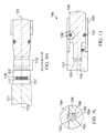
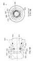
- FIG. 1Ais a cross-sectional front elevation view of one embodiment of a housing portion of the present locking mechanism
- FIG. 1Bis a cross-sectional front elevation view of one embodiment of a piston portion of the present locking mechanism
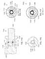
- FIG. 1Cis a cross-sectional front elevation view of the housing portion and the piston portion of FIGS. 1A and 1B in an assembled configuration
- FIG. 1Dis a top plan view of the housing portion and the piston portion of FIGS. 1A and 1B in a partially disassembled configuration
- FIG. 1Eis a cross-sectional left side elevation view of the housing portion and the piston portion of FIGS. 1A and 1B taken through the line E-E in FIG. 1C ;
- FIG. 1Fis a cross-sectional left side elevation view of the housing portion and the piston portion of FIGS. 1A and 1B taken through the line F-F in FIG. 1D :
- FIG. 1Gis a detail view of the portion of FIG. 1C indicated by the circle G;
- FIG. 1His a cross-sectional top plan view of the housing portion and the piston portion of FIGS. 1A and 1B taken through the line H-H in FIGS. 1A and 1B :
- FIG. 1Jis a cross-sectional front elevation view of the housing portion and the piston portion of FIGS. 1A and 1B in an assembled configuration and including an alternative embodiment of the sleeve portion;
- FIG. 1Kis a cross-sectional front elevation view of the housing portion and the piston portion of FIGS. 1A and 1B in an assembled configuration and including an alternative embodiment of the sleeve portion;
- FIG. 1Lis a detail view of the portion of FIG. 1J indicated by the circle L:
- FIG. 1Mis a front elevation view of the axially-canted-coil spring FIG. 1A :
- FIG. 1Nis a front elevation view of the radially-canted-coil spring FIG. 1A :
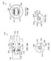
- FIG. 2Ais a cross-sectional front elevation view of another embodiment of the present locking mechanism in an assembled configuration:
- FIG. 2Bis a cross-sectional left side elevation view of the housing portion and the piston portion of FIG. 2A taken through the line B-B in FIG. 2A ;
- FIG. 2Cis a cross-sectional front elevation view of the locking mechanism of FIG. 2A in an improperly assembled configuration:
- FIG. 3Ais a cross-sectional front elevation view of another embodiment of the present locking mechanism in an assembled configuration:
- FIG. 3Bis a cross-sectional left side elevation view of the housing portion and the piston portion of FIG. 3A taken through the line B-B in FIG. 3A :
- FIG. 3Cis a detail view of the portion of FIG. 3A indicated by the circle C;
- FIG. 3Dis a detail cross-sectional bottom plan view of an axial spring portion of FIG. 3A , taken through the line D-D in FIG. 3A ;
- FIG. 3Eis a detail cross-sectional bottom plan view of an axial spring portion of FIG. 3A , taken through the line E-E in FIG. 3A ;
- FIG. 4is a cross-sectional front elevation view of another embodiment of the present locking mechanism in an assembled configuration
- FIG. 5Ais a cross-sectional front elevation view of another embodiment of the present locking mechanism in an assembled configuration:
- FIG. 5Bis a cross-sectional left side elevation view of the housing portion and the piston portion of FIG. 5A taken through the line B-B in FIG. 5A :
- FIG. 5Cis a detail view of the portion of FIG. 5A indicated by the circle C;
- FIG. 5Dis a detail view of the portion of FIG. 5A indicated by the circle D;
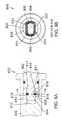
- FIG. 6Ais a cross-sectional front elevation view of another embodiment of the present locking mechanism in an assembled configuration:
- FIG. 6Bis a cross-sectional left side elevation view of the housing portion and the piston portion of FIG. 6A taken through the line B-B in FIG. 6A ;
- FIG. 6Cis a detail view of the portion of FIG. 6A indicated by the circle C:
- FIG. 6Dis a detail view of the portion of FIG. 6A indicated by the circle D:
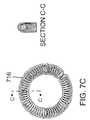
- FIG. 7Ais a cross-sectional front elevation view of another embodiment of the present locking mechanism in an assembled configuration
- FIG. 7Bis a cross-sectional left side elevation view of the housing portion and the piston portion of FIG. 7A taken through the line B-B in FIG. 7A ;
- FIG. 7Cis a front elevation view of the axially-canted-coil spring of FIG. 7A :
- FIG. 8Ais a cross-sectional front elevation view of another embodiment of the present locking mechanism in an assembled configuration:
- FIG. 8Bis a cross-sectional left side elevation view of the housing portion and the piston portion of FIG. 8A taken through the line B-B in FIG. 8A ;
- FIG. 9Ais a cross-sectional front elevation view of another embodiment of the present locking mechanism in an assembled configuration:
- FIG. 9Bis a cross-sectional left side elevation view of the housing portion and the piston portion of FIG. 9A taken through the line B-B in FIG. 9A ;
- FIG. 10is a front perspective view another embodiment of the present locking mechanism in an assembled configuration
- FIG. 10Ais a cross-sectional front elevation view of die housing portion of the locking mechanism of FIG. 10 ;
- FIG. 10Bis a cross-sectional front elevation view of the piston portion of the locking mechanism of FIG. 10 ;
- FIG. 10Cis a cross-sectional front elevation view of the housing portion and the piston portion of FIGS. 10A and 10B in a partially assembled configuration
- FIG. 10Dis a cross-sectional front elevation view of the housing portion and the piston portion of FIGS. 10A and 10B in a fully assembled, configuration
- FIG. 10Eis a cross-sectional left side elevation view of the housing portion and the piston portion of FIG. 10D taken through the line E-E in FIG. 10D ;
- FIG. 10Fis a cross-sectional left side elevation view of the housing portion and the piston portion of FIG. 10C taken through the line F-F in FIG. 10C ;
- FIG. 10Gis a detail view of the portion of FIG. 10D indicated by the circle G;
- FIG. 11is a front perspective view another embodiment of the present locking mechanism in an assembled configuration
- FIG. 11Ais a cross-sectional front elevation view of the housing portion of the locking mechanism of FIG. 11 ;
- FIG. 11Bis a cross-sectional front elevation view of the piston portion of the locking mechanism of FIG. 11 ;
- FIG. 11Cis a cross-sectional front elevation view of the housing portion and the piston portion of FIGS. 11A and 11B in a partially assembled configuration
- FIG. 11Dis a cross-sectional front elevation view of the housing portion and the piston portion of FIGS. 11A and 11B in a fully assembled configuration
- FIG. 11Eis a cross-sectional left side elevation view of the housing portion and the piston portion of FIG. 11D taken through the line E-E in FIG. 11D ;
- FIG. 11Fis a cross-sectional left side elevation view of the housing portion and the piston portion of FIG. 11C taken through the line F-F in FIG. 11C ;
- FIG. 11Gis a detail view of the portion of FIG. 11D indicated by the circle G.
- a canted-coil springcan be either an axial or a radial canted-coil spring. It can also be a hybrid, with characteristics of both axial and radial springs. It can also have different configurations, such as round, oval, square, etc.
- the illustrated embodiments of the present locking mechanism discussed hereininclude canted coil springs.
- the coil springsmay be radially canted, while in certain other embodiments the coil springs may be axially canted. In still further embodiments the coil springs may be both radially canted and axially canted.
- Canted coil springsare described in detail in U.S. Pat. Nos. 4,655,462; 4,826,144; 4,876,781; 4,907,788; 4,915,366; 4,964,204; 5,139,243; 5,160,122; 5,503,375; 5,615,870; 5,709,371; 5,791,638; and 7,055,812. The contents of each of the foregoing patents are hereby incorporated by reference herein.
- FIGS. 1A-1H and 1 J- 1 Millustrate one embodiment of the present locking mechanism 100 .
- the locking mechanism 100includes a generally cylindrical housing 101 having a longitudinal axis 103 .
- the housing 101comprises a first furcation 102 and a second furcation 104 in a first end portion.
- the first and second furcations 102 , 104define a slot 106 therebetween.
- the slot 106is an open space that is shaped substantially as a rectangular parallelepiped, being bounded along three faces by the housing 101 and the furcations 102 , 104 , and being open along the remaining three faces.
- the slot 106may have other configurations.
- an inner surface 107 of the first furcation 102includes a taper bottom groove 108 that retains a linear axially-canted-coil spring 110 .
- the spring lengthruns perpendicular to the longitudinal axis 103 .
- the linear canted-coil spring 110is illustrated in further detail in FIG. 1M .
- the tapered bottom groovemay be located on the second furcation 104 .
- the locking mechanism 100further includes a generally cylindrical piston 112 configured to assemble in-line with the housing 101 .
- the piston 112includes a body section 114 and a longitudinal axis 103 .
- a piston tongue 116extends away from the body section 114 , defining first and second shoulders 118 to either side of the tongue 116 .
- the tongue 116is shaped substantially as a rectangular parallelepiped.
- two opposite faces of the tongue 116are convex so that when the tongue 116 is disposed in the slot 106 an outer surface of the slot 106 /tongue 116 junction is substantially cylindrical.
- the tongue 116may have other shapes.
- a first face 120 of the tongue 116includes a flat bottomed groove 122 .
- the groove 122receives the linear canted-coil spring 110 when the locking mechanism 100 is in the assembled configuration of FIG. 1C .
- the groove 122contributes to the locking action in the locking mechanism 100 , as explained in further detail below.
- the outer surface 124 of the piston 112includes a circumferential groove 126 .
- the circumferential groove 126receives a circular or garter radially-canted-coil spring 128 .
- the circular radially-canted-coil spring 128is illustrated in greater detail in FIG. 1N .
- the circular canted-coil spring 128may be secured inside the circumferential groove 126 by controlling a spring squeeze between the groove 126 and the spring 128 .
- the ends of the groove 126could be pinned or staked such as to cap the channel of the groove to retain the spring 128 therein.
- a generally cylindrical sleeve 130is mounted over the outer surface 124 of the piston 112 .
- the sleeve 130is slidable along the outer surface 124 between the retracted position, of FIG. 1B and the closed position of 1 C.
- the sleeve 130In the retracted position the sleeve 130 is spaced apart from the circular canted-coil spring 128 on a side of the spring 128 opposite the tongue 116 .
- the sleeve 130covers the spring 128 to retain the housing 101 and the piston 112 in the assembled configuration, as described in further detail below.
- the tongue 116is inserted into the slot 106 as illustrated in FIG. 1C .
- the tongue 116may be inserted into the slot 106 by relative axial movement of the housing 101 and the piston 112 , as shown by the arrow 132 in FIGS. 1A , 1 B and 1 H.
- the tongue 116is inserted into the slot 106 until the ends of the furcations 102 , 104 contact the shoulders 118 .
- the groove 122 in the tongue 116at least partially aligns with the groove 108 in the inner surface 107 of the first furcation 102 .
- the linear canted-coil spring 110is thus compressed between the two grooves 108 , 122 as shown in the detail view of FIG. 1G .
- the compressed spring 110provides locking action that prevents the axial separation of the housing 101 and the piston 112 , as described in further detail, below.
- FIG. 1Gshows the manner in which the axial locking occurs.
- the groove width (G.W.)is smaller than the coil height (C.H.).
- a base 134 of the groove 108is tapered such that a depth of the groove increases with increasing distance from a second end portion 136 ( FIG. 1C ) of the housing 101 .
- the taper bottom groove 108facilitates the counter-clockwise rotation of the linear canted-coil spring 110 as the tongue 116 is inserted axially into the slot 106 .
- the relative dimensions of groove width and coil height in combination with the taper bottom groovealso retards the reverse rotation of the coil spring 110 as the tongue 116 is withdrawn axially from the slot 106 , as occurs when a tensile force is applied to the locking mechanism 100 . Consequently, a greater force is required to remove the tongue 116 axially from the slot 106 than is required to insert the tongue 116 axially into the slot 106 .
- the magnitude of the difference between the insertion force and the removal, forcecan be adjusted by adjusting the relative dimensions of groove width and coil height and the angle 144 of the taper bottom groove 108 .
- the angle 144 of the taper bottom groove 108may be tapered to produce a spring in a convex initial position.
- the angleproduces a spring in a concave initial position.
- the magnitude of the removal forcemay be so great that the tongue 116 cannot be removed axially from the slot 106 without destroying the spring 110 .
- the sleeve 130is slid along the piston 112 from the retracted position of FIG. 1B to the closed position of 1 C.
- an end 138 of the sleeve 130abuts a shoulder 140 on the housing 101 to prevent further movement of the sleeve 130 toward the housing 101 .
- the sleeve 130covers the spring 128 and compresses the spring 128 into the circumferential groove 126 , Friction between the spring 128 and the sleeve 130 thus resists sliding movement of the sleeve 130 away from the housing 101 .
- the inner surface of the sleeve 130is smooth.
- the sleeve 130is not locked against sliding movement relative to the piston 112 . Rather, sliding movement relative to the piston 112 is merely retarded by the friction between the spring 128 and the sleeve 130 .
- the sleeve 130In the closed position the sleeve 130 also covers the junction between the tongue 116 and the slot 106 .
- In inner surface of the sleeve 130contacts the outer surfaces of the furcations 102 , 104 and the tongue 116 , as illustrated in the cross-sectional view of FIG. 1E .
- the sleeve 130thus prevents relative movement of the housing 101 and the piston 112 in a direction perpendicular to the longitudinal axis 103 .
- the housing 101 and the piston 112are thus locked because they cannot be separated from one another in either the axial direction (parallel to the longitudinal axis 103 ) or the radial direction (perpendicular to the longitudinal axis 103 ).
- a longitudinally aligned combination tongue-and-groupis incorporated for alignment purposes, which would run parallel to but offset from the longitudinal axis of the piston, instead of the current orthogonal configuration to the longitudinal axis of the piston.
- external markersmay be provided as alignment indicia.
- FIGS. 1D and 1Fillustrate a method of disassembling the housing 101 and the piston. 112 from one another.
- the readerwill note that the cross-sectional view of FIG. 1F is taken through the line F-F in FIG. 1D , but FIG. 1F has been rotated 90° counter-clockwise from the orientation shown in FIG. 1D .
- To disassemble the housing 101 and the piston 112 from, one anotherfirst the sleeve 130 is slid along the piston 112 from the closed position ( FIG. 1C ) to the retracted position ( FIG. 1D ). Next, the housing 101 and the piston 112 are moved relative to one another in the radial direction (perpendicular to the longitudinal axis 103 , as indicated by the arrows 142 in FIGS.
- the compressed linear spring 110resists, but does not prevent, relative sliding movement of the housing 101 and the piston 112 . These components can thus be separated from one another by relative radial movement once the locking sleeve 130 is moved to the retracted position.
- FIGS. 1J , 1 K, and 1 Lillustrate alternate configurations for the present locking mechanism 146 , 148 .
- the sleeve 150includes a circumferential groove 152 on its inner surface.
- the groove 152at least partially aligns with a circumferential taper bottom groove 154 in the piston 156 .
- the groove 152thus receives an axially canted-coil spring 158 and compresses the axially canted-coil spring 158 between the groove 152 and the groove 154 .
- the compressed spring 158resists, but does not prevent the sleeve 150 from sliding away from the housing 101 and out of the locked position.
- the taper bottom groove 154tapers in the opposite direction.
- FIG. 1Killustrates another embodiment 148 in which the piston 164 does not include a circumferential groove retaining a circular coil spring. Instead, the piston 164 includes an end portion 166 having an enlarged outer diameter.
- the sleeve 168includes an annular shoulder 170 formed at a junction between a first inner diameter portion 172 and a second inner diameter portion 174 .
- a coil spring 176(or similar resilient member) is held in compression between the enlarged end portion 166 and the annular shoulder 170 . The compressive force in the spring 176 holds the sleeve 168 in the closed position in which it covers the junction between the furcations 102 , 104 and the tongue 116 .
- An operatormay squeeze the sleeve 168 with his hand (or with a tool) to slide the sleeve 168 along the piston 164 toward the enlarged end portion 166 until it no longer covers the junction between the furcations 102 , 104 and the tongue 116 .
- the housing 101 and piston 164may be separated by relative movement in the radial direction (perpendicular to the longitudinal axis 103 ).
- FIGS. 2A-2Cillustrate another embodiment of the present locking mechanism 200 .
- the locking mechanism 200includes many of the same features described above with respect to the locking mechanism 100 illustrated in FIGS. 1A-1H and 1 J- 1 M. Accordingly, the discussion below will focus on only the differences between the embodiments.
- the tongue 202 of the piston 204is offset from the longitudinal axis 103 .
- the slot 206 of the housing 208is similarly offset from the longitudinal axis 103 .
- the offset of the tongue 202 and the slot 206contribute to proper alignment of the housing 208 and the piston 204 . If the housing 208 and the piston 204 are misaligned, as shown in FIG. 1C , the misalignment will be obvious to the operator.
- the sleeve 210includes an enlarged end portion 212 spaced from the housing 208 .
- the enlarged end portion 212provides a bearing surface 214 for the operator's hand or a tool, facilitating the sliding movement of the sleeve 210 aware from the closed position of FIG. 2A .
- FIGS. 3A-3Eillustrate another embodiment of the present locking mechanism 300 .
- the locking mechanism 300includes many of the same features described above with respect to the locking mechanisms 100 , 200 illustrated in FIGS. 1A-1H , 1 J- 1 M and 2 A- 2 C. Accordingly, the discussion below will focus on only the differences between the embodiments.
- a first surface 301 the tongue 302 of the piston 304includes a taper bottom groove 306 chat retains a linear axially-canted-coil spring 308 .
- a first surface 310 of the first furcation 312 of the housing 314includes a flat bottomed groove 316 . Accordingly, with reference to FIGS.
- the configuration of the grooves 306 , 316 in the locking mechanism 300is the reverse of the configuration of the grooves 108 , 122 in the locking mechanism 100 .
- the function of the grooves 306 , 316is identical to the function of the grooves 108 , 122 , which is described in detail above and will not be repeated here.
- the taper bottom groove 306may extend perpendicular to the longitudinal axis 103 ( FIG. 3D ), or it may lie at a non-perpendicular to the longitudinal axis 103 ( FIG. 3E ).
- the linear canted-coil spring 308assumes the same angle to the longitudinal axis 103 as the groove 306 .
- the illustrated angles for the taper bottom groove 306 and linear canted-coil spring 308are applicable to all of the present embodiments, regardless of whether they are specifically discussed with respect to any particular embodiment.
- FIG. 4illustrates another embodiment of the present locking mechanism 400 .
- the locking mechanism 400includes many of the same features described above with respect to the locking mechanisms 100 , 200 , 300 illustrated in FIGS. 1A-1H , 1 J- 1 M, 2 A- 2 C and 3 A- 3 E. Accordingly, the discussion below will focus on only the differences between the embodiments.
- the tongue 402 of the piston 404includes a step defined by a first portion 406 having a relatively shorter length and a second portion 408 having a relatively longer length.
- the slot 410 in the housing 412similarly includes a step defined by a first portion 414 having a relatively lesser depth and a second portion 416 having a relatively greater depth.
- the stepscontribute to proper alignment of the housing 412 and the piston 404 .
- the tongue 402may only be inserted completely within the slot 410 when the tongue first portion 406 is aligned with the slot first portion 414 and the tongue second portion 408 is aligned with the slot second portion 416 . If the housing 412 and the piston 404 are misaligned, the misalignment will be obvious to the operator.
- FIGS. 5A-5Dillustrate another embodiment of the present locking mechanism 500 .
- the locking mechanism 500includes many of the same features described above with respect to the locking mechanisms 100 , 200 , 300 , 400 illustrated in FIGS. 1A-1H , 1 J- 1 M, 2 A- 2 C, 3 A- 3 E and 4 . Accordingly, the discussion below will focus on only the differences between the embodiments.
- a first surface 502 of the first furcation 504 of the housing 506includes a taper bottom groove 508 that retains a linear axially-canted-coil spring 510 .
- a first surface 512 of the tongue 514 of the piston 516includes a flat bottomed groove 518 .
- a first surface 520 of the second furcation 522 of the housing 506includes a taper bottom, groove 524 that retains a linear canted-coil spring 510 .
- a second surface 526 of the tongue 514 of the piston 516includes a flat bottomed groove 528 .
- the function of the grooves 508 , 518 , 524 , 528is identical to the function of the grooves 108 , 122 , which is described in detail above and will not be repeated here.
- the locking mechanism 500includes two linear canted-coil springs 510 and associated grooves, in certain embodiments it may provide greater axial holding power than the locking mechanisms including only one linear canted-coil spring and associated grooves.
- FIGS. 6A-6Dillustrate another embodiment of the present locking mechanism 600 .
- the locking mechanism 600includes many of the same features described above with respect to the locking mechanisms 100 , 200 , 300 , 400 , 500 illustrated in FIGS. 1A-1H , 1 J- 1 M 2 A- 2 C, 3 A- 3 E, 4 and 5 A- 5 D. Accordingly, the discussion below will focus on only the differences between the embodiments.
- a first surface 602 of the tongue 604 of the piston 606includes a taper bottom groove 608 that retains a linear axially-canted-coil spring 610 .
- a first surface 612 of the first furcation 614 of the housing 616includes a fiat bottomed groove 618 .
- a second surface 620 of the tongue 604 of the housing 606includes a taper bottom groove 622 that retains a linear canted-coil spring 610 .
- a first surface 624 of the second furcation 626 of the piston 616includes a flat bottomed groove 628 .
- the function of the grooves 608 , 618 , 622 , 628is identical to the function of the grooves 306 , 316 , which is described in detail above and will not be repeated here.
- the locking mechanism 600includes two linear canted-coil springs 610 and associated grooves, in certain, embodiments it may provide greater axial holding power than the locking mechanisms including only one linear canted-coil spring and associated grooves.
- FIGS. 7A-7Cillustrate another embodiment of the present locking mechanism 700 .
- the locking mechanism 700includes many of the same features described above with respect to the locking mechanisms 100 , 200 , 300 , 400 , 500 , 600 illustrated in FIGS. 1A-1H , 1 J- 1 M, 2 A- 2 C, 3 A- 3 E, 4 , 5 A- 5 D and 6 A- 6 D. Accordingly, the discussion below will focus on only the differences between the embodiments.
- the locking mechanism 700includes a piston 702 having a tongue 704 .
- the tongue 704has a square cross-section.
- the locking mechanism 700further includes a housing 706 having a first furcation 708 and a second furcation 710 .
- a slot 712 defined between the first and second furcations 708 , 710is sized and configured to receive the square tongue 704 in locking engagement.
- the square tongue 704includes a circumferential taper bottom groove 714 that extends around all four outer faces of the square tongue 704 .
- the circumferential taper bottom groove 714receives and retains a circular, axially-canted-coil spring 716 .
- the circular, axially-canted-coil spring 716is illustrated in greater detail in FIG. 7C .
- inner surfaces 717 of the first and second furcations 708 , 710each include a respective flat bottom groove 718 .
- the circular, axially-canted-coil spring 716is compressed along two portions of its length. Those portions are the first portion 720 ( FIG. 7B ) that lies between a first one of the flat bottom grooves 718 and a first length of the circumferential, taper bottom groove 714 and the second portion 722 ( FIG. 7B ) that lies between a second one of the flat bottom grooves 718 and a second length of the circumferential taper bottom groove 714 .
- the interaction of the grooves 714 , 718 and the compressed spring portions 720 , 722prevents the axial separation of the housing 706 and the piston 702 in the same manner as described above with respect to the previous embodiments.
- the housing 706 and the piston 702may be separated by relative radial movement as also described above with respect to the previous embodiments.
- FIGS. 8A-8Billustrate another embodiment of the present locking mechanism 800 .
- the locking mechanism 800includes many of the same features described above with respect to the locking mechanisms 100 , 200 , 300 , 400 , 500 , 600 , 700 illustrated in FIGS. 1A-1H , 1 J- 1 M, 2 A- 2 C, 3 A- 3 E, 4 , 5 A- 5 D, 6 A- 6 D and 7 A- 7 C. Accordingly, the discussion below will focus on only the differences between the embodiments.
- the locking mechanism 800includes a piston 802 having a tongue 804 .
- the tongue 804has an oval cross-section comprising opposite flat sections 803 and opposite arcuate sections 805 .
- the locking mechanism 800further includes a housing 806 having a first furcation 808 and a second furcation 810 .
- a slot 812 defined between the first and second furcations 808 , 810is sized and configured to receive the oval tongue 804 in locking engagement in which the opposite flat sections 803 engage inner surfaces 817 of the first and second furcations 808 , 810 .
- the oval tongue 804includes a circumferential taper bottom groove 814 that extends around the opposite flat sections 803 and the opposite arcuate sections 805 .
- the circumferential taper bottom groove 814receives and retains a circular, axially-canted-coil spring 816 .
- the first and second furcations 808 , 810each include a respective flat bottom groove 818 .
- the circular, axially-canted-coil spring 816is compressed along two portions of its length. Those portions are the first portion 820 ( FIG. 8B ) that lies between a first one of the fiat bottom grooves 818 and a first length of the circumferential taper bottom groove 814 and the second portion 822 ( FIG. 8B ) that lies between a second one of the flat bottom grooves 818 and a second length of the circumferential taper bottom groove 814 .
- the interaction of the grooves 814 , 818 and the compressed spring portions 820 , 822prevents the axial separation of the housing 806 and the piston 802 in the same manner as described above with respect to the previous embodiments.
- the housing 806 and the piston 802may be separated by relative radial movement as also described above with respect to the previous embodiments.
- FIGS. 9A-9Billustrate another embodiment of the present locking mechanism 900 .
- the locking mechanism 900includes many of the same features described above with respect to the locking mechanisms 100 , 200 , 300 , 400 , 500 , 600 , 700 , 800 illustrated in FIGS. 1A-1H , 1 J- 1 M, 2 A- 2 C, 3 A- 3 E, 4 , 5 A- 5 D, 6 A- 6 D, 7 A- 7 C and 8 A- 8 B. Accordingly, the discussion below will focus on only the differences between the embodiments.
- the locking mechanism 900includes a piston 902 having a tongue 904 .
- the tongue 904has a round cross-section.
- the locking mechanism 900further includes a housing 906 having a first furcation 908 and a second furcation 910 .
- a slot 912 defined between the first and second furcations 908 , 910is sized and configured to receive the round tongue 904 in locking engagement.
- the round tongue 904includes a circumferential taper bottom groove 914 .
- the circumferential taper bottom groove 914receives and retains a circular, axially-canted-coil spring 916 .
- the first and second furcations 908 , 910each include a respective flat bottom groove 918 .
- the circular, axially-canted-coil spring 916is compressed along two portions of its length. Those portions are the first portion 920 ( FIG. 9B ) that lies between a first one of the flat bottom grooves 918 and a first length of the circumferential taper bottom groove 914 and the second portion 922 ( FIG. 9B ) that lies between a second one of the flat bottom grooves 918 and a second length of the circumferential taper bottom groove 914 .
- the interaction of the grooves 914 , 918 and the compressed spring portions 920 , 922prevents the axial separation of the housing 906 and the piston 902 in the same manner as described above with respect to the previous embodiments.
- the housing 906 and the piston 902may be separated by relative radial movement as also described above with respect to the previous embodiments.
- FIGS. 10-10Gillustrate another embodiment of the present locking mechanism 1000 .
- the locking mechanism 1000includes many of the same features described above with respect to the locking mechanisms 100 , 200 , 300 , 400 , 500 , 600 , 700 , 800 , 900 illustrated in FIGS. 1A-1H , 1 J- 1 M, 2 A- 2 C, 3 A- 3 E, 4 , 5 A- 5 D, 6 A- 6 D, 7 A- 7 C, 8 A- 8 B and 9 A- 9 B. Accordingly, the discussion below will focus on only the differences between the embodiments.
- the locking mechanism 1000includes a piston 1002 having a tongue 1004 .
- the tongue 1004has a round cross-section.
- the locking mechanism 1000further includes a housing 1006 having a first furcation 1008 and a second furcation 1010 ( FIGS. 10 and 10E ).
- a wall portion 1011extends between the first and second furcations 1008 , 1010 to form a substantially U-shaped cross-section.
- a slot 1012 bounded by the furcations 1008 , 1010 and the wall portion 1011is sized and configured to receive the round tongue 1004 in locking engagement.
- the round tongue 1004includes a circumferential taper bottom groove 1014 .
- the circumferential taper bottom groove 1014receives and retains a circular, axially-canted-coil spring 1016 .
- the first and second furcations 1008 , 1010 and the wall portion 1011include a flat bottom groove 1018 .
- the circular, axially-canted-coil spring 1016is compressed along approximately half its length in the areas that abut the groove 1018 in the first and second furcations 1008 , 1010 and the wall portion 1011 ( FIG. 10E ).
- the interaction of the grooves 1014 , 1018 and the compressed spring 1016prevents the axial separation of the housing 1006 and the piston 1002 in the same manner as described above with respect to the previous embodiments.
- the housing 1006 and the piston 1002may be separated by relative radial movement as also described above with respect to the previous embodiments and as shown in FIG. 10F .
- FIGS. 11-11Gillustrate another embodiment of the present locking mechanism 1100 .
- the locking mechanism 1100includes many of the same features described above with respect to the locking mechanisms 100 , 200 , 300 , 400 , 500 , 600 , 700 , 800 , 900 , 1000 illustrated in FIGS. 1A-1H , 1 J- 1 M, 2 A- 2 C, 3 A- 3 E, 4 , 5 A- 5 D, 6 A- 6 D, 7 A- 7 C, 8 A- 8 B, 9 A- 9 B and 10 - 10 G. Accordingly, the discussion below will focus on only the differences between the embodiments.
- the locking mechanism 1100includes a piston 1102 having a tongue 1104 .
- the tongue 1104has a round cross-section.
- the locking mechanism 1100further includes a housing 1106 having a first furcation 1108 and a second furcation 1110 ( FIGS. 11 and 11E ).
- a wall portion 1111extends between the first and second furcations 1108 , 1110 to form a substantially U-shaped cross-section.
- a slot 1112 bounded by the furcations 1108 , 1110 and the wall portion 1111is sized and configured to receive the round tongue 1104 in locking engagement.
- the round tongue 1104includes a circumferential taper bottom groove 1114 .
- the circumferential taper bottom groove 1114receives and retains a circular, axially-canted-coil spring 1116 .
- the first and second furcations 1108 , 1110 and the wall portion 1111include a fiat bottom groove 1118 .
- the circular, axially-canted-coil spring 1116is compressed along approximately half its length in the areas that abut the groove 1118 in the first and second furcations 1108 , 1110 and the wall portion 1111 ( FIG. 11E ).
- the interaction of the grooves 1114 , 1118 and the compressed spring 1116prevents the axial separation of the housing 1106 and the piston 1102 in the same manner as described above with respect to the previous embodiments.
- the housing 1106 and the piston 1102may be separated by relative radial movement as also described above with respect to the previous embodiments and as shown in FIG. 11F .
- the locking mechanism 1100does not include a circumferential groove in the body portion 1120 ( FIG. 10 ) of the piston 1102 .
- the locking mechanism 1100includes a sleeve 1122 shaped substantially as a cylinder having a flat side wall 1124 .
- the flat side wall 1124compresses a portion of the spring 1116 into the circumferential groove 1118 . Friction between the spring 1116 and the inner surface of the flat side wall 1124 resists sliding movement of the sleeve 1122 away from the locked position.
- the housingis part of a rotating or reciprocating shaft of equipment or an appliance, such as a drill or a food mixer, and the piston is part of a removable component, such as a chuck.
- the pistonis part of a rotating or reciprocating shaft of equipment or an appliance, and the housing is part of a removable component.
- the removable componentmay be provided with a bore, a socket, a key, a groove, or other mechanical means known in the art for coupling to a tool such as a drill bit, a saw blade, or a food mixer blade, for example.
Landscapes
- Health & Medical Sciences (AREA)
- Surgery (AREA)
- Engineering & Computer Science (AREA)
- Life Sciences & Earth Sciences (AREA)
- Heart & Thoracic Surgery (AREA)
- Medical Informatics (AREA)
- Nuclear Medicine, Radiotherapy & Molecular Imaging (AREA)
- Oral & Maxillofacial Surgery (AREA)
- Dentistry (AREA)
- Biomedical Technology (AREA)
- Mechanical Engineering (AREA)
- Orthopedic Medicine & Surgery (AREA)
- Molecular Biology (AREA)
- Animal Behavior & Ethology (AREA)
- General Health & Medical Sciences (AREA)
- Public Health (AREA)
- Veterinary Medicine (AREA)
- Snaps, Bayonet Connections, Set Pins, And Snap Rings (AREA)
- Jigs For Machine Tools (AREA)
- Gripping On Spindles (AREA)
Abstract
Description
- The groove width is smaller than the coil height so that an interference occurs at assembly between the coil height and the groove width. The interference may range from no interference to approximately 25%, but is preferably between about 5-10% of the coil height so that the spring is firmly retained in the cavity, while at the same time allowing deflection of the spring along the minor axis during locking.
- Interference between the groove height and the coil width along the major axis to reduce or prevent radial movement of the components. Such variation may range from no interference to approximately 15%, but more preferably is under 10%, such as less than 5%.
- Deflection of the spring coils during assembly to achieve locking. The deflection may range from about 1% to the maximum safe deflection of the coil. The maximum safe deflection may be about 15-25% deflection along the minor axis, but not exceeding the safe deflection, that can cause permanent deformation of the spring's coils.
- Tapered locking angle at the bottom of the groove. The taper may range from zero up to about 30%, but is preferably from approximately 5% to approximately 15% to provide a gradual locking action without achieving permanent deformation of the coil.
Claims (26)
Priority Applications (1)
| Application Number | Priority Date | Filing Date | Title |
|---|---|---|---|
| US12/341,760US8308167B2 (en) | 2007-12-21 | 2008-12-22 | Locking mechanism with quick disassembly means |
Applications Claiming Priority (2)
| Application Number | Priority Date | Filing Date | Title |
|---|---|---|---|
| US1591507P | 2007-12-21 | 2007-12-21 | |
| US12/341,760US8308167B2 (en) | 2007-12-21 | 2008-12-22 | Locking mechanism with quick disassembly means |
Publications (2)
| Publication Number | Publication Date |
|---|---|
| US20090160139A1 US20090160139A1 (en) | 2009-06-25 |
| US8308167B2true US8308167B2 (en) | 2012-11-13 |
Family
ID=40787672
Family Applications (1)
| Application Number | Title | Priority Date | Filing Date |
|---|---|---|---|
| US12/341,760Active2031-09-13US8308167B2 (en) | 2007-12-21 | 2008-12-22 | Locking mechanism with quick disassembly means |
Country Status (3)
| Country | Link |
|---|---|
| US (1) | US8308167B2 (en) |
| EP (1) | EP2235421A4 (en) |
| WO (1) | WO2009086327A2 (en) |
Cited By (27)
| Publication number | Priority date | Publication date | Assignee | Title |
|---|---|---|---|---|
| US20120116462A1 (en)* | 2010-11-09 | 2012-05-10 | Alphatec Spine, Inc. | Polyaxial bone screw |
| US20140001327A1 (en)* | 2012-06-29 | 2014-01-02 | Jay H. Penzes | Clamping assembly for flexible conductors used on elevated platforms |
| US20140224829A1 (en)* | 2011-09-21 | 2014-08-14 | Bayer Medical Care Inc. | Continuous Multi-Fluid Delivery System and Method |
| US20150352991A1 (en)* | 2014-06-05 | 2015-12-10 | Amsafe, Inc. | Seatbelt anchor systems for aircraft and other vehicles, and associated methods of manufacture and use |
| US9806473B2 (en) | 2015-01-08 | 2017-10-31 | Bal Seal Engineering, Inc. | High frequency miniature connectors with canted coil springs and related methods |
| US9829028B2 (en) | 2012-11-15 | 2017-11-28 | Bal Seal Engineering, Inc. | Connectors with a pin, a housing, and one or more springs |
| US9882332B2 (en) | 2012-11-30 | 2018-01-30 | Bal Seal Engineering, Inc. | Spring connectors with adjustable grooves and related methods |
| US10151368B2 (en) | 2014-05-02 | 2018-12-11 | Bal Seal Engineering, Inc. | Nested canted coil springs, applications thereof, and related methods |
| US10181668B2 (en) | 2016-06-24 | 2019-01-15 | Bal Seal Engineering, Inc. | Spring contacts and related methods |
| US10186805B2 (en) | 2016-11-17 | 2019-01-22 | Carlisle Interconnect Technologies, Inc. | Electrical connector with locking mechanism |
| US10263379B2 (en) | 2017-03-24 | 2019-04-16 | Bal Seal Engineering, Inc. | Large deflection canted coil springs, connectors, and related methods |
| US10263368B2 (en) | 2013-06-25 | 2019-04-16 | Bal Seal Engineering, Inc. | Electrical contacts with electrically conductive springs |
| US10270198B2 (en) | 2014-09-15 | 2019-04-23 | Bal Seal Engineering, Inc. | Canted coil springs, connectors and related methods |
| US10361528B2 (en) | 2012-09-14 | 2019-07-23 | Bal Seal Engineering, Inc. | Connector housings, use of, and method therefor |
| US10507319B2 (en) | 2015-01-09 | 2019-12-17 | Bayer Healthcare Llc | Multiple fluid delivery system with multi-use disposable set and features thereof |
| US10520001B2 (en) | 2015-03-13 | 2019-12-31 | Bal Seal Engineering, Inc. | Stamped housings to facilitate assembly and related methods |
| US10598241B2 (en) | 2014-02-26 | 2020-03-24 | Bal Seal Engineering, Inc. | Multi deflection canted coil springs and related methods |
| US10655665B2 (en) | 2003-06-04 | 2020-05-19 | Bal Seal Engineering, Inc. | Spring latching connectors |
| US10900531B2 (en) | 2017-08-30 | 2021-01-26 | Bal Seal Engineering, Llc | Spring wire ends to faciliate welding |
| US10935097B2 (en) | 2013-03-14 | 2021-03-02 | Bal Seal Engineering, Llc | Canted coil spring with longitudinal component within and related methods |
| US10965055B2 (en) | 2016-06-24 | 2021-03-30 | Bal Seal Engineering, Llc | Connectors and related methods |
| US11050190B2 (en) | 2016-06-02 | 2021-06-29 | Bal Seal Engineering, Llc | Electrical connectors with linear springs and related methods |
| US11162326B2 (en)* | 2017-05-02 | 2021-11-02 | Weatherford Technology Holdings, Llc | Actuator assembly |
| US11235374B2 (en) | 2012-11-13 | 2022-02-01 | Bal Seal Engineering, Llc | Canted coil springs and assemblies and related methods |
| US11258221B2 (en)* | 2019-07-12 | 2022-02-22 | Oliden Technology, Llc | Rotatable and wet-mateable connector |
| US20220184789A1 (en)* | 2020-12-10 | 2022-06-16 | Chun Po Huang | Removal Apparatus of Threaded Post |
| US20240088593A1 (en)* | 2021-02-16 | 2024-03-14 | Nkt Hv Cables Ab | Cable Lug Device and Method For Mounting A Cable Lug Device |
Families Citing this family (5)
| Publication number | Priority date | Publication date | Assignee | Title |
|---|---|---|---|---|
| CA2708877C (en)* | 2009-07-07 | 2017-10-10 | National Oilwell Varco, L.P. | Retention means for a seal boot used in a universal joint in a downhole motor driveshaft assembly |
| US8336864B2 (en)* | 2009-09-21 | 2012-12-25 | Bal Seal Engineering, Inc. | Longitudinal canted coil spring contacts to facilitate assembly |
| US9004805B2 (en) | 2010-11-30 | 2015-04-14 | Bal Seal Engineering, Inc. | Multi-stage engagement assemblies and related methods |
| CN110404162B (en)* | 2019-08-13 | 2022-02-08 | 山东省肿瘤防治研究院(山东省肿瘤医院) | Butt-joint device is used in installation of stomach tube after gastrointestinal tumour art |
| CN115126951A (en)* | 2022-06-30 | 2022-09-30 | 北京城建集团有限责任公司 | Water pipe connecting device for drainage between foundation pit supporting piles |
Citations (39)
| Publication number | Priority date | Publication date | Assignee | Title |
|---|---|---|---|---|
| US659523A (en)* | 1900-04-12 | 1900-10-09 | North Brothers Mfg Company | Tool-handle fastening. |
| US2336095A (en)* | 1941-04-14 | 1943-12-07 | Teletype Corp | Quick-change chuck |
| US2593794A (en)* | 1947-07-22 | 1952-04-22 | Resina Automatic Machinery Co | Rotatable cap applying chuck with cap gripping helical spring |
| US2999407A (en)* | 1960-06-03 | 1961-09-12 | Arrow Tools Inc | Axial impact tool and work-retainer combination |
| US3610063A (en)* | 1969-11-07 | 1971-10-05 | Lincoln Logotype Co Inc | Spring detent hub |
| US3819194A (en)* | 1972-10-16 | 1974-06-25 | Domain Ind Inc | Tube holder |
| US4678210A (en)* | 1986-08-15 | 1987-07-07 | Peter J. Balsells | Loading and locking mechanism |
| US4804290A (en)* | 1986-08-22 | 1989-02-14 | Peter J. Balsells | Latching and sealing device |
| US4805943A (en) | 1986-08-15 | 1989-02-21 | Peter J. Balsells | Rotary/reciprocating seal apparatus |
| US4902177A (en)* | 1988-10-27 | 1990-02-20 | Terry K. Aitkens | Rapid change tool cutter and driving system |
| US4906031A (en)* | 1988-07-21 | 1990-03-06 | Stratoflex, Inc. | Quick connect coupling with garter spring |
| US5072070A (en)* | 1989-12-01 | 1991-12-10 | Peter J. Balsells | Device for sealing electromagnetic waves |
| US5079388A (en)* | 1989-12-01 | 1992-01-07 | Peter J. Balsells | Gasket for sealing electromagnetic waves |
| US5082390A (en)* | 1991-01-22 | 1992-01-21 | Peter J. Balsells | Latching, holding and locking spring apparatus |
| US5091606A (en)* | 1988-04-25 | 1992-02-25 | Peter J. Balsells | Gasket for sealing electromagnetic waves filled with a conductive material |
| US5117066A (en)* | 1988-04-25 | 1992-05-26 | Peter J. Balsells | Retaining and locking electromagnetic gasket |
| US5226682A (en)* | 1992-07-21 | 1993-07-13 | Aeroquip Corporation | Coupling assembly |
| US5411348A (en)* | 1993-10-26 | 1995-05-02 | Bal Seal Engineering Company, Inc. | Spring mechanism to connect, lock and unlock, members |
| US5474309A (en) | 1993-06-11 | 1995-12-12 | Bal Seal Engineering Company, Inc. | Gasket assembly for sealing electromagnetic waves |
| US5545842A (en)* | 1993-10-26 | 1996-08-13 | Bal Seal Engineering Company, Inc. | Radially mounted spring to connect, lock and unlock, and for snap-on fastening, and for mechanical, electromagnetic shielding, electrical conductivity, and thermal dissipation with environmental sealing |
| US5607006A (en)* | 1994-11-14 | 1997-03-04 | Doehler-Jarvis Technologies, Inc. | Casting method and apparatus for use therein |
| JPH0976105A (en)* | 1995-09-13 | 1997-03-25 | Nikken Kosakusho:Kk | Parts clamping device of spindle |
| US5727821A (en) | 1995-08-04 | 1998-03-17 | Smiths Industries Plc | Fluid couplings |
| KR20000010443U (en) | 1998-11-18 | 2000-06-15 | 이창수 | Hose connector for mold cooling water supply |
| US20020122690A1 (en)* | 2001-03-05 | 2002-09-05 | Daniel Poon | Spring energized connector |
| US20030094812A1 (en)* | 2001-11-21 | 2003-05-22 | Balsells Peter J. | Connector with radial spring |
| US6789826B1 (en)* | 1999-11-18 | 2004-09-14 | Unisys Corporation | Latching system |
| KR20040101972A (en) | 2004-11-12 | 2004-12-03 | 이정호 | Coupling |
| US6835084B2 (en)* | 2002-02-15 | 2004-12-28 | Bal Seal Engineering Co., Inc. | Medically implantable electrical connector with constant conductivity |
| WO2005105207A2 (en) | 2004-04-16 | 2005-11-10 | Bal Seal Engineering Co., Inc. | Use of an axial canted coil spring as an electrical contact to minimize resistivity variations under dynamic loads |
| US7055812B2 (en)* | 2002-09-30 | 2006-06-06 | Bal Seal Engineering Co., Inc. | Canted coil springs various designs |
| US7210398B2 (en)* | 2004-02-18 | 2007-05-01 | Bal Seal Engineering Co., Inc. | Cover seals with latching locking features |
| US20100029145A1 (en)* | 2008-07-30 | 2010-02-04 | Pete Balsells | Canted coil multi-metallic wire |
| US20100090379A1 (en)* | 2003-06-04 | 2010-04-15 | Balsells Peter J | Spring latching connectors |
| US7722415B2 (en)* | 2007-12-06 | 2010-05-25 | Bal Seal Engineering, Inc. | In-line connector |
| US20100289198A1 (en)* | 2009-04-28 | 2010-11-18 | Pete Balsells | Multilayered canted coil springs and associated methods |
| US7999202B2 (en)* | 2008-04-14 | 2011-08-16 | Mitsubishi Electric Corporation | Contact |
| US8057270B2 (en)* | 2007-12-05 | 2011-11-15 | Mitsubishi Electric Corporation | Contact device |
| US8167285B2 (en)* | 2003-06-04 | 2012-05-01 | Bal Seal Engineering Co., Inc. | Spring latching connectors radially and axially mounted |
Family Cites Families (2)
| Publication number | Priority date | Publication date | Assignee | Title |
|---|---|---|---|---|
| FR2313166A1 (en)* | 1975-06-04 | 1976-12-31 | Janin Andre | IMPROVEMENTS TO CUTTING TOOLS WORKING IN ROTATION |
| AUPM681194A0 (en)* | 1994-07-13 | 1994-08-04 | Expertest Pty. Ltd. | Quick connect coupling |
- 2008
- 2008-12-22USUS12/341,760patent/US8308167B2/enactiveActive
- 2008-12-22EPEP08867731.5Apatent/EP2235421A4/ennot_activeWithdrawn
- 2008-12-22WOPCT/US2008/088064patent/WO2009086327A2/enactiveApplication Filing
Patent Citations (39)
| Publication number | Priority date | Publication date | Assignee | Title |
|---|---|---|---|---|
| US659523A (en)* | 1900-04-12 | 1900-10-09 | North Brothers Mfg Company | Tool-handle fastening. |
| US2336095A (en)* | 1941-04-14 | 1943-12-07 | Teletype Corp | Quick-change chuck |
| US2593794A (en)* | 1947-07-22 | 1952-04-22 | Resina Automatic Machinery Co | Rotatable cap applying chuck with cap gripping helical spring |
| US2999407A (en)* | 1960-06-03 | 1961-09-12 | Arrow Tools Inc | Axial impact tool and work-retainer combination |
| US3610063A (en)* | 1969-11-07 | 1971-10-05 | Lincoln Logotype Co Inc | Spring detent hub |
| US3819194A (en)* | 1972-10-16 | 1974-06-25 | Domain Ind Inc | Tube holder |
| US4805943A (en) | 1986-08-15 | 1989-02-21 | Peter J. Balsells | Rotary/reciprocating seal apparatus |
| US4678210A (en)* | 1986-08-15 | 1987-07-07 | Peter J. Balsells | Loading and locking mechanism |
| US4804290A (en)* | 1986-08-22 | 1989-02-14 | Peter J. Balsells | Latching and sealing device |
| US5091606A (en)* | 1988-04-25 | 1992-02-25 | Peter J. Balsells | Gasket for sealing electromagnetic waves filled with a conductive material |
| US5117066A (en)* | 1988-04-25 | 1992-05-26 | Peter J. Balsells | Retaining and locking electromagnetic gasket |
| US4906031A (en)* | 1988-07-21 | 1990-03-06 | Stratoflex, Inc. | Quick connect coupling with garter spring |
| US4902177A (en)* | 1988-10-27 | 1990-02-20 | Terry K. Aitkens | Rapid change tool cutter and driving system |
| US5072070A (en)* | 1989-12-01 | 1991-12-10 | Peter J. Balsells | Device for sealing electromagnetic waves |
| US5079388A (en)* | 1989-12-01 | 1992-01-07 | Peter J. Balsells | Gasket for sealing electromagnetic waves |
| US5082390A (en)* | 1991-01-22 | 1992-01-21 | Peter J. Balsells | Latching, holding and locking spring apparatus |
| US5226682A (en)* | 1992-07-21 | 1993-07-13 | Aeroquip Corporation | Coupling assembly |
| US5474309A (en) | 1993-06-11 | 1995-12-12 | Bal Seal Engineering Company, Inc. | Gasket assembly for sealing electromagnetic waves |
| US5411348A (en)* | 1993-10-26 | 1995-05-02 | Bal Seal Engineering Company, Inc. | Spring mechanism to connect, lock and unlock, members |
| US5545842A (en)* | 1993-10-26 | 1996-08-13 | Bal Seal Engineering Company, Inc. | Radially mounted spring to connect, lock and unlock, and for snap-on fastening, and for mechanical, electromagnetic shielding, electrical conductivity, and thermal dissipation with environmental sealing |
| US5607006A (en)* | 1994-11-14 | 1997-03-04 | Doehler-Jarvis Technologies, Inc. | Casting method and apparatus for use therein |
| US5727821A (en) | 1995-08-04 | 1998-03-17 | Smiths Industries Plc | Fluid couplings |
| JPH0976105A (en)* | 1995-09-13 | 1997-03-25 | Nikken Kosakusho:Kk | Parts clamping device of spindle |
| KR20000010443U (en) | 1998-11-18 | 2000-06-15 | 이창수 | Hose connector for mold cooling water supply |
| US6789826B1 (en)* | 1999-11-18 | 2004-09-14 | Unisys Corporation | Latching system |
| US20020122690A1 (en)* | 2001-03-05 | 2002-09-05 | Daniel Poon | Spring energized connector |
| US20030094812A1 (en)* | 2001-11-21 | 2003-05-22 | Balsells Peter J. | Connector with radial spring |
| US6835084B2 (en)* | 2002-02-15 | 2004-12-28 | Bal Seal Engineering Co., Inc. | Medically implantable electrical connector with constant conductivity |
| US7055812B2 (en)* | 2002-09-30 | 2006-06-06 | Bal Seal Engineering Co., Inc. | Canted coil springs various designs |
| US20100090379A1 (en)* | 2003-06-04 | 2010-04-15 | Balsells Peter J | Spring latching connectors |
| US8167285B2 (en)* | 2003-06-04 | 2012-05-01 | Bal Seal Engineering Co., Inc. | Spring latching connectors radially and axially mounted |
| US7210398B2 (en)* | 2004-02-18 | 2007-05-01 | Bal Seal Engineering Co., Inc. | Cover seals with latching locking features |
| WO2005105207A2 (en) | 2004-04-16 | 2005-11-10 | Bal Seal Engineering Co., Inc. | Use of an axial canted coil spring as an electrical contact to minimize resistivity variations under dynamic loads |
| KR20040101972A (en) | 2004-11-12 | 2004-12-03 | 이정호 | Coupling |
| US8057270B2 (en)* | 2007-12-05 | 2011-11-15 | Mitsubishi Electric Corporation | Contact device |
| US7722415B2 (en)* | 2007-12-06 | 2010-05-25 | Bal Seal Engineering, Inc. | In-line connector |
| US7999202B2 (en)* | 2008-04-14 | 2011-08-16 | Mitsubishi Electric Corporation | Contact |
| US20100029145A1 (en)* | 2008-07-30 | 2010-02-04 | Pete Balsells | Canted coil multi-metallic wire |
| US20100289198A1 (en)* | 2009-04-28 | 2010-11-18 | Pete Balsells | Multilayered canted coil springs and associated methods |
Non-Patent Citations (2)
| Title |
|---|
| International Search Report completed Jul. 30, 2009 and mailed Jul. 31, 2009 from corresponding International Application No. PCT/US2008/088064, filed Dec. 22, 2008 (7 pages). |
| Written Opinion completed Jul. 30, 2009 and mailed Jul. 31, 2009 from corresponding International Application No. PCT/US2008/088064, filed Dec. 22, 2008 (4pages). |
Cited By (45)
| Publication number | Priority date | Publication date | Assignee | Title |
|---|---|---|---|---|
| US11035397B2 (en) | 2003-06-04 | 2021-06-15 | Bal Seal Engineering, Llc | Spring latching connectors |
| US10767679B2 (en) | 2003-06-04 | 2020-09-08 | Bal Seal Engineering, Llc | Spring latching connectors |
| US10655665B2 (en) | 2003-06-04 | 2020-05-19 | Bal Seal Engineering, Inc. | Spring latching connectors |
| US20120116462A1 (en)* | 2010-11-09 | 2012-05-10 | Alphatec Spine, Inc. | Polyaxial bone screw |
| US20140224829A1 (en)* | 2011-09-21 | 2014-08-14 | Bayer Medical Care Inc. | Continuous Multi-Fluid Delivery System and Method |
| US9649436B2 (en) | 2011-09-21 | 2017-05-16 | Bayer Healthcare Llc | Assembly method for a fluid pump device for a continuous multi-fluid delivery system |
| US20140001327A1 (en)* | 2012-06-29 | 2014-01-02 | Jay H. Penzes | Clamping assembly for flexible conductors used on elevated platforms |
| US9810250B2 (en)* | 2012-06-29 | 2017-11-07 | Jay H. Penzes | Clamping assembly for flexible conductors used on elevated platforms |
| US11296475B2 (en) | 2012-09-14 | 2022-04-05 | Bal Seal Engineering, Llc | Connector housings, use of, and method therefor |
| US10361528B2 (en) | 2012-09-14 | 2019-07-23 | Bal Seal Engineering, Inc. | Connector housings, use of, and method therefor |
| US11235374B2 (en) | 2012-11-13 | 2022-02-01 | Bal Seal Engineering, Llc | Canted coil springs and assemblies and related methods |
| US9829028B2 (en) | 2012-11-15 | 2017-11-28 | Bal Seal Engineering, Inc. | Connectors with a pin, a housing, and one or more springs |
| US9882332B2 (en) | 2012-11-30 | 2018-01-30 | Bal Seal Engineering, Inc. | Spring connectors with adjustable grooves and related methods |
| US10447000B2 (en) | 2012-11-30 | 2019-10-15 | Bal Seal Engineering, Inc. | Spring connectors with adjustable grooves and related methods |
| US10935097B2 (en) | 2013-03-14 | 2021-03-02 | Bal Seal Engineering, Llc | Canted coil spring with longitudinal component within and related methods |
| US10263368B2 (en) | 2013-06-25 | 2019-04-16 | Bal Seal Engineering, Inc. | Electrical contacts with electrically conductive springs |
| US10847935B2 (en) | 2013-06-25 | 2020-11-24 | Bal Seal Engineering, Llc | Electrical contacts with electrically conductive springs |
| US10598241B2 (en) | 2014-02-26 | 2020-03-24 | Bal Seal Engineering, Inc. | Multi deflection canted coil springs and related methods |
| US10837511B2 (en) | 2014-05-02 | 2020-11-17 | Bal Seal Engineering, Llc | Nested canted coil springs, applications thereof, and related methods |
| US10151368B2 (en) | 2014-05-02 | 2018-12-11 | Bal Seal Engineering, Inc. | Nested canted coil springs, applications thereof, and related methods |
| US9358914B2 (en)* | 2014-06-05 | 2016-06-07 | Amsafe, Inc. | Seatbelt anchor systems for aircraft and other vehicles, and associated methods of manufacture and use |
| US20150352991A1 (en)* | 2014-06-05 | 2015-12-10 | Amsafe, Inc. | Seatbelt anchor systems for aircraft and other vehicles, and associated methods of manufacture and use |
| US10535945B2 (en) | 2014-09-15 | 2020-01-14 | Bal Seal Engineering, Inc. | Canted coil springs, connectors and related methods |
| US10270198B2 (en) | 2014-09-15 | 2019-04-23 | Bal Seal Engineering, Inc. | Canted coil springs, connectors and related methods |
| US9806473B2 (en) | 2015-01-08 | 2017-10-31 | Bal Seal Engineering, Inc. | High frequency miniature connectors with canted coil springs and related methods |
| US10348042B2 (en) | 2015-01-08 | 2019-07-09 | Bal Seal Engineering, Inc. | High frequency miniature connectors with canted coil springs and related methods |
| US10507319B2 (en) | 2015-01-09 | 2019-12-17 | Bayer Healthcare Llc | Multiple fluid delivery system with multi-use disposable set and features thereof |
| US12201802B2 (en) | 2015-01-09 | 2025-01-21 | Bayer Healthcare Llc | Multiple fluid delivery system with multi-use disposable set and features thereof |
| US11491318B2 (en) | 2015-01-09 | 2022-11-08 | Bayer Healthcare Llc | Multiple fluid delivery system with multi-use disposable set and features thereof |
| US11204054B2 (en)* | 2015-03-13 | 2021-12-21 | Bal Seal Engineering, Llc | Stamped housings to facilitate assembly and related methods |
| US11598361B2 (en) | 2015-03-13 | 2023-03-07 | Bal Seal Engineering, LLP | Stamped housings to facilitate assembly and related methods |
| US10520001B2 (en) | 2015-03-13 | 2019-12-31 | Bal Seal Engineering, Inc. | Stamped housings to facilitate assembly and related methods |
| US11050190B2 (en) | 2016-06-02 | 2021-06-29 | Bal Seal Engineering, Llc | Electrical connectors with linear springs and related methods |
| US10965055B2 (en) | 2016-06-24 | 2021-03-30 | Bal Seal Engineering, Llc | Connectors and related methods |
| US10181668B2 (en) | 2016-06-24 | 2019-01-15 | Bal Seal Engineering, Inc. | Spring contacts and related methods |
| US10186805B2 (en) | 2016-11-17 | 2019-01-22 | Carlisle Interconnect Technologies, Inc. | Electrical connector with locking mechanism |
| US10263379B2 (en) | 2017-03-24 | 2019-04-16 | Bal Seal Engineering, Inc. | Large deflection canted coil springs, connectors, and related methods |
| AU2018262279B2 (en)* | 2017-05-02 | 2023-08-03 | Weatherford Technology Holdings, Llc | Actuator assembly |
| US11162326B2 (en)* | 2017-05-02 | 2021-11-02 | Weatherford Technology Holdings, Llc | Actuator assembly |
| US10900531B2 (en) | 2017-08-30 | 2021-01-26 | Bal Seal Engineering, Llc | Spring wire ends to faciliate welding |
| US11258221B2 (en)* | 2019-07-12 | 2022-02-22 | Oliden Technology, Llc | Rotatable and wet-mateable connector |
| US20220184789A1 (en)* | 2020-12-10 | 2022-06-16 | Chun Po Huang | Removal Apparatus of Threaded Post |
| US11890735B2 (en)* | 2020-12-10 | 2024-02-06 | Taiwan Specialty Tool Company | Slide hammer having a removable actuation element |
| US20240088593A1 (en)* | 2021-02-16 | 2024-03-14 | Nkt Hv Cables Ab | Cable Lug Device and Method For Mounting A Cable Lug Device |
| US12224515B2 (en)* | 2021-02-16 | 2025-02-11 | Nkt Hv Cables Ab | Cable lug device and method for mounting a cable lug device |
Also Published As
| Publication number | Publication date |
|---|---|
| US20090160139A1 (en) | 2009-06-25 |
| WO2009086327A2 (en) | 2009-07-09 |
| EP2235421A2 (en) | 2010-10-06 |
| EP2235421A4 (en) | 2016-08-17 |
| WO2009086327A9 (en) | 2010-06-10 |
| WO2009086327A3 (en) | 2009-09-24 |
Similar Documents
| Publication | Publication Date | Title |
|---|---|---|
| US8308167B2 (en) | Locking mechanism with quick disassembly means | |
| US7810817B1 (en) | Holder for replaceable tools | |
| US6397420B1 (en) | Manual emergency tool assembly | |
| CN111515890B (en) | Universal sleeve structure | |
| EP1990113A1 (en) | Tool assembly | |
| EP0239556A1 (en) | Coupling device between two elements | |
| US10220495B2 (en) | Coupling mechanisms for detachably engaging tool attachments | |
| EP2987574A1 (en) | A clamping device | |
| KR20180130288A (en) | Spindle apparatus and method for operating the same | |
| WO2018031796A1 (en) | Adjustable gripping tool | |
| DE102015200378A1 (en) | Bithalteanordnung for a rotary hammer | |
| WO2015061425A1 (en) | Hydraulic power tool | |
| EP3106251B1 (en) | Auto sizing chuck | |
| CN109203553A (en) | Interchangeable tools head is connected to the connector of the machine part of pressure setting | |
| WO2006098902A2 (en) | Tools for detachably engaging tool attachments | |
| CN102729225B (en) | Quick clamping mechanism | |
| US20190123487A1 (en) | Circular connectors | |
| US20200378431A1 (en) | Split nut | |
| US8857298B2 (en) | Tool release mechanism with spring-receiving guided element | |
| CN114918863B (en) | Criticizing first change structure | |
| KR102407300B1 (en) | Handle Device and Drilling Machine | |
| WO2004054041A1 (en) | Electrical power connector | |
| US20230311280A1 (en) | Bit holder | |
| CN210196306U (en) | Straight pin type pneumatic clutch | |
| CN110142725B (en) | Hydraulic working device |
Legal Events
| Date | Code | Title | Description |
|---|---|---|---|
| AS | Assignment | Owner name:BAL SEAL ENGINEERING,CALIFORNIA Free format text:ASSIGNMENT OF ASSIGNORS INTEREST;ASSIGNOR:BALSELLS, PETE J.;REEL/FRAME:022352/0749 Effective date:20090227 Owner name:BAL SEAL ENGINEERING, CALIFORNIA Free format text:ASSIGNMENT OF ASSIGNORS INTEREST;ASSIGNOR:BALSELLS, PETE J.;REEL/FRAME:022352/0749 Effective date:20090227 | |
| AS | Assignment | Owner name:BAL SEAL ENGINEERING, INC.,CALIFORNIA Free format text:ASSIGNMENT OF ASSIGNORS INTEREST;ASSIGNOR:DILMAGHANIAN, FARSHID;REEL/FRAME:024245/0414 Effective date:20100331 Owner name:BAL SEAL ENGINEERING, INC., CALIFORNIA Free format text:ASSIGNMENT OF ASSIGNORS INTEREST;ASSIGNOR:DILMAGHANIAN, FARSHID;REEL/FRAME:024245/0414 Effective date:20100331 | |
| STCF | Information on status: patent grant | Free format text:PATENTED CASE | |
| FPAY | Fee payment | Year of fee payment:4 | |
| MAFP | Maintenance fee payment | Free format text:PAYMENT OF MAINTENANCE FEE, 8TH YEAR, LARGE ENTITY (ORIGINAL EVENT CODE: M1552); ENTITY STATUS OF PATENT OWNER: LARGE ENTITY Year of fee payment:8 | |
| AS | Assignment | Owner name:JPMORGAN CHASE BANK, N.A., AS COLLATERAL AGENT, ILLINOIS Free format text:AMENDED AND RESTATED PATENT COLLATERAL SECURITY AND PLEDGE AGREEMENT;ASSIGNORS:KAMATICS CORPORATION;BAL SEAL ENGINEERING, LLC;REEL/FRAME:054304/0388 Effective date:20200915 | |
| AS | Assignment | Owner name:MORGAN STANLEY SENIOR FUNDING, INC., AS COLLATERAL AGENT, NEW YORK Free format text:IP SECURITY AGREEMENT;ASSIGNORS:KAMAN CORPORATION;KAMAN AEROSPACE CORPORATION;BAL SEAL ENGINEERING, LLC;AND OTHERS;REEL/FRAME:067175/0740 Effective date:20240419 | |
| AS | Assignment | Owner name:AIRCRAFT WHEEL AND BRAKE, LLC, OHIO Free format text:RELEASE BY SECURED PARTY;ASSIGNOR:JPMORGAN CHASE BANK, N.A., AS COLLATERAL AGENT;REEL/FRAME:067200/0800 Effective date:20240419 Owner name:BAL SEAL ENGINEERING, LLC, CALIFORNIA Free format text:RELEASE BY SECURED PARTY;ASSIGNOR:JPMORGAN CHASE BANK, N.A., AS COLLATERAL AGENT;REEL/FRAME:067200/0800 Effective date:20240419 Owner name:KAMATICS CORPORATION, CONNECTICUT Free format text:RELEASE BY SECURED PARTY;ASSIGNOR:JPMORGAN CHASE BANK, N.A., AS COLLATERAL AGENT;REEL/FRAME:067200/0800 Effective date:20240419 | |
| MAFP | Maintenance fee payment | Free format text:PAYMENT OF MAINTENANCE FEE, 12TH YEAR, LARGE ENTITY (ORIGINAL EVENT CODE: M1553); ENTITY STATUS OF PATENT OWNER: LARGE ENTITY Year of fee payment:12 | |
| AS | Assignment | Owner name:KAMATICS CORPORATION, CONNECTICUT Free format text:RELEASE OF INTELLECTUAL PROPERTY SECURITY AGREEMENTS (PATENTS) AT REEL 067175/FRAME 0740;ASSIGNOR:MORGAN STANLEY SENIOR FUNDING, INC.;REEL/FRAME:070347/0014 Effective date:20250226 Owner name:AIRCRAFT WHEEL AND BRAKE, LLC, NEW YORK Free format text:RELEASE OF INTELLECTUAL PROPERTY SECURITY AGREEMENTS (PATENTS) AT REEL 067175/FRAME 0740;ASSIGNOR:MORGAN STANLEY SENIOR FUNDING, INC.;REEL/FRAME:070347/0014 Effective date:20250226 Owner name:BAL SEAL ENGINEERING, LLC, CALIFORNIA Free format text:RELEASE OF INTELLECTUAL PROPERTY SECURITY AGREEMENTS (PATENTS) AT REEL 067175/FRAME 0740;ASSIGNOR:MORGAN STANLEY SENIOR FUNDING, INC.;REEL/FRAME:070347/0014 Effective date:20250226 Owner name:KAMAN AEROSPACE CORPORATION, CONNECTICUT Free format text:RELEASE OF INTELLECTUAL PROPERTY SECURITY AGREEMENTS (PATENTS) AT REEL 067175/FRAME 0740;ASSIGNOR:MORGAN STANLEY SENIOR FUNDING, INC.;REEL/FRAME:070347/0014 Effective date:20250226 Owner name:KAMAN CORPORATION, CONNECTICUT Free format text:RELEASE OF INTELLECTUAL PROPERTY SECURITY AGREEMENTS (PATENTS) AT REEL 067175/FRAME 0740;ASSIGNOR:MORGAN STANLEY SENIOR FUNDING, INC.;REEL/FRAME:070347/0014 Effective date:20250226 Owner name:CITIBANK, N.A., AS COLLATERAL AGENT, NEW YORK Free format text:SECURITY INTEREST;ASSIGNORS:X-MICROWAVE, LLC;TANTALUM PELLET COMPANY, LLC;EVANS CAPACITOR COMPANY, LLC;AND OTHERS;REEL/FRAME:070344/0430 Effective date:20250226 |