US8306656B1 - Method and system for performing medical procedure - Google Patents
Method and system for performing medical procedureDownload PDFInfo
- Publication number
- US8306656B1 US8306656B1US12/655,675US65567510AUS8306656B1US 8306656 B1US8306656 B1US 8306656B1US 65567510 AUS65567510 AUS 65567510AUS 8306656 B1US8306656 B1US 8306656B1
- Authority
- US
- United States
- Prior art keywords
- end effector
- robotic arm
- actuators
- cable element
- robotic
- Prior art date
- Legal status (The legal status is an assumption and is not a legal conclusion. Google has not performed a legal analysis and makes no representation as to the accuracy of the status listed.)
- Active, expires
Links
Images


Classifications
- B—PERFORMING OPERATIONS; TRANSPORTING
- B25—HAND TOOLS; PORTABLE POWER-DRIVEN TOOLS; MANIPULATORS
- B25J—MANIPULATORS; CHAMBERS PROVIDED WITH MANIPULATION DEVICES
- B25J13/00—Controls for manipulators
- B25J13/08—Controls for manipulators by means of sensing devices, e.g. viewing or touching devices
- B25J13/085—Force or torque sensors
- A—HUMAN NECESSITIES
- A61—MEDICAL OR VETERINARY SCIENCE; HYGIENE
- A61B—DIAGNOSIS; SURGERY; IDENTIFICATION
- A61B34/00—Computer-aided surgery; Manipulators or robots specially adapted for use in surgery
- A61B34/30—Surgical robots
- A—HUMAN NECESSITIES
- A61—MEDICAL OR VETERINARY SCIENCE; HYGIENE
- A61B—DIAGNOSIS; SURGERY; IDENTIFICATION
- A61B34/00—Computer-aided surgery; Manipulators or robots specially adapted for use in surgery
- A61B34/70—Manipulators specially adapted for use in surgery
- A61B34/71—Manipulators operated by drive cable mechanisms
- A—HUMAN NECESSITIES
- A61—MEDICAL OR VETERINARY SCIENCE; HYGIENE
- A61B—DIAGNOSIS; SURGERY; IDENTIFICATION
- A61B34/00—Computer-aided surgery; Manipulators or robots specially adapted for use in surgery
- A61B34/70—Manipulators specially adapted for use in surgery
- A61B34/76—Manipulators having means for providing feel, e.g. force or tactile feedback
- A—HUMAN NECESSITIES
- A61—MEDICAL OR VETERINARY SCIENCE; HYGIENE
- A61B—DIAGNOSIS; SURGERY; IDENTIFICATION
- A61B90/00—Instruments, implements or accessories specially adapted for surgery or diagnosis and not covered by any of the groups A61B1/00 - A61B50/00, e.g. for luxation treatment or for protecting wound edges
- A61B90/06—Measuring instruments not otherwise provided for
- A61B2090/064—Measuring instruments not otherwise provided for for measuring force, pressure or mechanical tension
Definitions
- the present applicationrelates to the field of robotic instruments, and more particularly to robotic instruments for performing medical procedures.
- MISMinimally Invasive Surgery
- MISis performed by using a robotic instrument assembly that typically includes straight, elongated shafts (hereinafter referred to as robotic arms), operational and/or monitoring equipment (hereinafter referred to as end effectors) and a console.
- the operational equipmentis used to perform the medical procedures, such as scissors for cutting a tissue.
- Monitoring equipmentsuch as a camera or microphone, assist the operator in performing MIS.
- the consoleis used to control the motion of the robotic arm and the operational equipment.
- the inputs for controlling the components of the robotic instrument assemblyare provided through a hand controller present in the console.
- the robotic instrument assemblyincludes a motor drive unit and a haptic feedback system.
- the motor drive unitis configured for inducing tensile forces in the drive element and articulating the movement of the robotic arms and the end effectors, thereby enabling the movement of the robotic arm in multiple degrees of freedom.
- the haptic force feedbackis used by the operator during the surgical procedure to estimate the magnitude of the pressure that needs to be applied at the surgical site.
- the haptic feedback unitmeasures forces acting on the robotic arm and end effector assembly and uses these measured forces to produce the haptic force feedback characterized by counter forces and vibrations at the hand controller.
- the value of the measured forces acting on the robotic arm and end effector assemblycan be affected by several environmental and internal factors. These factors include tool-tissue engagement, tool tip vibrations, and vibrations arising from the mechanical assembly of the motor drive. Due to these factors, the measured forces include unwanted noise. In the present state of the art, the system does not include any arrangement to remove the noise generated due to environmental factors, thus leading to generation of an erroneous force feedback. Therefore, an operator is not able to correctly estimate the precise pressure required for performing the procedures. When the operator uses the incorrect estimate, the procedures may not be performed accurately, and may lead to injuries such as tissue damage.
- FIG. 1illustrates a perspective view of a robotic motor drive and haptic feedback system, in accordance with an embodiment of the present invention
- FIG. 2illustrates one of the possible arrangements of the cable inside the robotic motor drive and haptic feedback system, in accordance with an embodiment of the present invention
- FIG. 3illustrates one of the possible arrangements of a cable element inside a section of the robotic motor drive and haptic feedback system, in accordance with an embodiment of the present invention
- FIG. 4illustrates one of the possible arrangements of a cable element inside a section of the robotic motor drive and haptic feedback system, in accordance with an embodiment of the present invention
- FIG. 5illustrates one of the possible arrangements of the cable inside the robotic arm of the robotic motor drive and haptic feedback system, in accordance with an embodiment of the present invention.
- FIG. 6illustrates a flowchart of a method for operating a robotic manipulator assembly, in accordance with an embodiment of the present application.
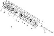
- FIG. 1illustrates a Robotic Motor Drive and Haptic Feedback System 10 for use in a medical procedure, such as a Minimal Invasive Surgery (MIS).
- the systemuses precision actuators, eg, 12 and 22 , to move and induce tensile forces in a mechanical drive unit comprising cables and pulleys, eg, 18 and 20 , and which, in turn, transmit motion for articulating the robotic arm (not shown) and end effector assembly (not shown) connected to the robotic arm.
- An end effector assemblyis an assembly of medical tools/equipment as described above.
- the precision actuatorscan be linear actuators.
- the precision actuatorscan be motors.
- motor and actuatorhave been hereinafter used interchangeably.
- the system 10makes use of force transducers eg, 16 , to measure forces acting on the joints of the robotic arm and the end effector assembly and generate signals corresponding to the measured forces. Furthermore, the signals generated by the force transducers are transmitted to a robotic hand controller (not shown) where haptic force feedback, in the form of vibration and counterforces, is generated by motors (not shown) present in the exoskeleton of the robotic hand controller. The said force feedback thus assists the user to apply optimum pressure on the tissue and sutures.
- the force transducersare mounted on the same cable elements (shown in FIG. 2 ) that are used in the drive unit of the system 10 . The force transducers estimate the said forces by measuring tension loads acting on the cable elements.
- the operatorIn order to access different points within the site of surgery, the operator has to articulate the robotic arm, and has to position it accurately over the localization point, i.e., the site which needs to be operated on. Thereafter, the end effector assembly has to be positioned and oriented in space in a manner such that it gets proximal to the localization point.
- the robotic arms in the current state of the artare known to comprise joints. These joints can be moved to achieve the desired articulation of the robotic arm in the available X, Y and Z planes of a co-ordinate system.
- the joints and the elongated shaft like robotic armare as depicted in FIG. 5 .
- the end effectorsare capable of generating a pitch, yaw, roll and pincer action. Combining the motion of the robotic arm and the end effectors, motion in numerous degrees of freedom can be achieved.
- the positioning for reaching the exact area at the site of surgeryis done by actuating the first and second set of motors present in the joint drive assembly 24 and tool drive assembly 14 , respectively.
- the motorsin turn achieve the proper positioning by transmitting the motion through the cable elements (not shown) in the system, which are as described with the help of subsequent figures.
- the robotic arm jointsdescribed below with reference to FIGS. 2 and 5 , are driven with the help of one or more of the motors from the joint drive actuator assembly 24 which vary the tension in the cable element to drive the joints.
- the movement of the jointstakes the robotic arm proximal to the site of surgery. Hence, it can be said that the cable element controls the movement of the robotic arm.
- the driving of the robotic arm joints with the help of one or more motorsis achieved by performing a joint control procedure.
- the tension in the cable elements, passing through the jointsis decreased by moving the one or more motors from a high locking tension level (X) to another appropriate unlocking low tension level (Y) according to the intended motion.
- This procedureis called “unlocking” since this enables the joint cable elements to lower their inertia to be pulled easily in a certain direction.
- the one or motorsare further actuated and the robotic arm joint is moved to reach its desired position.
- the one or more motorsare actuated again to increase the tension in the cables from a Level Y to Level X in order to lock the assembly in that position.
- the lockingis desirable to provide a sturdy and stable platform to position the end effector to perform the surgical procedure.
- the tension level or the magnitude of tensile forces which needs to be induced in the cable elementsranges from a level X to a level Y and is a pre-determined value.
- software procedural algorithmscan be embedded in the system to automate numerous operations which the operator performs manually.
- Software procedural algorithmscan be used to replicate a given set of instructions similar to the joint control procedure described above to predict joint movements to ease the manoeuvring of the joints.
- the Software procedural algorithmsenable the different functionalities to be programmed and subsequently used to follow both planned and learned paths for auto-inserting and auto-retracting the end effector.
- the planned pathis the manual course of instruction as given by a user to move the end effector
- the learned path courseprovides the user with the ability to record the frequently used manoeuvres or actions and replay them while performing a surgical operation whenever a need arises.
- the learned path coursenot only eliminates the need of manual action and the possibility of any error associated thereof but also performs the operation quickly and efficiently.
- the learned pathenables auto-inserting and auto-retracting controls which remember the positions of all end effector and joint control movements performed manually by the user, and then enable the performance of the registered steps automatically.
- Software controlcan also remove the unnecessary steps or wait periods to further accelerate the auto-inserting and auto-retracting process.
- auto-retract and auto-insert controlssignify automatic retraction of one existing end effector out of the patient body and insertion of the next end effector into the body along the same path. It is also possible to embed software control algorithms to control a coordinated movement of multiple joints, and to monitor and control joint force. These algorithms can achieve this directly through force transducers present on the cable element for the joint, or indirectly through control of the motor winding current.
- an end effector control procedureis performed to move the end effector, with the help of one or more motors from the tool drive assembly 14 , to the operating point within the site of surgery.
- Thisis performed by pre-tensioning all end effector control cable elements by raising the force to a level (Z) and then moving the one or more motors to actuate the roll, pitch, yaw, open/close movements (pincer) of the end effector.
- the tension in the cableis increased to a level (A) to lock the end effector in that position.
- the levels Z and Aare similar to levels X and Y, respectively, of the joint control procedure, but can have a varying magnitude.
- Software procedural algorithmscan be embedded in the system to synchronize the pincer movements of various end effectors to create coupled pincer movement.
- a haptic force feedback signalis generated to provide the user a real feel of the forces acting at the site of surgery. This is accomplished by measuring the differential force between each end effector-cable element pair using the force transducers, e.g., 16.
- Software procedural algorithmscan be provided to map the forces measured by the force transducers to the real-time 3-dimensional model of the articulated robotic arm configuration. The compared output haptic force is thus resolved through a set of co-ordinate transformations and is filtered to provide a decoupled haptic feedback for the various degrees of freedom of the robotic arm assembly. The need for filtering the measured and mapped force signal is described in the following discussion.
- the cable elements used in the present inventionhave dual usage, i.e., to drive the robotic arm or the end effector and to achieve force transduction for the degree of freedom in question.
- the cable elementdrives the robotic arm
- inherent frictionarises from the mechanical sources present in the drive system 10 .
- Some mechanical sources presentare the guide pulleys and the cable elements themselves.
- frictionarises from the end effector tool—tissue interface.
- signal filter 15can be used in the system 10 to separate noise from the measured force signal.
- the signal filter 15is a band-pass filter.
- the signal filter 15is a high pass filter readily known to a person of ordinary skill in the art.
- the signal measured by the force transducersis given to a control system including the high-pass filter.
- the control systemaccepts an overall signal drift from the force transducer and provides only ‘spikes’ of signal change to the robotic hand controller by performing high-pass filtering.
- the high pass filterlets the high frequency present in the signal pass to the robotic hand controller and attenuates the low frequencies. Thereafter, the signal is fed to a haptics capable hand controller where it is interpreted and an accurate force feedback is given to the user.
- the compensations made for the frictional forcescan also be learned or predicted for a certain configuration of the articulating arm in a manner similar to the joint control procedure.
- the placement of the signal filter 15can be different from that shown in FIG. 1 .
- the signal filter 15can be external to the system 10 .
- a single cable elementis responsible for driving a robotic arm joint and the end effector associated with it. Further, the transducers are also mounted in connection to the same cable element and sense the force acting on it that acts as an input for generation of the haptic force feedback.
- a cable elementcan have one motor for tensioning and one motor to drive a pivoting arm that moves the cable element.
- the two independent motorslinear actuators
- the two independent motorscan then be electronically coupled through a precision drive system and software to synchronize their motions and dynamically adjust the cable element tensions.
- the dynamic tensioning of the cables during synchronized movementmay allow for improved haptics isolation from the static friction forces.
- each motor of the tool drive assembly 14 or the joint drive assembly 24can independently move and tension one cable element.
- the set of motorscan be completely replaced with passive springs which can tension the cable elements.
- haptic feedback resolutioncan be enhanced by providing minimum length conduit paths, minimal contact/friction points, PTFE or other low friction coatings on cables and conduits, and internal roller bearings at pulley guides. These features help to reduce the inherent friction caused by the environment and the mechanical assembly and thus make the force feedback more accurate.
- the method for transmitting motion from the motor drive to the robotic arm and the end effector, and sensing force feedback through the same cable elementis accomplished by using system 10 as shown in FIG. 1 which includes a plurality of triad units.
- the triad unitis formed by a linear actuator, a force transducer and a cable element.
- the Robotic Motor Drive and Haptic Feedback System 10 of FIG. 1includes two sets of linear actuators, the first set (represented by 24 ) for providing transmission to the robotic arm joints and the second set (represented by 14 ) for articulating the end effector.
- a single degree of freedom of movement of the robotic arm and the corresponding end effectorcan be achieved by actuating either or both of the first set of motors or/and the second set of motors. Further, each degree of freedom has a separate triad associated with it.
- a triad unit used for articulating the end effector in one of its degrees of freedom and sensing the forces associated with that degree of freedomis composed of an end effector actuator selected from a set of tool drive linear actuators, represented by 14 , a force transducer selected from a group of force transducers including 16 , and a cable element selected from a group of cable elements (not shown).
- the selected end effector actuatoris connected to the cable element to drive the end effector, as described earlier.
- the force transducer 16is also attached to the cable element.
- the cable elementis made to pass through the pulleys, such as 18 and 20 , into the middle of a guide tube 32 , and finally connects to the robotic arm and the end effector which it controls.
- the force transducer 16measures any environmental forces imparted on the end effector pertaining to the degree of freedom being controlled, converts the measured forces to a signal, and relays the signal to a robotic console where the user sits.
- An appropriate haptics capable hand unitconverts the signal received into vibrations and counter forces to provide the force feedback signal to the operator. Therefore, to drive each individual degree of freedom of the multiple degrees of freedom of a robotic arm, a separate triad unit is preferably present in the system. Hence, one or more such units are housed within the Robotic Motor Drive and Haptic Feedback System 10 depending on the total degree of freedom articulating capability of the robotic arm.
- a robotic arm actuator from the set of joint driving actuatorsrepresented by 24 .
- the robotic arm actuatorwill be connected to one of the force transducers e.g., 16 and a cable element passing through the cable clamp 26 to form a triad unit, and thus articulate, sense and measure force for haptic feedback as mentioned above in the case of the end effector assembly.
- the cable elementis made to pass through its corresponding pulleys, such as 28 and 30 , into the middle of the guide tube 32 , and then is connected to the robotic arm joint which it intends to control.
- the cone plate nose assembly 34may contain force transducers within the cone plate nose 34 to sense the forces acting in the translational planes X, Y, and Z of the robotic arm.
- the output signal from the force transducers present in the cone plate nose 34is passed to the control system for filtering any noise present. This process of filtering has been described above. It will be readily apparent to a person of ordinary skill in the art that force sensing, the placement of the transducers and joint articulation can be achieved by a method other than those described above.
- FIG. 2is a perspective view of the Robotic Motor Drive and Haptic Feedback System 10 illustrating one of the possible paths of the cable element through the various components of the system 10 .
- the cable element 48is a part of the triad unit which is described above.
- the cable element 48is shown to be connected to an end effector actuator 36 selected from a set of tool drive linear actuators 14 , and a force transducer 38 selected from a group of force transducers.
- the cable element 48is shown to be passing through the pulleys 40 and 42 which are selected from a group of pulleys, into the middle of the guide tube 44 , and to a corresponding robotic arm and end effector assembly, collectively represented by 46 , which are controlled by the triad unit of which the cable element 48 is a part.
- the principles corresponding to the articulation of the robotic arms and the end effectors and the sensing of forces acting at the end effectorhave been described in regard to FIG. 1 .
- FIG. 3illustrates a magnified view of area A depicted in FIG. 2 .
- FIG. 3depicts one of the possible arrangements of the cable element 48 inside the Robotic Motor Drive and Haptic Feedback System 10 .
- the cable element 48is shown to be connected to a force transducer 50 , and thereafter passing through two pulley arrangements 52 and 54 .
- FIG. 4illustrates magnified view of area B depicted in FIG. 2 .
- FIG. 5illustrates one of the possible arrangements of the cable element 48 inside the Robotic arm 56 of the Robotic Motor Drive and Haptic Feedback System 10 .
- the cable element 48is shown to be passing through the robotic arm 56 and connects to an end effector assembly 58 .
- the robotic arm 56is shown to have joints, represented by 60 while the end effector assembly is shown to have an end effector 62 .
- the motors used for the movement of the end effector and robotic arm jointsare the series 28000 , Size 11 Double Stack Linear Actuators from Haydon Switch & Instruments.
- the motors for the end effector movementuse the model 28M41-05-912, 5V DC, 0.42A per phase, 0.001′′ step, 1.25′′ stroke Linear Actuators. This motor provides excellent speed at moderate force levels.
- the motors for robotic arm joint movementuse the 28M47-05-910, 5V DC, 0.42A per phase, 0.000125′′ per step, 1′′ stroke Linear Actuators.
- the smaller step size versiongives much higher force for tensioning the joint cables at the expense of slower joint movement. Hence, joint control speed can be made slower than end effector control speed.
- the force transducers used in the system for force feedback signal generationare the Omega LCMFL-50N, Sub-miniature tension compression load cell.
- Omega LC201-50, Sub-miniature tension compression load cellis used for measuring force/tension levels on the joint cables and AL312BL, Sensotec Model 34 load cell is used in the form of three sensors arranged in a triangle to measure the force at the cone as described above.
- the shape and form of the motor drive and haptic feedback systemcan be obtained from several options. Further, details of cable placement, transducer placement, housing and arrangement of the motors and cables, and overall weight and dimensions can be changed on a case by case basis.
- the robotic motor drive and haptic feedback systemis mounted proximal to the robotic arm end effector assembly. In another embodiment, the system is at a remote location. In the latter case the length and routing of the joint and end effector control cables can be completely variable and can be changed accordingly.
- FIG. 6illustrates a flowchart of a method for operating a robotic manipulator assembly, in accordance with an embodiment of the present application.
- the method 64includes controlling a robotic manipulator assembly, such as one represented by system 10 , through a cable element, such as cable element 48 , for performing a medical procedure.
- the control procedureis as described for the figures above and is represented at step 66 .
- the methodfurther includes measuring the force imparted to the robotic manipulator assembly while it is performing the medical procedure.
- the forceis measured by using a set of transducers, such as transducers 16 and 38 , which along with an associated circuitry transform the measured force into a force feedback signal which is then transmitted to a user.
- the process of measuring the force and providing the force feedback signal to the useris as described for previous figures and is depicted at steps 68 and 70 .
- the present applicationenables the operator in accurately estimating the forces that are required for performing medical procedures, as the noise generated due to environmental factors is removed. This also helps in precise automation of the process, thereby saving a lot of time and effort. Further, the system makes use of a single cable element for transmitting and measuring forces imparted during the medical procedure. This simplifies the system and eliminates noise that is created by the use of multiple cables. In addition, the system can also be employed where a single cable element is required to control multiple units, such as a crane for lifting and holding multiple items.
Landscapes
- Engineering & Computer Science (AREA)
- Health & Medical Sciences (AREA)
- Life Sciences & Earth Sciences (AREA)
- Surgery (AREA)
- Robotics (AREA)
- Medical Informatics (AREA)
- Biomedical Technology (AREA)
- Heart & Thoracic Surgery (AREA)
- Nuclear Medicine, Radiotherapy & Molecular Imaging (AREA)
- Molecular Biology (AREA)
- Animal Behavior & Ethology (AREA)
- General Health & Medical Sciences (AREA)
- Public Health (AREA)
- Veterinary Medicine (AREA)
- Human Computer Interaction (AREA)
- Mechanical Engineering (AREA)
- Manipulator (AREA)
Abstract
Description
Claims (20)
Priority Applications (1)
| Application Number | Priority Date | Filing Date | Title |
|---|---|---|---|
| US12/655,675US8306656B1 (en) | 2009-01-12 | 2010-01-05 | Method and system for performing medical procedure |
Applications Claiming Priority (2)
| Application Number | Priority Date | Filing Date | Title |
|---|---|---|---|
| US20483809P | 2009-01-12 | 2009-01-12 | |
| US12/655,675US8306656B1 (en) | 2009-01-12 | 2010-01-05 | Method and system for performing medical procedure |
Publications (1)
| Publication Number | Publication Date |
|---|---|
| US8306656B1true US8306656B1 (en) | 2012-11-06 |
Family
ID=47075517
Family Applications (1)
| Application Number | Title | Priority Date | Filing Date |
|---|---|---|---|
| US12/655,675Active2031-02-26US8306656B1 (en) | 2009-01-12 | 2010-01-05 | Method and system for performing medical procedure |
Country Status (1)
| Country | Link |
|---|---|
| US (1) | US8306656B1 (en) |
Cited By (63)
| Publication number | Priority date | Publication date | Assignee | Title |
|---|---|---|---|---|
| US20120059392A1 (en)* | 2007-06-13 | 2012-03-08 | Intuitive Surgical Operations, Inc. | Method and system for moving a plurality of articulated instruments in tandem back towards an entry guide |
| US9232984B2 (en) | 1999-04-07 | 2016-01-12 | Intuitive Surgical Operations, Inc. | Real-time generation of three-dimensional ultrasound image using a two-dimensional ultrasound transducer in a robotic system |
| US9333042B2 (en) | 2007-06-13 | 2016-05-10 | Intuitive Surgical Operations, Inc. | Medical robotic system with coupled control modes |
| US9345387B2 (en) | 2006-06-13 | 2016-05-24 | Intuitive Surgical Operations, Inc. | Preventing instrument/tissue collisions |
| US9469034B2 (en) | 2007-06-13 | 2016-10-18 | Intuitive Surgical Operations, Inc. | Method and system for switching modes of a robotic system |
| US9492927B2 (en) | 2009-08-15 | 2016-11-15 | Intuitive Surgical Operations, Inc. | Application of force feedback on an input device to urge its operator to command an articulated instrument to a preferred pose |
| US9516996B2 (en) | 2008-06-27 | 2016-12-13 | Intuitive Surgical Operations, Inc. | Medical robotic system providing computer generated auxiliary views of a camera instrument for controlling the position and orienting of its tip |
| US9622826B2 (en) | 2010-02-12 | 2017-04-18 | Intuitive Surgical Operations, Inc. | Medical robotic system providing sensory feedback indicating a difference between a commanded state and a preferred pose of an articulated instrument |
| US9717563B2 (en) | 2008-06-27 | 2017-08-01 | Intuitive Surgical Operations, Inc. | Medical robotic system providing an auxilary view including range of motion limitations for articulatable instruments extending out of a distal end of an entry guide |
| US9718190B2 (en) | 2006-06-29 | 2017-08-01 | Intuitive Surgical Operations, Inc. | Tool position and identification indicator displayed in a boundary area of a computer display screen |
| US9788909B2 (en) | 2006-06-29 | 2017-10-17 | Intuitive Surgical Operations, Inc | Synthetic representation of a surgical instrument |
| US9789608B2 (en) | 2006-06-29 | 2017-10-17 | Intuitive Surgical Operations, Inc. | Synthetic representation of a surgical robot |
| US9956044B2 (en) | 2009-08-15 | 2018-05-01 | Intuitive Surgical Operations, Inc. | Controller assisted reconfiguration of an articulated instrument during movement into and out of an entry guide |
| US10008017B2 (en) | 2006-06-29 | 2018-06-26 | Intuitive Surgical Operations, Inc. | Rendering tool information as graphic overlays on displayed images of tools |
| CN108393922A (en)* | 2018-02-10 | 2018-08-14 | 合肥工业大学 | One kind having multivariant robotic tool finger and purposes |
| US10092359B2 (en) | 2010-10-11 | 2018-10-09 | Ecole Polytechnique Federale De Lausanne | Mechanical manipulator for surgical instruments |
| US20180297211A1 (en)* | 2008-08-22 | 2018-10-18 | Titan Medical Inc. | Robotic hand controller |
| US20190053862A1 (en)* | 2016-09-27 | 2019-02-21 | Brainlab Ag | Efficient positioning of a mechatronic arm |
| US10258425B2 (en) | 2008-06-27 | 2019-04-16 | Intuitive Surgical Operations, Inc. | Medical robotic system providing an auxiliary view of articulatable instruments extending out of a distal end of an entry guide |
| US10265129B2 (en) | 2014-02-03 | 2019-04-23 | Distalmotion Sa | Mechanical teleoperated device comprising an interchangeable distal instrument |
| US10325072B2 (en) | 2011-07-27 | 2019-06-18 | Ecole Polytechnique Federale De Lausanne (Epfl) | Mechanical teleoperated device for remote manipulation |
| US10357320B2 (en) | 2014-08-27 | 2019-07-23 | Distalmotion Sa | Surgical system for microsurgical techniques |
| US10363055B2 (en) | 2015-04-09 | 2019-07-30 | Distalmotion Sa | Articulated hand-held instrument |
| US10413374B2 (en) | 2018-02-07 | 2019-09-17 | Distalmotion Sa | Surgical robot systems comprising robotic telemanipulators and integrated laparoscopy |
| US10507066B2 (en) | 2013-02-15 | 2019-12-17 | Intuitive Surgical Operations, Inc. | Providing information of tools by filtering image areas adjacent to or on displayed images of the tools |
| US10548680B2 (en) | 2014-12-19 | 2020-02-04 | Distalmotion Sa | Articulated handle for mechanical telemanipulator |
| US10568709B2 (en) | 2015-04-09 | 2020-02-25 | Distalmotion Sa | Mechanical teleoperated device for remote manipulation |
| US10568707B2 (en) | 2008-08-22 | 2020-02-25 | Titan Medical Inc. | Robotic hand controller |
| EP3632360A1 (en)* | 2018-10-04 | 2020-04-08 | Biosense Webster (Israel) Ltd. | Automatic probe reinsertion |
| US10646294B2 (en) | 2014-12-19 | 2020-05-12 | Distalmotion Sa | Reusable surgical instrument for minimally invasive procedures |
| US10695138B2 (en) | 2013-08-15 | 2020-06-30 | Intuitive Surgical Operations, Inc. | Robotic instrument driven element |
| US10786272B2 (en) | 2015-08-28 | 2020-09-29 | Distalmotion Sa | Surgical instrument with increased actuation force |
| US10799303B2 (en) | 2013-08-15 | 2020-10-13 | Intuitive Surgical Operations, Inc. | Preloaded surgical instrument interface |
| US10864049B2 (en) | 2014-12-19 | 2020-12-15 | Distalmotion Sa | Docking system for mechanical telemanipulator |
| US10864052B2 (en) | 2014-12-19 | 2020-12-15 | Distalmotion Sa | Surgical instrument with articulated end-effector |
| US10932868B2 (en) | 2013-08-15 | 2021-03-02 | Intuitive Surgical Operations, Inc. | Variable instrument preload mechanism controller |
| US10960182B2 (en) | 2016-02-05 | 2021-03-30 | Board Of Regents Of The University Of Texas System | Steerable intra-luminal medical device |
| US10993773B2 (en) | 2013-08-15 | 2021-05-04 | Intuitive Surgical Operations, Inc. | Instrument sterile adapter drive features |
| US11007641B2 (en) | 2017-07-17 | 2021-05-18 | Canon U.S.A., Inc. | Continuum robot control methods and apparatus |
| US11039820B2 (en) | 2014-12-19 | 2021-06-22 | Distalmotion Sa | Sterile interface for articulated surgical instruments |
| US11058503B2 (en) | 2017-05-11 | 2021-07-13 | Distalmotion Sa | Translational instrument interface for surgical robot and surgical robot systems comprising the same |
| US11090124B2 (en) | 2013-08-15 | 2021-08-17 | Intuitive Surgical Operations, Inc. | Instrument sterile adapter drive interface |
| US11278366B2 (en) | 2017-04-27 | 2022-03-22 | Canon U.S.A., Inc. | Method for controlling a flexible manipulator |
| US20220105639A1 (en)* | 2020-10-05 | 2022-04-07 | Verb Surgical Inc. | Null space control for end effector joints of a robotic instrument |
| WO2022088537A1 (en)* | 2020-10-29 | 2022-05-05 | 北京唯迈医疗设备有限公司 | Interventional surgical robot guide wire friction feedback device and method |
| US11432894B2 (en) | 2017-11-15 | 2022-09-06 | Intuitive Surgical Operations, Inc. | Surgical instrument end effector with integral FBG |
| US11504144B2 (en) | 2016-02-05 | 2022-11-22 | Board Of Regents Of The University Of Texas System | Surgical apparatus |
| US11571264B2 (en) | 2007-12-18 | 2023-02-07 | Intuitive Surgical Operations, Inc. | Force sensor temperature compensation |
| US11650111B2 (en) | 2007-12-18 | 2023-05-16 | Intuitive Surgical Operations, Inc. | Ribbed force sensor |
| US11707335B2 (en) | 2005-12-30 | 2023-07-25 | Intuitive Surgical Operations, Inc. | Wireless force sensor on a distal portion of a surgical instrument and method |
| US11815412B2 (en) | 2018-11-15 | 2023-11-14 | Intuitive Surgical Operations, Inc. | Strain sensor with contoured deflection surface |
| US11844585B1 (en) | 2023-02-10 | 2023-12-19 | Distalmotion Sa | Surgical robotics systems and devices having a sterile restart, and methods thereof |
| US11980504B2 (en) | 2018-05-25 | 2024-05-14 | Intuitive Surgical Operations, Inc. | Fiber Bragg grating end effector force sensor |
| US12114945B2 (en) | 2021-09-13 | 2024-10-15 | Distalmotion Sa | Instruments for surgical robotic system and interfaces for the same |
| US12188838B2 (en) | 2019-09-17 | 2025-01-07 | Intuitive Surgical Operations, Inc. | Compact, differential, coaxial inductive force sensor |
| US12239396B2 (en) | 2008-06-27 | 2025-03-04 | Intuitive Surgical Operations, Inc. | Medical robotic system providing an auxiliary view including range of motion limitations for articulatable instruments extending out of a distal end of an entry guide |
| US12239393B2 (en) | 2020-05-18 | 2025-03-04 | Intuitive Surgical Operations, Inc. | Hard stop that produces a reactive moment upon engagement for cantilever-based force sensing |
| US12257014B2 (en) | 2021-06-22 | 2025-03-25 | Intuitive Surgical Operations, Inc. | Devices and methods for crimp interface for cable tension sensor |
| US12266040B2 (en) | 2009-03-31 | 2025-04-01 | Intuitive Surgical Operations, Inc. | Rendering tool information as graphic overlays on displayed images of tools |
| US12357400B2 (en) | 2006-06-29 | 2025-07-15 | Intuitive Surgical Operations, Inc. | Synthetic representation of a surgical robot |
| US12376927B2 (en) | 2018-02-07 | 2025-08-05 | Distalmotion Sa | Surgical robot systems comprising robotic telemanipulators and integrated laparoscopy |
| US12390291B2 (en) | 2018-11-15 | 2025-08-19 | Intuitive Surgical Operations, Inc. | Decoupling tool shaft from cable drive load |
| US12402960B2 (en) | 2010-10-11 | 2025-09-02 | Ecole Polytechnique Federale De Lausanne (Epfl) | Mechanical manipulator for surgical instruments |
Citations (3)
| Publication number | Priority date | Publication date | Assignee | Title |
|---|---|---|---|---|
| US20040111183A1 (en) | 2002-08-13 | 2004-06-10 | Sutherland Garnette Roy | Microsurgical robot system |
| US20040116906A1 (en) | 2002-12-17 | 2004-06-17 | Kenneth Lipow | Method and apparatus for controlling a surgical robot to mimic, harmonize and enhance the natural neurophysiological behavior of a surgeon |
| US7453227B2 (en)* | 2005-12-20 | 2008-11-18 | Intuitive Surgical, Inc. | Medical robotic system with sliding mode control |
- 2010
- 2010-01-05USUS12/655,675patent/US8306656B1/enactiveActive
Patent Citations (4)
| Publication number | Priority date | Publication date | Assignee | Title |
|---|---|---|---|---|
| US20040111183A1 (en) | 2002-08-13 | 2004-06-10 | Sutherland Garnette Roy | Microsurgical robot system |
| US20100063630A1 (en) | 2002-08-13 | 2010-03-11 | Garnette Roy Sutherland | Microsurgical robot system |
| US20040116906A1 (en) | 2002-12-17 | 2004-06-17 | Kenneth Lipow | Method and apparatus for controlling a surgical robot to mimic, harmonize and enhance the natural neurophysiological behavior of a surgeon |
| US7453227B2 (en)* | 2005-12-20 | 2008-11-18 | Intuitive Surgical, Inc. | Medical robotic system with sliding mode control |
Cited By (136)
| Publication number | Priority date | Publication date | Assignee | Title |
|---|---|---|---|---|
| US10271909B2 (en) | 1999-04-07 | 2019-04-30 | Intuitive Surgical Operations, Inc. | Display of computer generated image of an out-of-view portion of a medical device adjacent a real-time image of an in-view portion of the medical device |
| US9232984B2 (en) | 1999-04-07 | 2016-01-12 | Intuitive Surgical Operations, Inc. | Real-time generation of three-dimensional ultrasound image using a two-dimensional ultrasound transducer in a robotic system |
| US10433919B2 (en) | 1999-04-07 | 2019-10-08 | Intuitive Surgical Operations, Inc. | Non-force reflecting method for providing tool force information to a user of a telesurgical system |
| US11707335B2 (en) | 2005-12-30 | 2023-07-25 | Intuitive Surgical Operations, Inc. | Wireless force sensor on a distal portion of a surgical instrument and method |
| US9345387B2 (en) | 2006-06-13 | 2016-05-24 | Intuitive Surgical Operations, Inc. | Preventing instrument/tissue collisions |
| US10137575B2 (en) | 2006-06-29 | 2018-11-27 | Intuitive Surgical Operations, Inc. | Synthetic representation of a surgical robot |
| US12357400B2 (en) | 2006-06-29 | 2025-07-15 | Intuitive Surgical Operations, Inc. | Synthetic representation of a surgical robot |
| US11638999B2 (en) | 2006-06-29 | 2023-05-02 | Intuitive Surgical Operations, Inc. | Synthetic representation of a surgical robot |
| US10773388B2 (en) | 2006-06-29 | 2020-09-15 | Intuitive Surgical Operations, Inc. | Tool position and identification indicator displayed in a boundary area of a computer display screen |
| US11865729B2 (en) | 2006-06-29 | 2024-01-09 | Intuitive Surgical Operations, Inc. | Tool position and identification indicator displayed in a boundary area of a computer display screen |
| US10737394B2 (en) | 2006-06-29 | 2020-08-11 | Intuitive Surgical Operations, Inc. | Synthetic representation of a surgical robot |
| US9718190B2 (en) | 2006-06-29 | 2017-08-01 | Intuitive Surgical Operations, Inc. | Tool position and identification indicator displayed in a boundary area of a computer display screen |
| US9788909B2 (en) | 2006-06-29 | 2017-10-17 | Intuitive Surgical Operations, Inc | Synthetic representation of a surgical instrument |
| US9789608B2 (en) | 2006-06-29 | 2017-10-17 | Intuitive Surgical Operations, Inc. | Synthetic representation of a surgical robot |
| US9801690B2 (en) | 2006-06-29 | 2017-10-31 | Intuitive Surgical Operations, Inc. | Synthetic representation of a surgical instrument |
| US10008017B2 (en) | 2006-06-29 | 2018-06-26 | Intuitive Surgical Operations, Inc. | Rendering tool information as graphic overlays on displayed images of tools |
| US10730187B2 (en) | 2006-06-29 | 2020-08-04 | Intuitive Surgical Operations, Inc. | Tool position and identification indicator displayed in a boundary area of a computer display screen |
| US10695136B2 (en) | 2007-06-13 | 2020-06-30 | Intuitive Surgical Operations, Inc. | Preventing instrument/tissue collisions |
| US11751955B2 (en) | 2007-06-13 | 2023-09-12 | Intuitive Surgical Operations, Inc. | Method and system for retracting an instrument into an entry guide |
| US12295681B2 (en) | 2007-06-13 | 2025-05-13 | Intuitive Surgical Operations, Inc. | Method and system for retracting an instrument into an entry guide |
| US11432888B2 (en) | 2007-06-13 | 2022-09-06 | Intuitive Surgical Operations, Inc. | Method and system for moving a plurality of articulated instruments in tandem back towards an entry guide |
| US9629520B2 (en) | 2007-06-13 | 2017-04-25 | Intuitive Surgical Operations, Inc. | Method and system for moving an articulated instrument back towards an entry guide while automatically reconfiguring the articulated instrument for retraction into the entry guide |
| US10188472B2 (en) | 2007-06-13 | 2019-01-29 | Intuitive Surgical Operations, Inc. | Medical robotic system with coupled control modes |
| US9469034B2 (en) | 2007-06-13 | 2016-10-18 | Intuitive Surgical Operations, Inc. | Method and system for switching modes of a robotic system |
| US9901408B2 (en) | 2007-06-13 | 2018-02-27 | Intuitive Surgical Operations, Inc. | Preventing instrument/tissue collisions |
| US20120059392A1 (en)* | 2007-06-13 | 2012-03-08 | Intuitive Surgical Operations, Inc. | Method and system for moving a plurality of articulated instruments in tandem back towards an entry guide |
| US9333042B2 (en) | 2007-06-13 | 2016-05-10 | Intuitive Surgical Operations, Inc. | Medical robotic system with coupled control modes |
| US9138129B2 (en)* | 2007-06-13 | 2015-09-22 | Intuitive Surgical Operations, Inc. | Method and system for moving a plurality of articulated instruments in tandem back towards an entry guide |
| US10271912B2 (en) | 2007-06-13 | 2019-04-30 | Intuitive Surgical Operations, Inc. | Method and system for moving a plurality of articulated instruments in tandem back towards an entry guide |
| US11399908B2 (en) | 2007-06-13 | 2022-08-02 | Intuitive Surgical Operations, Inc. | Medical robotic system with coupled control modes |
| US12097002B2 (en) | 2007-06-13 | 2024-09-24 | Intuitive Surgical Operations, Inc. | Medical robotic system with coupled control modes |
| US11571264B2 (en) | 2007-12-18 | 2023-02-07 | Intuitive Surgical Operations, Inc. | Force sensor temperature compensation |
| US11650111B2 (en) | 2007-12-18 | 2023-05-16 | Intuitive Surgical Operations, Inc. | Ribbed force sensor |
| US10368952B2 (en) | 2008-06-27 | 2019-08-06 | Intuitive Surgical Operations, Inc. | Medical robotic system providing an auxiliary view including range of motion limitations for articulatable instruments extending out of a distal end of an entry guide |
| US9717563B2 (en) | 2008-06-27 | 2017-08-01 | Intuitive Surgical Operations, Inc. | Medical robotic system providing an auxilary view including range of motion limitations for articulatable instruments extending out of a distal end of an entry guide |
| US9516996B2 (en) | 2008-06-27 | 2016-12-13 | Intuitive Surgical Operations, Inc. | Medical robotic system providing computer generated auxiliary views of a camera instrument for controlling the position and orienting of its tip |
| US11382702B2 (en) | 2008-06-27 | 2022-07-12 | Intuitive Surgical Operations, Inc. | Medical robotic system providing an auxiliary view including range of motion limitations for articulatable instruments extending out of a distal end of an entry guide |
| US12239396B2 (en) | 2008-06-27 | 2025-03-04 | Intuitive Surgical Operations, Inc. | Medical robotic system providing an auxiliary view including range of motion limitations for articulatable instruments extending out of a distal end of an entry guide |
| US10258425B2 (en) | 2008-06-27 | 2019-04-16 | Intuitive Surgical Operations, Inc. | Medical robotic system providing an auxiliary view of articulatable instruments extending out of a distal end of an entry guide |
| US11638622B2 (en) | 2008-06-27 | 2023-05-02 | Intuitive Surgical Operations, Inc. | Medical robotic system providing an auxiliary view of articulatable instruments extending out of a distal end of an entry guide |
| US11166771B2 (en) | 2008-08-22 | 2021-11-09 | Titan Medical Inc. | Robotic hand controller |
| US11266471B2 (en) | 2008-08-22 | 2022-03-08 | Titan Medical Inc. | Robotic hand controller |
| US10568707B2 (en) | 2008-08-22 | 2020-02-25 | Titan Medical Inc. | Robotic hand controller |
| US10532466B2 (en)* | 2008-08-22 | 2020-01-14 | Titan Medical Inc. | Robotic hand controller |
| US11737838B2 (en) | 2008-08-22 | 2023-08-29 | Titan Medical Inc. | Robotic hand controller |
| US20180297211A1 (en)* | 2008-08-22 | 2018-10-18 | Titan Medical Inc. | Robotic hand controller |
| US10993774B2 (en) | 2008-08-22 | 2021-05-04 | Titan Medical Inc. | Robotic hand controller |
| US12266040B2 (en) | 2009-03-31 | 2025-04-01 | Intuitive Surgical Operations, Inc. | Rendering tool information as graphic overlays on displayed images of tools |
| US11941734B2 (en) | 2009-03-31 | 2024-03-26 | Intuitive Surgical Operations, Inc. | Rendering tool information as graphic overlays on displayed images of tools |
| US10984567B2 (en) | 2009-03-31 | 2021-04-20 | Intuitive Surgical Operations, Inc. | Rendering tool information as graphic overlays on displayed images of tools |
| US10282881B2 (en) | 2009-03-31 | 2019-05-07 | Intuitive Surgical Operations, Inc. | Rendering tool information as graphic overlays on displayed images of tools |
| US9956044B2 (en) | 2009-08-15 | 2018-05-01 | Intuitive Surgical Operations, Inc. | Controller assisted reconfiguration of an articulated instrument during movement into and out of an entry guide |
| US10772689B2 (en) | 2009-08-15 | 2020-09-15 | Intuitive Surgical Operations, Inc. | Controller assisted reconfiguration of an articulated instrument during movement into and out of an entry guide |
| US11596490B2 (en) | 2009-08-15 | 2023-03-07 | Intuitive Surgical Operations, Inc. | Application of force feedback on an input device to urge its operator to command an articulated instrument to a preferred pose |
| US10271915B2 (en) | 2009-08-15 | 2019-04-30 | Intuitive Surgical Operations, Inc. | Application of force feedback on an input device to urge its operator to command an articulated instrument to a preferred pose |
| US9492927B2 (en) | 2009-08-15 | 2016-11-15 | Intuitive Surgical Operations, Inc. | Application of force feedback on an input device to urge its operator to command an articulated instrument to a preferred pose |
| US10959798B2 (en) | 2009-08-15 | 2021-03-30 | Intuitive Surgical Operations, Inc. | Application of force feedback on an input device to urge its operator to command an articulated instrument to a preferred pose |
| US9622826B2 (en) | 2010-02-12 | 2017-04-18 | Intuitive Surgical Operations, Inc. | Medical robotic system providing sensory feedback indicating a difference between a commanded state and a preferred pose of an articulated instrument |
| US10828774B2 (en) | 2010-02-12 | 2020-11-10 | Intuitive Surgical Operations, Inc. | Medical robotic system providing sensory feedback indicating a difference between a commanded state and a preferred pose of an articulated instrument |
| US10537994B2 (en) | 2010-02-12 | 2020-01-21 | Intuitive Surgical Operations, Inc. | Medical robotic system providing sensory feedback indicating a difference between a commanded state and a preferred pose of an articulated instrument |
| US11076922B2 (en) | 2010-10-11 | 2021-08-03 | Ecole Polytechnique Federale De Lausanne (Epfl) | Mechanical manipulator for surgical instruments |
| US12402960B2 (en) | 2010-10-11 | 2025-09-02 | Ecole Polytechnique Federale De Lausanne (Epfl) | Mechanical manipulator for surgical instruments |
| US10092359B2 (en) | 2010-10-11 | 2018-10-09 | Ecole Polytechnique Federale De Lausanne | Mechanical manipulator for surgical instruments |
| US10510447B2 (en) | 2011-07-27 | 2019-12-17 | Ecole Polytechnique Federale De Lausanne (Epfl) | Surgical teleoperated device for remote manipulation |
| US11200980B2 (en) | 2011-07-27 | 2021-12-14 | Ecole Polytechnique Federale De Lausanne (Epfl) | Surgical teleoperated device for remote manipulation |
| US10325072B2 (en) | 2011-07-27 | 2019-06-18 | Ecole Polytechnique Federale De Lausanne (Epfl) | Mechanical teleoperated device for remote manipulation |
| US11806102B2 (en) | 2013-02-15 | 2023-11-07 | Intuitive Surgical Operations, Inc. | Providing information of tools by filtering image areas adjacent to or on displayed images of the tools |
| US11389255B2 (en) | 2013-02-15 | 2022-07-19 | Intuitive Surgical Operations, Inc. | Providing information of tools by filtering image areas adjacent to or on displayed images of the tools |
| US10507066B2 (en) | 2013-02-15 | 2019-12-17 | Intuitive Surgical Operations, Inc. | Providing information of tools by filtering image areas adjacent to or on displayed images of the tools |
| US10932868B2 (en) | 2013-08-15 | 2021-03-02 | Intuitive Surgical Operations, Inc. | Variable instrument preload mechanism controller |
| EP3033030B1 (en)* | 2013-08-15 | 2020-07-22 | Intuitive Surgical Operations, Inc. | Robotic instrument driven element |
| US11090124B2 (en) | 2013-08-15 | 2021-08-17 | Intuitive Surgical Operations, Inc. | Instrument sterile adapter drive interface |
| US10993773B2 (en) | 2013-08-15 | 2021-05-04 | Intuitive Surgical Operations, Inc. | Instrument sterile adapter drive features |
| US10993775B2 (en) | 2013-08-15 | 2021-05-04 | Intuitive Surgical Operations, Inc. | Robotic instrument driven element |
| US10695138B2 (en) | 2013-08-15 | 2020-06-30 | Intuitive Surgical Operations, Inc. | Robotic instrument driven element |
| US11564758B2 (en) | 2013-08-15 | 2023-01-31 | Intuitive Surgical Operations, Inc. | Preloaded surgical instrument interface |
| US12220190B2 (en) | 2013-08-15 | 2025-02-11 | Intuitive Surgical Operations, Inc. | Preloaded surgical instrument interface |
| US10799303B2 (en) | 2013-08-15 | 2020-10-13 | Intuitive Surgical Operations, Inc. | Preloaded surgical instrument interface |
| US11793587B2 (en) | 2013-08-15 | 2023-10-24 | Intuitive Surgical Operations, Inc. | Preloaded surgical instrument interface |
| US10265129B2 (en) | 2014-02-03 | 2019-04-23 | Distalmotion Sa | Mechanical teleoperated device comprising an interchangeable distal instrument |
| US12329481B2 (en) | 2014-02-03 | 2025-06-17 | Distalmotion Sa | Mechanical teleoperated device comprising an interchangeable distal instrument |
| US10357320B2 (en) | 2014-08-27 | 2019-07-23 | Distalmotion Sa | Surgical system for microsurgical techniques |
| US11571195B2 (en) | 2014-12-19 | 2023-02-07 | Distalmotion Sa | Sterile interface for articulated surgical instruments |
| US11039820B2 (en) | 2014-12-19 | 2021-06-22 | Distalmotion Sa | Sterile interface for articulated surgical instruments |
| US11478315B2 (en) | 2014-12-19 | 2022-10-25 | Distalmotion Sa | Reusable surgical instrument for minimally invasive procedures |
| US12262880B2 (en) | 2014-12-19 | 2025-04-01 | Distalmotion Sa | Sterile interface for articulated surgical instruments |
| US10548680B2 (en) | 2014-12-19 | 2020-02-04 | Distalmotion Sa | Articulated handle for mechanical telemanipulator |
| US12262969B2 (en) | 2014-12-19 | 2025-04-01 | Distalmotion Sa | Reusable surgical instrument for minimally invasive procedures |
| US10646294B2 (en) | 2014-12-19 | 2020-05-12 | Distalmotion Sa | Reusable surgical instrument for minimally invasive procedures |
| US10864052B2 (en) | 2014-12-19 | 2020-12-15 | Distalmotion Sa | Surgical instrument with articulated end-effector |
| US10864049B2 (en) | 2014-12-19 | 2020-12-15 | Distalmotion Sa | Docking system for mechanical telemanipulator |
| US10363055B2 (en) | 2015-04-09 | 2019-07-30 | Distalmotion Sa | Articulated hand-held instrument |
| US10568709B2 (en) | 2015-04-09 | 2020-02-25 | Distalmotion Sa | Mechanical teleoperated device for remote manipulation |
| US11944337B2 (en) | 2015-08-28 | 2024-04-02 | Distalmotion Sa | Surgical instrument with increased actuation force |
| US10786272B2 (en) | 2015-08-28 | 2020-09-29 | Distalmotion Sa | Surgical instrument with increased actuation force |
| US11337716B2 (en) | 2015-08-28 | 2022-05-24 | Distalmotion Sa | Surgical instrument with increased actuation force |
| US12207834B2 (en) | 2016-02-05 | 2025-01-28 | Board Of Regents Of The University Of Texas System | Surgical apparatus |
| US11607238B2 (en) | 2016-02-05 | 2023-03-21 | Board Of Regents Of The University Of Texas System | Surgical apparatus |
| US10960182B2 (en) | 2016-02-05 | 2021-03-30 | Board Of Regents Of The University Of Texas System | Steerable intra-luminal medical device |
| US12369934B2 (en) | 2016-02-05 | 2025-07-29 | Board Of Regents Of The University Of Texas System | Surgical apparatus |
| US11504144B2 (en) | 2016-02-05 | 2022-11-22 | Board Of Regents Of The University Of Texas System | Surgical apparatus |
| US11918766B2 (en) | 2016-02-05 | 2024-03-05 | Board Of Regents Of The University Of Texas System | Steerable intra-luminal medical device |
| US11850378B2 (en) | 2016-02-05 | 2023-12-26 | Board Of Regents Of The University Of Texas System | Steerable intra-luminal medical device |
| US20230293248A1 (en)* | 2016-09-27 | 2023-09-21 | Brainlab Ag | Efficient positioning of a mechatronic arm |
| US11642182B2 (en)* | 2016-09-27 | 2023-05-09 | Brainlab Ag | Efficient positioning of a mechatronic arm |
| US20190053862A1 (en)* | 2016-09-27 | 2019-02-21 | Brainlab Ag | Efficient positioning of a mechatronic arm |
| US12114944B2 (en)* | 2016-09-27 | 2024-10-15 | Brainlab Ag | Efficient positioning of a mechatronic arm |
| US11278366B2 (en) | 2017-04-27 | 2022-03-22 | Canon U.S.A., Inc. | Method for controlling a flexible manipulator |
| US12295688B2 (en) | 2017-05-11 | 2025-05-13 | Distalmotion Sa | Translational instrument interface for surgical robot and surgical robot systems comprising the same |
| US11058503B2 (en) | 2017-05-11 | 2021-07-13 | Distalmotion Sa | Translational instrument interface for surgical robot and surgical robot systems comprising the same |
| US12262968B2 (en) | 2017-05-11 | 2025-04-01 | Distalmotion Sa | Translational instrument interface for surgical robot and surgical robot systems comprising the same |
| US11007641B2 (en) | 2017-07-17 | 2021-05-18 | Canon U.S.A., Inc. | Continuum robot control methods and apparatus |
| US11432894B2 (en) | 2017-11-15 | 2022-09-06 | Intuitive Surgical Operations, Inc. | Surgical instrument end effector with integral FBG |
| US11510745B2 (en) | 2018-02-07 | 2022-11-29 | Distalmotion Sa | Surgical robot systems comprising robotic telemanipulators and integrated laparoscopy |
| US12161438B2 (en) | 2018-02-07 | 2024-12-10 | Distalmotion Sa | Surgical robot systems comprising robotic telemanipulators and integrated laparoscopy |
| US10413374B2 (en) | 2018-02-07 | 2019-09-17 | Distalmotion Sa | Surgical robot systems comprising robotic telemanipulators and integrated laparoscopy |
| US12290328B2 (en) | 2018-02-07 | 2025-05-06 | Distalmotion Sa | Surgical robot systems comprising robotic telemanipulators and integrated laparoscopy |
| US12376927B2 (en) | 2018-02-07 | 2025-08-05 | Distalmotion Sa | Surgical robot systems comprising robotic telemanipulators and integrated laparoscopy |
| CN108393922A (en)* | 2018-02-10 | 2018-08-14 | 合肥工业大学 | One kind having multivariant robotic tool finger and purposes |
| US11980504B2 (en) | 2018-05-25 | 2024-05-14 | Intuitive Surgical Operations, Inc. | Fiber Bragg grating end effector force sensor |
| US11707179B2 (en) | 2018-10-04 | 2023-07-25 | Biosense Webster (Israel) Ltd. | Automatic probe reinsertion |
| EP3632360A1 (en)* | 2018-10-04 | 2020-04-08 | Biosense Webster (Israel) Ltd. | Automatic probe reinsertion |
| US11229492B2 (en) | 2018-10-04 | 2022-01-25 | Biosense Webster (Israel) Ltd. | Automatic probe reinsertion |
| US11815412B2 (en) | 2018-11-15 | 2023-11-14 | Intuitive Surgical Operations, Inc. | Strain sensor with contoured deflection surface |
| US12390291B2 (en) | 2018-11-15 | 2025-08-19 | Intuitive Surgical Operations, Inc. | Decoupling tool shaft from cable drive load |
| US12188838B2 (en) | 2019-09-17 | 2025-01-07 | Intuitive Surgical Operations, Inc. | Compact, differential, coaxial inductive force sensor |
| US12239393B2 (en) | 2020-05-18 | 2025-03-04 | Intuitive Surgical Operations, Inc. | Hard stop that produces a reactive moment upon engagement for cantilever-based force sensing |
| US20220105639A1 (en)* | 2020-10-05 | 2022-04-07 | Verb Surgical Inc. | Null space control for end effector joints of a robotic instrument |
| US12017369B2 (en)* | 2020-10-05 | 2024-06-25 | Verb Surgical Inc. | Null space control for end effector joints of a robotic instrument |
| WO2022088537A1 (en)* | 2020-10-29 | 2022-05-05 | 北京唯迈医疗设备有限公司 | Interventional surgical robot guide wire friction feedback device and method |
| US12257014B2 (en) | 2021-06-22 | 2025-03-25 | Intuitive Surgical Operations, Inc. | Devices and methods for crimp interface for cable tension sensor |
| US12114945B2 (en) | 2021-09-13 | 2024-10-15 | Distalmotion Sa | Instruments for surgical robotic system and interfaces for the same |
| US11844585B1 (en) | 2023-02-10 | 2023-12-19 | Distalmotion Sa | Surgical robotics systems and devices having a sterile restart, and methods thereof |
| US12349998B2 (en) | 2023-02-10 | 2025-07-08 | Distalmotion Sa | Surgical robotics systems and devices having a sterile restart, and methods thereof |
| US12089908B2 (en) | 2023-02-10 | 2024-09-17 | Distalmotion Sa | Surgical robotics systems and devices having a sterile restart, and methods thereof |
| US12082899B2 (en) | 2023-02-10 | 2024-09-10 | Distalmotion Sa | Surgical robotics systems and devices having a sterile restart, and methods thereof |
Similar Documents
| Publication | Publication Date | Title |
|---|---|---|
| US8306656B1 (en) | Method and system for performing medical procedure | |
| US20230218354A1 (en) | Surgery supporting apparatus for controlling motion of robot arm | |
| KR102222651B1 (en) | Systems and methods for controlling robot manipulators or associated tools | |
| Seibold et al. | Prototype of instrument for minimally invasive surgery with 6-axis force sensing capability | |
| US20190094084A1 (en) | Fluid pressure based end effector force transducer | |
| US12343104B2 (en) | Surgical platform supported and controlled by multiple arms | |
| JP6562174B1 (en) | Surgery support device | |
| KR20230058117A (en) | Control of Surgical Instruments with Backlash, Friction, and Compliance Under External Load in a Surgical Robotic System | |
| JP2020065904A (en) | Surgery support device | |
| van den Bedem et al. | Design of a minimally invasive surgical teleoperated master-slave system with haptic feedback | |
| Morel et al. | Comanipulation | |
| Peine et al. | Effect of backlash on surgical robotic task proficiency | |
| US20240173856A1 (en) | Systems and methods for controlling a robotic manipulator or associated tool | |
| WO2024226481A1 (en) | System and method for controlled ultrasonic sealing and cutting | |
| Toombs | The design and fabrication of a meso scale minimally invasive surgical robot |
Legal Events
| Date | Code | Title | Description |
|---|---|---|---|
| AS | Assignment | Owner name:TITAN MEDICAL INC., CANADA Free format text:ASSIGNMENT OF ASSIGNORS INTEREST;ASSIGNORS:SCHAIBLE, UWE;VELTRI, JEFF;AHMADI, AMIN;REEL/FRAME:023781/0080 Effective date:20100104 | |
| STCF | Information on status: patent grant | Free format text:PATENTED CASE | |
| FPAY | Fee payment | Year of fee payment:4 | |
| MAFP | Maintenance fee payment | Free format text:PAYMENT OF MAINTENANCE FEE, 8TH YR, SMALL ENTITY (ORIGINAL EVENT CODE: M2552); ENTITY STATUS OF PATENT OWNER: SMALL ENTITY Year of fee payment:8 | |
| AS | Assignment | Owner name:CORPORATION SERVICE COMPANY C/O PROJECT TIME LLC, DELAWARE Free format text:SECURITY INTEREST;ASSIGNOR:TITAN MEDICAL INC.;REEL/FRAME:052643/0922 Effective date:20200508 | |
| AS | Assignment | Owner name:TITAN MEDICAL INC., CANADA Free format text:RELEASE BY SECURED PARTY;ASSIGNOR:PROJECT TIME LLC;REEL/FRAME:059174/0081 Effective date:20220131 | |
| MAFP | Maintenance fee payment | Free format text:PAYMENT OF MAINTENANCE FEE, 12TH YR, SMALL ENTITY (ORIGINAL EVENT CODE: M2553); ENTITY STATUS OF PATENT OWNER: SMALL ENTITY Year of fee payment:12 |