US8306563B2 - Method and apparatus for muting a digital link in a distributed antenna system - Google Patents
Method and apparatus for muting a digital link in a distributed antenna systemDownload PDFInfo
- Publication number
- US8306563B2 US8306563B2US12/643,116US64311609AUS8306563B2US 8306563 B2US8306563 B2US 8306563B2US 64311609 AUS64311609 AUS 64311609AUS 8306563 B2US8306563 B2US 8306563B2
- Authority
- US
- United States
- Prior art keywords
- muting
- signal
- path
- mute
- controller
- Prior art date
- Legal status (The legal status is an assumption and is not a legal conclusion. Google has not performed a legal analysis and makes no representation as to the accuracy of the status listed.)
- Expired - Fee Related, expires
Links
Images


Classifications
- H—ELECTRICITY
- H04—ELECTRIC COMMUNICATION TECHNIQUE
- H04W—WIRELESS COMMUNICATION NETWORKS
- H04W52/00—Power management, e.g. Transmission Power Control [TPC] or power classes
- H04W52/04—Transmission power control [TPC]
- H04W52/30—Transmission power control [TPC] using constraints in the total amount of available transmission power
- H04W52/34—TPC management, i.e. sharing limited amount of power among users or channels or data types, e.g. cell loading
- H04W52/343—TPC management, i.e. sharing limited amount of power among users or channels or data types, e.g. cell loading taking into account loading or congestion level
- H—ELECTRICITY
- H04—ELECTRIC COMMUNICATION TECHNIQUE
- H04W—WIRELESS COMMUNICATION NETWORKS
- H04W52/00—Power management, e.g. Transmission Power Control [TPC] or power classes
- H04W52/04—Transmission power control [TPC]
- H04W52/38—TPC being performed in particular situations
- H04W52/386—TPC being performed in particular situations centralized, e.g. when the radio network controller or equivalent takes part in the power control
Definitions
- a Distributed Antenna Systemis a network of spatially separated antenna nodes connected to a common node via a transport medium that provides wireless service within a geographic area or structure.
- Common wireless communication system configurationsemploy a host unit as the common node, which is located at a centralized location (for example, at a facility that is controlled by a wireless service provider).
- the antenna nodes and related broadcasting and receiving equipment, located at a location that is remote from the host unitare also referred to as “remote units.”
- Radio frequency (RF) signalsare communicated between the host unit and one or more remote units.
- the host unitis typically communicatively coupled to one or more base stations (for example, via wired connection or via wireless connection) which allow bidirectional communications between wireless subscriber units within the DAS service area and communication networks such as, but not limited to, cellular phone networks, the public switch telephone network (PSTN) and the Internet.
- base stationsfor example, via wired connection or via wireless connection
- PSTNpublic switch telephone network
- a DAScan provide, by its nature, an infrastructure within a community that can scatter remote units across a geographic area for providing wireless services across that area.
- a DAS having a digital transport for the downlink and uplink transport signals sent between the host unit and the remote unitshas many advantages over a DAS having an analog transport. Digitizing the downlink and uplink RF signals, however, may introduce unwanted effects into the RF signal.
- a device for processing signals a distributed antenna systemcomprises: a first signal path for transporting digital data signals; a controller for monitoring events affecting the first signal path; and a muting module coupled to the controller, wherein the muting module controls muting of a signal power of the first signal path as directed by the controller.
- the muting moduleapplies a hard clamping to mute the signal power of the first signal path when the controller identifies an unplanned event.
- the muting moduleapplies a ramp to mute the signal power of the first signal path when the controller identified a planned event.
- FIG. 1is a block diagram of one embodiment of a distributed antenna system (DAS) including a host unit and a plurality of remote units;
- DASdistributed antenna system
- FIG. 2is a block diagram of one embodiment of a remote unit of FIG. 1 ;
- FIG. 3is a block diagram of one embodiment of a host unit of FIG. 1
- FIG. 4illustrates a schematic view of one embodiment of a DART module for using in either the host unit of FIG. 2 or the remote unit of FIG. 3 ;
- FIG. 5Ais a graph of one embodiment of a clamped down output signal
- FIG. 5Bis a flow chart illustrating one embodiment of a method of muting a signal path in the DART module of FIG. 4 ;
- FIG. 6Ais a graph of one embodiment of a ramped down output signal
- FIG. 6Bis a graph of another embodiment of a ramped down output signal
- FIG. 6Cis a flow chart illustrating one embodiment of another method of muting a signal path in the DART module of FIG. 4 ;
- FIG. 7is a block diagram of a SeRF module and a DART module of a remote unit of FIG. 1 ;
- FIG. 8Ais a graph showing one embodiment of the output signal of a fast mute
- FIG. 8Bis a graph showing another embodiment of the output signal of a ramped mute
- FIG. 8Cis a graph showing one embodiment of muting and un-muting a signal.
- FIG. 9is a flow chart illustrating one embodiment of muting during operation of a DART module.
- FIG. 10is a flow chart illustrating a method of one embodiment of the present invention.
- the present disclosureis directed towards a method and apparatus for muting a signal path in an RF communications path.
- the signal pathmay be muted for a number of reasons including: protection of RF amplifiers in the signal path, compliance with FCC regulations, or protection from “out of frequency” signals.
- to mute the signal pathone or more of the amplifiers in the signal path are set to output zero power. This effectively eliminates any signal being output from the signal path.
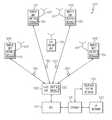
- FIG. 1is a block diagram of one embodiment of a distributed antenna system (DAS) 100 .
- DAS 100includes a host unit 102 and a plurality of remote units 106 .
- host units 102 and remote units 106are communicatively coupled via a communication link 130 to form a bidirectional communication network comprising a plurality of point-to-point communication links 130 .
- one or more of communication links 130are fiber optic cable as indicated in FIG. 1 .
- host units 102 and remote units 106may be interconnected via coaxial cable, or a combination of both coaxial cable and fiber optic cable.
- one or more of communication links 130are wireless millimeter wave links (e.g. E Band/70 GHz radio).
- a millimeter signal transceiveris coupled to host unit 102 and each remote unit 106 on each end of communication link 130 .
- one or more of communication links 130a microwave radio links where microwave radio transceivers are coupled to host unit 102 and remote units 106 .
- Remote units 106each house electronic devices and systems used for wirelessly transmitting and receiving modulated radio frequency (RF) communications via antenna 107 with one or more mobile subscriber units 108 .
- Host unit 102is coupled to at least one base transceiver station (BTS) 110 often referred to as a base station.
- BTS 110communicates voice and other data signals between the respective host unit 102 and a larger communication network via a gateway 124 coupled to a telephone system network 122 (for example, the public switched telephone network and/or wireless service provider networks) and an internet protocol (IP) network 120 , such as the Internet.
- IPinternet protocol
- DAS 100comprises part of a cellular telephone network and subscriber units 108 are cellular telephones.
- Downlink RF signalsare received from the BTS 110 at the host unit 102 , which the host unit 102 uses to generate one or more downlink transport signals for transmitting to one or more of the remote units 106 .
- Each such remote unit 106receives at least one downlink transport and reconstructs the downlink RF signals from the downlink transport signal and causes the reconstructed downlink RF signals to be radiated from a remote antenna 107 coupled to or included in that remote unit 106 .
- a similar processis performed in the uplink direction.
- Uplink RF signals received at one or more remote units 106 from subscriber 108are used to generate respective uplink transport signals that are transmitted from the respective remote units 106 to the host unit 102 .
- the host unit 102receives and combines the uplink transport signals transmitted from the multiple remote units 106 .
- the host unit 102communicates the combined uplink RF signals to the BTS 110 over a broadband signal.
- DAS 100comprises a digital DAS transport meaning that the downlink and uplink transport signals transmitted between host unit 102 and remote units 106 over communication links 130 are generated by digitizing the downlink and uplink RF signals, respectively.
- the downlink and uplink transport signalsare not analog RF signals but instead are digital data signals representing digital RF samples of a modulated RF signal.
- host unit 102will generate baseband digital samples of the modulated 900 MHz RF signal from BTS 110 , which are then distributed by host unit 102 to the remote units 106 .
- an all-digital BTSmay generate baseband digital samples directly.
- the digital samples of the modulated RF signalare converted from digital into an analog RF signal to be wirelessly radiated from the antennas 107 .
- the uplink analog RF signals received at remote unit 106are digitally sampled to generate digital RF data samples for the uplink transport signals.
- BTS 110 , host unit 102 and remote units 106each accommodate processing communication signals for multiple bands and multiple modulation schemes simultaneously.
- Each remote unit 106comprises a muting module 132 configured to mute a signal path in the respective remote unit 106 .
- Muting modules 132are configured to mute either uplink or downlink communications. When a muting module 132 mutes signals in the downlink direction, no signals are transmitted from the associated antenna 107 . Likewise when a muting module 132 mutes signals in the uplink direction, no signals are sent from the associated remote unit 106 to host unit 102 .
- Host unit 102also comprises at least one muting module 132 . More detail regarding muting modules 132 is provided below.
- FIG. 2is a block diagram of one embodiment of a remote unit 106 .
- Remote unit 106includes a serial radio frequency (SeRF) module 220 , a digital to analog radio frequency transceiver (DART) module 208 , a remote DART interface board (RDI) 224 , a power amplifier 210 , antenna 212 , a duplexer 211 , a low noise amplifier 214 .
- SeRF modules and DART modules described hereinare realized using FPGAs, ASICs, digital signal processing (DSP) boards, or similar devices.
- DART module 208provides bi-directional conversion between analog RF signals and digital sampled RF for the downlink and uplink transport signals transmitted between host unit 102 and remote units 106 .
- antenna 212receives a wireless RF signal from subscriber 208 and passes the RF signal to DART module 208 via low noise amplifier 214 .
- DART module 208receives the incoming analog RF signal and samples the analog RF signal to generate a digital data signal for use by SeRF module 220 .
- DART module 208receives digital sampled RF data from SeRF module 220 , up converts the sampled RF data to a broadcast frequency, and converts the digital RF samples to analog RF for wireless transmission.
- DART module 208After a signal is converted to an analog RF signal by DART module 208 , the analog RF signal is sent to power amplifier 210 for broadcast via antenna 212 .
- Power amplifier 210amplifies the RF signal received from DART module 208 for output through duplexer 211 to antenna 212 .
- Duplexer 211provides duplexing of the signal which is necessary to connect transmit and receive signals to a common antenna 212 .
- low noise amplifier 214is integrated into duplexer 211 .
- DART modulesmay function to optionally convert the digital RF samples into intermediate frequency (IF) samples instead of, or in addition to, baseband digital samples.
- DART module 208also comprises a muting module 132 for muting either or both of the uplink and downlink signal paths through DART module 208 .
- DART modules in a remote unitare specific for a particular frequency band.
- a single DART moduleoperates over a defined FDD band regardless of the modulation technology being used.
- frequency band adjustments in a remote unitcan be made by replacing a DART module covering one frequency band with a DART module covering a different frequency band.
- DART module 208is designed to transmit 850 MHz cellular transmissions.
- DART module 208transmits 1900 MHz PCS signals.
- Some of the other options for a DART module 208include Nextel 800 band, Nextel 900 band, PCS full band, PCS half band, BRS, WiMax, Long Term Evolution (LTE), and the European GSM 900,GSM 1800,and UMTS 2100.
- remote unit 106is configurable to any of the above frequency bands and technologies as well as any new technologies or frequency bands that are developed.
- SeRF module 220provides bi-directional conversion between a digital data stream and a high speed optical serial data stream.
- SeRF module 220receives incoming digital data streams from DART module 208 and sends a serial optical data stream over communication link 130 to host unit 102 .
- SeRF module 202receives an optical serial data stream from host unit 102 and provides a digital data stream to DART module 208 .
- SeRF module 220is coupled to RDI 224 .
- RDI 224has a plurality of connectors each of which is configured to receive a pluggable DART module 208 and couple DART module 208 to SeRF module 220 .
- RDI 224is a common interface that is configured to allow communication between SeRF module 220 and different varieties of DART modules 208 .
- RDI 204is a passive host backplane to which SeRF module 220 also connects.
- RDI 224is integrated with SeRF module 220 .
- FIG. 2illustrates a single DART module coupled to a SeRF module
- a single remote unit housingmay operate over multiple bands by possessing multiple DART modules.
- RDI 224provides separate connection interfaces allowing each DART module to communicate RF data samples with SeRF module 220 .
- SeRF module 220allows multiple DART modules to operate in parallel to communicate high speed optical serial data streams over a communication link with the host unit.
- a SeRF moduleactively multiplexes the signals from multiple DART modules (each DART module processing a different RF band) such that they are sent simultaneously over a single transport communication link.
- a SeRF modulepresents a clock signal to each DART module to which it is coupled to ensure synchronization.
- FIG. 2illustrates a single SeRF module connected to a single RDI
- a SeRF modulemay connect to multiple RDIs, each of which can connect to multiple DARTS.
- a SeRF modulecan connect to up to 4 RDIs, each of which can connect to up to 2 DARTs.
- SeRF module 220provides bi-directional conversion between a serial stream of RF, IF or baseband data samples (a SeRF stream) and a high speed optical serial data stream. In the uplink direction, SeRF module 220 receives an incoming SeRF stream from DART modules 208 and sends a serial optical data stream over communication links 130 to host unit 102 .
- SeRF module 220receives an optical serial data stream from host unit 102 and provides a SeRF stream to DART modules 208 .
- the present discussionapplies to such multiple band remote units, even though the present examples focus on the operation of a single DART module for simplicity.
- FIG. 3is a block diagram illustrating one embodiment of a host unit (shown generally at 102 ).
- Host unit 102is communicatively coupled to multiple remote units 106 via communication links 130 , as described with respect to FIG. 1 , to form a digital DAS.
- Host unit 102includes a host unit digital to analog radio frequency transceiver (DART) module 308 and a host unit serial radio frequency (SeRF) module 320 .
- SeRF module 320provides bi-directional conversion between a digital RF data samples and the multiple high speed optical serial data streams to and from the remote units 106 .
- DARTdigital to analog radio frequency transceiver
- SeRFserial radio frequency
- SeRF module 320receives incoming serial optical data streams from a plurality of remote units and converts each into a stream of digitized baseband RF data samples, which are summed into a broadband stream of RF data samples.
- DART module 308provides a bi-directional interface between SeRF module 320 and one or more base stations, such as BTS 110 . As with remote units 106 , when host unit 320 operates over multiple bands with multiple base stations, a separate DART module 308 is provided for each frequency band. Each DART module 308 also comprises a muting module 132 for muting either or both of the uplink and downlink signal paths through the DART module 308 .
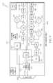
- FIG. 4is a block diagram of one embodiment of a DART module 400 for use in either host unit 102 (DART module 308 ) or remote units 106 (DART module 208 ).
- DART module 400has two main signal paths; a transmission path 404 and a reception path 406 .
- DART module 400forms parallel digital RF data from the incoming data stream, if needed, at FPGA 403 .
- FPGA 403is a logic device that is programmed to convert serial digital data into RF sampled data and programmed to convert RF sampled data into serial digital data.
- DART module 400then converts the digital RF data to an analog signal with digital to analog converter (DAC) 408 .
- DACdigital to analog converter
- Transmission path 404continues as DART module 400 filters, amplifies and up-converts the analog signal for RF transmission with an assortment of filters 410 , amplifiers 412 , an oscillator 414 , and an attenuator 416 .
- the transmission pathexits DART module 400 at a subminiature version A RF coaxial connector (SMA) connector 420 .
- SMAsubminiature version A RF coaxial connector
- the signalstravel in the opposite direction down reception path 406 , where they are converted from analog to digital and sent to a SeRF module.
- First signalsare received at SMA connector 420 .
- DART module 400then amplifies, down-converts, filters the incoming RF signal with a plurality of filters 410 , amplifiers 412 , oscillators 414 , and attenuators 416 .
- DART module 400then digitizes the signal with analog to digital converter 422 .
- FPGA 403then provides the data stream as parallel digital RF sampled data to a SeRF module. More detail regarding DAS 100 , host unit 102 , remote units 106 , or DART modules 400 is provided in co-pending U.S. application Ser. No. 11/627,251 which is hereby incorporated herein by reference.
- DART module 400also comprises a muting module 132 .
- a muting module 132During certain situations, one or both signal paths (i.e. receive path 406 and transmit path 404 ) of DART module 400 are muted by muting module 132 to prevent further transport of RF signals. For example, if there is an error in a hardware component on DART module 400 . One error which may occur is a synthesizer for the signal path becoming unsynchronized. An unsynchronized synthesizer can cause transmissions from the signal path to be placed on incorrect frequencies. Signals on incorrect frequencies can cause many problems, especially in a multi-carrier system where the incorrect frequency may overlap with a frequency already being transmitted on.
- the signal pathmay be muted because of a scheduled change in DAS 100 in which invalid data is sent through DAS 100 . Another reason is to prevent damage to power amplifiers 412 within DART module 400 caused by abnormalities in the signal. Other causes for muting the signal path include changes in a communication link 130 between host unit 102 and remote units 106 , re-configuration of time slots, excessive bit errors in the received data, management of an overflow situation, an unsynchronized synthesizer, or other situations. Finally, in one embodiment, all signals are muted which may cause DART module 400 to transmit above limits imposed by the FCC. Causes for muting a signal path are referred to herein as “events”.
- muting module 132may mute either receive path 406 , transmit path 404 or both.
- muting module 132mutes a signal path by setting the output power of one or more amplifiers in the signal path to zero. While the amplifier is muted, no (or very little) signal is sent from the signal path.
- muting module 132is a functional component of FPGA 403 .
- muting module 132is built in to the functionality of the FPGA 403 .
- FPGA 403also performs other functionalities.
- muting module 132is a stand alone component, including for example, an inline component in each signal path.
- DART module 403comprises two muting modules 132 , one in each signal path.
- muting module 132is functionality built into software operating on a processor on DART module 400 .
- Hard clampingOne method of muting a signal path with muting module 132 is referred to herein as “hard clamping” the signal path.
- Hard clamping the signalis typically used when an unplanned event occurs in either incoming data or in hardware of DART module 104 .
- Hard clampingshuts the signal path off quickly by setting the power of an amplifier directly from its current power level to zero (or near zero). For example, when muting module 132 recognizes that an event has occurred involving a hardware component on DART module 400 , muting module 132 quickly shuts down the power on the signal path comprising that hardware component.
- Muting module 132mutes the power by setting the power amplifiers 412 in the signal path from a normal (or current) operating state to zero power.
- FIG. 5Ashows one embodiment of an output signal during a hard clamp. As shown in FIG. 5A , the signal is moved quickly from 30 dB to ⁇ 100 dB.
- muting module 132recognizes an event and analyzes the event to determine whether to mute a signal line. For example, in some situations muting module 132 sends a report to software operating on host unit 102 and host unit 102 determines whether to mute the signal path. If host unit 102 determines that the signal path should be muted, host unit 102 sends a signal to muting module 132 to mute the signal path. To determine when an event has occurred, certain hardware components provide status bits identifying the status of the hardware component to muting module 132 . Muting module 132 monitors these status bits to determine when an event has occurred with the hardware components.
- one or more attenuatorsare used to reduce the power level of the signal.
- other methodsare used to reduce the power level of the signal.
- FIG. 5Billustrates one embodiment of a method 500 of hard clamping a signal path.
- muting module 132monitors the status bits from hardware components of DART module 400 ( 502 ). When a synthesizer (for example) is out of synchronization with DAS 100 , muting module 132 recognizes this in the status bit sent from the synthesizer ( 504 ). An out of synch synthesizer can cause signals transmitted from DART module 400 to be transmitted in incorrect frequencies. Once muting module 132 recognizes that an event has occurred, muting module 132 quickly sets amplifiers 412 in the synthesizer's signal path (e.g. transmit path 404 ) to zero power ( 506 ). Thus, unwanted effects caused by the synthesizer in the output signal are reduced.
- amplifiers 412 in the synthesizer's signal pathe.g. transmit path 404
- muting module 132monitors the event that caused the signal path to be muted ( 508 ). When the event is no longer present ( 510 ), muting module 132 ramps the power back up to the normal operating power ( 512 ). For example, an unsynchronized synthesizer event may be corrected through normal periodic re-synchronization of DART module 400 . In some embodiments, muting module 132 holds for a specified amount of time after an event is no longer present to monitor the event and ensure that the system is stable.
- muting module 132recognizes excessive bit errors in signals received, FPGA 403 assumes there is an error with upstream communication link 130 or host unit 102 , and mutes transmit path 404 to prevent incorrect data from being transmitted. Once muting module 132 has muted transmit path 404 , muting module 132 monitors the incoming bit stream to determine when the bit error rate is no longer excessive. Muting module 132 determines the incoming bit stream rate is no longer excessive when the bit error rate has dropped below a threshold. Once the bit error rate in the incoming bit stream has dropped below the threshold and, therefore, the event is no loner present, muting module 132 continues to monitor the incoming bit stream before ramping up the power of the power amplifier.
- Muting module 132monitors the incoming bit stream until the bit error rate remains below the threshold for a defined amount of time (e.g. 5 frames). Once the bit error rate is below the threshold for the defined amount of time, muting module 132 ramps the power up on the power amplifier to resume transmission of data.
- a defined amount of timee.g. 5 frames
- muting module 132incrementally steps up the power from zero until normal operating power is reached. Ramping up of the power may occur, for example, over half of a millisecond in time. For example, in one embodiment the power amplifier is stepped up in 5 dB increments from ⁇ 100 dB to 30 dB with 200 microsecond steps. Thus, at 200 microseconds in time, the power is stepped from 0 dB to 5 dB. At 400 microseconds the power is stepped from 5 dB to 10 dB and so on until the power is at 30 dB. In one embodiment, stepping up the power of power amplifier refers to the peak power of the amplifier.
- the amplifierwhen the amplifier is set to 10 dB, all incoming signals are clamped at 10 dB, such that any signal above 10 dB is only amplified to 10 dB by the power amplifier.
- other steps sizes, times, or methods of ramping up the power of power amplifierare used.
- the ramp upis similar (except in the opposite direction) to the ramp down described below and shown in FIGS. 6A and 6B .
- the ramp upis smooth.
- Another method of muting a signal pathis to ramp down the power over time. Ramping down of the power may occur, for example, over half of a millisecond in time. In one embodiment, the ramp down in smooth as shown in FIG. 6A . In another embodiment, the power amplifier is ramped down via 5 dB steps from 30 dB to 0 dB with each step lasting 200 microseconds as shown in FIG. 6B . Thus, at 200 microseconds in time, the power is stepped to from 30 dB to 25 dB. At 400 microseconds the power is stepped from 25 dB to 20 dB and so on until the power is at 30 dB. In one embodiment, stepping up the power of power amplifier refers to the peak power of the amplifier.
- the poweris ramped down when a scheduled event is occurring on DAS 100 .
- FIG. 6illustrates one embodiment of a method 600 for muting a signal line by ramping down power.
- Software operating on host unit 102orders DART modules 400 in remote units 106 to ramp down their power for the schedule event ( 602 ). For example, if an AWS band is to be added to DAS 100 which is currently operating in the PCS and the cellular bands, the time slots between host unit 102 and remote units 106 will have to be shuffled.
- Host unit 102orders DART modules 400 on remote units 106 to ramp down their power. Each of the DART modules 400 then ramps their power down to zero as described above ( 604 ).
- DART modules 400Once each of the DART modules 400 has ramped their power down to zero, the time slots are shuffled. Once it is determined how many time slots are on each fiber and the time slots have been re-stabilized, host unit 102 orders DART modules 400 on remote units 106 to resume operation ( 606 ). Similar to that described for the hard clamp, when DART modules 400 resume operation, DART modules 400 a ramp up the power over time ( 608 ).
- the time between initiating a mute and the return to normal operating poweris reduced to make the mutes unperceivable to a human ear.
- FIG. 7is a block diagram of one embodiment of a SeRF module 702 and a DART module 704 having muting capabilities.
- SeRF module 702comprises software operating on a processing device 706 (e.g., a PowerPC). Processing device 706 is communicatively coupled to a SeRF FPGA 708 .
- DART module 704comprises a DART FPGA 710 communicatively coupled to SeRF FGPA 708 .
- DART module 704comprises a receive path shown generally at 712 and a transmit path shown generally at 714 .
- Receive path 712comprises RF circuitry which takes signals from a linear amplifier (LNA) 716 .
- LNAlinear amplifier
- Attenuators 718are digital step attenuators (DSAs).
- DSAsdigital step attenuators
- ADCanalog to digital converter
- the digitized signalsare then sent to DART FPGA 710 .
- transmit path 714digitized signals from DART FPGA 710 are converted to analog by digital to analog converter (DAC) 722 .
- DACdigital to analog converter
- the analog signalsthen pass through three attenuators 724 before being sent to power amplifier 726 for transmission. Similar to receive path 712 , some components of the RF circuitry in transmit path 714 are not shown to simplify explanation of the muting functionality.
- DART FPGA 710is configured to comprise interface logic 728 which enables sending and receiving signals from SeRF FPGA 708 .
- DART FGPA 710is also configured to comprise a register 730 where encoded data is stored and another register 732 where decoded data is stored for encoding and decoding signals to/from attenuators 718 , 724 .
- Digital muting logic 734provides digital muting for receive path 712 .
- digital muting logic 736provides digital muting for transmit path 714 .
- DART FGPA 710is configured to comprise general control logic 738 for receiving status signals from RF circuitry, and transmitting control signals to attenuators 718 , 724 and digital muting logic 734 , 736 .
- SeRF module 702 and DART module 704perform two types of muting; digital muting and analog muting.
- Digital muteperformed by digital muting control 734 , 736 of DART FPGA 710 .
- Digital mutingmay be either a hard clamped or ramped mute.
- a digital muteis a multiplication of a digitized RF signal by a factor of less than one. For example, in one embodiment a hard clamp digital mute is effectuated by multiplying a digitized RF signal by 0.
- a digital ramped muteis a stepped multiplication of a digitized RF signal by, for example, 0.8,then 0.6,then 0.4,then 0.2,and finally by 0.
- Digital muting logic 734 and 736implement the multiplication of the digitized RF signal by the factor.
- signals coming out of the respective digital muting logic 734 , 736have a digital power level of 0.
- Analog mutingis ramped mute of attenuators 718 , 724 by similarly stepping up the attenuation of attenuators 718 , 724 .
- Digital muting by hard clampingis initiated when an RF circuitry component is not correctly configured or otherwise malfunctioning.
- the RF circuitry componentsprovide status bits to general control logic 738 .
- the status bitsprovide information relating to the state of the RF circuitry components which are used by DART FPGA 710 and the software operating on processing device 706 to determine when to mute a signal line.
- hard clamp muteis initiated when RF circuitry components are in a state that requires muting. This is because improper states for RF circuitry may have extreme detrimental effects on the signals output including transmitting in incorrect frequency bands, or damage to amplifiers or other components.
- general control logic 738recognizes a status bit as indicating a state the requires muting, general control logic 738 immediately initiates a hard clamp mute to quickly shut down the signal line.
- general control logic 738sends a signal to the digital muting logic 734 , 736 that mutes the signal path in which the RF circuitry situation occurred. For example, if a synthesizer in transmit path 714 is unlocked, general control logic 738 recognizes that the status bit from synthesizer indicates that the synthesizer is unlocked, and general control logic 738 sends a signal to digital muting logic 736 to hard clamp signals on transmit path 714 .
- FIG. 8Aillustrates one embodiment of a signal 802 output from a signal path when a hard clamp is initiated. As shown, hard clamping the signal shuts down the signal waveform. When a hard clamp is removed the waveform resumes.
- a ramped muteis typically initiated and controlled by the software operating on processing device 706 .
- the softwaresends a message to SeRF FPGA 708 which sends the message to DART FPGA 710 .
- the messageis encoded by register encoder 734 and sent to, for example, transmit path control logic 736 .
- Transmit path control logic 736then initiates the mute prescribed in the message.
- the softwarecontrols the ramped mute. In other words, the message sent by the software instructs the muting control logic 734 , 736 to multiply by a certain factor.
- the softwaresends an instruction to multiply the digitized RF signal by a factor of 0.8. Then after a delay time, the software sends another message instructing the muting control logic 734 to multiply the digitized RF signal by a factor of 0.6. This continues until the muting control logic 734 , 736 is multiplying by a factor of 0. Similar instructions are provided to effectuate a ramped up un-mute.
- the steps of the ramped down muteare controlled by DART FGPA 710 .
- the softwaresends a message to DART FPGA 710 to initiate a ramped mute.
- DART FPGA 710then controls the power level and time duration of each step of the ramped mute. Accordingly, the software does not directly control the power level of each step.
- FIG. 8Billustrates one embodiment of a signal 804 output from a signal path when a ramped mute is initiated.
- a ramped down signalgradually diminishes in power when the ramped mute is initiated.
- a ramped power increasebegins.
- the power levelgradually increases until full power is reached.
- FIG. 8Cillustrates a signal 806 showing the power level instructions for digital muting and ramping up of a signal.
- state graph 808illustrates the state of DART FPGA 710 .
- State graph 810illustrates the status of the muting control logic 734 , 736 .
- DART FPGA 710has muting control logic 734 , 736 set to mute on ( 817 ).
- signal 802is fully muted at ⁇ (max)dB.
- DART FGPA 710enters a good state 818 , and muting control logic 734 , 736 is turned off ( 819 ).
- signal 802is ramped up to full power, 0 dB of muting.
- muting control logic 734 , 736is turned on ( 821 ) as a hard clamp.
- signal 806is reduced quickly to ⁇ (max) dB.
- the softwarecontrols analog muting of attenuators 718 , 724 .
- Attenuators 718 , 724are controlled to perform a stepped ramped mute.
- the softwareprovides a message to DART FPGA 710 which is sent by general control logic 738 to attenuators 718 , 724 .
- the messageinstructs one or more of attenuators 718 , 724 to increase the attenuation of the signal.
- the attenuation of attenuators 718 , 724is increased. This continues until the signal is all (or mostly) attenuated.
- the softwaresends a message to increase attenuation on attenuators 724 .
- the softwarealso controls the ramp up of the signal by ramping down the attenuation of attenuators 718 , 724 .
- the ramping up and down of attenuatorsoccurs over a much longer time frame than the digital ramping.
- the digital rampingoccurs over roughly 500 milliseconds, while the analog ramping with attenuators occurs over 5-10 seconds.
- digital and analog mutingare performed concurrently.
- FIG. 9illustrates a flow diagram of one embodiment of operation of a remote unit 106 performing digital and analog muting of a signal.
- power of the systemis turned on.
- softwareinitiates a digital mute since none of the system has been set up.
- system componentsare initialized such as selection of transmission band and configuration of FPGAs.
- DART FPGA 710recognizes that the synthesizer is unlocked (since the synthesizer has yet to be locked during initialization) based on status bits received from the synthesizer.
- DART FPGA 710sets a hard clamp digital mute ( 912 ) to ensure no improper signals are transmitted while the synthesizer is unlocked.
- the softwaresends the synthesizer parameters to DART FPGA 710 to program synthesizer.
- DART FPGA 710determines whether the synthesizer has been locked. If the synthesizer has been locked, DART FPGA 710 releases the digital mute ( 918 ).
- DART FPGA 710reports to the software that the synthesizer has been locked.
- the softwaredetermines if any other mute condition exist.
- DART FPGA 710holds muting control logic 734 , 736 on mute ( 924 ). DART FPGA 710 then reports to the software that the synthesizer is still unlocked 726 . At this point, software sets an analog mute on the signal path ( 928 ). Software also initiates a digital ramped mute ( 930 ). As can be seen from the flow chart, software may initiate a digital mute, however, the signal may already be muted by a previous hard clamped mute.
- muting control logic 734 , 736does not perform an additional mute, but will remain muted until both the ramped mute and the hard clamp mute are removed.
- flowreturns to re-configure FPGAs if necessary.
- a software mute conditionexists 930 .
- softwareinitiates an analog mute ( 928 ), and a digital mute ( 930 ).
- FIG. 10is another flow chart illustrating a method of one embodiment of the present invention for a method for muting a signal in a radio frequency (RF) processing board.
- the methodbegins at 1010 with transporting digital data signals through a data path on the RF processing board.
- the methodproceeds to 1020 with monitoring events affecting the data path.
- an unplanned eventis identified (determined at 1030 )
- the methodproceeds to 1040 with applying a hard clamping to mute the signal power of the data path.
- a planned eventis identified (determined at 1030 )
- the methodproceeds to 1050 with applying a ramp to mute the signal power of the data path.
- the methodproceeds to 1060 with applying a ramp to restore the signal power of the data path when the event has ended.
Landscapes
- Engineering & Computer Science (AREA)
- Computer Networks & Wireless Communication (AREA)
- Signal Processing (AREA)
- Amplifiers (AREA)
Abstract
Description
Claims (27)
Priority Applications (1)
| Application Number | Priority Date | Filing Date | Title |
|---|---|---|---|
| US12/643,116US8306563B2 (en) | 2009-01-29 | 2009-12-21 | Method and apparatus for muting a digital link in a distributed antenna system |
Applications Claiming Priority (2)
| Application Number | Priority Date | Filing Date | Title |
|---|---|---|---|
| US14825609P | 2009-01-29 | 2009-01-29 | |
| US12/643,116US8306563B2 (en) | 2009-01-29 | 2009-12-21 | Method and apparatus for muting a digital link in a distributed antenna system |
Publications (2)
| Publication Number | Publication Date |
|---|---|
| US20100190519A1 US20100190519A1 (en) | 2010-07-29 |
| US8306563B2true US8306563B2 (en) | 2012-11-06 |
Family
ID=42354573
Family Applications (1)
| Application Number | Title | Priority Date | Filing Date |
|---|---|---|---|
| US12/643,116Expired - Fee RelatedUS8306563B2 (en) | 2009-01-29 | 2009-12-21 | Method and apparatus for muting a digital link in a distributed antenna system |
Country Status (1)
| Country | Link |
|---|---|
| US (1) | US8306563B2 (en) |
Cited By (58)
| Publication number | Priority date | Publication date | Assignee | Title |
|---|---|---|---|---|
| US20130095873A1 (en)* | 2011-10-14 | 2013-04-18 | Qualcomm Incorporated | Distributed antenna systems and methods of wireless communications for facilitating simulcasting and de-simulcasting of downlink transmissions |
| US20140308043A1 (en)* | 2010-10-13 | 2014-10-16 | Ccs Technology, Inc. | Local power management for remote antenna units in distributed antenna systems |
| US20140308044A1 (en)* | 2010-10-13 | 2014-10-16 | Ccs Technology, Inc. | Power management for remote antenna units in distributed antenna systems |
| US8908607B2 (en) | 2012-10-31 | 2014-12-09 | Andrew Llc | Digital baseband transport in telecommunications distribution systems |
| US9037143B2 (en) | 2010-08-16 | 2015-05-19 | Corning Optical Communications LLC | Remote antenna clusters and related systems, components, and methods supporting digital data signal propagation between remote antenna units |
| US9042732B2 (en) | 2010-05-02 | 2015-05-26 | Corning Optical Communications LLC | Providing digital data services in optical fiber-based distributed radio frequency (RF) communication systems, and related components and methods |
| US9112611B2 (en) | 2009-02-03 | 2015-08-18 | Corning Optical Communications LLC | Optical fiber-based distributed antenna systems, components, and related methods for calibration thereof |
| US9178635B2 (en) | 2014-01-03 | 2015-11-03 | Corning Optical Communications Wireless Ltd | Separation of communication signal sub-bands in distributed antenna systems (DASs) to reduce interference |
| US9179321B2 (en) | 2012-08-09 | 2015-11-03 | Axell Wireless Ltd. | Digital capacity centric distributed antenna system |
| US9184843B2 (en) | 2011-04-29 | 2015-11-10 | Corning Optical Communications LLC | Determining propagation delay of communications in distributed antenna systems, and related components, systems, and methods |
| US9219879B2 (en) | 2009-11-13 | 2015-12-22 | Corning Optical Communications LLC | Radio-over-fiber (ROF) system for protocol-independent wired and/or wireless communication |
| US9240835B2 (en) | 2011-04-29 | 2016-01-19 | Corning Optical Communications LLC | Systems, methods, and devices for increasing radio frequency (RF) power in distributed antenna systems |
| US9247543B2 (en) | 2013-07-23 | 2016-01-26 | Corning Optical Communications Wireless Ltd | Monitoring non-supported wireless spectrum within coverage areas of distributed antenna systems (DASs) |
| US9253003B1 (en) | 2014-09-25 | 2016-02-02 | Corning Optical Communications Wireless Ltd | Frequency shifting a communications signal(S) in a multi-frequency distributed antenna system (DAS) to avoid or reduce frequency interference |
| US9312941B2 (en) | 2011-10-14 | 2016-04-12 | Qualcomm Incorporated | Base stations and methods for facilitating dynamic simulcasting and de-simulcasting in a distributed antenna system |
| US9319138B2 (en) | 2010-02-15 | 2016-04-19 | Corning Optical Communications LLC | Dynamic cell bonding (DCB) for radio-over-fiber (RoF)-based networks and communication systems and related methods |
| US9325429B2 (en) | 2011-02-21 | 2016-04-26 | Corning Optical Communications LLC | Providing digital data services as electrical signals and radio-frequency (RF) communications over optical fiber in distributed communications systems, and related components and methods |
| US9338823B2 (en) | 2012-03-23 | 2016-05-10 | Corning Optical Communications Wireless Ltd | Radio-frequency integrated circuit (RFIC) chip(s) for providing distributed antenna system functionalities, and related components, systems, and methods |
| US9357551B2 (en) | 2014-05-30 | 2016-05-31 | Corning Optical Communications Wireless Ltd | Systems and methods for simultaneous sampling of serial digital data streams from multiple analog-to-digital converters (ADCS), including in distributed antenna systems |
| US9385810B2 (en) | 2013-09-30 | 2016-07-05 | Corning Optical Communications Wireless Ltd | Connection mapping in distributed communication systems |
| US9420542B2 (en) | 2014-09-25 | 2016-08-16 | Corning Optical Communications Wireless Ltd | System-wide uplink band gain control in a distributed antenna system (DAS), based on per band gain control of remote uplink paths in remote units |
| US9455784B2 (en) | 2012-10-31 | 2016-09-27 | Corning Optical Communications Wireless Ltd | Deployable wireless infrastructures and methods of deploying wireless infrastructures |
| US9497706B2 (en) | 2013-02-20 | 2016-11-15 | Corning Optical Communications Wireless Ltd | Power management in distributed antenna systems (DASs), and related components, systems, and methods |
| US9509133B2 (en) | 2014-06-27 | 2016-11-29 | Corning Optical Communications Wireless Ltd | Protection of distributed antenna systems |
| US9525488B2 (en) | 2010-05-02 | 2016-12-20 | Corning Optical Communications LLC | Digital data services and/or power distribution in optical fiber-based distributed communications systems providing digital data and radio frequency (RF) communications services, and related components and methods |
| US9602210B2 (en) | 2014-09-24 | 2017-03-21 | Corning Optical Communications Wireless Ltd | Flexible head-end chassis supporting automatic identification and interconnection of radio interface modules and optical interface modules in an optical fiber-based distributed antenna system (DAS) |
| US9621293B2 (en) | 2012-08-07 | 2017-04-11 | Corning Optical Communications Wireless Ltd | Distribution of time-division multiplexed (TDM) management services in a distributed antenna system, and related components, systems, and methods |
| US9647758B2 (en) | 2012-11-30 | 2017-05-09 | Corning Optical Communications Wireless Ltd | Cabling connectivity monitoring and verification |
| US9653861B2 (en) | 2014-09-17 | 2017-05-16 | Corning Optical Communications Wireless Ltd | Interconnection of hardware components |
| US9661781B2 (en) | 2013-07-31 | 2017-05-23 | Corning Optical Communications Wireless Ltd | Remote units for distributed communication systems and related installation methods and apparatuses |
| US9673904B2 (en) | 2009-02-03 | 2017-06-06 | Corning Optical Communications LLC | Optical fiber-based distributed antenna systems, components, and related methods for calibration thereof |
| US9681313B2 (en) | 2015-04-15 | 2017-06-13 | Corning Optical Communications Wireless Ltd | Optimizing remote antenna unit performance using an alternative data channel |
| US9685782B2 (en) | 2010-11-24 | 2017-06-20 | Corning Optical Communications LLC | Power distribution module(s) capable of hot connection and/or disconnection for distributed antenna systems, and related power units, components, and methods |
| US9715157B2 (en) | 2013-06-12 | 2017-07-25 | Corning Optical Communications Wireless Ltd | Voltage controlled optical directional coupler |
| US9729251B2 (en) | 2012-07-31 | 2017-08-08 | Corning Optical Communications LLC | Cooling system control in distributed antenna systems |
| US9730228B2 (en) | 2014-08-29 | 2017-08-08 | Corning Optical Communications Wireless Ltd | Individualized gain control of remote uplink band paths in a remote unit in a distributed antenna system (DAS), based on combined uplink power level in the remote unit |
| US9775123B2 (en) | 2014-03-28 | 2017-09-26 | Corning Optical Communications Wireless Ltd. | Individualized gain control of uplink paths in remote units in a distributed antenna system (DAS) based on individual remote unit contribution to combined uplink power |
| US9785175B2 (en) | 2015-03-27 | 2017-10-10 | Corning Optical Communications Wireless, Ltd. | Combining power from electrically isolated power paths for powering remote units in a distributed antenna system(s) (DASs) |
| US9807700B2 (en) | 2015-02-19 | 2017-10-31 | Corning Optical Communications Wireless Ltd | Offsetting unwanted downlink interference signals in an uplink path in a distributed antenna system (DAS) |
| US9813229B2 (en) | 2007-10-22 | 2017-11-07 | Corning Optical Communications Wireless Ltd | Communication system using low bandwidth wires |
| US9826410B2 (en) | 2009-04-29 | 2017-11-21 | Commscope Technologies Llc | Distributed antenna system for wireless network systems |
| US9948349B2 (en) | 2015-07-17 | 2018-04-17 | Corning Optical Communications Wireless Ltd | IOT automation and data collection system |
| US9974074B2 (en) | 2013-06-12 | 2018-05-15 | Corning Optical Communications Wireless Ltd | Time-division duplexing (TDD) in distributed communications systems, including distributed antenna systems (DASs) |
| US10096909B2 (en) | 2014-11-03 | 2018-10-09 | Corning Optical Communications Wireless Ltd. | Multi-band monopole planar antennas configured to facilitate improved radio frequency (RF) isolation in multiple-input multiple-output (MIMO) antenna arrangement |
| US10110308B2 (en) | 2014-12-18 | 2018-10-23 | Corning Optical Communications Wireless Ltd | Digital interface modules (DIMs) for flexibly distributing digital and/or analog communications signals in wide-area analog distributed antenna systems (DASs) |
| US10128951B2 (en) | 2009-02-03 | 2018-11-13 | Corning Optical Communications LLC | Optical fiber-based distributed antenna systems, components, and related methods for monitoring and configuring thereof |
| US10136200B2 (en) | 2012-04-25 | 2018-11-20 | Corning Optical Communications LLC | Distributed antenna system architectures |
| US10135533B2 (en) | 2014-11-13 | 2018-11-20 | Corning Optical Communications Wireless Ltd | Analog distributed antenna systems (DASS) supporting distribution of digital communications signals interfaced from a digital signal source and analog radio frequency (RF) communications signals |
| US10187151B2 (en) | 2014-12-18 | 2019-01-22 | Corning Optical Communications Wireless Ltd | Digital-analog interface modules (DAIMs) for flexibly distributing digital and/or analog communications signals in wide-area analog distributed antenna systems (DASs) |
| US10236924B2 (en) | 2016-03-31 | 2019-03-19 | Corning Optical Communications Wireless Ltd | Reducing out-of-channel noise in a wireless distribution system (WDS) |
| US10257056B2 (en) | 2012-11-28 | 2019-04-09 | Corning Optical Communications LLC | Power management for distributed communication systems, and related components, systems, and methods |
| US10396917B2 (en) | 2014-09-23 | 2019-08-27 | Axell Wireless Ltd. | Automatic mapping and handling PIM and other uplink interferences in digital distributed antenna systems |
| US10455497B2 (en) | 2013-11-26 | 2019-10-22 | Corning Optical Communications LLC | Selective activation of communications services on power-up of a remote unit(s) in a wireless communication system (WCS) based on power consumption |
| US10560214B2 (en) | 2015-09-28 | 2020-02-11 | Corning Optical Communications LLC | Downlink and uplink communication path switching in a time-division duplex (TDD) distributed antenna system (DAS) |
| US10659163B2 (en) | 2014-09-25 | 2020-05-19 | Corning Optical Communications LLC | Supporting analog remote antenna units (RAUs) in digital distributed antenna systems (DASs) using analog RAU digital adaptors |
| US10992484B2 (en) | 2013-08-28 | 2021-04-27 | Corning Optical Communications LLC | Power management for distributed communication systems, and related components, systems, and methods |
| US11064501B2 (en) | 2014-12-23 | 2021-07-13 | Axell Wireless Ltd. | Harmonizing noise aggregation and noise management in distributed antenna system |
| US11296504B2 (en) | 2010-11-24 | 2022-04-05 | Corning Optical Communications LLC | Power distribution module(s) capable of hot connection and/or disconnection for wireless communication systems, and related power units, components, and methods |
Families Citing this family (8)
| Publication number | Priority date | Publication date | Assignee | Title |
|---|---|---|---|---|
| US9020555B2 (en)* | 2010-04-05 | 2015-04-28 | Intel Corporation | System and method for performance enhancement in heterogeneous wireless access network employing distributed antenna system |
| WO2012041393A1 (en)* | 2010-10-01 | 2012-04-05 | Nokia Siemens Networks Oy | Muting data transmissions |
| CN102468876B (en)* | 2010-11-01 | 2015-03-18 | 鼎桥通信技术有限公司 | Distributed antenna system and power distribution method thereof |
| US9363768B2 (en)* | 2012-07-09 | 2016-06-07 | Dali Systems Co. Ltd. | Self-optimizing distributed antenna system using soft frequency reuse |
| WO2015126444A1 (en)* | 2014-02-21 | 2015-08-27 | Commscope Technologies Llc | Distributed antenna system transport link quality measurement |
| US10425081B2 (en)* | 2015-01-28 | 2019-09-24 | Hitachi, Ltd. | Field programmable logic array |
| CN107005860B (en)* | 2015-05-08 | 2020-07-07 | 京信通信系统(中国)有限公司 | Signal backup system and method for active DAS system near-end unit |
| US10382847B2 (en)* | 2017-04-24 | 2019-08-13 | Andrew Wireless Systems Gmbh | Systems and methods for communicating signaling over an optical distributed antenna system |
Citations (27)
| Publication number | Priority date | Publication date | Assignee | Title |
|---|---|---|---|---|
| US4183054A (en) | 1977-09-30 | 1980-01-08 | Harris Corporation | Digital, frequency-translated, plural-channel, vestigial sideband television communication system |
| US4611323A (en) | 1983-05-24 | 1986-09-09 | Ant Nachrichtentechnik Gmbh | Method for transmitting digitally coded analog signals |
| US4628501A (en) | 1983-12-29 | 1986-12-09 | The United States Of America As Represented By The Secretary Of The Army | Optical communications systems |
| US4654843A (en) | 1982-09-17 | 1987-03-31 | U.S. Philips Corporation | Signal distribution system |
| US4691292A (en) | 1983-04-13 | 1987-09-01 | Rca Corporation | System for digital multiband filtering |
| EP0391597A2 (en) | 1989-04-04 | 1990-10-10 | AT&T Corp. | Optical fiber microcellular mobile radio |
| US4999831A (en) | 1989-10-19 | 1991-03-12 | United Telecommunications, Inc. | Synchronous quantized subcarrier multiplexer for digital transport of video, voice and data |
| WO1991015927A1 (en) | 1990-04-10 | 1991-10-17 | British Telecommunications Public Limited Company | Signal distribution |
| US5193109A (en) | 1989-02-06 | 1993-03-09 | Pactel Corporation | Zoned microcell with sector scanning for cellular telephone system |
| US5229850A (en)* | 1990-07-30 | 1993-07-20 | Kabushiki Kaisha Toshiba | Video monitoring system including a memory for storing and transmitting a video signal immediately following the occurrence of an event |
| US5243598A (en) | 1991-04-02 | 1993-09-07 | Pactel Corporation | Microcell system in digital cellular |
| US5321849A (en) | 1991-05-22 | 1994-06-14 | Southwestern Bell Technology Resources, Inc. | System for controlling signal level at both ends of a transmission link based on a detected valve |
| US5339184A (en) | 1992-06-15 | 1994-08-16 | Gte Laboratories Incorporated | Fiber optic antenna remoting for multi-sector cell sites |
| US6016352A (en)* | 1997-11-20 | 2000-01-18 | Intel Corporation | Low distortion audio muting circuit |
| US20050085743A1 (en)* | 2003-01-22 | 2005-04-21 | Hacker David C. | Apparatus and method for intraoperative neural monitoring |
| US20050083115A1 (en)* | 2003-10-15 | 2005-04-21 | Texas Instruments Incorporated | Soft transitions between muted and unmuted states in class D audio amplifiers |
| US20050215284A1 (en)* | 2004-03-26 | 2005-09-29 | Broadcom Corporation | Collaborative coexistence with dynamic prioritization of wireless devices |
| US7043208B2 (en)* | 2002-10-15 | 2006-05-09 | Motorola, Inc. | Method and apparatus to reduce interference in a communication device |
| US7177606B2 (en)* | 2002-07-10 | 2007-02-13 | General Instrument Corporation | Control system for controlling an output signal power level of a wireless transmitter |
| US20070116300A1 (en)* | 2004-12-22 | 2007-05-24 | Broadcom Corporation | Channel decoding for wireless telephones with multiple microphones and multiple description transmission |
| US20080211565A1 (en)* | 2005-09-29 | 2008-09-04 | Matsushita Electric Industrial Co., Ltd. | Mute Circuit |
| US20090067263A1 (en)* | 2007-09-12 | 2009-03-12 | Hynix Semiconductor Inc. | Core voltage discharge driver |
| US20090116578A1 (en)* | 2007-11-07 | 2009-05-07 | Roland Sperlich | Distortion compensation in a communication system |
| US20090160547A1 (en)* | 2007-12-20 | 2009-06-25 | Asit Shankar | Method and system for transitioning between operation states in an output system |
| US20100019820A1 (en)* | 2007-01-23 | 2010-01-28 | Pai Venkatesh P | Digital control system and method |
| US20100158278A1 (en)* | 2008-12-19 | 2010-06-24 | Christian Larsen | Power Management Controller for Drivers |
| US8160272B1 (en)* | 2008-07-15 | 2012-04-17 | Integrated Device Technology, Inc. | Audio output circuits having ramped attenuation circuits that inhibit pop disturbances when audio sources are switched |
Family Cites Families (1)
| Publication number | Priority date | Publication date | Assignee | Title |
|---|---|---|---|---|
| GB2197531B (en)* | 1986-11-08 | 1991-02-06 | Stc Plc | Distributed feedback laser |
- 2009
- 2009-12-21USUS12/643,116patent/US8306563B2/ennot_activeExpired - Fee Related
Patent Citations (27)
| Publication number | Priority date | Publication date | Assignee | Title |
|---|---|---|---|---|
| US4183054A (en) | 1977-09-30 | 1980-01-08 | Harris Corporation | Digital, frequency-translated, plural-channel, vestigial sideband television communication system |
| US4654843A (en) | 1982-09-17 | 1987-03-31 | U.S. Philips Corporation | Signal distribution system |
| US4691292A (en) | 1983-04-13 | 1987-09-01 | Rca Corporation | System for digital multiband filtering |
| US4611323A (en) | 1983-05-24 | 1986-09-09 | Ant Nachrichtentechnik Gmbh | Method for transmitting digitally coded analog signals |
| US4628501A (en) | 1983-12-29 | 1986-12-09 | The United States Of America As Represented By The Secretary Of The Army | Optical communications systems |
| US5193109A (en) | 1989-02-06 | 1993-03-09 | Pactel Corporation | Zoned microcell with sector scanning for cellular telephone system |
| EP0391597A2 (en) | 1989-04-04 | 1990-10-10 | AT&T Corp. | Optical fiber microcellular mobile radio |
| US4999831A (en) | 1989-10-19 | 1991-03-12 | United Telecommunications, Inc. | Synchronous quantized subcarrier multiplexer for digital transport of video, voice and data |
| WO1991015927A1 (en) | 1990-04-10 | 1991-10-17 | British Telecommunications Public Limited Company | Signal distribution |
| US5229850A (en)* | 1990-07-30 | 1993-07-20 | Kabushiki Kaisha Toshiba | Video monitoring system including a memory for storing and transmitting a video signal immediately following the occurrence of an event |
| US5243598A (en) | 1991-04-02 | 1993-09-07 | Pactel Corporation | Microcell system in digital cellular |
| US5321849A (en) | 1991-05-22 | 1994-06-14 | Southwestern Bell Technology Resources, Inc. | System for controlling signal level at both ends of a transmission link based on a detected valve |
| US5339184A (en) | 1992-06-15 | 1994-08-16 | Gte Laboratories Incorporated | Fiber optic antenna remoting for multi-sector cell sites |
| US6016352A (en)* | 1997-11-20 | 2000-01-18 | Intel Corporation | Low distortion audio muting circuit |
| US7177606B2 (en)* | 2002-07-10 | 2007-02-13 | General Instrument Corporation | Control system for controlling an output signal power level of a wireless transmitter |
| US7043208B2 (en)* | 2002-10-15 | 2006-05-09 | Motorola, Inc. | Method and apparatus to reduce interference in a communication device |
| US20050085743A1 (en)* | 2003-01-22 | 2005-04-21 | Hacker David C. | Apparatus and method for intraoperative neural monitoring |
| US20050083115A1 (en)* | 2003-10-15 | 2005-04-21 | Texas Instruments Incorporated | Soft transitions between muted and unmuted states in class D audio amplifiers |
| US20050215284A1 (en)* | 2004-03-26 | 2005-09-29 | Broadcom Corporation | Collaborative coexistence with dynamic prioritization of wireless devices |
| US20070116300A1 (en)* | 2004-12-22 | 2007-05-24 | Broadcom Corporation | Channel decoding for wireless telephones with multiple microphones and multiple description transmission |
| US20080211565A1 (en)* | 2005-09-29 | 2008-09-04 | Matsushita Electric Industrial Co., Ltd. | Mute Circuit |
| US20100019820A1 (en)* | 2007-01-23 | 2010-01-28 | Pai Venkatesh P | Digital control system and method |
| US20090067263A1 (en)* | 2007-09-12 | 2009-03-12 | Hynix Semiconductor Inc. | Core voltage discharge driver |
| US20090116578A1 (en)* | 2007-11-07 | 2009-05-07 | Roland Sperlich | Distortion compensation in a communication system |
| US20090160547A1 (en)* | 2007-12-20 | 2009-06-25 | Asit Shankar | Method and system for transitioning between operation states in an output system |
| US8160272B1 (en)* | 2008-07-15 | 2012-04-17 | Integrated Device Technology, Inc. | Audio output circuits having ramped attenuation circuits that inhibit pop disturbances when audio sources are switched |
| US20100158278A1 (en)* | 2008-12-19 | 2010-06-24 | Christian Larsen | Power Management Controller for Drivers |
Non-Patent Citations (2)
| Title |
|---|
| Grace, Martin K., "Synchronous Quantized Subcarrier Multiplexing for Transport of Video, Voice and Data", "IEEE Journal on Selected Areas in Communications", Sep. 1990, pp. 1351-1358, vol. 8, No. 7, Publisher: IEEE. |
| Harvey et al., "Cordless Communications Utilising Radio Over Fibre Techniques for the Local Loop", "IEEE International Conference on Communications", Jun. 1991, pp. 1171-1175, Publisher: IEEE. |
Cited By (121)
| Publication number | Priority date | Publication date | Assignee | Title |
|---|---|---|---|---|
| US9813229B2 (en) | 2007-10-22 | 2017-11-07 | Corning Optical Communications Wireless Ltd | Communication system using low bandwidth wires |
| US10128951B2 (en) | 2009-02-03 | 2018-11-13 | Corning Optical Communications LLC | Optical fiber-based distributed antenna systems, components, and related methods for monitoring and configuring thereof |
| US9900097B2 (en) | 2009-02-03 | 2018-02-20 | Corning Optical Communications LLC | Optical fiber-based distributed antenna systems, components, and related methods for calibration thereof |
| US10153841B2 (en) | 2009-02-03 | 2018-12-11 | Corning Optical Communications LLC | Optical fiber-based distributed antenna systems, components, and related methods for calibration thereof |
| US9673904B2 (en) | 2009-02-03 | 2017-06-06 | Corning Optical Communications LLC | Optical fiber-based distributed antenna systems, components, and related methods for calibration thereof |
| US9112611B2 (en) | 2009-02-03 | 2015-08-18 | Corning Optical Communications LLC | Optical fiber-based distributed antenna systems, components, and related methods for calibration thereof |
| US10499253B2 (en) | 2009-04-29 | 2019-12-03 | Commscope Technologies Llc | Distributed antenna system for wireless network systems |
| US9826410B2 (en) | 2009-04-29 | 2017-11-21 | Commscope Technologies Llc | Distributed antenna system for wireless network systems |
| US9219879B2 (en) | 2009-11-13 | 2015-12-22 | Corning Optical Communications LLC | Radio-over-fiber (ROF) system for protocol-independent wired and/or wireless communication |
| US9729238B2 (en) | 2009-11-13 | 2017-08-08 | Corning Optical Communications LLC | Radio-over-fiber (ROF) system for protocol-independent wired and/or wireless communication |
| US9485022B2 (en) | 2009-11-13 | 2016-11-01 | Corning Optical Communications LLC | Radio-over-fiber (ROF) system for protocol-independent wired and/or wireless communication |
| US9319138B2 (en) | 2010-02-15 | 2016-04-19 | Corning Optical Communications LLC | Dynamic cell bonding (DCB) for radio-over-fiber (RoF)-based networks and communication systems and related methods |
| US9042732B2 (en) | 2010-05-02 | 2015-05-26 | Corning Optical Communications LLC | Providing digital data services in optical fiber-based distributed radio frequency (RF) communication systems, and related components and methods |
| US9525488B2 (en) | 2010-05-02 | 2016-12-20 | Corning Optical Communications LLC | Digital data services and/or power distribution in optical fiber-based distributed communications systems providing digital data and radio frequency (RF) communications services, and related components and methods |
| US9853732B2 (en) | 2010-05-02 | 2017-12-26 | Corning Optical Communications LLC | Digital data services and/or power distribution in optical fiber-based distributed communications systems providing digital data and radio frequency (RF) communications services, and related components and methods |
| US9270374B2 (en) | 2010-05-02 | 2016-02-23 | Corning Optical Communications LLC | Providing digital data services in optical fiber-based distributed radio frequency (RF) communications systems, and related components and methods |
| US10014944B2 (en) | 2010-08-16 | 2018-07-03 | Corning Optical Communications LLC | Remote antenna clusters and related systems, components, and methods supporting digital data signal propagation between remote antenna units |
| US9037143B2 (en) | 2010-08-16 | 2015-05-19 | Corning Optical Communications LLC | Remote antenna clusters and related systems, components, and methods supporting digital data signal propagation between remote antenna units |
| US10849064B2 (en) | 2010-10-13 | 2020-11-24 | Corning Optical Communications LLC | Power management for remote antenna units in distributed antenna systems |
| US9160449B2 (en)* | 2010-10-13 | 2015-10-13 | Ccs Technology, Inc. | Local power management for remote antenna units in distributed antenna systems |
| US20140308043A1 (en)* | 2010-10-13 | 2014-10-16 | Ccs Technology, Inc. | Local power management for remote antenna units in distributed antenna systems |
| US20140308044A1 (en)* | 2010-10-13 | 2014-10-16 | Ccs Technology, Inc. | Power management for remote antenna units in distributed antenna systems |
| US9699723B2 (en) | 2010-10-13 | 2017-07-04 | Ccs Technology, Inc. | Local power management for remote antenna units in distributed antenna systems |
| US11671914B2 (en) | 2010-10-13 | 2023-06-06 | Corning Optical Communications LLC | Power management for remote antenna units in distributed antenna systems |
| US11212745B2 (en) | 2010-10-13 | 2021-12-28 | Corning Optical Communications LLC | Power management for remote antenna units in distributed antenna systems |
| US10104610B2 (en) | 2010-10-13 | 2018-10-16 | Corning Optical Communications LLC | Local power management for remote antenna units in distributed antenna systems |
| US11178609B2 (en) | 2010-10-13 | 2021-11-16 | Corning Optical Communications LLC | Power management for remote antenna units in distributed antenna systems |
| US9419712B2 (en) | 2010-10-13 | 2016-08-16 | Ccs Technology, Inc. | Power management for remote antenna units in distributed antenna systems |
| US10420025B2 (en) | 2010-10-13 | 2019-09-17 | Corning Optical Communications LLC | Local power management for remote antenna units in distributed antenna systems |
| US10425891B2 (en) | 2010-10-13 | 2019-09-24 | Corning Optical Communications LLC | Power management for remote antenna units in distributed antenna systems |
| US10045288B2 (en) | 2010-10-13 | 2018-08-07 | Corning Optical Communications LLC | Power management for remote antenna units in distributed antenna systems |
| US9252874B2 (en)* | 2010-10-13 | 2016-02-02 | Ccs Technology, Inc | Power management for remote antenna units in distributed antenna systems |
| US10750442B2 (en) | 2010-10-13 | 2020-08-18 | Corning Optical Communications LLC | Local power management for remote antenna units in distributed antenna systems |
| US11224014B2 (en) | 2010-10-13 | 2022-01-11 | Corning Optical Communications LLC | Power management for remote antenna units in distributed antenna systems |
| US10454270B2 (en) | 2010-11-24 | 2019-10-22 | Corning Optical Communicatons LLC | Power distribution module(s) capable of hot connection and/or disconnection for wireless communication systems, and related power units, components, and methods |
| US11296504B2 (en) | 2010-11-24 | 2022-04-05 | Corning Optical Communications LLC | Power distribution module(s) capable of hot connection and/or disconnection for wireless communication systems, and related power units, components, and methods |
| US9685782B2 (en) | 2010-11-24 | 2017-06-20 | Corning Optical Communications LLC | Power distribution module(s) capable of hot connection and/or disconnection for distributed antenna systems, and related power units, components, and methods |
| US11114852B2 (en) | 2010-11-24 | 2021-09-07 | Corning Optical Communications LLC | Power distribution module(s) capable of hot connection and/or disconnection for wireless communication systems, and related power units, components, and methods |
| US11715949B2 (en) | 2010-11-24 | 2023-08-01 | Corning Optical Communications LLC | Power distribution module(s) capable of hot connection and/or disconnection for wireless communication systems, and related power units, components, and methods |
| US9813164B2 (en) | 2011-02-21 | 2017-11-07 | Corning Optical Communications LLC | Providing digital data services as electrical signals and radio-frequency (RF) communications over optical fiber in distributed communications systems, and related components and methods |
| US10205538B2 (en) | 2011-02-21 | 2019-02-12 | Corning Optical Communications LLC | Providing digital data services as electrical signals and radio-frequency (RF) communications over optical fiber in distributed communications systems, and related components and methods |
| US9325429B2 (en) | 2011-02-21 | 2016-04-26 | Corning Optical Communications LLC | Providing digital data services as electrical signals and radio-frequency (RF) communications over optical fiber in distributed communications systems, and related components and methods |
| US9240835B2 (en) | 2011-04-29 | 2016-01-19 | Corning Optical Communications LLC | Systems, methods, and devices for increasing radio frequency (RF) power in distributed antenna systems |
| US9184843B2 (en) | 2011-04-29 | 2015-11-10 | Corning Optical Communications LLC | Determining propagation delay of communications in distributed antenna systems, and related components, systems, and methods |
| US9369222B2 (en) | 2011-04-29 | 2016-06-14 | Corning Optical Communications LLC | Determining propagation delay of communications in distributed antenna systems, and related components, systems, and methods |
| US9807722B2 (en) | 2011-04-29 | 2017-10-31 | Corning Optical Communications LLC | Determining propagation delay of communications in distributed antenna systems, and related components, systems, and methods |
| US10148347B2 (en) | 2011-04-29 | 2018-12-04 | Corning Optical Communications LLC | Systems, methods, and devices for increasing radio frequency (RF) power in distributed antenna systems |
| US9806797B2 (en) | 2011-04-29 | 2017-10-31 | Corning Optical Communications LLC | Systems, methods, and devices for increasing radio frequency (RF) power in distributed antenna systems |
| US9312941B2 (en) | 2011-10-14 | 2016-04-12 | Qualcomm Incorporated | Base stations and methods for facilitating dynamic simulcasting and de-simulcasting in a distributed antenna system |
| US9276685B2 (en)* | 2011-10-14 | 2016-03-01 | Qualcomm Incorporated | Distributed antenna systems and methods of wireless communications for facilitating simulcasting and de-simulcasting of downlink transmissions |
| US20150057039A1 (en)* | 2011-10-14 | 2015-02-26 | Qualcomm Incorporated | Distributed antenna systems and methods of wireless communications for facilitating simulcasting and de-simulcasting of downlink transmissions |
| US9276686B2 (en)* | 2011-10-14 | 2016-03-01 | Qualcomm Incorporated | Distributed antenna systems and methods of wireless communications for facilitating simulcasting and de-simulcasting of downlink transmissions |
| US20130095873A1 (en)* | 2011-10-14 | 2013-04-18 | Qualcomm Incorporated | Distributed antenna systems and methods of wireless communications for facilitating simulcasting and de-simulcasting of downlink transmissions |
| US9338823B2 (en) | 2012-03-23 | 2016-05-10 | Corning Optical Communications Wireless Ltd | Radio-frequency integrated circuit (RFIC) chip(s) for providing distributed antenna system functionalities, and related components, systems, and methods |
| US9948329B2 (en) | 2012-03-23 | 2018-04-17 | Corning Optical Communications Wireless, LTD | Radio-frequency integrated circuit (RFIC) chip(s) for providing distributed antenna system functionalities, and related components, systems, and methods |
| US10141959B2 (en) | 2012-03-23 | 2018-11-27 | Corning Optical Communications Wireless Ltd | Radio-frequency integrated circuit (RFIC) chip(s) for providing distributed antenna system functionalities, and related components, systems, and methods |
| US10349156B2 (en) | 2012-04-25 | 2019-07-09 | Corning Optical Communications LLC | Distributed antenna system architectures |
| US10136200B2 (en) | 2012-04-25 | 2018-11-20 | Corning Optical Communications LLC | Distributed antenna system architectures |
| US9729251B2 (en) | 2012-07-31 | 2017-08-08 | Corning Optical Communications LLC | Cooling system control in distributed antenna systems |
| US9621293B2 (en) | 2012-08-07 | 2017-04-11 | Corning Optical Communications Wireless Ltd | Distribution of time-division multiplexed (TDM) management services in a distributed antenna system, and related components, systems, and methods |
| US9973968B2 (en) | 2012-08-07 | 2018-05-15 | Corning Optical Communications Wireless Ltd | Distribution of time-division multiplexed (TDM) management services in a distributed antenna system, and related components, systems, and methods |
| US9179321B2 (en) | 2012-08-09 | 2015-11-03 | Axell Wireless Ltd. | Digital capacity centric distributed antenna system |
| US9794791B2 (en) | 2012-08-09 | 2017-10-17 | Axell Wireless Ltd. | Digital capacity centric distributed antenna system |
| US9455784B2 (en) | 2012-10-31 | 2016-09-27 | Corning Optical Communications Wireless Ltd | Deployable wireless infrastructures and methods of deploying wireless infrastructures |
| US11419119B2 (en) | 2012-10-31 | 2022-08-16 | Commscope Technologies Llc | Digital baseband transport in telecommunications distribution systems |
| US10841923B2 (en) | 2012-10-31 | 2020-11-17 | Commscope Technologies Llc | Digital baseband transport in telecommunications distribution systems |
| US9967885B2 (en) | 2012-10-31 | 2018-05-08 | Commscope Technologies Llc | Digital baseband transport in telecommunications distribution systems |
| US9462603B2 (en) | 2012-10-31 | 2016-10-04 | Commscope Technologies Llc | Digital baseband transport in telecommunications distribution systems |
| US8908607B2 (en) | 2012-10-31 | 2014-12-09 | Andrew Llc | Digital baseband transport in telecommunications distribution systems |
| US10257056B2 (en) | 2012-11-28 | 2019-04-09 | Corning Optical Communications LLC | Power management for distributed communication systems, and related components, systems, and methods |
| US10999166B2 (en) | 2012-11-28 | 2021-05-04 | Corning Optical Communications LLC | Power management for distributed communication systems, and related components, systems, and methods |
| US11665069B2 (en) | 2012-11-28 | 2023-05-30 | Corning Optical Communications LLC | Power management for distributed communication systems, and related components, systems, and methods |
| US10530670B2 (en) | 2012-11-28 | 2020-01-07 | Corning Optical Communications LLC | Power management for distributed communication systems, and related components, systems, and methods |
| US9647758B2 (en) | 2012-11-30 | 2017-05-09 | Corning Optical Communications Wireless Ltd | Cabling connectivity monitoring and verification |
| US10361782B2 (en) | 2012-11-30 | 2019-07-23 | Corning Optical Communications LLC | Cabling connectivity monitoring and verification |
| US9497706B2 (en) | 2013-02-20 | 2016-11-15 | Corning Optical Communications Wireless Ltd | Power management in distributed antenna systems (DASs), and related components, systems, and methods |
| US9974074B2 (en) | 2013-06-12 | 2018-05-15 | Corning Optical Communications Wireless Ltd | Time-division duplexing (TDD) in distributed communications systems, including distributed antenna systems (DASs) |
| US9715157B2 (en) | 2013-06-12 | 2017-07-25 | Corning Optical Communications Wireless Ltd | Voltage controlled optical directional coupler |
| US11291001B2 (en) | 2013-06-12 | 2022-03-29 | Corning Optical Communications LLC | Time-division duplexing (TDD) in distributed communications systems, including distributed antenna systems (DASs) |
| US11792776B2 (en) | 2013-06-12 | 2023-10-17 | Corning Optical Communications LLC | Time-division duplexing (TDD) in distributed communications systems, including distributed antenna systems (DASs) |
| US9247543B2 (en) | 2013-07-23 | 2016-01-26 | Corning Optical Communications Wireless Ltd | Monitoring non-supported wireless spectrum within coverage areas of distributed antenna systems (DASs) |
| US9967754B2 (en) | 2013-07-23 | 2018-05-08 | Corning Optical Communications Wireless Ltd | Monitoring non-supported wireless spectrum within coverage areas of distributed antenna systems (DASs) |
| US10292056B2 (en) | 2013-07-23 | 2019-05-14 | Corning Optical Communications LLC | Monitoring non-supported wireless spectrum within coverage areas of distributed antenna systems (DASs) |
| US9526020B2 (en) | 2013-07-23 | 2016-12-20 | Corning Optical Communications Wireless Ltd | Monitoring non-supported wireless spectrum within coverage areas of distributed antenna systems (DASs) |
| US9661781B2 (en) | 2013-07-31 | 2017-05-23 | Corning Optical Communications Wireless Ltd | Remote units for distributed communication systems and related installation methods and apparatuses |
| US10992484B2 (en) | 2013-08-28 | 2021-04-27 | Corning Optical Communications LLC | Power management for distributed communication systems, and related components, systems, and methods |
| US11516030B2 (en) | 2013-08-28 | 2022-11-29 | Corning Optical Communications LLC | Power management for distributed communication systems, and related components, systems, and methods |
| US9385810B2 (en) | 2013-09-30 | 2016-07-05 | Corning Optical Communications Wireless Ltd | Connection mapping in distributed communication systems |
| US10455497B2 (en) | 2013-11-26 | 2019-10-22 | Corning Optical Communications LLC | Selective activation of communications services on power-up of a remote unit(s) in a wireless communication system (WCS) based on power consumption |
| US9178635B2 (en) | 2014-01-03 | 2015-11-03 | Corning Optical Communications Wireless Ltd | Separation of communication signal sub-bands in distributed antenna systems (DASs) to reduce interference |
| US9775123B2 (en) | 2014-03-28 | 2017-09-26 | Corning Optical Communications Wireless Ltd. | Individualized gain control of uplink paths in remote units in a distributed antenna system (DAS) based on individual remote unit contribution to combined uplink power |
| US9807772B2 (en) | 2014-05-30 | 2017-10-31 | Corning Optical Communications Wireless Ltd. | Systems and methods for simultaneous sampling of serial digital data streams from multiple analog-to-digital converters (ADCs), including in distributed antenna systems |
| US9357551B2 (en) | 2014-05-30 | 2016-05-31 | Corning Optical Communications Wireless Ltd | Systems and methods for simultaneous sampling of serial digital data streams from multiple analog-to-digital converters (ADCS), including in distributed antenna systems |
| US9509133B2 (en) | 2014-06-27 | 2016-11-29 | Corning Optical Communications Wireless Ltd | Protection of distributed antenna systems |
| US9730228B2 (en) | 2014-08-29 | 2017-08-08 | Corning Optical Communications Wireless Ltd | Individualized gain control of remote uplink band paths in a remote unit in a distributed antenna system (DAS), based on combined uplink power level in the remote unit |
| US10397929B2 (en) | 2014-08-29 | 2019-08-27 | Corning Optical Communications LLC | Individualized gain control of remote uplink band paths in a remote unit in a distributed antenna system (DAS), based on combined uplink power level in the remote unit |
| US9653861B2 (en) | 2014-09-17 | 2017-05-16 | Corning Optical Communications Wireless Ltd | Interconnection of hardware components |
| US10396917B2 (en) | 2014-09-23 | 2019-08-27 | Axell Wireless Ltd. | Automatic mapping and handling PIM and other uplink interferences in digital distributed antenna systems |
| US9602210B2 (en) | 2014-09-24 | 2017-03-21 | Corning Optical Communications Wireless Ltd | Flexible head-end chassis supporting automatic identification and interconnection of radio interface modules and optical interface modules in an optical fiber-based distributed antenna system (DAS) |
| US9929810B2 (en) | 2014-09-24 | 2018-03-27 | Corning Optical Communications Wireless Ltd | Flexible head-end chassis supporting automatic identification and interconnection of radio interface modules and optical interface modules in an optical fiber-based distributed antenna system (DAS) |
| US9515855B2 (en) | 2014-09-25 | 2016-12-06 | Corning Optical Communications Wireless Ltd | Frequency shifting a communications signal(s) in a multi-frequency distributed antenna system (DAS) to avoid or reduce frequency interference |
| US9788279B2 (en) | 2014-09-25 | 2017-10-10 | Corning Optical Communications Wireless Ltd | System-wide uplink band gain control in a distributed antenna system (DAS), based on per-band gain control of remote uplink paths in remote units |
| US9420542B2 (en) | 2014-09-25 | 2016-08-16 | Corning Optical Communications Wireless Ltd | System-wide uplink band gain control in a distributed antenna system (DAS), based on per band gain control of remote uplink paths in remote units |
| US10659163B2 (en) | 2014-09-25 | 2020-05-19 | Corning Optical Communications LLC | Supporting analog remote antenna units (RAUs) in digital distributed antenna systems (DASs) using analog RAU digital adaptors |
| US9253003B1 (en) | 2014-09-25 | 2016-02-02 | Corning Optical Communications Wireless Ltd | Frequency shifting a communications signal(S) in a multi-frequency distributed antenna system (DAS) to avoid or reduce frequency interference |
| US10096909B2 (en) | 2014-11-03 | 2018-10-09 | Corning Optical Communications Wireless Ltd. | Multi-band monopole planar antennas configured to facilitate improved radio frequency (RF) isolation in multiple-input multiple-output (MIMO) antenna arrangement |
| US10135533B2 (en) | 2014-11-13 | 2018-11-20 | Corning Optical Communications Wireless Ltd | Analog distributed antenna systems (DASS) supporting distribution of digital communications signals interfaced from a digital signal source and analog radio frequency (RF) communications signals |
| US10523326B2 (en) | 2014-11-13 | 2019-12-31 | Corning Optical Communications LLC | Analog distributed antenna systems (DASS) supporting distribution of digital communications signals interfaced from a digital signal source and analog radio frequency (RF) communications signals |
| US10187151B2 (en) | 2014-12-18 | 2019-01-22 | Corning Optical Communications Wireless Ltd | Digital-analog interface modules (DAIMs) for flexibly distributing digital and/or analog communications signals in wide-area analog distributed antenna systems (DASs) |
| US10361783B2 (en) | 2014-12-18 | 2019-07-23 | Corning Optical Communications LLC | Digital interface modules (DIMs) for flexibly distributing digital and/or analog communications signals in wide-area analog distributed antenna systems (DASs) |
| US10110308B2 (en) | 2014-12-18 | 2018-10-23 | Corning Optical Communications Wireless Ltd | Digital interface modules (DIMs) for flexibly distributing digital and/or analog communications signals in wide-area analog distributed antenna systems (DASs) |
| US10523327B2 (en) | 2014-12-18 | 2019-12-31 | Corning Optical Communications LLC | Digital-analog interface modules (DAIMs) for flexibly distributing digital and/or analog communications signals in wide-area analog distributed antenna systems (DASs) |
| US11064501B2 (en) | 2014-12-23 | 2021-07-13 | Axell Wireless Ltd. | Harmonizing noise aggregation and noise management in distributed antenna system |
| US10292114B2 (en) | 2015-02-19 | 2019-05-14 | Corning Optical Communications LLC | Offsetting unwanted downlink interference signals in an uplink path in a distributed antenna system (DAS) |
| US9807700B2 (en) | 2015-02-19 | 2017-10-31 | Corning Optical Communications Wireless Ltd | Offsetting unwanted downlink interference signals in an uplink path in a distributed antenna system (DAS) |
| US9785175B2 (en) | 2015-03-27 | 2017-10-10 | Corning Optical Communications Wireless, Ltd. | Combining power from electrically isolated power paths for powering remote units in a distributed antenna system(s) (DASs) |
| US9681313B2 (en) | 2015-04-15 | 2017-06-13 | Corning Optical Communications Wireless Ltd | Optimizing remote antenna unit performance using an alternative data channel |
| US10009094B2 (en) | 2015-04-15 | 2018-06-26 | Corning Optical Communications Wireless Ltd | Optimizing remote antenna unit performance using an alternative data channel |
| US9948349B2 (en) | 2015-07-17 | 2018-04-17 | Corning Optical Communications Wireless Ltd | IOT automation and data collection system |
| US10560214B2 (en) | 2015-09-28 | 2020-02-11 | Corning Optical Communications LLC | Downlink and uplink communication path switching in a time-division duplex (TDD) distributed antenna system (DAS) |
| US10236924B2 (en) | 2016-03-31 | 2019-03-19 | Corning Optical Communications Wireless Ltd | Reducing out-of-channel noise in a wireless distribution system (WDS) |
Also Published As
| Publication number | Publication date |
|---|---|
| US20100190519A1 (en) | 2010-07-29 |
Similar Documents
| Publication | Publication Date | Title |
|---|---|---|
| US8306563B2 (en) | Method and apparatus for muting a digital link in a distributed antenna system | |
| US8437383B2 (en) | Method and apparatus for digitally equalizing a signal in a distributed antenna system | |
| KR100352852B1 (en) | A transmitting device of receiving signal for optical bts | |
| US8694034B2 (en) | System and method for the distribution of radio-frequency signals | |
| KR102128800B1 (en) | Distributed antenna system | |
| AU2014226135B2 (en) | A distributed antenna system having high near-far performance | |
| EP3661321A1 (en) | Distributed antenna system architectures | |
| US9247511B2 (en) | Synchronization in a flexible bandwidth wireless network | |
| WO2000072476A2 (en) | Embedded forward reference and control | |
| EP3432486A1 (en) | Base station signal matching device, and base station interface unit and distributed antenna system comprising same | |
| KR20160126610A (en) | Distributed antenna system and remote apparatus thereof | |
| US11297689B2 (en) | Systems and methods for uplink noise suppression for a distributed antenna system | |
| EP3242421A1 (en) | Node unit capable of measuring delay and distributed antenna system comprising same | |
| KR102308249B1 (en) | Multi Channel-Distributed Antenna System comprising 5G converter Unit | |
| US20040125869A1 (en) | Method and apparatus for non-intrusive transceiver property adjustment | |
| US6839544B1 (en) | System and method for remote monitoring of a transmitter in a wireless base station | |
| JP4503565B2 (en) | Transmission transmitting apparatus, transmission receiving apparatus, transmission signal transmitting method, and transmission signal receiving method | |
| KR102417238B1 (en) | Distributed antenna system and signal processing method thereof | |
| KR100668106B1 (en) | Time delay correction device of base station system | |
| KR101835439B1 (en) | Adapting apparatus for inter operation between rrh and repeater on wcdma network | |
| KR102250111B1 (en) | Headend for distributed antenna system and operating method thereof | |
| EP4277158A1 (en) | A mobile telecommunication signal booster | |
| KR20180072408A (en) | Headend for distributed antenna system and operating method thereof | |
| KR20170073407A (en) | Apparatus for integrating monitor port of digital repeater | |
| WO2005083961A1 (en) | Method and apparatus for non-intrusive transceiver property adjustment |
Legal Events
| Date | Code | Title | Description |
|---|---|---|---|
| AS | Assignment | Owner name:ADC TELECOMMUNICATIONS, INC., MINNESOTA Free format text:ASSIGNMENT OF ASSIGNORS INTEREST;ASSIGNORS:ZAVADSKY, DEAN;CANNON, JEFFREY J.;HEDIN, JOHN M.;REEL/FRAME:023682/0200 Effective date:20091215 | |
| ZAAA | Notice of allowance and fees due | Free format text:ORIGINAL CODE: NOA | |
| ZAAB | Notice of allowance mailed | Free format text:ORIGINAL CODE: MN/=. | |
| STCF | Information on status: patent grant | Free format text:PATENTED CASE | |
| AS | Assignment | Owner name:TYCO ELECTRONICS SERVICES GMBH, SWITZERLAND Free format text:ASSIGNMENT OF ASSIGNORS INTEREST;ASSIGNOR:ADC TELECOMMUNICATIONS, INC.;REEL/FRAME:036060/0174 Effective date:20110930 | |
| AS | Assignment | Owner name:COMMSCOPE EMEA LIMITED, IRELAND Free format text:ASSIGNMENT OF ASSIGNORS INTEREST;ASSIGNOR:TYCO ELECTRONICS SERVICES GMBH;REEL/FRAME:036956/0001 Effective date:20150828 | |
| AS | Assignment | Owner name:COMMSCOPE TECHNOLOGIES LLC, NORTH CAROLINA Free format text:ASSIGNMENT OF ASSIGNORS INTEREST;ASSIGNOR:COMMSCOPE EMEA LIMITED;REEL/FRAME:037012/0001 Effective date:20150828 | |
| AS | Assignment | Owner name:JPMORGAN CHASE BANK, N.A., AS COLLATERAL AGENT, ILLINOIS Free format text:PATENT SECURITY AGREEMENT (TERM);ASSIGNOR:COMMSCOPE TECHNOLOGIES LLC;REEL/FRAME:037513/0709 Effective date:20151220 Owner name:JPMORGAN CHASE BANK, N.A., AS COLLATERAL AGENT, ILLINOIS Free format text:PATENT SECURITY AGREEMENT (ABL);ASSIGNOR:COMMSCOPE TECHNOLOGIES LLC;REEL/FRAME:037514/0196 Effective date:20151220 Owner name:JPMORGAN CHASE BANK, N.A., AS COLLATERAL AGENT, IL Free format text:PATENT SECURITY AGREEMENT (ABL);ASSIGNOR:COMMSCOPE TECHNOLOGIES LLC;REEL/FRAME:037514/0196 Effective date:20151220 Owner name:JPMORGAN CHASE BANK, N.A., AS COLLATERAL AGENT, IL Free format text:PATENT SECURITY AGREEMENT (TERM);ASSIGNOR:COMMSCOPE TECHNOLOGIES LLC;REEL/FRAME:037513/0709 Effective date:20151220 | |
| FPAY | Fee payment | Year of fee payment:4 | |
| AS | Assignment | Owner name:ANDREW LLC, NORTH CAROLINA Free format text:RELEASE BY SECURED PARTY;ASSIGNOR:JPMORGAN CHASE BANK, N.A.;REEL/FRAME:048840/0001 Effective date:20190404 Owner name:COMMSCOPE, INC. OF NORTH CAROLINA, NORTH CAROLINA Free format text:RELEASE BY SECURED PARTY;ASSIGNOR:JPMORGAN CHASE BANK, N.A.;REEL/FRAME:048840/0001 Effective date:20190404 Owner name:COMMSCOPE TECHNOLOGIES LLC, NORTH CAROLINA Free format text:RELEASE BY SECURED PARTY;ASSIGNOR:JPMORGAN CHASE BANK, N.A.;REEL/FRAME:048840/0001 Effective date:20190404 Owner name:REDWOOD SYSTEMS, INC., NORTH CAROLINA Free format text:RELEASE BY SECURED PARTY;ASSIGNOR:JPMORGAN CHASE BANK, N.A.;REEL/FRAME:048840/0001 Effective date:20190404 Owner name:ALLEN TELECOM LLC, ILLINOIS Free format text:RELEASE BY SECURED PARTY;ASSIGNOR:JPMORGAN CHASE BANK, N.A.;REEL/FRAME:048840/0001 Effective date:20190404 Owner name:COMMSCOPE, INC. OF NORTH CAROLINA, NORTH CAROLINA Free format text:RELEASE BY SECURED PARTY;ASSIGNOR:JPMORGAN CHASE BANK, N.A.;REEL/FRAME:049260/0001 Effective date:20190404 Owner name:REDWOOD SYSTEMS, INC., NORTH CAROLINA Free format text:RELEASE BY SECURED PARTY;ASSIGNOR:JPMORGAN CHASE BANK, N.A.;REEL/FRAME:049260/0001 Effective date:20190404 Owner name:ALLEN TELECOM LLC, ILLINOIS Free format text:RELEASE BY SECURED PARTY;ASSIGNOR:JPMORGAN CHASE BANK, N.A.;REEL/FRAME:049260/0001 Effective date:20190404 Owner name:ANDREW LLC, NORTH CAROLINA Free format text:RELEASE BY SECURED PARTY;ASSIGNOR:JPMORGAN CHASE BANK, N.A.;REEL/FRAME:049260/0001 Effective date:20190404 Owner name:COMMSCOPE TECHNOLOGIES LLC, NORTH CAROLINA Free format text:RELEASE BY SECURED PARTY;ASSIGNOR:JPMORGAN CHASE BANK, N.A.;REEL/FRAME:049260/0001 Effective date:20190404 | |
| AS | Assignment | Owner name:JPMORGAN CHASE BANK, N.A., NEW YORK Free format text:TERM LOAN SECURITY AGREEMENT;ASSIGNORS:COMMSCOPE, INC. OF NORTH CAROLINA;COMMSCOPE TECHNOLOGIES LLC;ARRIS ENTERPRISES LLC;AND OTHERS;REEL/FRAME:049905/0504 Effective date:20190404 Owner name:JPMORGAN CHASE BANK, N.A., NEW YORK Free format text:ABL SECURITY AGREEMENT;ASSIGNORS:COMMSCOPE, INC. OF NORTH CAROLINA;COMMSCOPE TECHNOLOGIES LLC;ARRIS ENTERPRISES LLC;AND OTHERS;REEL/FRAME:049892/0396 Effective date:20190404 Owner name:WILMINGTON TRUST, NATIONAL ASSOCIATION, AS COLLATE Free format text:PATENT SECURITY AGREEMENT;ASSIGNOR:COMMSCOPE TECHNOLOGIES LLC;REEL/FRAME:049892/0051 Effective date:20190404 Owner name:WILMINGTON TRUST, NATIONAL ASSOCIATION, AS COLLATERAL AGENT, CONNECTICUT Free format text:PATENT SECURITY AGREEMENT;ASSIGNOR:COMMSCOPE TECHNOLOGIES LLC;REEL/FRAME:049892/0051 Effective date:20190404 | |
| MAFP | Maintenance fee payment | Free format text:PAYMENT OF MAINTENANCE FEE, 8TH YEAR, LARGE ENTITY (ORIGINAL EVENT CODE: M1552); ENTITY STATUS OF PATENT OWNER: LARGE ENTITY Year of fee payment:8 | |
| AS | Assignment | Owner name:WILMINGTON TRUST, DELAWARE Free format text:SECURITY INTEREST;ASSIGNORS:ARRIS SOLUTIONS, INC.;ARRIS ENTERPRISES LLC;COMMSCOPE TECHNOLOGIES LLC;AND OTHERS;REEL/FRAME:060752/0001 Effective date:20211115 | |
| FEPP | Fee payment procedure | Free format text:MAINTENANCE FEE REMINDER MAILED (ORIGINAL EVENT CODE: REM.); ENTITY STATUS OF PATENT OWNER: LARGE ENTITY | |
| AS | Assignment | Owner name:OUTDOOR WIRELESS NETWORKS LLC, NORTH CAROLINA Free format text:ASSIGNMENT OF ASSIGNORS INTEREST;ASSIGNOR:COMMSCOPE TECHNOLOGIES LLC;REEL/FRAME:068107/0089 Effective date:20240701 | |
| AS | Assignment | Owner name:JPMORGAN CHASE BANK, N.A., AS COLLATERAL AGENT, NEW YORK Free format text:PATENT SECURITY AGREEMENT (TERM);ASSIGNOR:OUTDOOR WIRELESS NETWORKS LLC;REEL/FRAME:068770/0632 Effective date:20240813 Owner name:JPMORGAN CHASE BANK, N.A., AS COLLATERAL AGENT, NEW YORK Free format text:PATENT SECURITY AGREEMENT (ABL);ASSIGNOR:OUTDOOR WIRELESS NETWORKS LLC;REEL/FRAME:068770/0460 Effective date:20240813 | |
| LAPS | Lapse for failure to pay maintenance fees | Free format text:PATENT EXPIRED FOR FAILURE TO PAY MAINTENANCE FEES (ORIGINAL EVENT CODE: EXP.); ENTITY STATUS OF PATENT OWNER: LARGE ENTITY | |
| STCH | Information on status: patent discontinuation | Free format text:PATENT EXPIRED DUE TO NONPAYMENT OF MAINTENANCE FEES UNDER 37 CFR 1.362 | |
| AS | Assignment | Owner name:OUTDOOR WIRELESS NETWORKS LLC, NORTH CAROLINA Free format text:RELEASE OF SECURITY INTEREST AT REEL/FRAME 068770/0632;ASSIGNOR:JPMORGAN CHASE BANK, N.A., AS COLLATERAL AGENT;REEL/FRAME:069743/0264 Effective date:20241217 Owner name:RUCKUS WIRELESS, LLC (F/K/A RUCKUS WIRELESS, INC.), NORTH CAROLINA Free format text:RELEASE OF SECURITY INTEREST AT REEL/FRAME 049905/0504;ASSIGNOR:JPMORGAN CHASE BANK, N.A., AS COLLATERAL AGENT;REEL/FRAME:071477/0255 Effective date:20241217 Owner name:COMMSCOPE TECHNOLOGIES LLC, NORTH CAROLINA Free format text:RELEASE OF SECURITY INTEREST AT REEL/FRAME 049905/0504;ASSIGNOR:JPMORGAN CHASE BANK, N.A., AS COLLATERAL AGENT;REEL/FRAME:071477/0255 Effective date:20241217 Owner name:COMMSCOPE, INC. OF NORTH CAROLINA, NORTH CAROLINA Free format text:RELEASE OF SECURITY INTEREST AT REEL/FRAME 049905/0504;ASSIGNOR:JPMORGAN CHASE BANK, N.A., AS COLLATERAL AGENT;REEL/FRAME:071477/0255 Effective date:20241217 Owner name:ARRIS SOLUTIONS, INC., NORTH CAROLINA Free format text:RELEASE OF SECURITY INTEREST AT REEL/FRAME 049905/0504;ASSIGNOR:JPMORGAN CHASE BANK, N.A., AS COLLATERAL AGENT;REEL/FRAME:071477/0255 Effective date:20241217 Owner name:ARRIS TECHNOLOGY, INC., NORTH CAROLINA Free format text:RELEASE OF SECURITY INTEREST AT REEL/FRAME 049905/0504;ASSIGNOR:JPMORGAN CHASE BANK, N.A., AS COLLATERAL AGENT;REEL/FRAME:071477/0255 Effective date:20241217 Owner name:ARRIS ENTERPRISES LLC (F/K/A ARRIS ENTERPRISES, INC.), NORTH CAROLINA Free format text:RELEASE OF SECURITY INTEREST AT REEL/FRAME 049905/0504;ASSIGNOR:JPMORGAN CHASE BANK, N.A., AS COLLATERAL AGENT;REEL/FRAME:071477/0255 Effective date:20241217 | |
| FP | Lapsed due to failure to pay maintenance fee | Effective date:20241106 | |
| AS | Assignment | Owner name:OUTDOOR WIRELESS NETWORKS LLC, NORTH CAROLINA Free format text:RELEASE (REEL 068770 / FRAME 0460);ASSIGNOR:JPMORGAN CHASE BANK, N.A.;REEL/FRAME:070149/0432 Effective date:20250131 |