US8305807B2 - Detection of broken word-lines in memory arrays - Google Patents
Detection of broken word-lines in memory arraysDownload PDFInfo
- Publication number
- US8305807B2 US8305807B2US12/833,167US83316710AUS8305807B2US 8305807 B2US8305807 B2US 8305807B2US 83316710 AUS83316710 AUS 83316710AUS 8305807 B2US8305807 B2US 8305807B2
- Authority
- US
- United States
- Prior art keywords
- word
- memory cells
- line
- memory
- programming
- Prior art date
- Legal status (The legal status is an assumption and is not a legal conclusion. Google has not performed a legal analysis and makes no representation as to the accuracy of the status listed.)
- Expired - Fee Related
Links
- 238000001514detection methodMethods0.000titleabstractdescription47
- 238000003491arrayMethods0.000titledescription3
- 238000000034methodMethods0.000claimsabstractdescription51
- 230000002950deficientEffects0.000claimsabstractdescription24
- 230000004044responseEffects0.000claimsdescription2
- 238000012360testing methodMethods0.000description32
- 230000008569processEffects0.000description20
- 238000007667floatingMethods0.000description18
- 238000003860storageMethods0.000description16
- 238000009826distributionMethods0.000description13
- 239000000758substrateSubstances0.000description10
- 230000007547defectEffects0.000description7
- 230000003071parasitic effectEffects0.000description7
- 238000013461designMethods0.000description5
- 238000010586diagramMethods0.000description5
- 238000004519manufacturing processMethods0.000description5
- 238000004891communicationMethods0.000description4
- 230000005669field effectEffects0.000description4
- 230000007246mechanismEffects0.000description4
- 230000002093peripheral effectEffects0.000description4
- 230000008901benefitEffects0.000description3
- 230000008859changeEffects0.000description3
- 238000005516engineering processMethods0.000description3
- 230000001105regulatory effectEffects0.000description3
- 239000004065semiconductorSubstances0.000description3
- 208000024891symptomDiseases0.000description3
- VYPSYNLAJGMNEJ-UHFFFAOYSA-NSilicium dioxideChemical compoundO=[Si]=OVYPSYNLAJGMNEJ-UHFFFAOYSA-N0.000description2
- 238000013459approachMethods0.000description2
- 230000033228biological regulationEffects0.000description2
- 238000007796conventional methodMethods0.000description2
- 230000001419dependent effectEffects0.000description2
- 239000002784hot electronSubstances0.000description2
- 238000002347injectionMethods0.000description2
- 239000007924injectionSubstances0.000description2
- 239000002184metalSubstances0.000description2
- 230000002853ongoing effectEffects0.000description2
- 230000008520organizationEffects0.000description2
- 238000000638solvent extractionMethods0.000description2
- 230000005689Fowler Nordheim tunnelingEffects0.000description1
- 230000001154acute effectEffects0.000description1
- 239000003990capacitorSubstances0.000description1
- 230000001351cycling effectEffects0.000description1
- 238000013500data storageMethods0.000description1
- 230000007423decreaseEffects0.000description1
- 230000001627detrimental effectEffects0.000description1
- 238000009792diffusion processMethods0.000description1
- 238000007599dischargingMethods0.000description1
- 238000010348incorporationMethods0.000description1
- 238000005192partitionMethods0.000description1
- 230000000750progressive effectEffects0.000description1
- 230000005855radiationEffects0.000description1
- 238000011084recoveryMethods0.000description1
- 239000013643reference controlSubstances0.000description1
- 230000000717retained effectEffects0.000description1
- 235000012239silicon dioxideNutrition0.000description1
- 239000000377silicon dioxideSubstances0.000description1
- 239000007787solidSubstances0.000description1
- 239000000243solutionSubstances0.000description1
- 230000001960triggered effectEffects0.000description1
- 230000005641tunnelingEffects0.000description1
Images


Classifications
- G—PHYSICS
- G11—INFORMATION STORAGE
- G11C—STATIC STORES
- G11C29/00—Checking stores for correct operation ; Subsequent repair; Testing stores during standby or offline operation
- G11C29/02—Detection or location of defective auxiliary circuits, e.g. defective refresh counters
- G—PHYSICS
- G11—INFORMATION STORAGE
- G11C—STATIC STORES
- G11C29/00—Checking stores for correct operation ; Subsequent repair; Testing stores during standby or offline operation
- G11C29/02—Detection or location of defective auxiliary circuits, e.g. defective refresh counters
- G11C29/025—Detection or location of defective auxiliary circuits, e.g. defective refresh counters in signal lines
- G—PHYSICS
- G11—INFORMATION STORAGE
- G11C—STATIC STORES
- G11C29/00—Checking stores for correct operation ; Subsequent repair; Testing stores during standby or offline operation
- G11C29/70—Masking faults in memories by using spares or by reconfiguring
- G11C29/702—Masking faults in memories by using spares or by reconfiguring by replacing auxiliary circuits, e.g. spare voltage generators, decoders or sense amplifiers, to be used instead of defective ones
- G—PHYSICS
- G11—INFORMATION STORAGE
- G11C—STATIC STORES
- G11C29/00—Checking stores for correct operation ; Subsequent repair; Testing stores during standby or offline operation
- G11C29/04—Detection or location of defective memory elements, e.g. cell constructio details, timing of test signals
- G11C29/08—Functional testing, e.g. testing during refresh, power-on self testing [POST] or distributed testing
- G11C29/12—Built-in arrangements for testing, e.g. built-in self testing [BIST] or interconnection details
- G11C2029/1202—Word line control
Definitions
- This inventionrelates generally to semiconductor memory circuits such as electrically erasable programmable read-only memory (EEPROM) and flash EEPROM, and specifically to the detection of defective word-lines in such memory circuits.
- EEPROMelectrically erasable programmable read-only memory
- flash EEPROMflash EEPROM
- Solid-state memorycapable of nonvolatile storage of charge, particularly in the form of EEPROM and flash EEPROM packaged as a small form factor card, has recently become the storage of choice in a variety of mobile and handheld devices, notably information appliances and consumer electronics products.
- RAMrandom access memory
- flash memoryis non-volatile and retains its stored data even after power is turned off.
- flash memoryis increasingly being used in mass storage applications.
- Conventional mass storage, based on rotating magnetic medium such as hard drives and floppy disks,is unsuitable for the mobile and handheld environment. This is because disk drives tend to be bulky, are prone to mechanical failure and have high latency and high power requirements.
- flash memoryboth embedded and in the form of a removable card, are ideally suited in the mobile and handheld environment because of its small size, low power consumption, high speed and high reliability features.
- EEPROM and electrically programmable read-only memoryare non-volatile memory that can be erased and have new data written or “programmed” into their memory cells. Both utilize a floating (unconnected) conductive gate, in a field effect transistor structure, positioned over a channel region in a semiconductor substrate, between source and drain regions. A control gate is then provided over the floating gate. The threshold voltage characteristic of the transistor is controlled by the amount of charge that is retained on the floating gate. That is, for a given level of charge on the floating gate, there is a corresponding voltage (threshold) that must be applied to the control gate before the transistor is turned “on” to permit conduction between its source and drain regions.
- threshold voltage characteristic of the transistoris controlled by the amount of charge that is retained on the floating gate. That is, for a given level of charge on the floating gate, there is a corresponding voltage (threshold) that must be applied to the control gate before the transistor is turned “on” to permit conduction between its source and drain regions.
- the floating gatecan hold a range of charges and therefore can be programmed to any threshold voltage level within a threshold voltage window.
- the size of the threshold voltage windowis delimited by the minimum and maximum threshold levels of the device, which in turn correspond to the range of the charges that can be programmed onto the floating gate.
- the threshold windowgenerally depends on the memory device's characteristics, operating conditions and history. Each distinct, resolvable threshold voltage level range within the window may, in principle, be used to designate a definite memory state of the cell. When the threshold voltage is partitioned into two distinct regions, each memory cell will be able to store one bit of data. Similarly, when the threshold voltage window is partitioned into more than two distinct regions, each memory cell will be able to store more than one bit of data.
- At least one current breakpoint levelis established so as to partition the conduction window into two regions.
- a cellis read by applying predetermined, fixed voltages, its source/drain current is resolved into a memory state by comparing with the breakpoint level (or reference current IREF). If the current read is higher than that of the breakpoint level, the cell is determined to be in one logical state (e.g., a “zero” state). On the other hand, if the current is less than that of the breakpoint level, the cell is determined to be in the other logical state (e.g., a “one” state). Thus, such a two-state cell stores one bit of digital information.
- a reference current sourcewhich may be externally programmable, is often provided as part of a memory system to generate the breakpoint level current.
- flash EEPROM devicesare being fabricated with higher and higher density as the state of the semiconductor technology advances.
- Another method for increasing storage capacityis to have each memory cell store more than two states.
- the conduction windowis partitioned into more than two regions by more than one breakpoint such that each cell is capable of storing more than one bit of data.
- the information that a given EEPROM array can storeis thus increased with the number of states that each cell can store.
- EEPROM or flash EEPROM with multi-state or multi-level memory cellshave been described in U.S. Pat. No. 5,172,338.
- the transistor serving as a memory cellis typically programmed to a “programmed” state by one of two mechanisms.
- hot electron injectiona high voltage applied to the drain accelerates electrons across the substrate channel region.
- control gatepulls the hot electrons through a thin gate dielectric onto the floating gate.
- tunnel injectiona high voltage is applied to the control gate relative to the substrate. In this way, electrons are pulled from the substrate to the intervening floating gate.
- the memory devicemay be erased by a number of mechanisms.
- EPROMthe memory is bulk erasable by removing the charge from the floating gate by ultraviolet radiation.
- EEPROMa memory cell is electrically erasable, by applying a high voltage to the substrate relative to the control gate so as to induce electrons in the floating gate to tunnel through a thin oxide to the substrate channel region (i.e., Fowler-Nordheim tunneling.)
- the EEPROMis erasable byte by byte.
- flash EEPROMthe memory is electrically erasable either all at once or one or more blocks at a time, where a block may consist of 512 bytes or more of memory.
- the memory devicestypically comprise one or more memory chips that may be mounted on a card.
- Each memory chipcomprises an array of memory cells supported by peripheral circuits such as decoders and erase, write and read circuits.
- peripheral circuitssuch as decoders and erase, write and read circuits.
- the more sophisticated memory devicesoperate with an external memory controller that performs intelligent and higher level memory operations and interfacing.
- non-volatile solid-state memory devicesThere are many commercially successful non-volatile solid-state memory devices being used today. These memory devices may be flash EEPROM or may employ other types of nonvolatile memory cells. Examples of flash memory and systems and methods of manufacturing them are given in U.S. Pat. Nos. 5,070,032, 5,095,344, 5,315,541, 5,343,063, and 5,661,053, 5,313,421 and 6,222,762. In particular, flash memory devices with NAND string structures are described in U.S. Pat. Nos. 5,570,315, 5,903,495, 6,046,935. Also nonvolatile memory devices are also manufactured from memory cells with a dielectric layer for storing charge. Instead of the conductive floating gate elements described earlier, a dielectric layer is used.
- Such memory devices utilizing dielectric storage elementhave been described by Eitan et al., “NROM: A Novel Localized Trapping, 2-Bit Nonvolatile Memory Cell,” IEEE Electron Device Letters, vol. 21, no. 11, November 2000, pp. 543-545.
- An ONO dielectric layerextends across the channel between source and drain diffusions. The charge for one data bit is localized in the dielectric layer adjacent to the drain, and the charge for the other data bit is localized in the dielectric layer adjacent to the source.
- U.S. Pat. Nos. 5,768,192 and 6,011,725disclose a nonvolatile memory cell having a trapping dielectric sandwiched between two silicon dioxide layers. Multi-state data storage is implemented by separately reading the binary states of the spatially separated charge storage regions within the dielectric.
- Defectsoften occur in such memory systems, both as part of the manufacturing process as well over the operating life of the device.
- One of the sources of such defectsare the word-lines of such memory arrays, due both to word-line leakage (to another work-line or to the substrate) and to broken word-lines.
- word-line leakageto another work-line or to the substrate
- word-line related problemstypically become more and more acute as device sizes scale down.
- Some word-line to word-line leakagedoes not manifest itself when the device is fresh, but only results in a failure after the stress of a number of program-erase cycles. This leakage will cause the faulty word-line to fail to program and corresponding data will be corrupted.
- a broken word-linewill have a high resistive connection, as a result of which the cells on far end of the break will see a voltage drop during program and verify operations. As a result, the threshold voltage distribution for the broken word-line will show un-distinguishable states. Consequently, both of these sorts of defects can be detrimental to memory operation if not detected.
- a methodfor a memory circuit having memory cells of an array formed along word-lines, determining whether a word-lines is defective.
- a program operationis performed on a first plurality of memory cells along a first word-line, where the programming operation includes a series of alternating programming pulses and verify operations, with the memory cells individually locking out from further programming pulses as verified.
- the determination of whether the first word-line is defectivebased on the number of programming pulses for the memory cells of a first subset of the first plurality to verify as programmed relative to the number of programming pulses for the memory cells of a second subset of the first plurality to verify as programmed, where the first and second subsets each contain multiple memory cells and are not the same.
- a memory devicein other aspects, includes a memory array having memory cells formed along a plurality of word-lines and programming and read circuitry selectively connectable to the memory cells to perform a programming operation on a first plurality of memory cells along a first word-line, the programming operation including a series of alternating programming pulses and verify operations, the memory cells individually locking out from further programming pulses as verified.
- the memory devicealso includes logic circuitry connectable to the programming and read circuitry to determine whether the first word-line is defective based on the number of programming pulses for the memory cells of a first subset of the first plurality to verify as programmed relative to the number of programming pulses for the memory cells of a second subset of the first plurality to verify as programmed, where the first and second subsets each contain multiple memory cells and are not the same.
- FIG. 1illustrates schematically the functional blocks of a non-volatile memory chip in which the present invention may be implemented.
- FIG. 2illustrates schematically a non-volatile memory cell.
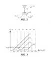
- FIG. 3illustrates the relation between the source-drain current I D and the control gate voltage V CG for four different charges Q 1 -Q 4 that the floating gate may be selectively storing at any one time.
- FIG. 4illustrates an example of an NOR array of memory cells.
- FIG. 5Aillustrates schematically a string of memory cells organized into an NAND string.
- FIG. 5Billustrates an example of an NAND array 200 of memory cells, constituted from NAND strings 50 such as that shown in FIG. 5A .
- FIG. 6illustrates the Read/Write Circuits 270 A and 270 B, shown in FIG. 1 , containing a bank of p sense modules across an array of memory cells.
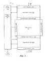
- FIG. 7illustrates schematically a preferred organization of the sense modules shown in FIG. 6 .
- FIG. 8illustrates in more detail the read/write stacks shown in FIG. 7 .
- FIGS. 9 ( 0 )- 9 ( 2 )illustrate an example of programming a population of 4-state memory cells.
- FIGS. 10 ( 0 )- 10 ( 2 )illustrate an example of programming a population of 8-state memory cells.
- FIG. 11illustrates a conventional technique for programming a 4-state memory cell to a target memory state.
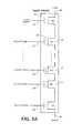
- FIG. 12shows a circuitry detail on how voltages are supplied to word-lines.
- FIG. 13is a block diagram of an exemplary charge pump circuit.
- FIG. 14adds leakage detection circuitry to FIG. 13 .
- FIG. 15illustrates the phases of the exemplary leakage detection operation.
- FIG. 16shows the current path in a calibration process for the word-line leakage process.
- FIG. 17illustrates the phases of the calibration operation.
- FIG. 18shows the distribution of memory cell threshold voltage values to illustrate symptoms of a broken word-line.
- FIG. 19illustrates the variation in the number of programming pulse-verify iterations over different word-lines.
- FIG. 20is a timing diagram for a broken word-line detection routine.
- FIGS. 21A and 21Billustrate differing placements of word-line drivers.
- FIGS. 22 and 23Aare flows for a scan of failed bits in a program operation.
- FIG. 23Bis a flow for a scan of failed bits in a program operation that also includes broken word-line detection.
- FIG. 1 to FIG. 11illustrate example memory systems in which the various aspects of the present invention may be implemented.
- FIG. 1illustrates schematically the functional blocks of a non-volatile memory chip in which the present invention may be implemented.
- the memory chip 100includes a two-dimensional array of memory cells 200 , control circuitry 210 , and peripheral circuits such as decoders, read/write circuits and multiplexers.
- the memory array 200is addressable by word lines via row decoders 230 (split into 230 A, 230 B) and by bit lines via column decoders 260 (split into 260 A, 260 B) (see also FIGS. 4 and 5 .)
- the read/write circuits 270(split into 270 A, 270 B) allow a page of memory cells to be read or programmed in parallel.
- a data I/O bus 231is coupled to the read/write circuits 270 .
- a pageis constituted from a contiguous row of memory cells sharing the same word line.
- block multiplexers 250split into 250 A and 250 B are provided to multiplex the read/write circuits 270 to the individual pages. For example, two pages, respectively formed by odd and even columns of memory cells are multiplexed to the read/write circuits.
- FIG. 1illustrates a preferred arrangement in which access to the memory array 200 by the various peripheral circuits is implemented in a symmetric fashion, on opposite sides of the array so that the densities of access lines and circuitry on each side are reduced in half.
- the row decoderis split into row decoders 230 A and 230 B and the column decoder into column decoders 260 A and 260 B.
- the page multiplexer 250is split into page multiplexers 250 A and 250 B.
- the read/write circuits 270are split into read/write circuits 270 A connecting to bit lines from the bottom and read/write circuits 2703 connecting to bit lines from the top of the array 200 . In this way, the density of the read/write modules, and therefore that of the sense modules 380 , is essentially reduced by one half.
- the control circuitry 110is an on-chip controller that cooperates with the read/write circuits 270 to perform memory operations on the memory array 200 .
- the control circuitry 110typically includes a state machine 112 and other circuits such as an on-chip address decoder and a power control module (not shown explicitly).
- the state machine 112provides chip level control of memory operations.
- the control circuitryis in communication with a host via an external memory controller.
- the memory array 200is typically organized as a two-dimensional array of memory cells arranged in rows and columns and addressable by word lines and bit lines.
- the arraycan be formed according to an NOR type or an NAND type architecture.
- FIG. 2illustrates schematically a non-volatile memory cell.
- the memory cell 10can be implemented by a field-effect transistor having a charge storage unit 20 , such as a floating gate or a dielectric layer.
- the memory cell 10also includes a source 14 , a drain 16 , and a control gate 30 .
- non-volatile solid-state memory devicesThere are many commercially successful non-volatile solid-state memory devices being used today. These memory devices may employ different types of memory cells, each type having one or more charge storage element.
- Typical non-volatile memory cellsinclude EEPROM and flash EEPROM. Examples of EEPROM cells and methods of manufacturing them are given in U.S. Pat. No. 5,595,924. Examples of flash EEPROM cells, their uses in memory systems and methods of manufacturing them are given in U.S. Pat. Nos. 5,070,032, 5,095,344, 5,315,541, 5,343,063, 5,661,053, 5,313,421 and 6,222,762. In particular, examples of memory devices with NAND cell structures are described in U.S. Pat. Nos. 5,570,315, 5,903,495, 6,046,935.
- the memory state of a cellis usually read by sensing the conduction current across the source and drain electrodes of the cell when a reference voltage is applied to the control gate.
- a corresponding conduction current with respect to a fixed reference control gate voltagemay be detected.
- the range of charge programmable onto the floating gatedefines a corresponding threshold voltage window or a corresponding conduction current window.
- the threshold voltage for a given memory state under testis set at the control gate and detect if the conduction current is lower or higher than a threshold current.
- the detection of the conduction current relative to a threshold currentis accomplished by examining the rate the conduction current is discharging through the capacitance of the bit line.
- FIG. 3illustrates the relation between the source-drain current I D and the control gate voltage V CG for four different charges Q 1 -Q 4 that the floating gate may be selectively storing at any one time.
- the four solid I D versus V CG curvesrepresent four possible charge levels that can be programmed on a floating gate of a memory cell, respectively corresponding to four possible memory states.
- the threshold voltage window of a population of cellsmay range from 0.5V to 3.5V. Seven possible memory states “0”, “1”, “2”, “3”, “4”, “5”, “6”, respectively representing one erased and six programmed states may be demarcated by partitioning the threshold window into five regions in interval of 0.5V each.
- Q 4is in a memory state “5”.
- a memory devicemay have memory cells having a threshold window that ranges from ⁇ 1.5V to 5V. This provides a maximum width of 6.5V. If the memory cell is to store 16 states, each state may occupy from 200 mV to 300 mV in the threshold window. This will require higher precision in programming and reading operations in order to be able to achieve the required resolution.
- FIG. 4illustrates an example of an NOR array of memory cells.
- each row of memory cellsare connected by their sources 14 and drains 16 in a daisy-chain manner. This design is sometimes referred to as a virtual ground design.
- the cells 10 in a rowhave their control gates 30 connected to a word line, such as word line 42 .
- the cells in a columnhave their sources and drains respectively connected to selected bit lines, such as bit lines 34 and 36 .
- FIG. 5Aillustrates schematically a string of memory cells organized into an NAND string.
- a pair of select transistors S 1 , S 2controls the memory transistors chain's connection to the external via the NAND string's source terminal 54 and drain terminal 56 respectively.
- the source select transistor S 1when the source select transistor S 1 is turned on, the source terminal is coupled to a source line (see FIG. 5B ).
- the drain select transistor S 2is turned on, the drain terminal of the NAND string is coupled to a bit line of the memory array.
- Each memory transistor 10 in the chainacts as a memory cell. It has a charge storage element 20 to store a given amount of charge so as to represent an intended memory state.
- a control gate 30 of each memory transistorallows control over read and write operations. As will be seen in FIG. 5B , the control gates 30 of corresponding memory transistors of a row of NAND string are all connected to the same word line. Similarly, a control gate 32 of each of the select transistors S 1 , S 2 provides control access to the NAND string via its source terminal 54 and drain terminal 56 respectively. Likewise, the control gates 32 of corresponding select transistors of a row of NAND string are all connected to the same select line.
- FIG. 5Billustrates an example of an NAND array 200 of memory cells, constituted from NAND strings 50 such as that shown in FIG. 5A .
- a bit linesuch as bit line 36 is coupled to the drain terminal 56 of each NAND string.
- a source linesuch as source line 34 is couple to the source terminals 54 of each NAND string.
- the control gates along a row of memory cells in a bank of NAND stringsare connected to a word line such as word line 42 .
- the control gates along a row of select transistors in a bank of NAND stringsare connected to a select line such as select line 44 .
- An entire row of memory cells in a bank of NAND stringscan be addressed by appropriate voltages on the word lines and select lines of the bank of NAND strings.
- the remaining memory transistors in the stringare turned on hard via their associated word lines so that the current flowing through the string is essentially dependent upon the level of charge stored in the cell being read.
- FIG. 6illustrates the Read/Write Circuits 270 A and 270 B, shown in FIG. 1 , containing a bank of p sense modules across an array of memory cells.
- the entire bank of p sense modules 480 operating in parallelallows a block (or page) of p cells 10 along a row to be read or programmed in parallel.
- sense module 1will sense a current I 1 in cell 1
- sense module 2will sense a current I 2 in cell 2
- sense module pwill sense a current I p in cell p, etc.
- the total cell current i TOT for the page flowing out of the source line 34 into an aggregate node CLSRC and from there to groundwill be a summation of all the currents in the p cells.
- a row of memory cells with a common word lineforms two or more pages, where the memory cells in a page are read and programmed in parallel.
- one pageis accessed by even bit lines and the other page is accessed by odd bit lines.
- a page of sensing circuitsis coupled to either the even bit lines or to the odd bit lines at any one time.
- page multiplexers 250 A and 250 Bare provided to multiplex the read/write circuits 270 A and 270 B respectively to the individual pages.
- the blockis a run of the entire row of cells. This is the so-called “all bit-line” architecture in which the page is constituted from a row of contiguous memory cells coupled respectively to contiguous bit lines.
- the blockis a subset of cells in the row. For example, the subset of cells could be one half of the entire row or one quarter of the entire row. The subset of cells could be a run of contiguous cells or one every other cell, or one every predetermined number of cells.
- Each sense moduleis coupled to a memory cell via a bit line and includes a sense amplifier for sensing the conduction current of a memory cell.
- the bank of p sense moduleswill be distributed between the two sets of Read/Write Circuits 270 A and 270 B.
- FIG. 7illustrates schematically a preferred organization of the sense modules shown in FIG. 6 .
- the read/write circuits 270 A and 270 B containing p sense modulesare grouped into a bank of read/write stacks 400 .
- FIG. 8illustrates in more detail the read/write stacks shown in FIG. 7 .
- the architectureis such that each stack of k sense modules is serviced by a common processor 500 in order to save space.
- the common processor 500computes updated data to be stored in the latches located at the sense modules 480 and at the data latches 430 based on the current values in those latches and on controls from the state machine 112 .
- Detailed description of the common processorhas been disclosed in U.S. Patent Application Publication Number: US-2006-0140007-A1 on Jun. 29, 2006, the entire disclosure of which is incorporated herein by reference.
- the entire bank of partitioned read/write stacks 400 operating in parallelallows a block (or page) of p cells along a row to be read or programmed in parallel.
- Each read/write stacksuch as 400 - 1 , essentially contains a stack of sense modules 480 - 1 to 480 - k servicing a segment of k memory cells in parallel.
- the page controller 410provides control and timing signals to the read/write circuit 370 via lines 411 .
- the page controlleris itself dependent on the memory controller 310 via lines 311 .
- Communication among each read/write stack 400is effected by an interconnecting stack bus 431 and controlled by the page controller 410 .
- Control lines 411provide control and clock signals from the page controller 410 to the components of the read/write stacks 400 - 1 .
- the stack busis partitioned into a SABus 422 for communication between the common processor 500 and the stack of sense modules 480 , and a DBus 423 for communication between the processor and the stack of data latches 430 .
- the stack of data latches 430comprises of data latches 430 - 1 to 430 - k , one for each memory cell associated with the stack.
- the I/O module 440enables the data latches to exchange data with the external via an I/O bus 231 .
- the common processoralso includes an output 507 for output of a status signal indicating a status of the memory operation, such as an error condition.
- the status signalis used to drive the gate of an n-transistor 550 that is tied to a FLAG BUS 509 in a Wired-Or configuration.
- the FLAG BUSis preferably precharged by the controller 310 and will be pulled down when a status signal is asserted by any of the read/write stacks.
- a nonvolatile memory in which the memory cells each stores multiple bits of datahas already been described in connection with FIG. 3 .
- a particular exampleis a memory formed from an array of field-effect transistors, each having a charge storage layer between its channel region and its control gate.
- the charge storage layer or unitcan store a range of charges, giving rise to a range of threshold voltages for each field-effect transistor.
- the range of possible threshold voltagesspans a threshold window.
- each resolvable zoneis used to represent a different memory states for a memory cell.
- the multiple memory statescan be coded by one or more binary bits. For example, a memory cell partitioned into four zones can support four states which can be coded as 2-bit data. Similarly, a memory cell partitioned into eight zones can support eight memory states which can be coded as 3-bit data, etc.
- FIGS. 9 ( 0 )- 9 ( 2 )illustrate an example of programming a population of 4-state memory cells.
- FIG. 9 ( 0 )illustrates the population of memory cells programmable into four distinct distributions of threshold voltages respectively representing memory states “0”, “1”, “2” and “3”.
- FIG. 9 ( 1 )illustrates the initial distribution of “erased” threshold voltages for an erased memory.
- FIG. 9 ( 2 )illustrates an example of the memory after many of the memory cells have been programmed. Essentially, a cell initially has an “erased” threshold voltage and programming will move it to a higher value into one of the three zones demarcated by V 1 , V 2 and V 3 .
- each memory cellcan be programmed to one of the three programmed state “1”, “2” and “3” or remain un-programmed in the “erased” state.
- the initial distribution of the “erased” state as shown in FIG. 9 ( 1 )will become narrower and the erased state is represented by the “0” state.
- a 2-bit code having a lower bit and an upper bitcan be used to represent each of the four memory states.
- the “0”, “1”, “2” and “3” statesare respectively represented by “11”, “01”, “00” and “10”.
- the 2-bit datamay be read from the memory by sensing in “full-sequence” mode where the two bits are sensed together by sensing relative to the read demarcation threshold values V 1 , V 2 and V 3 in three sub-passes respectively.
- FIGS. 10 ( 0 )- 10 ( 2 )illustrate an example of programming a population of 8-state memory cells.
- FIG. 10 ( 0 )illustrates the population of memory cells programmable into eight distinct distributions of threshold voltages respectively representing memory states “0”-“7”.
- FIG. 10 ( 1 )illustrates the initial distribution of “erased” threshold voltages for an erased memory.
- FIG. 10 ( 2 )illustrates an example of the memory after many of the memory cells have been programmed. Essentially, a cell initially has an “erased” threshold voltage and programming will move it to a higher value into one of the three zones demarcated by V 1 -V 7 .
- each memory cellcan be programmed to one of the seven programmed state “1”-“7” or remain un-programmed in the “erased” state.
- the initial distribution of the “erased” state as shown in FIG. 10 ( 1 )will become narrower and the erased state is represented by the “0” state.
- a 3-bit code having a lower bit and an upper bitcan be used to represent each of the four memory states.
- the “0”, “1”, “2”, “3”, “4”, “5”, “6” and “7” statesare respectively represented by “111”, “011”, “001”, “101”, “100”, “000”, “010” and “110”.
- the 3-bit datamay be read from the memory by sensing in “full-sequence” mode where the three bits are sensed together by sensing relative to the read demarcation threshold values V 1 -V 7 in seven sub-passes respectively.
- One method of programming a pageis full-sequence programming. All cells of the page are initially in an erased state. Thus, all cells of the page are programmed in parallel from the erased state towards their target states. Those memory cells with “1” state as a target state will be prohibited from further programming once their have been programmed to the “1” state while other memory cells with target states “2” or higher will be subject to further programming. Eventually, the memory cells with “2” as a target state will also be locked out from further programming. Similarly, with progressive programming pulses the cells with target states “3”-“7” are reached and locked out.
- FIG. 11illustrates a conventional technique for programming a 4-state memory cell to a target memory state.
- Programming circuitsgenerally apply a series of programming pulses to a selected word line. In this way, a page of memory cells whose control gates are coupled to the word line can be programmed together.
- the programming pulse train usedmay have increasing period or amplitude in order to counteract the accumulating electrons programmed into the charge storage unit of the memory cell.
- a programming voltage V PGMis applied to the word line of a page under programming.
- the programming voltage V PGMis a series of programming voltage pulses in the form of a staircase waveform starting from an initial voltage level, V PGM0 .
- Each cell of the page under programmingis subject to this series of programming voltage pulses, with an attempt at each pulse to add incremental charges to the charge storage element of the cell.
- the cellis read back to determine its threshold voltage.
- the read back processmay involve one or more sensing operation. Programming stops for the cell when its threshold voltage has been verified to fall within the threshold voltage zone corresponding to the target state. Whenever a memory cell of the page has been programmed to its target state, it is program-inhibited while the other cells continue to be subject to programming until all cells of the page have been program-verified.
- word-line defectscan include both leaky word-lines and broken word-lines. Both of these are consider below, with word-line leakage discussed first.
- the detection of word-line leakagecan typically only be done at test time for the memory chip by applying high voltage levels directly to a device's pins and then measuring the current/voltage levels at the pins.
- Therequires the use of tester device and cannot be done after the memory chip is assembled as part of a device. This means that the word-lines cannot then be checked after device burn-in.
- the techniques presented hereallow for an on-chip means of detecting word-line leakage.
- the techniques presentedallow for the detection of leakage on a word-line while the word-line has a high voltage applied internally.
- a capacitive voltage divideris used to translate the high voltage drop to low voltage drop that can be compared with a reference voltage to determine the voltage drop due to leakage.
- the next sectionwill present a related on-chip self calibration method that can help assure the accuracy of this technique for detecting leakage limit.
- the word-line leakagecould be on the order 100 nA at high voltage stress such as 10 to 20 Volts.
- the difficulty of detecting such a small current at high voltageis due to the current NAND architecture.
- the planes of a memory circuitcan have on the order of several thousand blocks, one of which is shown at 610 and each block may have several dozen word-lines, three of which are explicitly shown as WLn ⁇ 1 615 , WLn 613 , and WLn+1 611 .
- the high voltageis normally applied on the selected word-line, such as WLn 613 during program and read operations.
- the NAND architecturealso requires to have the least area penalty of the wordline voltage drivers.
- the driveris typically connected to the wordlines from one end of the wordline array. If the architecture allow the connection to wordlines from both ends, wordline leakage or breakage can be detected by sending a known current from one end and detect the same current from the other end.
- the high voltage VPGMis generated by a pump (discussed below with respect to FIG. 13 ) and supplied to the first decoding CGN block 601 , represented here as a switch.
- CGN block 601is a block to supplied the various (typically 3 to 5 different kinds) of voltages according to the mode of operations for each global control gate (CG) lines.
- CGglobal control gate
- Three of the CG lines ( 621 , 623 , 625 )are shown explicitly, corresponding the shown word-lines.
- the CG lines(as many as the number of word-lines in each block) will rout to the row (block) decoder of the memory array.
- each blockis decoded with a local pump.
- a logic signalwill enable the local pump to apply a high passing voltage transferG on the gates of the passing transistors (here represented by 631 , 633 , and 635 for the three shown word-lines) in the row decoder.
- the high voltage on the correspond global CGwill be transferred to the word-line of the selected block.
- word-line WLn 613is shown connected to receive VPGM, with the two adjoining word-lines ( 611 , 615 ) taken to ground (or more generally the low voltage level), corresponding to the word-line to word-line leakage test pattern discussed below.
- the word-linescan have different bias topology according to the defects to be detected.
- all the word-linescan be biased to high voltage of same levels, with the substrate at ground.
- the word-lines in the blockwill be biased alternatively at high voltage (VPGM) and 0 volts, as shown in FIG. 12 .
- the worst parasitic capacitancewill be from the latter case.
- FIG. 12also shows some exemplary, estimated values for the parasitic capacitances involved. From the high voltage pump to the CON (high voltage to multiplexing block) in a 64 word-line architecture the contribution is roughly 50. Inside the CGN block, the loading will be 4 pF. Each global top metal routing from CON block to the row decoder at the edge of the memory array is 4 pF. The junction capacitance of one plane is 1 pF. Each local word-line has 2 pF.
- the voltage drop required for the detectioncan be reduced to 100 mV, with the corresponding detection time reduced to around 500 us.
- Thiscan be used for in-field detection operations. In one preferred set of embodiments, this could be executed before each erase operation.
- the detectioncan either be included as part of the erase operation sequence or can be done before the erase in response to an instruction issued by the controller. If a block fails, the controller can then remove it from the pool of usable blocks.
- the discharge and testing timewill depend on the parasitic capacitance of the CG routing. Because of this, one set of preferred embodiments has an on-chip calibration mechanism built in to memory chip so that the precise leakage criteria can be used for detection and the test time can be automatically adjusted according to the chip architecture, word-line voltage stress topology, number of planes, and any other contributing factors. This calibration system is discussed further in the next section.
- a normal high voltage pumpis normally regulated by a resistor divider, such as shown in FIG. 13 .
- the high voltage VPGMwill be divided by the resistors 645 and 647 , connected to ground (or more generally the low voltage level) through the switch SW 1 649 , and the compare point voltage for the amp 643 will be voltage reference vref of usually around 1.2 volts.
- the resistor chainnormally will have a leakage current of 10 uA level.
- the differential amplifier or comparator 643will be used to output a digital voltage flag-pump which will be used to control the pump clock. When the pump is pumped to the target level, the flag_pump will be low to turn off the pump clock. When the high voltage is dropped below certain level, the flag_pump signal will go high to enable the pump clock and turn on the pump to supply high voltage.
- charge pumpsMore detail on charge pumps can be found, for example, in “Charge Pump Circuit Design” by Pan and Samaddar, McGraw-Hill, 2006, or “Charge Pumps: An Overview”, Pylarinos and Rogers, Department of Electrical and Computer Engineering University of Toronto, available on the webpage “www.eecg.toronto.edu/ ⁇ kphang/ece1371/chargepumps.pdf”. Further information on various other charge pump aspects and designs can be found in U.S. Pat. Nos.
- a detection principle similar to FIG. 12can be used to detect the voltage change on the large parasitic high voltage node. Since the leakage is in the order of 100 nA, a new way to divide the high voltage to low voltage has to be used.
- a comparatoris normally built with a low voltage supply for saving Icc current.
- a capacitive dividerhas the advantage of no leakage current.
- the difficulty with a capacitive voltage divideris that the initial voltage at the detecting point has to be accurately set.
- a new set of differential amplifiers or comparators 653is added for the word-line leakage detection on top of that of regulator 643 .
- the comparison voltage verf 1can be set by a digital to analog converter voltage circuit 651 , whose input can be set according to the device. (In an alternate embodiment, this could also be set as part of the calibration process.)
- a switch transistor SW 2 659will be used to initialize the compare nodes at the same voltage level of the regulating level.
- the capacitors C 1 655 and C 2 657are the capacitive voltage divider. A ratio is 1:1 can be used.
- the detection point voltage Vmidwill have a delta of
- ⁇ ⁇ ⁇ Vmid⁇ ⁇ ⁇ V output ⁇ ( C 1 C 1 + C 2 ) where ⁇ V output is the high voltage drop due to leakage.
- the word-line leakage detectionis a 3 step detection process, as shown in FIG. 15 where the level on the word-line is shown at 705 .
- the far side of word-line which located far from the word-line driver sidemay take a longer time to charge (as shown as the dotted line 707 ).
- the high voltagecan also pumped in two stages: first pumped to a intermediate voltage with another stronger pump, then use the high voltage pump to charge the word-line to a higher level.
- the detection point Vmidis also initialized by turning on SW 2 .
- the voltage dropwill be measured by the comparator 653 .
- the discharge timewill depend on the total parasitic capacitance and the targeted detecting leakage current. (For more accurate leakage detection, a self calibration circuits will be introduced in the next section.)
- the mid point voltagewill be compared with the vref 1 to generate the signal Pass or Fail (P/F).
- the vref 1 voltageis generated from an analog voltage generator 651 which can deliver a voltage between 0 to 1.2 V with 50 mV resolution, as an example.
- the whole blockWhen word-line leakage is detected, the whole block will typically be marked as a bad block which will not be used. Any valid data could be transferred as needed to another block, although, as noted above, in a preferred set of embodiments the leakage detection process is executed as part of an erase process. In other cases, for example when the memory has a NOR architecture, single defective word-line could be mapped out.
- the word-line leakage detection timedepends on the parasitic capacitance, which can have large variations depending on architecture, voltage bias topology, and the number of planes. It is, consequently, preferable to have a method to calibrate the discharge time with a known leakage current.
- An on-chip self calibration algorithmis described in this section. A convenient way of accomplishing this, without needing to add extra elements, is to utilize a known current in the regulator to calibrate the detection time.
- FIG. 16shows the same elements as in FIG. 14 , but as shown in FIG. 16 , the resistor voltage divider is used to discharge the high voltage during the calibration process, as shown by the current path Idis 673 .
- These elementsare again preferably implemented as peripheral circuitry on the memory chip and the path tested in the calibration process should match the path actually used for detection of leakage.
- a good blockshould be used to determine the characteristics of a block without any word-line leakage.
- the good blockmay be determined by its program characteristics or from other some other good block check. For example, data corresponding to the highest state can be programmed and read back to see if it is correct.
- wordline leakagewill often not have begun to manifest itself and the location of a good block is generally easy.
- the calibrationis similar with the real leakage test and can be performed in 3 stages, as shown in FIG. 17 .
- a first phaseprecharges the word-lines of the test block to the targeted voltage level pattern by turning on the high voltage pump, the CGN voltage selection circuits and the row decoder for selected block.
- the high voltageis regulated by the resistor voltage divider and the comparator to enable pump clock.
- SW 1 and SW 2are both on, as shown respectively at 801 and 803 .
- the word-linescharge up as shown at 805 and 807 , respectively corresponding to 705 and 707 of FIG. 15 .
- the discharge phasewill be different from the normal word-line leakage test illustrated in FIG. 15 .
- the high voltage VPGMwill be discharged through the resistor chain with a fixed leakage current along the path 673 of a discharge current of I dis on the order of 10 ⁇ A.
- the amp output Pass/Failwill feed back to turn off SW 1 .
- a timercan start counting the time from the start of the discharge phase till the comparator flipping of P/F from pass to fail.
- the timercan be multiplied by a factor of 2 (such as 128) to set the timer counter for detecting targeted leakage current. For example, if the resistor leak 10 ⁇ A, the timer multiplying 128 will give the detecting current of 78 nA. (Other factors could also be used, but factors of two are readily implemented, as an easy way to multiply by 2 is to perform a shift of binary digits to the higher bits.)
- the calibrationonly needs to be done once for a given voltage topology during die sort test.
- the timer digitscan then be fixed and stored, for example, in a ROM fuse block. During power on read, the timer digits will be read out to registers and controls the word-line leakage test. For a different stress topology, a new calibration is needed, since the parasitic capacitance is changed. After each calibration, a corresponding timer parameter can be acquired and saved in the ROM flash memory.
- the word-line leakagecan be used during manufacture test, or for in-field tests once the device is out of factory.
- the micro-controllerwould issue the command to do the word-line leakage test in the user application.
- a convenient time to do the leakage testis before the erase operation, since the program disturb incurred during the leakage test can be eliminated by the subsequent erase operation.
- This sectionlooks at the detection of broken word-lines. As device size decreases, in addition to the likely increase in leaky word-lines, the occurrence of broken word-lines is also likely to become more common. A broken word-line will have a high resistive connection across the break, because of which the cells on far end of the word-line (on the other side of the break from the word-line driver) will see a voltage drop during both program and verify operations. This will lead to programming pulses having a lower amplitude, so that cells will be programmed less; but as the verify level is also lowered, these under-programmed cells may still verify.
- the threshold voltage distribution for the broken word-linewill show two humps, one corresponding to cells one side of the break and the other corresponding to cells on the other side of the break.
- the method described in this sectioncan be used to identify the broken word-line failure and recover the data of the broken word-line.
- Yet another method of identifying broken word-linesis to screen out the failure during die-sort.
- a whole blockis programmed and then read back.
- the lower page of each word-linecan be programmed and read twice.
- One readis done with a normal read point and another with a raised read point, similar to a forbidden zone read described in the last paragraph.
- the results of the two sensing operationsare then compared using a test-mode command sequence.
- thiswill only pick up the word-line breakage that manifests itself at test time, when the symptoms often do not show up until the device has operated over some time.
- the word-line already exhibits breakageit may not demonstrate this on every program cycle and, consequently, may be missed in a single test operation.
- FIG. 18shows the threshold distribution of a block of a memory word-line by word-line, for the a 64 word-line example.
- the distributions for three statesare shown at 901 , 903 , and 905 .
- theseform three well defined and separated humps, where the highest two states, for example, are separated by the region between 923 and 925 .
- those cells on the far side of the break from the word-line driverwill be shifter to lower threshold values, as shown at 911 , 913 , and 915 .
- FIG. 19shows the number of pulse-verify iterations, or loop count, for each word-line to program, in this example, lower page into a 64 word-line block.
- the loop countfluctuates over the different word-lines by several counts. These variations can reflect fluctuations due to the design particulars, such as whether it is an edge wordline or a central wordline, or how many erase-program cycle the wordline has experienced, as well as process variations. In the case of WL 50 , the loop count is noticeable higher than the other fluctuations, indicating what may likely be a broken wordline, although further tests would be used to confirm whether it is actually broken or this is just a false alarm.
- the techniques presented heremake it possible to detect broken word-line failure by comparing the program loop count for the cells located on two different sides of the fault.
- the cells along word-lineare programmed and it determined how it takes the cells of different groups or subsets of these cells to verify as programmed to target state, such as writing all the cells to have a programmed lower page.
- a group with cells on the far side of a break from the word-line driverwill take longer to program than a group that has all of its cells between the driven and the break.
- memory cellsare typically programmed using an alternating pulse-verify algorithm, this can be done by keep track of the number of pulses, or loop count, needed by the different groups or just the difference in the number required.
- the programmingcan be done for all of the cells along word-line or some portion of them, such as for system that program the odd bit lines and even bit lines separately.
- the subsets of cells that have their loop counts comparedare the contiguous subset of cells of the segment of one end of the word-line and the segment at the other end of the word-line. More generally other subsets of the cells could be used, but by looking at segments from the two ends of the word-line any break should be caught without having to do multiple comparisons of groups' loop counts; and looking at segments of the word-line is generally more readily implementable in the exemplary architecture than if the groups are formed from non-contiguous subsets of the cells, overlapping subsets, or some combination of these.
- Memory devicesoften already include a scan to check for failed memory bits when programming.
- the exemplary embodimentincorporates the broken word-line detection into such a routine, which can have several advantages.
- the broken word-line detectionis incorporated into a failed bit detection that is done during the last few program loops and which counts the failed bits segment by segment, the word-lines being subdivided into multiple segments.
- each the segmentscan be taken to correspond to one or several adjacent ones of the read/write stacks as shown in FIG. 7 . While this scan is ongoing, the scan result of first physical segment and last physical segment on the ends of the world-line can be monitored. When the failed bit count for either one of these two segments end goes below a fixed (in this example) criterion, a signal is latched high to mark the passing of the one segment.
- An up-countercan then be triggered when the first of these segments passes the scan.
- the counteris then stopped when the slower of the two segments passes scan operation.
- the output of the up-counteris compared to the fixed criterion. If the count is higher than the criterion, a signal can be latched high to indicate that a broken word-line has been detected.
- the up-countercan be implemented on the state machine ( 112 FIG. 8 ). As the up-counter can simply count the program look stating when the one segment passes the its write criteria, the on-chip state machine will typically be able to keep count of the program loops, so this adds an additional count for it to maintain.
- FIG. 20The process can be illustrated by the diagram of FIG. 20 that shows the waveforms for some of the signals involved in this scheme.
- OPCis the program loop count, corresponding the iteration in the pulse-verify sequence.
- OPC_DIFFis the up-counter for counting the program loop difference.
- SEG 1 _COMPis the latched signal to indicate the passing point of first of segments.
- LASTSEG_COMis the latched signal to indicate the passing point of the last segment.
- FIG. 20picks up the program process after n ⁇ 1 loops have been completed at time t 0 .
- SEG 1 _COMP, LASTSEG_COM, and the BROKEN_WL signalsare all low and the up-counter is initialized to 0.
- t 1corresponding loop count n
- a first one of the end segments(here taken as the first segment) reaches its passing point and SEG 1 _COMP goes high and the up-counter starts, as shown as OPC_DIFF.
- OPC_DIFFcontinues to increment up with the loop count until the other of the end segments (here the last segment) passes at t 4 , corresponding to loop count n+3.
- the signal BROKEN_WLthen goes high when OPC_DIFF>F_OPC_DIFF.
- FIGS. 21A and 21BOne complexity that can involved in implementing the above described scheme is the case when the architecture use two sided word-line drivers, placing drivers on both sides of the array (such as would be in the row decoders 230 A and 230 B of FIG. 1 ). This can be illustrated by FIGS. 21A and 21B .
- the word-line WL 901 Ahas the driver 905 A to the left, closest to the driver.
- the last segment along the word-line 901 Ais on the other side of the break 903 A from the driver 905 A and will consequently see lowered voltage levels and be slower than the first segment.
- FIG. 21Bthe word-line driver 905 B is to the right and closest to the last segment close to the last segment along word-line 901 B.
- the first segmentwill be on the far side of the break 903 B, receive lowered voltages and the first segment will be slower than the last segment. Under such an arrangement, it cannot be assumed that the last segment will pass last, since it may be closest to the driver.
- the segmented bitscanis include as part of a normal program algorithm.
- the broken wordline detection schemecan be integrated into a similar state machine to that for segmented bitscan without the detection.
- the segmented bitscanis not terminated because the first segment should also be checked to see at which program loop it passed the program.
- U.S. Pat. No. 7,440,319if any segment does not finish programming, it is counted as the whole page of data not being finished, and terminates as soon as one segment fails.
- the broken word line detectionis incorporated, the exemplary embodiment will go through the last segment and continue to the first segment regardless of whether the last segment fails or passes.
- the failed bit scan routineis also modified to include the broken word-line detection process.
- the exemplary embodimentincludes redundant columns, so the number of failed bits allowable in the other sections depends not just on the number of failures there, but also on the number of redundant bits available in the last segment that could be substituted in for failed bits in the first segment. For example, the failed bit count of last segment and first segment are added together and then compared to the criterion in order to determine pass/fail status for first segment.
- the flowwill be modified such that the failed bit count for failed segment can be compared to the failed bit criterion in order to determine pass/fail for first segment.
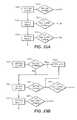
- FIGS. 23A and 23Bshow the comparison between a counting scheme that includes neither broken word-line detection nor the process of FIG. 22 ( FIG. 23A ) and the exemplary embodiment that includes both ( FIG. 23B ).
- the first of theseis schematically illustrated in FIG. 23A , which starts at 1001 with a scan of the last segment, including the redundant columns (ColRD), which is then compared against its criteria at 1003 to determine if the last segment has failed. In this embodiment, the process continues (pass or fail) on to the first segment scan at 1005 .
- the criteria used at 1007 for the first segmentis compared not just to the scan result for the first segment itself, but also takes into account the number of redundant columns (ColRD) available. If the 1st segment test at 1007 is passed, the flow similarly continues on to the second segment at 1009 and 1011 , and so on through the other segments.
- the scan circuitwill need to be modified such that it continues to scan the first segment even if the last segment fails.
- the diagram of FIG. 23Bshows a scan algorithm to account for this and that includes the broken word-line check.
- the scan of the last segment 1051is compared against the corresponding criteria at 1053 .
- the processwill again continue on the scan of the first segment, 1055 , regardless of whether or nor the last segments passes or fails, going from 1053 to 1055 if 1053 fails. If 1053 passes, the flow will now go to 1059 as well as 1055 .
- a broken wordlinedoes not necessarily fail to program When the segment is far from the wordline driver, it will be slower to program, by not necessarily impossible. Hence, it may eventually pass, but it is needed to determine the programming speed at both ends of the wordline, which may differ significantly, in order confirm that a wordine is actually broken.
- the last segmentWhen the last segment passes, it will trigger the OPC_DIFF block, as will the first segment from 1057 , with the first of these to pass starting the counting and the last to pass stopping it in order to count the difference.
- the determination of wordline breakage at 1059will be based difference from the first segment (alone, without redundant column considerations) and last segment loop counts.
- 1061is the bitsean for program status as before, where columns of the first segment may have defective columns replaced by redundant columns (from the last segment). Because of this, both 1057 and 1061 are included in the flow. The process then continues on to the second segment at 1063 , 1065 and other segments as before.
- the number of defective devices due to broken word-line failurescan be reduced without performance penalty. Further, as this is included as part of the programming routine, it is able to pick up breaks that only manifest themselves after a device is shipped. This allows it to be a more efficient and accurate method of broken word-line detection compared to the other methods due to the fact that it is in-field detection. It can reduce the program loop count variation due to word-line-word-line, block-block and chip-chip variations with no performance penalty and avoids time-consuming die-sort screens.
Landscapes
- Read Only Memory (AREA)
Abstract
Description
where ΔVoutputis the high voltage drop due to leakage.
Claims (11)
Priority Applications (7)
| Application Number | Priority Date | Filing Date | Title |
|---|---|---|---|
| US12/833,167US8305807B2 (en) | 2010-07-09 | 2010-07-09 | Detection of broken word-lines in memory arrays |
| EP11729863.8AEP2591472B1 (en) | 2010-07-09 | 2011-06-24 | Detection of broken word-lines in memory arrays |
| KR1020137003380AKR101692580B1 (en) | 2010-07-09 | 2011-06-24 | Detection of broken word-lines in memory arrays |
| JP2013518512AJP2013533572A (en) | 2010-07-09 | 2011-06-24 | Detection of corrupted word lines in memory arrays |
| CN201180034019.2ACN103003886B (en) | 2010-07-09 | 2011-06-24 | The detection method of storage component part and fracture wordline thereof |
| PCT/US2011/041890WO2012005993A1 (en) | 2010-07-09 | 2011-06-24 | Detection of broken word-lines in memory arrays |
| TW100124089ATW201216287A (en) | 2010-07-09 | 2011-07-07 | Detection of broken word-lines in memory arrays |
Applications Claiming Priority (1)
| Application Number | Priority Date | Filing Date | Title |
|---|---|---|---|
| US12/833,167US8305807B2 (en) | 2010-07-09 | 2010-07-09 | Detection of broken word-lines in memory arrays |
Publications (2)
| Publication Number | Publication Date |
|---|---|
| US20120008405A1 US20120008405A1 (en) | 2012-01-12 |
| US8305807B2true US8305807B2 (en) | 2012-11-06 |
Family
ID=44627973
Family Applications (1)
| Application Number | Title | Priority Date | Filing Date |
|---|---|---|---|
| US12/833,167Expired - Fee RelatedUS8305807B2 (en) | 2010-07-09 | 2010-07-09 | Detection of broken word-lines in memory arrays |
Country Status (7)
| Country | Link |
|---|---|
| US (1) | US8305807B2 (en) |
| EP (1) | EP2591472B1 (en) |
| JP (1) | JP2013533572A (en) |
| KR (1) | KR101692580B1 (en) |
| CN (1) | CN103003886B (en) |
| TW (1) | TW201216287A (en) |
| WO (1) | WO2012005993A1 (en) |
Cited By (25)
| Publication number | Priority date | Publication date | Assignee | Title |
|---|---|---|---|---|
| US20140254264A1 (en)* | 2013-03-08 | 2014-09-11 | Sandisk Technologies Inc. | Defect Or Program Disturb Detection With Full Data Recovery Capability |
| US20150117105A1 (en)* | 2013-10-31 | 2015-04-30 | Bong-Kil Jung | Nonvolatile memory device and method detecting defective word line |
| US9129701B2 (en) | 2013-12-19 | 2015-09-08 | Sandisk Technologies Inc. | Asymmetric state detection for non-volatile storage |
| US9305651B1 (en)* | 2014-09-22 | 2016-04-05 | Sandisk Technologies Inc. | Efficient wide range bit counter |
| US9330776B2 (en) | 2014-08-14 | 2016-05-03 | Sandisk Technologies Inc. | High voltage step down regulator with breakdown protection |
| US9330783B1 (en) | 2014-12-17 | 2016-05-03 | Apple Inc. | Identifying word-line-to-substrate and word-line-to-word-line short-circuit events in a memory block |
| US9390809B1 (en) | 2015-02-10 | 2016-07-12 | Apple Inc. | Data storage in a memory block following WL-WL short |
| US9406393B2 (en) | 2014-08-25 | 2016-08-02 | Samsung Electronics Co., Ltd. | Nonvolatile memory devices and program verification methods using one verification voltage to verify memory cells having different target states |
| US9437321B2 (en) | 2014-10-28 | 2016-09-06 | Sandisk Technologies Llc | Error detection method |
| US9529663B1 (en) | 2015-12-20 | 2016-12-27 | Apple Inc. | Detection and localization of failures in 3D NAND flash memory |
| US9570160B1 (en) | 2015-10-29 | 2017-02-14 | Sandisk Technologies Llc | Non-volatile storage system with defect detetction and early programming termination |
| US9595343B1 (en) | 2016-06-05 | 2017-03-14 | Apple Inc. | Early prediction of failure in programming a nonvolatile memory |
| KR101736457B1 (en) | 2011-07-12 | 2017-05-17 | 삼성전자주식회사 | Nonvolatile memory device, erasing method of nonvolatile memory device, operating method of nonvolatile memory device, memory system including nonvolatile memory device, memory system including nonvolatile memory device, operating method of memory system, and memory card and solid state drive including nonvolatile memory device |
| US9698676B1 (en) | 2016-03-11 | 2017-07-04 | Sandisk Technologies Llc | Charge pump based over-sampling with uniform step size for current detection |
| US9711227B1 (en) | 2016-04-28 | 2017-07-18 | Sandisk Technologies Llc | Non-volatile memory with in field failure prediction using leakage detection |
| US9940271B2 (en) | 2013-12-31 | 2018-04-10 | Sandisk Technologies Llc | Methods for using pulse signals in memory circuits |
| US9996417B2 (en) | 2016-04-12 | 2018-06-12 | Apple Inc. | Data recovery in memory having multiple failure modes |
| US10147495B2 (en) | 2016-11-30 | 2018-12-04 | Samsung Electronics Co., Ltd. | Nonvolatile memory device generating loop status information, storage device including the same, and operating method thereof |
| US10249382B2 (en) | 2017-08-22 | 2019-04-02 | Sandisk Technologies Llc | Determination of fast to program word lines in non-volatile memory |
| US10755787B2 (en) | 2018-06-28 | 2020-08-25 | Apple Inc. | Efficient post programming verification in a nonvolatile memory |
| US10762967B2 (en) | 2018-06-28 | 2020-09-01 | Apple Inc. | Recovering from failure in programming a nonvolatile memory |
| US10915394B1 (en) | 2019-09-22 | 2021-02-09 | Apple Inc. | Schemes for protecting data in NVM device using small storage footprint |
| US10936455B2 (en) | 2019-02-11 | 2021-03-02 | Apple Inc. | Recovery of data failing due to impairment whose severity depends on bit-significance value |
| US11550657B1 (en) | 2021-09-01 | 2023-01-10 | Apple Inc. | Efficient programming schemes in a nonvolatile memory |
| US12040031B2 (en) | 2022-04-15 | 2024-07-16 | Western Digital Technologies, Inc. | Non-volatile memory with autonomous cycling |
Families Citing this family (51)
| Publication number | Priority date | Publication date | Assignee | Title |
|---|---|---|---|---|
| US8305807B2 (en)* | 2010-07-09 | 2012-11-06 | Sandisk Technologies Inc. | Detection of broken word-lines in memory arrays |
| US8432732B2 (en) | 2010-07-09 | 2013-04-30 | Sandisk Technologies Inc. | Detection of word-line leakage in memory arrays |
| US8514630B2 (en) | 2010-07-09 | 2013-08-20 | Sandisk Technologies Inc. | Detection of word-line leakage in memory arrays: current based approach |
| US8379454B2 (en) | 2011-05-05 | 2013-02-19 | Sandisk Technologies Inc. | Detection of broken word-lines in memory arrays |
| US8775901B2 (en) | 2011-07-28 | 2014-07-08 | SanDisk Technologies, Inc. | Data recovery for defective word lines during programming of non-volatile memory arrays |
| US8750042B2 (en) | 2011-07-28 | 2014-06-10 | Sandisk Technologies Inc. | Combined simultaneous sensing of multiple wordlines in a post-write read (PWR) and detection of NAND failures |
| US8717010B2 (en) | 2011-08-19 | 2014-05-06 | Infineon Technologies Ag | Magnetic position sensors, systems and methods |
| US8730722B2 (en) | 2012-03-02 | 2014-05-20 | Sandisk Technologies Inc. | Saving of data in cases of word-line to word-line short in memory arrays |
| JP2013229080A (en)* | 2012-04-26 | 2013-11-07 | Toshiba Corp | Semiconductor memory device and test method for the same |
| US8681548B2 (en) | 2012-05-03 | 2014-03-25 | Sandisk Technologies Inc. | Column redundancy circuitry for non-volatile memory |
| US8914708B2 (en) | 2012-06-15 | 2014-12-16 | International Business Machines Corporation | Bad wordline/array detection in memory |
| US9810723B2 (en) | 2012-09-27 | 2017-11-07 | Sandisk Technologies Llc | Charge pump based over-sampling ADC for current detection |
| US9164526B2 (en) | 2012-09-27 | 2015-10-20 | Sandisk Technologies Inc. | Sigma delta over-sampling charge pump analog-to-digital converter |
| US9490035B2 (en) | 2012-09-28 | 2016-11-08 | SanDisk Technologies, Inc. | Centralized variable rate serializer and deserializer for bad column management |
| KR102154296B1 (en)* | 2012-12-18 | 2020-09-14 | 삼성전자 주식회사 | A driving method of nonvolatile memory device using variable resistive element and the nonvolatile memory device |
| US9070449B2 (en) | 2013-04-26 | 2015-06-30 | Sandisk Technologies Inc. | Defective block management |
| US10083069B2 (en) | 2013-06-27 | 2018-09-25 | Sandisk Technologies Llc | Word line defect detection and handling for a data storage device |
| US9455048B2 (en) | 2013-06-28 | 2016-09-27 | Sandisk Technologies Llc | NAND flash word line management using multiple fragment pools |
| US9165683B2 (en) | 2013-09-23 | 2015-10-20 | Sandisk Technologies Inc. | Multi-word line erratic programming detection |
| EP3104857A4 (en) | 2014-02-14 | 2017-10-11 | The Regents of The University of California | Cyclic peroxides as prodrugs for selective delivery of agents |
| US9484086B2 (en) | 2014-07-10 | 2016-11-01 | Sandisk Technologies Llc | Determination of word line to local source line shorts |
| US9514835B2 (en) | 2014-07-10 | 2016-12-06 | Sandisk Technologies Llc | Determination of word line to word line shorts between adjacent blocks |
| US9460809B2 (en) | 2014-07-10 | 2016-10-04 | Sandisk Technologies Llc | AC stress mode to screen out word line to word line shorts |
| US9443612B2 (en) | 2014-07-10 | 2016-09-13 | Sandisk Technologies Llc | Determination of bit line to low voltage signal shorts |
| US9240249B1 (en) | 2014-09-02 | 2016-01-19 | Sandisk Technologies Inc. | AC stress methods to screen out bit line defects |
| US9202593B1 (en) | 2014-09-02 | 2015-12-01 | Sandisk Technologies Inc. | Techniques for detecting broken word lines in non-volatile memories |
| US9449694B2 (en) | 2014-09-04 | 2016-09-20 | Sandisk Technologies Llc | Non-volatile memory with multi-word line select for defect detection operations |
| US9934872B2 (en) | 2014-10-30 | 2018-04-03 | Sandisk Technologies Llc | Erase stress and delta erase loop count methods for various fail modes in non-volatile memory |
| US9552885B2 (en)* | 2014-12-10 | 2017-01-24 | Sandisk Technologies Llc | Partial block erase for open block reading in non-volatile memory |
| CN104535885B (en)* | 2015-01-05 | 2018-03-06 | 武汉新芯集成电路制造有限公司 | The localization method of word line leakage point |
| US9543023B2 (en) | 2015-01-23 | 2017-01-10 | Sandisk Technologies Llc | Partial block erase for block programming in non-volatile memory |
| US9535787B2 (en) | 2015-02-12 | 2017-01-03 | International Business Machines Corporation | Dynamic cache row fail accumulation due to catastrophic failure |
| US9899102B2 (en)* | 2015-03-31 | 2018-02-20 | SK Hynix Inc. | Semiconductor device and operating method thereof |
| US9659666B2 (en) | 2015-08-31 | 2017-05-23 | Sandisk Technologies Llc | Dynamic memory recovery at the sub-block level |
| US9548105B1 (en)* | 2015-10-29 | 2017-01-17 | Sandisk Technologies Llc | Enhanced post-write read for 3-D memory |
| JP6725362B2 (en)* | 2016-08-19 | 2020-07-15 | キオクシア株式会社 | Semiconductor memory device and memory system |
| US10074440B2 (en) | 2016-10-28 | 2018-09-11 | Sandisk Technologies Llc | Erase for partially programmed blocks in non-volatile memory |
| KR102267046B1 (en)* | 2017-03-29 | 2021-06-22 | 삼성전자주식회사 | Storage device and bad block assigning method thereof |
| KR102386242B1 (en)* | 2017-11-14 | 2022-04-12 | 삼성전자주식회사 | Memory device including a circuit for detecting word line defect which is independent from power supply voltage variation, and operating method of the memory device |
| CN109979521B (en)* | 2017-12-28 | 2021-03-02 | 长鑫存储技术有限公司 | Detection circuit and memory using same |
| TWI676986B (en)* | 2019-03-15 | 2019-11-11 | 華邦電子股份有限公司 | Memory chip and control method thereof |
| KR20210119632A (en)* | 2020-03-25 | 2021-10-06 | 에스케이하이닉스 주식회사 | Memory device and operating method thereof |
| US11315647B2 (en)* | 2020-05-01 | 2022-04-26 | Micron Technology, Inc. | Defect detection during program verify in a memory sub-system |
| KR102821742B1 (en)* | 2020-06-09 | 2025-06-18 | 에스케이하이닉스 주식회사 | Storage device and operating method thereof |
| US11579968B2 (en) | 2020-08-26 | 2023-02-14 | Micron Technology, Inc. | Efficient management of failed memory blocks in memory sub-systems |
| US11289171B1 (en)* | 2020-10-02 | 2022-03-29 | Sandisk Technologies Llc | Multi-level ultra-low power inference engine accelerator |
| US11380408B2 (en)* | 2020-11-30 | 2022-07-05 | Micron Technology, Inc. | Selective overdrive of supply voltage to primary switch for programming memory cells |
| US11756612B2 (en)* | 2021-03-26 | 2023-09-12 | Micron Technology, Inc. | All levels dynamic start voltage programming of a memory device in a memory sub-system |
| US11521686B2 (en)* | 2021-03-31 | 2022-12-06 | Sandisk Technologies Llc | Memory apparatus and method of operation using state bit-scan dependent ramp rate for peak current reduction during program operation |
| CN117476087A (en)* | 2022-07-22 | 2024-01-30 | 长鑫存储技术有限公司 | Method, device and equipment for testing memory chip and storage medium |
| US20230317180A1 (en)* | 2023-06-07 | 2023-10-05 | Intel NDTM US LLC | Apparatus and method to improve read window budget in a three dimensional nand memory |
Citations (107)
| Publication number | Priority date | Publication date | Assignee | Title |
|---|---|---|---|---|
| US5070032A (en) | 1989-03-15 | 1991-12-03 | Sundisk Corporation | Method of making dense flash eeprom semiconductor memory structures |
| US5095344A (en) | 1988-06-08 | 1992-03-10 | Eliyahou Harari | Highly compact eprom and flash eeprom devices |
| US5172338A (en) | 1989-04-13 | 1992-12-15 | Sundisk Corporation | Multi-state EEprom read and write circuits and techniques |
| US5313421A (en) | 1992-01-14 | 1994-05-17 | Sundisk Corporation | EEPROM with split gate source side injection |
| US5315541A (en) | 1992-07-24 | 1994-05-24 | Sundisk Corporation | Segmented column memory array |
| US5321699A (en) | 1991-03-12 | 1994-06-14 | Kabushiki Kaisha Toshiba | Electrically erasable and programmable non-volatile memory system with write-verify controller using two reference levels |
| US5335198A (en) | 1993-05-06 | 1994-08-02 | Advanced Micro Devices, Inc. | Flash EEPROM array with high endurance |
| US5343063A (en) | 1990-12-18 | 1994-08-30 | Sundisk Corporation | Dense vertical programmable read only memory cell structure and processes for making them |
| US5428621A (en) | 1992-09-21 | 1995-06-27 | Sundisk Corporation | Latent defect handling in EEPROM devices |
| US5436587A (en) | 1993-11-24 | 1995-07-25 | Sundisk Corporation | Charge pump circuit with exponetral multiplication |
| US5570315A (en) | 1993-09-21 | 1996-10-29 | Kabushiki Kaisha Toshiba | Multi-state EEPROM having write-verify control circuit |
| US5595924A (en) | 1994-05-25 | 1997-01-21 | Sandisk Corporation | Technique of forming over an irregular surface a polysilicon layer with a smooth surface |
| US5602789A (en) | 1991-03-12 | 1997-02-11 | Kabushiki Kaisha Toshiba | Electrically erasable and programmable non-volatile and multi-level memory systemn with write-verify controller |
| US5671388A (en) | 1995-05-03 | 1997-09-23 | Intel Corporation | Method and apparatus for performing write operations in multi-level cell storage device |
| US5768192A (en) | 1996-07-23 | 1998-06-16 | Saifun Semiconductors, Ltd. | Non-volatile semiconductor memory cell utilizing asymmetrical charge trapping |
| US5867429A (en) | 1997-11-19 | 1999-02-02 | Sandisk Corporation | High density non-volatile flash memory without adverse effects of electric field coupling between adjacent floating gates |
| US5903495A (en) | 1996-03-18 | 1999-05-11 | Kabushiki Kaisha Toshiba | Semiconductor device and memory system |
| US5930167A (en) | 1997-07-30 | 1999-07-27 | Sandisk Corporation | Multi-state non-volatile flash memory capable of being its own two state write cache |
| US6011725A (en) | 1997-08-01 | 2000-01-04 | Saifun Semiconductors, Ltd. | Two bit non-volatile electrically erasable and programmable semiconductor memory cell utilizing asymmetrical charge trapping |
| US6064591A (en) | 1996-04-19 | 2000-05-16 | Kabushiki Kaisha Toshiba | Memory system |
| US6134140A (en) | 1997-05-14 | 2000-10-17 | Kabushiki Kaisha Toshiba | Nonvolatile semiconductor memory device with soft-programming to adjust erased state of memory cells |
| US6185709B1 (en)* | 1998-06-30 | 2001-02-06 | International Business Machines Corporation | Device for indicating the fixability of a logic circuit |
| US6205055B1 (en)* | 2000-02-25 | 2001-03-20 | Advanced Micro Devices, Inc. | Dynamic memory cell programming voltage |
| US6215697B1 (en)* | 1999-01-14 | 2001-04-10 | Macronix International Co., Ltd. | Multi-level memory cell device and method for self-converged programming |
| US6219276B1 (en)* | 2000-02-25 | 2001-04-17 | Advanced Micro Devices, Inc. | Multilevel cell programming |
| US6222762B1 (en) | 1992-01-14 | 2001-04-24 | Sandisk Corporation | Multi-state memory |
| US20010015932A1 (en)* | 1992-12-03 | 2001-08-23 | Fujitsu Limited | Nonvolatile semiconductor memory device having electrically and collectively erasable characteristics |
| US20020007386A1 (en) | 2000-06-28 | 2002-01-17 | Martin David A. | System and method for reducing timing mismatch in sample and hold circuits using an FFT and decimation |
| US6370075B1 (en) | 1998-06-30 | 2002-04-09 | Sandisk Corporation | Charge pump circuit adjustable in response to an external voltage source |
| US6456528B1 (en) | 2001-09-17 | 2002-09-24 | Sandisk Corporation | Selective operation of a multi-state non-volatile memory system in a binary mode |
| US6560143B2 (en) | 2000-12-28 | 2003-05-06 | Sandisk Corporation | Method and structure for efficient data verification operation for non-volatile memories |
| US6625061B2 (en) | 2000-10-25 | 2003-09-23 | Fujitsu Limited | Method of managing a defect in a flash memory |
| US20040022092A1 (en) | 2002-08-01 | 2004-02-05 | Ran Dvir | Defects detection |
| US6913823B2 (en) | 2001-07-26 | 2005-07-05 | Montefibre S.P.A. | Process for the preparation of water repellent materials made of acrylic fiber |
| US6914823B2 (en) | 2003-07-29 | 2005-07-05 | Sandisk Corporation | Detecting over programmed memory after further programming |
| US6917542B2 (en) | 2003-07-29 | 2005-07-12 | Sandisk Corporation | Detecting over programmed memory |
| US6917543B2 (en) | 2002-08-30 | 2005-07-12 | Nec Electronics Corporation | Flash memory for improving write access time |
| US20050160316A1 (en) | 2002-12-02 | 2005-07-21 | Silverbrook Research Pty Ltd | Mechanism for reducing write problems by controlling charge pumps for flash memory |
| US6922096B2 (en) | 2003-08-07 | 2005-07-26 | Sandisk Corporation | Area efficient charge pump |
| US7009889B2 (en) | 2004-05-28 | 2006-03-07 | Sandisk Corporation | Comprehensive erase verification for non-volatile memory |
| US7012835B2 (en) | 2003-10-03 | 2006-03-14 | Sandisk Corporation | Flash memory data correction and scrub techniques |
| US7030683B2 (en) | 2004-05-10 | 2006-04-18 | Sandisk Corporation | Four phase charge pump operable without phase overlap with improved efficiency |
| US20060098505A1 (en) | 2004-11-04 | 2006-05-11 | Chih-Hung Cho | Failure test method for split gate flash memory |
| US20060140007A1 (en) | 2004-12-29 | 2006-06-29 | Raul-Adrian Cernea | Non-volatile memory and method with shared processing for an aggregate of read/write circuits |
| US20060239111A1 (en) | 2004-04-21 | 2006-10-26 | Masaki Shingo | Non-volatile semiconductor device and method for automatically recovering erase failure in the device |
| US7135910B2 (en) | 2002-09-27 | 2006-11-14 | Sandisk Corporation | Charge pump with fibonacci number multiplication |
| US7158421B2 (en) | 2005-04-01 | 2007-01-02 | Sandisk Corporation | Use of data latches in multi-phase programming of non-volatile memories |
| US7170802B2 (en) | 2003-12-31 | 2007-01-30 | Sandisk Corporation | Flexible and area efficient column redundancy for non-volatile memories |
| US7206230B2 (en) | 2005-04-01 | 2007-04-17 | Sandisk Corporation | Use of data latches in cache operations of non-volatile memories |
| US20070126494A1 (en) | 2005-12-06 | 2007-06-07 | Sandisk Corporation | Charge pump having shunt diode for improved operating efficiency |
| US20070139099A1 (en) | 2005-12-16 | 2007-06-21 | Sandisk Corporation | Charge pump regulation control for improved power efficiency |
| US7243275B2 (en) | 2002-12-05 | 2007-07-10 | Sandisk Corporation | Smart verify for multi-state memories |
| US20070171719A1 (en) | 2005-12-19 | 2007-07-26 | Hemink Gerrit J | Method for programming non-volatile memory with reduced program disturb using modified pass voltages |
| US20070201274A1 (en) | 2000-01-06 | 2007-08-30 | Super Talent Electronics Inc. | Cell-Downgrading and Reference-Voltage Adjustment for a Multi-Bit-Cell Flash Memory |
| US20070234183A1 (en) | 2006-03-31 | 2007-10-04 | Sang-Won Hwang | Multi-bit memory device and memory system |
| US20070296391A1 (en) | 2006-02-17 | 2007-12-27 | Bertin Jacques J | Current-monitoring apparatus |
| US20080062770A1 (en) | 2006-09-12 | 2008-03-13 | Loc Tu | Non-Volatile Memory With Linear Estimation of Initial Programming Voltage |
| US7345928B2 (en) | 2004-12-14 | 2008-03-18 | Sandisk Corporation | Data recovery methods in multi-state memory after program fail |
| US7368979B2 (en) | 2006-09-19 | 2008-05-06 | Sandisk Corporation | Implementation of output floating scheme for hv charge pumps |
| US20080177956A1 (en) | 2007-01-24 | 2008-07-24 | Peddle Charles I | Page-based failure management for flash memory |
| US7428180B2 (en) | 2006-01-25 | 2008-09-23 | Samsung Electronics Co., Ltd. | Semiconductor memory devices and methods of testing for failed bits of semiconductor memory devices |
| US7440319B2 (en) | 2006-11-27 | 2008-10-21 | Sandisk Corporation | Apparatus with segmented bitscan for verification of programming |
| US20080301532A1 (en) | 2006-09-25 | 2008-12-04 | Kabushiki Kaisha Toshiba | Non-volatile semiconductor memory device |
| US20080307342A1 (en) | 2007-06-08 | 2008-12-11 | Apple Inc. | Rendering Semi-Transparent User Interface Elements |
| US20090058507A1 (en) | 2007-08-28 | 2009-03-05 | Prajit Nandi | Bottom Plate Regulated Charge Pump |
| US20090063918A1 (en) | 2007-08-27 | 2009-03-05 | Macronix International Co., Ltd. | Apparatus and method for detecting word line leakage in memory devices |
| US20090058506A1 (en) | 2007-08-28 | 2009-03-05 | Prajit Nandi | Bottom Plate Regulation of Charge Pumps |
| US20090073763A1 (en) | 2007-09-14 | 2009-03-19 | Kabushiki Kaisha Toshiba | Method for controlling a non-volatile semiconductor memory device |
| US20090153230A1 (en) | 2007-12-12 | 2009-06-18 | Feng Pan | Low Voltage Charge Pump with Regulation |
| US20090153232A1 (en) | 2007-05-25 | 2009-06-18 | Atmel Corporation | Low voltage charge pump |
| US7554311B2 (en) | 2006-07-31 | 2009-06-30 | Sandisk Corporation | Hybrid charge pump regulation |
| US20090228739A1 (en) | 2007-11-25 | 2009-09-10 | Itzic Cohen | Recovery while programming non-volatile memory (nvm) |
| US7616484B2 (en) | 1992-05-20 | 2009-11-10 | Sandisk Corporation | Soft errors handling in EEPROM devices |
| US20090287874A1 (en) | 2008-05-13 | 2009-11-19 | Microsoft Corporation | Flash Recovery Employing Transaction Log |
| US20090295434A1 (en) | 2008-06-02 | 2009-12-03 | Kabushiki Kaisha Toshiba | Signal receiving device |
| US20090310423A1 (en)* | 2007-07-13 | 2009-12-17 | Macronix International Co., Ltd. | Method of programming and erasing a non-volatile memory array |
| US20090315616A1 (en) | 2008-06-24 | 2009-12-24 | Qui Vi Nguyen | Clock Generator Circuit for a Charge Pump |
| US20090322413A1 (en) | 2008-06-25 | 2009-12-31 | Huynh Jonathan H | Techniques of Ripple Reduction for Charge Pumps |
| US20100019832A1 (en) | 2008-06-09 | 2010-01-28 | Feng Pan | Self-Adaptive Multi-Stage Charge Pump |
| US20100027336A1 (en) | 2008-07-29 | 2010-02-04 | Park June-Hong | Non-volatile memory device and associated programming method using error checking and correction (ECC) |
| US20100054019A1 (en) | 2008-08-29 | 2010-03-04 | Kabushiki Kaisha Toshiba | Resistance change memory device |
| US20100070209A1 (en) | 2008-09-18 | 2010-03-18 | Enraf B.V. | Method and apparatus for adaptively handling level measurements under unstable conditions |
| US20100082881A1 (en) | 2008-09-30 | 2010-04-01 | Micron Technology, Inc., | Solid state storage device controller with expansion mode |
| US20100091573A1 (en) | 2008-10-10 | 2010-04-15 | Yan Li | Nonvolatile Memory And Method With Reduced Program Verify By Ignoring Fastest And/Or Slowest Programming Bits |
| US7716538B2 (en) | 2006-09-27 | 2010-05-11 | Sandisk Corporation | Memory with cell population distribution assisted read margining |
| US20100131809A1 (en) | 2007-12-05 | 2010-05-27 | Michael Katz | Apparatus and methods for generating row-specific reading thresholds in flash memory |
| US20100148856A1 (en) | 2008-12-17 | 2010-06-17 | Man Lung Lui | Regulation of Recovery Rates in Charge Pumps |
| US20100172179A1 (en) | 2009-01-05 | 2010-07-08 | Sergey Anatolievich Gorobets | Spare Block Management of Non-Volatile Memories |
| US20100172180A1 (en) | 2009-01-05 | 2010-07-08 | Alexander Paley | Non-Volatile Memory and Method With Write Cache Partitioning |
| US20100174847A1 (en) | 2009-01-05 | 2010-07-08 | Alexander Paley | Non-Volatile Memory and Method With Write Cache Partition Management Methods |
| US20100174846A1 (en) | 2009-01-05 | 2010-07-08 | Alexander Paley | Nonvolatile Memory With Write Cache Having Flush/Eviction Methods |
| US20100174845A1 (en) | 2009-01-05 | 2010-07-08 | Sergey Anatolievich Gorobets | Wear Leveling for Non-Volatile Memories: Maintenance of Experience Count and Passive Techniques |
| US7843732B2 (en) | 2007-08-30 | 2010-11-30 | Samsung Electronics Co., Ltd. | Methods of operating multi-bit flash memory devices and related systems |
| US20100309719A1 (en) | 2009-06-05 | 2010-12-09 | Yan Li | Folding Data Stored in Binary Format Into Multi-State Format Within Non-Volatile Memory Devices |
| US20100309720A1 (en) | 2009-06-05 | 2010-12-09 | Bo Liu | Structure and Method for Shuffling Data Within Non-Volatile Memory Devices |
| US7864578B2 (en) | 2008-06-30 | 2011-01-04 | Kabushiki Kaisha Toshiba | Semiconductor memory repairing a defective bit and semiconductor memory system |
| US20110013457A1 (en) | 2009-07-15 | 2011-01-20 | Samsung Electronics Co., Ltd. | Nonvolatile memory devices and programming methods thereof in which a program inhibit voltage is changed during programming |
| US20110035538A1 (en) | 2009-08-06 | 2011-02-10 | Samsung Electronics Co., Ltd. | Nonvolatile memory system using data interleaving scheme |
| US20110063918A1 (en) | 2009-09-11 | 2011-03-17 | Gen Pei | Identifying at-risk data in non-volatile storage |
| US20110099460A1 (en) | 2009-10-28 | 2011-04-28 | Gautam Ashok Dusija | Non-Volatile Memory And Method With Post-Write Read And Adaptive Re-Write To Manage Errors |
| US20110096601A1 (en) | 2009-10-28 | 2011-04-28 | Gavens Lee M | Non-Volatile Memory And Method With Accelerated Post-Write Read To Manage Errors |
| US20110099418A1 (en) | 2009-10-28 | 2011-04-28 | Jian Chen | Non-Volatile Memory And Method With Post-Write Read And Adaptive Re-Write To Manage Errors |
| US20110148509A1 (en) | 2009-12-17 | 2011-06-23 | Feng Pan | Techniques to Reduce Charge Pump Overshoot |
| US7973592B2 (en) | 2009-07-21 | 2011-07-05 | Sandisk Corporation | Charge pump with current based regulation |
| US20120008410A1 (en) | 2010-07-09 | 2012-01-12 | Huynh Jonathan H | Detection of Word-Line Leakage in Memory Arrays: Current Based Approach |
| US20120008384A1 (en) | 2010-07-09 | 2012-01-12 | Yan Li | Detection of Word-Line Leakage in Memory Arrays |
| US20120008405A1 (en) | 2010-07-09 | 2012-01-12 | Grishma Shailesh Shah | Detection of Broken Word-Lines in Memory Arrays |
Family Cites Families (5)
| Publication number | Priority date | Publication date | Assignee | Title |
|---|---|---|---|---|
| KR100258574B1 (en)* | 1997-12-30 | 2000-06-15 | 윤종용 | Semiconductor memory device and its program/erase verifying method |
| DE10043397B4 (en)* | 1999-09-06 | 2007-02-08 | Samsung Electronics Co., Ltd., Suwon | Flash memory device with programming state detection circuit and the method therefor |
| US7453731B2 (en)* | 2006-09-12 | 2008-11-18 | Sandisk Corporation | Method for non-volatile memory with linear estimation of initial programming voltage |
| US8527819B2 (en)* | 2007-10-19 | 2013-09-03 | Apple Inc. | Data storage in analog memory cell arrays having erase failures |
| US8630118B2 (en)* | 2011-11-09 | 2014-01-14 | Sandisk Technologies Inc. | Defective word line detection |
- 2010
- 2010-07-09USUS12/833,167patent/US8305807B2/ennot_activeExpired - Fee Related
- 2011
- 2011-06-24CNCN201180034019.2Apatent/CN103003886B/enactiveActive
- 2011-06-24KRKR1020137003380Apatent/KR101692580B1/enactiveActive
- 2011-06-24EPEP11729863.8Apatent/EP2591472B1/enactiveActive
- 2011-06-24WOPCT/US2011/041890patent/WO2012005993A1/enactiveApplication Filing
- 2011-06-24JPJP2013518512Apatent/JP2013533572A/ennot_activeWithdrawn
- 2011-07-07TWTW100124089Apatent/TW201216287A/enunknown
Patent Citations (123)
| Publication number | Priority date | Publication date | Assignee | Title |
|---|---|---|---|---|
| US5095344A (en) | 1988-06-08 | 1992-03-10 | Eliyahou Harari | Highly compact eprom and flash eeprom devices |
| US5070032A (en) | 1989-03-15 | 1991-12-03 | Sundisk Corporation | Method of making dense flash eeprom semiconductor memory structures |
| US5172338A (en) | 1989-04-13 | 1992-12-15 | Sundisk Corporation | Multi-state EEprom read and write circuits and techniques |
| US5172338B1 (en) | 1989-04-13 | 1997-07-08 | Sandisk Corp | Multi-state eeprom read and write circuits and techniques |
| US5343063A (en) | 1990-12-18 | 1994-08-30 | Sundisk Corporation | Dense vertical programmable read only memory cell structure and processes for making them |
| US5469444A (en) | 1991-03-12 | 1995-11-21 | Kabushiki Kaisha Toshiba | Electrically erasable and programmable non-volatile memory system with write-verify controller using two reference levels |
| US5321699A (en) | 1991-03-12 | 1994-06-14 | Kabushiki Kaisha Toshiba | Electrically erasable and programmable non-volatile memory system with write-verify controller using two reference levels |
| US5602789A (en) | 1991-03-12 | 1997-02-11 | Kabushiki Kaisha Toshiba | Electrically erasable and programmable non-volatile and multi-level memory systemn with write-verify controller |
| US5386422A (en) | 1991-03-12 | 1995-01-31 | Kabushiki Kaisha Toshiba | Electrically erasable and programmable non-volatile memory system with write-verify controller using two reference levels |
| US5313421A (en) | 1992-01-14 | 1994-05-17 | Sundisk Corporation | EEPROM with split gate source side injection |
| US6222762B1 (en) | 1992-01-14 | 2001-04-24 | Sandisk Corporation | Multi-state memory |
| US7616484B2 (en) | 1992-05-20 | 2009-11-10 | Sandisk Corporation | Soft errors handling in EEPROM devices |
| US5315541A (en) | 1992-07-24 | 1994-05-24 | Sundisk Corporation | Segmented column memory array |
| US5428621A (en) | 1992-09-21 | 1995-06-27 | Sundisk Corporation | Latent defect handling in EEPROM devices |
| US20010015932A1 (en)* | 1992-12-03 | 2001-08-23 | Fujitsu Limited | Nonvolatile semiconductor memory device having electrically and collectively erasable characteristics |
| US5335198A (en) | 1993-05-06 | 1994-08-02 | Advanced Micro Devices, Inc. | Flash EEPROM array with high endurance |
| US5570315A (en) | 1993-09-21 | 1996-10-29 | Kabushiki Kaisha Toshiba | Multi-state EEPROM having write-verify control circuit |
| US5436587A (en) | 1993-11-24 | 1995-07-25 | Sundisk Corporation | Charge pump circuit with exponetral multiplication |
| US5595924A (en) | 1994-05-25 | 1997-01-21 | Sandisk Corporation | Technique of forming over an irregular surface a polysilicon layer with a smooth surface |
| US5661053A (en) | 1994-05-25 | 1997-08-26 | Sandisk Corporation | Method of making dense flash EEPROM cell array and peripheral supporting circuits formed in deposited field oxide with the use of spacers |
| US5671388A (en) | 1995-05-03 | 1997-09-23 | Intel Corporation | Method and apparatus for performing write operations in multi-level cell storage device |
| US5903495A (en) | 1996-03-18 | 1999-05-11 | Kabushiki Kaisha Toshiba | Semiconductor device and memory system |
| US6046935A (en) | 1996-03-18 | 2000-04-04 | Kabushiki Kaisha Toshiba | Semiconductor device and memory system |
| US6064591A (en) | 1996-04-19 | 2000-05-16 | Kabushiki Kaisha Toshiba | Memory system |
| US5768192A (en) | 1996-07-23 | 1998-06-16 | Saifun Semiconductors, Ltd. | Non-volatile semiconductor memory cell utilizing asymmetrical charge trapping |
| US6134140A (en) | 1997-05-14 | 2000-10-17 | Kabushiki Kaisha Toshiba | Nonvolatile semiconductor memory device with soft-programming to adjust erased state of memory cells |
| US5930167A (en) | 1997-07-30 | 1999-07-27 | Sandisk Corporation | Multi-state non-volatile flash memory capable of being its own two state write cache |
| US6011725A (en) | 1997-08-01 | 2000-01-04 | Saifun Semiconductors, Ltd. | Two bit non-volatile electrically erasable and programmable semiconductor memory cell utilizing asymmetrical charge trapping |
| US5867429A (en) | 1997-11-19 | 1999-02-02 | Sandisk Corporation | High density non-volatile flash memory without adverse effects of electric field coupling between adjacent floating gates |
| US6370075B1 (en) | 1998-06-30 | 2002-04-09 | Sandisk Corporation | Charge pump circuit adjustable in response to an external voltage source |
| US6185709B1 (en)* | 1998-06-30 | 2001-02-06 | International Business Machines Corporation | Device for indicating the fixability of a logic circuit |
| US6556465B2 (en) | 1998-06-30 | 2003-04-29 | Sandisk Corporation | Adjustable circuits for analog or multi-level memory |
| US6760262B2 (en) | 1998-06-30 | 2004-07-06 | Sandisk Corporation | Charge pump circuit adjustable in response to an external voltage source |
| US6215697B1 (en)* | 1999-01-14 | 2001-04-10 | Macronix International Co., Ltd. | Multi-level memory cell device and method for self-converged programming |
| US20070201274A1 (en) | 2000-01-06 | 2007-08-30 | Super Talent Electronics Inc. | Cell-Downgrading and Reference-Voltage Adjustment for a Multi-Bit-Cell Flash Memory |
| US6205055B1 (en)* | 2000-02-25 | 2001-03-20 | Advanced Micro Devices, Inc. | Dynamic memory cell programming voltage |
| US6219276B1 (en)* | 2000-02-25 | 2001-04-17 | Advanced Micro Devices, Inc. | Multilevel cell programming |
| US20020007386A1 (en) | 2000-06-28 | 2002-01-17 | Martin David A. | System and method for reducing timing mismatch in sample and hold circuits using an FFT and decimation |
| US6625061B2 (en) | 2000-10-25 | 2003-09-23 | Fujitsu Limited | Method of managing a defect in a flash memory |
| US7376011B2 (en) | 2000-12-28 | 2008-05-20 | Sandisk Corporation | Method and structure for efficient data verification operation for non-volatile memories |
| US6560143B2 (en) | 2000-12-28 | 2003-05-06 | Sandisk Corporation | Method and structure for efficient data verification operation for non-volatile memories |
| US6913823B2 (en) | 2001-07-26 | 2005-07-05 | Montefibre S.P.A. | Process for the preparation of water repellent materials made of acrylic fiber |
| US6456528B1 (en) | 2001-09-17 | 2002-09-24 | Sandisk Corporation | Selective operation of a multi-state non-volatile memory system in a binary mode |
| US20040022092A1 (en) | 2002-08-01 | 2004-02-05 | Ran Dvir | Defects detection |
| US6917543B2 (en) | 2002-08-30 | 2005-07-12 | Nec Electronics Corporation | Flash memory for improving write access time |
| US7135910B2 (en) | 2002-09-27 | 2006-11-14 | Sandisk Corporation | Charge pump with fibonacci number multiplication |
| US20050160316A1 (en) | 2002-12-02 | 2005-07-21 | Silverbrook Research Pty Ltd | Mechanism for reducing write problems by controlling charge pumps for flash memory |
| US7243275B2 (en) | 2002-12-05 | 2007-07-10 | Sandisk Corporation | Smart verify for multi-state memories |
| US6917542B2 (en) | 2003-07-29 | 2005-07-12 | Sandisk Corporation | Detecting over programmed memory |
| US6914823B2 (en) | 2003-07-29 | 2005-07-05 | Sandisk Corporation | Detecting over programmed memory after further programming |
| US6922096B2 (en) | 2003-08-07 | 2005-07-26 | Sandisk Corporation | Area efficient charge pump |
| US7012835B2 (en) | 2003-10-03 | 2006-03-14 | Sandisk Corporation | Flash memory data correction and scrub techniques |
| US7170802B2 (en) | 2003-12-31 | 2007-01-30 | Sandisk Corporation | Flexible and area efficient column redundancy for non-volatile memories |
| US20060239111A1 (en) | 2004-04-21 | 2006-10-26 | Masaki Shingo | Non-volatile semiconductor device and method for automatically recovering erase failure in the device |
| US7030683B2 (en) | 2004-05-10 | 2006-04-18 | Sandisk Corporation | Four phase charge pump operable without phase overlap with improved efficiency |
| US7009889B2 (en) | 2004-05-28 | 2006-03-07 | Sandisk Corporation | Comprehensive erase verification for non-volatile memory |
| US20060098505A1 (en) | 2004-11-04 | 2006-05-11 | Chih-Hung Cho | Failure test method for split gate flash memory |
| US7345928B2 (en) | 2004-12-14 | 2008-03-18 | Sandisk Corporation | Data recovery methods in multi-state memory after program fail |
| US20060140007A1 (en) | 2004-12-29 | 2006-06-29 | Raul-Adrian Cernea | Non-volatile memory and method with shared processing for an aggregate of read/write circuits |
| US7158421B2 (en) | 2005-04-01 | 2007-01-02 | Sandisk Corporation | Use of data latches in multi-phase programming of non-volatile memories |
| US7206230B2 (en) | 2005-04-01 | 2007-04-17 | Sandisk Corporation | Use of data latches in cache operations of non-volatile memories |
| US20070126494A1 (en) | 2005-12-06 | 2007-06-07 | Sandisk Corporation | Charge pump having shunt diode for improved operating efficiency |
| US20070139099A1 (en) | 2005-12-16 | 2007-06-21 | Sandisk Corporation | Charge pump regulation control for improved power efficiency |
| US20070171719A1 (en) | 2005-12-19 | 2007-07-26 | Hemink Gerrit J | Method for programming non-volatile memory with reduced program disturb using modified pass voltages |
| US7428180B2 (en) | 2006-01-25 | 2008-09-23 | Samsung Electronics Co., Ltd. | Semiconductor memory devices and methods of testing for failed bits of semiconductor memory devices |
| US20070296391A1 (en) | 2006-02-17 | 2007-12-27 | Bertin Jacques J | Current-monitoring apparatus |
| US20070234183A1 (en) | 2006-03-31 | 2007-10-04 | Sang-Won Hwang | Multi-bit memory device and memory system |
| US7554311B2 (en) | 2006-07-31 | 2009-06-30 | Sandisk Corporation | Hybrid charge pump regulation |
| US20080062770A1 (en) | 2006-09-12 | 2008-03-13 | Loc Tu | Non-Volatile Memory With Linear Estimation of Initial Programming Voltage |
| US7368979B2 (en) | 2006-09-19 | 2008-05-06 | Sandisk Corporation | Implementation of output floating scheme for hv charge pumps |
| US20080301532A1 (en) | 2006-09-25 | 2008-12-04 | Kabushiki Kaisha Toshiba | Non-volatile semiconductor memory device |
| US7716538B2 (en) | 2006-09-27 | 2010-05-11 | Sandisk Corporation | Memory with cell population distribution assisted read margining |
| US7440319B2 (en) | 2006-11-27 | 2008-10-21 | Sandisk Corporation | Apparatus with segmented bitscan for verification of programming |
| US20080177956A1 (en) | 2007-01-24 | 2008-07-24 | Peddle Charles I | Page-based failure management for flash memory |
| US20090153232A1 (en) | 2007-05-25 | 2009-06-18 | Atmel Corporation | Low voltage charge pump |
| US20080307342A1 (en) | 2007-06-08 | 2008-12-11 | Apple Inc. | Rendering Semi-Transparent User Interface Elements |
| US20090310423A1 (en)* | 2007-07-13 | 2009-12-17 | Macronix International Co., Ltd. | Method of programming and erasing a non-volatile memory array |
| US20090063918A1 (en) | 2007-08-27 | 2009-03-05 | Macronix International Co., Ltd. | Apparatus and method for detecting word line leakage in memory devices |
| US20090225607A1 (en) | 2007-08-27 | 2009-09-10 | Macronix International Co., Ltd. | Apparatus and method for detecting word line leakage in memory devices |
| US20090058507A1 (en) | 2007-08-28 | 2009-03-05 | Prajit Nandi | Bottom Plate Regulated Charge Pump |
| US20090058506A1 (en) | 2007-08-28 | 2009-03-05 | Prajit Nandi | Bottom Plate Regulation of Charge Pumps |
| US7843732B2 (en) | 2007-08-30 | 2010-11-30 | Samsung Electronics Co., Ltd. | Methods of operating multi-bit flash memory devices and related systems |
| US20090073763A1 (en) | 2007-09-14 | 2009-03-19 | Kabushiki Kaisha Toshiba | Method for controlling a non-volatile semiconductor memory device |
| US20090228739A1 (en) | 2007-11-25 | 2009-09-10 | Itzic Cohen | Recovery while programming non-volatile memory (nvm) |
| US20100131809A1 (en) | 2007-12-05 | 2010-05-27 | Michael Katz | Apparatus and methods for generating row-specific reading thresholds in flash memory |
| US20090153230A1 (en) | 2007-12-12 | 2009-06-18 | Feng Pan | Low Voltage Charge Pump with Regulation |
| US20090287874A1 (en) | 2008-05-13 | 2009-11-19 | Microsoft Corporation | Flash Recovery Employing Transaction Log |
| US20090295434A1 (en) | 2008-06-02 | 2009-12-03 | Kabushiki Kaisha Toshiba | Signal receiving device |
| US20100019832A1 (en) | 2008-06-09 | 2010-01-28 | Feng Pan | Self-Adaptive Multi-Stage Charge Pump |
| US7969235B2 (en) | 2008-06-09 | 2011-06-28 | Sandisk Corporation | Self-adaptive multi-stage charge pump |
| US20090315616A1 (en) | 2008-06-24 | 2009-12-24 | Qui Vi Nguyen | Clock Generator Circuit for a Charge Pump |
| US20090322413A1 (en) | 2008-06-25 | 2009-12-31 | Huynh Jonathan H | Techniques of Ripple Reduction for Charge Pumps |
| US7683700B2 (en) | 2008-06-25 | 2010-03-23 | Sandisk Corporation | Techniques of ripple reduction for charge pumps |
| US7864578B2 (en) | 2008-06-30 | 2011-01-04 | Kabushiki Kaisha Toshiba | Semiconductor memory repairing a defective bit and semiconductor memory system |
| US20100027336A1 (en) | 2008-07-29 | 2010-02-04 | Park June-Hong | Non-volatile memory device and associated programming method using error checking and correction (ECC) |
| US20100054019A1 (en) | 2008-08-29 | 2010-03-04 | Kabushiki Kaisha Toshiba | Resistance change memory device |
| US20100070209A1 (en) | 2008-09-18 | 2010-03-18 | Enraf B.V. | Method and apparatus for adaptively handling level measurements under unstable conditions |
| US20100082881A1 (en) | 2008-09-30 | 2010-04-01 | Micron Technology, Inc., | Solid state storage device controller with expansion mode |
| US20100091573A1 (en) | 2008-10-10 | 2010-04-15 | Yan Li | Nonvolatile Memory And Method With Reduced Program Verify By Ignoring Fastest And/Or Slowest Programming Bits |
| US20100091568A1 (en) | 2008-10-10 | 2010-04-15 | Yan Li | Nonvolatile Memory and Method With Reduced Program Verify by Ignoring Fastest and/or Slowest Programming Bits |
| US20100148856A1 (en) | 2008-12-17 | 2010-06-17 | Man Lung Lui | Regulation of Recovery Rates in Charge Pumps |
| US7795952B2 (en) | 2008-12-17 | 2010-09-14 | Sandisk Corporation | Regulation of recovery rates in charge pumps |
| US20100174846A1 (en) | 2009-01-05 | 2010-07-08 | Alexander Paley | Nonvolatile Memory With Write Cache Having Flush/Eviction Methods |
| US20100174845A1 (en) | 2009-01-05 | 2010-07-08 | Sergey Anatolievich Gorobets | Wear Leveling for Non-Volatile Memories: Maintenance of Experience Count and Passive Techniques |
| US20100174847A1 (en) | 2009-01-05 | 2010-07-08 | Alexander Paley | Non-Volatile Memory and Method With Write Cache Partition Management Methods |
| US20100172180A1 (en) | 2009-01-05 | 2010-07-08 | Alexander Paley | Non-Volatile Memory and Method With Write Cache Partitioning |
| US8040744B2 (en) | 2009-01-05 | 2011-10-18 | Sandisk Technologies Inc. | Spare block management of non-volatile memories |
| US20100172179A1 (en) | 2009-01-05 | 2010-07-08 | Sergey Anatolievich Gorobets | Spare Block Management of Non-Volatile Memories |
| US20100309719A1 (en) | 2009-06-05 | 2010-12-09 | Yan Li | Folding Data Stored in Binary Format Into Multi-State Format Within Non-Volatile Memory Devices |
| US20100309720A1 (en) | 2009-06-05 | 2010-12-09 | Bo Liu | Structure and Method for Shuffling Data Within Non-Volatile Memory Devices |
| US8102705B2 (en) | 2009-06-05 | 2012-01-24 | Sandisk Technologies Inc. | Structure and method for shuffling data within non-volatile memory devices |
| US8027195B2 (en) | 2009-06-05 | 2011-09-27 | SanDisk Technologies, Inc. | Folding data stored in binary format into multi-state format within non-volatile memory devices |
| US20110013457A1 (en) | 2009-07-15 | 2011-01-20 | Samsung Electronics Co., Ltd. | Nonvolatile memory devices and programming methods thereof in which a program inhibit voltage is changed during programming |
| US7973592B2 (en) | 2009-07-21 | 2011-07-05 | Sandisk Corporation | Charge pump with current based regulation |
| US20110035538A1 (en) | 2009-08-06 | 2011-02-10 | Samsung Electronics Co., Ltd. | Nonvolatile memory system using data interleaving scheme |
| US20110063918A1 (en) | 2009-09-11 | 2011-03-17 | Gen Pei | Identifying at-risk data in non-volatile storage |
| US20110099418A1 (en) | 2009-10-28 | 2011-04-28 | Jian Chen | Non-Volatile Memory And Method With Post-Write Read And Adaptive Re-Write To Manage Errors |
| US20110096601A1 (en) | 2009-10-28 | 2011-04-28 | Gavens Lee M | Non-Volatile Memory And Method With Accelerated Post-Write Read To Manage Errors |
| US20110099460A1 (en) | 2009-10-28 | 2011-04-28 | Gautam Ashok Dusija | Non-Volatile Memory And Method With Post-Write Read And Adaptive Re-Write To Manage Errors |
| US20110148509A1 (en) | 2009-12-17 | 2011-06-23 | Feng Pan | Techniques to Reduce Charge Pump Overshoot |
| US20120008410A1 (en) | 2010-07-09 | 2012-01-12 | Huynh Jonathan H | Detection of Word-Line Leakage in Memory Arrays: Current Based Approach |
| US20120008384A1 (en) | 2010-07-09 | 2012-01-12 | Yan Li | Detection of Word-Line Leakage in Memory Arrays |
| US20120008405A1 (en) | 2010-07-09 | 2012-01-12 | Grishma Shailesh Shah | Detection of Broken Word-Lines in Memory Arrays |
Non-Patent Citations (20)
| Title |
|---|
| Eitan et al., "NROM: A Novel Localized Trapping, 2-Bit Nonvolatile Memory Cell," IEEE Electron Device Letters, vol. 21, No. 11, Nov. 2000, pp. 543-545. |
| Notification of Transmittal of the International Search Report and the Written Opinion of the International Searching Authority, or the Declaration for International Application No. PCT/US2011/041890 mailed Oct. 20, 2011, 12 pages. |
| Pan, "Charge Pump Circuit Design," McGraw-Hill, 2006, 26 pages. |
| Pylarinos et al., "Charge Pumps: An Overview," Department of Electrical and Computer Engineering University of Toronto, www.eecg.toronto.edu/~kphang/ece1371/chargepumps.pdf., 7 pages. |
| Pylarinos et al., "Charge Pumps: An Overview," Department of Electrical and Computer Engineering University of Toronto, www.eecg.toronto.edu/˜kphang/ece1371/chargepumps.pdf., 7 pages. |
| U.S. Appl. No. 11/303,387 entitled "Charge Pump Regulation Control For Improved Power Efficiency," filed Dec. 16, 2011, 25 pages. |
| U.S. Appl. No. 12/506,998 entitled "Charge Pump with Current Based Regulation;" filed Jul. 21, 2009, 21 pages. |
| U.S. Appl. No. 12/640,820 entitled "Techniques to Reduce Charge Pump Overshoot," filed Dec. 17, 2009, 28 pages. |
| U.S. Appl. No. 12/642,584 entitled "Maintaining Updates of Multi-Level Non-Volatile Memory in Binary Non-Volatile Memory," filed Dec. 18, 2009, 76 pages. |
| U.S. Appl. No. 12/642,649 entitled "Data Transfer Flows for On-Chip Folding," filed Dec. 18, 2009, 73 pages. |
| U.S. Appl. No. 12/642,740 entitled "Non-Volatile Memory and Method With Atomic Program Sequence and Write Abort Detection," filed Dec. 18, 2009, 63 pages. |
| U.S. Appl. No. 12/833,146 entitled "Detection of Word-Line Leakage in Memory Arrays," filed Jul. 9, 2010, 57 pages. |
| U.S. Appl. No. 13/016,732 entitled "Detection of Word-Line Leakage in Memory Arrays: Current Based Approach," filed Jan. 28, 2011, 77 pages. |
| U.S. Appl. No. 13/101,765 entitled "Detection of Broken Word-Lines in Memory Arrays," filed May 5, 2011, 63 pages. |
| U.S. Appl. No. 13/193,083 entitled "Non-Volatile Memory and Method with Accelerated Post-Write Read Using Combined Verification of Multiple pp.," filed Jul. 28, 2011, 100 pages. |
| U.S. Appl. No. 13/280,217 entitled "Post-Write Read in Non-Volatile Memories Using Comparison of Data as Written in Binary and Multi-State Formats," filed Oct. 24, 2011, 110 pages. |
| U.S. Appl. No. 13/332,780 entitled "Simultaneous Sensing of Multiple Wordlines and Detection of NAND Failures," filed Dec. 21, 2011, 121 pages. |
| U.S. Appl. No. 61/142,620 entitled "Balanced Performance for On-Chip Folding on Non-Volatile Memories," filed Jun. 9, 2011, 144 pages. |
| U.S. Appl. No. 61/495,053 entitled "Balanced Performance for On-Chip Folding on Non-Volatile Memories," filed Jun. 9, 2011, 86 pages. |
| U.S. Application No. 12/642,611 entitled "Non-Volatile Memory with Multi-Gear Control Using On-Chip Folding of Data," filed Dec. 18, 2009, 74 pages. |
Cited By (27)
| Publication number | Priority date | Publication date | Assignee | Title |
|---|---|---|---|---|
| KR101736457B1 (en) | 2011-07-12 | 2017-05-17 | 삼성전자주식회사 | Nonvolatile memory device, erasing method of nonvolatile memory device, operating method of nonvolatile memory device, memory system including nonvolatile memory device, memory system including nonvolatile memory device, operating method of memory system, and memory card and solid state drive including nonvolatile memory device |
| US9053810B2 (en)* | 2013-03-08 | 2015-06-09 | Sandisk Technologies Inc. | Defect or program disturb detection with full data recovery capability |
| US20140254264A1 (en)* | 2013-03-08 | 2014-09-11 | Sandisk Technologies Inc. | Defect Or Program Disturb Detection With Full Data Recovery Capability |
| US20150117105A1 (en)* | 2013-10-31 | 2015-04-30 | Bong-Kil Jung | Nonvolatile memory device and method detecting defective word line |
| US9224495B2 (en)* | 2013-10-31 | 2015-12-29 | Samsung Electronics Co., Ltd. | Nonvolatile memory device and method detecting defective word line |
| US9129701B2 (en) | 2013-12-19 | 2015-09-08 | Sandisk Technologies Inc. | Asymmetric state detection for non-volatile storage |
| US9940271B2 (en) | 2013-12-31 | 2018-04-10 | Sandisk Technologies Llc | Methods for using pulse signals in memory circuits |
| US9330776B2 (en) | 2014-08-14 | 2016-05-03 | Sandisk Technologies Inc. | High voltage step down regulator with breakdown protection |
| US9406393B2 (en) | 2014-08-25 | 2016-08-02 | Samsung Electronics Co., Ltd. | Nonvolatile memory devices and program verification methods using one verification voltage to verify memory cells having different target states |
| US9305651B1 (en)* | 2014-09-22 | 2016-04-05 | Sandisk Technologies Inc. | Efficient wide range bit counter |
| US9437321B2 (en) | 2014-10-28 | 2016-09-06 | Sandisk Technologies Llc | Error detection method |
| US9330783B1 (en) | 2014-12-17 | 2016-05-03 | Apple Inc. | Identifying word-line-to-substrate and word-line-to-word-line short-circuit events in a memory block |
| US9390809B1 (en) | 2015-02-10 | 2016-07-12 | Apple Inc. | Data storage in a memory block following WL-WL short |
| US9570160B1 (en) | 2015-10-29 | 2017-02-14 | Sandisk Technologies Llc | Non-volatile storage system with defect detetction and early programming termination |
| US9529663B1 (en) | 2015-12-20 | 2016-12-27 | Apple Inc. | Detection and localization of failures in 3D NAND flash memory |
| US9698676B1 (en) | 2016-03-11 | 2017-07-04 | Sandisk Technologies Llc | Charge pump based over-sampling with uniform step size for current detection |
| US9996417B2 (en) | 2016-04-12 | 2018-06-12 | Apple Inc. | Data recovery in memory having multiple failure modes |
| US9711227B1 (en) | 2016-04-28 | 2017-07-18 | Sandisk Technologies Llc | Non-volatile memory with in field failure prediction using leakage detection |
| US9595343B1 (en) | 2016-06-05 | 2017-03-14 | Apple Inc. | Early prediction of failure in programming a nonvolatile memory |
| US10147495B2 (en) | 2016-11-30 | 2018-12-04 | Samsung Electronics Co., Ltd. | Nonvolatile memory device generating loop status information, storage device including the same, and operating method thereof |
| US10249382B2 (en) | 2017-08-22 | 2019-04-02 | Sandisk Technologies Llc | Determination of fast to program word lines in non-volatile memory |
| US10755787B2 (en) | 2018-06-28 | 2020-08-25 | Apple Inc. | Efficient post programming verification in a nonvolatile memory |
| US10762967B2 (en) | 2018-06-28 | 2020-09-01 | Apple Inc. | Recovering from failure in programming a nonvolatile memory |
| US10936455B2 (en) | 2019-02-11 | 2021-03-02 | Apple Inc. | Recovery of data failing due to impairment whose severity depends on bit-significance value |
| US10915394B1 (en) | 2019-09-22 | 2021-02-09 | Apple Inc. | Schemes for protecting data in NVM device using small storage footprint |
| US11550657B1 (en) | 2021-09-01 | 2023-01-10 | Apple Inc. | Efficient programming schemes in a nonvolatile memory |
| US12040031B2 (en) | 2022-04-15 | 2024-07-16 | Western Digital Technologies, Inc. | Non-volatile memory with autonomous cycling |
Also Published As
| Publication number | Publication date |
|---|---|
| CN103003886A (en) | 2013-03-27 |
| WO2012005993A1 (en) | 2012-01-12 |
| EP2591472B1 (en) | 2014-12-10 |
| CN103003886B (en) | 2015-11-25 |
| TW201216287A (en) | 2012-04-16 |
| EP2591472A1 (en) | 2013-05-15 |
| KR101692580B1 (en) | 2017-01-03 |
| KR20130094793A (en) | 2013-08-26 |
| JP2013533572A (en) | 2013-08-22 |
| US20120008405A1 (en) | 2012-01-12 |
Similar Documents
| Publication | Publication Date | Title |
|---|---|---|
| US8305807B2 (en) | Detection of broken word-lines in memory arrays | |
| US8432732B2 (en) | Detection of word-line leakage in memory arrays | |
| US8379454B2 (en) | Detection of broken word-lines in memory arrays | |
| US8514630B2 (en) | Detection of word-line leakage in memory arrays: current based approach | |
| US8730722B2 (en) | Saving of data in cases of word-line to word-line short in memory arrays | |
| US9810723B2 (en) | Charge pump based over-sampling ADC for current detection | |
| US9164526B2 (en) | Sigma delta over-sampling charge pump analog-to-digital converter | |
| US10008276B2 (en) | High accuracy leakage detection through low voltage biasing | |
| US9698676B1 (en) | Charge pump based over-sampling with uniform step size for current detection | |
| US9934872B2 (en) | Erase stress and delta erase loop count methods for various fail modes in non-volatile memory | |
| US9449694B2 (en) | Non-volatile memory with multi-word line select for defect detection operations | |
| US9202593B1 (en) | Techniques for detecting broken word lines in non-volatile memories | |
| US9564219B2 (en) | Current based detection and recording of memory hole-interconnect spacing defects | |
| US20160012915A1 (en) | Determination of Bit Line to Low Voltage Signal Shorts | |
| US20160012913A1 (en) | AC Stress Mode to Screen Out Word Line to Word Line Shorts | |
| US9484086B2 (en) | Determination of word line to local source line shorts |
Legal Events
| Date | Code | Title | Description |
|---|---|---|---|
| AS | Assignment | Owner name:SANDISK CORPORATION, CALIFORNIA Free format text:ASSIGNMENT OF ASSIGNORS INTEREST;ASSIGNORS:SHAH, GRISHMA SHAILESH;LI, YAN;REEL/FRAME:024704/0843 Effective date:20100707 | |
| AS | Assignment | Owner name:SANDISK TECHNOLOGIES INC., TEXAS Free format text:ASSIGNMENT OF ASSIGNORS INTEREST;ASSIGNOR:SANDISK CORPORATION;REEL/FRAME:026294/0601 Effective date:20110404 | |
| STCF | Information on status: patent grant | Free format text:PATENTED CASE | |
| FPAY | Fee payment | Year of fee payment:4 | |
| AS | Assignment | Owner name:SANDISK TECHNOLOGIES LLC, TEXAS Free format text:CHANGE OF NAME;ASSIGNOR:SANDISK TECHNOLOGIES INC;REEL/FRAME:038807/0850 Effective date:20160516 | |
| MAFP | Maintenance fee payment | Free format text:PAYMENT OF MAINTENANCE FEE, 8TH YEAR, LARGE ENTITY (ORIGINAL EVENT CODE: M1552); ENTITY STATUS OF PATENT OWNER: LARGE ENTITY Year of fee payment:8 | |
| FEPP | Fee payment procedure | Free format text:MAINTENANCE FEE REMINDER MAILED (ORIGINAL EVENT CODE: REM.); ENTITY STATUS OF PATENT OWNER: LARGE ENTITY | |
| LAPS | Lapse for failure to pay maintenance fees | Free format text:PATENT EXPIRED FOR FAILURE TO PAY MAINTENANCE FEES (ORIGINAL EVENT CODE: EXP.); ENTITY STATUS OF PATENT OWNER: LARGE ENTITY | |
| STCH | Information on status: patent discontinuation | Free format text:PATENT EXPIRED DUE TO NONPAYMENT OF MAINTENANCE FEES UNDER 37 CFR 1.362 | |
| FP | Lapsed due to failure to pay maintenance fee | Effective date:20241106 |