US8305358B2 - Sensor, display including a sensor, and method for using a sensor - Google Patents
Sensor, display including a sensor, and method for using a sensorDownload PDFInfo
- Publication number
- US8305358B2 US8305358B2US12/368,462US36846209AUS8305358B2US 8305358 B2US8305358 B2US 8305358B2US 36846209 AUS36846209 AUS 36846209AUS 8305358 B2US8305358 B2US 8305358B2
- Authority
- US
- United States
- Prior art keywords
- sensor
- finger
- hand
- measuring unit
- capacitance
- Prior art date
- Legal status (The legal status is an assumption and is not a legal conclusion. Google has not performed a legal analysis and makes no representation as to the accuracy of the status listed.)
- Expired - Fee Related, expires
Links
Images


Classifications
- G—PHYSICS
- G06—COMPUTING OR CALCULATING; COUNTING
- G06F—ELECTRIC DIGITAL DATA PROCESSING
- G06F3/00—Input arrangements for transferring data to be processed into a form capable of being handled by the computer; Output arrangements for transferring data from processing unit to output unit, e.g. interface arrangements
- G06F3/01—Input arrangements or combined input and output arrangements for interaction between user and computer
- G06F3/03—Arrangements for converting the position or the displacement of a member into a coded form
- G06F3/041—Digitisers, e.g. for touch screens or touch pads, characterised by the transducing means
- G06F3/0414—Digitisers, e.g. for touch screens or touch pads, characterised by the transducing means using force sensing means to determine a position
- G—PHYSICS
- G06—COMPUTING OR CALCULATING; COUNTING
- G06F—ELECTRIC DIGITAL DATA PROCESSING
- G06F3/00—Input arrangements for transferring data to be processed into a form capable of being handled by the computer; Output arrangements for transferring data from processing unit to output unit, e.g. interface arrangements
- G06F3/01—Input arrangements or combined input and output arrangements for interaction between user and computer
- G06F3/03—Arrangements for converting the position or the displacement of a member into a coded form
- G06F3/041—Digitisers, e.g. for touch screens or touch pads, characterised by the transducing means
- G06F3/0416—Control or interface arrangements specially adapted for digitisers
- G—PHYSICS
- G06—COMPUTING OR CALCULATING; COUNTING
- G06F—ELECTRIC DIGITAL DATA PROCESSING
- G06F3/00—Input arrangements for transferring data to be processed into a form capable of being handled by the computer; Output arrangements for transferring data from processing unit to output unit, e.g. interface arrangements
- G06F3/01—Input arrangements or combined input and output arrangements for interaction between user and computer
- G06F3/03—Arrangements for converting the position or the displacement of a member into a coded form
- G06F3/041—Digitisers, e.g. for touch screens or touch pads, characterised by the transducing means
- G06F3/044—Digitisers, e.g. for touch screens or touch pads, characterised by the transducing means by capacitive means
- G06F3/0445—Digitisers, e.g. for touch screens or touch pads, characterised by the transducing means by capacitive means using two or more layers of sensing electrodes, e.g. using two layers of electrodes separated by a dielectric layer
- G—PHYSICS
- G06—COMPUTING OR CALCULATING; COUNTING
- G06F—ELECTRIC DIGITAL DATA PROCESSING
- G06F3/00—Input arrangements for transferring data to be processed into a form capable of being handled by the computer; Output arrangements for transferring data from processing unit to output unit, e.g. interface arrangements
- G06F3/01—Input arrangements or combined input and output arrangements for interaction between user and computer
- G06F3/03—Arrangements for converting the position or the displacement of a member into a coded form
- G06F3/041—Digitisers, e.g. for touch screens or touch pads, characterised by the transducing means
- G06F3/045—Digitisers, e.g. for touch screens or touch pads, characterised by the transducing means using resistive elements, e.g. a single continuous surface or two parallel surfaces put in contact
Definitions
- the present inventionrelates to sensors, displays including sensors and methods for using sensors.
- the sensorsmay be used in user interfaces and man-machine interfaces for controlling various devices.
- Touch sensorsare known in the art for controlling devices through a user interface or man-machine interface. Touch sensors may work by reacting to the capacitance introduced by a user's finger, or to a change in capacitance caused by the presence of a user's finger.
- FIG. 6The front view of an exemplary capacitive touch panel is schematically illustrated in FIG. 6 . It includes two layers, a layer labelled “1” and a layer labelled “2”. The capacitive components of layer “1” are connected to each other vertically. The capacitive components of layer “2” are connected to each other horizontally. Layer labelled “3” is an insulating plane. This provides a matrix structure enabling to obtain the X and Y coordinates of the location where a user touches the display. It also enables so-called multitouch applications, i.e. applications wherein the users can control graphical applications with more than one finger.
- multitouch applicationsi.e. applications wherein the users can control graphical applications with more than one finger.
- the above-described layers of the exemplary touch panelmay include indium tin oxide (ITO).
- ITOindium tin oxide
- a sensorin one embodiment, includes an insulating support defining a front side; a membrane arranged on the front side of the support, the membrane including at least one layer including a pattern of electrically conductive material; at least one capacitance measuring unit configured for measuring a capacitance between at least a portion of the pattern of one of the at least one layer and its surrounding environment; and at least one resistance measuring unit configured for measuring a resistance between a pair of points of the pattern of one of the at least one layer.
- the electrically conductive materialis indium tin oxide (ITO).
- ITOis advantageous since an ITO film structure is already present for implementing the capacitive touch capability in some display panels. Such an ITO structure may therefore be reused, without or without much design alteration.
- the inventionis not limited to a pattern of ITO.
- Other electrically conductive materials with similar characteristicsmay be used. Although, in the following description, it is referred to ITO, it must be understood that ITO can always be replaced by other electrically conductive materials with similar characteristics.
- ITOmay be used for displays. It is a transparent conducting material which may be used in thin coating form. As a coating, it may be deposited by methods such as electron beam evaporation or a range of sputtering techniques.
- ITOis electrically conductive and has piezoresistive properties.
- a force exerted by a user's finger, hand or other objectcan therefore be detected and measured by monitoring the change in resistance of the ITO pattern in a layer.
- the change in resistance due to a contractionis around one hundred times the change for normal metals. This effect does not depend on changes in length and area. Touch and release, or drag and drop applications for instance may therefore be implemented with a simple configuration.
- ITOindium tin oxide
- ITOindium tin oxide
- the ITOincludes between 85 and 95% In 2 O 3 , and between 7 and 13% SnO 2 by weight.
- the ITOincludes between 88 and 92% In 2 O 3 , and between 8 and 12% SnO 2 by weight.
- the membraneis made of a resilient material.
- the sensormay be used repetitively, wherein the same shape or substantially the same shape is recovered between each interaction.
- the senoris such that the at least one capacitance measuring unit is configured to detect the presence of a finger, hand or other object on the sensor or in the vicinity thereof; and the at least one resistance measuring unit is configured to detect whether a force is exerted by the finger, hand or other object on the sensor.
- detecting whether a force is exerted by the finger, hand or other object on the sensormeans detecting that a force larger than a threshold value is exerted by the finger, hand or other object on the sensor.
- the senoris such that the at least one capacitance measuring unit is configured to detect the presence of a finger, hand or other object on the sensor or in the vicinity thereof; and the at least one resistance measuring unit is configured to estimate the force exerted by the finger, hand or other object on the sensor.
- the value of the force exerted by the finger, hand or other object on the sensormay also be used as an input parameter of the user interface.
- the value of the forceis expressed in newton.
- the value of the forceis expressed in percentage change compared to a reference value.
- the senoris such that the at least one capacitance measuring unit includes a first capacitance measuring unit configured for measuring a capacitance between a first portion of the pattern of one of the at least one layer and its surrounding environment, and a second capacitance measuring unit configured for measuring a capacitance between a second portion of the pattern of one of the at least one layer and its surrounding environment.
- the sensoris further such that the at least one resistance measuring unit includes a first resistance measuring unit configured for measuring a resistance between a pair of points of the first portion of the pattern of one of the at least one layer, and a second resistance measuring unit configured for measuring a resistance between a pair of points of the second portion of the pattern of one of the at least one layer.
- the presence of a finger, hand or other object, its position and the force exerted therebymay be used as controlling parameters of a user interface.
- the senoris such that the at least one capacitance measuring unit is configured to detect the presence of a finger, hand or other object on the sensor or in the vicinity thereof and to estimate the position of the finger, hand or other object on the sensor; and the at least one resistance measuring unit is configured to detect whether a force is exerted by the finger, hand or other object on the sensor.
- the position of the finger, hand or other object on the sensormay mean, in one embodiment, an estimation of the point on the sensor which is the closest one to the finger, hand or other object.
- the senoris such that the at least one capacitance measuring unit is configured to detect the presence of a finger, hand or other object on the sensor or in the vicinity thereof and to estimate the position of the finger, hand or other object on the sensor; and the at least one resistance measuring unit is configured to estimate the force exerted by the finger, hand or other object on the sensor.
- the senoris configured so that one resistance measuring unit is activated when one capacitance measuring unit indicates a change of capacitance exceeding a threshold value. This has the advantage of saving power by not permanently activating the resistance measuring unit. The resistance measurement unit does not need to start until an interrupt from the capacitance measurement unit has indicated the presence of a user's finger, hand or other object.
- the inventionalso relates to a display including a sensor as described above.
- the sensor membraneis, in one embodiment, arranged somewhere between the actual active display surface and the outer display surface. In one embodiment, there is no air gap between the sensor membrane and the outer display surface.
- the succession of layers in the displaymay include for instance: (1) actual active display surface, (2) air gap, (3) sensor membrane, (4) glue or tape, and (5) outer display surface (or so-called outer window); or (1) actual active display surface, (2) glue or tape, (3) sensor membrane, (4) glue or tape, and (5) outer display surface.
- the absence of air gap between the sensor membrane and the outer display surfaceimproves the sensitivity for capacitive measurements.
- the sensor membraneis, in one embodiment, arranged somewhere between the actual active display surface and the outer display surface, and is not arranged on the outer display surface where it could be in direct contact with a finger. This configuration prevents or reduces the risk of wearing the sensor membrane.
- the sensoris, in one embodiment, transparent.
- the presence of a finger, hand or other object on the displaycan be detected; the position of the finger, hand or other object on the display can be estimated (if more than one capacitance measuring units are provided), whether a force is exerted by the finger, hand or other object on the display can be detected; and the force exerted by the finger, hand or other object on the display can be also estimated.
- the inventionalso relates to a method of using a sensor as described above, the method including steps of outputting a signal indicating the presence of a finger, hand or other object on the sensor or in the vicinity thereof; and outputting a signal indicating whether a force is exerted by the finger, hand or other object on the sensor.
- the inventionalso relates to a method of using a sensor as described above, the method including steps of outputting a signal indicating the presence of a finger, hand or other object on the sensor or in the vicinity thereof; and outputting a signal indicating the force exerted by the finger, hand or other object on the sensor.
- the inventionalso relates to a method of using a sensor as described above, the method including steps of outputting a signal indicating the presence of a finger, hand or other object on the sensor or in the vicinity thereof; outputting a signal indicating whether a force is exerted by the finger, hand or other object on the sensor; and outputting a signal indicating an estimation of the two-dimensional position of the finger, hand or other object on the sensor.
- the inventionalso relates to a method of using a sensor as described above, the method including steps of outputting a signal indicating the presence of a finger, hand or other object on the sensor or in the vicinity thereof; outputting a signal indicating the force exerted by the finger, hand or other object on the sensor; and outputting a signal indicating an estimation of the two-dimensional position of the finger, hand or other object on the sensor.
- the methodfurther includes outputting a signal indicating an estimation of the three-dimensional position of the finger, hand or other object on the sensor, based on the signal indicating an estimation of the two-dimensional position of the finger, hand or other object on the sensor, which provides coordinates x and y; and the signal indicating an estimation of the force exerted by the finger, hand or other object on the sensor, which provides coordinate z; wherein coordinates x and y correspond to two distinct directions along the surface of the sensor and coordinate z corresponds a direction perpendicular to the surface of the sensor.
- the membraneis plane or substantially plane. In another embodiment, the membrane is not plane, but curved.
- coordinates x, ymay be along directions which are tangent to the membrane locally.
- the coordinate zmay be along the direction which is perpendicular to the direction corresponding to the coordinates x, y at one point. Coordinates x, y, z may therefore be local coordinates.
- an electrically conductive material with similar characteristics as ITOmeans an electrically conductive material having a negative room-temperature gage factor (the gage factor being defined for instance in S. E. Dyer, O. J. Gregory, P. S. Amons and A. Bruins Slot, Preparation and piezoresistive properties of reactively sputtered indium tin oxide thin films , Presented at the 22nd International Conference on Metallurgical Coatings and Thin Films (ICMCTF 1995), San Diego, Calif., Apr. 24-28, 1995, section “1. Introduction”, equation (2)).
- an electrically conductive material with similar characteristics as ITOmeans an electrically conductive material having a room-temperature gage factor comprised between one of ⁇ 2 and ⁇ 1000; ⁇ 4 and ⁇ 1000; and ⁇ 6 and ⁇ 1000.
- transparent conductive oxidesTCO
- conductive polymersconductive polymers
- conductive carbon nanotubesare candidates for replacing ITO.
- Materials which can be formed as a thin film (e.g. by deposition), and with a large piezoresistive responseare preferred.
- FIG. 1schematically illustrates a sensor in one embodiment of the invention
- FIG. 2schematically illustrates a sensor in one embodiment of the invention, wherein the sensor includes more than one capacitance measuring unit and more than one resistance measuring unit;
- FIG. 3schematically illustrates a sensor in one embodiment of the invention, wherein ITO patterns are arranged on more than one layer;
- FIG. 4schematically illustrates the front side of a sensor in one embodiment of the invention
- FIG. 5is a circuit diagram of a Wheatstone bridge which is used, in one embodiment, to implement the resistance measuring unit.
- FIG. 6schematically illustrates a capacitive touch panel.
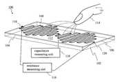
- FIG. 1schematically illustrates a sensor in one embodiment of the invention.
- the sensor 100includes an insulating support 102 defining a front side 104 .
- a membrane 106is arranged on the front side 104 of the insulting support 102 .
- the membrane 106includes at least one layer including a pattern 108 of indium tin oxide (ITO).
- ITOindium tin oxide
- the sensor 100further comprises a capacitance measuring unit 110 configured for measuring a capacitance between the pattern 108 and its surrounding environment.
- the capacitance measuring unit 110is connected to the ITO pattern 108 through a contact point 112 .
- the surrounding environmentmay include a finger 114 , hand or other object, which may modify the capacitance measured by the capacitance measuring unit 110 , when active.
- CapTouch Programmable Controllerfor Single Electrode Capacitance Sensors AD7147 manufactured by Analog Devices, Norwood, Mass., U.S.A.
- CapTouchTM Programmable Controllerfor Single Electrode Capacitance Sensors , AD7147, Preliminary Technical Data, 06/07—Preliminary version F, 2007 published Analog Devices, Inc
- page 11 of the data sheetprovides explanations of a possible mode of operation of the capacitance measuring unit 110 .
- the capacitance measuring unit 110is not limited to the above-described exemplary AD7147 capacitance measuring unit. Other capacitance measuring units 110 may be used.
- the sensor 110also includes a resistance measuring unit 116 configured for measuring the resistance between a pair of points 118 , 120 of the ITO pattern 108 .
- ITOhas good piezoresistive properties as explained in S. E. Dyer, O. J. Gregory, P. S. Amons and A. Bruins Slot, Preparation and piezoresistive properties of reactively sputtered indium tin oxide thin films , Presented at the 22nd International Conference on Metallurgical Coatings and Thin Films (ICMCTF 1995 ), San Diego, Calif., Apr. 24-28, 1995: “Room-temperature gage factors R/R o as large as ⁇ 77.71 were measured on patterned ITO films. These gage factors are considerably larger than those reported for refractory metal alloys.
- the capacitance measuring unit 110is configured to detect the presence of a finger 114 , hand or other object at the surface of or in the vicinity or proximity of the surface of the sensor 100 .
- a cover sheet of plastic or glass(not illustrated) may be arranged at the surface of the sensor 110 on top of the membrane 106 .
- the cover sheet of plastic or glassmay act as a protecting element.
- the resistance measuring unit 116is configured to detect whether a force is exerted by the finger 114 , hand or other object, when the finger 114 , hand or other object is placed at the surface of the sensor 100 .
- the resistance measuring unit 116may also be configured to estimate the force exerted by the finger 114 , hand or other object, when the finger 114 , hand or other object is placed at the surface of the sensor 100 .
- the membrane 106which is in one embodiment resilient, is bent due to the force exerted by the finger 114 , hand or other object on the surface of the sensor 100 , and the length of the ITO pattern 108 between the contact points 118 and 120 is modified. Thanks to the piezoresistive properties of the ITO conductive pattern, the resistance is modified and can be measured by the resistance measuring unit 116 , so that an exerted force can be detected and the exerted force can further be estimated.
- a signal output (not illustrated) of the resistance measuring unit 116 representing the resistancemay be converted to a signal representing a force.
- different actionsmay be triggered in the control logic of the user interface. For instance, if the measured force exceeds a predetermined threshold, a first action is carried out. If the measured force does not exceed the predetermined threshold, a second action is carried out.
- the force measurementis one channel measurement. Namely, one force measurement is obtained for the whole panel by the resistance measuring unit 116 , while the finger position is provided by the capacitance measuring unit 110 . In one embodiment, several force measurements are made in different portions of the membrane.
- the resistance measuring unit 116configured to measure the electrical resistance between a pair of points 118 , 120 of the ITO pattern 108 may for instance be implemented using a Wheatstone bridge. An exemplary circuit diagram of such a circuit is shown in FIG. 5 . Referring to FIG. 5 , the ITO pattern 108 , the electrical resistance to be measured, may be connected as R 1 .
- the amplifiermay be any type of suitable operational amplifier.
- the resistance measuring unit 116is not however limited to this exemplary implementation based on a Wheatstone bridge. Other resistance measuring units 116 may be used.
- the glass or plastic window in front of a displaymay be covered with layers of ITO and then acts as a membrane 106 .
- the force from the user's finger, hand or other objectcauses a strain in this membrane 106 which can be measured by the piezoresistive resistor structure. This makes it possible to measure the force from the user's finger 114 , hand or other object.
- the sensitivitymay vary depending on where the force is applied. This is however predictable and can be compensated using a look-up table where the X and Y coordinates are used as input parameters.
- a controlling unit(not illustrated) may be further provided for controlling the activation of the capacitance measuring unit 110 and the resistance measuring unit 116 .
- the controlling unitis configured to activate, i.e. to switch on, the resistance measuring unit 116 only when the capacitance measuring unit 110 outputs a signal indicating the detection of a finger 114 , hand or other object on the surface of the sensor 100 .
- this configurationsaves power by not permanently activating the resistance measuring unit 116 .
- the resistance measurement unit 116does not need to start until an interrupt from the capacitance measurement unit 116 indicates the presence of a finger, hand or other object on the sensor 100 .
- the capacitance measuring unit 110may output a signal indicating the detection of a finger 114 , hand or other object on the surface of the sensor 100 when the change in measured capacitance exceeds a predetermined threshold.
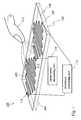
- FIG. 2schematically illustrates a sensor 100 in another embodiment of the invention.
- a membrane 106On the front side 104 of the insulating support 102 , a membrane 106 includes a pattern 108 a , 108 b of ITO.
- the pattern 108 a , 108 bincludes a first portion 108 a and a second portion 108 b .
- a first capacitance measuring unit 110 ais electrically connected to the ITO portion 108 a to measure the capacitance between the portion 108 a and its surrounding environment, which may at one point in time include a finger 114 , hand (not illustrated) or other object (not illustrated).
- a first resistance measuring unit 116 ais connected through contact points 118 a , 120 a to measure the resistance between the pair of contact points 118 a , 120 a of the pattern portion 108 a .
- a finger 114 , hand or other objectcan be detected in the proximity of the portion 108 a by the first capacitance measuring unit 110 a , and the force exerted by the finger 114 , hand or other object on the membrane 106 can be estimated by the first resistance measuring unit 116 a.
- a second capacitance measuring unit 110 bis electrically connected to a second ITO pattern 108 b in order to detect the presence of a finger 114 in the vicinity of the portion 108 b . Furthermore, a second resistance measuring unit 116 b is connected between two contact points 118 b , 120 b in order to measure the resistance between the pair of contact points 118 b , 120 b of the second portion 108 b .
- a plurality of presence detections and a plurality of force detections or measurementscan be made at a plurality of distinct portions of the membrane 106 .
- one force measurementmay be obtained only by one resistance measuring unit 106 , while the finger 114 position is provided by a plurality of capacitance measuring units 110 .
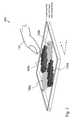
- FIG. 3schematically illustrates a sensor 100 in another embodiment of the invention.
- the membrane 106is made of two layers. Each layer includes an ITO pattern 108 .
- the first layerincludes a first ITO pattern portion 108 a and a second ITO pattern portion 108 b .
- the second layerincludes a third ITO pattern portion 108 c and a fourth ITO pattern portion 108 d .
- Capacitance measuring units(not illustrated in FIG. 3 ) are provided to measure the capacitance between each ITO pattern portion 108 a , 108 b , 108 c , 108 d and their respective surrounding environment. Resistance measuring units (not illustrated in FIG.
- each ITO pattern portionis provided to measure the resistance between the contact points of each ITO pattern portion in order to detect a force and/or estimate a force exerted by a finger 114 on the membrane 106 in the region of the corresponding ITO pattern portion 108 a , 108 b , 108 c , 108 d.
- the capacitance measuring units electrically connected to each of the ITO pattern portions 108 a , 108 bprovide an indication of the position of the finger 114 on the membrane along the x direction (as indicated in FIG. 3 ).
- the capacitance measuring units electrically connected to each of the ITO pattern portions 108 c , 108 dprovide an indication of the position of the finger 114 on the membrane 116 in the y direction.
- the membrane 106may include more than two layers.
- the ITO pattern portionsmay be in the form of a serpentine (as illustrated in FIG. 3 ) or of any other form.
- the number of ITO pattern portions on each layermay be different.
- FIG. 4is a schematic front view of layers of a membrane 106 of a sensor 100 in one embodiment of the invention.
- the three rows of ITO pattern portions labelled “L 1 ”are each associated with one capacitance measuring unit and one resistance measuring unit.
- Each column of ITO pattern portions labelled by “L 2 ”is associated with one capacitance measuring unit and one resistance measuring unit. From the value of capacitance and resistance measurements for each row and column, the position of a finger on the membrane and the force exerted by the finger thereon may be estimated.
- the senor in one embodimenthas a structure similar to a strain gauge using the piezoresistive effect in the ITO layers, which is combined with the capacitive sensing.
- the physical entities according to the invention and/or its embodiments, including the capacitance measuring units, the resistance measuring units and the controlling unit,may comprise or store computer programs including instructions such that, when the computer programs are executed on the physical entities, steps, procedures and functions of these units are carried out according to embodiments of the invention.
- the inventionalso relates to such computer programs for carrying out the function of the units, and to any computer-readable medium storing the computer programs for carrying out methods according to the invention.
- capacitance measuring unitresistance measuring unit
- controlling unitcontrolling unit
- Any one of the above-referred units of a sensor 100may be implemented in hardware, software, field-programmable gate array (FPGA), application-specific integrated circuit (ASICs), firmware or the like.
- FPGAfield-programmable gate array
- ASICsapplication-specific integrated circuit
- any one of the above-mentioned and/or claimed capacitance measuring units, resistance measuring units and controlling unitsis replaced by capacitance measuring means, resistance measuring means and controlling means respectively, or by a capacitance measurer, resistance measurer and controller respectively, for performing the functions of the capacitance measuring units, resistance measuring units and controlling units.
- any one of the above-described stepsmay be implemented using computer-readable instructions, for instance in the form of computer-understandable procedures, methods or the like, in any kind of computer languages, and/or in the form of embedded software on firmware, integrated circuits or the like.
Landscapes
- Engineering & Computer Science (AREA)
- General Engineering & Computer Science (AREA)
- Theoretical Computer Science (AREA)
- Human Computer Interaction (AREA)
- Physics & Mathematics (AREA)
- General Physics & Mathematics (AREA)
- Position Input By Displaying (AREA)
- Force Measurement Appropriate To Specific Purposes (AREA)
- Measurement Of Length, Angles, Or The Like Using Electric Or Magnetic Means (AREA)
- User Interface Of Digital Computer (AREA)
Abstract
Description
Claims (15)
Priority Applications (7)
| Application Number | Priority Date | Filing Date | Title |
|---|---|---|---|
| US12/368,462US8305358B2 (en) | 2009-02-10 | 2009-02-10 | Sensor, display including a sensor, and method for using a sensor |
| KR1020117018652AKR101597861B1 (en) | 2009-02-10 | 2009-08-10 | Sensor, display including a sensor, and method for using a sensor |
| CN200980156431.4ACN102308269B (en) | 2009-02-10 | 2009-08-10 | Sensor, display including sensor, and method of using sensor |
| EP09781655.7AEP2396715B1 (en) | 2009-02-10 | 2009-08-10 | Sensor, display including a sensor, and method for using a sensor |
| JP2011548549AJP5406944B2 (en) | 2009-02-10 | 2009-08-10 | Sensor, display including sensor, and method of using sensor |
| PCT/EP2009/060325WO2010091744A1 (en) | 2009-02-10 | 2009-08-10 | Sensor, display including a sensor, and method for using a sensor |
| TW098141955ATWI514207B (en) | 2009-02-10 | 2009-12-08 | Sensor, display including a sensor, and method for using a sensor |
Applications Claiming Priority (1)
| Application Number | Priority Date | Filing Date | Title |
|---|---|---|---|
| US12/368,462US8305358B2 (en) | 2009-02-10 | 2009-02-10 | Sensor, display including a sensor, and method for using a sensor |
Publications (2)
| Publication Number | Publication Date |
|---|---|
| US20100201635A1 US20100201635A1 (en) | 2010-08-12 |
| US8305358B2true US8305358B2 (en) | 2012-11-06 |
Family
ID=41226469
Family Applications (1)
| Application Number | Title | Priority Date | Filing Date |
|---|---|---|---|
| US12/368,462Expired - Fee RelatedUS8305358B2 (en) | 2009-02-10 | 2009-02-10 | Sensor, display including a sensor, and method for using a sensor |
Country Status (7)
| Country | Link |
|---|---|
| US (1) | US8305358B2 (en) |
| EP (1) | EP2396715B1 (en) |
| JP (1) | JP5406944B2 (en) |
| KR (1) | KR101597861B1 (en) |
| CN (1) | CN102308269B (en) |
| TW (1) | TWI514207B (en) |
| WO (1) | WO2010091744A1 (en) |
Cited By (50)
| Publication number | Priority date | Publication date | Assignee | Title |
|---|---|---|---|---|
| US20120081328A1 (en)* | 2009-06-24 | 2012-04-05 | Thomas Kandziora | Electrode arrangement for display device |
| US20130076646A1 (en)* | 2011-09-23 | 2013-03-28 | Christoph Horst Krah | Force sensor interface for touch controller |
| US20130154998A1 (en)* | 2011-12-16 | 2013-06-20 | Bingrui Yang | Electronic Device with Noise-Cancelling Force Sensor |
| AU2015100030B4 (en)* | 2014-01-13 | 2015-09-17 | Apple Inc. | Temperature compensating transparent force sensor having a compliant layer |
| AU2015101546B4 (en)* | 2014-01-13 | 2016-06-09 | Apple Inc. | Temperature compensating transparent force sensor having a compliant layer |
| US20160259465A1 (en)* | 2015-03-06 | 2016-09-08 | Apple Inc. | Reducing Noise in a Force Signal in an Electronic Device |
| US9483984B2 (en) | 2013-09-11 | 2016-11-01 | Samsung Display Co., Ltd. | Touch sensing display device |
| US20170010719A1 (en)* | 2015-07-10 | 2017-01-12 | Tpk Touch Solutions (Xiamen) Inc. | Pressure sensing input equipment |
| AU2016101043B4 (en)* | 2014-01-13 | 2017-03-09 | Apple Inc. | Temperature compensating transparent force sensor having a compliant layer |
| US9612170B2 (en) | 2015-07-21 | 2017-04-04 | Apple Inc. | Transparent strain sensors in an electronic device |
| US20170123548A1 (en)* | 2015-10-29 | 2017-05-04 | Texas Instruments Incorporated | Integrated force sensing element |
| US9779676B2 (en) | 2014-09-30 | 2017-10-03 | Apple Inc. | Integrated touch sensor and force sensor for an electronic device |
| US9851845B2 (en) | 2014-08-12 | 2017-12-26 | Apple Inc. | Temperature compensation for transparent force sensors |
| US9857246B2 (en)* | 2014-09-17 | 2018-01-02 | Sensable Technologies, Llc | Sensing system including a sensing membrane |
| US9864895B1 (en)* | 2016-07-07 | 2018-01-09 | Fingerprint Cards Ab | Fingerprint sensing system with finger detect |
| US9874965B2 (en) | 2015-09-11 | 2018-01-23 | Apple Inc. | Transparent strain sensors in an electronic device |
| US9886118B2 (en) | 2015-09-30 | 2018-02-06 | Apple Inc. | Transparent force sensitive structures in an electronic device |
| US9891770B2 (en) | 2015-08-28 | 2018-02-13 | Apple Inc. | Methods for forming a patterned structure in a sensor |
| US9952703B2 (en) | 2013-03-15 | 2018-04-24 | Apple Inc. | Force sensing of inputs through strain analysis |
| US9965092B2 (en)* | 2016-05-18 | 2018-05-08 | Apple Inc. | Managing power consumption of force sensors |
| US9983715B2 (en) | 2012-12-17 | 2018-05-29 | Apple Inc. | Force detection in touch devices using piezoelectric sensors |
| US10006820B2 (en) | 2016-03-08 | 2018-06-26 | Apple Inc. | Magnetic interference avoidance in resistive sensors |
| US10055048B2 (en) | 2015-07-31 | 2018-08-21 | Apple Inc. | Noise adaptive force touch |
| US10088937B2 (en) | 2012-05-03 | 2018-10-02 | Apple Inc. | Touch input device including a moment compensated bending sensor for load measurement on platform supported by bending beams |
| US10101857B2 (en) | 2015-08-28 | 2018-10-16 | Apple Inc. | Methods for integrating a compliant material with a substrate |
| US10120478B2 (en) | 2013-10-28 | 2018-11-06 | Apple Inc. | Piezo based force sensing |
| US10133418B2 (en) | 2016-09-07 | 2018-11-20 | Apple Inc. | Force sensing in an electronic device using a single layer of strain-sensitive structures |
| US10146360B2 (en) | 2016-04-29 | 2018-12-04 | Synaptics Incorporated | Hybrid capacitive and resistive sensing for force and touch |
| US10152187B2 (en) | 2014-09-26 | 2018-12-11 | Apple Inc. | Electronic device with an integrated touch sensing and force sensing device |
| US10185397B2 (en) | 2015-03-08 | 2019-01-22 | Apple Inc. | Gap sensor for haptic feedback assembly |
| US10209830B2 (en) | 2016-03-31 | 2019-02-19 | Apple Inc. | Electronic device having direction-dependent strain elements |
| US10263174B2 (en) | 2013-03-15 | 2019-04-16 | Nano Composite Products, Inc. | Composite material used as a strain gauge |
| US10260968B2 (en) | 2013-03-15 | 2019-04-16 | Nano Composite Products, Inc. | Polymeric foam deformation gauge |
| US10282014B2 (en) | 2013-09-30 | 2019-05-07 | Apple Inc. | Operating multiple functions in a display of an electronic device |
| US10296146B2 (en) | 2015-12-22 | 2019-05-21 | Microsoft Technology Licensing, Llc | System and method for detecting grip of a touch enabled device |
| US10296148B2 (en) | 2016-08-31 | 2019-05-21 | Synaptics Incorporated | Full-bridge strain-gauge array of finger thermal compensation |
| US10309846B2 (en) | 2017-07-24 | 2019-06-04 | Apple Inc. | Magnetic field cancellation for strain sensors |
| US10353506B2 (en) | 2017-06-16 | 2019-07-16 | Apple Inc. | Dual resistive strain and pressure sensor for force touch |
| US10394359B2 (en) | 2013-12-20 | 2019-08-27 | Apple Inc. | Reducing display noise in an electronic device |
| US10405779B2 (en) | 2015-01-07 | 2019-09-10 | Nano Composite Products, Inc. | Shoe-based analysis system |
| US10416811B2 (en) | 2015-09-24 | 2019-09-17 | Apple Inc. | Automatic field calibration of force input sensors |
| US10423268B2 (en) | 2015-12-22 | 2019-09-24 | Microsoft Technology Licensing, Llc | System and method for detecting grounding state of a touch enabled computing device |
| US10444091B2 (en) | 2017-04-11 | 2019-10-15 | Apple Inc. | Row column architecture for strain sensing |
| US20190339817A1 (en)* | 2018-05-02 | 2019-11-07 | Samsung Display Co., Ltd. | Input sensing device and display device including the same |
| US10496215B2 (en) | 2016-04-29 | 2019-12-03 | Synaptics Incorporated | Sensing for touch and force |
| US10616349B2 (en) | 2018-05-01 | 2020-04-07 | Microsoft Technology Licensing, Llc | Hybrid sensor centric recommendation engine |
| US10678348B2 (en) | 2018-03-12 | 2020-06-09 | Microsoft Technology Licensing, Llc | Touch detection on an ungrounded pen enabled device |
| US10782818B2 (en) | 2018-08-29 | 2020-09-22 | Apple Inc. | Load cell array for detection of force input to an electronic device enclosure |
| US10795509B2 (en) | 2016-03-24 | 2020-10-06 | Synaptics Incorporated | Force sensing within display stack |
| US10871847B2 (en) | 2017-09-29 | 2020-12-22 | Apple Inc. | Sensing force and press location in absence of touch information |
Families Citing this family (54)
| Publication number | Priority date | Publication date | Assignee | Title |
|---|---|---|---|---|
| US7920129B2 (en) | 2007-01-03 | 2011-04-05 | Apple Inc. | Double-sided touch-sensitive panel with shield and drive combined layer |
| US20090174676A1 (en) | 2008-01-04 | 2009-07-09 | Apple Inc. | Motion component dominance factors for motion locking of touch sensor data |
| FR2949007B1 (en)* | 2009-08-07 | 2012-06-08 | Nanotec Solution | DEVICE AND METHOD FOR CONTROL INTERFACE SENSITIVE TO A MOVEMENT OF A BODY OR OBJECT AND CONTROL EQUIPMENT INCORPORATING THIS DEVICE. |
| US20110193786A1 (en)* | 2010-02-08 | 2011-08-11 | Sony Ericsson Mobile Communications Ab | Touchscreen displays for an electronic device that include separate carbon nanotube layers for determining location and force, respectively |
| TWI421756B (en)* | 2010-12-23 | 2014-01-01 | Au Optronics Corp | Touch display panel and touch sensing panel |
| FR2976688B1 (en) | 2011-06-16 | 2021-04-23 | Nanotec Solution | DEVICE AND METHOD FOR GENERATING AN ELECTRICAL POWER SUPPLY IN AN ELECTRONIC SYSTEM WITH A VARIABLE REFERENCE POTENTIAL. |
| US8780074B2 (en)* | 2011-07-06 | 2014-07-15 | Sharp Kabushiki Kaisha | Dual-function transducer for a touch panel |
| US20130018489A1 (en)* | 2011-07-14 | 2013-01-17 | Grunthaner Martin Paul | Combined force and proximity sensing |
| US9791950B2 (en)* | 2011-08-31 | 2017-10-17 | Sony Corporation | Liquid crystal display |
| EP2748695B1 (en)* | 2011-09-16 | 2019-01-02 | Sony Mobile Communications Inc. | Force sensitive touch sensor |
| FR2985049B1 (en) | 2011-12-22 | 2014-01-31 | Nanotec Solution | CAPACITIVE MEASURING DEVICE WITH SWITCHED ELECTRODES FOR TOUCHLESS CONTACTLESS INTERFACES |
| US8600450B2 (en) | 2011-12-28 | 2013-12-03 | Sony Corporation | Receiving user input on a graphical user interface |
| EP2825937B1 (en)* | 2012-03-15 | 2017-04-19 | Sony Mobile Communications Inc | Method for controlling a touch sensor |
| US9024909B2 (en)* | 2012-04-02 | 2015-05-05 | Nokia Corporation | Sensing |
| TWI463389B (en) | 2012-06-28 | 2014-12-01 | Chunghwa Picture Tubes Ltd | Capacitive touch system and method of operating a capacitive touch system |
| CN102890590B (en)* | 2012-09-07 | 2015-10-21 | 华映光电股份有限公司 | The method of capacitance touching control system and operation of capacitor touch-control system |
| US9366708B2 (en) | 2013-02-06 | 2016-06-14 | Nokia Technologies Oy | Apparatus comprising a flexible substrate and a component supported by the flexible substrate |
| US9336723B2 (en) | 2013-02-13 | 2016-05-10 | Apple Inc. | In-cell touch for LED |
| GB2519581A (en) | 2013-10-28 | 2015-04-29 | Nokia Corp | An apparatus, method and computer program for sensing |
| CN116560524B (en) | 2013-12-13 | 2024-10-01 | 苹果公司 | Integrated touch and display architecture for self-capacitance touch sensor |
| US10133382B2 (en) | 2014-05-16 | 2018-11-20 | Apple Inc. | Structure for integrated touch screen |
| WO2015178920A1 (en) | 2014-05-22 | 2015-11-26 | Onamp Research Llc | Panel bootstrapping architectures for in-cell self-capacitance |
| WO2016072983A1 (en) | 2014-11-05 | 2016-05-12 | Onamp Research Llc | Common electrode driving and compensation for pixelated self-capacitance touch screen |
| GB2533667B (en) | 2014-12-23 | 2017-07-19 | Cambridge Touch Tech Ltd | Pressure-sensitive touch panel |
| EP3457263A1 (en) | 2014-12-23 | 2019-03-20 | Cambridge Touch Technologies, Ltd. | Pressure-sensitive touch panel |
| US10795488B2 (en) | 2015-02-02 | 2020-10-06 | Apple Inc. | Flexible self-capacitance and mutual capacitance touch sensing system architecture |
| US10146359B2 (en) | 2015-04-28 | 2018-12-04 | Apple Inc. | Common electrode auto-compensation method |
| CN106293285A (en)* | 2015-06-09 | 2017-01-04 | 南昌欧菲光科技有限公司 | Touch screen and display device |
| US10386962B1 (en) | 2015-08-03 | 2019-08-20 | Apple Inc. | Reducing touch node electrode coupling |
| GB2544353B (en) | 2015-12-23 | 2018-02-21 | Cambridge Touch Tech Ltd | Pressure-sensitive touch panel |
| US10282046B2 (en) | 2015-12-23 | 2019-05-07 | Cambridge Touch Technologies Ltd. | Pressure-sensitive touch panel |
| JP6681765B2 (en)* | 2016-03-29 | 2020-04-15 | 株式会社ジャパンディスプレイ | Detector |
| KR102469364B1 (en)* | 2016-04-01 | 2022-11-23 | 주식회사 아모센스 | Touch Pressure Sensor |
| CN106020559B (en)* | 2016-06-30 | 2018-05-29 | 华为技术有限公司 | Pressure sensitive detection device, electronic equipment and touch display screen |
| CN105975137B (en)* | 2016-07-07 | 2020-11-03 | 上海天马微电子有限公司 | Touch display panel and touch display device |
| EP3491500B1 (en) | 2016-07-29 | 2023-11-29 | Apple Inc. | Touch sensor panel with multi-power domain chip configuration |
| US10152182B2 (en) | 2016-08-11 | 2018-12-11 | Microsoft Technology Licensing, Llc | Touch sensor having jumpers |
| WO2018043588A1 (en) | 2016-08-30 | 2018-03-08 | シャープ株式会社 | Capacitance type touch panel with built-in pressure sensor |
| DE102016220361A1 (en) | 2016-10-18 | 2018-04-19 | Audi Ag | Operating device for a motor vehicle and motor vehicle |
| US10095342B2 (en)* | 2016-11-14 | 2018-10-09 | Google Llc | Apparatus for sensing user input |
| US10001808B1 (en) | 2017-03-29 | 2018-06-19 | Google Llc | Mobile device accessory equipped to communicate with mobile device |
| US10013081B1 (en) | 2017-04-04 | 2018-07-03 | Google Llc | Electronic circuit and method to account for strain gauge variation |
| US10514797B2 (en) | 2017-04-18 | 2019-12-24 | Google Llc | Force-sensitive user input interface for an electronic device |
| US10635255B2 (en) | 2017-04-18 | 2020-04-28 | Google Llc | Electronic device response to force-sensitive interface |
| US10642418B2 (en) | 2017-04-20 | 2020-05-05 | Apple Inc. | Finger tracking in wet environment |
| GB2565305A (en) | 2017-08-08 | 2019-02-13 | Cambridge Touch Tech Ltd | Device for processing signals from a pressure-sensing touch panel |
| US11093088B2 (en) | 2017-08-08 | 2021-08-17 | Cambridge Touch Technologies Ltd. | Device for processing signals from a pressure-sensing touch panel |
| CN107393497A (en)* | 2017-08-30 | 2017-11-24 | 上海天马微电子有限公司 | Display panel and display device |
| CN109959358B (en)* | 2017-12-22 | 2020-10-23 | 深圳光启超材料技术有限公司 | Measuring film, method for manufacturing measuring film, and method for measuring plane strain field |
| US11638353B2 (en)* | 2018-09-17 | 2023-04-25 | Hutchinson Technology Incorporated | Apparatus and method for forming sensors with integrated electrical circuits on a substrate |
| US11662867B1 (en) | 2020-05-30 | 2023-05-30 | Apple Inc. | Hover detection on a touch sensor panel |
| CN114023257B (en)* | 2021-11-12 | 2023-07-25 | 云谷(固安)科技有限公司 | Display panel, display panel driving method and display device |
| WO2023113763A2 (en)* | 2021-12-19 | 2023-06-22 | Hacettepe Universitesi Rektorluk | Flexible force measuring tactile sensor system |
| CN114543644B (en)* | 2022-02-18 | 2022-11-15 | 广州市欧智智能科技有限公司 | A head position detection method, device, terminal and medium |
Citations (27)
| Publication number | Priority date | Publication date | Assignee | Title |
|---|---|---|---|---|
| US4435616A (en)* | 1981-08-25 | 1984-03-06 | Kley Victor B | Graphical data entry apparatus |
| EP0348229A2 (en) | 1988-06-24 | 1989-12-27 | E.I. Du Pont De Nemours And Company | Touch screen overlay with improved conductor durability |
| US5369228A (en)* | 1991-11-30 | 1994-11-29 | Signagraphics Corporation | Data input device with a pressure-sensitive input surface |
| GB2288665A (en) | 1994-04-21 | 1995-10-25 | Samsung Display Devices Co Ltd | Information input apparatus having functions of both touch panel and digitizer, and driving method therof |
| US5777607A (en)* | 1995-02-22 | 1998-07-07 | U.S. Philips Corporation | Low-cost resistive tablet with touch and stylus functionality |
| US5915285A (en) | 1993-01-21 | 1999-06-22 | Optical Coating Laboratory, Inc. | Transparent strain sensitive devices and method |
| US6208332B1 (en)* | 1997-09-17 | 2001-03-27 | Nec Corporation | Resistance film tablet system capable of rapidly detecting a position of contact and method of controlling the same |
| WO2005073834A2 (en) | 2004-01-30 | 2005-08-11 | Ford Global Technologies, Llc | Touch screens |
| US20070062739A1 (en)* | 2005-09-20 | 2007-03-22 | Harald Philipp | Touch Sensitive Screen |
| US20070139391A1 (en)* | 2005-11-18 | 2007-06-21 | Siemens Aktiengesellschaft | Input device |
| US20080018608A1 (en)* | 2006-07-18 | 2008-01-24 | Bogdan Serban | Data input device |
| US20080204418A1 (en)* | 2007-02-27 | 2008-08-28 | Adam Cybart | Adaptable User Interface and Mechanism for a Portable Electronic Device |
| US20080231605A1 (en)* | 2007-03-21 | 2008-09-25 | Kai-Ti Yang | Compound touch panel |
| US20080303797A1 (en)* | 2007-06-11 | 2008-12-11 | Honeywell International, Inc. | Stimuli sensitive display screen with multiple detect modes |
| US20080316182A1 (en)* | 2007-06-21 | 2008-12-25 | Mika Antila | Touch Sensor and Method for Operating a Touch Sensor |
| US20090020343A1 (en)* | 2007-07-17 | 2009-01-22 | Apple Inc. | Resistive force sensor with capacitive discrimination |
| US20090096763A1 (en)* | 2007-10-16 | 2009-04-16 | Epson Imaging Devices Corporation | Touch panel, display device with input function, and electronic apparatus |
| US20090140987A1 (en)* | 2007-12-04 | 2009-06-04 | Kai-Ti Yang | Duplex touch panel |
| US20090152023A1 (en)* | 2007-12-12 | 2009-06-18 | J Touch Corporation | Hybrid touch panel and method making thereof |
| US20090189875A1 (en)* | 2008-01-29 | 2009-07-30 | Research In Motion Limited | Electronic device and touch screen display |
| US20090225051A1 (en)* | 2008-03-04 | 2009-09-10 | Wintek Corporation | Touch panel |
| US20090309616A1 (en)* | 2008-06-13 | 2009-12-17 | Sony Ericsson Mobile Communications Ab | Touch and force sensing for input devices |
| US20090315845A1 (en)* | 2006-09-26 | 2009-12-24 | Koninklijke Philips Electronics N.V. | Touch sensor |
| US20100078231A1 (en)* | 2008-09-30 | 2010-04-01 | J Touch Corporation | Dual-side integrated touch panel structure |
| US20100123686A1 (en)* | 2008-11-19 | 2010-05-20 | Sony Ericsson Mobile Communications Ab | Piezoresistive force sensor integrated in a display |
| US20100141591A1 (en)* | 2008-12-09 | 2010-06-10 | Lin Chien-Huang | Composite touch panel and method for operating the same |
| US8089470B1 (en)* | 1998-10-20 | 2012-01-03 | Synaptics Incorporated | Finger/stylus touch pad |
Family Cites Families (11)
| Publication number | Priority date | Publication date | Assignee | Title |
|---|---|---|---|---|
| JPS6212825A (en)* | 1985-07-10 | 1987-01-21 | Shinei Kk | Power sensitive sensor and its measuring instrument |
| JPS63108423A (en)* | 1986-10-27 | 1988-05-13 | Toray Ind Inc | Finger touch type coordinate output device |
| JPH1120607A (en)* | 1997-06-30 | 1999-01-26 | Nabco Ltd | Development controller of air bag for occupant crash protection device |
| US20030067447A1 (en)* | 2001-07-09 | 2003-04-10 | Geaghan Bernard O. | Touch screen with selective touch sources |
| JP2006504948A (en)* | 2002-10-31 | 2006-02-09 | フィリップ、ハラルド | Capacitive position sensor using charge transfer |
| JP2006049271A (en)* | 2004-07-01 | 2006-02-16 | Matsushita Electric Ind Co Ltd | Light transmissive touch panel and detection device using the same |
| TW200606691A (en)* | 2004-08-06 | 2006-02-16 | Disk King Technology Co Ltd | Electronic writing device |
| US20060227114A1 (en)* | 2005-03-30 | 2006-10-12 | Geaghan Bernard O | Touch location determination with error correction for sensor movement |
| JP4920396B2 (en)* | 2006-12-15 | 2012-04-18 | 三菱電機株式会社 | Touch panel control device |
| JP2008197934A (en)* | 2007-02-14 | 2008-08-28 | Calsonic Kansei Corp | Operator determining method |
| JP2008225980A (en)* | 2007-03-14 | 2008-09-25 | Young Fast Optoelectronics Co Ltd | Composite touch sensor |
- 2009
- 2009-02-10USUS12/368,462patent/US8305358B2/ennot_activeExpired - Fee Related
- 2009-08-10CNCN200980156431.4Apatent/CN102308269B/ennot_activeExpired - Fee Related
- 2009-08-10EPEP09781655.7Apatent/EP2396715B1/ennot_activeNot-in-force
- 2009-08-10JPJP2011548549Apatent/JP5406944B2/ennot_activeExpired - Fee Related
- 2009-08-10KRKR1020117018652Apatent/KR101597861B1/ennot_activeExpired - Fee Related
- 2009-08-10WOPCT/EP2009/060325patent/WO2010091744A1/enactiveApplication Filing
- 2009-12-08TWTW098141955Apatent/TWI514207B/ennot_activeIP Right Cessation
Patent Citations (27)
| Publication number | Priority date | Publication date | Assignee | Title |
|---|---|---|---|---|
| US4435616A (en)* | 1981-08-25 | 1984-03-06 | Kley Victor B | Graphical data entry apparatus |
| EP0348229A2 (en) | 1988-06-24 | 1989-12-27 | E.I. Du Pont De Nemours And Company | Touch screen overlay with improved conductor durability |
| US5369228A (en)* | 1991-11-30 | 1994-11-29 | Signagraphics Corporation | Data input device with a pressure-sensitive input surface |
| US5915285A (en) | 1993-01-21 | 1999-06-22 | Optical Coating Laboratory, Inc. | Transparent strain sensitive devices and method |
| GB2288665A (en) | 1994-04-21 | 1995-10-25 | Samsung Display Devices Co Ltd | Information input apparatus having functions of both touch panel and digitizer, and driving method therof |
| US5777607A (en)* | 1995-02-22 | 1998-07-07 | U.S. Philips Corporation | Low-cost resistive tablet with touch and stylus functionality |
| US6208332B1 (en)* | 1997-09-17 | 2001-03-27 | Nec Corporation | Resistance film tablet system capable of rapidly detecting a position of contact and method of controlling the same |
| US8089470B1 (en)* | 1998-10-20 | 2012-01-03 | Synaptics Incorporated | Finger/stylus touch pad |
| WO2005073834A2 (en) | 2004-01-30 | 2005-08-11 | Ford Global Technologies, Llc | Touch screens |
| US20070062739A1 (en)* | 2005-09-20 | 2007-03-22 | Harald Philipp | Touch Sensitive Screen |
| US20070139391A1 (en)* | 2005-11-18 | 2007-06-21 | Siemens Aktiengesellschaft | Input device |
| US20080018608A1 (en)* | 2006-07-18 | 2008-01-24 | Bogdan Serban | Data input device |
| US20090315845A1 (en)* | 2006-09-26 | 2009-12-24 | Koninklijke Philips Electronics N.V. | Touch sensor |
| US20080204418A1 (en)* | 2007-02-27 | 2008-08-28 | Adam Cybart | Adaptable User Interface and Mechanism for a Portable Electronic Device |
| US20080231605A1 (en)* | 2007-03-21 | 2008-09-25 | Kai-Ti Yang | Compound touch panel |
| US20080303797A1 (en)* | 2007-06-11 | 2008-12-11 | Honeywell International, Inc. | Stimuli sensitive display screen with multiple detect modes |
| US20080316182A1 (en)* | 2007-06-21 | 2008-12-25 | Mika Antila | Touch Sensor and Method for Operating a Touch Sensor |
| US20090020343A1 (en)* | 2007-07-17 | 2009-01-22 | Apple Inc. | Resistive force sensor with capacitive discrimination |
| US20090096763A1 (en)* | 2007-10-16 | 2009-04-16 | Epson Imaging Devices Corporation | Touch panel, display device with input function, and electronic apparatus |
| US20090140987A1 (en)* | 2007-12-04 | 2009-06-04 | Kai-Ti Yang | Duplex touch panel |
| US20090152023A1 (en)* | 2007-12-12 | 2009-06-18 | J Touch Corporation | Hybrid touch panel and method making thereof |
| US20090189875A1 (en)* | 2008-01-29 | 2009-07-30 | Research In Motion Limited | Electronic device and touch screen display |
| US20090225051A1 (en)* | 2008-03-04 | 2009-09-10 | Wintek Corporation | Touch panel |
| US20090309616A1 (en)* | 2008-06-13 | 2009-12-17 | Sony Ericsson Mobile Communications Ab | Touch and force sensing for input devices |
| US20100078231A1 (en)* | 2008-09-30 | 2010-04-01 | J Touch Corporation | Dual-side integrated touch panel structure |
| US20100123686A1 (en)* | 2008-11-19 | 2010-05-20 | Sony Ericsson Mobile Communications Ab | Piezoresistive force sensor integrated in a display |
| US20100141591A1 (en)* | 2008-12-09 | 2010-06-10 | Lin Chien-Huang | Composite touch panel and method for operating the same |
Non-Patent Citations (6)
| Title |
|---|
| Analog Devices, CapTouch Programmable Controller for Single Electrode Capacitance Sensors AD7147, Analog Devices, Inc., Norwood, Massachusetts, U.S.A., Preliminary Technical Data, Jun. 2007-Preliminary version F, 2007, pp. 1-68. |
| Analog Devices, CapTouch Programmable Controller for Single Electrode Capacitance Sensors AD7147, Analog Devices, Inc., Norwood, Massachusetts, U.S.A., Preliminary Technical Data, Jun. 2007—Preliminary version F, 2007, pp. 1-68. |
| http://en.wikipedia.org/wiki/Wheatstone bridge (web page). |
| International Search Report, corresponding to PCT/EP2009/060325 mailed Nov. 13, 2009. |
| S.E. Dyer, O.J. Gregory, P.S. Amons and A. Bruins Slot, Preparation and piezoresistive properties of reactively sputttered indium tin oxide thin films, Presented at the 22nd International Conference on Metallurgical Coatings and Thin Films (ICMCTF 1995), San Diego, CA, Apr. 24-28, 1995, pp. 279-286. |
| Written Opinion, corresponding to PCT/EP2009/060325, mailed Nov. 13, 2009. |
Cited By (79)
| Publication number | Priority date | Publication date | Assignee | Title |
|---|---|---|---|---|
| US8487905B2 (en)* | 2009-06-24 | 2013-07-16 | Ident Technology Ag | Electrode arrangement for display device |
| US20120081328A1 (en)* | 2009-06-24 | 2012-04-05 | Thomas Kandziora | Electrode arrangement for display device |
| US20130076646A1 (en)* | 2011-09-23 | 2013-03-28 | Christoph Horst Krah | Force sensor interface for touch controller |
| US8988384B2 (en)* | 2011-09-23 | 2015-03-24 | Apple Inc. | Force sensor interface for touch controller |
| US9575588B2 (en) | 2011-12-16 | 2017-02-21 | Apple Inc. | Electronic device with noise-cancelling force sensor |
| US20130154998A1 (en)* | 2011-12-16 | 2013-06-20 | Bingrui Yang | Electronic Device with Noise-Cancelling Force Sensor |
| US9246486B2 (en)* | 2011-12-16 | 2016-01-26 | Apple Inc. | Electronic device with noise-cancelling force sensor |
| US9791958B2 (en) | 2011-12-16 | 2017-10-17 | Apple Inc. | Electronic device with noise-cancelling force sensor |
| US9983716B2 (en) | 2011-12-16 | 2018-05-29 | Apple Inc. | Electronic device with noise-cancelling force sensor |
| US10088937B2 (en) | 2012-05-03 | 2018-10-02 | Apple Inc. | Touch input device including a moment compensated bending sensor for load measurement on platform supported by bending beams |
| US9983715B2 (en) | 2012-12-17 | 2018-05-29 | Apple Inc. | Force detection in touch devices using piezoelectric sensors |
| US10496212B2 (en) | 2013-03-15 | 2019-12-03 | Apple Inc. | Force sensing of inputs through strain analysis |
| US11329212B2 (en) | 2013-03-15 | 2022-05-10 | Nano Composite Products, Inc. | Composite conductive foam insole |
| US10658567B2 (en) | 2013-03-15 | 2020-05-19 | Nano Composite Products, Inc. | Composite material used as a strain gauge |
| US10263174B2 (en) | 2013-03-15 | 2019-04-16 | Nano Composite Products, Inc. | Composite material used as a strain gauge |
| US9952703B2 (en) | 2013-03-15 | 2018-04-24 | Apple Inc. | Force sensing of inputs through strain analysis |
| US10260968B2 (en) | 2013-03-15 | 2019-04-16 | Nano Composite Products, Inc. | Polymeric foam deformation gauge |
| US11874184B2 (en) | 2013-03-15 | 2024-01-16 | Nano Composite Products, Inc. | Composite conductive foam |
| US10275068B2 (en) | 2013-03-15 | 2019-04-30 | Apple Inc. | Force sensing of inputs through strain analysis |
| US9483984B2 (en) | 2013-09-11 | 2016-11-01 | Samsung Display Co., Ltd. | Touch sensing display device |
| US10282014B2 (en) | 2013-09-30 | 2019-05-07 | Apple Inc. | Operating multiple functions in a display of an electronic device |
| US10120478B2 (en) | 2013-10-28 | 2018-11-06 | Apple Inc. | Piezo based force sensing |
| US10394359B2 (en) | 2013-12-20 | 2019-08-27 | Apple Inc. | Reducing display noise in an electronic device |
| AU2015101546B4 (en)* | 2014-01-13 | 2016-06-09 | Apple Inc. | Temperature compensating transparent force sensor having a compliant layer |
| US10423265B2 (en) | 2014-01-13 | 2019-09-24 | Apple Inc. | Temperature compensating force sensor |
| US10466829B2 (en) | 2014-01-13 | 2019-11-05 | Apple Inc. | Temperature compensating sensor having a compliant layer separating independent force sensing substrates and sense circuitry to obtain a relative measure between the force sensing substrates |
| US9690413B2 (en) | 2014-01-13 | 2017-06-27 | Apple Inc. | Temperature compensating transparent force sensor having a compliant layer |
| US9665200B2 (en) | 2014-01-13 | 2017-05-30 | Apple Inc. | Temperature compensating transparent force sensor |
| AU2016101043B4 (en)* | 2014-01-13 | 2017-03-09 | Apple Inc. | Temperature compensating transparent force sensor having a compliant layer |
| US9542028B2 (en) | 2014-01-13 | 2017-01-10 | Apple Inc. | Temperature compensating transparent force sensor having a compliant layer |
| AU2015100030B4 (en)* | 2014-01-13 | 2015-09-17 | Apple Inc. | Temperature compensating transparent force sensor having a compliant layer |
| US9851845B2 (en) | 2014-08-12 | 2017-12-26 | Apple Inc. | Temperature compensation for transparent force sensors |
| US9857246B2 (en)* | 2014-09-17 | 2018-01-02 | Sensable Technologies, Llc | Sensing system including a sensing membrane |
| US10152187B2 (en) | 2014-09-26 | 2018-12-11 | Apple Inc. | Electronic device with an integrated touch sensing and force sensing device |
| US9779676B2 (en) | 2014-09-30 | 2017-10-03 | Apple Inc. | Integrated touch sensor and force sensor for an electronic device |
| US10043469B2 (en) | 2014-09-30 | 2018-08-07 | Apple Inc. | Integrated touch sensor and force sensor for an electronic device |
| US12220223B2 (en) | 2015-01-07 | 2025-02-11 | Nano Composite Products, Inc. | Shoe-based analysis system |
| US11564594B2 (en) | 2015-01-07 | 2023-01-31 | Nano Composite Products, Inc. | Shoe-based analysis system |
| US10405779B2 (en) | 2015-01-07 | 2019-09-10 | Nano Composite Products, Inc. | Shoe-based analysis system |
| US20160259465A1 (en)* | 2015-03-06 | 2016-09-08 | Apple Inc. | Reducing Noise in a Force Signal in an Electronic Device |
| US10296123B2 (en)* | 2015-03-06 | 2019-05-21 | Apple Inc. | Reducing noise in a force signal in an electronic device |
| US10185397B2 (en) | 2015-03-08 | 2019-01-22 | Apple Inc. | Gap sensor for haptic feedback assembly |
| US20170010719A1 (en)* | 2015-07-10 | 2017-01-12 | Tpk Touch Solutions (Xiamen) Inc. | Pressure sensing input equipment |
| US10698538B2 (en)* | 2015-07-10 | 2020-06-30 | Tpk Touch Solutions (Xiamen) Inc. | Pressure sensing input equipment comprising electrode layer comprising plurality of pressure sensing electrodes and plurality of axial touch sensing electrodes |
| US9612170B2 (en) | 2015-07-21 | 2017-04-04 | Apple Inc. | Transparent strain sensors in an electronic device |
| US10139294B2 (en) | 2015-07-21 | 2018-11-27 | Apple Inc. | Strain sensors in an electronic device |
| US10055048B2 (en) | 2015-07-31 | 2018-08-21 | Apple Inc. | Noise adaptive force touch |
| US9891770B2 (en) | 2015-08-28 | 2018-02-13 | Apple Inc. | Methods for forming a patterned structure in a sensor |
| US10101857B2 (en) | 2015-08-28 | 2018-10-16 | Apple Inc. | Methods for integrating a compliant material with a substrate |
| US9874965B2 (en) | 2015-09-11 | 2018-01-23 | Apple Inc. | Transparent strain sensors in an electronic device |
| US10416811B2 (en) | 2015-09-24 | 2019-09-17 | Apple Inc. | Automatic field calibration of force input sensors |
| US9886118B2 (en) | 2015-09-30 | 2018-02-06 | Apple Inc. | Transparent force sensitive structures in an electronic device |
| US11487381B2 (en) | 2015-10-29 | 2022-11-01 | Texas Instruments Incorporated | Piezoelectric sensor apparatus |
| US10353503B2 (en)* | 2015-10-29 | 2019-07-16 | Texas Instruments Incorporated | Integrated force sensing element |
| US20170123548A1 (en)* | 2015-10-29 | 2017-05-04 | Texas Instruments Incorporated | Integrated force sensing element |
| US10296146B2 (en) | 2015-12-22 | 2019-05-21 | Microsoft Technology Licensing, Llc | System and method for detecting grip of a touch enabled device |
| US10423268B2 (en) | 2015-12-22 | 2019-09-24 | Microsoft Technology Licensing, Llc | System and method for detecting grounding state of a touch enabled computing device |
| US10006820B2 (en) | 2016-03-08 | 2018-06-26 | Apple Inc. | Magnetic interference avoidance in resistive sensors |
| US10795509B2 (en) | 2016-03-24 | 2020-10-06 | Synaptics Incorporated | Force sensing within display stack |
| US11520423B2 (en) | 2016-03-24 | 2022-12-06 | Synaptics Incorporated | Force sensing within display stack |
| US10209830B2 (en) | 2016-03-31 | 2019-02-19 | Apple Inc. | Electronic device having direction-dependent strain elements |
| US10496215B2 (en) | 2016-04-29 | 2019-12-03 | Synaptics Incorporated | Sensing for touch and force |
| US10146360B2 (en) | 2016-04-29 | 2018-12-04 | Synaptics Incorporated | Hybrid capacitive and resistive sensing for force and touch |
| US9965092B2 (en)* | 2016-05-18 | 2018-05-08 | Apple Inc. | Managing power consumption of force sensors |
| US9864895B1 (en)* | 2016-07-07 | 2018-01-09 | Fingerprint Cards Ab | Fingerprint sensing system with finger detect |
| US10296148B2 (en) | 2016-08-31 | 2019-05-21 | Synaptics Incorporated | Full-bridge strain-gauge array of finger thermal compensation |
| US10133418B2 (en) | 2016-09-07 | 2018-11-20 | Apple Inc. | Force sensing in an electronic device using a single layer of strain-sensitive structures |
| US10444091B2 (en) | 2017-04-11 | 2019-10-15 | Apple Inc. | Row column architecture for strain sensing |
| US10353506B2 (en) | 2017-06-16 | 2019-07-16 | Apple Inc. | Dual resistive strain and pressure sensor for force touch |
| US10309846B2 (en) | 2017-07-24 | 2019-06-04 | Apple Inc. | Magnetic field cancellation for strain sensors |
| US10871847B2 (en) | 2017-09-29 | 2020-12-22 | Apple Inc. | Sensing force and press location in absence of touch information |
| US10678348B2 (en) | 2018-03-12 | 2020-06-09 | Microsoft Technology Licensing, Llc | Touch detection on an ungrounded pen enabled device |
| US10616349B2 (en) | 2018-05-01 | 2020-04-07 | Microsoft Technology Licensing, Llc | Hybrid sensor centric recommendation engine |
| US11314366B2 (en)* | 2018-05-02 | 2022-04-26 | Samsung Display Co., Ltd. | Input sensing device and display device including the same |
| US10831329B2 (en)* | 2018-05-02 | 2020-11-10 | Samsung Display Co., Ltd. | Input sensing device and display device including the same |
| US11947763B2 (en) | 2018-05-02 | 2024-04-02 | Samsung Display Co., Ltd. | Input sensing device and display device including the same |
| US20190339817A1 (en)* | 2018-05-02 | 2019-11-07 | Samsung Display Co., Ltd. | Input sensing device and display device including the same |
| US11340725B2 (en) | 2018-08-29 | 2022-05-24 | Apple Inc. | Load cell array for detection of force input to an electronic device enclosure |
| US10782818B2 (en) | 2018-08-29 | 2020-09-22 | Apple Inc. | Load cell array for detection of force input to an electronic device enclosure |
Also Published As
| Publication number | Publication date |
|---|---|
| US20100201635A1 (en) | 2010-08-12 |
| KR20110127147A (en) | 2011-11-24 |
| CN102308269A (en) | 2012-01-04 |
| KR101597861B1 (en) | 2016-02-25 |
| WO2010091744A1 (en) | 2010-08-19 |
| JP5406944B2 (en) | 2014-02-05 |
| EP2396715B1 (en) | 2013-10-02 |
| JP2012517584A (en) | 2012-08-02 |
| EP2396715A1 (en) | 2011-12-21 |
| CN102308269B (en) | 2014-08-13 |
| TWI514207B (en) | 2015-12-21 |
| TW201030574A (en) | 2010-08-16 |
Similar Documents
| Publication | Publication Date | Title |
|---|---|---|
| US8305358B2 (en) | Sensor, display including a sensor, and method for using a sensor | |
| CN108885149B (en) | pressure detection device | |
| CN105975137B (en) | Touch display panel and touch display device | |
| EP2634552B1 (en) | Electronic device and method for determining a temperature of an electronic device | |
| KR100997107B1 (en) | Touch input structure for detecting push force and acting position, touch input device and method for detecting push force and acting position using same | |
| CN205302226U (en) | Electronic equipment with force transducer | |
| US8780074B2 (en) | Dual-function transducer for a touch panel | |
| US9864449B2 (en) | Pressure-sensitive touch screen and touch display screen and electronic device | |
| KR100969504B1 (en) | Sensor integrated touch input device | |
| EP2372506A1 (en) | Touch screen panel and display device having the same | |
| TWI530672B (en) | Input device and input device control method | |
| JP2005530996A5 (en) | ||
| CN105115633A (en) | A pressure sensing apparatus | |
| JP6104370B2 (en) | Touch sensor screen with capacitive sensor array and capacitive sensor array | |
| JPH06195176A (en) | Transparent touch panel | |
| KR101168709B1 (en) | Hybrid type touch pad | |
| EP3065298B1 (en) | An apparatus and method for sensing | |
| EP3803551A1 (en) | Displacement sensing | |
| CN104978065B (en) | Transparent force with strain relief |
Legal Events
| Date | Code | Title | Description |
|---|---|---|---|
| AS | Assignment | Owner name:SONY ERICSSON MOBILE COMMUNICATIONS AB, SWEDEN Free format text:ASSIGNMENT OF ASSIGNORS INTEREST;ASSIGNORS:KLINGHULT, GUNNAR;KLEVERMAN, MATS;REEL/FRAME:022233/0070 Effective date:20090121 | |
| ZAAA | Notice of allowance and fees due | Free format text:ORIGINAL CODE: NOA | |
| ZAAB | Notice of allowance mailed | Free format text:ORIGINAL CODE: MN/=. | |
| STCF | Information on status: patent grant | Free format text:PATENTED CASE | |
| FPAY | Fee payment | Year of fee payment:4 | |
| AS | Assignment | Owner name:SONY MOBILE COMMUNICATIONS AB, SWEDEN Free format text:CHANGE OF NAME;ASSIGNOR:SONY ERICSSON MOBILE COMMUNICATIONS AB;REEL/FRAME:048690/0974 Effective date:20120221 | |
| AS | Assignment | Owner name:SONY CORPORATION, JAPAN Free format text:ASSIGNMENT OF ASSIGNORS INTEREST;ASSIGNOR:SONY MOBILE COMMUNICATIONS AB;REEL/FRAME:048825/0737 Effective date:20190405 | |
| MAFP | Maintenance fee payment | Free format text:PAYMENT OF MAINTENANCE FEE, 8TH YEAR, LARGE ENTITY (ORIGINAL EVENT CODE: M1552); ENTITY STATUS OF PATENT OWNER: LARGE ENTITY Year of fee payment:8 | |
| FEPP | Fee payment procedure | Free format text:MAINTENANCE FEE REMINDER MAILED (ORIGINAL EVENT CODE: REM.); ENTITY STATUS OF PATENT OWNER: LARGE ENTITY | |
| LAPS | Lapse for failure to pay maintenance fees | Free format text:PATENT EXPIRED FOR FAILURE TO PAY MAINTENANCE FEES (ORIGINAL EVENT CODE: EXP.); ENTITY STATUS OF PATENT OWNER: LARGE ENTITY | |
| STCH | Information on status: patent discontinuation | Free format text:PATENT EXPIRED DUE TO NONPAYMENT OF MAINTENANCE FEES UNDER 37 CFR 1.362 | |
| FP | Lapsed due to failure to pay maintenance fee | Effective date:20241106 |